

Page 1
INSTRUCTIONS FOR:
DUAL FUSION® PARAFFIN/KEROSENE &
DIESEL HEATER 120,000/150,000Btu/hr
WITH WHEELS
MODEL No: AB1500Q
1.1. ELECTRICAL SAFETY
WARNING! It is the responsibility of the owner and the operator to read, understand and comply with the following:
You must check all electrical products, before use, to ensure that they are safe. You must inspect power cables, plugs, sockets and
any other connectors for wear or damage. You must ensure that the risk of electric shock is minimised by the installation of
appropriate safety devices. A Residual Current Circuit Breaker (RCCB) should be incorporated in the main distribution board. We also
recommend that a Residual Current Device (RCD) is used. It is particularly important to use an RCD with portable products that are
plugged into a supply which is not protected by an RCCB. If in any doubt consult a qualified electrician. You may obtain a Residual
Current Device by contacting your Sealey dealer.
You must also read and understand the following instructions concerning electrical safety.
1.1.1. The Electricity at Work Act 1989 requires that all portable electrical appliances, if used on business premises, are tested by a qualified
electrician, using a Portable Appliance Tester (PAT), at least once a year.
1.1.2. The Health & Safety at Work Act 1974 makes owners of electrical appliances responsible for the safe condition of those appliances
and the safety of the appliance operators. If in any doubt about electrical safety, contact a qualified electrician.
1.1.3. Ensure that the insulation on all cables and on the appliance is safe before connecting it to the power supply. See 1.1.1. and 1.1.2.
and use a Portable Appliance Tester.
1.1.4. Ensure that cables are always protected against short circuit and overload.
1.1.5. Regularly inspect power supply cables and plugs for wear or damage and check all
connections to ensure that none is loose.
1.1.6. Important: Ensure that the voltage marked on the appliance matches the power supply
to be used and that the plug is fitted with the correct fuse - see fuse rating at right.
1.1.7. DO NOT pull or carry the appliance by the power cable.
1.1.8. DO NOT pull the plug from the socket by the cable.
1.1.9. DO NOT use worn or damaged cables, plugs or connectors. Immediately have any faulty
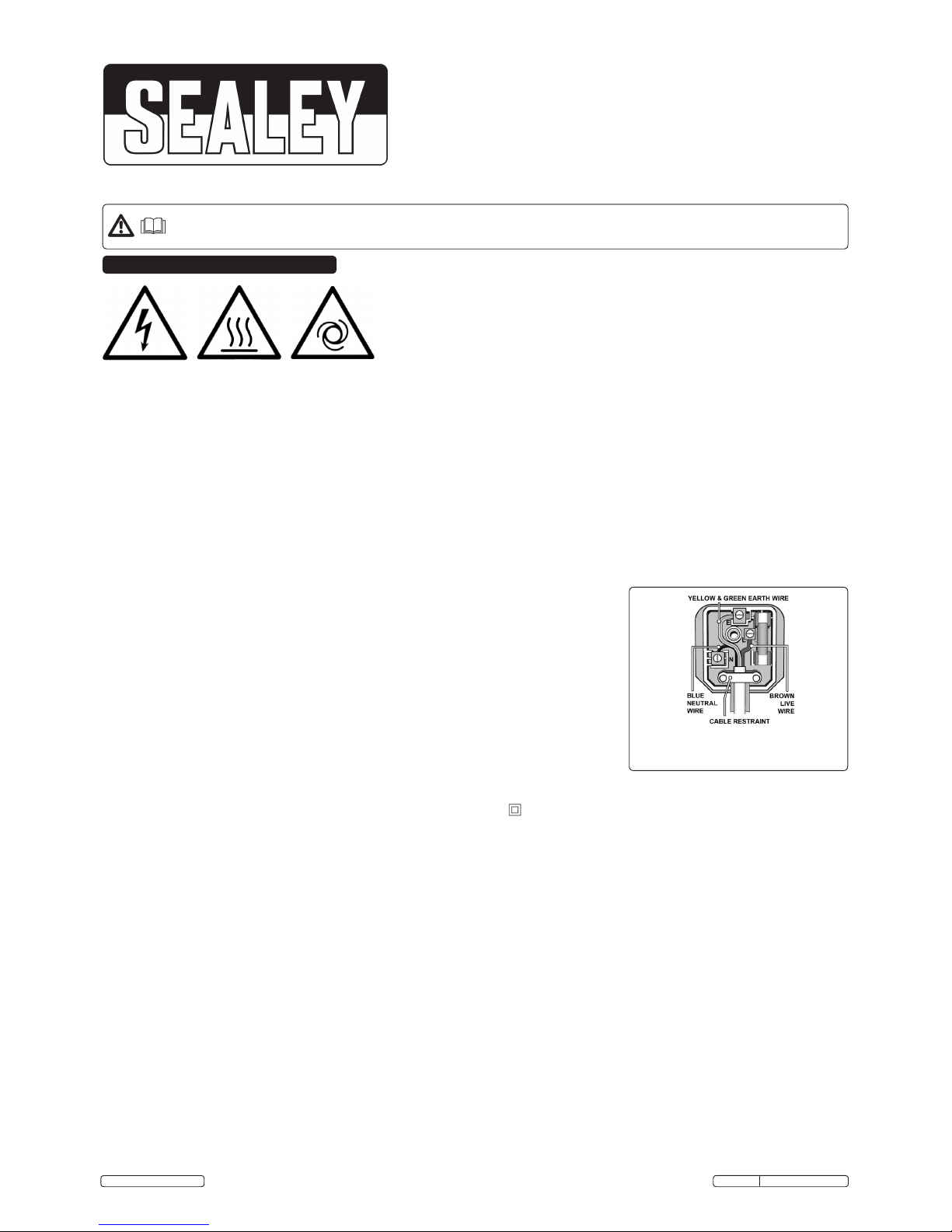
item repaired or replaced by a qualified electrician. When a BS 1363/A UK 3 pin plug is
damaged, cut the cable just above the plug and dispose of the plug safely.
Fit a new plug according to the following instructions (UK only).
a) Connect the GREEN/YELLOW earth wire to the earth terminal ‘E’.
b) Connect the BROWN live wire to the live terminal ‘L’.
c) Connect the BLUE neutral wire to the neutral terminal ‘N’.
d) After wiring, check that there are no bare wires, that all wires have been correctly connected, that the cable outer insulation
extends beyond the cable restraint and that the restraint is tight.
Double insulated products, which are always marked with this symbol , are fitted with live (brown) and neutral (blue) wires only. To
rewire, connect the wires as indicated above.
DO NOT connect either wire to the earth terminal.
1.1.10. Products which require more than 13 amps are supplied without a plug. In this case you must contact a qualified electrician to ensure
that a suitably rated supply is available. We recommend that you discuss the installation of an industrial round pin plug and socket
with your electrician.
1.1.11. If an extension reel is used it should be fully unwound before connection. A reel with an RCD fitted is preferred since any appliance
plugged into it will be protected. The cable core section is important and should be at least 1.5mm², but to be absolutely sure that the
capacity of the reel is suitable for this product and for others which may be used in the other output sockets, we recommend the use
of 2.5mm² section cable.
RECOMMENDED
FUSE RATING: 5AMP
Original Language Version
IMPORTANT: PLEASE READ THESE INSTRUCTIONS CAREFULLY. NOTE THE SAFE OPERATIONAL REQUIREMENTS, WARNINGS & CAUTIONS. USE THE
PRODUCT CORRECTLY AND WITH CARE FOR THE PURPOSE FOR WHICH IT IS INTENDED. FAILURE TO DO SO MAY CAUSE DAMAGE AND/OR
PERSONAL INJURY AND WILL INVALIDATE THE WARRANTY. KEEP THESE INSTRUCTIONS SAFE FOR FUTURE USE.
Thank you for purchasing a Sealey product. Manufactured to a high standard, this product will, if used according to these
instructions, and properly maintained, give you years of trouble free performance.
1. SAFETY
© Jack Sealey Limited
Electrical
Hazard
Hot
Surface
Unexpected
Start Up
1.2. GENERAL SAFETY
DANGER! Risk of carbon monoxide poisoning. Failure to provide proper ventilation could result in serious illness or death.
Check that the heater is in sound condition and good working order. Take immediate action to repair or replace damaged parts.
Use recommended parts only. Unauthorised parts may be dangerous and will invalidate the warranty.
Only use paraffin, diesel or kerosene to fuel this heater, in accordance with instructions contained in this manual.
Locate heater on a level and stable surface.
WARNING! Only use heater in well ventilated areas. Ensure continuous ventilation is provided to the heater operating area via windows
and doors etc. If people are not required to be present in the heated area, the volume of air to be heated (mtr³)/heat output (kW) ratio must
be at least 10:1 and people must be advised not to remain in the heated area for prolonged periods. If people are required to be present in
the heated area, the volume of air to be heated (mtr³)/heat output (kW) ratio must be at least 30:1. Ventilation must be to the outside of the
premises in which the heater is to be operated. Minimum Ventilation Opening Needed: AB1500Q - 3760cm² (5.3ft²). The volume
concentration of oxygen (O²) in the heated room, must always remain above 17%.
WARNING! DO NOT use the heater near flammable material, liquids, solids, gases or compressed gas cylinders etc.
DO NOT stand or place any object less than 3m from the heater output and keep the heater a minimum of 2m from any walls or objects.
DO NOT use the heater in closed rooms, living areas, basements or below ground level.
AB1500Q Issue:2(I) - 19/02/15
Page 2
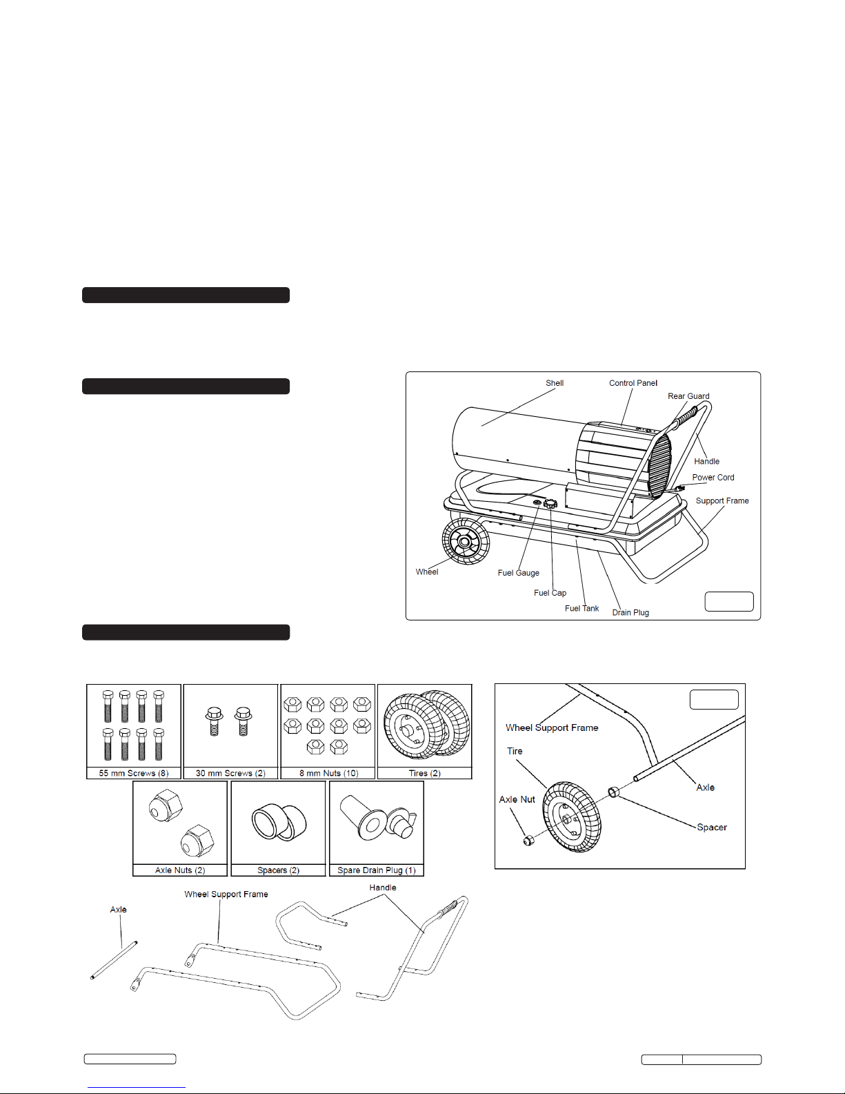
New design heaters are up to 50% quieter than traditional forced air models. Two heat settings allow for High and Low output enabling maximum
fuel efficiency. Proven pump system handles paraffin/kerosene or diesel without any modification and provides a cleaner more efficient
combustion. Fitted with top mounted touch pad panel, which allows easy and convenient control over the output and room thermostat
temperature. Fitted with many additional features, including digital room temperature (°C) display, code read out, heavy-duty solid wheels, fuel
tank gauge and heavy-duty filler cap. Suitable for ventilated areas like warehouses, garages and workshops.
DO NOT touch the heater outlet when in use, or for a period of time after it’s switched off, as these are VERY hot and will take time to cool
down.
DO NOT switch the heater off by disconnecting it from the mains. ALWAYS set the switch on the burner to the ‘OFF’ position and allow the
cooling cycle to finish, before disconnecting from the mains.
DO NOT use an external fuel tank. Only use the tank that is fitted to the heater, and only fill it when the heater has cooled down.
Ensure that the heater is correctly turned off.
When not in use for an extended period, store in a safe, dry area, out of reach of children.
Important: This appliance is not intended for persons (including children) with reduced physical, sensory or mental capabilities, or lack of
experience and knowledge, unless they have been given supervision or instruction concerning use of the appliance by a person responsible
for their safety. Children should be supervised to ensure that they do not play with the appliance.
WARNING!
This heater is not suitable for use with
Bio-Diesel; use of Bio-Diesel will damage the
lterandseals.Damagecausedbyuseof
Bio-Dieselwillnotbecoveredbywarranty.
2. INTRODUCTION
3. SPECIFICATION
Model No: ..........................AB1500Q
Output: .............................35/44kW
Output: .............................120,000/150,000Btu/hr
Tank Capacity: .......................39ltr
Fuel: . . . . . . . . . . . . . . . . . . . . . . . . . . . . . . .Parafn/Kerosene/Diesel
Supply: . . . . . . . . . . . . . . . . . . . . . . . . . . . . .230V-5A
Running Time per Filling(Maximum): ......11hrs
Transport Wheels: ....................Yes
Air Flow: ............................630cfm
Automatic Shut-Off: ...................Ye s
Heated Area:.........................30000ft³
Heated Area:.........................850m³
Weight: .............................33kg
Fig.1
Original Language Version
© Jack Sealey Limited
DO NOT allow untrained persons to operate the heater and DO NOT operate the heater without the safety guard.
DO NOT move or handle the heater when hot, without wearing protective gloves. Never move the heater whilst it is operating.
DO NOT leave the heater unattended for prolonged periods of time when in use. Switch the heater off and unplug from the mains
before leaving work area.
DO NOT fill the fuel tank whilst the heater is running or still hot. DO NOT over-fill the fuel container. Wipe up any spilt fuel immediately.
DO NOT obstruct the air inlet (rear) and air outlet (front) of the heater and DO NOT use duct work in front or at the rear of the heater.
DO NOT allow children or animals near the heater when in use, or whilst still hot.
WARNING! RISK OF ELECTRIC SHOCK. DO NOT expose the heater to water spray, rain, dripping water or wind.
DO NOT operate the heater when you are tired or under the influence of alcohol, drugs or intoxicating medication.
4. ASSEMBLY
4.1. Remove the heater and all the packaging from the carton. Note: make sure the axle is removed from the side of the polystyrene packaging.
4.2. Tools Required: cross head screwdriver, 8mm open ended spanner, 19mm open ended spanner.
4.3. Contents
Fig.2
AB1500Q Issue:2(I) - 19/02/15
Page 3

DANGER! Never refuel this heater while it is hot or operating. Fire or explosion could result. Never ll the fuel tank indoors, only outdoors
on a level suface. DO NOT overll the tank.
WARNING! Minimum distance from combustibles: Outlet 3 metres, Top/Sides/Rear 2 metres.
5.1. Ventilation
5.1.1. Risk of indoor air pollution and Carbon Monoxide poisoning. Not for indoor use. Indoor use only permitted for the temporary heating of
buildings under construction, alteration or repair.
5.1.2. Always provide a fresh air opening in the heated space. Provide a larger opening if more heaters are being used.
5.1.3. Minimum Ventilation Opening Needed: AB1500Q - 3760cm² (5.3ft²)
5.2. StartingtheHeater(Ignition)Refertog.4
5.2.1. Fill the tank with kerosene or other approved fuel until the needle on the fuel gauge points to "F".
5.2.2. Replace fuel cap and tighten rmly.
5.2.3. Connect the heater to a mains supply. You must use an extension lead that is at least 3 metres long and of a minimum of 14 AWG rating.
5.2.4. Press the power button to turn the heater on.
5.2.5. Select BTU output setting using BTU HI / LO buttons.
5.2.6. Select desired temperature using temperature HI / LO buttons.
5.2.7. The heater will ignite once the temperature setting is higher than the ambient temperature in the space.
Note: If the heater does not ignite, the thermostat may be set too low. Increase the temperature to a higher setting until the heater ignites.
Note: If the heater does not ignite, press power button to turn off the heater, check steps 1-3 above and press power button to power on the
heater. If the heater still does not ignite refer to "Troubleshooting Guide" see section 8.
5.3. Stopping / Restarting the Heater
5.3.1. To stop the heater, move the power switch to the "Off" position and unplug the mains cable.
5.3.2. To restart the heater wait 10 seconds and follow 5.2. "Starting the Heater" steps.
5. OPERATION
Original Language Version
© Jack Sealey Limited
Fig.3
Fig.4
Fig.5
Fig.6
4.4. Refertog.2
Insert axle through holes in wheel support.
4.5. Slide the spacers onto the axle, then slide the wheels onto the axle with the air
valves facing outwards. Use the axle nuts to hold them in place.
4.6. Refertog.3.
Place heater on wheel support frame and line up holes on the fuel tank lip.
4.7. Attach front handle with four long (55mm) screws and four nuts, through the second and
third holes from the front on both sides of the tank lip and tighten rmly.
4.8. Insert two short screws (30mm) through the rst hole in the front of the front handle and
tank lip. Fit nuts and tighten rmly.
4.9. Attach rear handle with 4 long screws (55mm) and four nuts through the rst and second
hole from the rear on both sides of the tank lip and the wheel support frame and tighten
rmly.
AB1500Q Issue:2(I) - 19/02/15
AB1500Q Issue:2(I) - 19/02/15
Page 4

Fig.7
Fig.8
6.3.4. Spark Plug: Clean and re-gap after every 600 hours of operation, or replace as needed. After removing the spark plug, clean the terminals
with a wire brush. Re-gap the terminals to 3.5mm (0.140"), see g.9.
6.3.5. Photocell: The photocell should be cleaned using a cotton swab dipped in alcohol or water at least once per heating season, or more
depending on conditions, see g.10.
Fig.9
Fig.10
Original Language Version
© Jack Sealey Limited
6.1. Long Term Storage
6.1.1. Drain the fuel in the bottom of the fuel tank.
6.1.2. To remove the drain plug, pull the plug grip downward and remove the seal head from the drain hole in the tank, See g.5.
6.1.3. Using a small amount of kerosene, rinse and swirl the inside of the fuel tank, empty the tank fully.
6.1.4. To replace the drain plug; push the drain head fully into the drain hole and secure by pushing the seal cap fully into the head hole.
(See g.6).
6.2. Service
6.2.1. DO NOT tamper with the unit. Return to a Sealey service agent.
6.3. Maintenance Schedule
6.3.1. Fuel/Fuel Tank: ush tank every 200 hours of operation or as needed, (refer to section 6.1). DO NOT ush with water, use fresh kerosene
only.
6.3.2. Fan Blades: Blades should be cleaned at least once per heating season, depending on conditions. Remove all accumulated dust and dirt
with a damp cloth, taking care not to bend any of the fan blades. Be sure the blades are dry before restarting the heater. For fan assembly
removal, see g.7.
6.3.3. Fuel Filter: The fuel lter should be cleaned at least twice per heating season. Clean the lter by rinsing it in clean kerosene. Contaminated
fuel could make cleaning the fuel lter necessary immediately.
To remove the lter turn the lter 90° anticlockwise.
6. MAINTENANCE
6.3.6 Nozzles: Nozzles should be cleaned or replaced at least once every heating season. Contaminated fuel could make this necessary
immediately. To clean dirt from the nozzle, blow compressed air through the nozzle front. It may be necessary to soak the nozzle in
kerosene to loosen any dirt particles, see g.11.
Fig.11
AB1500Q Issue:2(I) - 19/02/15
Page 5

Original Language Version
AB1500Q Issue:2(I) - 19/02/15
© Jack Sealey Limited
87 TROUBLESHOOTING
Although this heater operates with
diesel fuel, when the temperatures
are below 0°C, diesel additives are
required to maintain the diesel's
viscosity. Typically diesel can cloud
in freezing conditions and will start to
gel. You will need additives for your
fuel in these conditions.
Kerosene/Parafn does not start to
gel until the ambient temperature is
around -40°C.
Page 6

Environmental Protection
Recycle unwanted materials instead of disposing of them as waste. All tools, accessories and packaging should be
sorted, taken to a recycling centre and disposed of in a manner which is compatible with the environment.
When the product becomes completely unserviceable and requires disposal, drain off any fluids (if applicable)
into approved containers and dispose of the product and the fluids according to local regulations.
WEEE Regulations
Dispose of this product at the end of its working life in compliance with the EU Directive on
Waste Electrical and Electronic Equipment (WEEE). When the product is no longer required, it must be disposed
of in an environmentally protective way. Contact your local solid waste authority for recycling information.
NOTE: It is our policy to continually improve products and as such we reserve the right to alter data, specifications and component parts without prior notice.
IMPORTANT: No liability is accepted for incorrect use of this product.
WARRANTY: Guarantee is 12 months from purchase date, proof of which will be required for any claim.
01284 757500
01284 703534
sales@sealey.co.uk
Sole UK Distributor, Sealey Group,
Kempson Way, Suffolk Business Park,
Bury St. Edmunds, Suffolk,
IP32 7AR
www.sealey.co.uk
Original Language Version
AB1500Q Issue:2 (I) - 19/02/15
© Jack Sealey Limited
 Loading...