

Page 1
Sealevel Systems, Inc.
Sealevel.com
Phone 864.843.4343
Page 2

©Sealevel Systems, Inc.
SL9249 – 12/2013
7802e Manual
2
Introduction .................................................................................................................................. 3
Before You Get Started ............................................................................................................... 4
What’s Included ................................................................................................................ 4
Advisory Conventions ...................................................................................................... 4
Optional Items .................................................................................................................. 5
Hardware Description.................................................................................................................. 6
PCI EXPRESS BOARD .......................................................................................................... 6
68PIN BOARD CONNECTOR ............................................................................................. 6
DB9M SERIAL CONNECTORS ............................................................................................ 6
ADDRESS AND IRQ SELECTION......................................................................................... 7
CLOCK MODES .................................................................................................................. 7
BAUD RATES ...................................................................................................................... 7
ELECTRICAL INTERFACE SELECTION ................................................................................ 8
LINE TERMINATION ........................................................................................................... 8
RS-485 ‘ECHO’ .................................................................................................................. 8
Software Installation .................................................................................................................. 10
WHERE TO GET SEALEVEL SOFTWARE ............................................................................ 10
WINDOWS INSTALLATION ............................................................................................... 10
GUIDED SOFTWARE INSTALLATION ............................................................................... 11
MANUAL SOFTWARE INSTALLATION .............................................................................. 13
UPGRADING TO THE CURRENT SEACOM DRIVER .......................................................... 14
LINUX SUPPORT ............................................................................................................... 14
Technical Description ................................................................................................................ 15
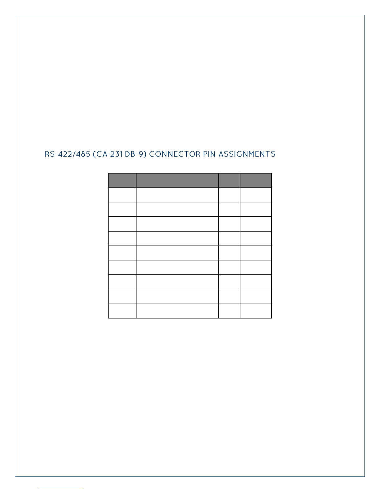
RS-422/485 (CA-231 DB-9) CONNECTOR PIN ASSIGNMENTS ...................................... 15
Specifications ............................................................................................................................. 17
Appendix A – Troubleshooting .................................................................................................. 18
Appendix B - Handling Instructions .......................................................................................... 19
Appendix C - Electrical Interface ............................................................................................. 20
Appendix D - Asynchronous Communications ........................................................................ 21
Appendix E – Mechanical Drawing ........................................................................................... 22
Warranty ..................................................................................................................................... 23
Page 3

©Sealevel Systems, Inc.
SL9249 – 12/2013
7802e Manual
3
Introduction
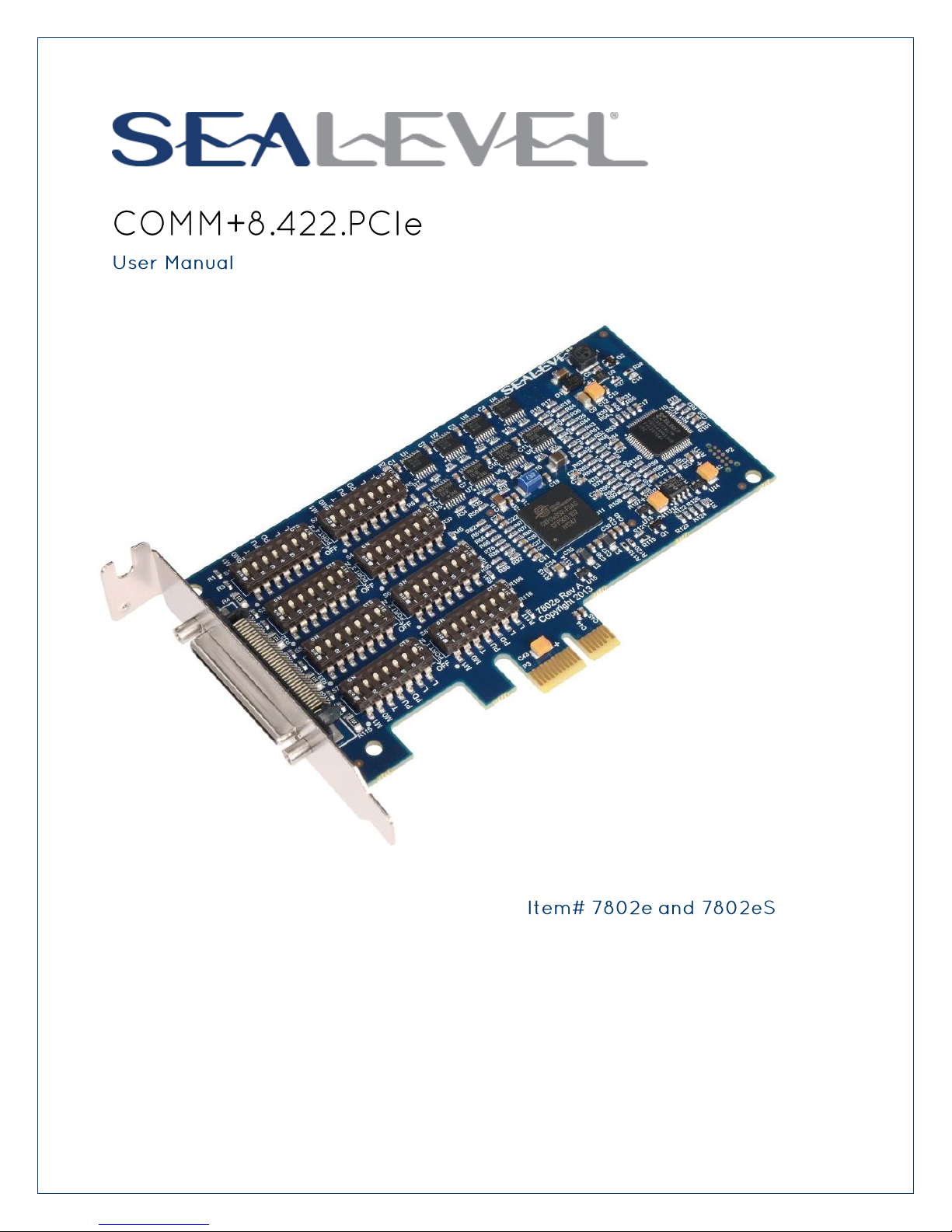
The Sealevel COMM+8.422.PCIe (Item# 7802e) provides a PCI Express 1.0a compliant interface
adapter with eight asynchronous serial ports for industrial automation and control applications.
The serial ports are field selectable for RS-422 or RS-485 and support data rates to 921.6 Kbps.
RS-422 mode for is designed for long distance device connections up to 4000ft. where noise
immunity and high data integrity are essential. RS-485 mode can capture data from multiple
peripherals in an RS-485 multi-drop network. Up to 31 unit load RS-485 devices can be
connected to each port to automate your data collection. You can even mix the ports in any of
the interface combinations to provide maximum flexibility to your application.
In RS-485 mode, the transmitter is automatically enabled in hardware, eliminating the need for
application software control. This allows the 7802e to be used with standard serial
communications applications and removes the risk of bus contention and data corruption. The
Sealevel SeaCOM software driver and utilities make installation and operation easy XP, Vista,
Windows 7, and Windows 8 operating systems.
The 7802e ships with a low profile PC bracket for use in systems with a low profile PCI Express
slot. If you need a standard size PC bracket, order the 7802eS.
PCI Express eight-port serial interface adapter
Each port individually configurable for RS-422 or RS-485
High performance OXPCIe954 UART with 128-byte FIFOs
Each port supports data rates to 921.6K bps
Oscillator and clock prescaler support wide range of baud rates
Supports 9-bit protocol framing
PCI Express 1.0a compliant via X1 connector
Compatible with all low profile and standard size PCI Express slots
Includes 36” cable that terminates to eight DB9M connectors
Automatic RS-485 enable/disable
Page 4

©Sealevel Systems, Inc.
SL9249 – 12/2013
7802e Manual
4
Before You Get Started
The COMM+8.422.PCIe is shipped with the following items. If any of these items are missing or
damaged, please contact Sealevel for replacement.
COMM+8.422.PCIe Serial I/O Adapter – Four-Port 422/485 Serial Interface
7802e – PCI Express Board with Low Profile PC Bracket
7802eS – PCI Express Board with Standard Height PC Bracket
CA231 – 68 pin Male to (8) DB9 Male Cable
Sealevel Software CD – SeaCOM software and user manual
Warning - The highest level of importance used to stress a condition where damage
could result to the product or the user could suffer serious injury.
Important – The middle level of importance used to highlight information that might
not seem obvious or a situation that could cause the product to fail.
Note – The lowest level of importance used to provide background information,
additional tips, or other non-critical facts that will not affect the use of the product.
Page 5

©Sealevel Systems, Inc.
SL9249 – 12/2013
7802e Manual
5
Depending upon your application, you are likely to find one or more of the following items
Terminal Block Kit (Item# KT106)
Terminal Block Kit - TB06 + (2) CA127 Cables
Terminal Block Kit (Item# KT105)
Terminal Block Kit - TB05 + CA127 Cable
Terminal Block Kit (Item# TB34-8)
Terminal Block Kit (8 Pack) - DB9 Female to 5 Screw
Terminals (RS-422/485)
useful with the COMM+8.422.PCIe. All items can be purchased from our website
(www.sealevel.com) by calling our sales team at (864) 843-4343.
Page 6

©Sealevel Systems, Inc.
SL9249 – 12/2013
7802e Manual
6
Hardware Description
The 7802e is a low profile PCI Express 1.0a compliant board via single-lane x1 slot. It can be
used in any single- or multi-lane PCI Express slot. It is available in standard height PCI Express
as item# 7802eS.
The board integrates a 68 pin female connector for interfacing the serial ports via the included
cable.
The 7802e ships with an eight-port cable (Item# CA231) that includes eight DB9 male serial
connectors. The pin out for these connectors is detailed in the following Technical Description
section.
Page 7

©Sealevel Systems, Inc.
SL9249 – 12/2013
7802e Manual
7
Hardware Configuration
For This Data Rate
Clock Prescaler
Choose This Divisor DLM:DLL
1200 bps
3.625
898
2400 bps
3.625
449
4800 bps
1.875
434
9600 bps
1.875
217
19.2K bps
1.375
148
38.4K bps
1.375
74
57.6K bps
22.625
3
115.2K bps
1
34
230.4K bps
1
17
460.8K bps
2.125
4
921.6K bps
2.125
2
The COMM+8.422.PCIe is automatically assigned I/O addresses and IRQs by your motherboard
BIOS or by a ‘Plug-n-Play’ Operating System. Adding or removing other hardware or moving the
adapter to another slot may change the assignment of I/O addresses and IRQs.
The COMM+8.422.PCIe derives a 62.5MHz clock from the PCI express link which is divided by a
8 bit clock prescaler and a 16 bit clock divisor to provide a wide range of possible baud rates.
Note that there are many combinations that can give the same result (e.g. Prescaler=1 and
Divisor = 8, Prescaler =2 and Divisor = 4, or Prescaler=8 and Divisor = 1). As long as the
calculated data rate is within +/- 2% you should communicate fine.
The following table shows some common data rates and the rates you should choose to achieve
them when using the COMM+8.422.PCIe.
Page 8

©Sealevel Systems, Inc.
SL9249 – 12/2013
7802e Manual
8
Each of the eight ports on the COMM+8.422.PCIe can be individually configured as an RS-422,
Switch 1 (Silk M1)
Switch 2 (Silk M0)
Mode Select
OFF
OFF
RESERVED
OFF
ON
422
ON
OFF
485 With Echo
ON
ON
485 No Echo
Switch
Name
Function
3
T
Adds or removes the 120 ohm termination.
4
PU
Adds or removes the 1K ohm pull-up resistor in the RS-422/RS-485 receiver circuit
5
PD
Adds or removes the 1K ohm pull-down resistor in the RS-422/RS-485 receiver circuit
6
L
Connects the TX- to RX- for RS-485 two-wire operation.
7
L
Connects the TX+ to RX+ for RS-485 two-wire operation.
or RS-485 interface. This is selectable via the port DIP-switch, each is labeled with its port
number.
Typically, each end of the RS-485 bus must have line-terminating resistors (RS-422 terminates
at the receive end only). A 120-ohm resistor is across each RS-422/485 input in addition to a
1K-ohm pull-up/pull-down combination that biases the receiver inputs. Each switch allows
customization of this interface to specific requirements. Each switch position corresponds to a
specific portion of the interface. If multiple COMM+8.422.PCIe adapters are configured in an RS485 network, only the boards on each end should have switches T, P & P ON. Refer to the
following table for each position’s operation:
In ‘RS-485 With Echo’ mode both the receiver and the transmitter are enabled simultaneously.
Every time a character is transmitted; it is also received. This can be beneficial if the software
can handle echoing (i.e. using received characters to throttle the transmitter) or it can confuse
the system if the software does not. An RS-485 ‘No Echo’ option is selected by placing both
Mode switches (M0, M1) in the ‘On’ position.
Page 9
©Sealevel Systems, Inc.
SL9249 – 12/2013
7802e Manual
9
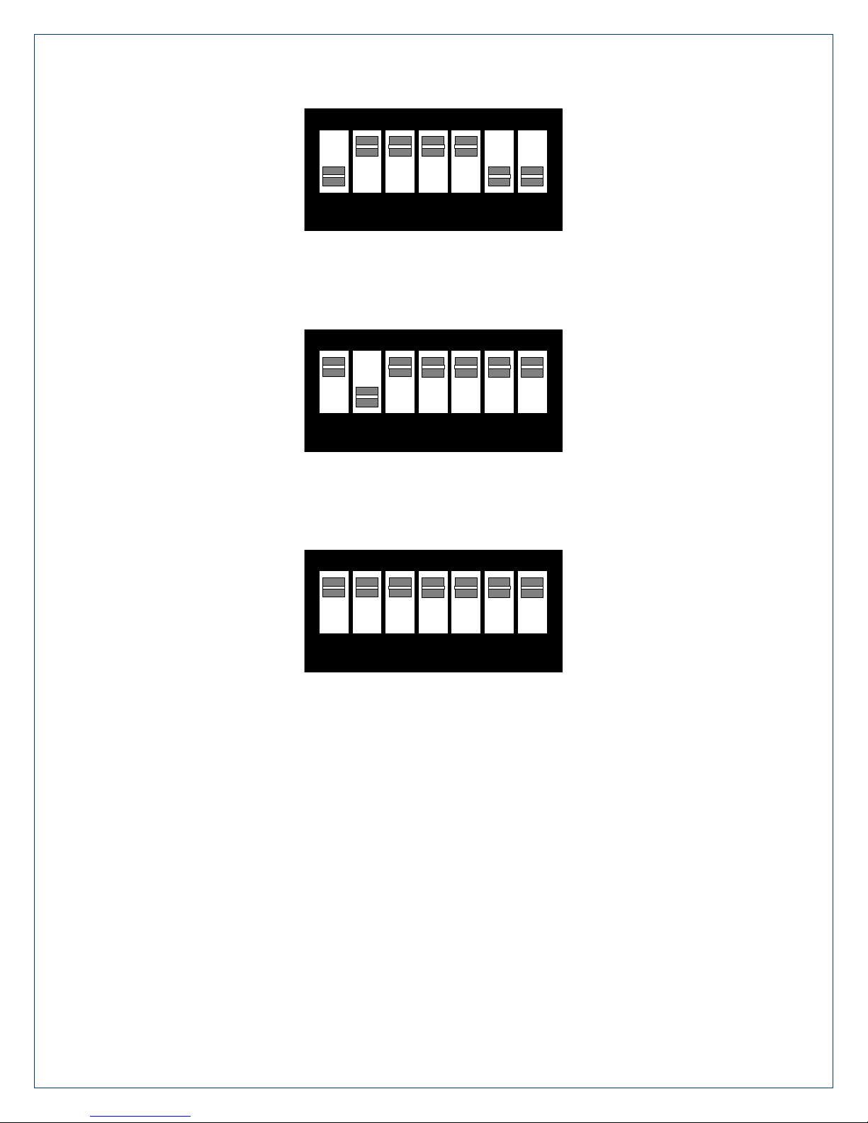
1 2 3 4 5 6 7
ON
1 2 3 4 5 6 7
ON
1 2 3 4 5 6 7
ON
Figure 1 - RS-422 Mode
Figure 2 - RS-485 2-wire with 'Echo'
Figure 3 - RS-485 2-wire, No 'Echo'
Page 10
©Sealevel Systems, Inc.
SL9249 – 12/2013
7802e Manual
10
Software Installation
This section contains helpful information pertaining to the installation of supported Sealevel
Systems, Inc. software packages. First, the process of acquiring the software is discussed.
Next, the installation is detailed in a step-by-step guide for Windows and Linux operating
systems.
All Sealevel products are shipped with media containing the installers for each software
package available. If the media is otherwise unavailable or if desired, the current versions of
Sealevel software packages can be obtained from the Sealevel website (see following
instructions). If you already have the Sealevel software, proceed to the Windows or Linux
installation section.
Sealevel software for Windows and Linux operating systems is available at these links:
o Software for Windows
o Software for Linux
Choose the link for the desired software package and click on the ‘Download File’ link to
download the current driver.
Proceed to the Manual Software Installation guide for your operating system.
Do not connect the hardware until the software has been successfully installed. To
install Sealevel software, you must log in as an administrator or have administrator
privileges in Windows.
To install Sealevel software, you must log in as an administrator or have administrator
privileges in Windows.
Page 11

©Sealevel Systems, Inc.
SL9249 – 12/2013
7802e Manual
11
1. Insert the Sealevel media into your PC.
2. If the ‘AutoRun’ feature is enabled for this media the software will automatically
launch.
3. Otherwise, navigate to the root directory of the media and double-click the
‘autorun.exe’ application to launch the installation window.
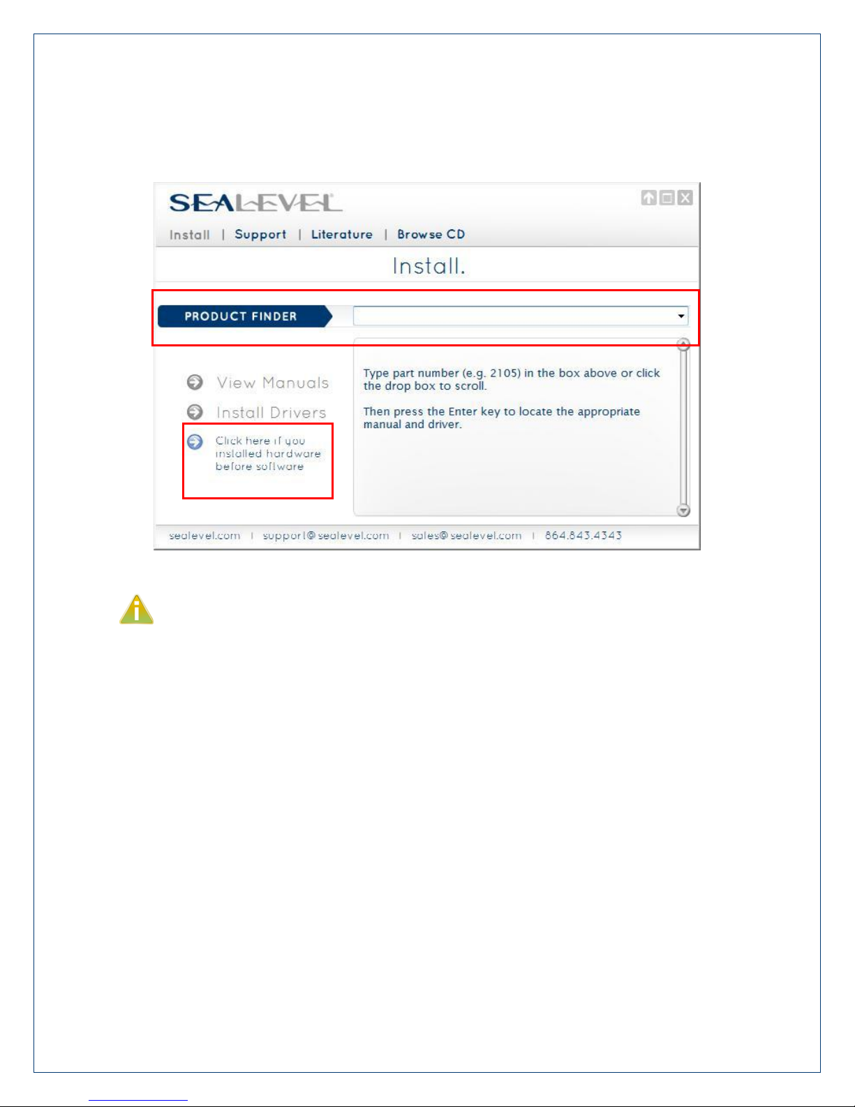
4. Select ‘Install’ as demonstrated in the image below.
Page 12
©Sealevel Systems, Inc.
SL9249 – 12/2013
7802e Manual
12
5. Type the part number for your adapter in the text box and press the ‘Enter’ key,
or click on the drop box to scroll from the listing to select your product.
If you installed your hardware prior to loading/installing the software, please click on
the ‘Click here if you installed hardware before software’ link and follow the listed
instructions.
6. Click the ‘Install Drivers’ button to launch the Installation Wizard.
7. When the InstallShield Wizard’ window appears, click the ‘Next’ button to initiate
the software installation.
8. When the ‘License Agreement’ window appears, accept the terms and click ‘Next’
to continue. You can click the ‘Print’ button to print out a copy of the agreement
for your records. If you do not accept the terms of the agreement, the
installation will stop.
9. When the ‘Ready to Install the Program’ window appears, click the ‘Install’ button
to install the software onto the hard drive of your computer. The files will be
automatically installed into the ‘C:\Program Files’ folder on your computer.
Some versions of Windows will halt the installation and provide you with a dialog
box that will ask you for permission for the installer to make changes to your
computer. Click on the ‘Allow’ button to continue installation of your Sealevel
Page 13
©Sealevel Systems, Inc.
SL9249 – 12/2013
7802e Manual
13
software.
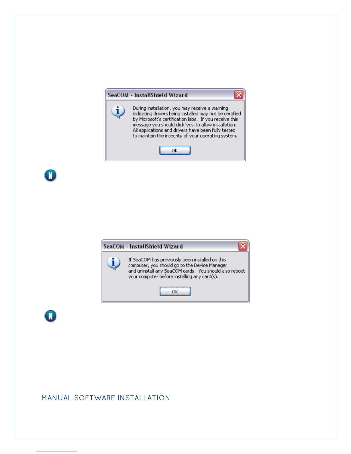
10. The following dialog box may appear, as shown below. Click the ‘OK’ button to
continue.
All Sealevel Systems software drivers have been fully tested by Sealevel. Clicking ‘OK’
will not harm your system.
11. The following dialog box may appear, as shown below. Click the ‘OK’ button to
continue.
This is a notification that if you are upgrading from a previous driver version, you
should remove the associated Device Manager hardware entries and reinstall the adapter
after the installing the SeaCOM software.
12. The setup file will automatically detect the operating environment and install the
proper components. Next follow the information presented on the screens that
follow. Once the installation is complete, close the disk installation window.
13. Refer to the Physical Installation section to connect and install your adapter.
Page 14

©Sealevel Systems, Inc.
SL9249 – 12/2013
7802e Manual
14
1. To install a software package from the Sealevel media; browse the Sealevel Systems
media ’Software’ directory. For example: Software\SeaCOM\Windows\SeaCOM
Installer.exe
2. If you are using Windows Vista or newer operating systems, right click on the
installer executable and choose ’Run as Administrator’. If you are using an operating
system prior to Windows Vista, double click on the executable to launch the
InstallShield and initiate the driver installation.
3. Please refer to step six above in the Guided Software Installation section and follow
the remaining installation steps.
1. Download the current driver using the Instructions from the Where to Get Software
section above. Please take note of the destination directory it will save to.
2. Uninstall the currently loaded driver SeaCOM driver found in the Control Panel. Prior
to Windows Vista SeaCOM will be populated in ‘Add/Remove Programs’ list. In Vista
and newer OSs it will be found in the ‘Programs and Features’ list.
3. Navigate to the Device Manager and remove the Sealevel adapter by right clicking on
the line item choosing ‘Uninstall’. Depending on your product, it can be found under
either ‘Multiport Serial adapters’ or ‘Universal Serial Bus controllers’.
4. In the Device Manager under ‘Action’, choose ‘Scan for Hardware changes’. This will
prompt the installation of the adapter and associate it with the newly installed
SeaCOM driver.
The 7802e is supported natively in Linux kernels 2.6.28 and later.
Page 15
©Sealevel Systems, Inc.
SL9249 – 12/2013
7802e Manual
15
Technical Description
Signal
Name
Pin #
Mode
GND
Ground 5
TX +
Transmit Data Positive
4
Output
TX-
Transmit Data Negative
3
Output
RTS+
Request To Send Positive
6
Output
RTS-
Request To Send Negative
7
Output
RX+
Receive Data Positive
1
Input
RX-
Receive Data Negative
2
Input
CTS+
Clear To Send Positive
9
Input
CTS-
Clear To Send Negative
8
Input
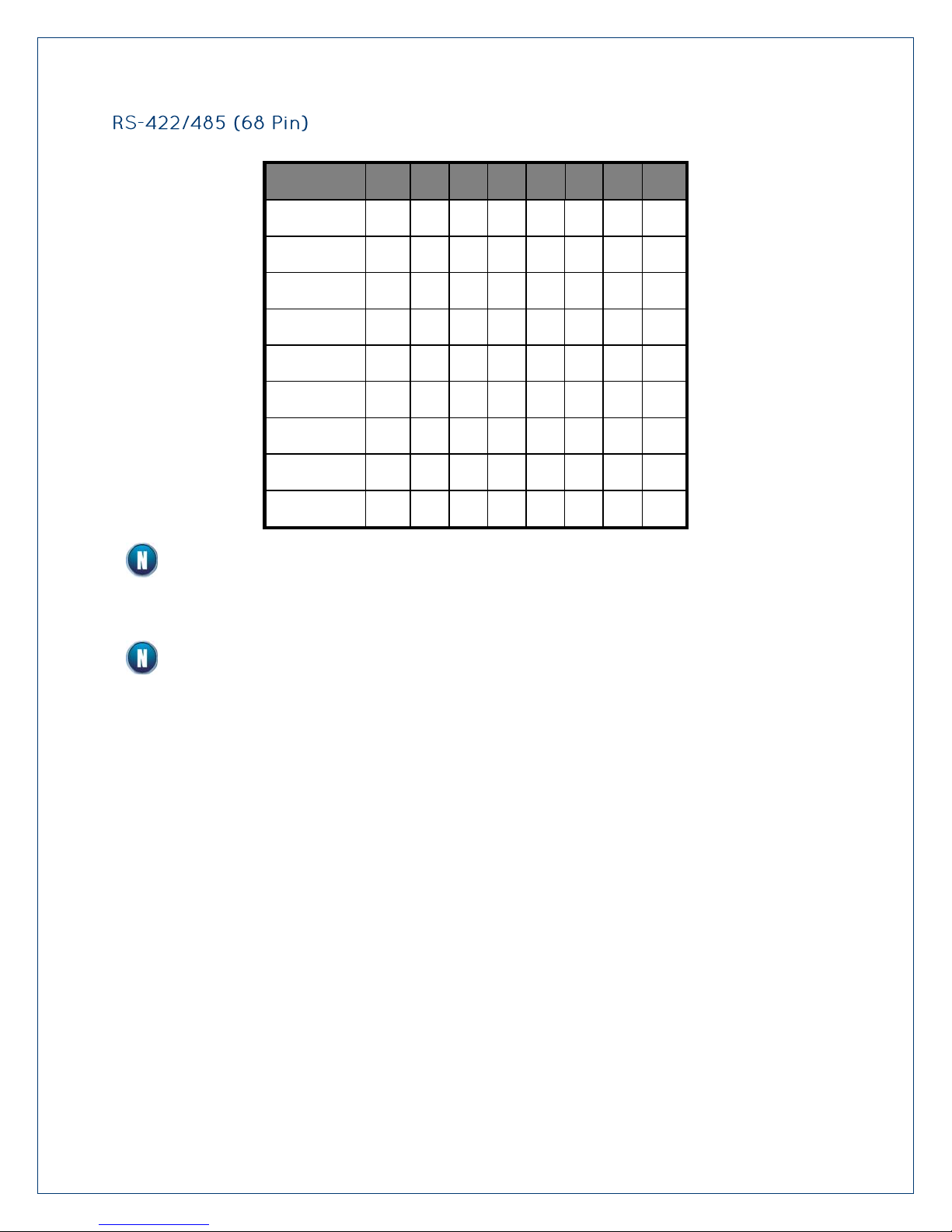
The COMM+8.422.PCIe provides eight RS-422/485 ports from a single PCIe slot.
The COMM+8.422.PCIe utilizes the OXPCIe954 UART. This chip features programmable baud
rates, data format, interrupt control and industry leading 128-byte transmit and receive FIFOs.
The UARTs are register compatible with 16C450, 16C550, 16C654 and 16C750 UARTs. The
FIFO depth can be changed to match the depth of these UARTs.
Page 16
©Sealevel Systems, Inc.
SL9249 – 12/2013
7802e Manual
16
Port #
1 2 3 4 5 6 7
8
TX-
1 9 19
27
35
43
53
61
RX-
7
15
25
33
41
49
59
67
RTS-
5
13
23
31
39
47
57
65
CTS-
8
16
26
34
42
50
60
68
TX+
4
12
22
30
38
46
56
64
RTS+
6
14
24
32
40
48
58
66
RX+
3
11
21
29
37
45
55
63
CTS+
2
10
20
28
36
44
54
62
GND
17
17
18
18
51
51
52
52
Please terminate any control signals that are not going to be used. The most common
way to do this is connect RTS to CTS and RI. Also, connect DCD to DTR and DSR.
Terminating these pins, if not used, will help ensure you get the best performance from
your adapter.
The RTS output is only available in RS-422 mode. The RTS output is tri-stated in RS-485
mode and therefore unusable. The CTS input is available in all modes.
Page 17

©Sealevel Systems, Inc.
SL9249 – 12/2013
7802e Manual
17
Specifications
Specification
Operating
Storage
Temperature Range
0º to 70º C
(32º to 158º F)
-50º to 105º C
(-58º to 221º F)
Humidity Range
10 to 90% R.H.
Non-Condensing
10 to 90% R.H.
Non-Condensing
Supply line
+3.3VDC
+12VDC
Rating
100 mA
25 mA
All Sealevel Systems Printed Circuit boards are built to UL 94V0 rating and are 100% electrically
tested. These printed circuit boards are solder mask over bare copper.
Page 18

©Sealevel Systems, Inc.
SL9249 – 12/2013
7802e Manual
18
Appendix A – Troubleshooting
1. Identify all I/O adapters currently installed in your system. This includes your on-
board serial ports, controller cards, sound cards etc. The I/O addresses used by
these adapters, as well as the IRQ (if any) should be identified.
2. Configure your Sealevel Systems adapter so that there is no conflict with currently
installed adapters. No two adapters can occupy the same I/O address.
3. Make sure the Sealevel Systems adapter is using a unique IRQ. While the Sealevel
Systems adapter does allow the sharing of IRQs, many other adapters (i.e. SCSI
adapters & on-board serial ports) do not. The IRQ is typically selected by the BIOS or
operating system. Some BIOS setup software will allow changing the IRQ, but others
do not. Another method of changing assigned resources is to try changing PCIe
slots. This will typically cause the BIOS or OS to reassign the resources.
4. Make sure the Sealevel Systems adapter is securely installed in a motherboard slot.
5. The diagnostic tool ‘WinSSD’ is installed in the SeaCOM folder on the Start Menu
during the setup process. First find the ports using the Device Manager, then use
‘WinSSD’ to verify that the ports are functional.
6. Always use the Sealevel Systems diagnostic software when troubleshooting a
problem. This will eliminate any software issues from the equation.
Page 19

©Sealevel Systems, Inc.
SL9249 – 12/2013
7802e Manual
19
Appendix B - Handling Instructions
A sudden electrostatic discharge can destroy sensitive components. Proper packaging
and grounding rules must therefore be observed. Always take the following precautions:
Transport boards and cards in electrostatically secure containers or bags.
Keep electrostatically sensitive components in their containers, until they arrive at an
electrostatically protected workplace.
Only touch electrostatically sensitive components when you are properly grounded.
Store electrostatically sensitive components in protective packaging or on anti-static
mats.
The following measures help to avoid electrostatic damages to the device:
Cover workstations with approved antistatic material. Always wear a wrist strap
connected to a properly grounded workplace.
Use antistatic mats, heel straps, and/or air ionizers for more protection.
Always handle electrostatically sensitive components by their edge or by their casing.
Avoid contact with pins, leads, or circuitry.
Turn off power and input signals before inserting and removing connectors or
connecting test equipment.
Keep work area free of non-conductive materials such as ordinary plastic assembly aids
and Styrofoam.
Use field service tools such as cutters, screwdrivers, and vacuum cleaners that are
conductive.
Page 20

©Sealevel Systems, Inc.
SL9249 – 12/2013
7802e Manual
20
Appendix C - Electrical Interface
The RS-422 specification defines the electrical characteristics of balanced voltage digital
interface circuits. RS-422 is a differential interface that defines voltage levels and driver/receiver
electrical specifications. On a differential interface, logic levels are defined by the difference in
voltage between a pair of outputs or inputs. In contrast, a single ended interface, for example
RS-232, defines the logic levels as the difference in voltage between a single signal and a
common ground connection. Differential interfaces are typically more immune to noise or
voltage spikes that may occur on the communication lines. Differential interfaces also have
greater drive capabilities that allow for longer cable lengths. RS-422 is rated up to 10 Megabits
per second and can have cabling 4000 feet long. RS-422 also defines driver and receiver
electrical characteristics that will allow 1 driver and up to 32 receivers on the line at once.
RS-422 signal levels range from 0 to +5 volts. RS-422 does not define a physical connector.
RS-485 is backwardly compatible with RS-422; however, it is optimized for party line or
multi-drop applications. The output of the RS-422/485 driver is capable of being Active
(enabled) or Tri-State (disabled). This capability allows multiple ports to be connected in a
multi-drop bus and selectively polled. RS-485 allows cable lengths up to 4000 feet and data
rates up to 10 Megabits per second. The signal levels for RS-485 are the same as those defined
by RS-422. RS-485 has electrical characteristics that allow for 32 drivers and 32 receivers to be
connected to one line. This interface is ideal for multi-drop or network environments. RS-485
tri-state driver (not dual-state) will allow the electrical presence of the driver to be removed
from the line. Only one driver may be active at a time and the other driver(s) must be tri-stated.
Page 21
©Sealevel Systems, Inc.
SL9249 – 12/2013
7802e Manual
21
Remain Idle or
next start bit
Odd, Ev en
or
Unused
STOP
P
BIT
5 to 8 Data Bits
Idle state of
line
1
0
1
1.5
2
Appendix D - Asynchronous Communications
Serial data communications implies that individual bits of a character are transmitted
consecutively to a receiver that assembles the bits back into a character. Data rate, error
checking, handshaking, and character framing (start/stop bits) are pre-defined and must
correspond at both the transmitting and receiving ends.
Asynchronous communications is the standard means of serial data communication for PC
compatibles and PS/2 computers. The original PC was equipped with a communication or COM:
port that was designed around an 8250 Universal Asynchronous Receiver Transmitter (UART).
This device allows asynchronous serial data to be transferred through a simple and
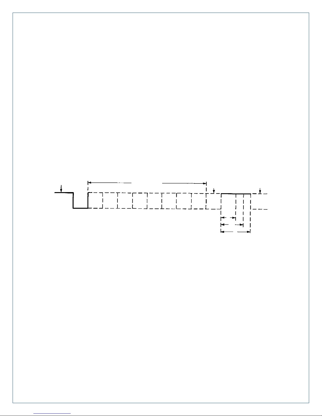
straightforward programming interface. A starting bit followed by a pre-defined number of data
bits (5, 6, 7, or 8) defines character boundaries for asynchronous communications. The end of
the character is defined by the transmission of a pre-defined number of stop bits (usually 1, 1.5
or 2). An extra bit used for error detection is often appended before the stop bits.
Figure 1 - Asynchronous Communications Bit Diagram
This special bit is called the parity bit. Parity is a simple method of determining if a data bit has
been lost or corrupted during transmission. There are several methods for implementing a
parity check to guard against data corruption. Common methods are called (E)ven Parity or
(O)dd Parity. Sometimes parity is not used to detect errors on the data stream. This is referred
to as (N)o parity. Because each bit in asynchronous communications is sent consecutively, it is
easy to generalize asynchronous communications by stating that each character is wrapped
(framed) by pre-defined bits to mark the beginning and end of the serial transmission of the
character. The data rate and communication parameters for asynchronous communications
have to be the same at both the transmitting and receiving ends. The communication
parameters are baud rate, parity, number of data bits per character, and stop bits (i.e.
9600,N,8,1).
Page 22
©Sealevel Systems, Inc.
SL9249 – 12/2013
7802e Manual
22
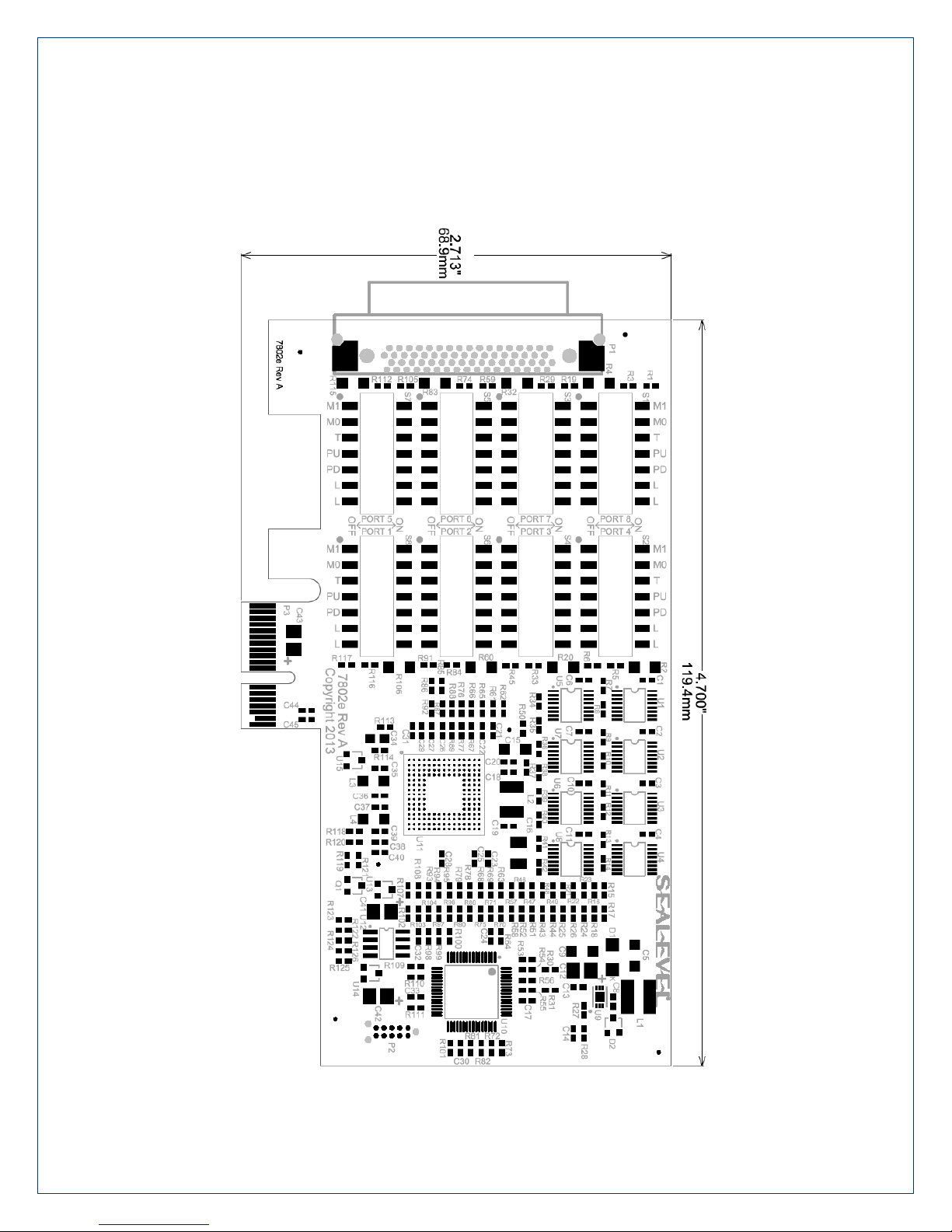
Appendix E – Mechanical Drawing
Page 23

©Sealevel Systems, Inc.
SL9249 – 12/2013
7802e Manual
23
Warranty
Sealevel's commitment to providing the best I/O solutions is reflected in the Lifetime Warranty
that is standard on all Sealevel manufactured I/O products. Relio™ industrial computers are
warranted for a period of two years and the R9 family is warranted for a five year period from
date of purchase. We are able to offer this warranty due to our control of manufacturing quality
and the historically high reliability of our products in the field. Sealevel products are designed
and manufactured at its Liberty, South Carolina facility, allowing direct control over product
development, production, burn-in and testing. Sealevel achieved ISO-9001:2008 certification in
2011.
Sealevel Systems, Inc. (hereafter "Sealevel") warrants that the Product shall conform to and
perform in accordance with published technical specifications and shall be free of defects in
materials and workmanship for the warranty period. In the event of failure, Sealevel will repair
or replace the product at Sealevel's sole discretion. Failures resulting from misapplication or
misuse of the Product, failure to adhere to any specifications or instructions, or failure resulting
from neglect, abuse, accidents, or acts of nature are not covered under this warranty.
Warranty service may be obtained by delivering the Product to Sealevel and providing proof of
purchase. Customer agrees to insure the Product or assume the risk of loss or damage in
transit, to prepay shipping charges to Sealevel, and to use the original shipping container or
equivalent. Warranty is valid only for original purchaser and is not transferable.
This warranty applies to Sealevel manufactured Product. Product purchased through Sealevel
but manufactured by a third party will retain the original manufacturer's warranty.
Products returned due to damage or misuse and Products retested with no problem found are
subject to repair/retest charges. A purchase order or credit card number and authorization
must be provided in order to obtain an RMA (Return Merchandise Authorization) number prior
to returning Product.
If you need to return a product for warranty or non-warranty repair, you must first obtain an
RMA number. Please contact Sealevel Systems, Inc. Technical Support for assistance:
Sealevel Systems, Incorporated acknowledges that all trademarks referenced in this manual are
the service mark, trademark, or registered trademark of the respective company.
 Loading...