

User Guide
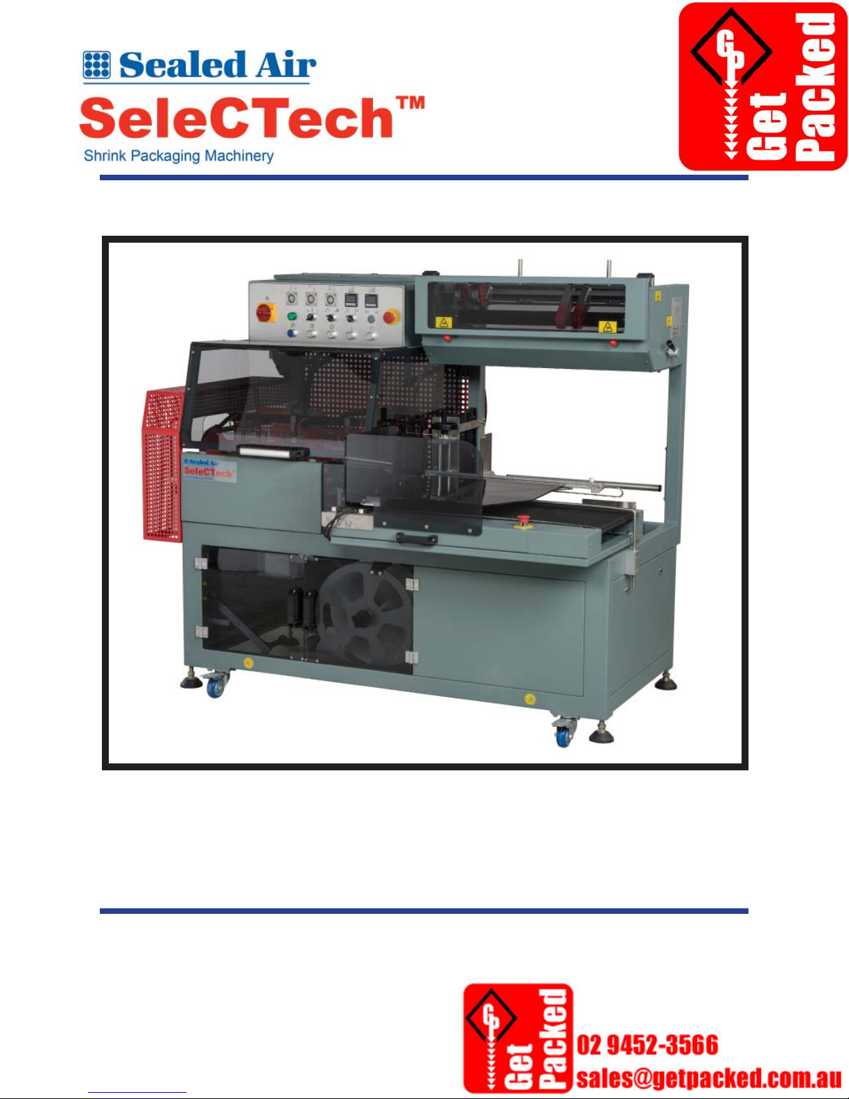
Sealing Machine SLCT-FAL5645

SeleCTech™
Model SLCT-FAL5645
Sealing Machine
This manual is a comprehensive reference for the SeleCTech™ Model SLCT-FAL5645
Sealing Machine. It includes information on machine specifi cations, safety, parts ordering,
system setup, operation, general maintenance, and general troubleshooting.
Table of Contents
SECTION A. SPECIFICATIONS ....................................................................A-1
SECTION 1. GENERAL INFORMATION ....................................................1-1
SECTION 2. INSTALLATION .......................................................................2-1
SECTION 3. OPERATION .............................................................................. 3-1
SECTION 4. GENERAL MAINTENANCE & TROUBLESHOOTING .....4-1
SECTION 5. REFERENCE DOCUMENTS ................................................... 5-1
This manual has been designed to serve as a reference guide for the SeleCTech™ Model
SLCT-FAL5645 Sealing Machine.
NOTICE
Copyright 2013 by Sealed Air Corporation (US). All rights reserved.
Sealed Air® and the 9 Dot Logo are registered trademarks of Sealed Air Corporation.
This document is copyrighted. The material contained herein is protected under the US Copyright Act of 1976.
This document, in whole or in part, may not be copied, photocopied, reproduced, translated or reduced to any
electronic or machine-readable form without the prior written permission of Sealed Air Corporation (US).
Manufactured in China exclusively for Sealed Air
Technology Enhanced by Shanklin® Engineering
Sealed Air Corporation assumes no responsibility for any errors that may appear in this document.

Section A. General Information
SLCT-FAL5645 Sealing Machine
SECTION A. SPECIFICATIONS
This section details information about machine specifi cations and machine parts illustrations.
A.1 SEALING MACHINE SPECIFICATIONS
A.1 SEALING MACHINE SPECIFICATIONS ................................. A-3
A.2 ILLUSTRATION OF MACHINE PARTS ...................................A-4
© Sealed Air Corporation (US)
MM-0110; Revision 1-A: 11/01/2013
A-1
Section A. General Information
SLCT-FAL5645 Sealing Machine
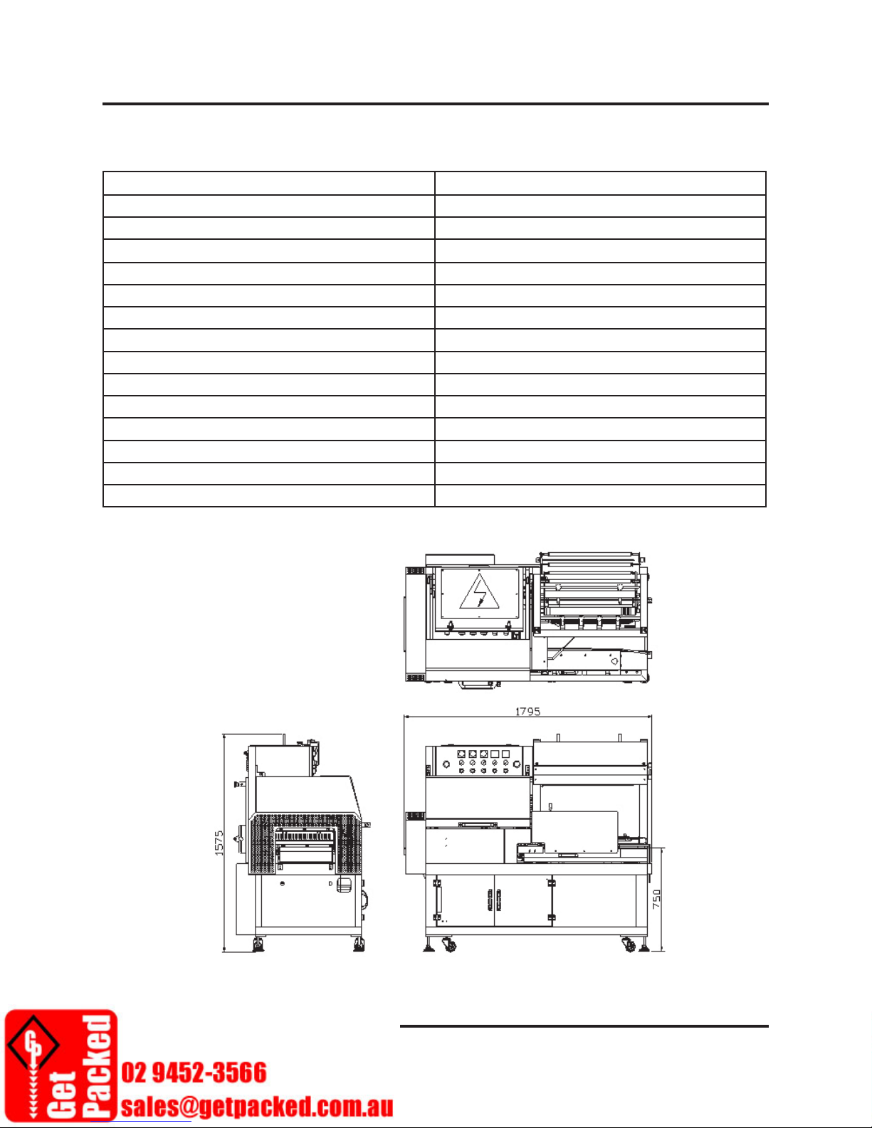
A.1 SEALING MACHINE SPECIFICATIONS
Specifi cation Description
Machine dimensions (L) x (W) x (H) 1795 mm x 985 mm x 1570 mm
Packing dimensions (L) x (W) x (H) (100~450) x mm x (60~350) mm x (5~120 ) mm
Sealing bars size (L) x (H) 565 mm x 460 mm
Packing fi lm 23 in
Packing capacity 30 pcs/min
Conveyor speed 26 m/min
Film POF, PE
Sealing blade temperature 180°C to 230°C
Voltage 240 V/1P 3 kW
Motor power 320 W
Electric power 2.5 KW
Weight 330 kg
Pressure 4 kg
Noise Emission 70 dB(A)
Figure A–1 Sealing Machine Dimensions
© Sealed Air Corporation (US)
MM-0110; Revision 1-A: 11/01/2013
A-3
Section A. General Information
SLCT-FAL5645 Sealing Machine
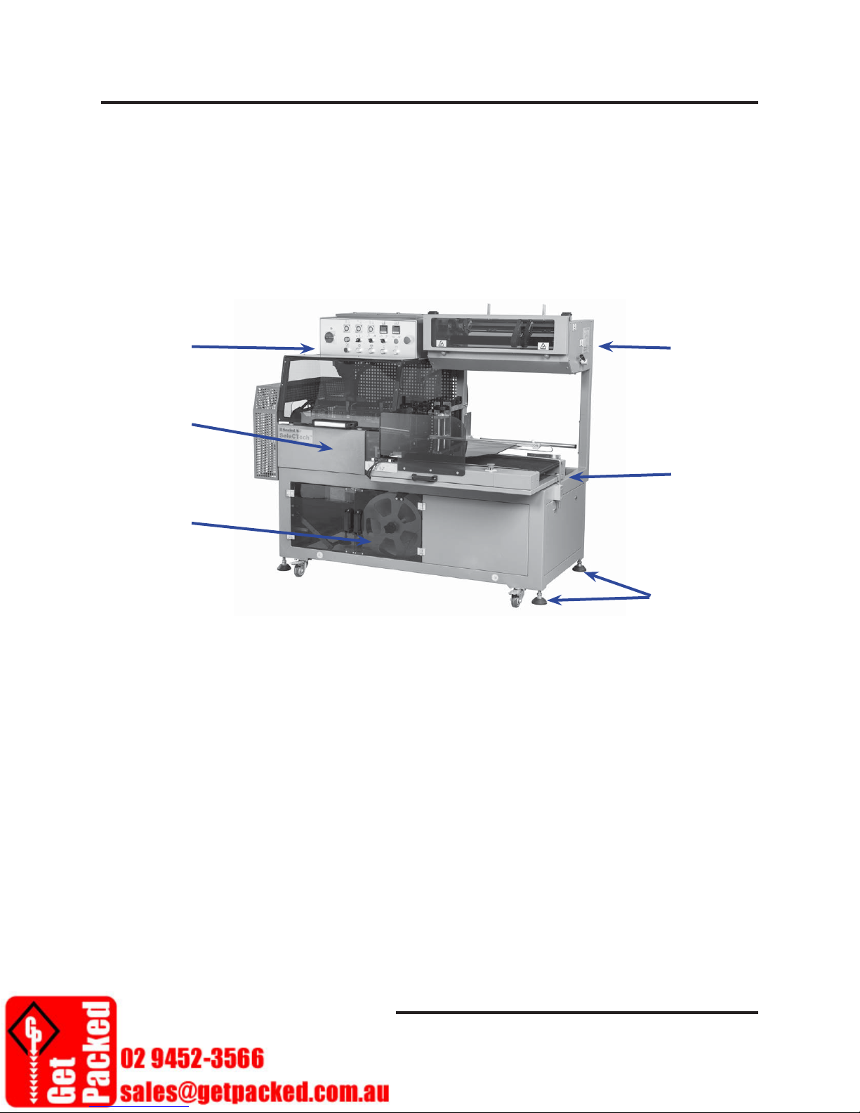
A.2 ILLUSTRATION OF MACHINE PARTS
Use Figure A-2 to identify the major parts of the machine:
1. Control Panel 2. Seal Area 3. Selvage Winder
4. Film Unwind 5. Infeed Conveyor 6. Leveling Feet
1
4
2
5
3
6
Figure A–2 Machine Parts Illustration
A-4
© Sealed Air Corporation (US)
MM-0110; Revision 1-A: 11/01/2013

Section 1. General Information
SLCT-FAL5645 Sealing Machine
SECTION 1. GENERAL INFORMATION
This section details information about safety , transporting, technical support, warranty information,
and equipment certifi cation(s).
IMPORTANT
The Safety section contains information for operating and working on the equipment.
ALL personnel working on or around the equipment are urged to read and understand
the Safety Section and any additional safety information placed throughout this manual.
1.1 SAFETY SECTION .........................................................................1-3
1.1.1 Residual Risks ....................................................................1-3
1.1.2 Pictogram Label Warning Defi nitions .............................1-3
1.1.2.1 General Hazard Pictogram ............................... 1-4
1.1.2.2 Electrical Hazard Pictogram ............................1-4
1.1.2.4 Lifting Hazard Pictogram ................................. 1-4
1.1.2.5 Entanglement Hazard Pictogram ..................... 1-4
1.1.2.6 Pinch Point Hazard Pictogram .........................1-5
1.1.2.7 Shear Hazard Pictogram ................................... 1-5
1.1.2.8 Hidden Knife Warning Pictogram ...................1-5
1.1.2.9 Crushing Hazard Pictogram ............................. 1-5
1.1.2.10 Safety Glove Pictogram ................................... 1-6
1.1.2.11 Safety Eye Wear Pictogram .............................1-6
1.1.3 General Warnings ..............................................................1-7
1.1.4 Energy Isolation .................................................................1-7
1.2 MACHINE TRANSPORT & CRATING ......................................1-11
1.2.1 Uncrating the Machine ......................................................1-11
1.3 TECHNICAL AND CUSTOMER SERVICE SUPPORT ............1-12
1.3.1 Technical Service Support .................................................1-12
1.3.2 Ordering Spare Parts.........................................................1-12
1.3.3 International Customer Service Contacts........................1-12
1.4 CERTIFICATION ...........................................................................1-13
© Sealed Air Corporation (US)
MM-0110; Revision 1-A: 11/01/2013
1-1
Section 1. General Information
SLCT-FAL5645 Sealing Machine
1.1 SAFETY SECTION
DO NOT place this packaging system into operation or undertake maintenance and/or
troubleshooting procedures until all personnel associated with the equipment have become
aware of the warnings and potential hazards outlined in the Safety Section and throughout this
document. It is further advised that the user of this equipment follow the manufacturer’s Safety
statements, cautions, warnings, and energy isolation recommendations while taking the extra
precaution of performing their own safety inspection on the equipment before putting it into
operation or servicing it.
1.1.1 Residual Risks
Although extensive precautions have been taken in the design and manufacture of this packaging
system, all risk of potential hazards cannot be removed and operation of this equipment involves
certain residual risks. To minimize exposure to any residual risks associated with operating or
servicing the machine, ensure that all employees read and understand the safety policies and
instructions for working on and around this machine.
CAUTION
If in doubt about a hazard associated with this machine, contact a
Sealed Air Account Representative prior to operating or working on the
machinery.
WARNING
It is the employer’s responsibility to ensure that:
• Personnel are properly trained
• Personnel follow proper safety procedures.
Under no circumstance should this machine be run with:
• Any of its guards removed
• Any non-functioning safety devices.
1.1.2 Pictogram Label Warning Defi nitions
This paragraph defi nes the meaning of each of the pictograms used on the equipment and in the
machine warnings and cautions outlined in the Safety Section and throughout this manual.
© Sealed Air Corporation (US)
MM-0110; Revision 1-A: 11/01/2013
1-3
Section 1. General Information
SLCT-FAL5645 Sealing Machine
1.1.2.1 General Hazard Pictogram
This symbol is used to signify the presence of a hazard to personnel working
on or around the equipment.
Use caution when following instructions and/or when working around
machine parts labeled with this symbol. Refer to the contents of this manual
for specifi c hazards and concerns.
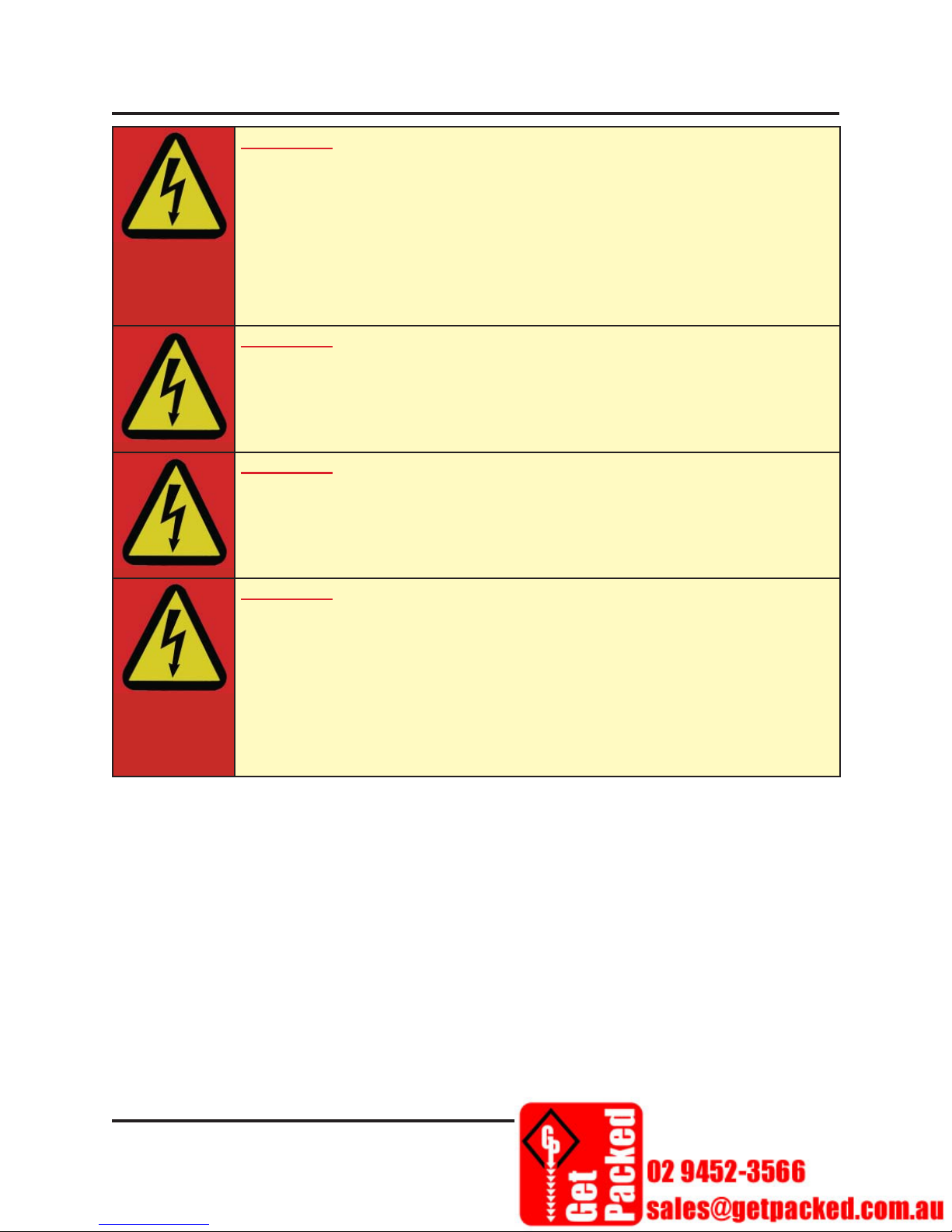
1.1.2.2 Electrical Hazard Pictogram
This symbol is used to signify the presence of an electrical hazard to personnel
working on or around the equipment.
Turn off and lock out system power before servicing equipment or when
following instructions labeled with this symbol.
1.1.2.3 Heat Warning Pictogram
These symbols are used to signify the presence of a thermal hazard to personnel
working on or around the equipment.
Do not remove any protective guards and keep extremities clear of parts
labeled with this symbol. Allow the system to cool completely and turn off and
lock out system power and air before servicing equipment when this safety
label is present or when following instructions labeled with this symbol.
1.1.2.4 Lifting Hazard Pictogram
This symbol is used to signify the presence of a lifting hazard. Personal
injury hazard may occur if an object is lifted without the proper technique or
assistance.
Use assistance and/or proper technique when moving or lifting objects
labeled with this symbol or when following instructions labeled with this
symbol.
1.1.2.5 Entanglement Hazard Pictogram
1-4
© Sealed Air Corporation (US)
MM-0110; Revision 1-A: 011/01/2013
Section 1. General Information
SLCT-FAL5645 Sealing Machine
This symbol is used to signify the presence of moving parts that may present an Entanglement
hazard to personnel working on or around the equipment.
Moving parts can crush and cut. Do not remove protective guards and keep extremities clear
of moving parts at all times when this safety label is present. Turn off and lock out system
power before servicing equipment or when following instructions labeled with this symbol.
1.1.2.6 Pinch Point Hazard Pictogram
This symbol is used to signify the presence of moving parts that may present a
pinch point hazard to personnel working on or around the equipment.
Moving parts can crush and cut. Do not remove any protective guards and
keep extremities clear of moving parts at all times when this safety label is
present. Turn off and lock out system power before servicing equipment or
when following instructions labeled with this symbol.
1.1.2.7 Shear Hazard Pictogram
This symbol is used to signify the presence of moving parts that may present a cutting or shear
hazard to personnel working on or around the equipment.
Moving parts can shear and cut. Do not remove any protective guards and
keep extremities clear of moving parts at all times when this safety label is
present. Turn off and lock out system power before servicing equipment or
when following instructions labeled with this symbol.
1.1.2.8 Hidden Knife Warning Pictogram
This symbol is used to signify the presence of a hidden knife that may present
a cutting hazard to personnel working on or around the equipment.
Moving parts can crush and cut. Do not remove any protective guards and
keep extremities clear of moving parts at all times when this safety label is
present. Turn off and lock out system power before servicing equipment or
when following instructions labeled with this symbol.
1.1.2.9 Crushing Hazard Pictogram
This symbol is used to signify the presence of moving parts that may present
crushing hazards to personnel working on or around the equipment.
© Sealed Air Corporation (US)
MM-0110; Revision 1-A: 11/01/2013
1-5
Section 1. General Information
SLCT-FAL5645 Sealing Machine
Moving parts can crush. Do not remove any protective guards and keep extremities clear of
moving parts at all times when this safety label is present. Turn off and lock out system power
before servicing equipment or when following instructions labeled with this symbol.
1.1.2.10 Safety Glove Pictogram
This symbol is used to signify the presence of a possible hand hazard injury as
a result of working on or around the equipment. In conjunction with safe work
practices, Personal Protective Equipment (PPE) is required when this label is
present. Wear the most appropriate type of safety glove for protection against
cuts, scrapes, punctures, and lacerations when this label is present.
Safety glove selection should be based on the gloves performance
characteristics relative to the specifi c task(s) to be performed, conditions
present, duration of use, and the actual and potential hazards identifi ed.
1.1.2.11 Safety Eye Wear Pictogram
This symbol is used to signify the presence of a possible eye injury hazard as
a result of working on or around the equipment. In conjunction with safe work
practices, Personal Protective Equipment (PPE) is required when this label is
present.
Personal protective eye equipment must meet certain design criteria to be
used as safety equipment and must be worn when workers are at risk from
fl ying particles, liquid/caustic/ acid chemicals or vapors, or operations that
may emit light.
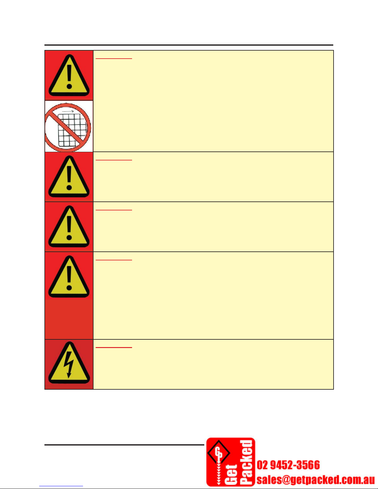
1.1.2.12 Machine Guard Pictogram
This symbol is used to signify the presence of a hazard to personnel working
on or around the equipment when a machine guard(s) is not in place.
Do NOT operate this equipment when guards are missing or open. Serious
injury could occur!
1.1.2.13 Machine Handling Pictogram
This symbol is used to signify the need for a certifi ed forklift operator and
is also used to indicate the correct forklift tine placement when lifting the
machine.
1-6
© Sealed Air Corporation (US)
MM-0110; Revision 1-A: 011/01/2013
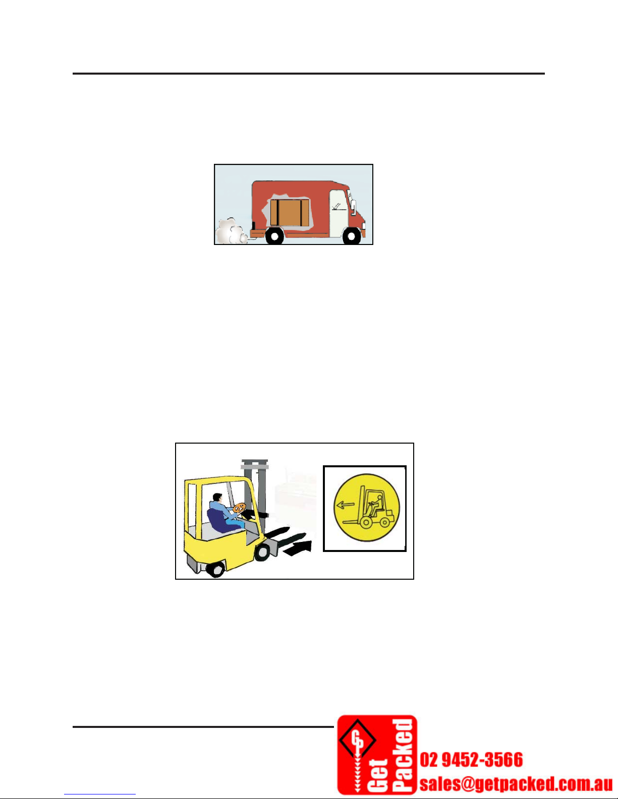
Section 1. General Information
SLCT-FAL5645 Sealing Machine
Do not attempt to move this system from its crate manually; a trained operator should use the
appropriate machine handling equipment to move the machine. Serious injury and/or damage
to the machine could occur!
1.1.3 General Warnings
This paragraph contains general warnings and cautions. In addition to these warnings, other
pertinent warnings and cautions have been placed in relevant places throughout this manual.
WARNING
To minimize potential for personal injuries, ensure that machine operators
and others working on or around the machinery are properly trained in
correct equipment use and safe operating procedures.
WARNING
The use of plastic fi lms in sealing and/or shrinking equipment may result
in the release of hazardous fumes due to the degradation of the fi lm at
high temperatures. Before using any plastic fi lm in this equipment, the
manufacturer or supplier of the fi lm should be contacted for specifi c
information on the potential release of hazardous fumes.
Adequate ventilation should be provided at all times.
WARNING
Keep all extremities, loose clothing, jewelry, and hair away from moving
assemblies and conveyors.
WARNING
Worn or frayed conveyor belts are hazardous and should be replaced
promptly.
© Sealed Air Corporation (US)
MM-0110; Revision 1-A: 11/01/2013
1-7
Section 1. General Information
SLCT-FAL5645 Sealing Machine
WARNING
Never operate this or any moving equipment without all covers and
guards in place. The internal mechanisms of packaging machinery contain
numerous shear, pinch, and in-running nip points capable of causing
severe injury and permanent disfi gurement.
WARNING
Do not place pressurized containers or volatile, fl ammable, or explosive
materials on, into, or through a shrink tunnel. Resulting fi re or explosion
can cause serious injury.
WARNING
Heat sealing jaws and shrink tunnel openings on packaging machines
get very hot. Keep hands away while machinery is in operation and use
caution if the machine has been running recently.
WARNING
Only approved packaging specifi cations and parts should be used with this
system.
Use of other packaging materials and/or parts on the system may
cause unforeseen damage to the machinery and pose safety hazards.
When unauthorized use of parts or materials has occurred, Sealed Air
Corporation reserves the right to refuse services including but not limited
to: maintenance, troubleshooting, supplies, and parts provided by Sealed
Air (US).
WARNING
In order to prevent injury to personnel and/or machinery, do not increase
settings on either electrical or mechanical overload safety devices.
1-8
© Sealed Air Corporation (US)
MM-0110; Revision 1-A: 011/01/2013
Section 1. General Information
SLCT-FAL5645 Sealing Machine
WARNING
Do not make any modifi cations to the programmable logic controller’s
(PLC’s) control program, the electrical circuitry, or the mechanical
assemblies of this machinery. Such modifi cations may introduce hazards
not associated with this machinery.
Sealed Air Corporation cannot be held responsible for malfunctions,
personal injury, or property damage resulting from such unauthorized
modifi cations.
WARNING
Use of extension cords to connect the system to a power supply is
prohibited. The system’s power cord MUST be plugged into a grounded
source.
WARNING
In order to prevent injury to personnel and/or machinery, proper
equipment ground, in accordance with the national, state, and local
electric codes, must be applied to the machine.
WARNING
Do not tamper with, or make any modifi cations to, the programmable
logic controller’s (PLC’s) control program, the electrical circuitry, the
electrical wiring or the mechanical assemblies of this machinery. Such
modifi cations may introduce hazards not associated with this machinery.
Shanklin Corporation cannot be held responsible for malfunctions,
personal injury, or property damage resulting from such unauthorized
modifi cations.
© Sealed Air Corporation (US)
MM-0110; Revision 1-A: 11/01/2013
1-9
Section 1. General Information
SLCT-FAL5645 Sealing Machine
1.1.4 Energy Isolation
The following guidelines are provided to establish a minimum requirement for the disconnection/
isolation of energy sources whenever maintenance or service is performed on equipment and
associated parts. It is further advised that an independent safety study be performed on the
machinery, its installation, and Lockout/Tagout procedures.
CAUTION
Prior to following any maintenance or troubleshooting procedures
outlined in this manual, review these important steps.
1. Read all warnings and cautions listed in this manual’s Safety Section (“1.1 Safety Section”
on page 1-3) and throughout this manual.
2. Shut the equipment down using normal stopping procedure then engage the Emergency Stop
(E-Stop) push button switch by pushing it down.
3. Ensure that all controls are in a neutral or OFF position.
4. The equipment may be isolated from its energy sources by unplugging the main power cord.
5. Then applicable, the equipment may be isolated from pneumatic sources by disconnecting
the main air line.
6. Follow the appropriate Lockout/Tagout recommendations at your facility during shutdown,
maintenance, and restart of the equipment.
1-10
© Sealed Air Corporation (US)
MM-0110; Revision 1-A: 011/01/2013
Section 1. General Information
SLCT-FAL5645 Sealing Machine
1.2 MACHINE TRANSPORT & CRATING
Follow these guidelines for uncrating and recrating the machine.
1.2.1 Uncrating the Machine
1. Use the appropriate machine handling equipment to transport the crated machine.
2. Remove the top and sides of the packing crate and all secondary packing material
surrounding
the machine (shrink wrap, zip ties, cardboard etc).
3. When applicable, smaller components such as zip-tied pneumatic lines and electrical wiring
may be secured on top of the machine’s conveyor. Remove those components and set them
aside for installation.
4. Note that a tool box is shipped with each machine. Locate and remove the tool box along
any associated packing material.
with
5. There are circular forklift icons on each side of the machine. These icons indicate the correct
location for the forklift tines to be placed when moving the machine.
6. Have a qualifi ed operator move the machine off of the shipping pallet to where it will be
stationed.
© Sealed Air Corporation (US)
MM-0110; Revision 1-A: 11/01/2013
1-11

Section 1. General Information
SLCT-FAL5645 Sealing Machine
1.3 TECHNICAL AND CUSTOMER SERVICE SUPPORT
Follow these guidelines to obtain support from Technical Service or to order spare parts from
Customer Service.
1.3.1 Technical Service Support
• Order parts by contacting a Sealed Air Representative or Distributor.
• Have the following information available:
• Company name and contact information.
• Equipment model and serial number.
• A detailed description of the technical issues experienced.
1.3.2 Ordering Spare Parts
• Order parts by contacting a Sealed Air Representative or Distributor.
• Have the following information available:
• Company name and contact information including: shipping address, department (when
applicable), phone number, and shipping address.
• The equipment’s model and serial number.
• Part number information obtained from: an assembly drawing (contained in the back of
this manual) - or - the part data from the nameplate of the specifi c part being replaced.
1.3.3 International Customer Service Contacts
International contact information for replacement parts and technical assistance:
• Sealed Air Africa (Pty) Ltd. +27 11 923 4600 Fax: +27 11 392 1025
• Sealed Air Australia Ltd. +1 800 0808 481 Fax: 1 800 250 650
• Sealed Air Packaging (Shanghai) Co. Ltd. +86 21 3920 2988 Fax: +86 21 3920 2999
• Diversey Gulf FZE +971 4 8819470/31 Fax: +971 4 8819488
• Sealed Air Hong Kong Ltd. +852 2178 7876 Fax: +852 2407 3385
• Sealed Air (India) Pte. Ltd. +91 80 4050 7333 Fax: +91 80 4117 1301
• Sealed Air HK Ltd.-Indonesia Rep +62 21 5793 8858 Fax: +62 21 5793 8859
• Sealed Air (Israel) Ltd. +972 2 5337438 Fax: +972 2 5337439
• Sealed Air (Japan) Ltd. +81 3 5644 1110 Fax: +81 3 5644 1160
• Diversey Eastern & Central Africa Ltd. (Kenya) +254 703 040 247 Fax: +254 703 040 888
• Sealed Air (Korea) Ltd. +82 31 763 1716 Fax: +82 31 763 4744
• Sealed Air (Malaysia) Sdn Bhd +60 3 5569 6363 Fax: +60 3 5569 2682
• Diversey Maroc s.a. (Morocco) +212 522 756 506 Fax: +212 522 756 572/73
• Sealed Air New Zealand +64 9 813 9800 Fax: +64 9 813 9801
• Diversey West Africa Limited (Nigeria) +234 1 825 5511 Fax: +234 813 086 5000-6
1-12
© Sealed Air Corporation (US)
MM-0110; Revision 1-A: 011/01/2013

Section 1. General Information
SLCT-FAL5645 Sealing Machine
• Sealed Air Philippines, Inc. +63 2 845 9400 Fax: +63 2 2811 6679
• Diversey KSA-Arabian Modern Company (Saudi Arabia) +966 3 847 6986-7 Fax: 966 3 847 6989
• Sealed Air (Singapore) Pte. Ltd. +65 6861 1828 Fax: +65 6861 5221
• Sealed Air (Taiwan) Ltd. +886 3 324 2988 Fax: +886 3 324 3088
• Sealed Air (Thailand) Ltd. +66 2 834 6800 Fax: +66 2 834 6888
• Diversey Kimya Sanayi ve Ticaret A.S. (Turkey) +90 216 578 6400 Fax: +90 216 578 6401
• Sealed Air (Singapore) Pte. Ltd.-Vietnam Rep Offi ce +84 8 6292 4251 Fax: +84 8 6296 2606
• Czech Republic +420 224 315 863
• France, Osny +33 (0)3 86 92 04 58
• Germany, Alsfeld +49 (0)6631 96680
• Greece, Shimatari Viotias +30 22620 32551
• Hungary, Újhartyán +36 (06)29 573 300
• Italy, Bellusco +39 039 6835 1
• The Netherlands, Nijmegen +31 (0)24 3710111
• Poland, Ozarów Mazowiecki +48 (0)22 7217 530
• South Africa, Spartan +27 (0)11 923 4600
• Spain, Abrera +34 93 773 8325
• Sweden, Aneby +46 (0)380 47100
• UK, Kettering +44 (0)1536 315700
•
1.3.4 Regulatory Compliance
The SeleCTech SLCT-FAL5645 sealing machine meets essential health and safety requirements
and is in conformity with the relevant EC Directives.
.
© Sealed Air Corporation (US)
MM-0110; Revision 1-A: 11/01/2013
1-13

Section 2. General Information
SLCT-FAL5645 Sealing Machine
SECTION 2. INSTALLATION
This section details information about installing and adjusting the sealing machine.
The machine has already been careully checked and tuned Before leaving the factory. Only
trained operators are allowed to make the adjustments necessary in order to pack products of
different dimensions.
2.1 SELECT THE MACHINE INSTALLATION LOCATION ........ 2-3
2.2 ADJUSTING THE HEIGHT OF THE SEALING MACHINE ... 2-3
2.3 LOADING THE SHRINK FILM ...................................................2-4
2.3.1 Film Loading. .....................................................................2-4
2.3.2 Adjusting Film ....................................................................2-4
2.3.3 Front Conveyor Belt Adjustment ....................................2-5
2.3.4.1 Film Sealing ........................................................ 2-6
2.4 SEALING SAFETY SENSOR ........................................................2-7
2.5 REMOVING THE WASTED SIDE FILM .................................... 2-8
© Sealed Air Corporation (US)
MM-0110; Revision 1-A: 11/01/2013
2-1
Section 2. General Information
SLCT-FAL5645 Sealing Machine
2.1 SELECT THE MACHINE INSTALLATION LOCATION
The sealing machine should placed well-lit and dry place. It should be positioned away from
dusty, fl ammable, explosive and corrosive areas.
Placing the sealing machine too close to the ventilation system may cause unstable fi lm delivery.
.
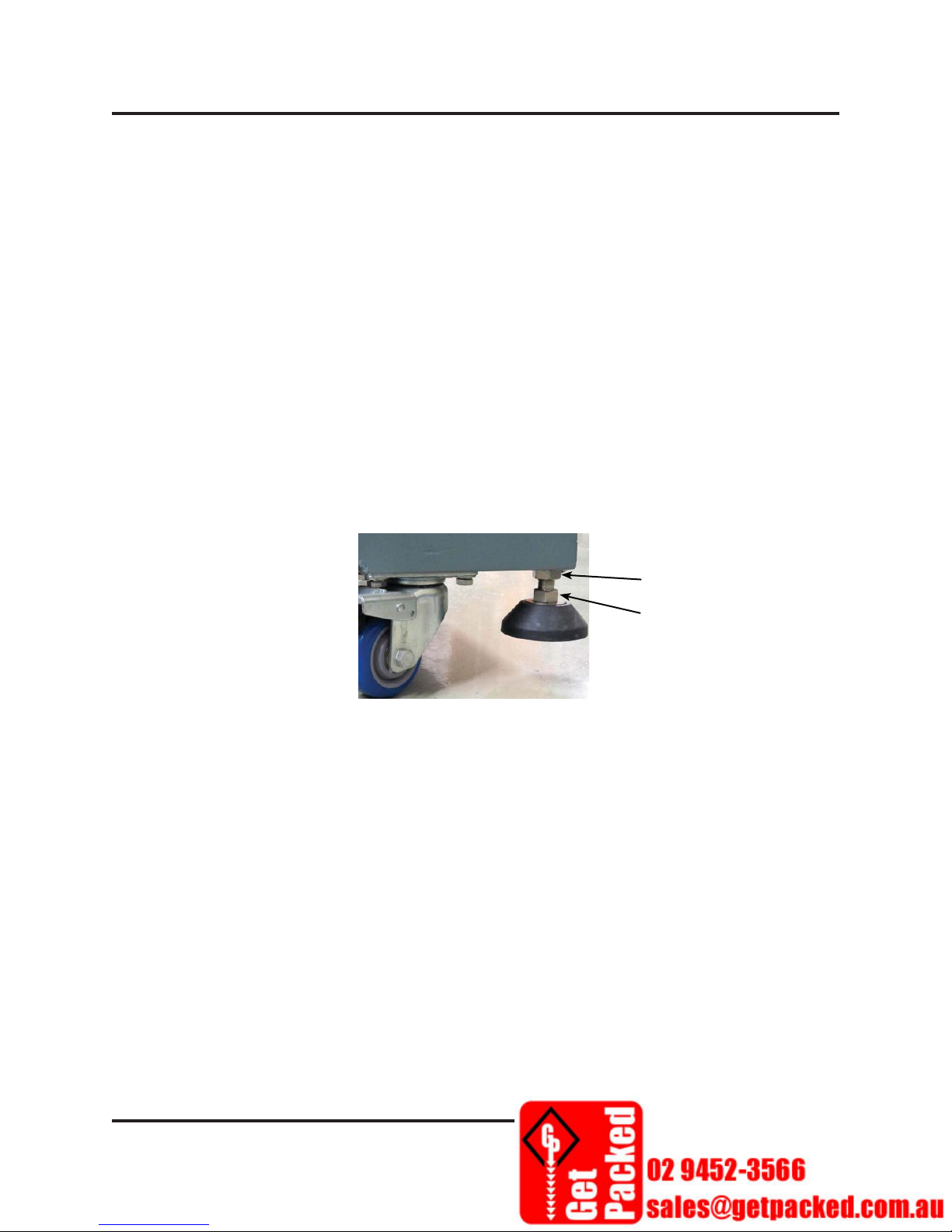
2.2 LEVELING THE SEALING MACHINE
Refer to Figure 2-1 for the following system leveling/height adjustment procedure. The steps
apply to all four (4) feet on the base of the system.
1. Use a spanner to loosen the lock nut (1) at the sealing machine base.
2. Use a spanner to
is at the required height, tighten the lock nut
turn the nut on the height adjustment screw (2). When the sealing machine
Figure 2–1 Sealing Machine Leveling/Height Adjustment
(1) up to the base of the machine.
1
2
© Sealed Air Corporation (US)
MM-0110; Revision 1-A: 11/01/2013
2-3
Section 2. General Information
SLCT-FAL5645 Sealing Machine
2.1 LOADING THE SHRINK FILM
When the fi lm is properly loaded the motorized fi lm unwind assembly provides fi lm as required
by the packing process.
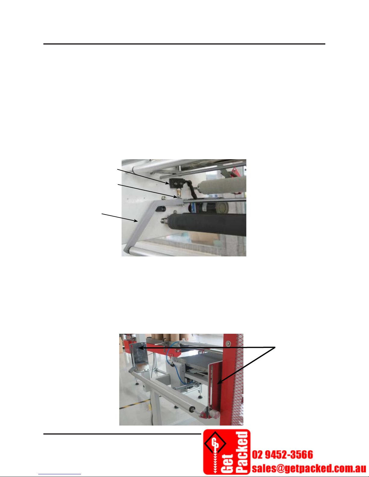
2.1.1 Film Loading Micro-switch and Contact Wheel
The micro switch located above the left side of the dancer assembly controls the operation of the
fi lm delivery motor. When the actuator wheel on the side of the arm touches the micro-switch,
the fi lm delivery motor starts running. When the fi lm pressure relaxes, the arm lowers, the
actuator wheel no longer touches the micro-switch, and the motor stops. The actuator should just
slightly touch the micro-switch.
Micro switch
Actuator Wheel
Dancer Bar Arm
Figure 2–2 Film Delivery Assembly
2.1.2 Film Feed Roller Height Adjustment
1. Loosen the locking nuts on each end of the fi lm feed roller,
2. Adjust the fi lm roller set up or down as required, based on
the height of sealing area.
2-4
Roller Locks
© Sealed Air Corporation (US)
MM-0110; Revision 1-A: 11/01/2013

Section 2. General Information
SLCT-FAL5645 Sealing Machine
Figure 2–3 Roller Locks
2. The proper height adjustment will be based on actual operating conditions. Irregular, jumping
motion of the fi lm delivery may indicate the need to adjust the delivery angle.
2.1.3 Conveyor Belt Adjustment
The conveyor belt tension is set at the factory, but may loosen over time. If the belt becomes
loose refer to Figure 2-4 as you use the belt tension adjustment procedure described here:
1. Loosen the Lock Nuts (1) and (2)
2. Turn the adjusting nut (3) clockwise to push the roller forward to increase the belt tension.
3. It is important to make the same adjustment on the other side of the conveyor.
(3)
(2)
(1)
Figure 2–4 Belt Tension Adjustment
© Sealed Air Corporation (US)
MM-0110; Revision 1-A: 11/01/2013
2-5

Section 2. General Information
SLCT-FAL5645 Sealing Machine
2.1.3.1 Film Sealing
Before operating the system, check to ensure that the seal wires and upper jaws are clean.
Any residual fi lm caught on or between the wires and the ceramic beads can cause poor seals.
The lower beds should also be kept in good condition. Over time the Tefl on tapes may show
impressions from the wire and some discoloration, this is normal, but burned or blackened tapes
should be replaced. This could be an indication of too much pressure or uneven pressure.
Contact between the sealing blade and the sealing base can be checked as follows:
1. Put a white paper between the sealing blade and base.
2. Manually operate the sealing and cutting process once to see if the force of the sealing and
cutting action is even on the white paper.
3. If it is uneven, loosen the lock nuts and turn the adjusting screws. (Caution this adjustment
must be made with the machine power off and the assembly cooled down.)
4. Tighten the locking nut
Adjustment
Screws
Adjustment
Screws
Figure 2–5 Sealing Assembly
2-6
© Sealed Air Corporation (US)
MM-0110; Revision 1-A: 11/01/2013

Section 2. General Information
SLCT-FAL5645 Sealing Machine
2.2 SEALING JAW SAFETY
To prevent injury, product crushing or machine damage the jaw is equipped with several safeties
that will stop the machine operation if a product or other object is inside the sealing area when
the sealing blade lowers.
The operation of the jaw safety circuit should be verifi ed at least once per day. The jaw safety
circuit is designed to reopen the jaws immediately whenever the jaws contact an object upon
closing. The test requires attempting to make a seal with a rubber test object between the jaws.
When functioning properly, the jaw safety circuit will force the machine into an Emergency Stop
state upon contact with the test object.
2.2.1 Jaw safety Verifi cation Test
1. Ensure that all guards are in place. All doors and hoods must be closed.
2. Connect the compressed air supply for the machine.
3. Power up the machine.
4. Press the E-STOP button.
5. Test object should be resilient. Preferably a spare piece seal bed material (3/8” thick silicone
rubber). Place the test object on the conveyor belt between the seal jaws.
6. Release the E-STOP button by twisting clockwise.
7. Put the machine into a READY state by pressing the READY button (Blue).
8. Perform the test by pressing the manual seal button. The button must be held down until the
jaws close completely.
• PASS INDICATION: Jaws close and then immediately reopen; the READY light Flashes.
• FAIL INDICATION: Jaws do not reopen immediately and/or READY light remains on.
9. Repeat Steps 4-8 several times with the rubber object at different points along the entire length
of each seal jaw to ensure the integrity of the Jaw Safety Circuit.
© Sealed Air Corporation (US)
MM-0110; Revision 1-A: 11/01/2013
2-7

Section 2. General Information
SLCT-FAL5645 Sealing Machine
Adjust Actuator
Figure 2–6 Safety Actuator
If the jaw safety does not work properly: Loosen the top actuator screw and raise or lower it
to allow the sensor to detect the packing product quickly. The distance between the two touch
screws should not be too long, otherwise, the sealing blade will alarm and stop operation before
completing the sealing and cutting action.
2.3 REMOVING THE WASTE FILM (SELVAGE)
The fi lm trimmed from the side during the packing process is called selvage. Selvage is collected
on a wheel located in a compartment at the front of the machine. Refer to Figure 2-7 and follow
the next procedure to remove the waste fi lm that has accumulated on the selvage winder.
1. Open the door to access the selvage winder.
2. Loosen the wheel lock on the front of the wheel, and remove the guide plate.
3. Remove the waste fi lm,
4. Replace the guide plate and tighten the locking cap.
5. Run out some fi lm and re feed the selvage to the wheel. If the wheel slips during the
receiving process, tighten the locking nut a little bit to increase the friction of the selvage
receiving reel
Wheel Lock
Selvage Winder
Location
Guide Plate
2-8
Figure 2–7 Selvage Winder
© Sealed Air Corporation (US)
MM-0110; Revision 1-A: 11/01/2013

Section 2. General Information
SLCT-FAL5645 Sealing Machine
© Sealed Air Corporation (US)
MM-0110; Revision 1-A: 11/01/2013
2-9

Section 3. Operation
SLCT-FAL5645 Sealing Machine
SECTION 3. OPERATION
This section details information about installing and adjusting the sealing machine.
Before machine delivery, the machine has already been precisely checked and tuned. “Do
not” change the setting unless it is necessary. However, trained operators are allowed to make
adjustments to some of the necessary settings in order to pack different dimensions of the
packing products.
3.1 CONTROL PANEL .........................................................................3-3
3.2 NAMEPLATE ..................................................................................3-4
3.3 INSTALLING THE SHRINK FILM .............................................3-5
3.4 FUNCTIONS ....................................................................................3-10
3.5 OPERATION .................................................................................... 3-12
© Sealed Air Corporation (US)
MM-0110; Revision 1-A: 11/01/2013
3-1

3.1 CONTROL PANEL
1234567
Section 3. Operation
SLCT-FAL5645 Sealing Machine
891011121314151617
Figure 3–1 Control Panel
Call
out
1 Main Circuit Breaker Switch turns ON/OFF the power input
2 Resets the machine (Flashes Blue light until pushed)
3 Starts the conveyor
4 Stops the conveyor
5 Cycles the sealing/cutting process once
6 Manually runs the fi lm feed motor until the button is released
7 Emergency stops the machine. Must be released to restart machine.
8 Not Used
9 Sets the temperature of the Front sealing blade
10 Selects Horizontal Sensor mode for rectangular or square products
11 Sets the temperature of the Side sealing blade
12 Sensor mode to control the packing process
13 Sets the conveyor run time for length of fi lm at the back of the product
14 Switches ON/OFF the heater for the sealing blades
15 Sets the sealing/cutting dwell time
16 Sets the conveyor run time for fi lm length at the front of the product
17 Power ON light (Green)
Description
© Sealed Air Corporation (US)
MM-0110; Revision 1-A: 11/01/2013
3-3

Section 3. Operation
SLCT-FAL5645 Sealing Machine
3.2 NAMEPLATE
Figure 3–2 Nameplate
Call out Description Call out Description
1
2
3
4
5
6
MODEL Number
Vn (Rated voltage)
FLA (Rated current)
S/N (Serial number)
Date of Manufacture
Short-circuit current (SCCR)
7
8
9
10
11
HZ (frequency)
SCHEMATIC
LARGEST LOAD (Amps)
WEIGHT
MAXPSI
3-4
© Sealed Air Corporation (US)
MM-0110; Revision 1-A: 11/01/2013

Section 3. Operation
SLCT-FAL5645 Sealing Machine
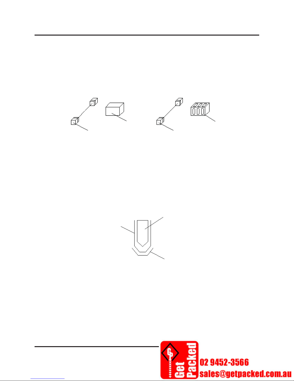
3.3 INSTALLING THE SHRINK FILM
The dimensions of the packing product are width (W), the height (H), and the length (L) as
shown in Figure 3–33.
Figure 3–3 Packing Product Dimensions
1. Start the conveyor.
2. Check that the belt is tracking at the center of the bed. If not, follow the adjustment procedure
on Page 2-5 to adjust the belt.
3. Select the appropriate shrink fi lm:
Width of shrink fi lm = W (Product Width) + H (Product Height) + 5” ~ 7” (depends on the
height of the packing product).
4. Adjust the infeed conveyor Height (see Figure 3–4): Rotate the conveyor adjusting wheel to
adjust the height of the triangular plate. The correct position is about 1/2 H (Product Height)
+ 5~10mm.
5. Adjust of the infeed conveyor relative to the product guide (Figure 3-4)by placing a product
on the belt and then squeezing the handle on the front of conveyor unit. This will enable
movement of the conveyor unit to the appropriate width which is W (Product Width) plus
one-third of the product height.
© Sealed Air Corporation (US)
MM-0110; Revision 1-A: 11/01/2013
3-5

Section 3. Operation
SLCT-FAL5645 Sealing Machine
Product Guide
is mounted
to side of the
machine
Inverting Heads
above and
below infeed
conveyor
Figure 3–4 View FAL 5645 from the Infeed end
6. Put the shrink fi lm onto the Film Unwind rollers (see Figure 3–5).
a. Loosen the locking nut of the left side fi lm positioning rod (1) and adjust the fi lm
location. Tighten the locking nut after adjustment
b. Loosen the locking nut of the right side fi lm positioning rod (2) and adjust the rod to
width of the shrink fi lm + 5 mm. Tighten the locking nut after adjustment.
c. The open side of the shrink fi lm must face to the fi lm positioning rod (2).
3-6
© Sealed Air Corporation (US)
MM-0110; Revision 1-A: 11/01/2013

Section 3. Operation
SLCT-FAL5645 Sealing Machine
Folded Film Open Side
Film Positioning
Rod 1
Film Positioning
Rod 2
Web Separator
Inverting Heads
above and
below infeed
conveyor
7. Switch the Temperature Controllers ON and adjust the temperature of the front and side
sealing wires for the type of fi lm being used.
Film Type Required Temperature Film Type Required Temperature
PE Film 220°C~240°C POF Film 200°C~220°C
© Sealed Air Corporation (US)
MM-0110; Revision 1-A: 11/01/2013
Figure 3–5 Film Unwind Assembly
3-7
Section 3. Operation
SLCT-FAL5645 Sealing Machine
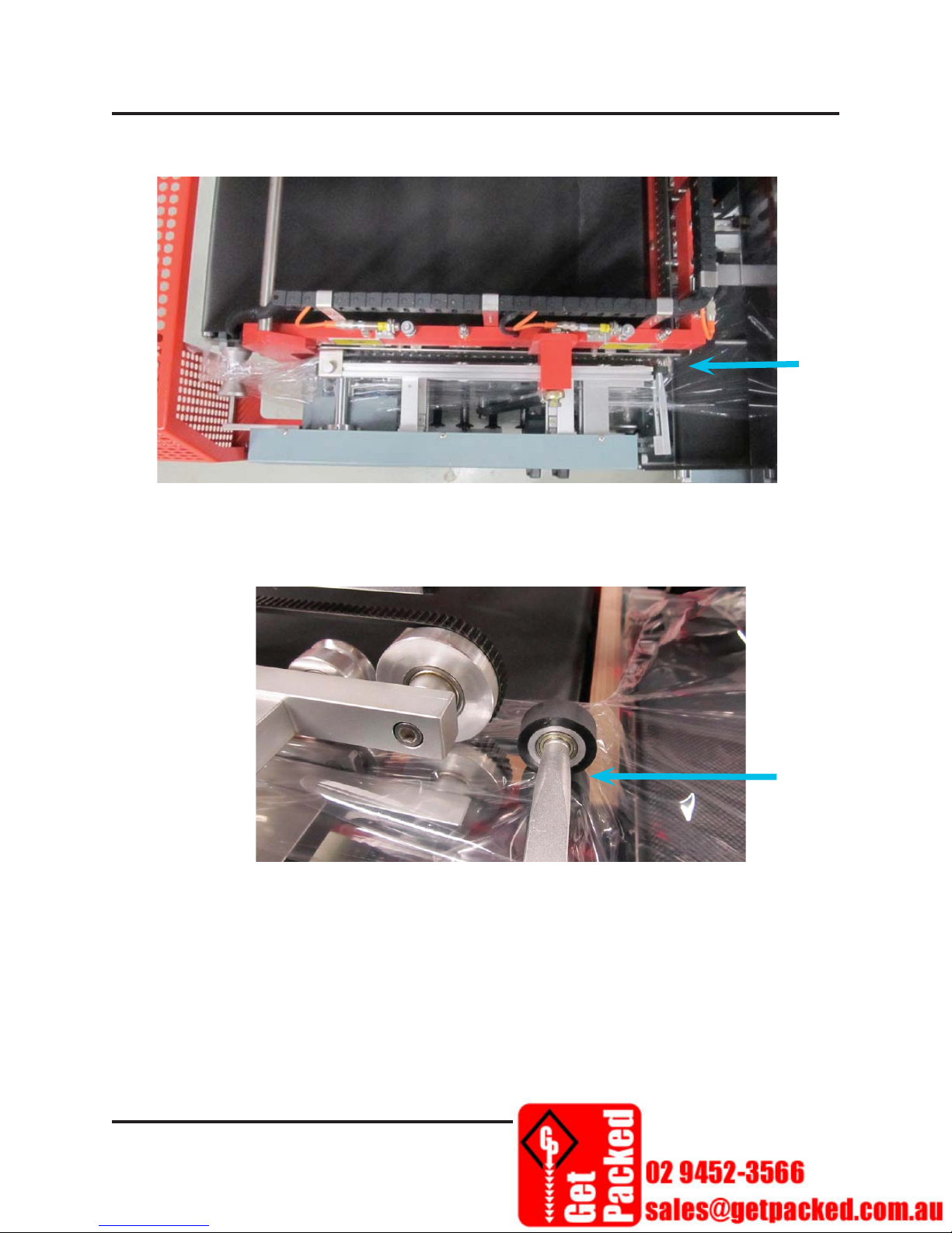
8. Loading the Shrink Film (see Figure 3–6 and Figure 3–7).
Feed Film
here
Figure 3–6 Overhead View of Film Puller Assembly
Start Film Feed
here
Figure 3–7 Film Assembly
9. After the sealer reaches the set temperature, press the Manual operation button once, the
Sealer will move once, and jaws will remain open.
10. Turn on the conveyor, and place a product on the infeed conveyor. The machine should
advance fi lm and cycle the sealer once. The wrapped product will exit the machine.
11. Continue to run the fi lm feed, while pulling the selvage end of the fi lm until the selvage can
be wound 2~3 times on the receiving reel (Figure
process automatically.
3-8
3–8). Now the machine can run the packing
© Sealed Air Corporation (US)
MM-0110; Revision 1-A: 11/01/2013

Selvage Path
Illustration
12. Switch the conveyor ON, put the packing product on the conveyor and make sure that your
hands are completely away from the conveyor surface.
Section 3. Operation
SLCT-FAL5645 Sealing Machine
Selvage Reel
Cover Lock
Figure 3–8 Selvage Reel
13. Adjust the sealing and cutting process as necessary. (Figure
3–9).
Film Seal Line
Conveyor Direction
Figure 3–9 Sealing and Cutting Adjustment
14. Adjust of the front extra fi lm length (Length A of Figure 3–9), to the best length
approximately 1/3 H. The adjustment procedure is as follows:
a. When A is too long, shorten the distance between the sensor and the sealing blade by
increasing the conveyor time setting on switch #16 in Figure 3-1.
b. If A is too short, adjust the conveying time for the extra fi lm length at the front of the
product, increasing the conveying time to increase the extra fi lm length at the front of the
box.
© Sealed Air Corporation (US)
MM-0110; Revision 1-A: 11/01/2013
3-9

Section 3. Operation
SLCT-FAL5645 Sealing Machine
Sealing and Cutting
Blade
Sealing and Cutting Base
Packing Product
Optical Sensor
Figure 3–10 Horizontal Sensors
15. The best rear extra fi lm length (B of Figure 3–9), is 1/2 H between the product and the rear
seal. Adjust the
conveyor time setting on switch #13 in Figure 3-1 to increase the fi lm length
at the rear of the package.
16. Different shrink fi lms have different sealing time (Typically 0.3~0.6 seconds). The fi lm
must be sealed and cut completely and steadily without holes. Poor fi lm cutting may be
caused by overheating on the sealing process. Adjusting the sealing dwell time or the sealing
temperature should eliminate this issue.
17. When the sealing and cutting line is good, the adjustment process is fi nished.
3.4 FUNCTIONS
• The machine includes a warning system, and a safety function.
• The sealing and cutting process can operate continuously.
• Simple machine operation can match various sizes of packing products.
• PLC and optical sensor control are applied on this machine.
• Two types of optical sensors (Horizontal type and Vertical type): Horizontal type optical
sensors (as shown in
Figure 3–10) are applied on packing square or rectangular product.
It includes a wait function. The Vertical optical sensor is mostly used for packing thinner
products, but there is no wait function on this sensor.
• According the characteristics of the product, there are two types of the sensor mode selection:
Standard type and point-to-point compensation type (as shown on
3-10
Figure 3–11):
© Sealed Air Corporation (US)
MM-0110; Revision 1-A: 11/01/2013
Section 3. Operation
SLCT-FAL5645 Sealing Machine
• When the products are in rectangular or square shape, Standard sensor mode should be
applied.
• If the packing products are an irregular shape or transparent, then the Point-to-point
Compensation sensor mode should be applied and the Conveying Time switch adjusted to
control the fi lm length.
Packing Product
Optical Sensor
Packing Product
Optical Sensor
Figure 3–11 Packing Product Sensor Mode
18. The sealing blade of this machine can be used on the POF and PE Shrink Film. When using
on the PE Shrink Film, the sealing blade must be covered by heat-resisted adhesive tape to
prevent the blade from directly contacting the PE fi lm.
Sealing Blade
Protective Plate
Heat-resisted Adhesive Tape
© Sealed Air Corporation (US)
MM-0110; Revision 1-A: 11/01/2013
3-11

Section 3. Operation
SLCT-FAL5645 Sealing Machine
3.5 OPERATION
3.5.1 Typical Operation
The machine employs an infeed conveyor and a discharge conveyor mounted at the same
elevation to convey product through the machine. The upper seal jaws and lower seal beds
both pivot such that they meet at the center line of the package when a seal is being made. The
infeed conveyor carries product through the fi lm inverting head where it is surrounded with
plastic shrink fi lm supplied by a powered fi lm unwind assembly. When the product reaches
the proper position in the sealing area, the conveyors stop and the Sealer cycles, making a seal
and cutting fi lm on two edges of the package. After sealing is completed, the seal jaws open
and the discharge conveyor carries the product out of the machine while the infeed conveyor
simultaneously delivers the next product to the sealing area.
3.5.2 Starting the Machine
1. Switch ON the Main Circuit Breaker to power the machine.
2. Turn ON or attach the air supply.
3. Switch ON the heater controls and allow the sealers to reach operating temperature.
4. Turn ON the conveyor.
5. Put a product onto the conveyor and the machine will pack the product automatically.
6. If abnormal machine operation occurs, then press the Emergency Stop switch to immediately
stop the sealing machine.
7. The blue Reset Button will fl ash until abnormal operation has been corrected and the E-Stop
has been released by twisting it clockwise.
3.5.3 Shutting Down the Machine
1. Turn off the heater control switches and allow the sealer unit to cool down.
2. Next, switch off the power supply.
3. If it is necessary to shut-down the air supply, be aware that it will cause the sudden
downward movement of the sealing/cutting jaws when the air is disconnected.
3-12
© Sealed Air Corporation (US)
MM-0110; Revision 1-A: 11/01/2013

Section 4. Maintenance & Troubleshooting
SLCT-FAL5645 Sealing Machine
SECTION 4. MAINTENANCE & TROUBLESHOOTING
This section details information about maintaining and troubleshooting the sealing machine.
4.1 MACHINE MAINTENANCE ........................................................ 4-3
4.2 TROUBLESHOOTING ..................................................................7
© Sealed Air Corporation (US)
MM-0110; Revision 1-A: 11/01/2013
4-1
Section 4. Maintenance & Troubleshooting
SLCT-FAL5645 Sealing Machine
4.1 MACHINE MAINTENANCE
Regular maintenance is the best way to ensure smooth operation and optimal machine life. The
following are the general machine maintenance guidelines. Only trained machine operators and
service technicians are authorized to perform maintenance on this machine.
IMPORTANT
Review and follow the Safety Guidelines in Chapter 1 of this Manual and site-specifi c
Lock Out/Tag Out Procedures when necessary.
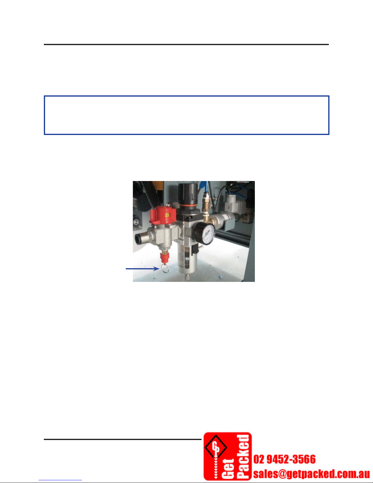
• Maintenance of Pneumatic Regulator Unit:
When the water level reaches 2/3 of the height of the water fi lter tank, the tank water must be
drained out. To drain water, pull down the ring on the water drain plug.
Water Drain
Figure 4–1 Pneumatic Regulator Unit
• Clean the Workstation before the start operation each day.
a. Use only compressed air to clean the work area.
b. Only use soft wood to clear the fi lm reside on the sealing blade. Do not use metal or other
abrasive materials.
• Monthly Maintenance of the Selvage Receiving Wheel
a. Remove the locking nut, take out the spring and the receiving wheel.
b. Lubricate the contact surfaces of the receiving wheel and the center rod for smooth wheel
rotation
c. Replace the spring and receiving wheel and tighten the locking nut.
© Sealed Air Corporation (US)
MM-0110; Revision 1-A: 11/01/2013
4-3

Section 4. Maintenance & Troubleshooting
SLCT-FAL5645 Sealing Machine
• Chain and wheel maintenance (every 3 months):
a. Take off the cover and put the grease oil onto the gap between the chain and the wheel.
b. Put the cover back on.
c. Bearing and bearing holder maintenance: Service once every 3 months, using the
hydraulic pressure oil to lubricate the bearings and its parts.
• Check Tension and Tracking of the Conveyor Belt.
a. After a period of operation, the conveyor belt may loosen. To adjust the belt tension,
loosen the two lock nuts on each tension adjustment screw. Turn the screw clockwise to
tighten.
b. If the conveyer belt is not tracking down the middle of the bed, slightly turn the adjusting
screw on the side where the belt is close, in a clockwise direction. Allow the belt to run
for a few minutes to see if it moves to the center. It may take several small adjustments
• If the Tefl on detaches from the sealing blade and fi lms easily stick onto the blade, re-stall the
new T efl on or change the new sealing blade.
• Check the Tefl on tape covering the silicon bar. If the tape is damage, replace it.
• Change the heater tube if the heater cannot heat-up the temperature:
a. Before replacement, check the watt and voltage of the heater, switch off the power and
wait the heater to cool-down.
b. Disconnect the heater wire at the electric and control box.
c. Loosen the locking screw of the heater tube and replace the heater tube.
d. Make sure that all screws are tightened, then re-connect the heater wire at electric and
control box.
4-4
© Sealed Air Corporation (US)
MM-0110; Revision 1-A: 11/01/2013

Section 4. Maintenance & Troubleshooting
SLCT-FAL5645 Sealing Machine
• Change the silicon bar and the heat-resistant adhesive tape:
Lower Sealing Frame
Heat-resistant Adhesive Tape
Silicon Bar
Sealing Base
Sealing Blade Base
Figure 4–2 Silicon Bar and the Heat-Resistant Adhesive Tape
a. Switch off the power and allow the sealing bars to cool-down Remove the old heat-
resistant adhesive tape.
b. Replace the silicon bar. Make sure the bar surface is fl at. If necessary, trim away any
excess silicon bar.
c. Apply new heat-resistant tape and make sure the tape surface is fl at.
• Replacement and adjustment of the sealing blades:
a. Remove the sealing blade shields.
Sealing Blade
Protective Shields
b. Remove the faulty sealing blade assembly
© Sealed Air Corporation (US)
MM-0110; Revision 1-A: 11/01/2013
Figure 4–3 Sealing Blade Shields
5

Section 4. Maintenance & Troubleshooting
SLCT-FAL5645 Sealing Machine
c. Replace the sealing blade and make sure the blade is between two guiding plates.
Figure 4–4 Front Sealing Blade without Shields
Sealing Blade
Figure 4–5 Sealing Blade.
Figure 4–6 Front blade alignment
d. Align the new front sealing blade by using the side sealing blade as a guide.
e. Tighten the front blade set after the aligning the blade.
f. Install the protective shields.
6
© Sealed Air Corporation (US)
MM-0110; Revision 1-A: 11/01/2013

Section 4. Maintenance & Troubleshooting
SLCT-FAL5645 Sealing Machine
4.2 TROUBLESHOOTING
Item Problem Possible Causes Recommended Action
Power not connected Connect the power cord
No power to the
1
machine
Main Circuit Breaker is OFF Turn “ON” the CB
ON/OFF switch is damaged Change the switch
Fuse is broken Change the fuse
E-Stop is pressed Release the E-Stop
Power connected but
2
the machine does not
work
PLC does not work Check the power
connection to PLC
PLC is not functioning Change the PLC
Door or Cover interlock open Check covers and doors
The heater switch is ”OFF” Switch “ON” the heater
Temperature is set too low Adjust the temperature
Heater switch is not
Change the heater switch
functioning
3 Heater does not work
The temperature controller is
not functioning
Change the temperature
controller
Relay (SSR) is not functioning Change the SSR
The heater tube is not
Change the heater tube
functioning
Relay (SSR) is not functioning Change the relay (SSR)
Temperature is out of
4
control
The fi lm conveying
5
motor does not run
The temperature detector is
loose out or not functioning
Temperature controller is not
functioning
Film conveying switch is not
functioning
The fi lm conveying relay is not
functioning
The fi lm conveying motor is
overloaded or overheated
The fi lm conveying motor is
not functioning
Tight back the detector or
change the detector
Change the temperature
controller
Change the fi lm conveying
switch
Change the fi lm conveying
relay
Remove the cause and
restart the system
Change the fi lm conveying
motor
© Sealed Air Corporation (US)
MM-0110; Revision 1-A: 11/01/2013
7

Section 4. Maintenance & Troubleshooting
SLCT-FAL5645 Sealing Machine
Item Problem Possible Causes Recommended Action
The connecting point [1001] of
PLC is not functioning
Change the connecting
point [1001] and the
program of PLC or Change
the PLC
Front conveyor motor
6
does not work
The relay of front conveyor
motor is not functioning
The front conveyor motor is
overloaded or overheated
The front conveyor motor is
not functioning
The connecting point [1002] of
PLC is not functioning
Change the relay of front
conveyor motor
Remove the cause and
restart the system
Change the front conveyor
motor
Change the connecting
point [1002] and the
program of PLC or Change
the PLC
Rear conveyor motor
7
does not work
Relay of rear conveyor motor
is not functioning
The rear conveyor motor is
overloaded or overheated
The rear conveyor motor is not
functioning
The connecting point [1003] of
PLC is not functioning
Replace the relay of rear
conveyor motor
Remove the cause and
restart the system
Replace the rear conveyor
motor
Change the connecting
point [1003] and the
program of PLC or Change
the PLC
The wasted fi lm
8
receiving motor does
not work
The sealing base unit
9
does not work
Relay of the wasted fi lm motor
is not functioning
Manual fi lm conveying switch
is not functioning
The wasted fi lm motor is over
loaded or overheated
The wasted fi lm motor is not
functioning
The connecting point [1004] of
PLC is not functioning
The manual sealing operation
switch is not functioning
Change the relay of the
wasted fi lm motor
Change the manual fi lm
conveying switch
Remove the cause and
restart the system
Change the wasted fi lm
motor
Change the connecting
point [1004] and the
program of PLC or Change
the PLC
Change the manual sealing
operation switch
4-8
© Sealed Air Corporation (US)
MM-0110; Revision 1-A: 11/01/2013

Section 4. Maintenance & Troubleshooting
SLCT-FAL5645 Sealing Machine
Item Problem Possible Causes Recommended Action
10
Warning Buzzer of the
sealing process is “ON”
The micro-switch of the sealing
process is blocked
Product is pressed by the
sealing blade
The machine stop when the
sealing blade presses down and
the buzzer is “ON”
Reposition the micro-
switch
Press the Manual sealing
operation switch to remove
the pressed product
Lower the actuator or
adjust the magnetic spring
switch of the cylinder
forwards to the normal
position
Sealing time is short Increase the sealing time by
0.1 second until the proper
sealing time is achieved
11
Incomplete sealing or
cutting, or the sealing
line is broken
The upper sealing blade and the
sealing base do not completely
contact each other
Tefl on tape is damaged Change the Tefl on tape
The silicon bar of the sealing
Adjust the sealing blade
position
Replace the silicon bar
base is damaged
The protective plates are not
Adjust the protective plates
completely contacted
12
The waste fi lm
conveying does not
stop
Too much fi lm residue is
sticking on the sealing wire
optical sensors are out of
alignment
Optical sensor is not
Clear the fi lm residue and
lower dwell time
Align the optical sensors
until the sensor light is ON
Change the optical sensor
functioning
13 Product pressed by the
side sealing blade
Product does not convey on the
guiding side
Put the product correctly
on the guiding side of the
conveyor
14 Product pressed by the
front sealing blade
The Conveying time of extra
fi lm at the rear is too short
and the product does not
Increase the conveying
time of extra fi lm at the
rear side of the product
completely pass through the
sealing blade unit
The packing product is
transparent or has an irregular
Try to use the point to point
compensation sensor mode
shape
© Sealed Air Corporation (US)
MM-0110; Revision 1-A: 11/01/2013
4-9

Section 4. Maintenance & Troubleshooting
SLCT-FAL5645 Sealing Machine
Item Problem Possible Causes Recommended Action
15 The front conveyor belt
Improper front roller tension Adjust the belt tension
is tracking to either side
during operation
16 Film loading is not
smooth or too tight to
Wrong fi lm unwind setup Reload the fi lm unwind,
see Fig. 4.3
load the fi lm
17 Position change of the
upper or lower fi lm
layer
The parallel fi lm roller set is
not level
Stabilization of the shrink fi lm
Adjust the parallel fi lm
roller set, see Fig. 4.4
Change the fi lm
is not good
18 Cannot remove the
wasted fi lm from the
wasted fi lm receiving
reel or too loose
The spring of the reel is too
tight or too loose
If the wasted fi lm is too
tight, release the screw
outside the spring a little
bit or tight the screw a little
bit if the fi lm is too loose.
4-10
© Sealed Air Corporation (US)
MM-0110; Revision 1-A: 11/01/2013

Section 4. Maintenance & Troubleshooting
SLCT-FAL5645 Sealing Machine
© Sealed Air Corporation (US)
MM-0110; Revision 1-A: 11/01/2013
4-11

Section 5. Reference Documents
SLCT-FAL5645 Sealing Machine
SECTION 5. REFERENCE DOCUMENTS
This section details information about circuit diagrams, mechanical parts lists, and a pneumatic
chart.
5.1 CIRCUIT DIAGRAMS ...................................................................5-3
5.2 MECHANICAL PARTS LIST ........................................................5-5
5.3 PNEUMATIC CHART ....................................................................5-19
© Sealed Air Corporation (US)
MM-0110; Revision 1-A: 11/01/2013
5-1

5.1 CIRCUIT DIAGRAMS
Section 5. Reference Documents
SLCT-FAL5645 Sealing Machine
© Sealed Air Corporation (US)
MM-0110; Revision 1-A: 11/01/2013
5-3

Section 5. Reference Documents
SLCT-FAL5645 Sealing Machine
5-4
© Sealed Air Corporation (US)
MM-0110; Revision 1-A: 11/01/2013

5.2 MECHANICAL PARTS LIST
Section 5. Reference Documents
SLCT-FAL5645 Sealing Machine
© Sealed Air Corporation (US)
MM-0110; Revision 1-A: 11/01/2013
5-5

Section 5. Reference Documents
SLCT-FAL5645 Sealing Machine
5-6
© Sealed Air Corporation (US)
MM-0110; Revision 1-A: 11/01/2013

Section 5. Reference Documents
SLCT-FAL5645 Sealing Machine
© Sealed Air Corporation (US)
MM-0110; Revision 1-A: 11/01/2013
5-7

Section 5. Reference Documents
SLCT-FAL5645 Sealing Machine
5-8
© Sealed Air Corporation (US)
MM-0110; Revision 1-A: 11/01/2013

Section 5. Reference Documents
SLCT-FAL5645 Sealing Machine
© Sealed Air Corporation (US)
MM-0110; Revision 1-A: 11/01/2013
5-9

Section 5. Reference Documents
SLCT-FAL5645 Sealing Machine
5-10
© Sealed Air Corporation (US)
MM-0110; Revision 1-A: 11/01/2013

Section 5. Reference Documents
SLCT-FAL5645 Sealing Machine
© Sealed Air Corporation (US)
MM-0110; Revision 1-A: 11/01/2013
5-11

Section 5. Reference Documents
SLCT-FAL5645 Sealing Machine
5-12
© Sealed Air Corporation (US)
MM-0110; Revision 1-A: 11/01/2013

Section 5. Reference Documents
SLCT-FAL5645 Sealing Machine
© Sealed Air Corporation (US)
MM-0110; Revision 1-A: 11/01/2013
5-13

Section 5. Reference Documents
SLCT-FAL5645 Sealing Machine
5-14
© Sealed Air Corporation (US)
MM-0110; Revision 1-A: 11/01/2013

Section 5. Reference Documents
SLCT-FAL5645 Sealing Machine
© Sealed Air Corporation (US)
MM-0110; Revision 1-A: 11/01/2013
5-15

Section 5. Reference Documents
SLCT-FAL5645 Sealing Machine
5-16
© Sealed Air Corporation (US)
MM-0110; Revision 1-A: 11/01/2013

Section 5. Reference Documents
SLCT-FAL5645 Sealing Machine
© Sealed Air Corporation (US)
MM-0110; Revision 1-A: 11/01/2013
5-17

Section 5. Reference Documents
SLCT-FAL5645 Sealing Machine
5-18
© Sealed Air Corporation (US)
MM-0110; Revision 1-A: 11/01/2013

5.3 PNEUMATIC DIAGRAM
Section 5. Reference Documents
SLCT-FAL5645 Sealing Machine
© Sealed Air Corporation (US)
MM-0110; Revision 1-A: 11/01/2013
5-19
 Loading...