

Sealed Air IntelliCare User Manual
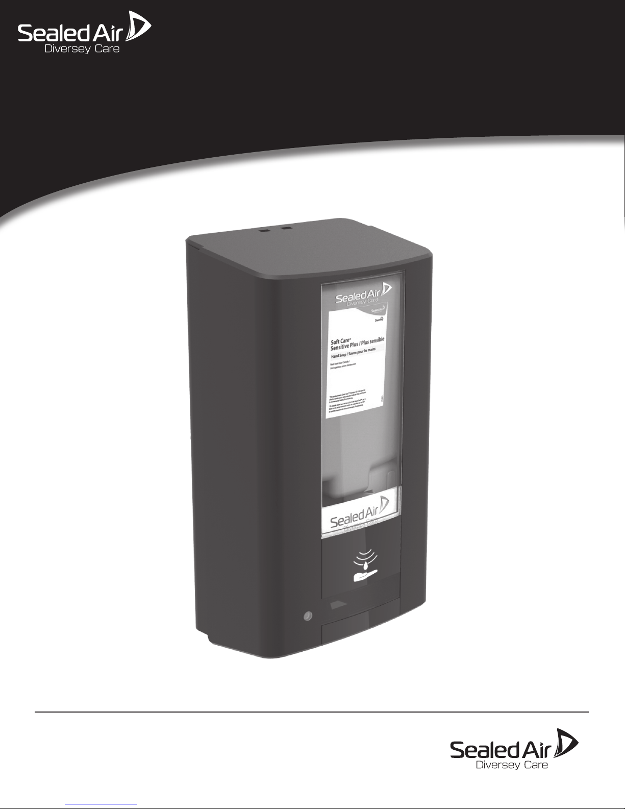
IntelliCare Hybrid Dispenser
UNITED STATES
8215 Forest Point Blvd
Charlotte NC 28273
USA
Phone: +1 (980) 221-3236
www. sealedair.com
CANADA
Address: 3755 Laird Road
Mississauga, Ontario
L5L 0B3 Canada
Phone: +1 (905) 829-1200
www.sealedair.com
EUROPE
Maarssenbroeksedijk 2
NL - 3542DN Utrecht
The Netherlands
Phone: +31 (0)30 247 6911
www.sealedair.com
91-00005_Rev13
1.1 MOUNTING DISPENSER
NOTE: SEE KEY DISPENSER DIMENSIONS BELOW (1.2). IF INSTALLING WITH DRIP-CATCH, SEE CRITICAL DIMENSIONS BELOW (1.5)
Remove key from back of housing. (Reference ‘Key Location’ in section 1.2, below)
The dispenser should be mounted at least 12 inches (30.5cm) above the counter-top, sink or other surface.
If an object remains in the dispenser infrared (IR) sensing range for more than 10 seconds, the white 'PUSH the COVER' decal and GREEN LED will blink and no soap will be
dispensed. Once the object is NO longer in 'view' of the IR (at bottom of dispenser), the dispenser will operate normally.
If replacing soap dispenser on wall, determine if any of the holes match up on the Sealed Air unit. Unit designed to at least partially match numerous soap dispensers.
Go to section 3.0 for specic dispenser mounting instructions.
NOTE : TAPE & SCREWS/ANCHORS ARE PROVIDED. DISCLAIMER :
If rells (Soap) used other than certied SA soap, SA is not responsible for any dispenser issues.
1.2 DIMENSIONS, KEY LOCATION, OPENING & CLOSING DISPENSER
**KEY OUTER DIMENSIONS OF DISPENSER : (H)11.13” [282MM] x (W)6.256” [158MM] x (D)4” [101.6mm]
6.256”
(158mm)
‘click’
push
LABEL FACES OUT
d.
1.3 REFILL PLACEMENT & REMOVAL
IMPORTANT
f.
4”
(101.6mm)
11.13”
(282mm)
a.
Remove cover key (a) from
back of housing.
OPENING COVERKEY LOCATION CLOSING COVER
Insert key in to holes
on top of cover. Pull
cover forward to open.
c.
b.
pull
To close the cover, pull cover from bottom (b) so
that bottom hinge (c) is pulled all the way OUT,
then PUSH the top of cover closed to ‘click’ shut (d).
e.
f.
TO INSERT REFILL TO REMOVE REFILL
Push rell in to place to ensure the FLANGE of the
Soap Nozzle (e) is seated into the correct location (f).
If not, the dispenser will not pump correctly.
1.4 BATTERY INSTALLATION
Insert Sealed Air key (or other item that ts the key hole) at top of cover and pull cover. You now have access to Electronic Module and Batteries.
Remove the battery cover (’a’ - by PULLING cover toward the front) located on the right side of the module (see x-1). Insert 4 C-cell alkaline batteries*
(not included) making sure to place the batteries in the proper orientation as shown by the diagram in the battery compartment (b).
Replace the battery cover.
*(Rechargeable batteries are not to be used. Do not use different types of batteries. New and used batteries are not to be mixed.)
e.
pull
Pull the Container (g) and the Pump
Housing (h). Please recycle accordingly.
x-1 REMOVING BATTERY COVER
g.
h.
b.
a.
The dispenser will turn “on” automatically once batteries are installed. You will get a quick ash of the PUSH icon (x-2) followed immediately by a
ash of the GREEN LED (c) indicating the unit is functional.
NOTE: Low Refill counter will NOT be affected when changing batteries.
When the batteries become too low for the dispenser to function, the “PUSH” icon will illuminate conveying the unit to be used in manual
mode (see x-2) and indicates that the batteries need to be replaced.
Exhausted batteries are to be removed from the dispenser and safely disposed of. If the dispenser is to be stored unused for a long period of time,
remove the batteries.
1.5 OPTIONAL DRIP-CATCH INSTALLATION
FRONT VIEW DRIP-CATCH ATTACHEDREAR VIEW BOTTOM
Insert drip catch hooks (a) through rectangular
slots located at the bottom rear of the dispenser.
The Drip-Catch with SNAP into place.
NOTE:
a. a.
The Drip Catch is not designed to be removed.
However, if going to remove for cleaning please be careful
not to damage the dispenser. The drip catch also might
be damaged after removing.
DISCLAIMER:
If other drip catch used, Sealed Air not responsible for damage.
HYBRID DISPENSER - CRITICAL DIMENSIONS
16.38
416.09
5.61
142.38
101.6
4.0
5.25
133.26
x-2 MANUAL MODE PUSH ICON
c.
5.916
150.28
 Loading...