

Page 1
ASSEMBLY MANUAL
Code : SEA 306N
Specications:
Wingspan-------------------- 81.0 in----------------------- 206.0 cm.
Wing area-------------------- 1200.3 sq.in---------------- 77.4 sq.dm.
Weight------------------------ 26.0 lbs---------------------- 11.8 kg.
Length------------------------ 67.6 in----------------------- 171.6 cm.
Engine------------------------ 55 - 60cc.
Motor size--------------- Motor 360/ 6000watt/ ESC 160A - 200A/ Lipo 12s.
Electric propeller ----------- 24x10 - 25x12.
Radio-------------------------- 6 - 9 channels with 10 servos.
1
Page 2
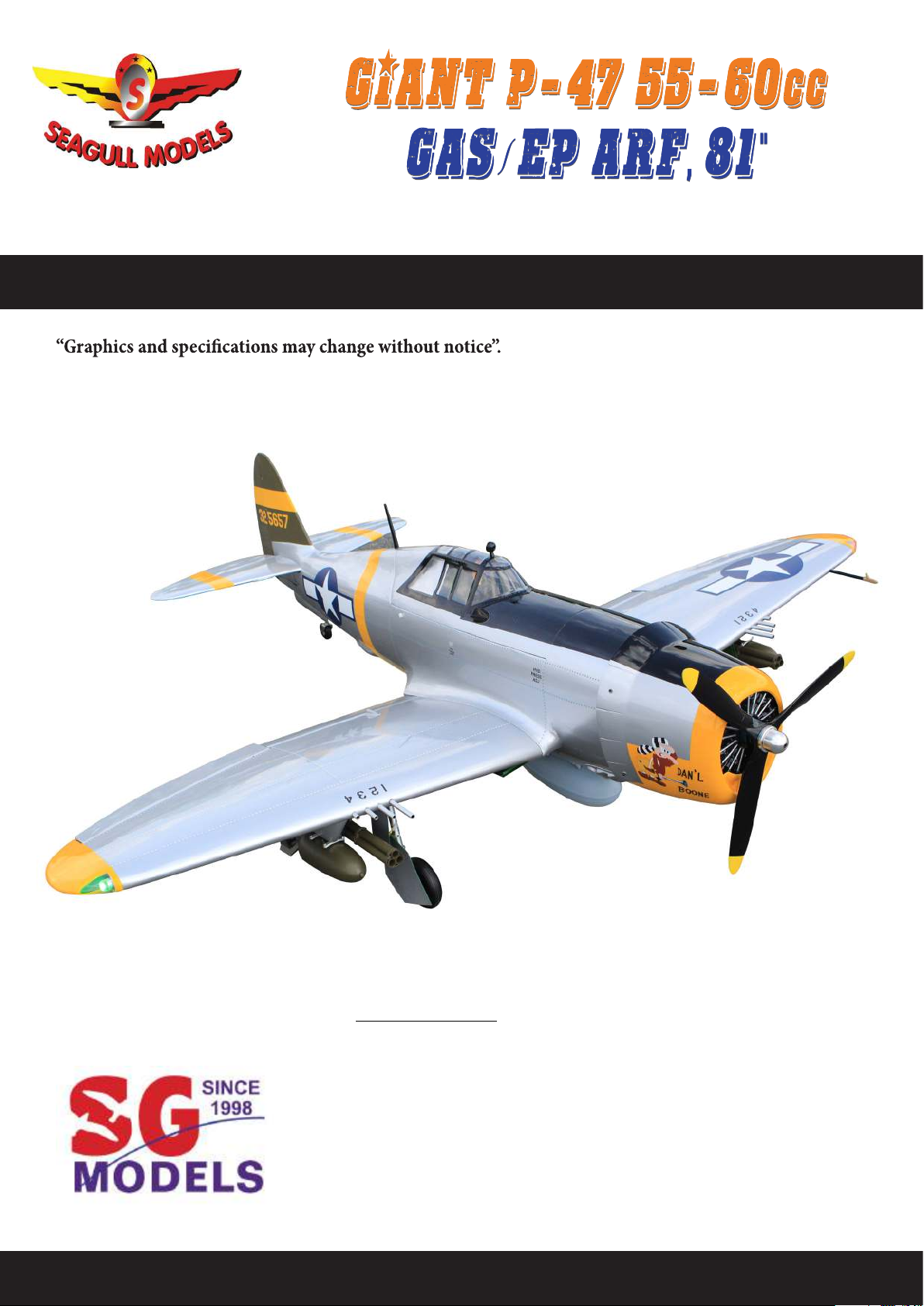
Giant P-47 55-60cc Gas/EP ARF, 81”
INTRODUCTION
ank you for choosing the Giant P-47 55-60cc Gas/EP ARF, 81” ARTF by SG MODELS
. e Giant P-47 55-60cc Gas/EP ARF, 81” was designed with the intermediate/advanced
sport yer in mind. It is a semi scale airplane which is easy to y and quick to assemble. e airframe is conventionally built using balsa, plywood to make it stronger than
the average ARTF, yet the design allows the aeroplane to be kept light. You will nd that
most of the work has been done for you already. e motor mount has been tted and
the hinges are pre-installed. Flying the Giant P-47 55-60cc Gas/EP ARF, 81” is simply a joy.
is instruction manual is designed to help you build a great ying aeroplane. Please read
this manual throughly before starting assembly of your Giant P-47 55-60cc Gas/EP ARF, 81”
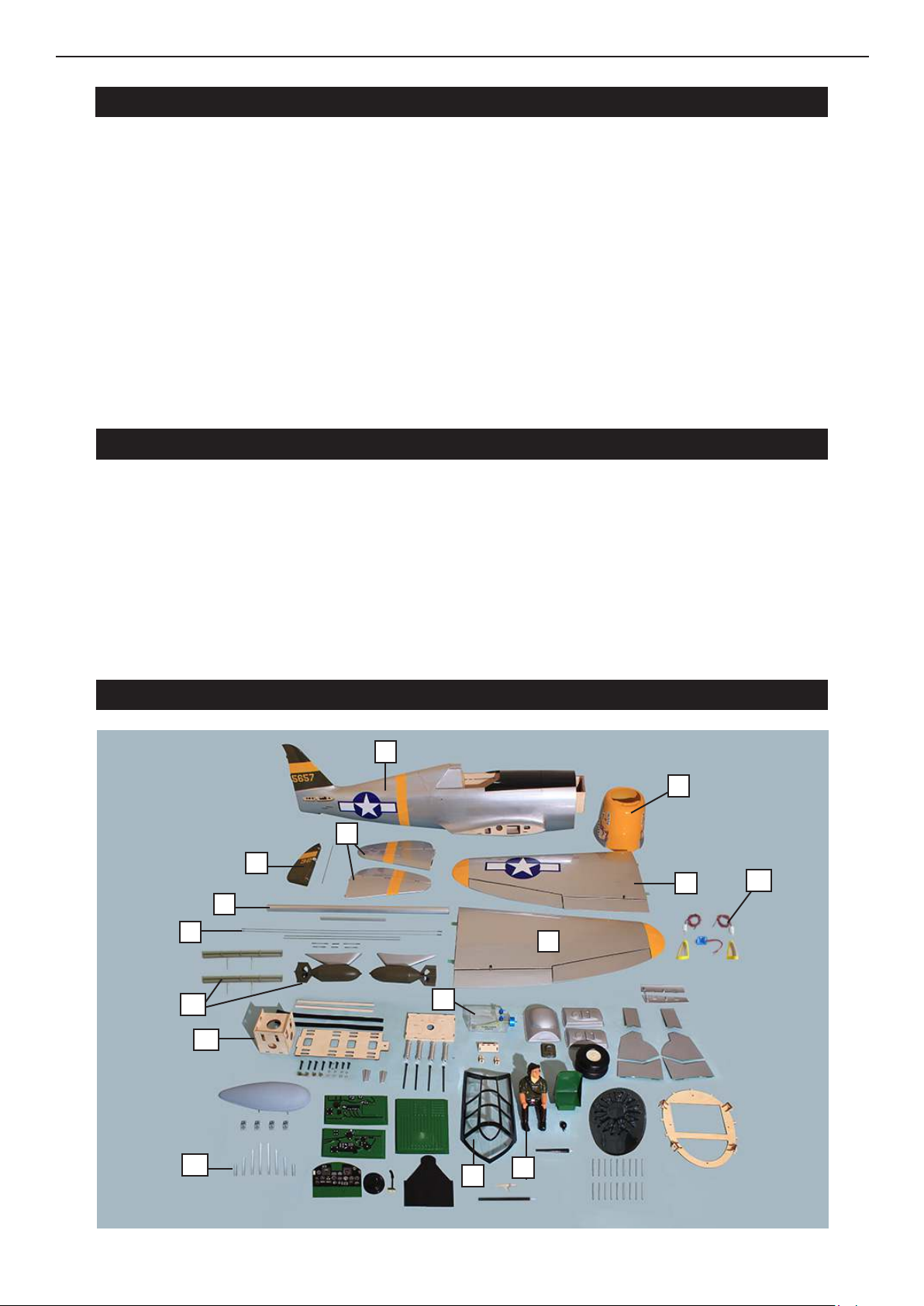
Use the parts listing below to indentify all parts.
WARNING
Please be aware that this aeroplane is not a toy and if assembled or used incorrectly it is capable of causing injury to people or property. WHEN YOU FLY THIS AEROPLANE YOU
ASSUME ALL RISK & REPONSIBILITY.
Instruction Manual.
If you are inexperienced with basic R/C ight we strongly recommend you contact your R/C
supplier and join your local R/C model Flying Club. R/C Model Flying Clubs oer a variety
of training procedures designed to help the new pilot on his way to successful R/C ight.
ey will also be able to advise on any insurance and safety regulations that may apply.
KIT CONTENTS
1
5
3
3
2
12
6
9
11
8
2
10
11
2
4
7
Page 3
KIT CONTENTS
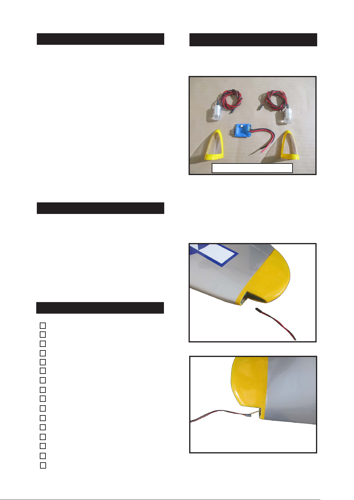
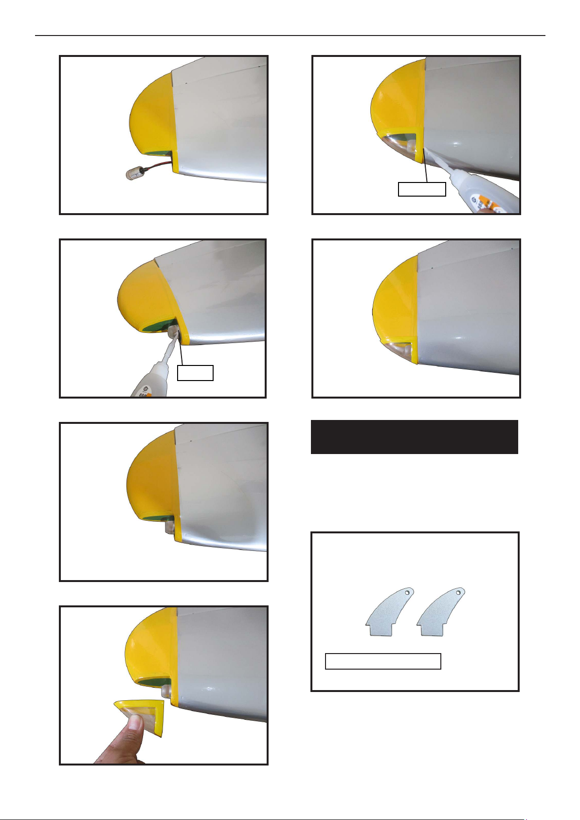
WING TIP BULBS
SEA306N Giant P-47 55-60cc Gas/EP
ARF, 81”
1. Fuselage
2. Wing set (2)
3. Tail set (2)
4. Canopy
5. Cowling
6. Wing tube
7. Pilot
8. Fuel tank
9. Pushrod set
10. Ep Motor box
11. Bomb and gune (2)
12. Wing tip Bulbs
ADDITIONAL ITEMS REQUIRED
� 55-60cc gasoline engine.
� Computer radio 6-9 channel with
10 servos.
� Glow plug to suit engine.
� Propeller to suit engine.
� Protective foam rubber for radio
system.
� Aircra shelves.
TOOLS & SUPPLIES NEEDED
Please see below pictures.
1.
Use Lipo 2s - 3s for led bulbs
e Blue light for right wing tip, and
the red light for le wing tip. ey are designed to operate on voltages 7,4v - 12v.
Connect lights into switch circuit so that
optional the dierent ashes mode.
2.
in cyanoacrylate glue.
Medium cyanoacrylate glue.
30 minute epoxy.
5 minute epoxy.
Hand or electric drill.
Assorted drill bits.
Modelling knife.
Straight edge ruler.
2mm ball driver.
Phillips head screwdriver.
220 grit sandpaper.
90° square or builder’s triangle.
Wire cutters.
Masking tape & T-pins.
read-lock.
Paper towels.
3.
3
Page 4
Giant P-47 55-60cc Gas/EP ARF, 81”
Instruction Manual.
4.
5.
8.
C/A glue
9.
6.
7.
Epoxy
INSTALL THE AILERONS
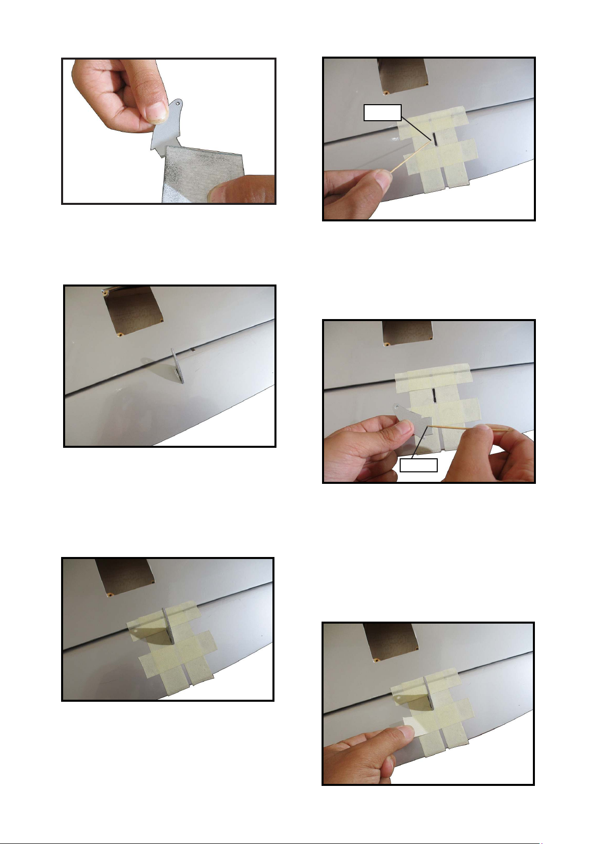
CONTROL HORN
Locate the aileron control horns. e taller
control horn is used for the ailerons, and the
shorter horn for the aps.
1.
AIL AIL
Fiberglass control horn
Use sandpaper to scu the bottom of the
aileron and ap control horns. Use a paper
towel and isopropyl alcohol to remove any
oils or debris from the control horns.
4
Page 5
2.
Check the t of the control horns to the
aileron and ap. ey should rest ush
against the control surface as shown.
3.
5.
Epoxy
Apply epoxy to the area of the control
horns that st into the slots. Use enough
epoxy so the control horns will be fully
bonded to the ed surfaces.
6.
Place low-tack tape 1/32 inch (1mm)
from the control horn slot. is will prevent epoxy from getting on the control
surface when the control horns are glued
in place.
4.
Remove the control horns from the
control surfaces. Apply epoxy to the slot
in the aileron and ap. Make sure the
epoxy gets into the slot for a good bond
between the surfaces and control horn.
Epoxy
Before the epoxy fully cures, remove
the tape from around the control horn.
is will allow the epoxy to ow around
the control horn, creating a small let
between the control horn and surface for
a ished look and secure bond.
7.
5
Page 6
Giant P-47 55-60cc Gas/EP ARF, 81”
Instruction Manual.
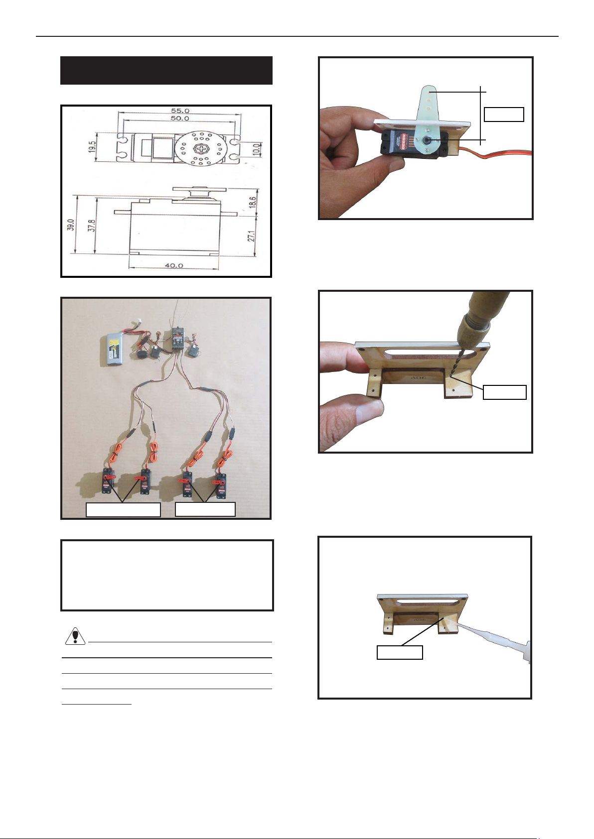
INSTALLING THE AILERON SERVOS
1.
2.
3.
25mm
Use drill bit in a pin vise to drill the mouting holes in the blocks.
4.
Ailerons servo
Maximum Servo spec.
Torque : 126.6 oz-in (9.11 kg-cm) @
6.0V; 178 oz-in (12.82 kg-cm) @ 7.4V;
248 oz-in (17.86 kg-cm) @ 8.4V
Flap servo
Because the size of servos dier, you
may need to adjust the size of the precut
opening in the mount. e notch in the
sides of the mount allow the servo lead to
pass through.
1.5mm
Apply 2-3 drops of thin C/A to each of
the mounting holes. Allow the C/A to
cure without using accelerator.
5.
C/A glue
Place the servo between the mounting
blocks and space it from the hatch. Use
a pencil to mark the mounting hole locations on the blocks.
6
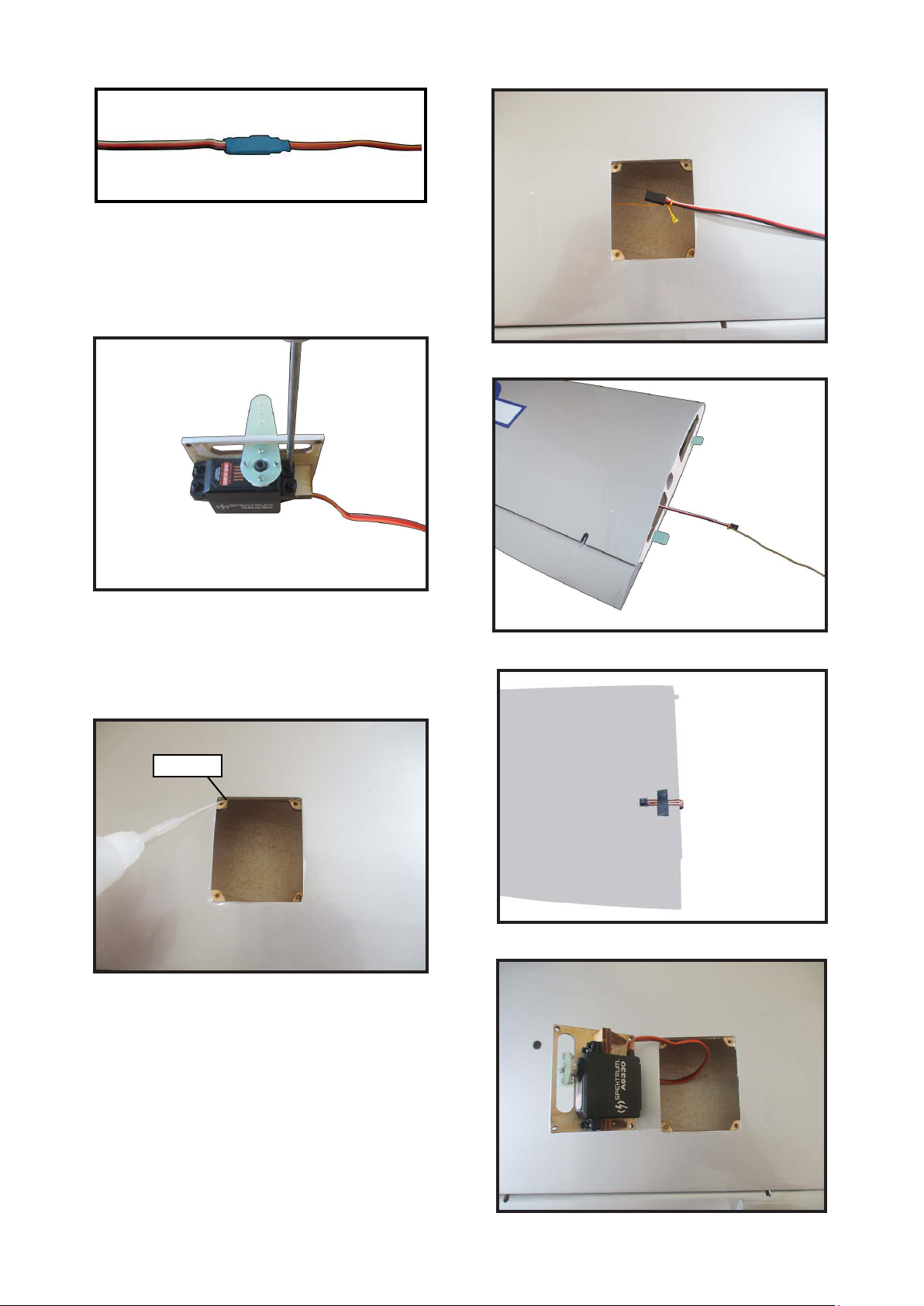
Use dental oss or heatshrunk tube to
secure the connection so they cannot become unplugged.
Page 7
6.
Secure the servo to the aileron hatch using Phillips screwdriver and the screws
provided with the servo.
7.
9 .
10.
Apply 1-2 drops of thin C/A to each of
the mounting tabs. Allow the C/A to cure
without using accelerator.
8.
C/A glue
Remove the string from the wing at the
servo location and use the tape to attach
it to the servo extension lead. Pull the lead
through the wing and remove the string.
11.
12.
7
Page 8
Giant P-47 55-60cc Gas/EP ARF, 81”
Instruction Manual.
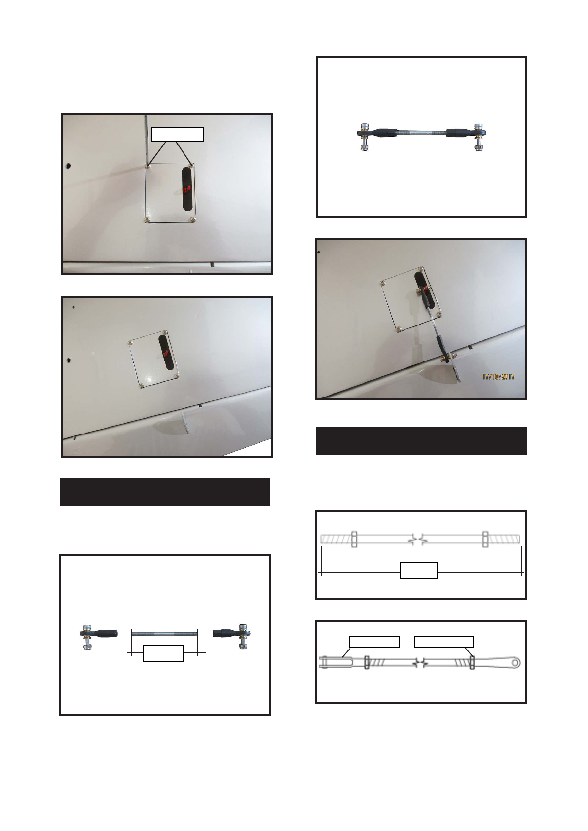
Set the aileron hatch in place and use a
Phillips screw driver to install it with four
wood screws.
13.
M3x10mm
14.
2.
3.
AILERON PUSHROD INSTALLATION
Please see below pictures.
1.
55mm
INSTALLING THE FLAP PUSHROD
Please see below pictures.
1.
70mm
2.
M3 clevis
M3 lock nut
8
Page 9
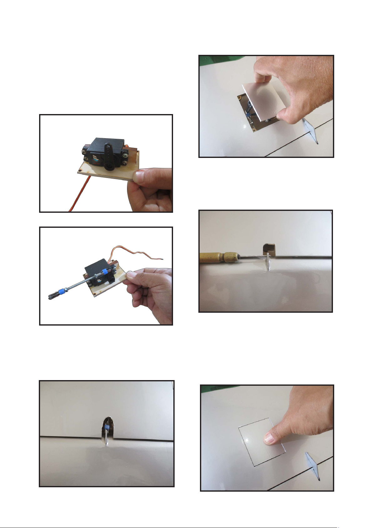
Attach the ap servo to the ap servo
cover. Center the ap servo (or set the
values to 0 for both up and down) and install the servo arm perpendicular to the
servo centerline. e clevis will attach to
the arm 13/16 inches (21mm) from the
center of the arm.
3.
Attach the clevis to the ap servo arm.
6.
Use a pin vise and 3/32-inch (2mm) drill
bit to clear the paint from the ap control
horn.
7.
4.
Attach the ap linkage to the control
horn. Slide the clevis retainer over the
forks of the clevis.
5.
Route the servo lead for the ap servo out
at the root of the wing. Connect the ap
servo to the radio system. With the radio
system on, place the ap servo into position.
8.
9
Page 10
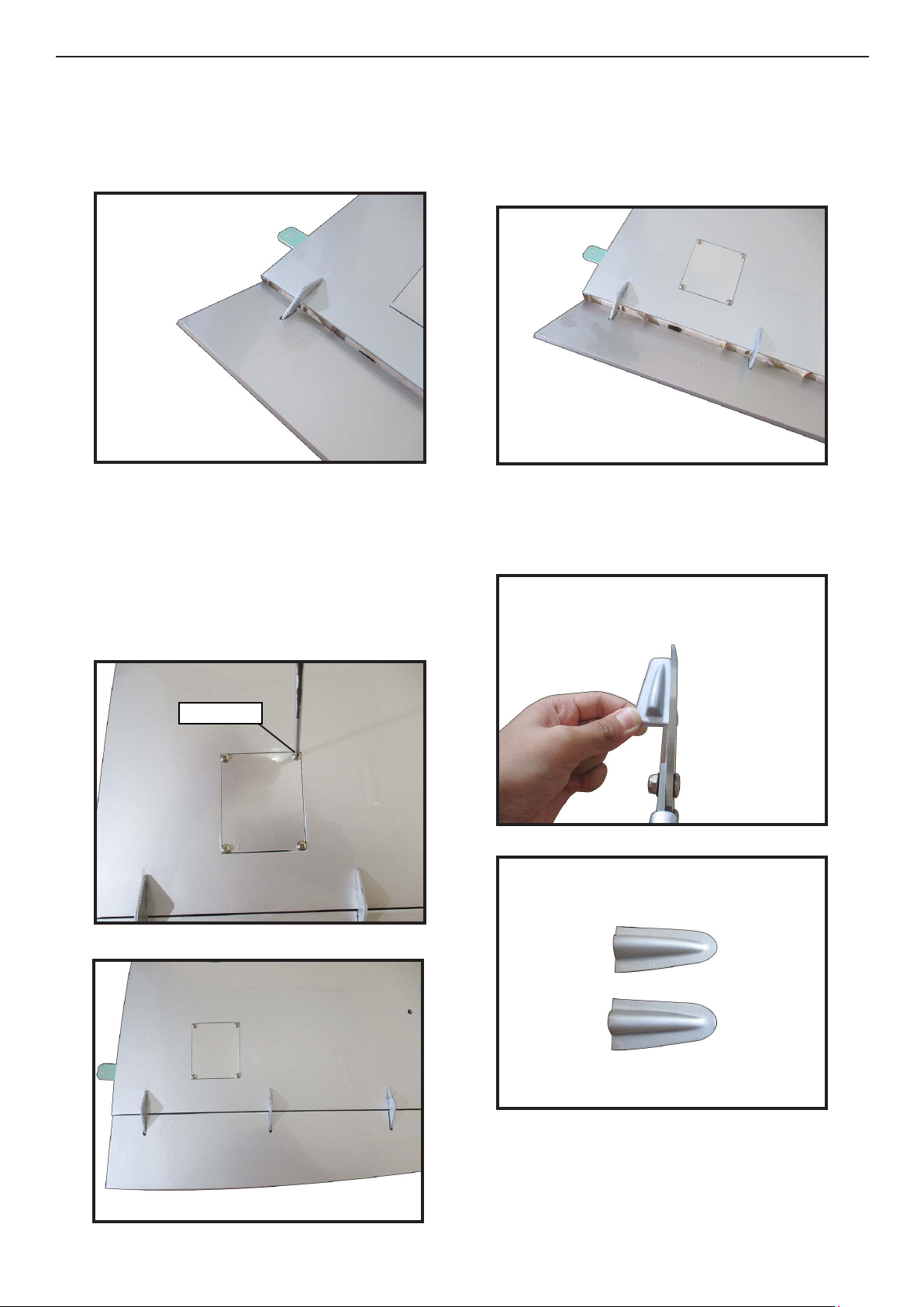
Giant P-47 55-60cc Gas/EP ARF, 81”
Instruction Manual.
Adjust the linkage so the ap is in the
mid-ap position. It may take a few tries
to properly adjust the linkage.
9.
Once adjusted, make sure all clevis retainers are in position. Apply a drop of
threadlock near the clevis, then tighten
the nut against the clevis to keep the linkage from changing length inside the wing.
Set the ap control at the transmitter to
the down ap position. Adjust the ap
travel at the transmitter until it matches
the control throws listed in this manual.
12.
Trim the ap linkage cover using a hobby
knife and hobby scissors.
13.
10.
11.
M3x10mm
14.
10
Fit the ap linkage cover into position.
Check the operation of the ap to make
sure the cover does not interfere with the
ap linkage.
Page 11
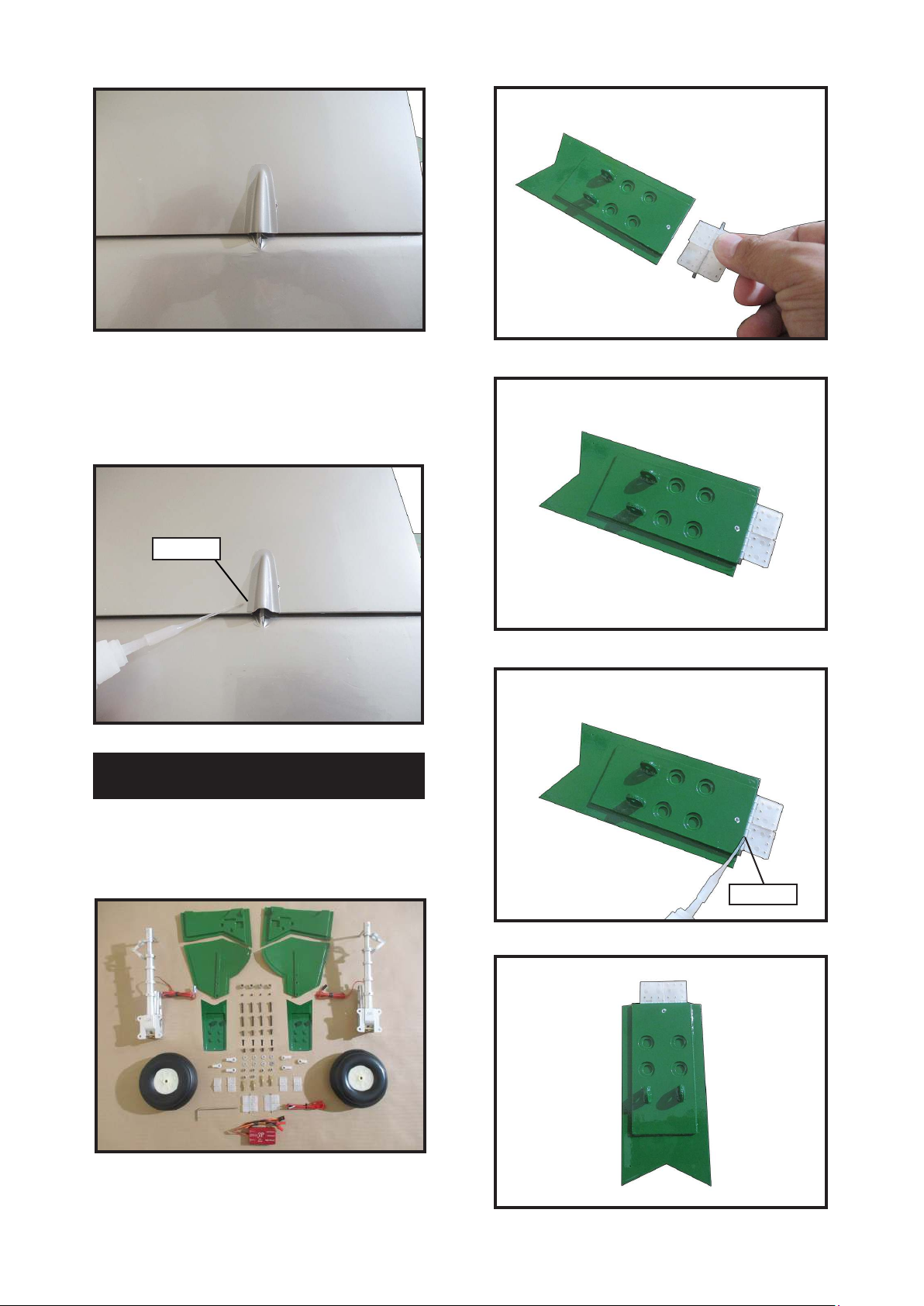
15.
2.
Use canopy glue to attach the cover to the
wing. Use low-tack tape to keep the cover
in position until the adhesive fully cures.
16.
Epoxy
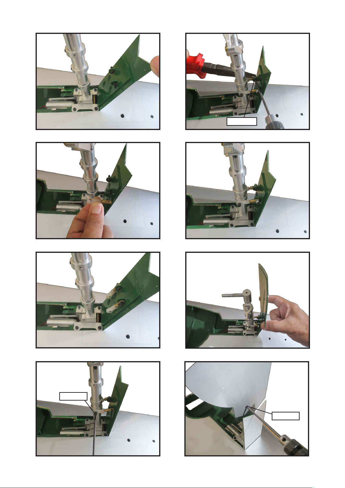
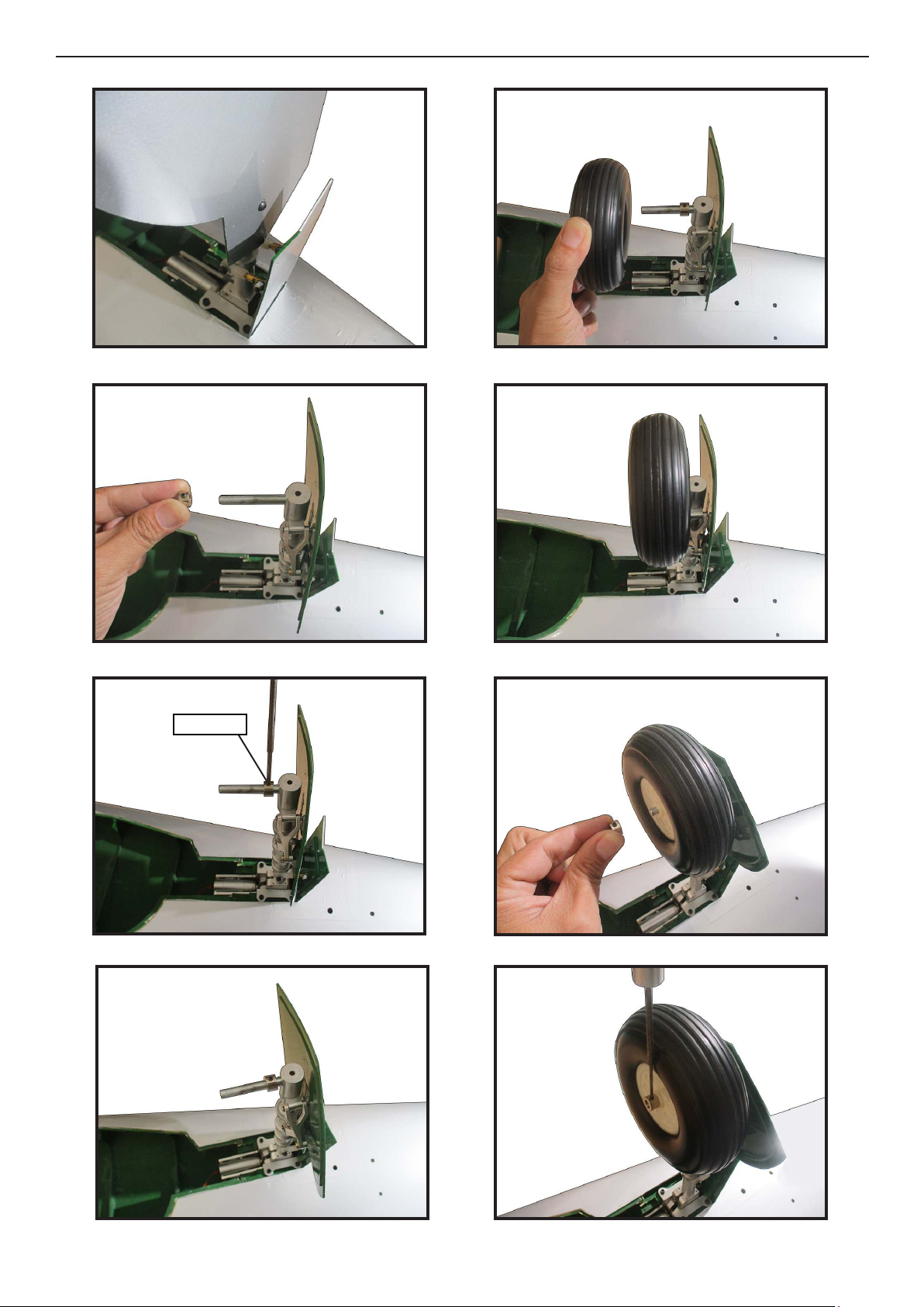
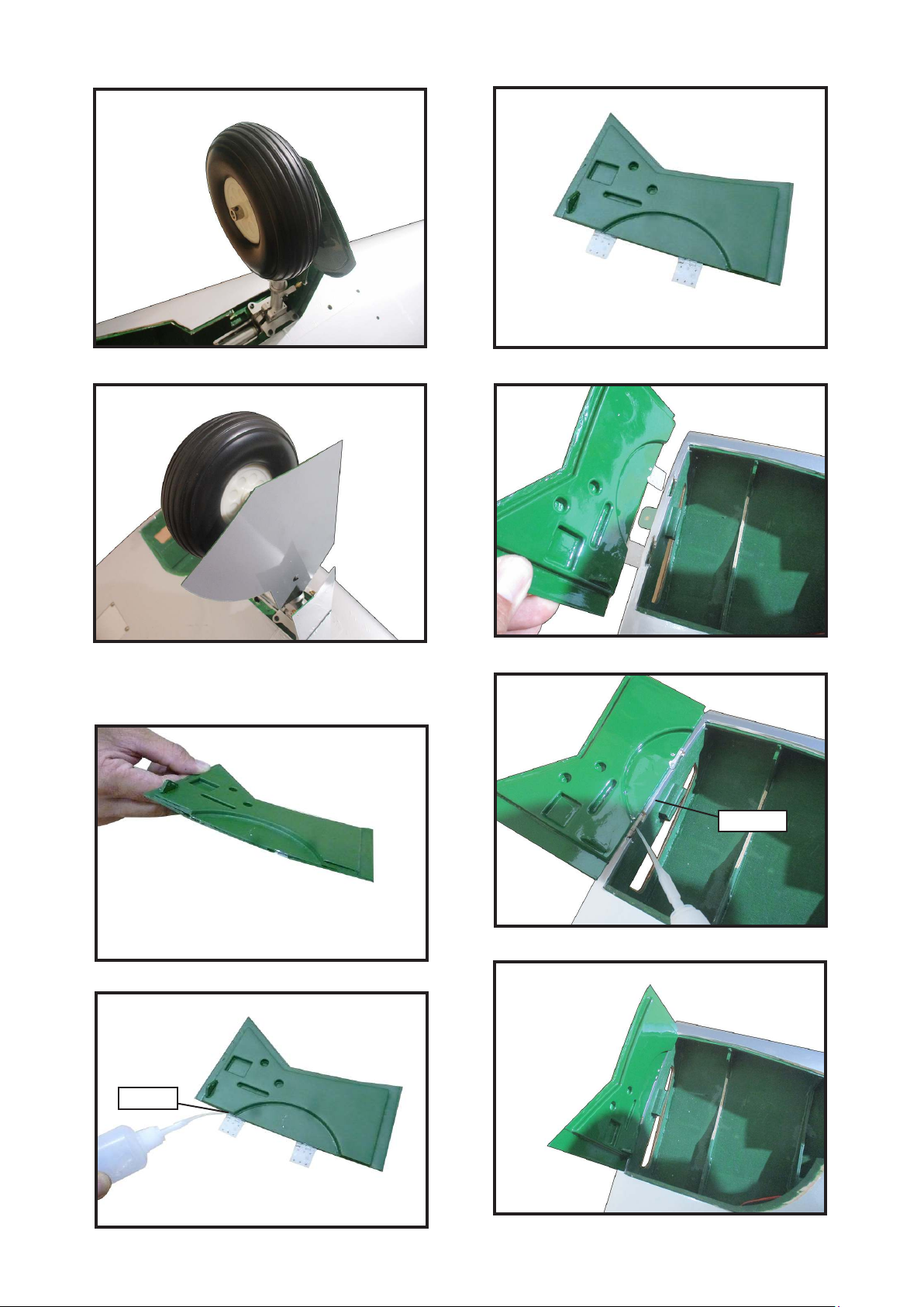
INSTALLING LANDING GEAR
3.
4.
Locate items necessary to install Sprin
Landing Gear.
1.
Install retractable landing gear at the
Wing.
Epoxy
5.
11
Page 12
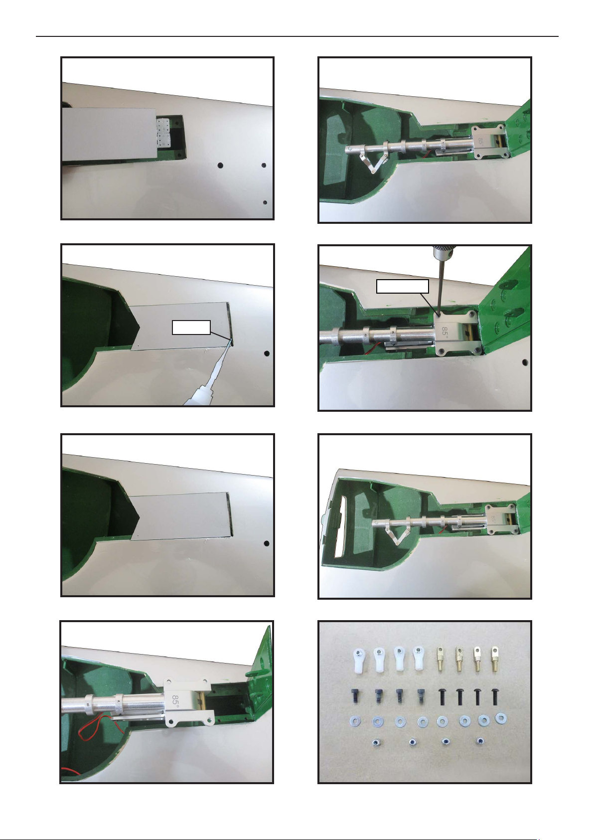
Giant P-47 55-60cc Gas/EP ARF, 81”
Instruction Manual.
6.
7.
10.
11.
M3x20mm
Epoxy
8.
9.
12.
13.
12
Page 13
14.
18.
M3x10mm
15.
16.
19.
20.
17.
21.
M3x8mm
M3x6mm
13
Page 14
Giant P-47 55-60cc Gas/EP ARF, 81”
Instruction Manual.
22.
23.
26.
27.
24.
25.
28.
M3x4mm
29.
14
Page 15
30.
34.
31.
Install the cap on the wing.
32.
35.
36.
Epoxy
33.
37.
Epoxy
15
Page 16
Giant P-47 55-60cc Gas/EP ARF, 81”
Instruction Manual.
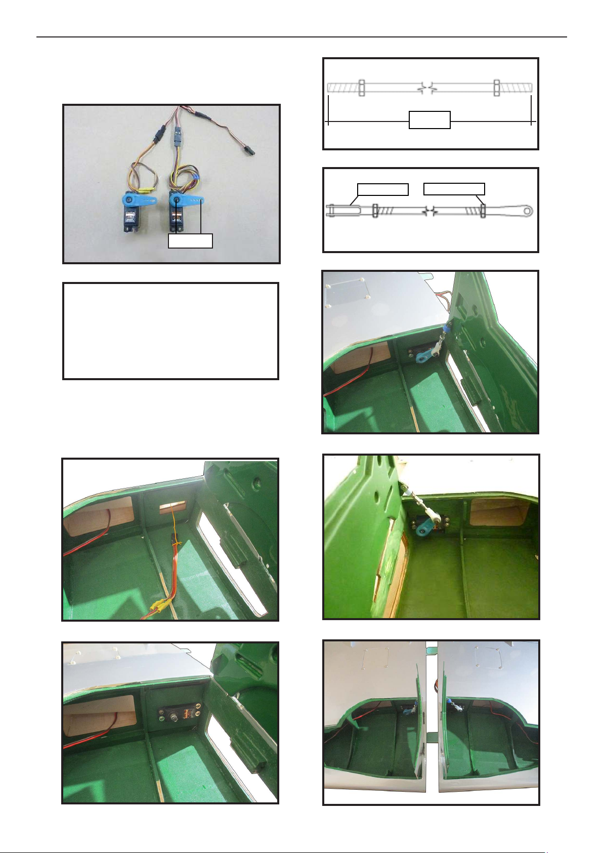
e servo motor should be at least 25mm
in size.
38.
25mm
Mininum servo.
Tor qu e : 8.7 oz-in (6.3 kg-cm) @ 6V;
118 oz-in (8.5 kg-cm) @ 8.4V
Encourage the use of servos such as
Spektrum.a5060.
41.
42.
43.
M3 clevis
30mm
M3 lock nut
Note: e speed of this servo you to be in
the slowest mode then you gradually increase to suit the speed ranked.
39.
40.
44.
45.
16
Page 17
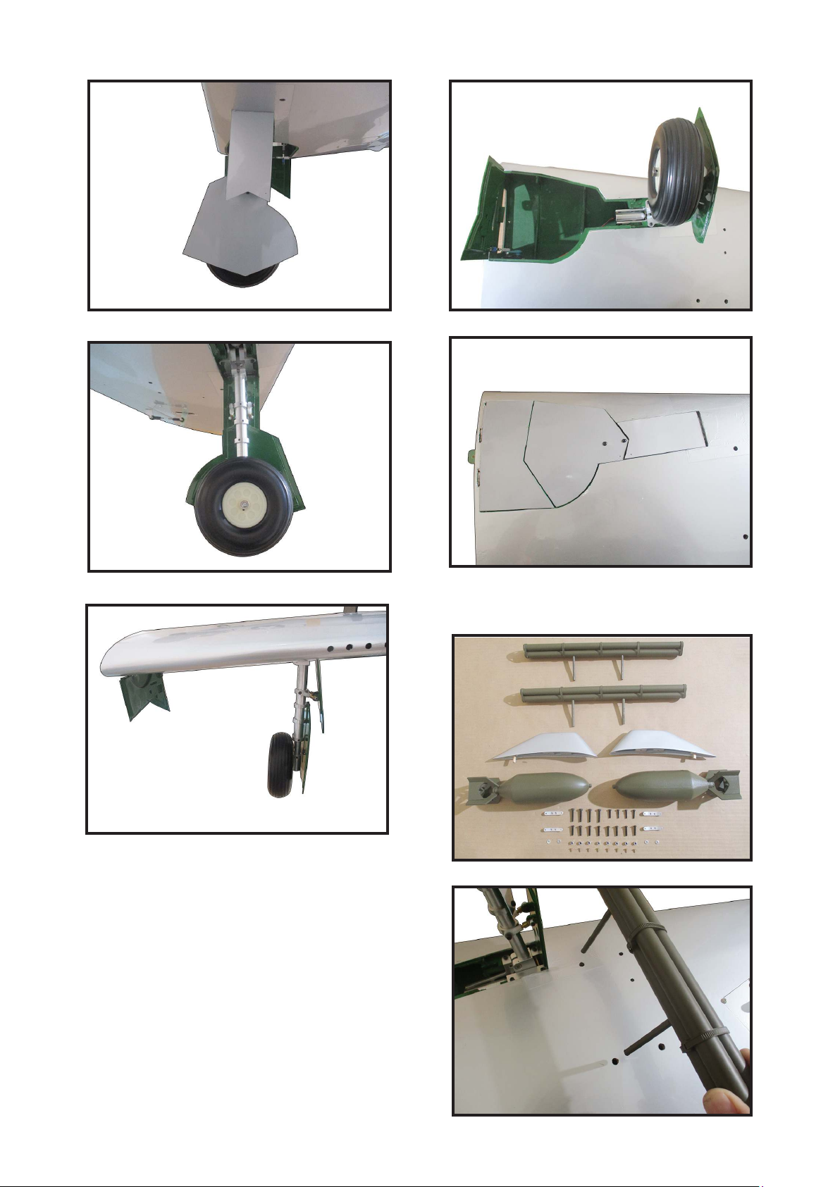
46.
49.
47.
48.
50.
Insert bombs and guns on wings.
51.
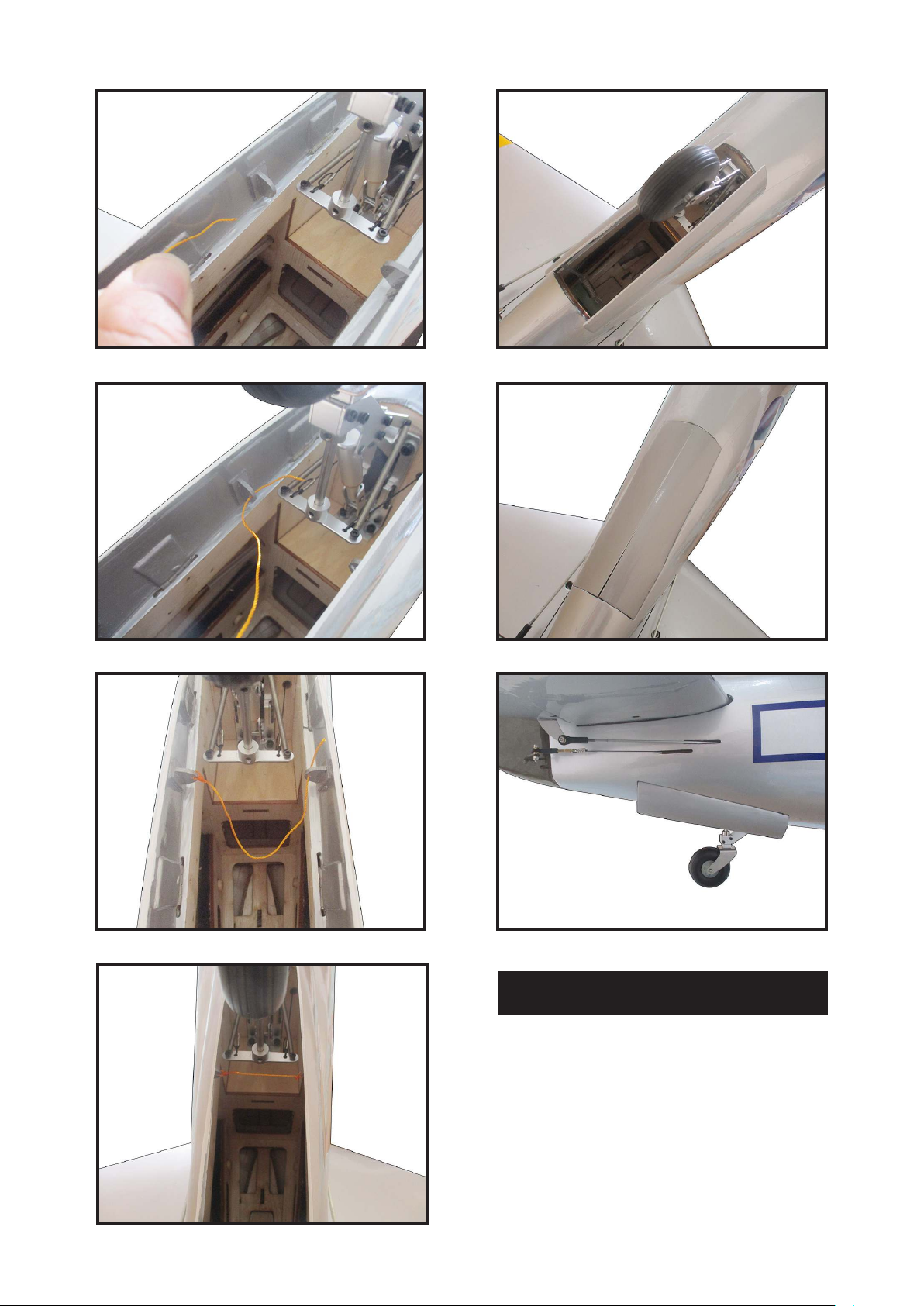
Secure the landing gear doors to the landing gear struts.
52.
17
Page 18
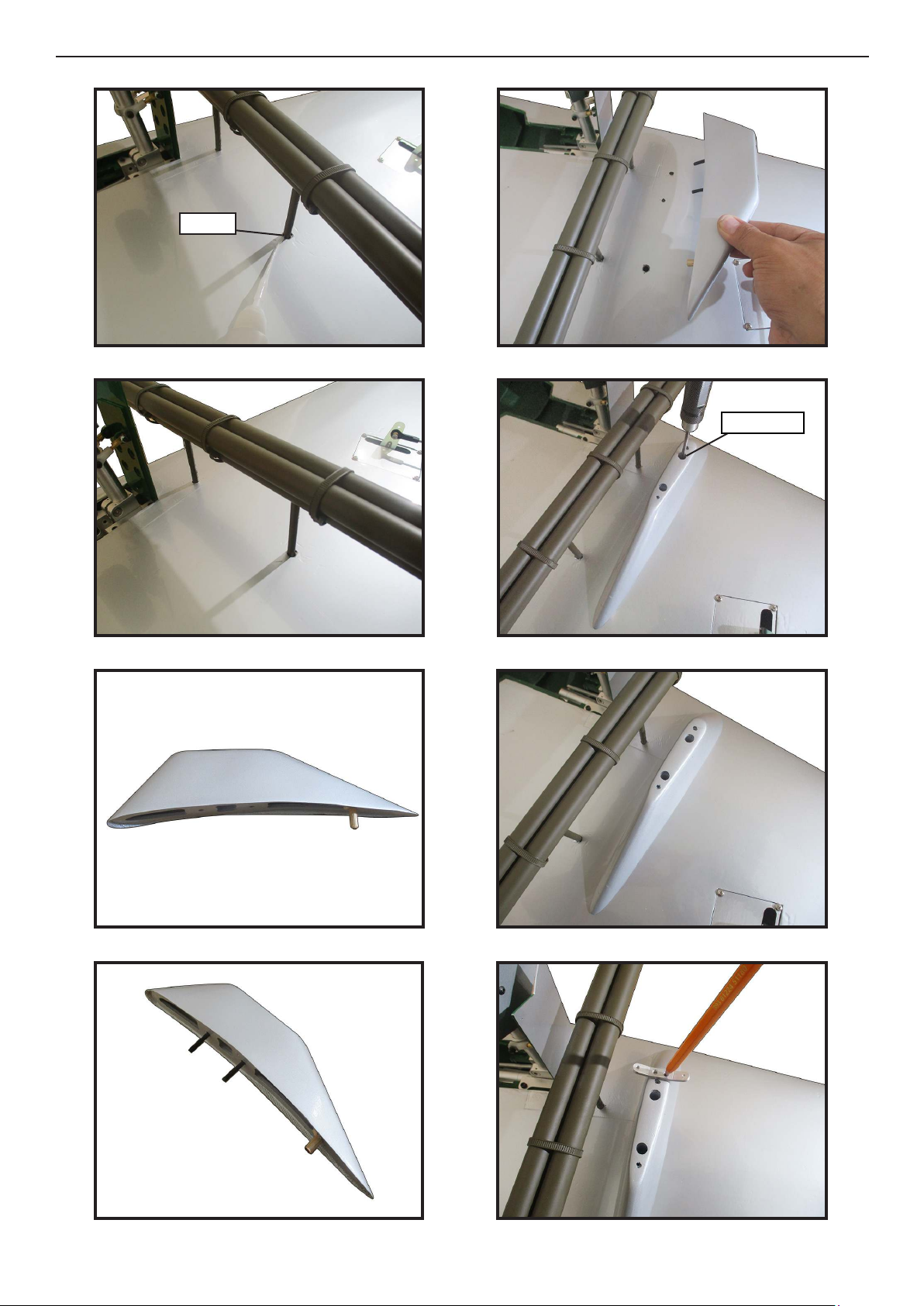
Giant P-47 55-60cc Gas/EP ARF, 81”
Instruction Manual.
53.
54.
57.
Epoxy
58.
M4x15mm
55.
56.
59.
60.
18
Page 19
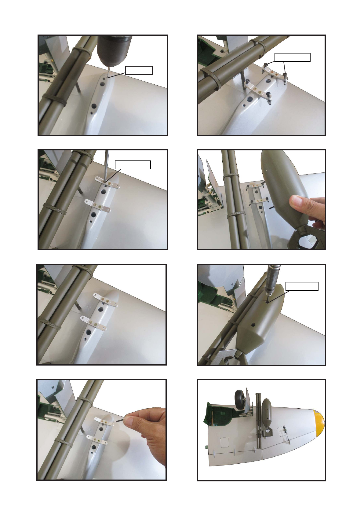
1.5mm
65.61.
M3x20mm
62.
63.
66.
M2.5x10mm
67.
M3x25mm
64.
68.
19
Page 20
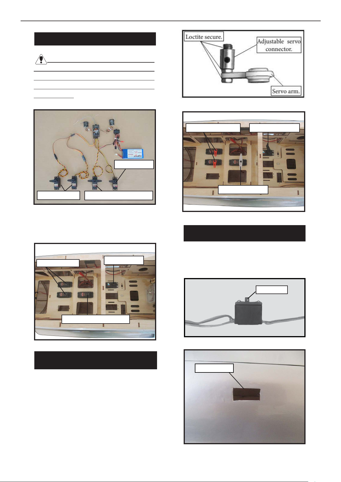
Giant P-47 55-60cc Gas/EP ARF, 81”
INSTALLING THE FUSEKAGE SERVOS
Because the size of servos dier, you
may need to adjust the size of the precut
opening in the mount. e notch in the
sides of the mount allow the servo lead to
pass through.
Instruction Manual.
1.
.
1.
rottle servo
Elevator servo
Rudder servo + Tail wheel
Secure the servos with the screws provided with your radio system.
2.
Elevator servo
rottle servo
2.
Elevator servo arm
Rudder servo arm
rottle servo arm
INSTALLING THE RECEIVER SWITCH
Install the switch into the precut hole in
the side, in the fuselage.
Rudder servo + Tail wheel
THROTTLE SERVO ARM
INSTALLATION
.
Install adjustable servo connector in the
servo arm as same as picture below:
1.
3/32” Hole.
2.
Trim and cut
20
Page 21
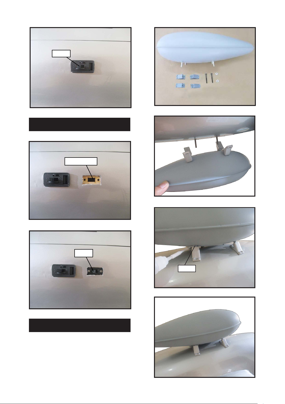
3.
Switch
INSTALLING THE ENGINE SWITCH
1.
Trim and cut
1.
2.
2.
Switch
INSTALL SCALE BOMB
Locate items necessary to install.
3.
Epoxy
4.
21
Page 22
Giant P-47 55-60cc Gas/EP ARF, 81”
Instruction Manual.
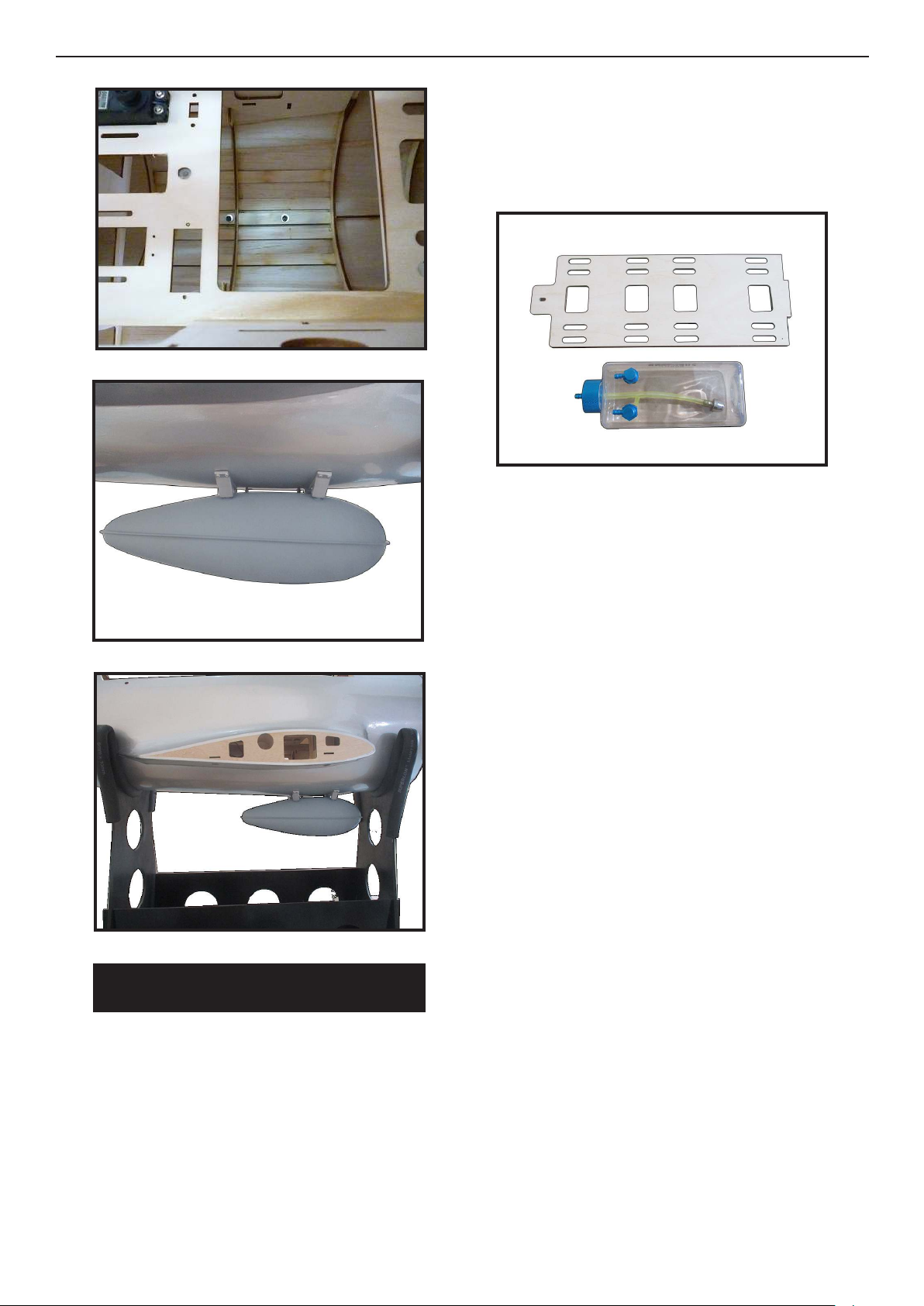
5.
6.
Using a modeling knife, cut one length of
silicon fuel line. Connect one end of the
line to the weighted fuel pick up and the
other end to the nylon pick up tube.
1.
Carefully bend the second nylon tube up at a
45º angle. is tube is the vent tube.
7.
INSTALLING THE STOPPER
ASSEMBLY
Test t the stopper assembly into the tank.
It may be necessary to remove some of the
ashing around the tank opening using a
modeling knife. If ashing is present, make
sure none falls into the tank.
With the stopper assembly in place, the
weighted pick-up should rest away from the
rear of the tank and move freely inside the
tank. e top of the vent tube should rest just
below the top of the tank. It should not touch
the top of the tank.
When satised with the alignment of the
stopper assembly tighten the 3 x 20mm machine screw until the rubber stopper expands
and seals the tank opening. Do not overtighten the assembly as this could cause the tank
to split.
Using a modeling knife, carefully cut o
the rear portion of one of the 3 nylon
tubes leaving 1/2” protruding from the
rear of the stopper. is will be the fuel
pick up tube.
22
Page 23
FUEL TANK INSTALLATION
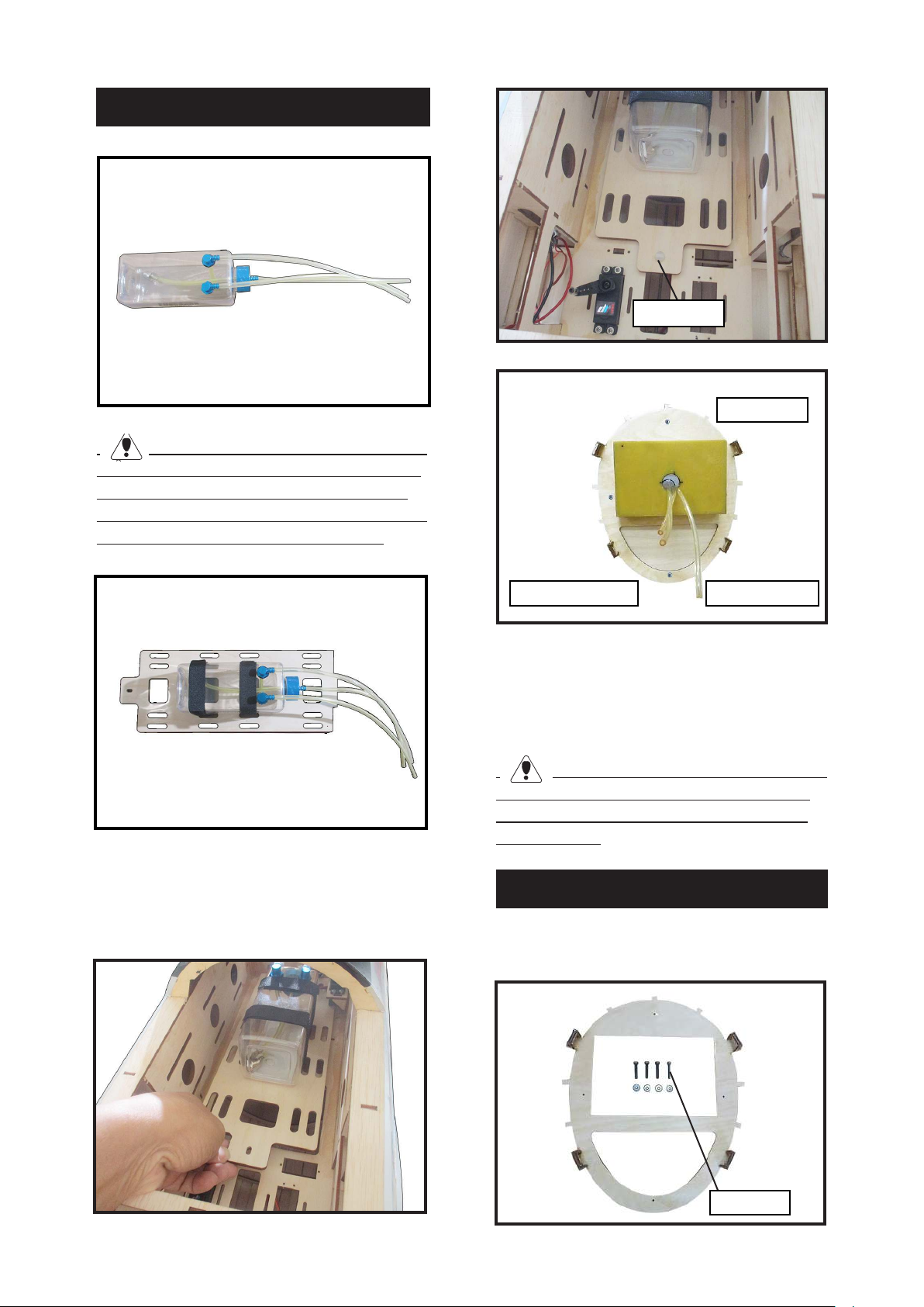
1.
You should mark which tube is the vent
and which is the fuel pickup when you attach
fuel tubing to the tubes in the stopper. Once
the tank is installed inside the fuselage, it may
be dicult to determine which is which.
4.
M4 Nylon
5.
Vent tube
2.
Slide the fuel tank into the fuselage. Guide
the lines from the tank through the hole in
the ewall.
3.
Fuel pick up tube Fuel ll tube
Connect the lines from the tank to the engine and muer. e vent line will connect to the muer and the line from the
clunk tothe carburetor.
Blow through one of the lines to ensure
the fuel lines have not become kinked inside
the fuel tank compartment. Air should ow
through easily.
MOUNTING THE ENGINE
Please see below pictures.
1.
3x15mm
23
Page 24
Giant P-47 55-60cc Gas/EP ARF, 81”
Instruction Manual.
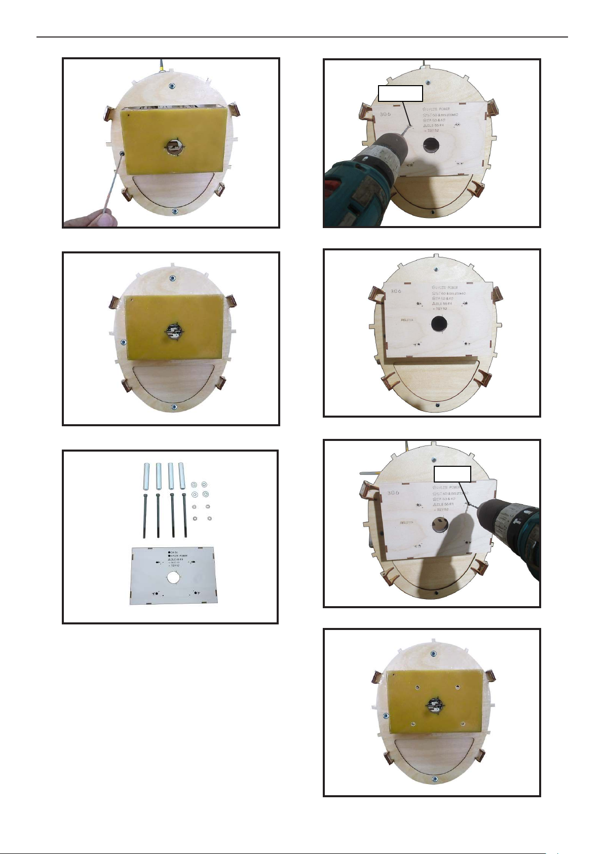
2.
3.
5.
2.5mm
6.
4.
Locate the engine mounting in position on
the rewall. Use a 2.5mm drill bit to drill the
holes necessary to mount your particular
motor choice.
7.
7mm
8.
24
Page 25
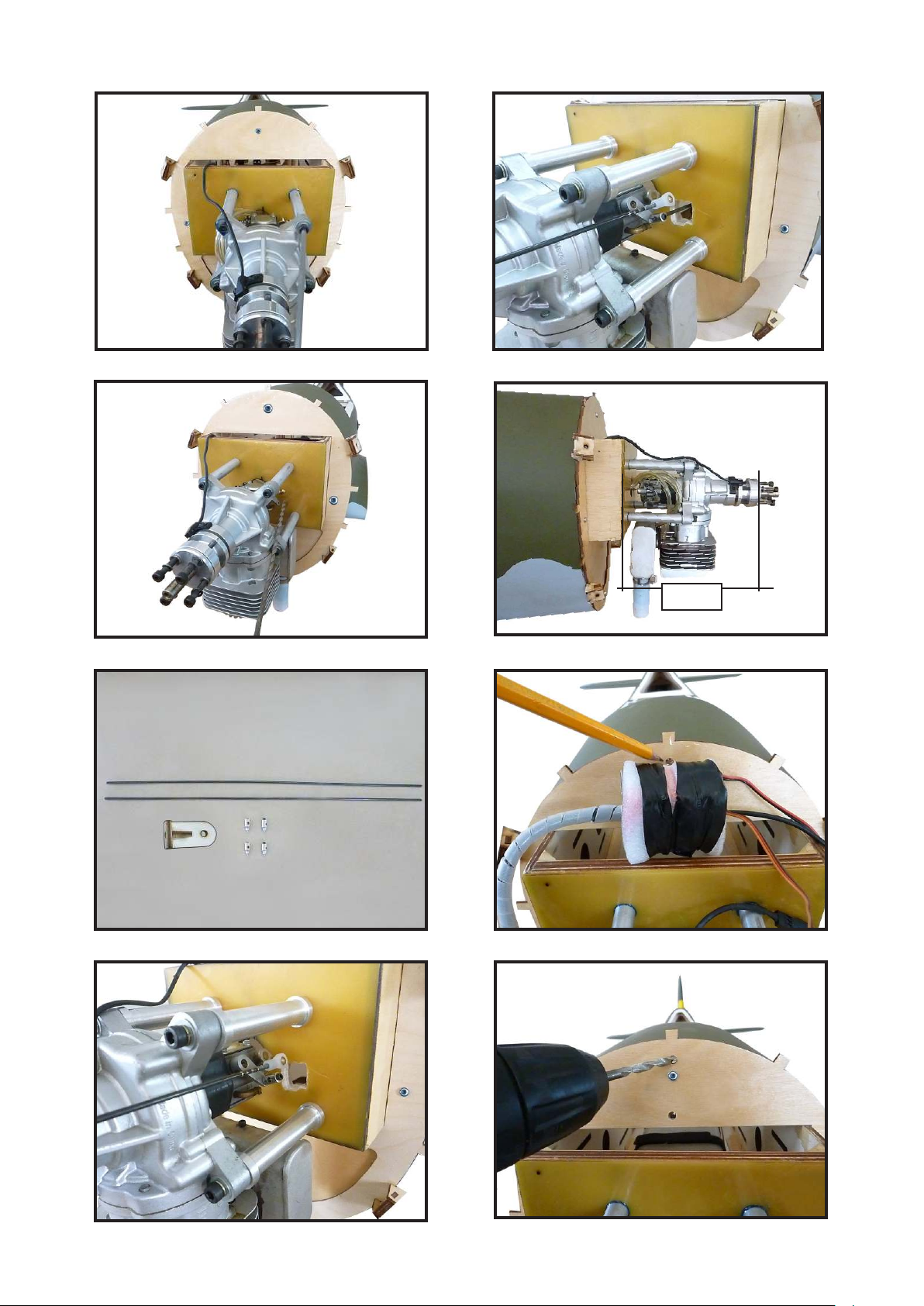
9.
13.
10.
11.
14.
170mm
15.
12.
16.
25
Page 26
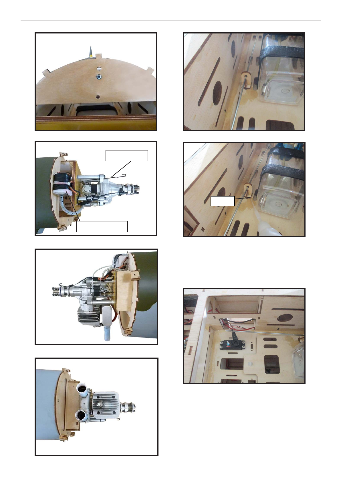
Giant P-47 55-60cc Gas/EP ARF, 81”
Instruction Manual.
17.
18.
21.
22.
Pushrod wire
Epoxy
19.
20.
Ignition Modude
Use medium CA to glue the pushrod
stando to the inside of the fuselage and
the pushrod tube.
23.
26
Page 27
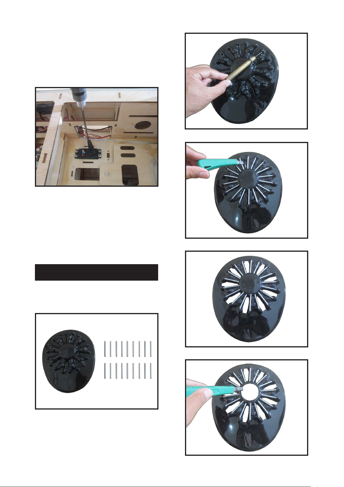
Reinstall the servo horn by sliding the
connector over the pushrod wire. Center
the throttle stick and trim and install the
servo horn perpendicular to the servo
center line.
24.
Move the throttle stick to the closed position and move the carburetor to closed.
Use a 2.5mm hex wrench to tighten the
screw that secures the throttle pushrod
wire. Make sure to use threadlock on the
screw so it does not vibrate loose.
2.
3.
4.
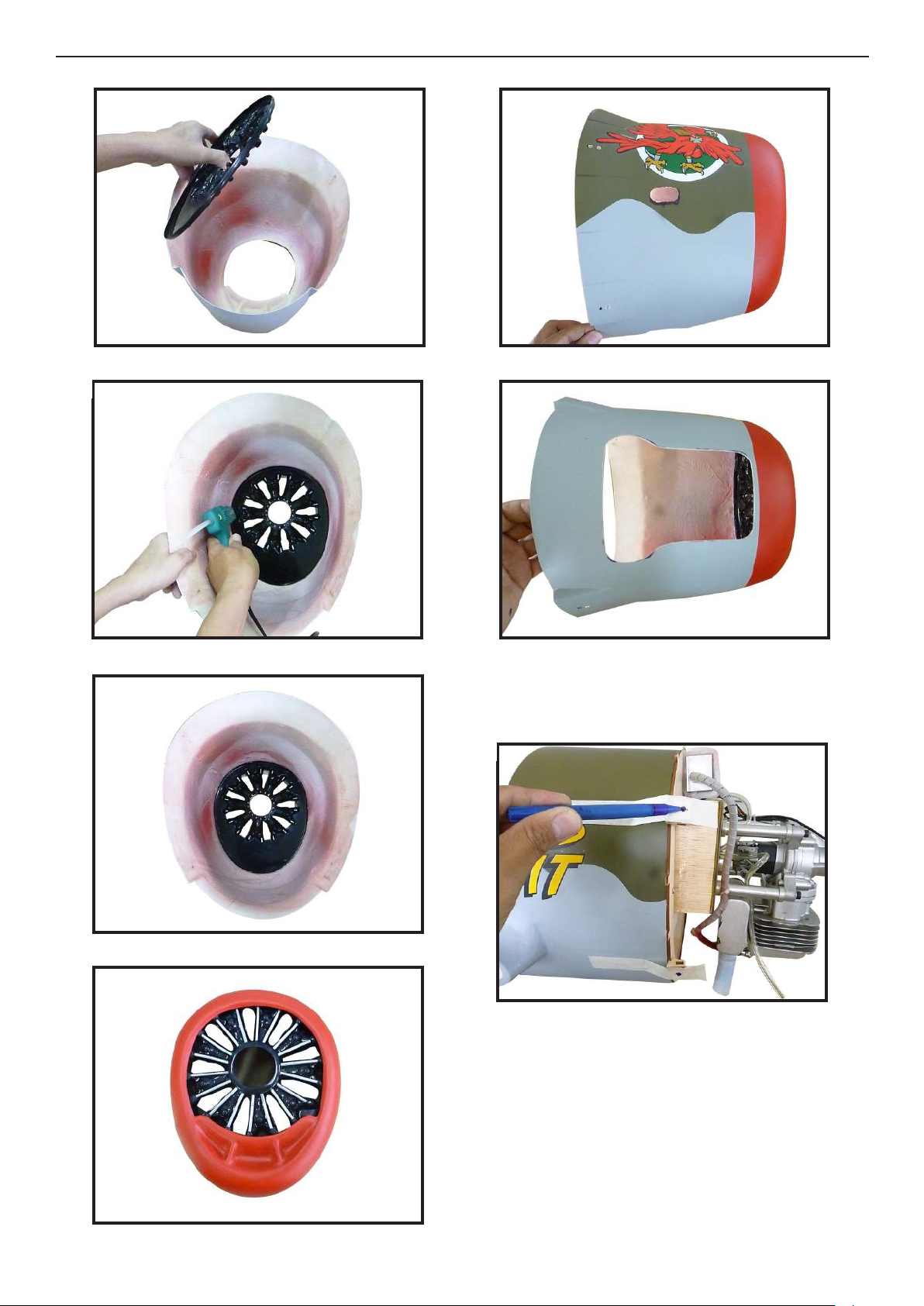
COWLING
Please see below pictures.
1.
5.
27
Page 28
Giant P-47 55-60cc Gas/EP ARF, 81”
Instruction Manual.
6.
7.
10.
11.
8.
9.
Tape the cowl to the fuselage using lowtack tape.
12.
28
Page 29
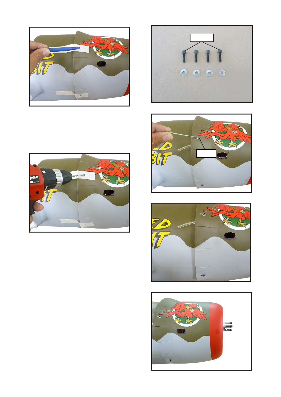
13.
15.
3x10mm
Use a drill and drill bit to drill the holes
for the cowl mounting screws. Make sure
the cowl position is correct before drilling each hole.
14.
Install the muer and muer extension
onto the engine and make the cutout in
the cowl for muer clearance. Connect
the fuel and pressure lines to the carburetor, muer and fuel ler valve. Secure
the cowl to fuselage using the M3x10mm
socket head screws.Putting a small length
of silicon fuel tube under the head of the
screw helps with vibration.
16.
Loctite
17.
18.
29
Page 30
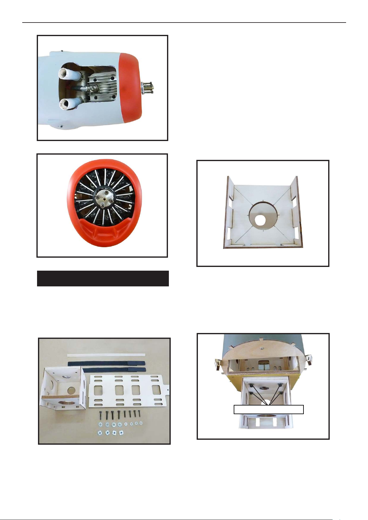
Giant P-47 55-60cc Gas/EP ARF, 81”
Instruction Manual.
19.
20.
- Motor: 360 - 6000 Watts
- Propeller: 24x10 ~ 25x12
- ESC: 160A - 200A
- 12S Lipo
Attach the electric motor box to the rewall centered with the cross lines drawn
on the electric motor box and rewall.
Using M5x30mm to secure the motor box
to the rewall. Please see pictures below.
2.
ELECTRIC POWER CONVERSION
Locate the items neccessary to install the
electric power conversion included with
your model.
1.
Attach the motor mount to the front of the
electric motor box using four 5mm blind
nut, four M5x30mm hex head bolts to secure the motor. Please see picture shown.
3.
M5x30mm and washers.
Recommend the items necessary to install
the electric power conversion parts
included with your model.
30
Page 31
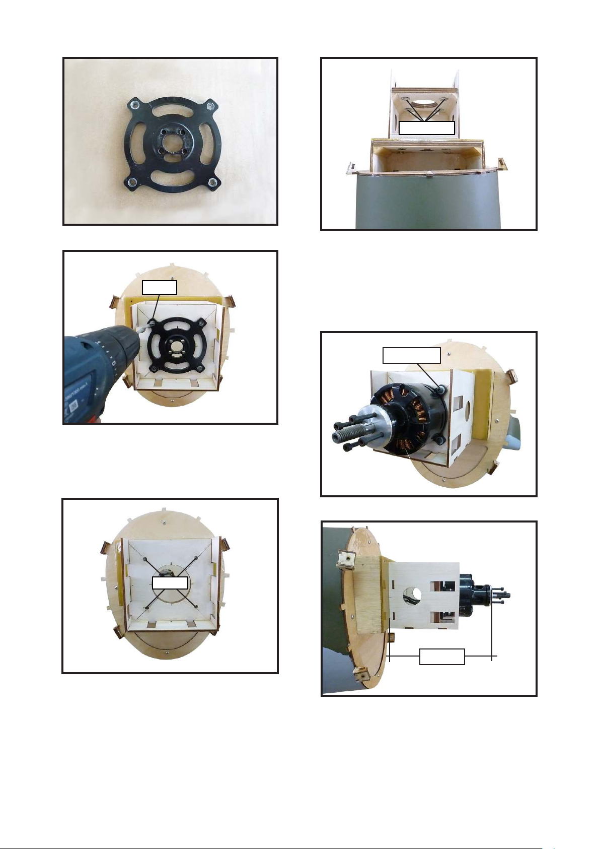
4.
7.
Blind nut
5.
5mm
en, use 7mm drill bit to enlarge the
holes on the electric motor box.
6.
Attach the motor to the front of the electric motor box using four 5mm blind nut,
four M5x20mm hex head bolts to secure
the motor. Please see picture shown.
8.
M5x20mm
9.
7mm
170mm
31
Page 32
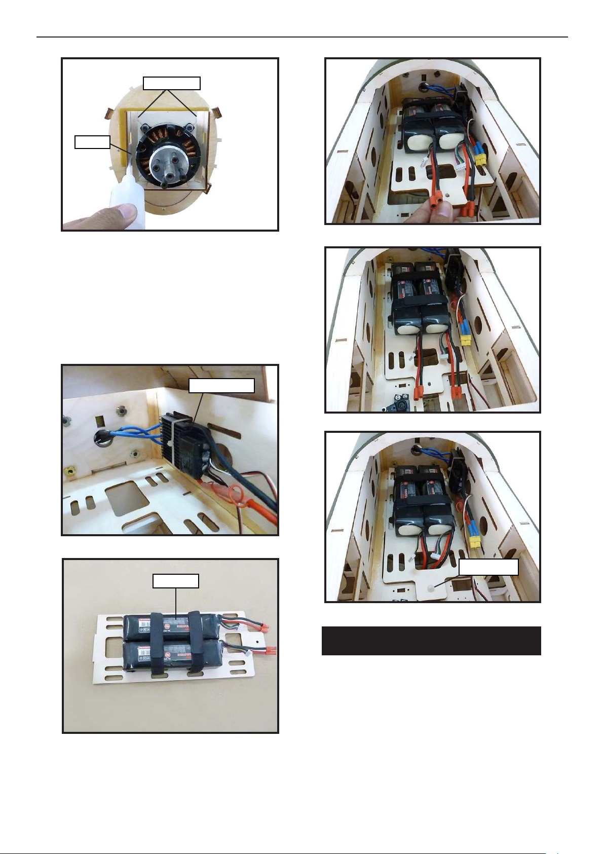
Giant P-47 55-60cc Gas/EP ARF, 81”
Instruction Manual.
10.
Balsa stick
Epoxy
Attach the speed control to the side of
the motor box using two-sided tape and
tie wraps. Connect the appropriate leads
from the speed control to the motor. Make
sure the leads will not interfere with the
operation of the motor.
13.
14.
11.
12.
Speed control
15.
M4 Nylon
Battery
INSTALLING THE SPINNER
32
Install the spinner backplate, propeller
and spinner cone.
Page 33
1.
2.
Epoxy
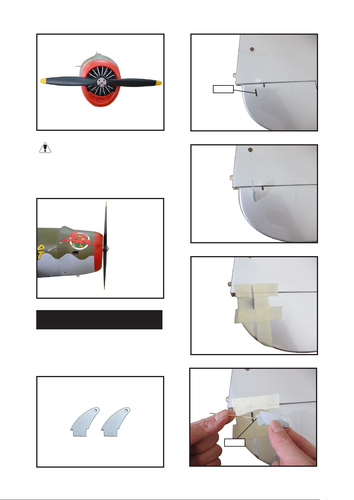
e propeller should not touch any
part of the spinner cone. If it does, use a
sharp modeling knife and carefully trim
away the spinner cone where the propeller comes in contact with it.
2.
3.
4.
INSTALL ELEVATOR CONTROL HORN
Install the elevator control horn using the
same method as same as the aileron control horns.
1.
ELV E LV
5.
Epoxy
33
Page 34
Giant P-47 55-60cc Gas/EP ARF, 81”
Instruction Manual.
6.
7.
2.
Epoxy
Epoxy
3.
Epoxy
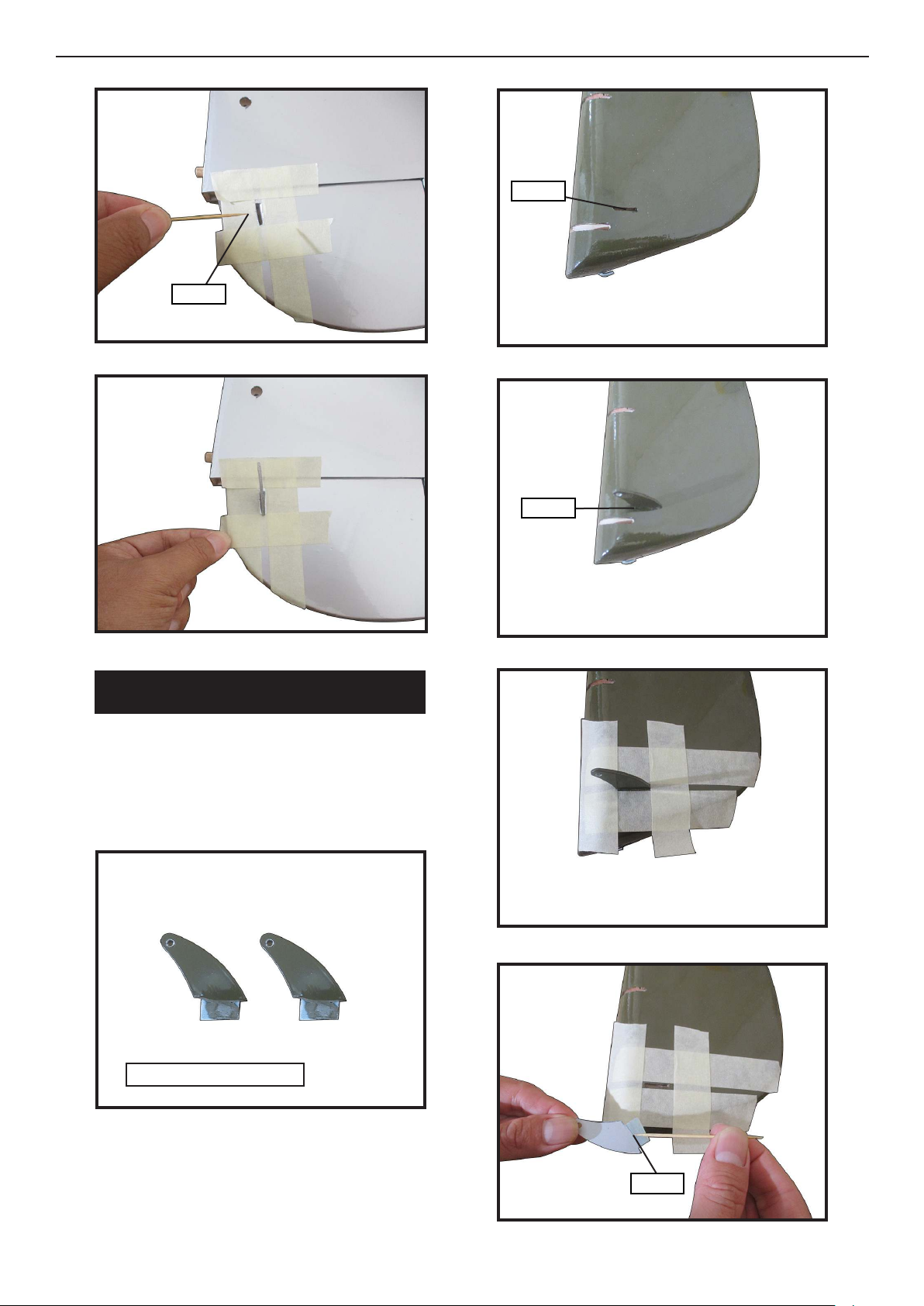
INSTALL RUDDER CONTROL HORN
Install the elevator control horn using the
same method as same as the aileron control horns.
1.
RUD RUD
Fiberglass control horn
4.
5.
34
Epoxy
Page 35
6.
10.
Epoxy
7.
8.
11.
Fiberglass control horn
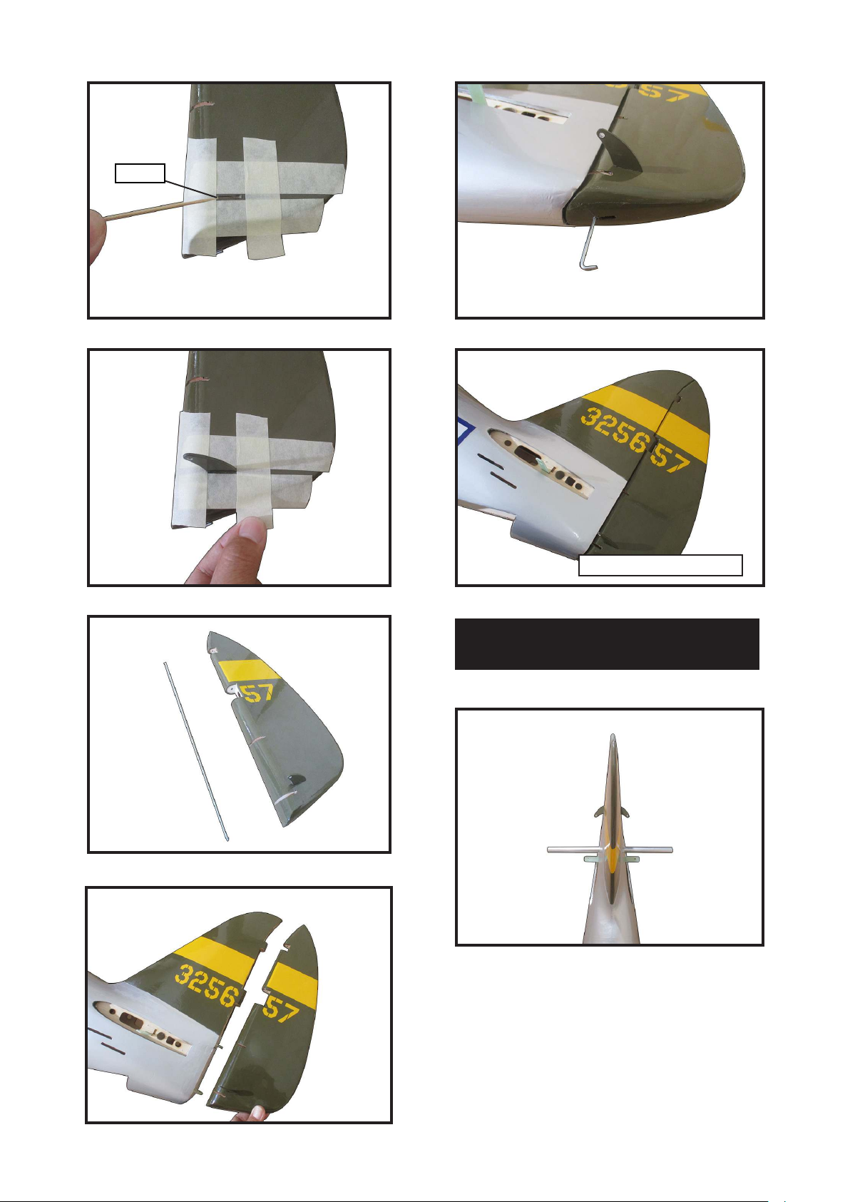
INSTALLING HORIZONTAL
STABLLIZER
1.
9.
Use Epoxy Glue to glue the Horizontal
Stabilizer to the fuselage.
35
Page 36
Giant P-47 55-60cc Gas/EP ARF, 81”
Instruction Manual.
2.
3.
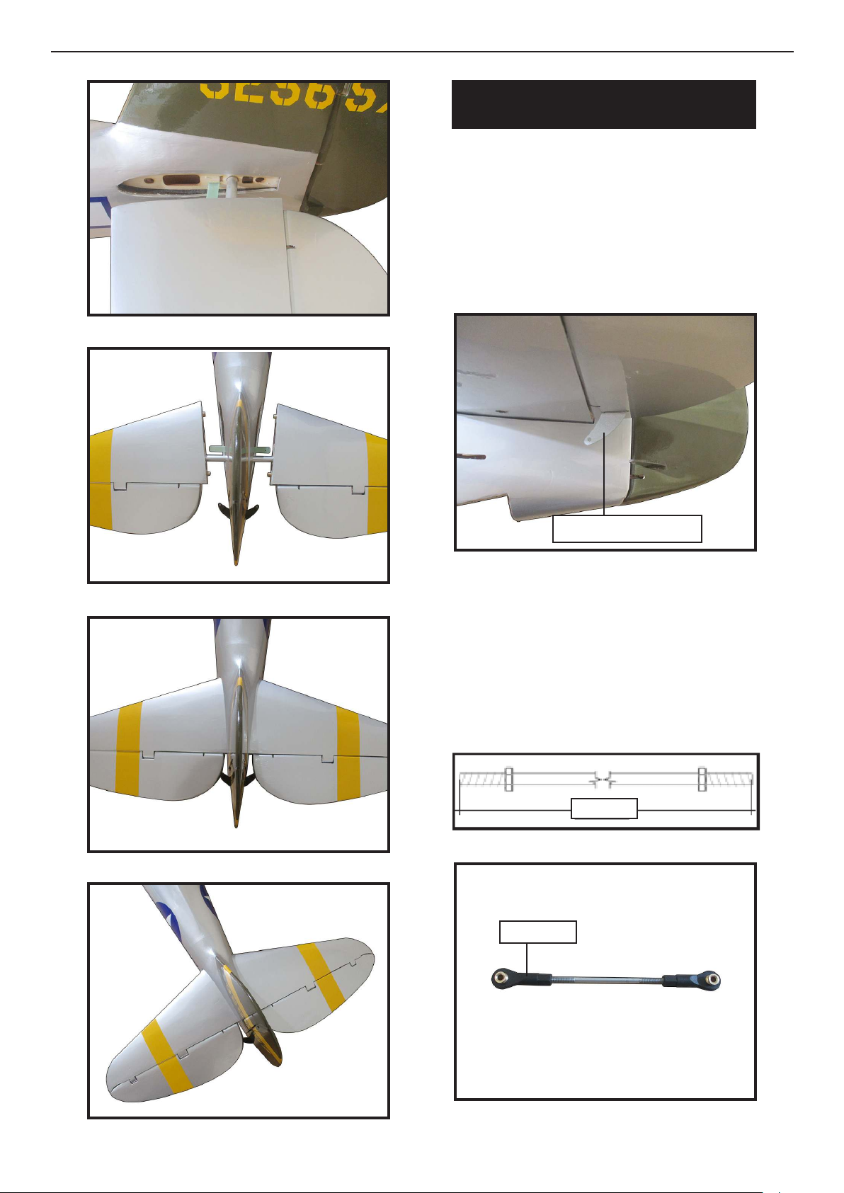
ELEVATOR PUSHROD HORN
INSTALLATION
Install the elevator control horn using the
same method as with the aileron control
horns.
Position the elevator control horn on the
both side of elevator.
1.
4.
5.
Elevator control horn
read one clevis and M3 lock nut on
to each elevator control rod. read the
horns on until they are ush with the
ends of the control rods.
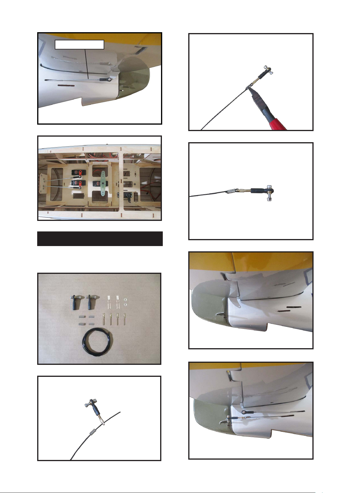
Elevator and rudder pushrods assembly
as pictures below.
2.
870mm
3.
Ball Link
36
Page 37
4.
5.
3.
Elevator pushrod
4.
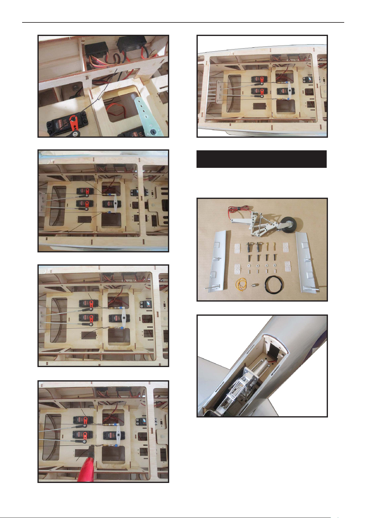
RUDDER PUSHROD INSTALLATION
Repeat steps as same as steps done for elevator.
1.
2.
5.
6.
37
Page 38
Giant P-47 55-60cc Gas/EP ARF, 81”
Instruction Manual.
7.
8.
11.
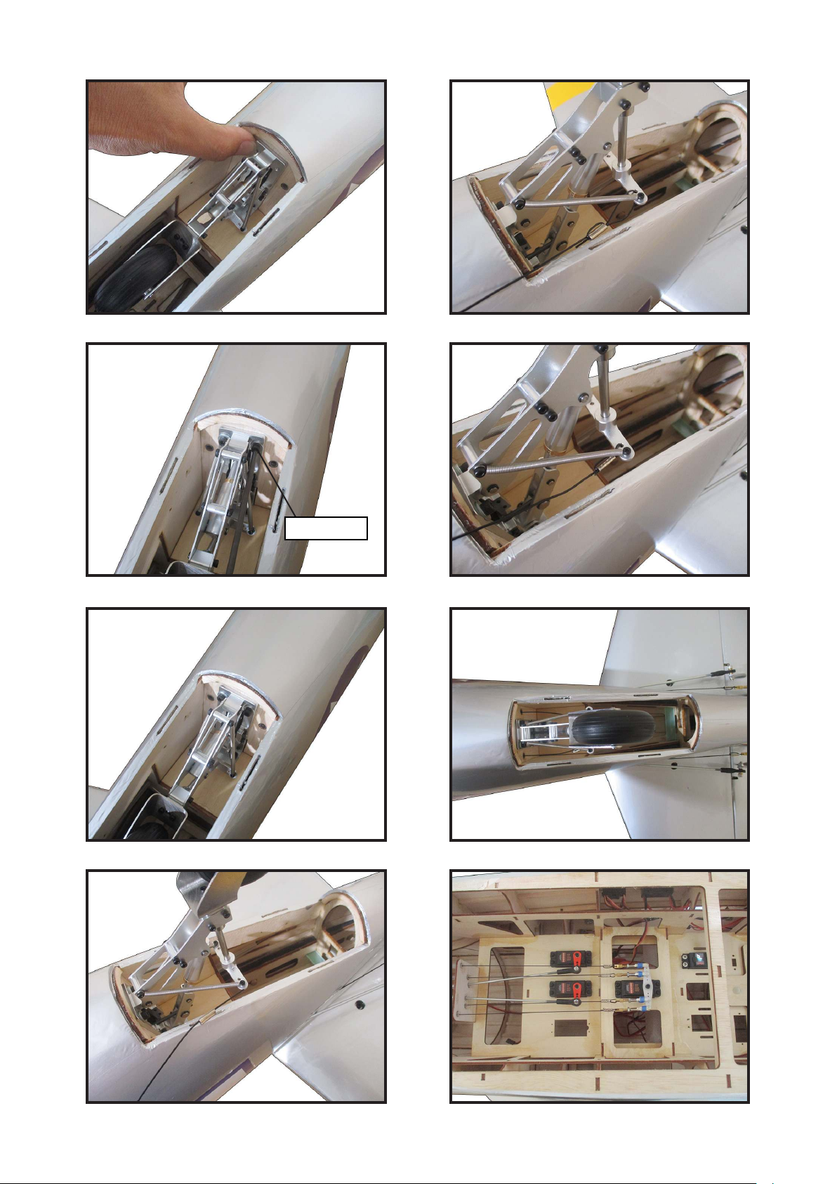
MOUNTING THE TAIL WHEEL
Locate items necessary to intall tail wheel.
1.
9.
10.396.
2.
38
Page 39
3. 7.
4. 8.
M3x15mm
5. 9.
10.
Page 40
Giant P-47 55-60cc Gas/EP ARF, 81”
Instruction Manual.
11.4119. 23.
15.
12. 16.
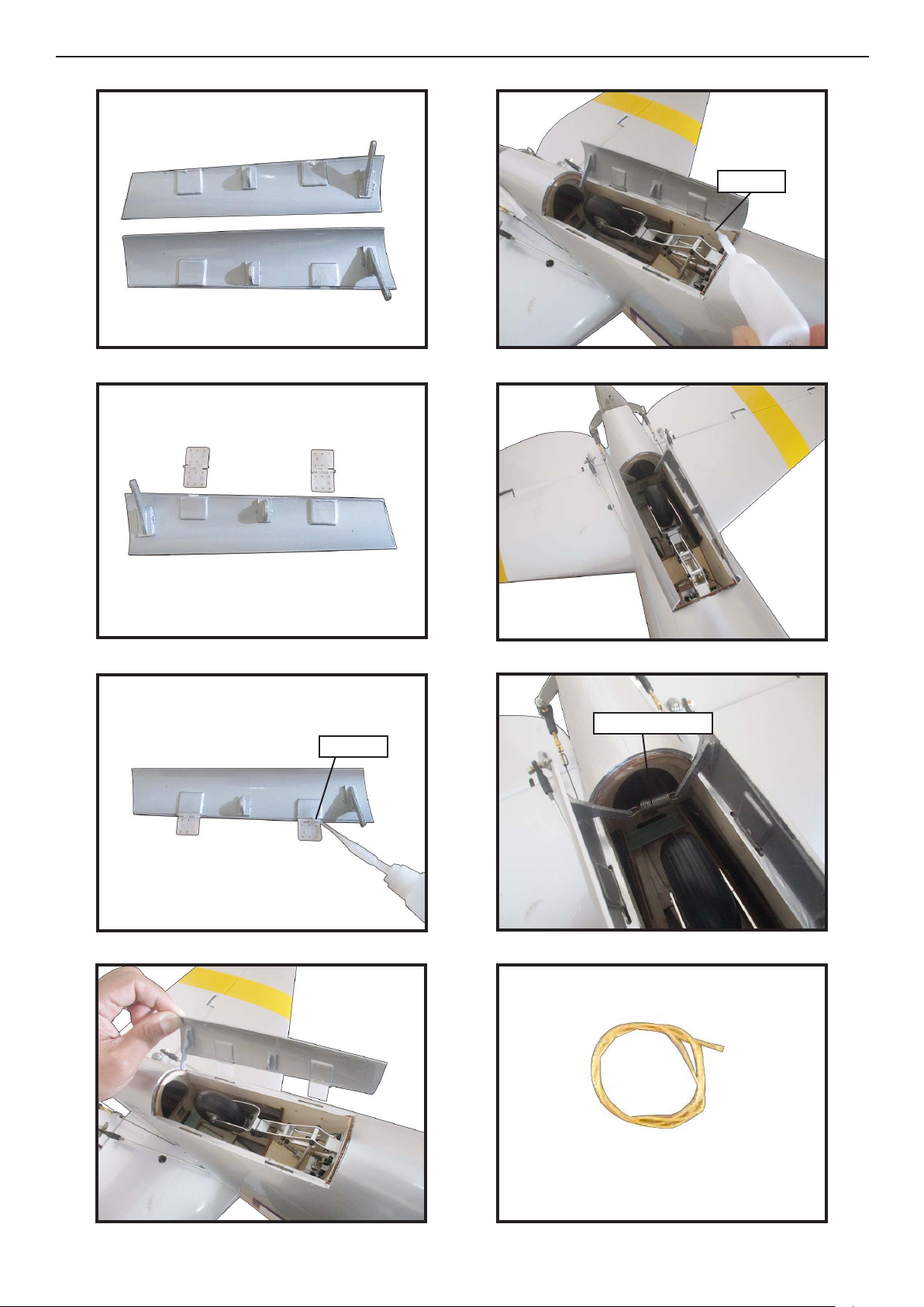
Epoxy
13. 17.
Epoxy
14. 18.
Install springs
40
Page 41
20. 24.
21.
22.
25.
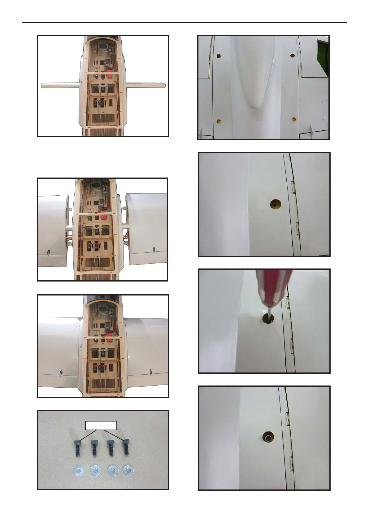
AT TCHMENT WING-FUSELAGE
Attach the aluminium tube into fuselage.
Page 42
Giant P-47 55-60cc Gas/EP ARF, 81”
Instruction Manual.
1.
Insert two lower wing panels as pictures
below..
2.
5.
6.
3.
4 .
7.
8.
4x12mm
42
Page 43
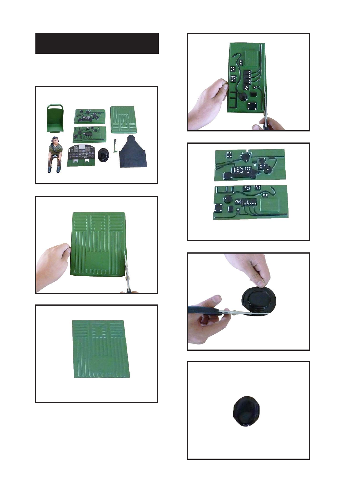
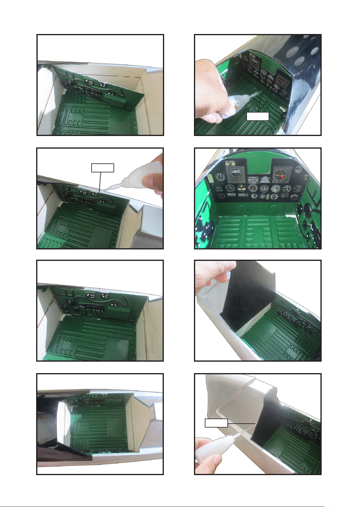
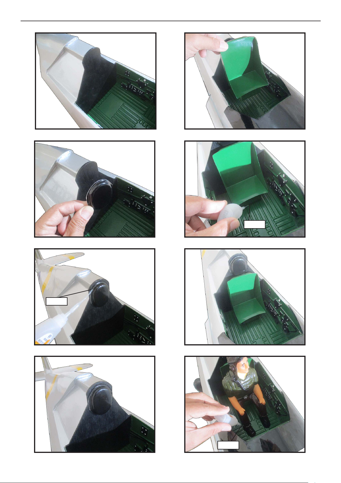
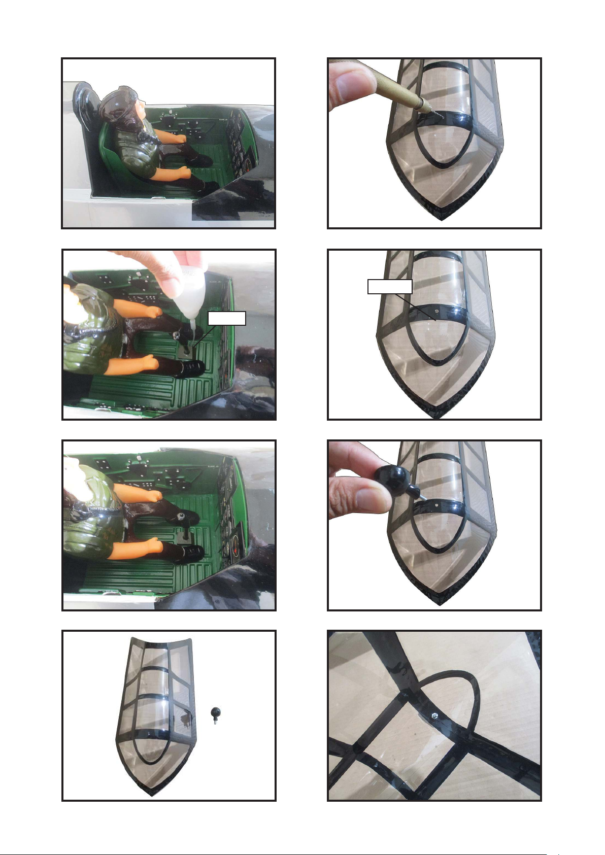
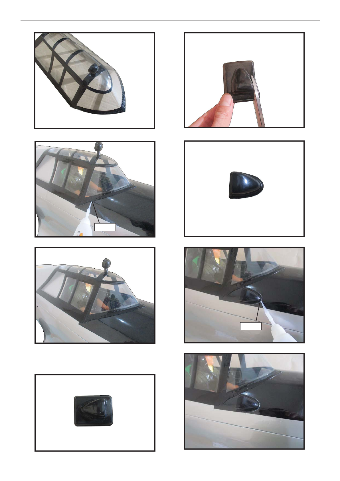
INSTALLATION COCKPIT, PILOT AND
CANOPY
Locate items necessary to install.
1.
2.
4.
5.
3.
6.
7.
43
Page 44
Giant P-47 55-60cc Gas/EP ARF, 81”
Instruction Manual.
8.
9.
12.
13.
10.
11.
14.
Epoxy
15.
Epoxy
44
Page 45
16.
20.
Epoxy
17.
18.
21.
Epoxy
22.
19.
23.
Epoxy
45
Page 46
Giant P-47 55-60cc Gas/EP ARF, 81”
Instruction Manual.
24.
25.
28.
29.
26.
27.
Epoxy
30.
Epoxy
31.
46
Epoxy
Page 47
32.
36.
33.
34.
37.
3.2mm
Epoxy
38.
35.
39.
47
Page 48
Giant P-47 55-60cc Gas/EP ARF, 81”
Instruction Manual.
40.
41.
44.
45.
42.
Install rearview mirror.
43.
Epoxy
46.
Ep ox y.
Epoxy
47.
48
Page 49
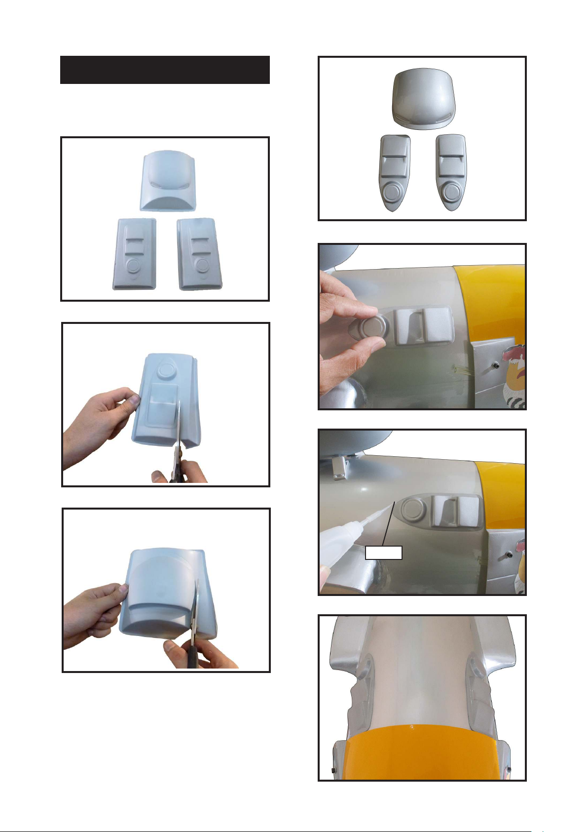
INSTALLING SCALE PARTS
Parts requirement.See pictures below.
1.
2.
4.
5.
3.
6.
Epoxy
7.
49
Page 50
Giant P-47 55-60cc Gas/EP ARF, 81”
Instruction Manual.
8.
9.
1.
3.
10.
Epoxy
4.
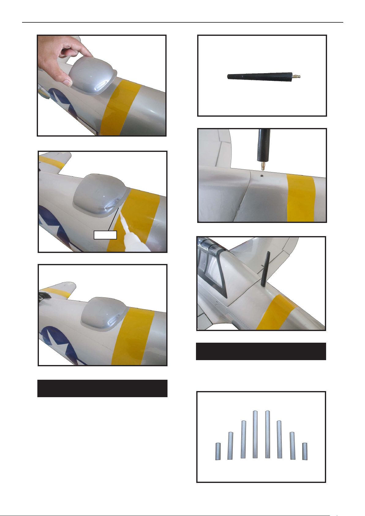
INSTALL THE GUN ON THE WING
Parts requirement.See pictures below.
INSTALLING NEEDED ANTEN
1.
Parts requirement.See pictures below.
50
Page 51
2.
3.
2.
3.
4.
Epoxy
C/A glue
4.
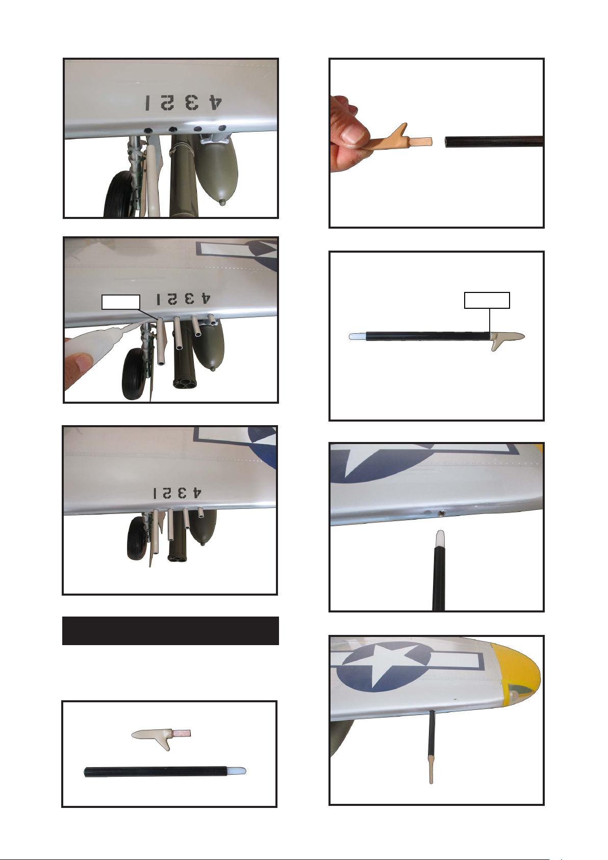
INSTALL PITOT TUBE (PROT WING)
Please study images below.
1.
5.
51
Page 52
Giant P-47 55-60cc Gas/EP ARF, 81”
Instruction Manual.
APPLY THE DECALS
If all the decals are precut and ready to
stick. Please be certain the model is clean
and free from oily ngerprints and dust.
Position decal on the model where desired, using the photos on the box and
aid in their location.
If all the decals are not precut, please use
scissors or a sharp hobby knife to cut the
decals from the sheet. Please be certain
the model is clean and free from oily ngerprints and dust. Position decal on the
model where desired, using the photos
on the box and aid in their location.
BALANCING
*If possible, rst attempt to balance the
model by changing the position of the receiver battery and receiver. If you are unable to obtain good balance by doing so,
then it will be necessary to add weight to
the nose or tail to achieve the
proper balance point.
With the wings attached to the fuselage,
all parts of the model installed ( ready to
y), and empty fuel tanks, hold the model at the marked balance point with the
stabilizer level.
Li the model. If the tail drops when you
li, the model is “tail heavy” and you
must add weight* to the nose. If the nose
drops, it is “nose heavy” and you must
add weight* to the tail to balance.
It is critical that your airplane be
balanced correctly. Improper balance will
cause your plane to lose control and
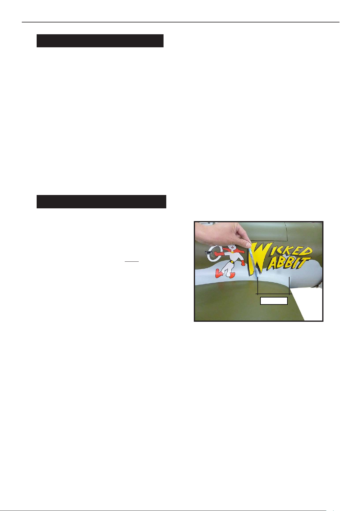
crash. THE CENTER OF GRAVITY IS LOCATED 130MM BACK
FROM THE LEADING EDGE OF
THE WING AT THE WING ROOT.
Mount the wing to the fuselage. Place a
piece of masking tape on the top of each
wing 130mm back from the leading edge
at the wing root.
With the model inverted, place your ngers on the masking tape and carefully
li the plane. is is the point at which
your model should balance for your rst
ights. Later, you may wish to experiment by shiing the balance up to 10mm
forward or back to change the ying
characteristics. Moving the balance forward may improve the smoothness and
arrow- like tracking, but it may then require more speed for take o and make it
more dicult to slow down for landing.
Moving the balance a makes the model
more agile with a lighter and snappier
”feel”. In any case, please start at the location we recommend.
1.
130mm
52
Page 53
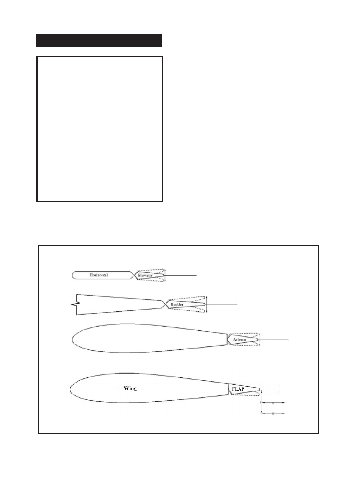
CONTROL THROWS
Ailerons:
High Rate :
Up : 20 mm
Down : 20 mm
Low Rate :
Up : 15 mm
Down : 15 mm
Elevator:
High Rate :
Up : 20 mm
Down : 20 mm
Low Rate :
Up : 15 mm
Down : 15 mm
Rudder:
High Rate :
Right : 25 mm
Le : 25 mm
Low Rate :
Right : 20 mm
Le : 20 mm
Flap:
Mid : 40mm
Full : 40mm
Fuselage
Wing
15-20mm
15-20mm
20-25mm
20-25mm
15-20mm
15-20mm
40mm
40mm
53
Page 54

Giant P-47 55-60cc Gas/EP ARF, 81”
Instruction Manual.
FLIGHT PREPARATION PREFLIGHT CHECK
Check the operation and direction of the
elevator, rudder, ailerons and throttle.
A) Plug in your radio system per the
manufacturer’s instructions and turn everything on.
B) Check the elevator rst. Pull back
on the elevator stick. e elevator halves
should move up. If it they do not, ip the
servo reversing switch on your transmitter to change the direction.
C) Check the rudder. Looking from behind the airplane, move the rudder stick
to the right. e rudder should move
to the right. If it does not, ip the servo
reversing switch on your transmitter to
change the direction.
1) Completely charge your transmitter and receiver batteries before your rst
day of ying.
2) Check every bolt and every glue joint
in the Giant P-47 55-60cc Gas/EP ARF,
81” to ensure that everything is tight and
well bonded.
3) Double check the balance of the airplane. Do this with the fuel tank empty.
4) Check the control surfaces. All
should move in the correct direction and
not bind in any way.
5) If your radio transmitter is equipped
with dual rate switches double check that
they are on the low rate setting for your
rst few ights.
D) Check the throttle. Moving the
throttle stick forward should open the
carburetor barrel. If it does not, ip the
servo reversing switch on your transmitter to change the direction.
E) From behind the airplane, look at the
aileron on the right wing half. Move the
aileron stick to the right. e right aileron should move up and the other aileron
should move down. If it does not, ip the
servo reversing switch on your transmitter to change the direction.
We wish you many safe and enjoyable ights
with your Giant P-47 55-60cc Gas/EP ARF, 81”.
6) Check to ensure the control surfaces are moving the proper amount
for both low and high rate settings.
7) Check the receiver antenna. It should
be fully extended and not coiled up inside the fuselage.
8) Properly balance the propeller. An
out of balance propeller will cause excessive vibration which could lead to engine
and/or airframe failure.
54
Page 55

If you have any queries, or are interested in our products,
please feel free to contact us
Factory : 12/101A - Hamlet 4 - Le Van Khuong Street - Dong anh Ward -
Hoc Mon District - Ho Chi Minh City - Viet Nam.
Oce : 62/8 Ngo Tat To Street - Ward 19 - Binh anh District - Ho Chi Minh
City - Viet Nam
Phone : 848 - 86622289 or 848- 36018777
Website : www.SeagullModels.com
Email : [email protected]
Facebook : www.facebook.com/SeaGullModels.
55
 Loading...