

Page 1
WWW.SEAGULLMODELS.COM
ASSEMBLY MANUAL
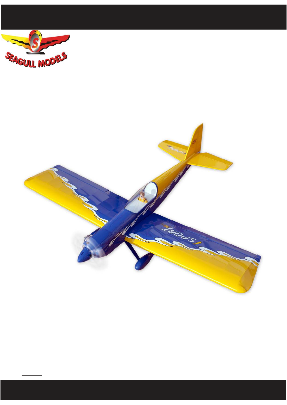
ISPORTS
“ Graphics and specications may change without notice “ .
10cc
ALMOST
READY TO FLY
MS: 210
www.seagullmodels.com
Specications:
Wingspan---------------65.0 in (165 cm).
Wing area----------------821.5 sq.in (53.0 sq.dm).
Weight-------------------7.1 - 7.9 lbs (3.2 - 3.6 kg).
Length-------------------51.9 in (131.7cm).
Engine-------------------0.55 - 0.61 cu.in -2 stroke
...................................10cc - 15cc.
Radio--------------------5 channels with 7 servos.
Electric conversion: Optional.
1
Page 2
ISPORT 10-15cc
INTRODUCTION.
Instruction Manual.
ank you for choosing the ISPORT ARTF by SEAGULL MODELS COMPANY LTD,. e
ISPORT was designed with the intermediate/advanced sport yer in mind. It is a semi scale
airplane which is easy to y and quick to assemble. e airframe is onventionally built using
balsa, plywood to make it stronger than the average ARTF, yet the design allows the aeroplane
to be kept light. You will nd that most of the work has been done for you already. e motor mount has been tted and the hinges are pre-installed. Flying the ISPORT is simply a joy.
is instruction manual is designed to help you build a great ying earoplane. Please read
this manual throughly before starting assembly of your ISPORT. User the parts listing below
to indentify all parts.
WARNING.
Please be awere that this aeroplane is not a toy and if assembley or used incorrectly it is
capable of causing injury to people or property. WHEN YOU FLY THIS AEROPLANE YOU
ASSUME ALL RISK & REPONSIBILITY.
If you are inexperianced with basic R/C ight we strongly recommend you contact your R/C
supplier and join your local R/C model Flying Club. R/C Model Flying Clubs oer a variety
of training procedures designed to help the new pilot on his way to successful R/C ight.
ey will also be able to advise on any insurance and safety regulations that may apply.
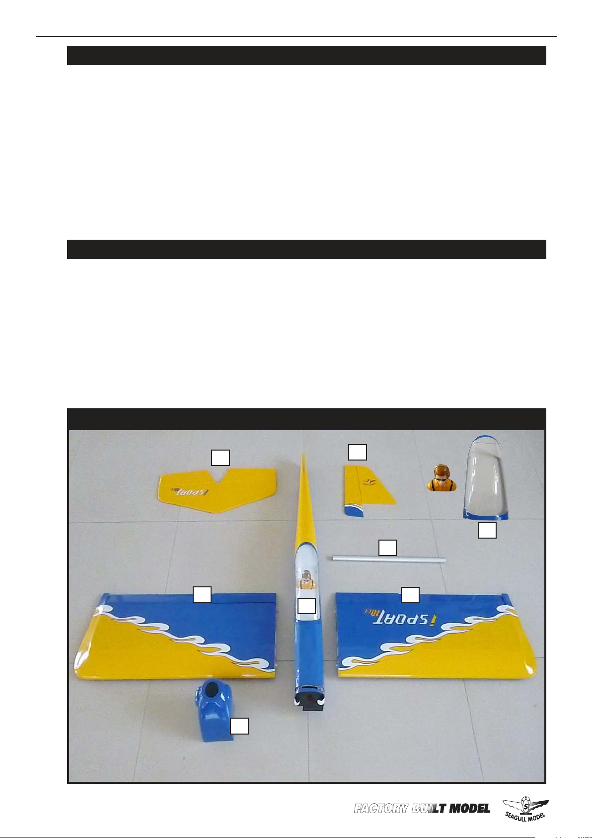
KIT CONTENTS
3
2
1
3
4
10
2
5
2
Page 3
WWW.SEAGULLMODELS.COM
KIT CONTENTS.
SEA2101 Fuselage
SEA2102 Wing set
SEA2103 Tail set
SEA2104 Canopy Hatch
SEA2105 Cowling
SEA2106 Landing gear
SEA2107 Hardware set
SEA2108 Pushrod set
SEA2109 Wheel Pants
SEA2110 Wing tube
ADDITIONAL ITEMS REQUIRED.
HINGING THE AILERONS.
Note : e control surfaces, including the ai-
lerons, elevators, and rudder, are prehinged
with hinges installed, but the hinges are not
glued in place. It is imperative that you properly adhere the hinges in place per the steps
that follow using a high-quality thin C/A glue.
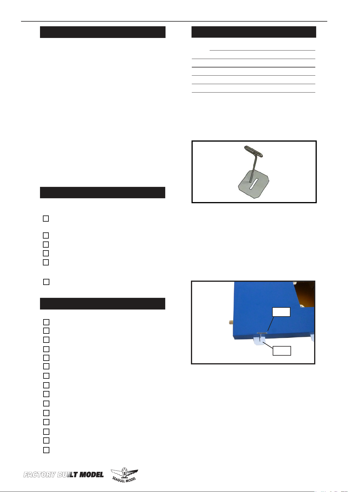
1) Carefully remove the aileron from one
of the wing panels. Note the position of the
hinges.
0.55-0.61 2 stroke.
10cc - 15cc
Computer radio with 5 servos.
Glow plug to suit engine.
Propeller to suit engine.
Protective foam rubber for radio
system.
Silicone fuel line.
TOOLS & SUPPLIES NEEDED.
ick cyanoacrylate glue.
30 minute epoxy.
5 minute epoxy.
Hand or electric drill.
Assorted drill bits.
Modelling knife.
Straight edge ruler.
2mm ball driver.
Phillips head screwdriver.
220 grit sandpaper.
90° square or builder’s triangle.
Wire cutters.
Masking tape & T-pins.
read-lock.
Paper towels.
2) Remove each hinge from the wing panel
and aileron and place a T-pin in the center of
each hinge. Slide each hinge into the aileron
until the T-pin is snug against the aileron.
is will help ensure an equal amount of
hinge is on either side of the hinge line when
the aileron is mounted to the wing panel.
T-pin.
.
Hinge.
3) Slide the aileron on the wing panel until
there is only a slight gap. e hinge is now
centered on the wing panel and aileron. Remove the T-pins and snug the aileron against
the wing panel. A gap of 1/64” or less should
be maintained between the wing panel and
aileron.
3
Page 4
ISPORT 10-15cc
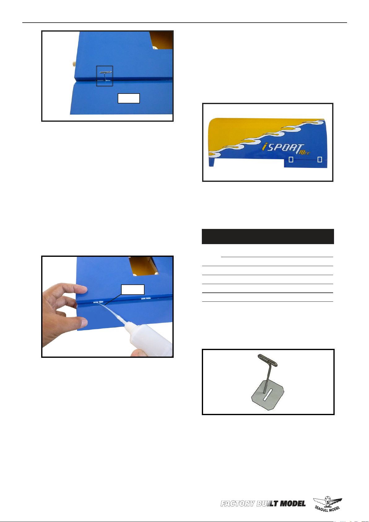
Hinge.
4) Deect the aileron and completely saturate each hinge with thin C/A glue. e ailerons front surface should lightly contact the
wing during this procedure. Ideally, when
the hinges are glued in place, a 1/64” gap or
less will be maintained throughout the lengh
of the aileron to the wing panel hinge line.
NOTE : e hinge is constructed of a special material that allows the C/A to wick
or penetrate and distribute throughout
the hinge, securely bonding it to the wood
structure of the wing panel and aileron.
Instruction Manual.
8) Aer both ailerons are securely hinged,
rmly grasp the wing panel and aileron to
make sure the hinges are securely glued and
cannot be pulled out. Do this by carefully applying medium pressure, trying to separate
the aileron from the wing panel. Use caution
not to crush the wing structure.
Note :
Work the aileron up and down several times to “work in” the hinges
and check for proper movement.
HINGING THE AILERONS.
Ep ox y.
5) Turn the wing panel over and deect the
aileron in the opposite direction from the
opposite side. Apply thin C/A glue to each
hinge, making sure that the C/A penetrates
into both the aileron and wing panel.
6) Using C/A remover/debonder and a paper towel, remove any excess C/A glue that
may have accumulated on the wing or in the
aileron hinge area.
7) Repeat this process with the other wing
panel, securely hinging the aileron in place.
Note : e control surfaces, including the ailerons, elevators, and rudder, are prehinged
with hinges installed, but the hinges are not
glued in place. It is imperative that you properly adhere the hinges in place per the steps
that follow using a high-quality thin C/A glue.
1) Carefully remove the aileron from one
of the wing panels. Note the position of the
hinges.
2) Remove each hinge from the wing panel
and aileron and place a T-pin in the center of
each hinge. Slide each hinge into the aileron
until the T-pin is snug against the aileron.
is will help ensure an equal amount of
hinge is on either side of the hinge line when
the aileron is mounted to the wing panel.
4
Page 5
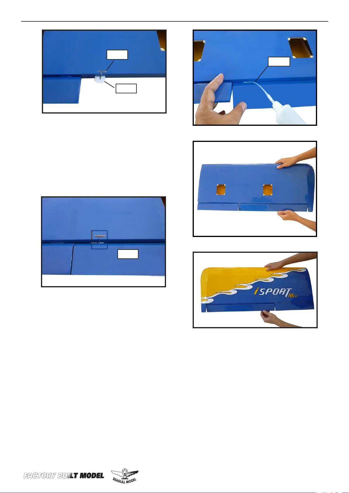
WWW.SEAGULLMODELS.COM
T-pin.
Hinge.
.
3) Slide the aileron on the wing panel until
there is only a slight gap. e hinge is now
centered on the wing panel and aileron. Remove the T-pins and snug the aileron against
the wing panel. A gap of 1/64” or less should
be maintained between the wing panel and
aileron.
Ep ox y.
Hinge.
4) Deect the aileron and completely saturate each hinge with thin C/A glue. e ailerons front surface should lightly contact the
wing during this procedure. Ideally, when
the hinges are glued in place, a 1/64” gap or
less will be maintained throughout the lengh
of the aileron to the wing panel hinge line.
NOTE : e hinge is constructed of a special material that allows the C/A to wick
or penetrate and distribute throughout
the hinge, securely bonding it to the wood
structure of the wing panel and aileron.
5) Turn the wing panel over and deect the
aileron in the opposite direction from the
opposite side. Apply thin C/A glue to each
hinge, making sure that the C/A penetrates
into both the aileron and wing panel.
6) Using C/A remover/debonder and a paper towel, remove any excess C/A glue that
may have accumulated on the wing or in the
aileron hinge area.
7) Repeat this process with the other wing
panel, securely hinging the aileron in place.
5
Page 6
ISPORT 10-15cc
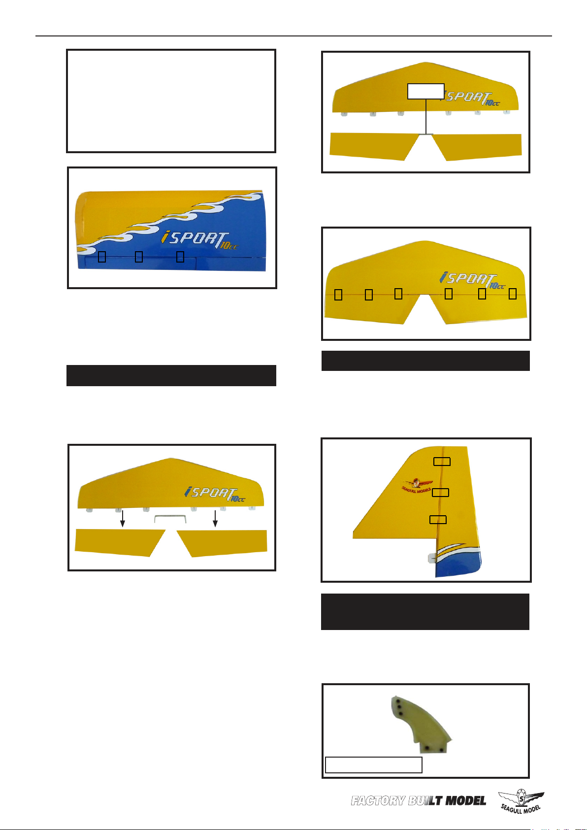
8) Aer both ailerons are securely hinged,
rmly grasp the wing panel and aileron to
make sure the hinges are securely glued and
cannot be pulled out. Do this by carefully
applying medium pressure, trying to separate
the aileron from the wing panel. Use caution
Instruction Manual.
Ep ox y.
Glue the hinge hinges in place using the
same techniques used to hing the ailerons.
Note :
Work the aileron up and down several times to “work in” the hinges
and check for proper movement.
HINGING THE ELEVATORS.
1) Locate the item for this sectiom of the
manual.
2) Carefully remove the elevator from
one of the horizontal stabilizer panels.
Note the position of the hinges.
HINGING THE RUDDER.
Glue the rudder hinges in place using
the same techniques used to hinge the ailerons.
INSTALL THE AILERONS CONTROL
HORN.
3) Remove each hinge from the horizontal stabilizer panel and elevator
Locate the hardware necessary to install
the control horns for the ailerons.
and place a T-pin in the center of each
hinge. Slide each hinge into the elevator until the T-pi n is snug against the
elevator. is will help ensure an equal
amount of hinge is on either side of the
hinge line when the elevator is mounted to the horizontal stabilizer panel.
6
Aileron control horn.
Page 7
WWW.SEAGULLMODELS.COM
Ep ox y.
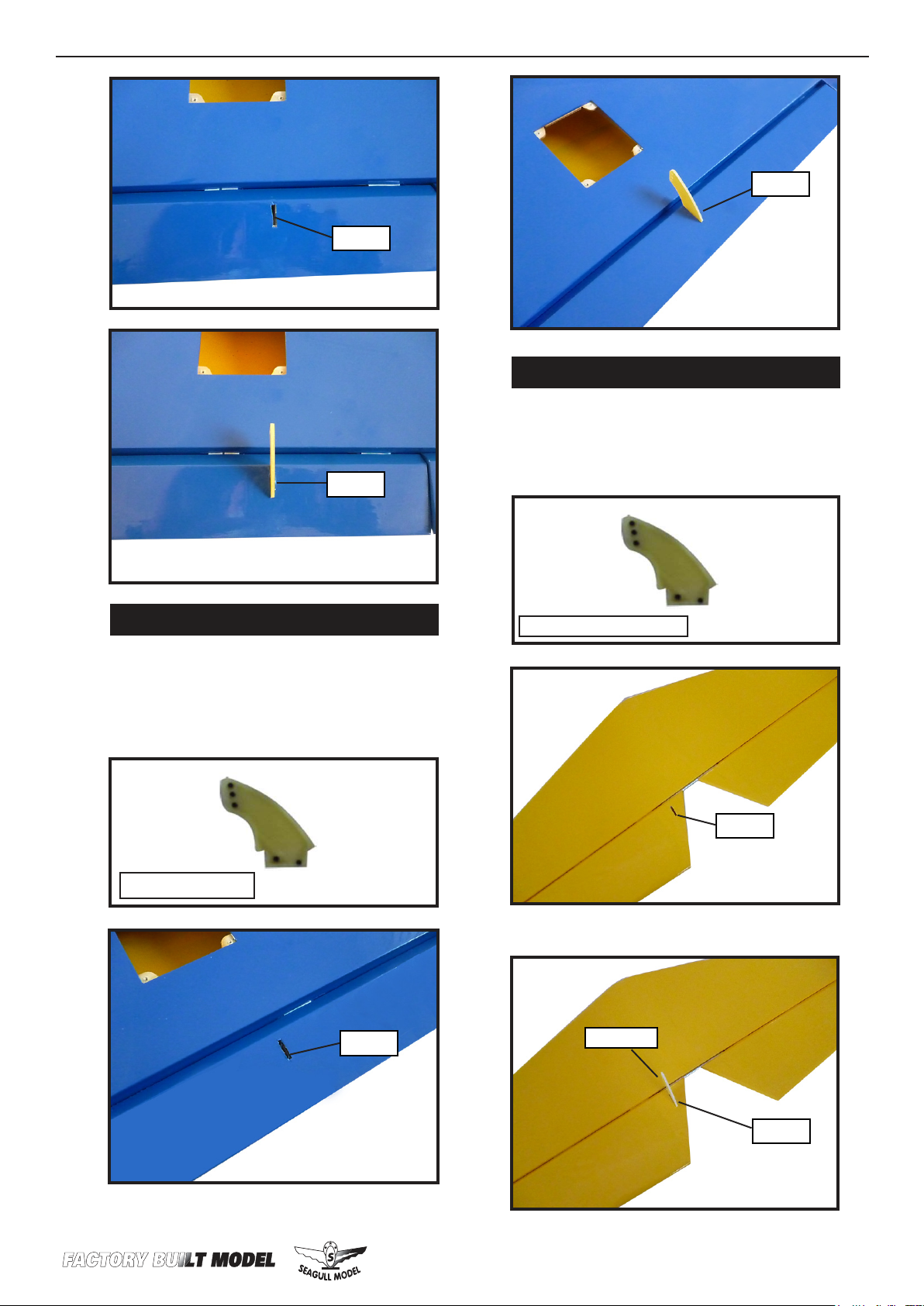
INSTALL ELEVATOR CONTROL HORN.
Install the elevator control horn using
the same method as same as the aileron
control horns.
Ep ox y.
Ep ox y.
INSTALL FLAP CONTROL HORN.
Install the ap control horn using the
same method as same as the aileron control horns.
Flap control horn.
Ep ox y.
Elevator control horn.
Elevator.
.
Ep ox y.
Ep ox y.
7
Page 8
ISPORT 10-15cc
Instruction Manual.
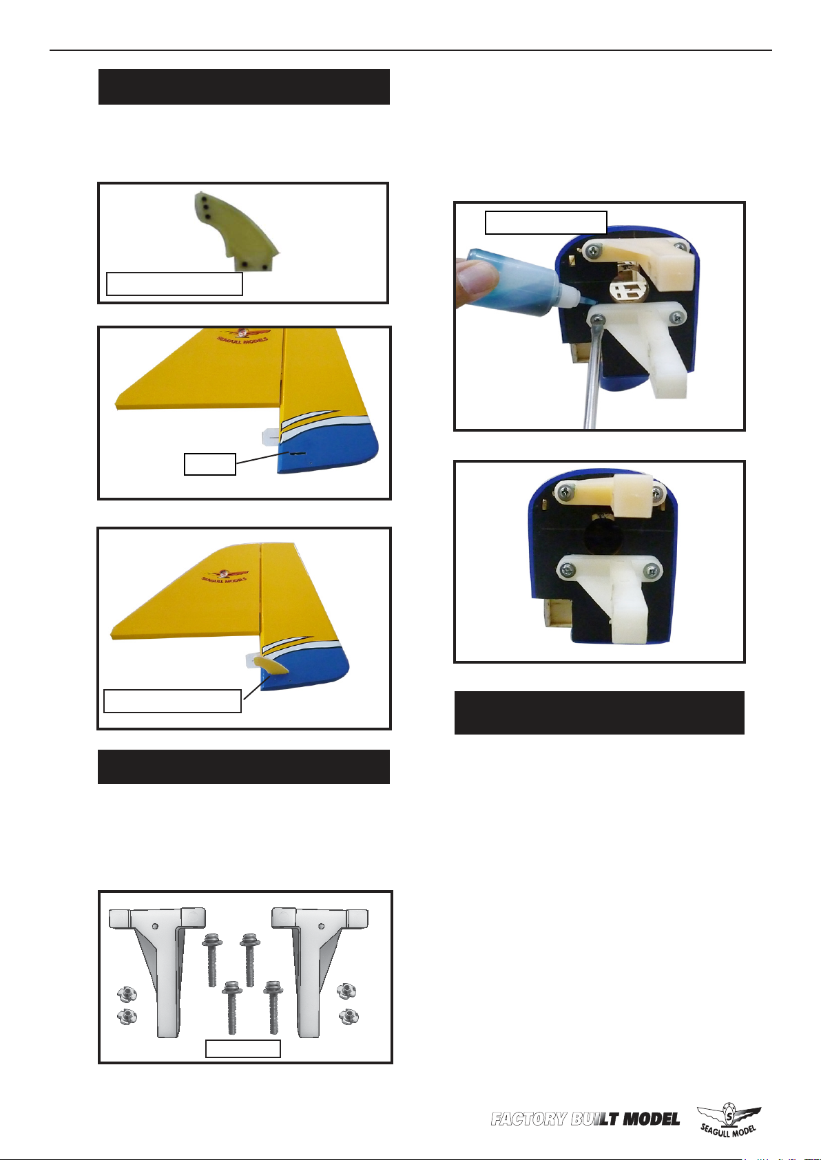
INSTALL RUDDER CONTROL HORN.
Repeat steps to install the rudder control
horn as same as steps done for ailerons.
Rudder control horn.
Ep ox y.
2) Use four 4x30mm head bolts and four
4mm washers to attach the engine mount
rails to the rewall. Tighten the screws .
Make sure to use threadlock on the screws to
help prevent them from vibrating loose.
.
read locker glue.
Rudder control horn.
ENGINE MOUNT INSTALLATION.
1) Locate the items necessary to install
the engine mount included with your
model.
M4x30mm
INSTALLING THE STOPPER
ASSEMBLY.
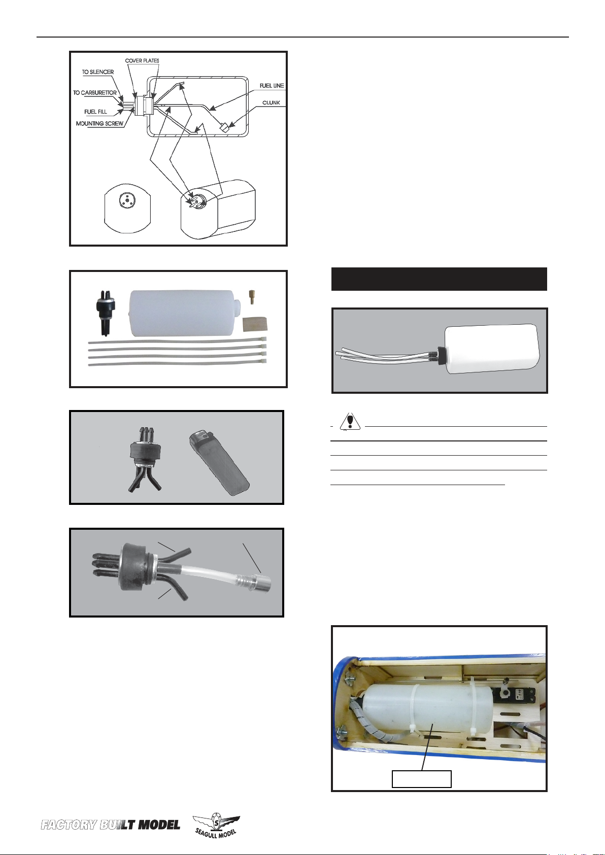
1) Using a modeling knife, carefully cut
o the rear portion of one of the 3 nylon
tubes leaving 1/2” protruding from the
rear of the stopper. is will be the fuel
pick up tube.
2) Using a modeling knife, cut one length
of silicon fuel line. Connect one end of
the line to the weighted fuel pick up and
the other end to the nylon pick up tube.
8
Page 9
WWW.SEAGULLMODELS.COM
5) With the stopper assembly in place, the
weighted pick-up should rest away from the
rear of the tank and move freely inside the
tank. e top of the vent tube should rest just
below the top of the tank. It should not touch
the top of the tank.
6) When satised with the alignment of the
stopper assembly tighten the 3 x 20mm machine screw until the rubber stopper expands
and seals the tank opening. Do not overtighten the assembly as this could cause the
tank to split.
FUEL TANK INSTALLATION.
Vent tube.
Fuel fill tube.
Fuel pick up tube.
3) Carefully bend the second nylon tube up
at a 45º angle. is tube is the vent tube.
4) Test t the stopper assembly into the tank.
It may be necessary to remove some of the
ashing around the tank opening using a
modeling knife. If ashing is present, make
sure none falls into the tank.
You should mark which tube is the vent
and which is the fuel pickup when you attach
fuel tubing to the tubes in the stopper. Once the
tank is installed inside the fuselage, it may be
dicult to determine which is which.
7) Slide the fuel tank into the fuselage. Guide
the lines from the tank through the hole in
the rewall.
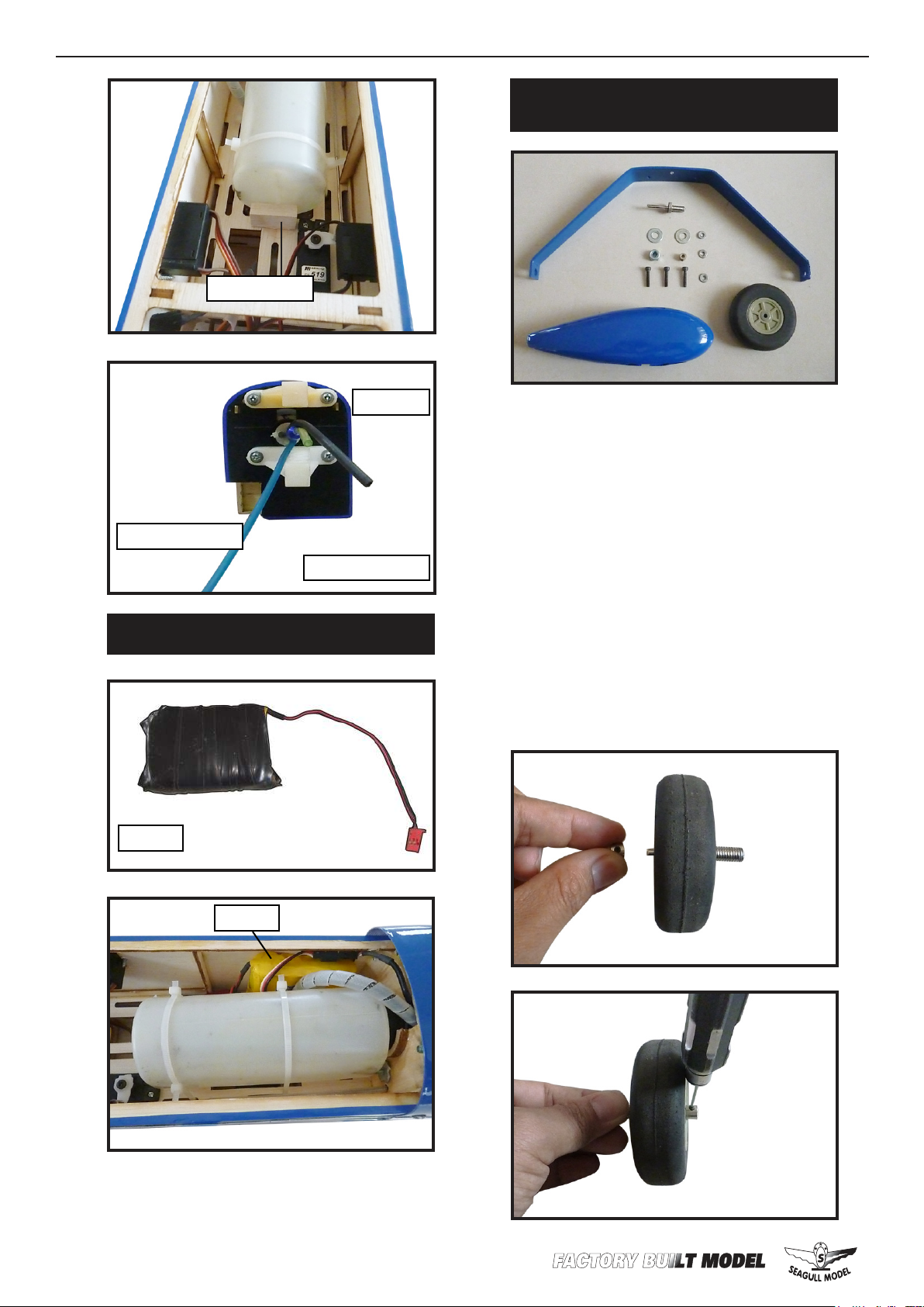
8) Use balsa plywood to help prevent moveable from transferring to the fuel tank as
shown.
Fuel tank.
9
Page 10
ISPORT 10-15cc
Balsa block.
Instruction Manual.
INSTALLING THE MAIN LANDING
GEAR TO FUSELAGE.
Fuel pick up tube.
INSTALLING THE BATTERY.
Batt er y.
Vent tube.
Fuel ll tube.
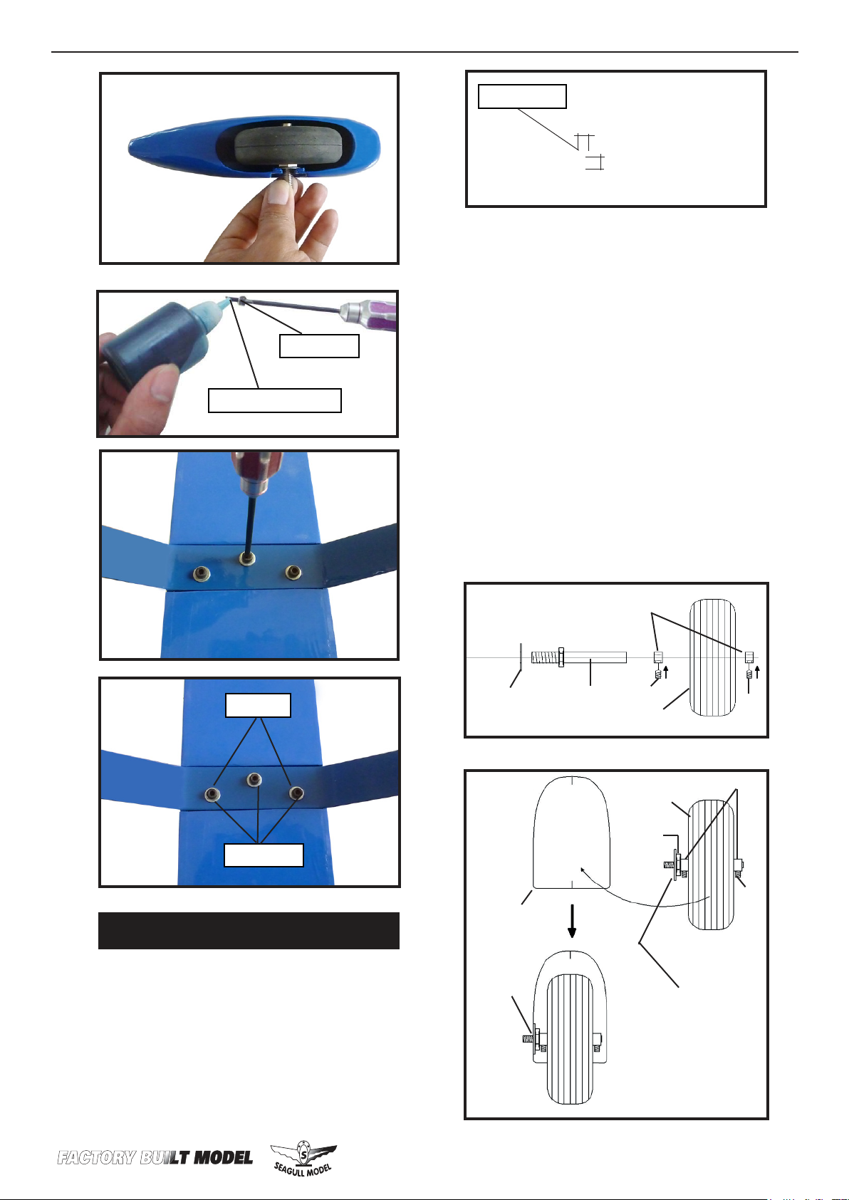
1) e blind nuts for securing the landing gear are already mounted inside the
fuselage.
2) Using the hardware provided, mount
the main landing gear to the fuselage.
3) Place the fuselage inverted on the
workbench in a suitable stand. Set the
landing gear in place and use a screwdrive to secure the landing gear to the fuselage using bolts M4x20mm and washers. Make sure to use the threadlock on
the bolts so they don’t vibrate loose.
10
Batt er y.
Page 11
WWW.SEAGULLMODELS.COM
M4x20mm
read locker glue.
Drill a hole.
8mm.
14mm.
3) You have to trim each axle using a tool
cutting and cut-o wheel.
4) Slide the collar to the axle and setscrew
the collars to secure the collar to the axle
and then slider the wheel on the axle with
a drop of oil on the axle so the wheel will
spin freely when installed. Prepare a second collar and tighten the setscrew using
hex wrench to secure the collar to the
axle.
C/A glue.
M4x20mm
WHEELS AND WHEEL PANTS.
5) Place the wheel assembly in the wheel
pants. e threaded portion of the axle
will t the notch of the wheel pant as
shown.
Wheel collar.
Washer.
Wheel Pant.
Axle.
M3
Wheel.
Wheel.
Washer.
nut.--
M3
Wheel collar.
Axle.
M3.
1) Locate the items neccessary to install
2) Follow diagram below for wheel pant
installation:
Use a drill and 8mm drill bit to drill a
hole in the wheel pants.
C/A glue.
Lite-Plywood
block.
11
Page 12
ISPORT 10-15cc
Instruction Manual.
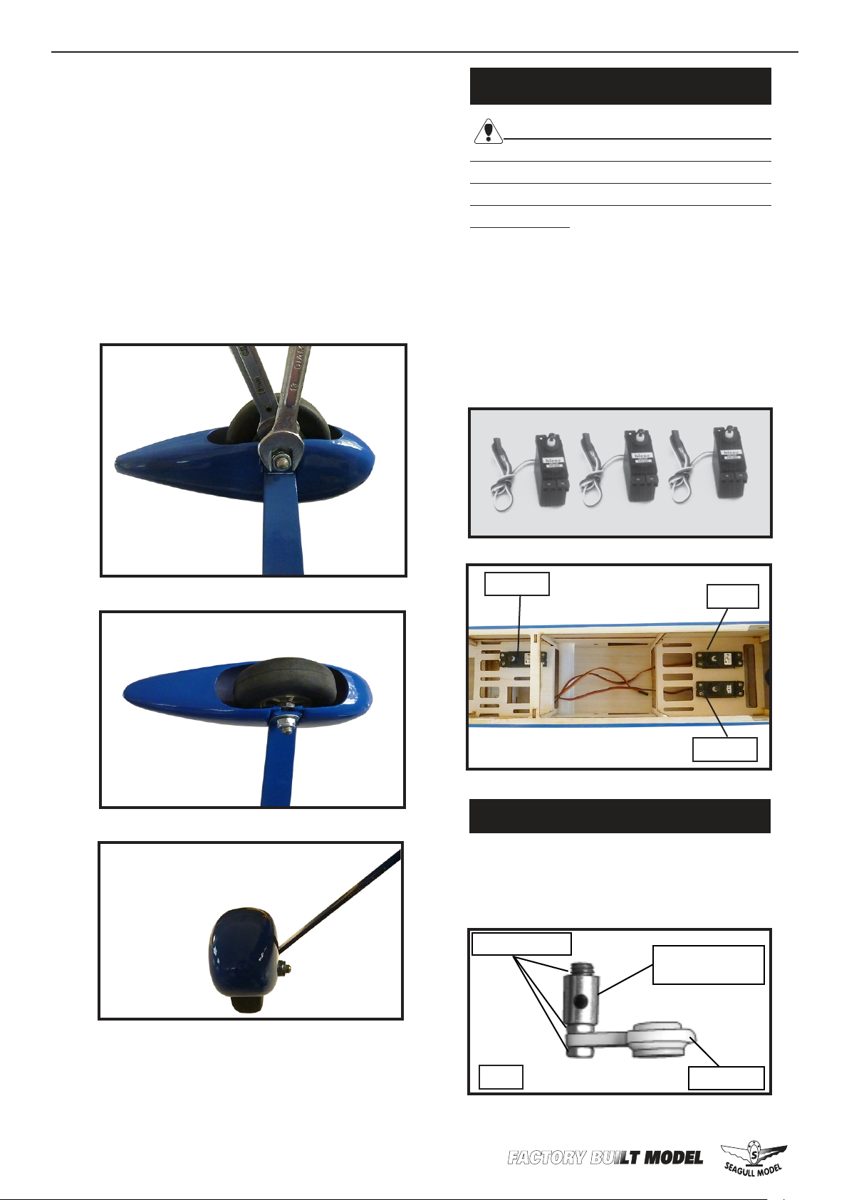
6) Slide the threaded end of the axle
through the hole in the bottom of the
landing gear leg. Use a washer and locknut to tighten the axle to the landing gear.
Make sure to use threadlock on the nut so
it won’t vibrate loose in ight as shown.
7) Tighten the setcrews using a hex
wrench to secure the collars on the axle
over the at spot to retain the wheel as
shown.
INSTALLING THE FUSELAGE SERVOS.
Because the size of servos dier, you
may need to adjust the size of the precut
opening in the mount. e notch in the
sides of the mount allow the servo lead to
pass through.
1) Install the rubber grommets and brass
collets onto the throttle servo. Test t the
servo into the aileron servo mount.
2) Secure the servos with the screws provided with your radio system.
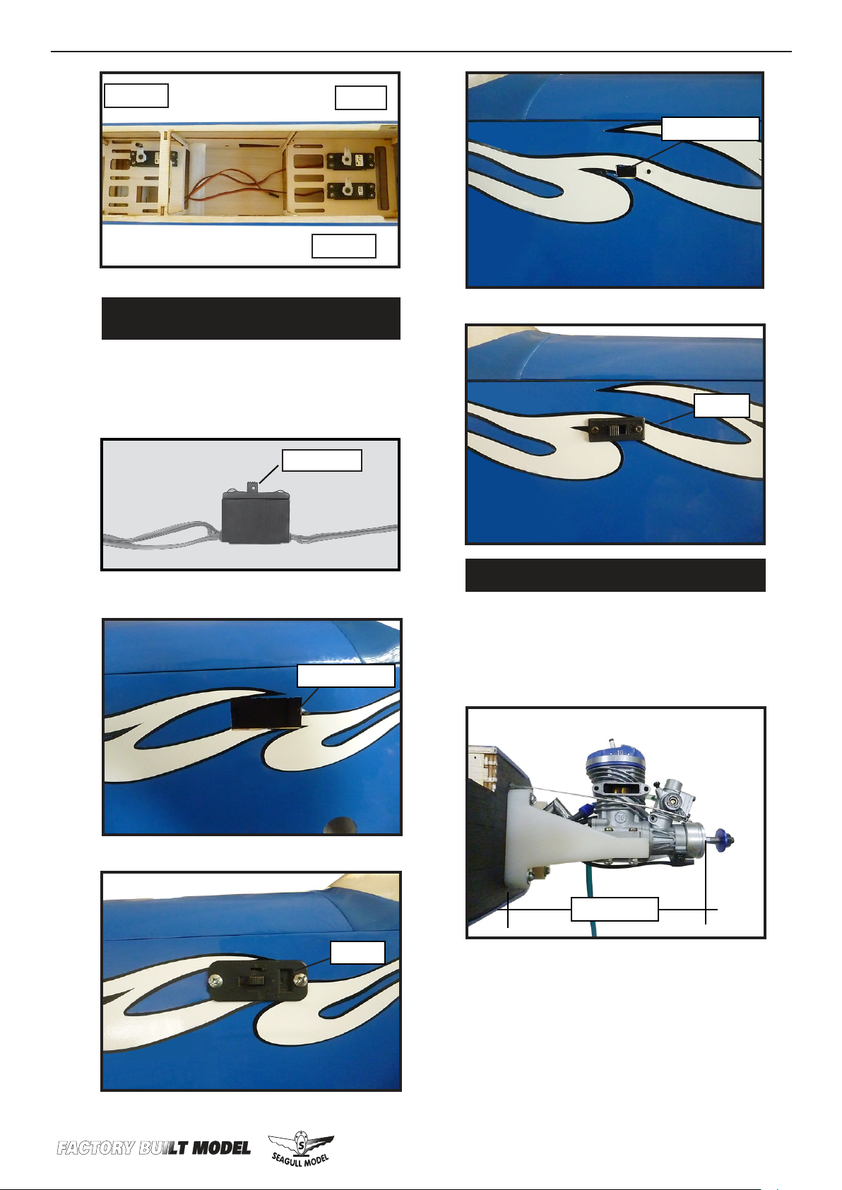
.
rottle.
THROTTLE SERVO ARM INSTALLATION.
Rudder.
Elevator.
Install adjustable servo connector in the
servo arm as same as picture below:
Loctite secure.
Adjustable servo
connector.
12
Repeat steps as above to attach remaining wheel pants to the landing gear.
1PCS.
Servo arm.
Page 13
WWW.SEAGULLMODELS.COM
rottle.
INSTALLING THE SWITCH RECEIVER.
Rudder.
Elevator.
Install the switch into the precut hole in
the side, in the fuselage.
3/32” Hole.
Trim and cut.
Switch.
Trim and cut.
Switch.
MOUNTING THE ENGINE.
1) Position the engine with the drive
washer (110mm) forward of the rewall
as shown.
110 mm
2) Use a pin drill and 2mm drill bit to
drill a small indentation in the mount for
the engine mounting screw.
13
Page 14

ISPORT 10-15cc
2mm
3) Use a drill to drill the four holes in the
engine mount rails.
Instruction Manual.
7) Slide the throttle pushrod wire into
the tube. Position the engine between the
mounts. Use four M4x30mm machine
screws to secure the engine to the mount
as shown.
Machine screw M4x30mm
2mm
2mm
4) On the re wall has the location for the
throttle pusshrod tube (pre-drill).
5) Slide the pushrod tube in the rewall
and guide it through the fuel tank mount.
Use medium C/A to glue the tube to the
rewall and the fuel tank mount.
Pushrod wire.
8) Reinstall the servo horn by sliding the
connector over the pushrod wire. Center
the throttle stick and trim and install the
servo horn perpendicular to the servo
center line.
9) Move the throttle stick to the closed position and move the carburetor to closed.
Use a 2.5mm hex wrench to tighten the
screw that secures the throttle pushrod
wire. Make sure to use threadlock on the
screw so it does not vibrate loose.
14
6) Connect the Z-bend in the 450mm
throttle pushrod to the outer hole of the
carburetor arm.
Page 15
WWW.SEAGULLMODELS.COM
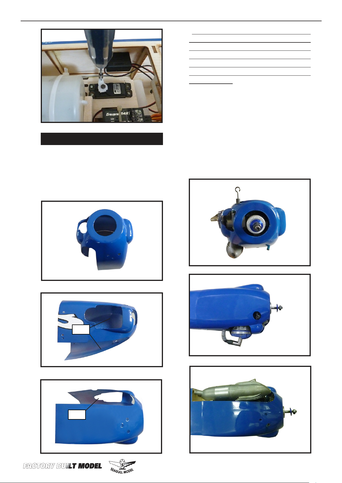
COWLING.
1) Slide the berglass cowl over the engine and line up the back edge of the cowl
with the marks you made on the fuselage
then trim and cut as shown.
Because of the size of the cowl, it may be necessary to use a needle valve extension for the
high speed needle valve. Make this out of sufcient length 1.5mm wire and install it into
the end of the needle valve. Secure the wire in
place by tightening the set screw in the side of
the needle valve.
2) While keeping the back edge of the
cowl ush with the marks, align the front
of the cowl with the cranksha of the
engine. e front of the cowl should be
positioned so the cranksha is in nearly the middle of the cowl opening. Use
the spinner backplate as a guide. Hold
the cowl rmly in place using pieces of
masking tape.
Cut.
Cut.
15
Page 16
ISPORT 10-15cc
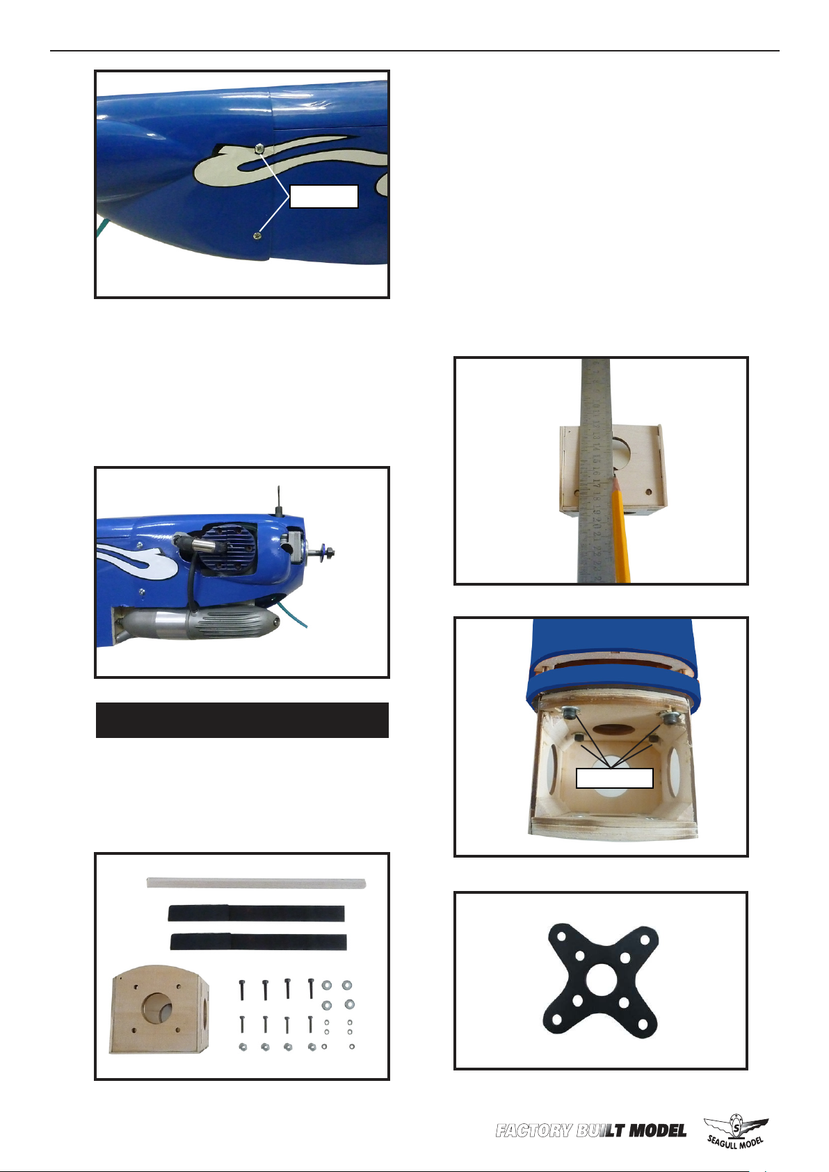
3x10mm
3) Install the muer and muer extension
onto the engine and make the cutout in the
cowl for muer clearance. Connect the fuel
and pressure lines to the carburetor, muer
and fuel ller valve. Secure the cowl to fuselage using the M3x10mm screws.
Instruction Manual.
- Model size: .46-.52 size models
- Motor: 35mm 830 rev per volt
- Propeller: 12x6 ~ 13x6
- ESC: 60A
- Lipo Batteries: 4 cell 4200mA
2) Attach the electric motor box to the
rewall suitable with the cross lines
drawn on the electric motor box and rewall. Using M4x20mm to secure the motor box to the rewall. Please see pictures
be low.
ELECTRIC POWER CONVERSION.
1) Locate the items neccessary to install
the electric power conversion included
with your model.
M4x20mm
16
Page 17
WWW.SEAGULLMODELS.COM
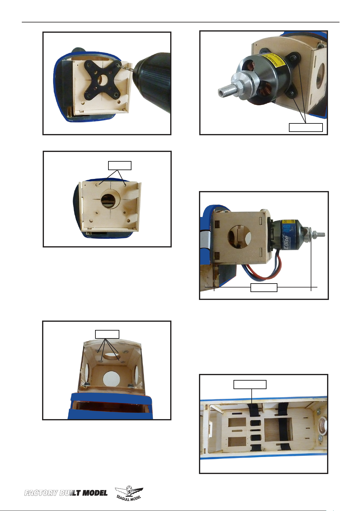
4) Locate the plywood battery tray to the
fuselage. Tighten the screws using machine
4mm.
screws M3x15mm to secure the tray in
position.
M3x15mm
3) Attach the motor to the front of the
electric motor box using four 4mm blind
nut, four M3x15mm hex head bolts to secure the motor. Please see picture shown.
Nut M3.
110 mm
5) Attach the speed control to the side
of the motor box using two-sided tape
and tie wraps. Connect the appropriate
leads from the speed control to the motor. Make sure the leads will not interfere
with the operation of the motor.
Tie wraps.
17
Page 18
ISPORT 10-15cc
Speed control.
Batt er y.
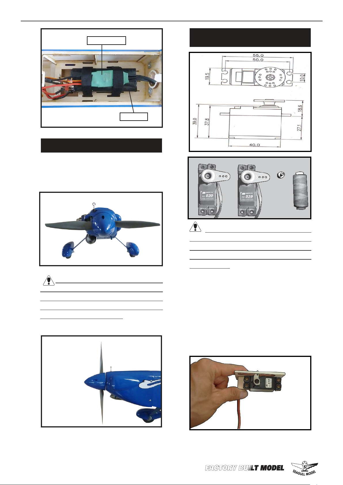
INSTALLING THE SPINNER.
Instruction Manual.
INSTALLING THE AILERON -FLAP
SERVOS.
Install the spinner backplate, propeller
and spinner cone.
e propeller should not touch any
part of the spinner cone. If it does, use a
sharp modeling knife and carefully trim
away the spinner cone where the propeller comes in contact with it.
Servos
.
Small
weight
.
Thread
Because the size of servos dier, you
may need to adjust the size of the precut
opening in the mount. e notch in the
sides of the mount allow the servo lead to
pass through.
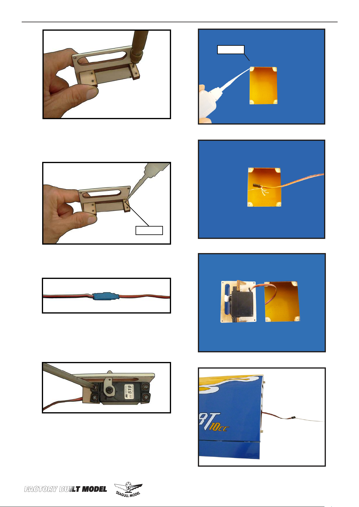
1) Using a small weight (Weighted fuel
pick-up works well) and string, feed the
string through the wing as indicated.
2) Place the servo between the mounting blocks and space it from the hatch.
Use a pencil to mark the mounting hole
locations on the blocks.
.
18
3) Use drill bit in a pin vise to drill the
mouting holes in the blocks.
Page 19
WWW.SEAGULLMODELS.COM
4) Apply 2-3 drops of thin C/A to each
of the mounting holes. Allow the C/A to
cure without using accelerator.
C/A glue
C/A glue
5) Use dental oss to secure the connection so they cannot become unplugged.
6) Secure the servo to the aileron hatch
using Phillips screwdriver and the screws
provided with the servo.
7) Apply 1-2 drops of thin C/A to each of
the mounting tabs. Allow the C/A to cure
without using accelerator.
19
Page 20
ISPORT 10-15cc
2x10mm
Instruction Manual.
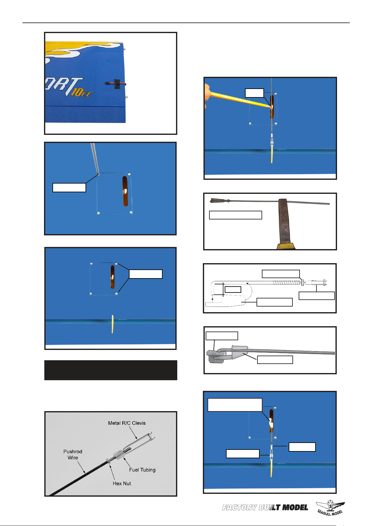
Use a felt tip pen to mark the wire where
it crosses the hole. Use a pair of pliers to
put a shrp 90-degree bend in the wire at
the mark.
Mark.
AILERON PUSHROD HORN
INSTALLATION.
Please see below pictures.
2x10mm
Bend at the mark
M2 lock nut.
8mm
Metal clevis.
Snap keeper.
Servo arm.
Snap keeper.
20
Nylon Snap keeper.
Hex Nut.
Fuel tubing.
Page 21
WWW.SEAGULLMODELS.COM
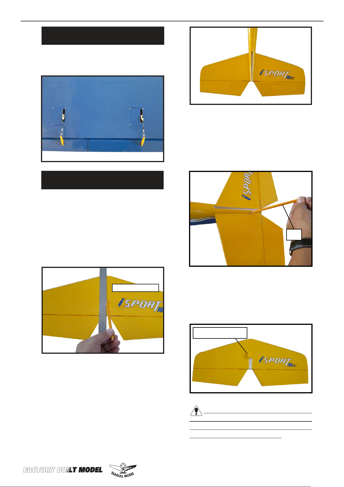
FLAP PUSHROD HORN
INSTALLATION.
Assemble and install the ap pushrods
as same as the aileron pushrod.
INSTALLING THE HORIZONTAL
STABILIZER.
4) With the stabilizer held rmly in place,
use a pen and draw lines onto the stabilizer where it and the fuselage sides meet.
Do this on both the right and le sides
and top and bottom of the stabilizer.
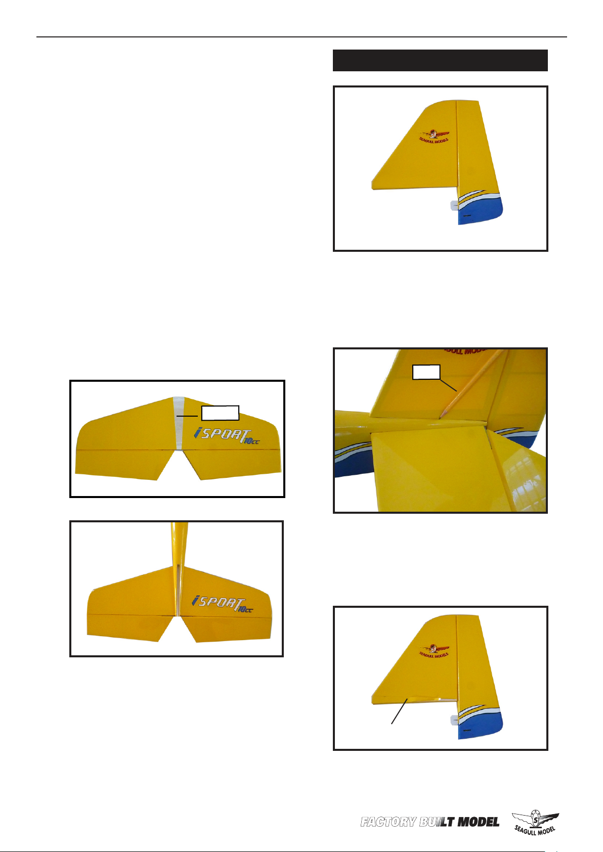
1) Using a ruler and a pen, locate the centerline of the horizontal stabilizer, at the
trailing edge, and place a mark. Use a triangle and extend this mark, from back to
front, across the top of the stabilizer. Also
extend this mark down the back of the
trailing edge of the stabilizer.
Draw center line
2) Using a modeling knife, carefully remove the covering at mounting slot of
horizontal stabilizer ( both side of fuselage).
Pen.
.
5) Remove the stabilizer. Using the lines
you just drew as a guide, carefully remove
the covering from between them using a
modeling knife.
Remove covering.
3) Slide the stabilizer into place in the
precut slot in the rear of the fuselage.
e stabilizer should be pushed rmly
against the front of the slot.
When cutting through the covering to re-
move it, cut with only enough pressure to only
cut through the covering itself. Cutting into
the balsa structure may weaken it.
2121
Page 22
ISPORT 10-15cc
Instruction Manual.
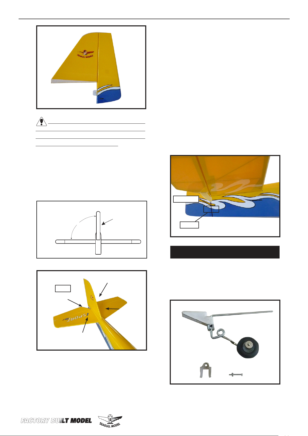
6) Using a modeling knife, carefully remove the covering that overlaps the stabilizer mounting platform sides in the
fuselage. Remove the covering from both
the top and the bottom of the platform
sides.
7) When you are sure that everything
is aligned correctly, mix up a generous
amount of 30 Minute Epoxy. Apply a thin
layer to the top and bottom of the stabilizer mounting area and to the stabilizer
mounting platform sidesin the fuselage.
Slide the stabilizer in place and realign. Double check all of your measurements once more before the epoxy cures.
Hold the stabilizer in place with T-pins
or masking tape and remove any excess
epoxy using a paper towel and rubbing
alcohol.
INSTALLING VERTICAL STABILIZER
1) While holding the vertical stabilizer
.
rmly in place, use a pen and draw a
line on each side of the vertical stabilizer
where it meets the top of the fuselage.
Epoxy
Pen.
2) Using a modeling knife, remove the
covering from over the precut hinge slot
cut into the lower rear portion of the fuselage.
22
8) Aer the epoxy has fully cured, remove
the masking tape or T-pins used to hold
the stabilizer in place. Carefully inspect
the glue joints. Use more epoxy to ll
in any gaps that may exist that were not
lled previously and clean up the excess
using a paper towel and rubbing alcohol.
Remove the covering.
Page 23
WWW.SEAGULLMODELS.COM
When cutting through the covering to remove it, cut with only enough pressure to only
cut through the covering itself. Cutting into
the balsa structure may weaken it.
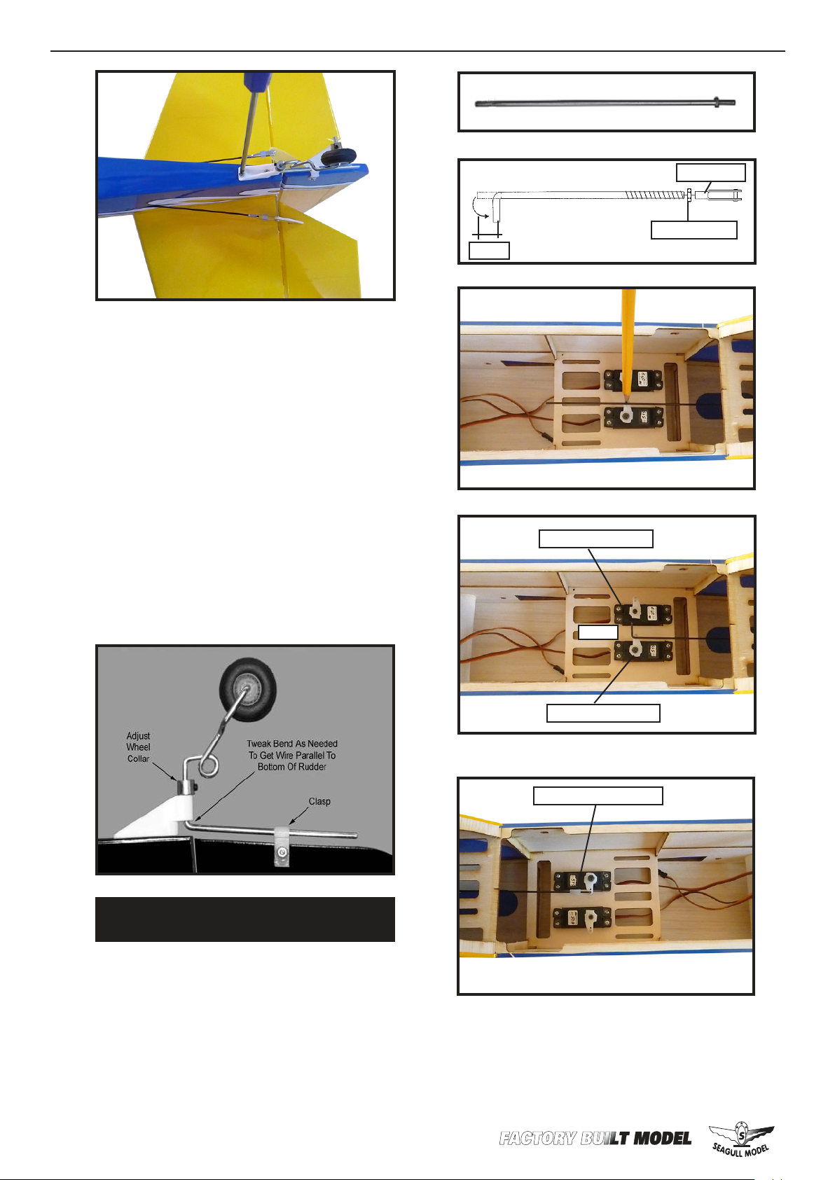
3) Slide the vertical stabilizer back inplace. Using a triangle, check to ensure
that the vertical stabilizer is aligned 90º
to the horizontal stabilizer.
4) When you are sure that everything is
aligned correctly, mix up a generous
amount of Flash 30 Minute Epoxy. Apply a thin layer to the mounting slot
and to bottom of the vertical stabilizer
mounting area. Apply epoxy to the bottom and top edges of the ller block and
to the lower hinge also. Set the stabilizer
in place and realign. Double check all of
your measurements once more before
the epoxy cures. Hold the stabilizer in
place with T-pins or masking tape and
remove any excess epoxy using a paper
towel and rubbing alcohol. Allow the
epoxy to fully cure before proceeding.
Horizontal
Stabilizer.
Epoxy
C/A glue.
Vertical
90º
Stabilizer.
Hinge.
TAILWHEEL INSTALLATION.
1) Mount the tailwheel assembly in place
on the lower rear end of the fuselage, using two M3 x12mm screws.
23
Page 24
ISPORT 10-15cc
2) Adjust the wheel collar shown to set the
height of the tailwheel wire. en check
to see if the long steering leg of the tailwheel wire is parallel to the bottom of the
rudder. e wire may need to be tweaked
slightly to make it parallel.
Instruction Manual.
M2 clevis.
M2 lock nut.
8mm
3) Slide the Nylon Rudder Steering Clasp
onto the bottom of the rudder and onto
the tailwheel wire at the same time. Locate the clasp at the halfway point on the
wire, and then drill a hole for the M2 x
15mm Bolt. Insert the bolt through the
hole and tighten down the M2 Hex nut to
clamp the bracket in place.
Elevator pushrod.
8mm
Rudder pushrod.
Nylon Snap keeper.
24
ELEVATOR - RUDDER PUSHROD
HORN INSTALLATION.
1) Install the elevator control horn using
the same method as with the aileron control horns.
2) Position the elevator control horn on
the both side of elevator.
Page 25
M2 clevis.
WWW.SEAGULLMODELS.COM
Fuel Tubing.
Hex Nut.
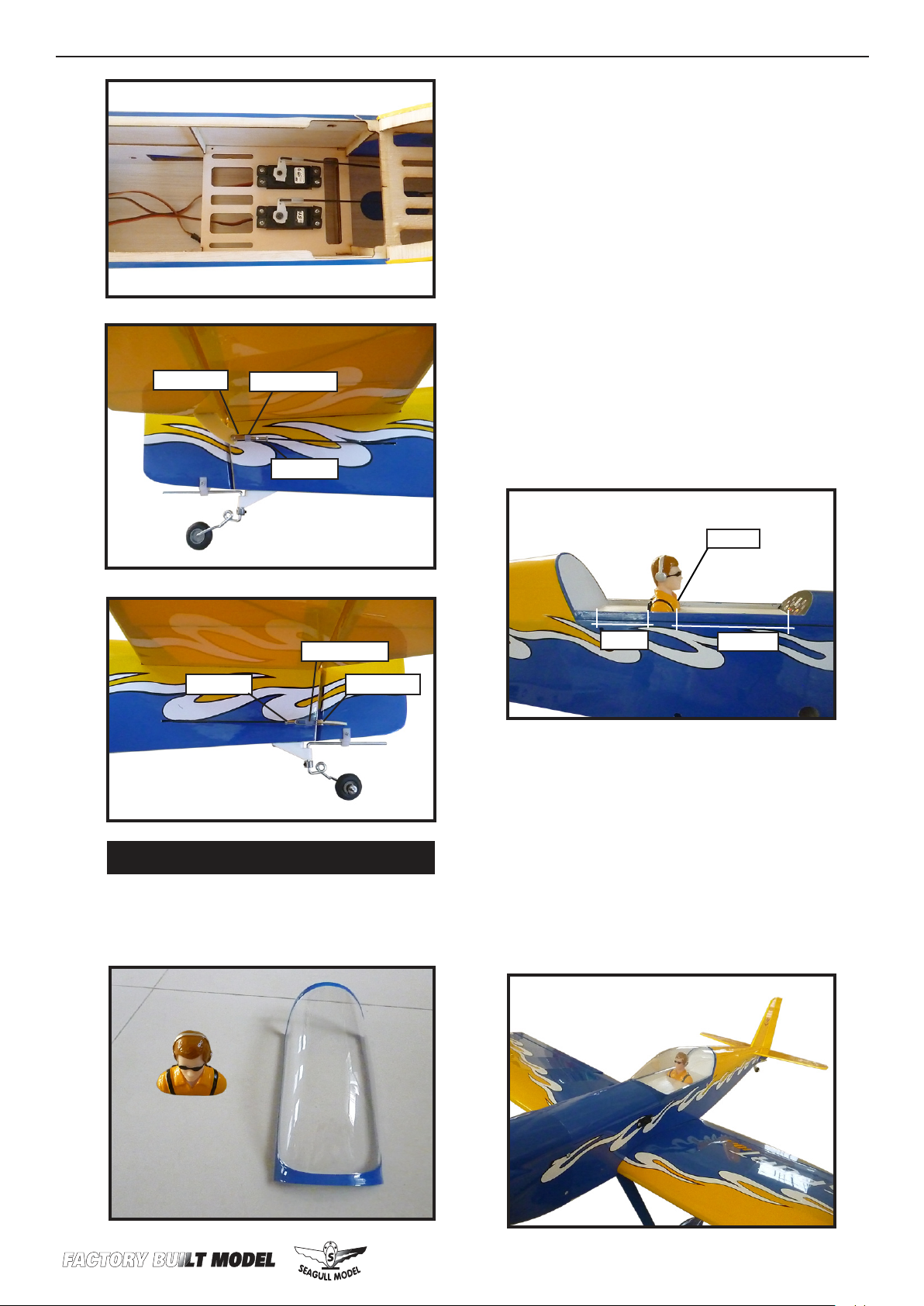
2) A scale pilot is included with this ARF.
e Seagull Pilot included tting well to
the cockpit. (or you can order others scale
pilot gures made by Seagull factory.
ey are available at Seagull distributors.)
If you are going to install a pilot gure,
please use a sanding bar to sand the base
of the gure so that it is at.
3) Position the pilot gure on the canopy
oor as show. Locate the oval shaped on
the canopy oor and remove the covering. Use epoxy to glue this into the base
of the pilot gure and glue the cockpit
panel in place with C/A glue, please see
pictures as shown.
Fuel Tubing.
Hex Nut.
INSTALLATION PILOT .
1) Locate items necessary to install pilot,
.
M2 clevis.
cockpit panel, and canopy.
Ep ox y.
70mm
125mm
4) Position the canopy onto the fuselage.
Trace around the canopy and onto the fuselage using a felt-tipped pen.
- Apply a bead of canopy glue around the
inside edge of the canopy. Position the
canopy onto the hatch. Use tape to hold
the canopy secure until the glue fully
cures.
25
Page 26
ISPORT 10-15cc
Instruction Manual.
APPLY THE DECALS.
1) If all the decals are precut and ready to
stick. Please be certain the model is clean
and free from oily ngerprints and dust.
Position decal on the model where desired, using the photos on the box and
aid in their location.
2) If all the decals are not precut, please
use scissors or a sharp hobby knife to cut
the decals from the sheet. Please be certain the model is clean and free from oily
ngerprints and dust. Position decal on
the model where desired, using the photos on the box and aid in their location.
INSTALLING THE RECEIVER.
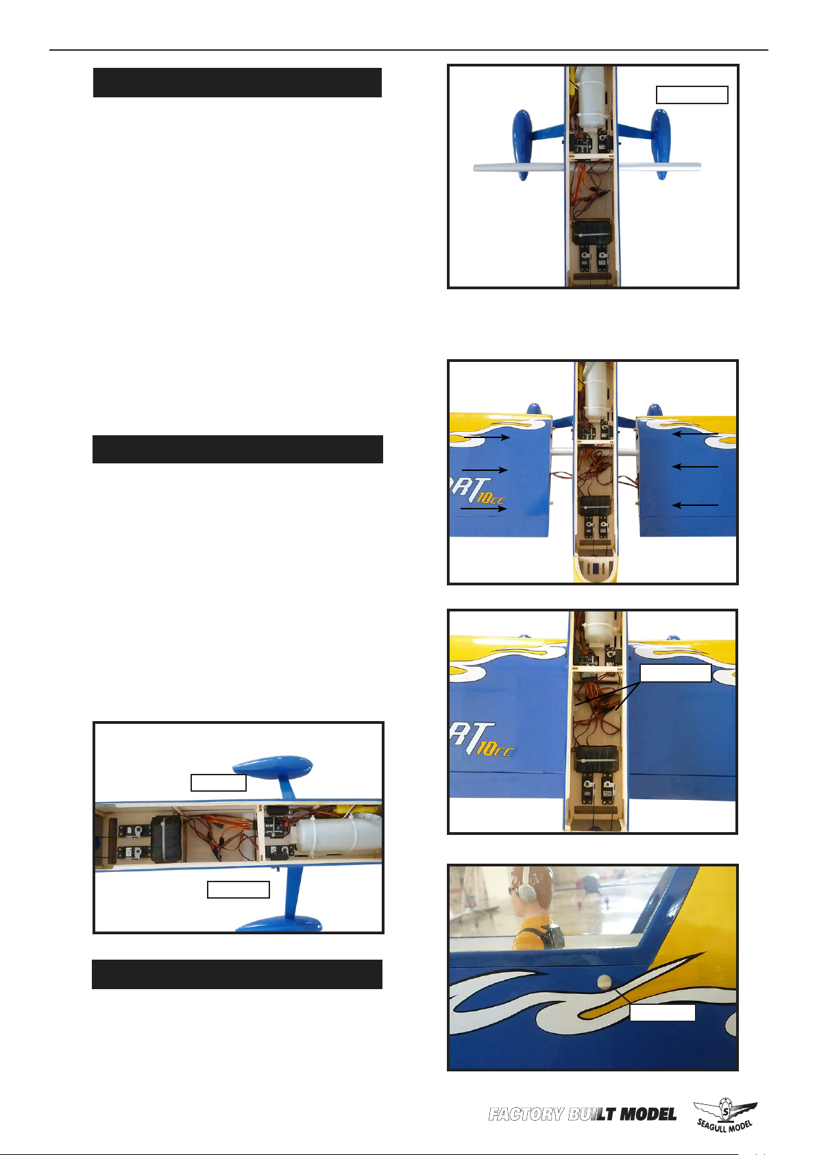
Wing tube.
Insert two wing panels as pictures below.
1) Plug the ve servo leads and the switch
lead into the receiver. Plug the battery
pack lead into the switch also.
2) Wrap the receiver and battery pack in
the protective foam rubber to protect
them from vibration.
3) Route the antenna in the antenna tube
inside the fuselage and secure it to the
bottom of fuselage using a plastic tape.
Batt er y.
Wing bolt.
26
Receiver.
ATTACHMENT WING- FUSELAGE.
Attach the aluminium tube into fuselage.
4x20mm.
Page 27
WWW.SEAGULLMODELS.COM
BALANCING.
1) It is critical that your airplane be
balanced correctly. Improper balance will
cause your plane to lose control and
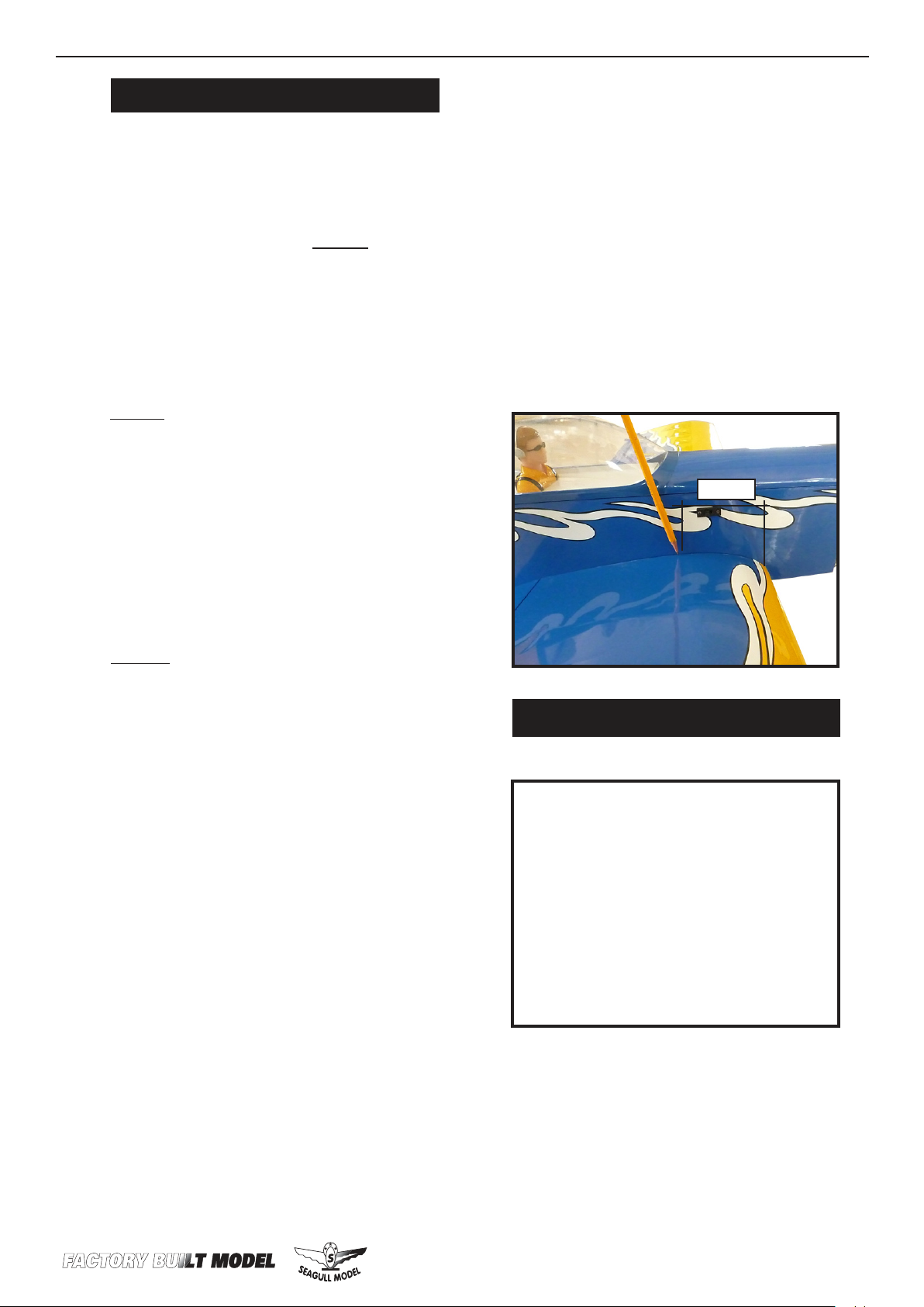
crash. THE CENTER OF GRAVITY IS LOCATED 75MM BACK
FROM THE LEADING EDGE OF
THE WING AT THE WING ROOT.
2) Mount the wing to the fuselage. Using
a couple of pieces of masking tape, place
them on the bottom side of the wing
75mm back from the leading edge of the
wing at the wing root.
3) Turn the airplane upside down. Place
your ngers on the masking tape and
carefully li the plane .
Li the model. If the tail drops when
you li, the model is “tail heavy” and you
must add weight* to the nose. If the nose
drops, it is “nose heavy” and you must
add weight* to the tail to balance.
*If possible, rst attempt to balance the
model by changing the position of the receiver battery and receiver. If you are unable to obtain good balance by doing so,
then it will be necessary to add weight to
the nose or tail to achieve the
proper balance point.
75 mm
Accurately mark the balance point on
the botttom of the wing on both sides of
the fuselage. e balance point is located
75mm back from the leading edge of the
wing at the wing root. is is the balance point at which your model should
balance for your rst ights. Later, you
may wish to experiment by shiing the
balance up to 10mm forward or back to
change the ying characteristics. Moving the balance forward may improve
the smoothness and arrow- like tracking,
but it may then require more speed for
take o and make it more dicult to slow
down for landing. Moving the balance a
makes the model more agile with a lighter and snappier ”feel”. In any case,please
start at the location we recommend .
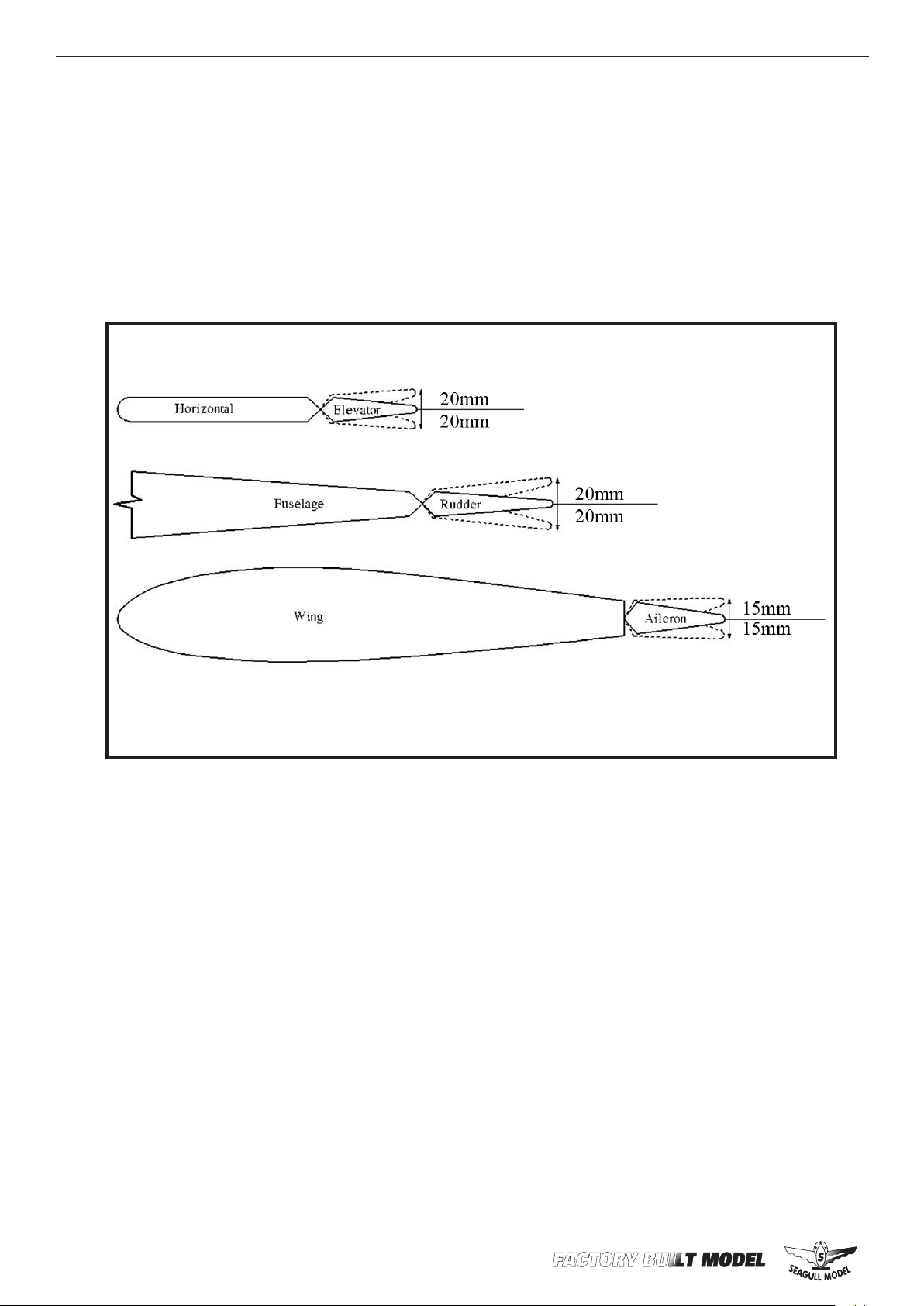
CONTROL THROWS.
Ailerons:
Up : 15 mm
Down : 15 mm
Elevator:
Up : 20 mm
Down : 20 mm
Rudder:
Right : 20 mm
Le : 20 mm
With the wing attached to the fuselage,
all parts of the model installed ( ready to
y), and empty fuel tanks, hold the model at the marked balance point with the
stabilizer level.
27
Page 28
ISPORT 10-15cc
Instruction Manual.
28
Page 29

WWW.SEAGULLMODELS.COM
FLIGHT PREPARATION. PREFLIGHT CHECK.
Check the operation and direction
of the elevator, rudder, ailerons and
throttle.
A) Plug in your radio system per the
manufacturer’s instructions and turn
everything on.
B) Check the elevator rst. Pull
back on the elevator stick. e elevator halves should move up. If it they do
not, ip the servo reversing switch on
your transmitter to change the direc-
C) Check the rudder. Looking from
behind the airplane, move the rudder
stick to the right. e rudder should
move to the right. If it does not, ip
the servo reversing switch on your
transmitter to change the direction.
1) Completely charge your transmitter and receiver batteries before
your rst day of ying.
2) Check every bolt and every glue
joint in the ISPORT to ensure that
everything is tight and well bonded.
3) Double check the balance of the
airplane. Do this with the fuel tank
empty.
4) Check the control surfaces. All
should move in the correct direction
and not bind in any way.
5) If your radio transmitter is
equipped with dual rate switches double check that they are on the low rate
setting for your rst few ights.
D) Check the throttle. Moving the
throttle stick forward should open the
carburetor barrel. If it does not, ip the
servo reversing switch on your trans-
E) From behind the airplane, look
at the aileron on the right wing half.
Move the aileron stick to the right.
e right aileron should move up and
the other aileron should move down.
If it does not, ip the servo reversing
switch on your transmitter to change
the direction.
We wish you many safe and enjoyable ights
with your ISPORT.
6) Check to ensure the control surfaces are moving the proper amount
for both low and high rate settings.
7) Check the receiver antenna. It
should be fully extended and not
coiled up inside the fuselage.
8) Properly balance the propeller.
An out of balance propeller will cause
excessive vibration which could lead
to engine and/or airframe failure.
2929
Page 30

ISPORT 10-15cc
Instruction Manual.
FOR USA MARKET ONLY.
Safety,Precautions and Warnings
As the user of this product, you are solely responsible for operating it in a manner that does not endanger
yourself and others or result in damage to the product or the property of others. Carefully follow the directions and warnings for this and any optional support equipment (chargers, rechargeable battery packs, etc.)
that you use.
is model is controlled by a radio signal that is subject to interference from many sources outside your
control. is interference can cause momentary loss of control so it is necessary to always keep a safe distance in all directions around your model, as this margin will help to avoid collisions or injury.
• Always operate your model in an open area away from cars, trac or people.
• Avoid operating your model in the street where injury or damage can occur.
• Never operate the model out into the street or populated areas for any reason.
• Never operate your model with low transmitter batteries.
• Carefully follow the directions and warnings for this and any optional support equipment (chargers, re-
chargeable battery packs, etc.) that you use.
• Keep all chemicals, small parts and anything electrical out of the reach of children.
• Moisture causes damage to electronics. Avoid water exposure to all equipment not specically designed
and protected for this purpose.
Warranty Period:
Exclusive Warranty- Horizon Hobby, Inc., (Horizon) warranties that the Products purchased (the “Product”) will be free from defects in materials and workmanship at the date of purchase by the Purchaser.
Limited Warranty
(a) is warranty is limited to the original Purchaser (“Purchaser”) and is not transferable. REPAIR OR
REPLACEMENT AS PROVIDED UNDER THIS WARRANTY IS THE EXCLUSIVE REMEDY OF THE
PURCHASER. is warranty covers only those Products purchased from an authorized Horizon dealer. ird party transactions are not covered by this warranty. Proof of purchase is required for warranty
claims. Further, Horizon reserves the right to change or modify this warranty without notice and disclaims
all other warranties, express or implied.
(b) Limitations- HORIZON MAKES NO WARRANTY OR REPRESENTATION, EXPRESS OR IMPLIED, ABOUT NONINFRINGEMENT, MERCHANTABILITY OR FITNESS FOR A PARTICULAR
PURPOSE OF THE PRODUCT. THE PURCHASER ACKNOWLEDGES THAT THEY ALONE HAVE
DETERMINED THAT THE PRODUCT WILL SUITABLY MEET THE REQUIREMENTS OF THE PURCHASER’S INTENDED USE.
(c) Purchaser Remedy- Horizon’s sole obligation hereunder shall be that Horizon will, at its option, (i) repair or (ii) replace, any Product determined by Horizon to be defective. In the event of a defect, these are
the Purchaser’s exclusive remedies. Horizon reserves the right to inspect any and all equipment involved
in a warranty claim. Repair or replacement decisions are at the sole discretion of Horizon. is warranty
does not cover cosmetic damage or damage due to acts of God, accident, misuse, abuse, negligence, commercial use, or modication of or to any part of the Product. is warranty does not cover damage due to
improper installation, operation, maintenance, or attempted repair by anyone other than Horizon. Return
of any goods by Purchaser must be approved in writing by Horizon before shipment.
30
Damage Limits:
HORIZON SHALL NOT BE LIABLE FOR SPECIAL, INDIRECT OR CONSEQUENTIAL DAMAGES,
LOSS OF PROFITS OR PRODUCTION OR COMMERCIAL LOSS IN ANY WAY CONNECTED WITH
THE PRODUCT, WHETHER SUCH CLAIM IS BASED IN CONTRACT, WARRANTY, NEGLIGENCE,
OR STRICT LIABILITY. Further, in no event shall the liability of Horizon exceed the individual price of the
Product on which liability is asserted. As Horizon has no control over use, setup, nal assembly, modication or misuse, no liability shall be assumed nor accepted for any resulting damage or injury. By the act of
use, setup or assembly, the user accepts all resulting liability.
Page 31

WWW.SEAGULLMODELS.COM
If you as the Purchaser or user are not prepared to accept the liability associated with the use of this Product,
you are advised to return this Product immediately in new and unused condition to the place of purchase.
Law: ese Terms are governed by Illinois law (without regard to conict of law principals).
Safety Precautions:
is is a sophisticated hobby Product and not a toy. It must be operated with caution and common sense
and requires some basic mechanical ability. Failure to operate this Product in a safe and responsible manner could result in injury or damage to the Product or other property. is Product is not intended for use
by children without direct adult supervision. e Product manual contains instructions for safety, operation and maintenance. It is essential to read and follow all the instructions and warnings in the manual,
prior to assembly, setup or use, in order to operate correctly and avoid damage or injury.
Questions, Assistance, and Repairs:
Your local hobby store and/or place of purchase cannot provide warranty support or repair. Once assembly,
setup or use of the Product has been started, you must contact Horizon directly. is will enable Horizon to
better answer your questions and service you in the event that you may need any assistance. For questions
or assistance, please direct your email to [email protected], or call 877.504.0233 toll free
to speak to a service technician.
Inspection or Repairs
If this Product needs to be inspected or repaired, please call for a Return Merchandise Authorization
(RMA). Pack the Product securely using a shipping carton. Please note that original boxes may be included, but are not designed to withstand the rigors of shipping without additional protection. Ship via a
carrier that provides tracking and insurance for lost or damaged parcels, as Horizon is not responsible for
merchandise until it arrives and is accepted at our facility. A Service Repair Request is available at www.
horizonhobby.com on the “Support” tab. If you do not have internet access, please include a letter with
your complete name, street address, email address and phone number where you can be reached during
business days, your RMA number, a list of the included items, method of payment for any non-warranty
expenses and a brief summary of the problem. Your original sales receipt must also be included for warranty consideration. Be sure your name, address, and RMA number are clearly written on the outside of
the shipping carton.
Warranty Inspection and Repairs
To receive warranty service, you must include your original sales receipt verifying the proof-of-purchase
date. Provided warranty conditions have been met, your Product will be repaired or replaced free of charge.
Repair or replacement decisions are at the sole discretion of Horizon Hobby.
Non-Warranty Repairs
Should your repair not be covered by warranty the repair will be completed and payment will be required without notication or estimate of the expense unless the expense exceeds 50% of the retail purchase cost. By submitting the item for repair you are agreeing to payment of the repair without notication.
Repair estimates are available upon request. You must include this request with your repair. Non-warranty
repair estimates will be billed a minimum of ½ hour of labor. In addition you will be billed for return
freight. Please advise us of your preferred method of payment. Horizon accepts money orders and cashiers
checks, as well as Visa, MasterCard, American Express, and Discover cards. If you choose to pay by credit
card, please include your credit card number and expiration date. Any repair le unpaid or unclaimed
aer 90 days will be considered abandoned and will be disposed of accordingly. Please note: non-warranty
repair is only available on electronics and model engines.
Electronics and engines requiring inspection or repair should be shipped to the following address:
Horizon Service Center
4105 Fieldstone Road
Champaign, Illinois 61822
All other Products requiring warranty inspection or repair should be shipped to the following address:
Horizon Product Support
4105 Fieldstone Road
Champaign, Illinois 61822
Please call 877-504-0233 with any questions or concerns regarding this product or warranty.
31
 Loading...