

Page 1
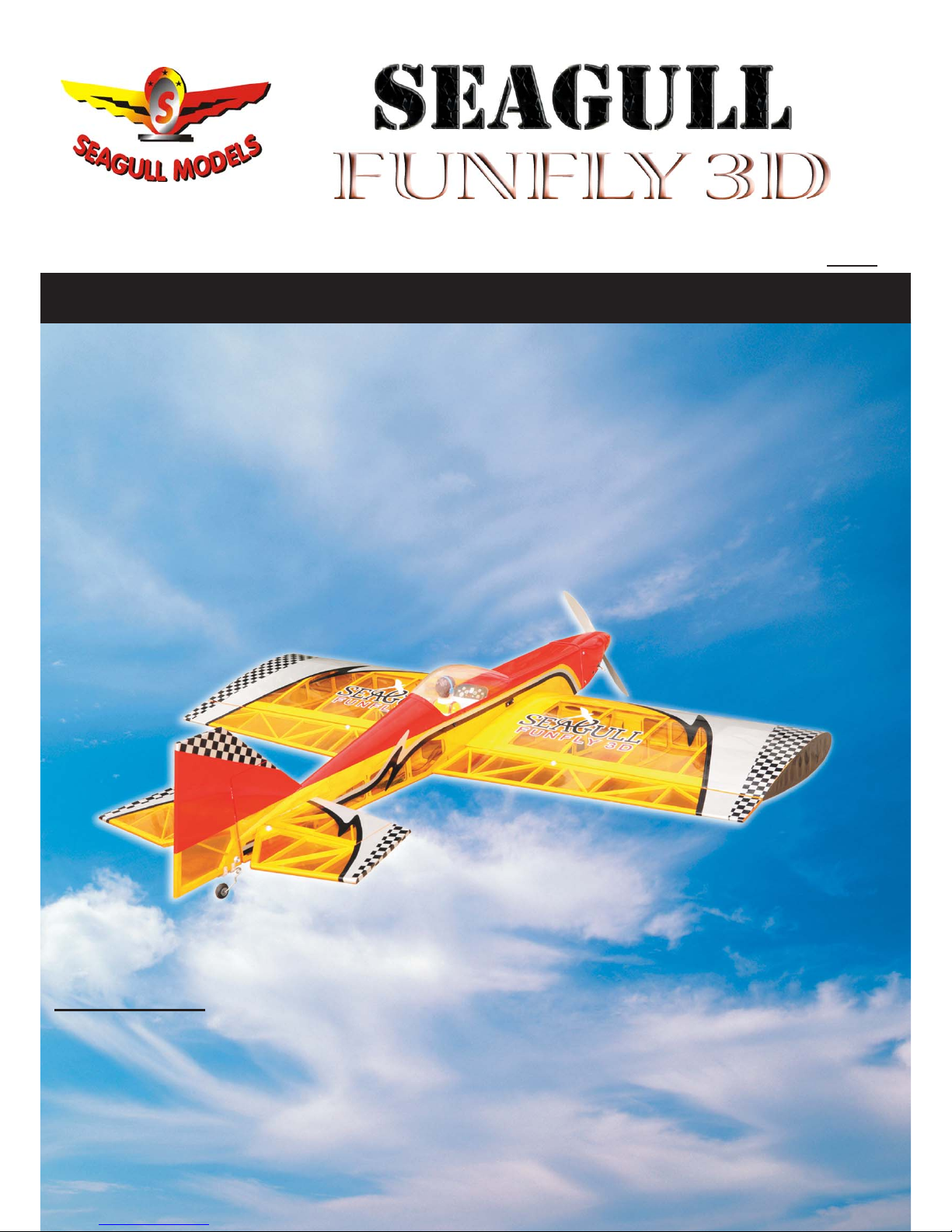
“Graphics and specifications may change without notice”.
MS:40
ASSEMBLY MANUAL
Specifications:
Wing span ----------------------------50.4in (128cm).
Wing area -----------------840.1sq.in (54.2sq dm).
Weight ----------------------- 5.1-5.7lbs (2.3-2.6kg).
Length ---------------------------------51.6in (131cm).
Engine --------------- 0.46-0.55cu.in ----2-stroke.
0.72cu.in ---4-stroke.
Radio --------------------4 channels with 6 servos.
Electric conversion: optional
Page 2
SEAGULL FUNFLY 3D. Instruction Manual.
2
INTRODUCTION.
Thank you for choosing the SEAGULL FUNFLY 3D ARTF by SEAGULL MODELS COMPANY LTD.
The SEAGULL FUNFLY 3D was designed with the intermediate/advanced sport flyer in mind. It
is a semi scale airplane which is easy to fly and quick to assemble. The airframe is conventionally
built using balsa, plywood to make it stronger than the average ARTF, yet the design allows the
aeroplane to be kept light. You will find that most of the work has been done for you already. The motor
mount has been fitted and the hinges are pre-installed. Flying the SEAGULL FUNFLY 3D is simply
a joy.
This instruction manual is designed to help you build a great flying aeroplane. Please read this
manual thoroughly before starting assembly of your SEAGULL FUNFLY 3D . Use the parts listing
below to identify all parts.
WARNING.
Please be aware that this aeroplane is not a toy and if it is assembled or used incorrectly it
will cause injury to people or property. WHEN YOU FLY THIS AEROPLANE YOU ASSUME
ALL RISK & RESPONSIBILITY.
If you are inexperienced with basic R/C flight we strongly recommend you contact your R/C supplier
and join your local R/C Model Flying Club. R/C Model Flying Clubs offer a variety of training
procedures designed to help the new pilot on his way to successful R/C flight. They will also be able
to advise on any insurance and safety regulations that may apply.
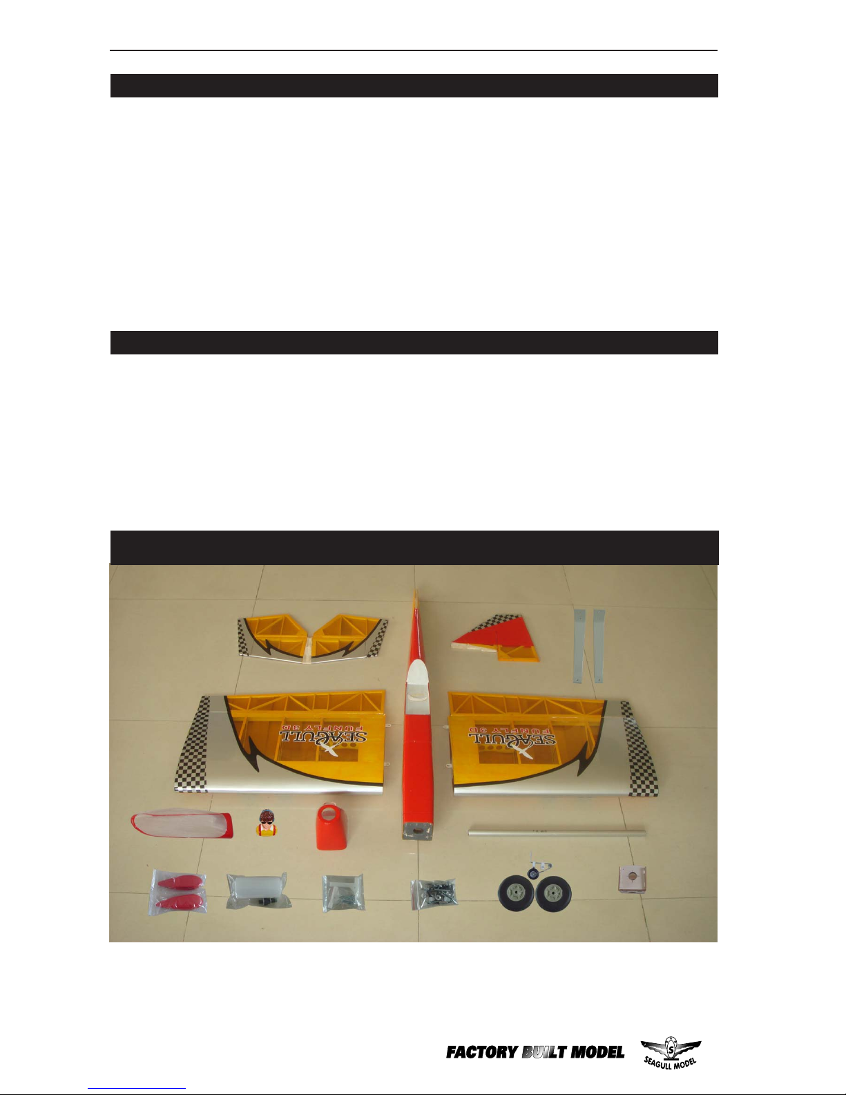
KIT CONTENTS
1
2
9
3
4
5
8
6
7
10
4
11
12
14
13
15
Page 3
3
www.seagullmodels.com
ADDITIONAL ITEMS REQUIRED.
0.46-0.55 2-stroke.
0.72 4-stroke.
Computer radio with 6 servos.
Glow plug to suit engine.
Propeller to suit engine.
Protective foam rubber for radio
system.
TOOLS & SUPPLIES NEEDED.
Thick cyanoacrylate glue.
30 minute epoxy.
5 minute epoxy.
Hand or electric drill.
Assorted drill bits.
Modelling knife.
Straight edge ruler.
2mm ball driver.
Phillips head screwdriver.
220 grit sandpaper.
90° square or builder’s triangle.
Wire cutters.
Masking tape & T-pins.
Thread-lock.
Paper towels.
The control surfaces, including the
ailerons, elevators, and rudder, are
prehinged with hinges installed, but
the hinges are not glued in place. It
is imperative that you properly
adhere the hinges in place per the
steps that follow using a high-quality
thin C/A glue.
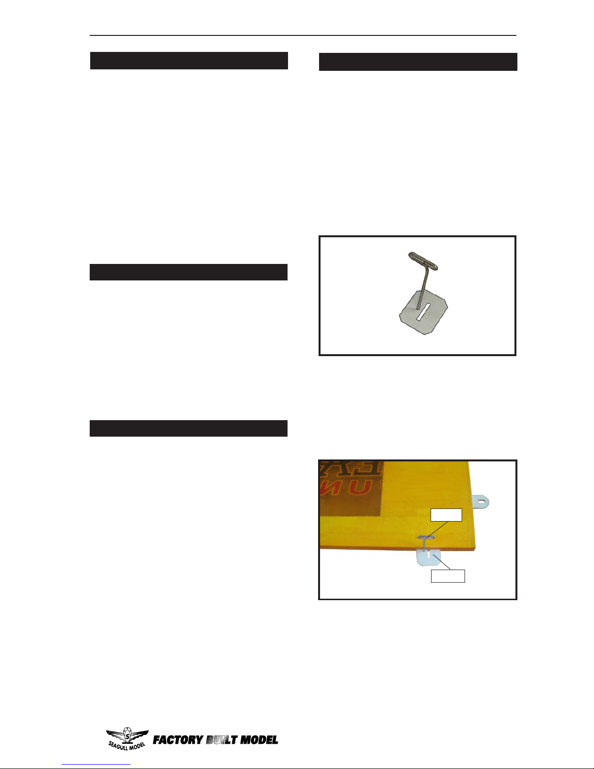
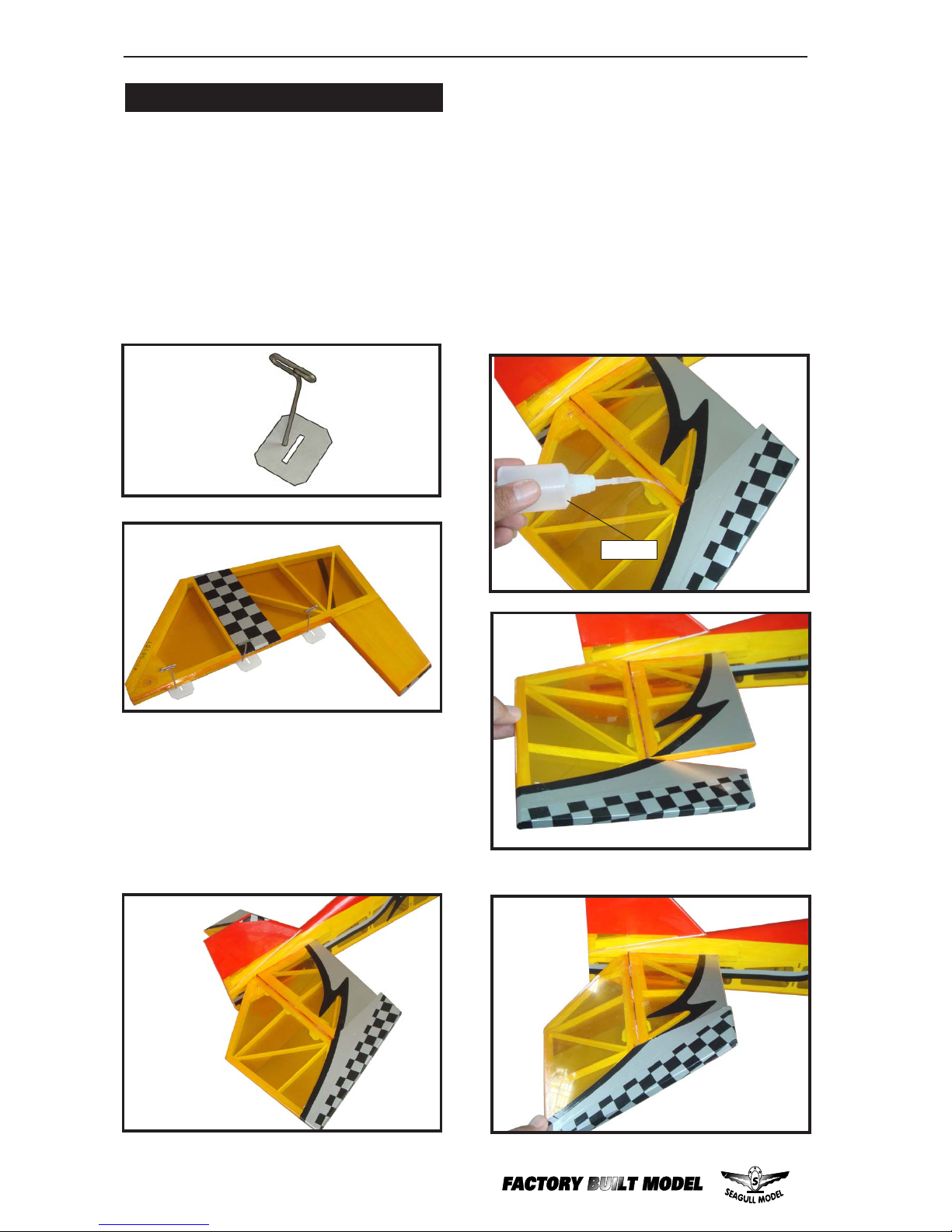
2) Remove each hinge from the wing panel
and aileron and place a T-pin in the center of
each hinge. Slide each hinge into the aileron
until the T -pin is snug against the aileron. This
will help ensure an equal amount of hinge is
on either side of the hinge line when the aileron
is mounted to the wing panel.
HINGING THE AILERONS .
Note:
1) Carefully remove the aileron from one
of the wing panels. Note the position of the
hinges.
Hinge.
3) Slide the aileron on the wing panel until
there is only a slight gap. The hinge is now
centered on the wing panel and aileron.
Remove the T-pins and snug the aileron
against the wing panel. A gap of 1/64” or less
should be maintained between the wing panel
and aileron.
T-pin.
1 Fuselage
2 Left wing panel
3 Right wing panel
4 Tail set (2)
5 Pilot
6 Aluminum wing tube
7 Fiberglass cowl
8 Canopy
9 Fuel tank
10 Landing gear
11 Fiberglass whl pants
12 Engine mount
13 wheel(2)
14 Hardware bag included
15 EP conversion pack
KIT CONTENS.TS
Page 4

SEAGULL FUNFLY 3D. Instruction Manual.
4
INSTALL THE AILERONS CONTROL
HORN.
1) Locate the hardware necessary to install
the control horns for the ailerons.
8) After both ailerons are securely hinged,
firmly grasp the wing panel and aileron to
make sure the hinges are securely glued and
cannot be pulled out. Do this by carefully
applying medium pressure, trying to separate
the aileron from the wing panel. Use caution
not to crush the wing structure.
7) Repeat this process with the other wing
panel, securely hinging the aileron in place.
6) Using C/A remover/debonder and a
paper towel, remove any excess C/A glue that
may have accumulated on the wing or in the
aileron hinge area.
5) Turn the wing panel over and deflect the
aileron in the opposite direction from the
opposite side. Apply thin C/A glue to each
hinge, making sure that the C/A penetrates into
both the aileron and wing panel.
Work the aileron up and down several
times to “work in” the hinges and
Note:
4) Deflect the aileron and completely
saturate each hinge with thin C/A glue. The
ailerons front surface should lightly contact the
wing during this procedure. Ideally, when the
hinges are glued in place, a 1/64” gap or less
will be maintained throughout the lengh of the
aileron to the wing panel hinge line.
The hinge is constructed of a special
material that allows the C/A to wick
or penetrate and distribute
throughout the hinge, securely
bonding it to the wood structure of
the wing panel and aileron.
Note:
Hinge.
HINGING THE RUDDER.
Glue the rudder hinges in place using the
same techniques used to hinge the ailerons.
Page 5
5
www.seagullmodels.com
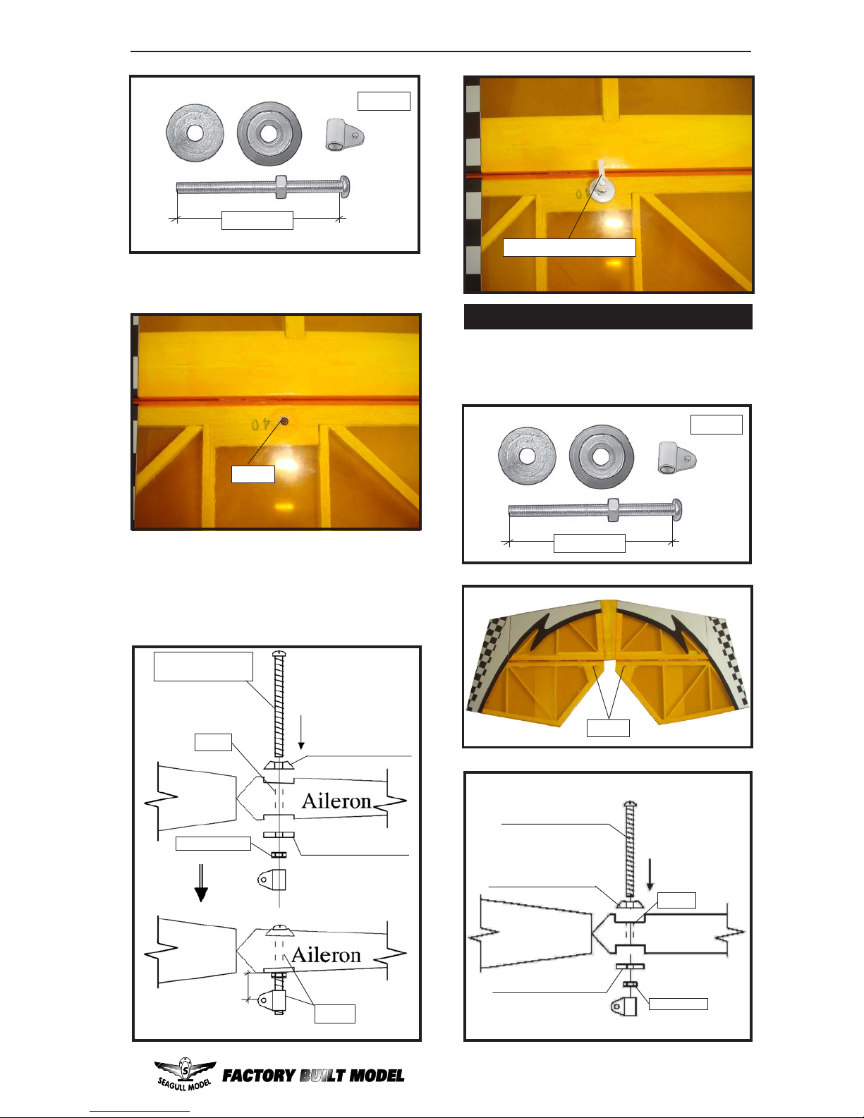
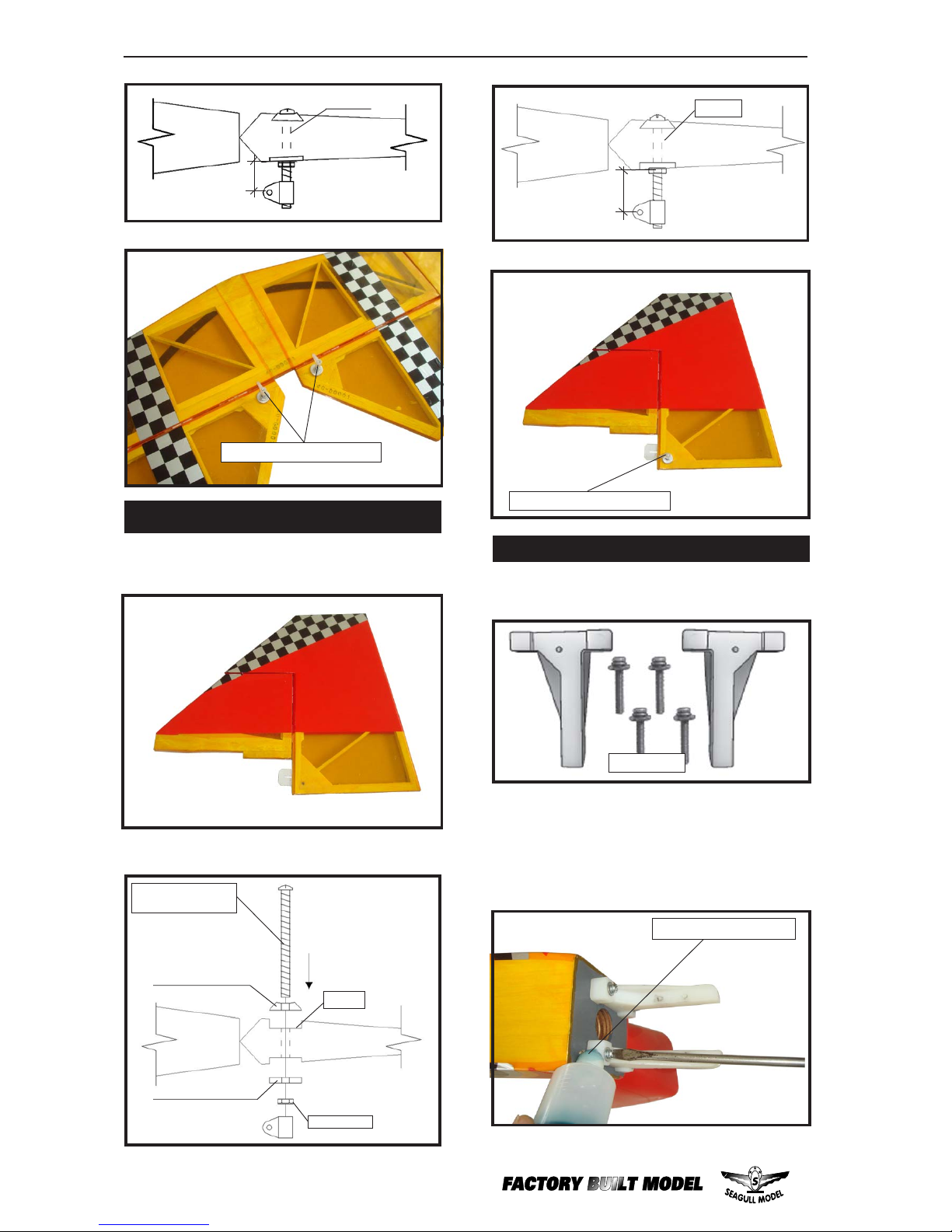
2) Position the control horn on the bottom of
the aileron. You will see pre-drill hole 3mm for
the horn mounting screw on the aileron.
2 sets.
3x35mm.
Aileron control horn.
3) Place epoxy into hole. This will harden the
threads and prevent the crews from pulling
loose.
4) Thread a control horn end with aluminum
washer, lock nut until the top edge of the end is
18mm from the vase of the horn as shown.
3mm.
ALUMINUM WASHER.
ALUMINUM WASHER.
CONTROL HORN
M3 SCREW.
18mm.
Epoxy.
Wing
Wing
Epoxy.
M3 LOCK NUT.
3mm.
Install the elevator control horn using the
same method as same as the aileron control
horns.
INSTALL ELEVATOR CONTROL HORN.
2 sets.
3x35mm.
Aluminum Washer .
CONTROL HORN M3
M3 LOCK NUT.
Epoxy.
Aluminum Washer .
Horizontal
Stabilizer.
Elevator.
Page 6
SEAGULL FUNFLY 3D. Instruction Manual.
6
Thread locker glue.
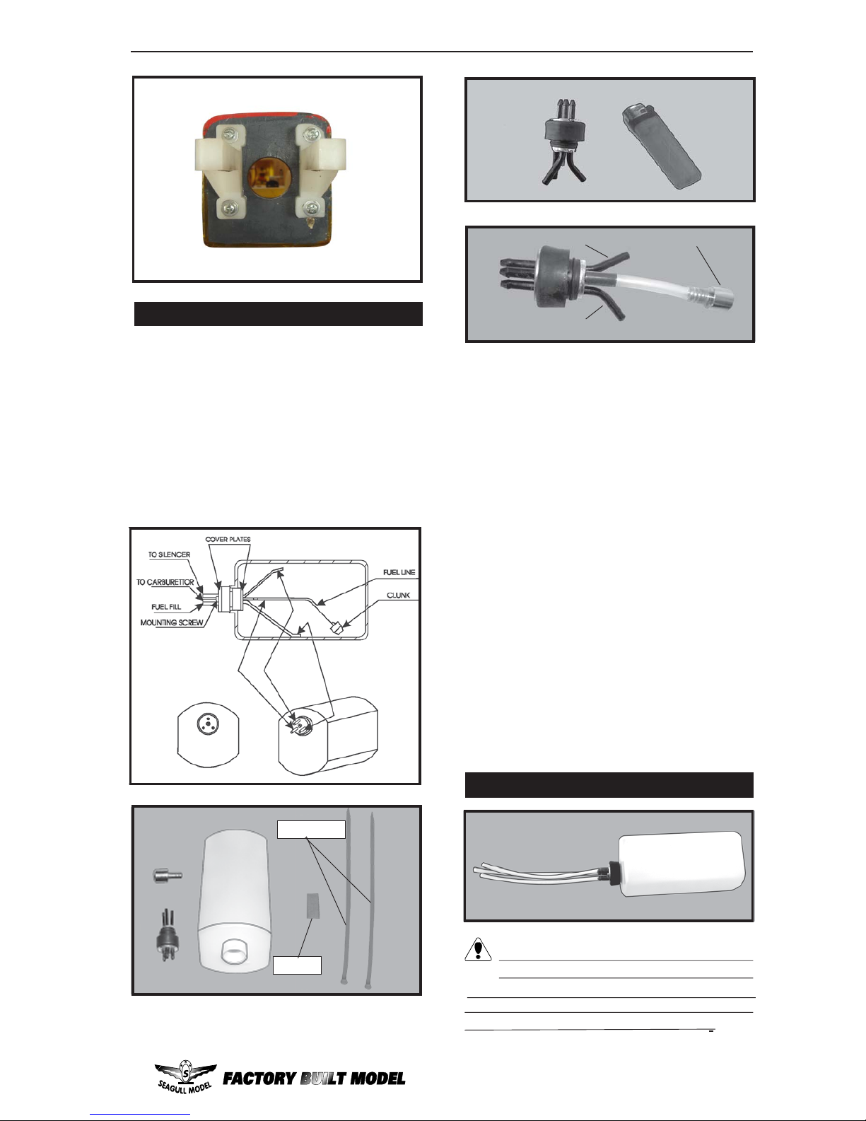
ENGINE MOUNT INST ALLATION.
1) Locate the items necessary to install the
engine mount included with your model.
2) Use four 4x30mm head bolts and four 4mm
washers to attach the engine mount rails to
the firewall. Tighten the screws . Make sure to
use threadlock on the screws to help prevent
them from vibrating loose.
4x30mm.
INSTALL RUDDER CONTROL HORN.
Repeat steps to install the rudder control
horn as same as steps done for ailerons.
Elevator control horn.
Rudder.
Aluminum Washer .
CONTROL HORN
M3 SCREW.
M3 LOCK NUT.
Epoxy.
Aluminum Washer .
Fuselage.
Fuselage.
18mm.
Epoxy.
Rudder.
Rudder control horn.
18mm.
Epoxy.
Horizontal
Stabilizer.
Elevator.
Page 7
7
www.seagullmodels.com
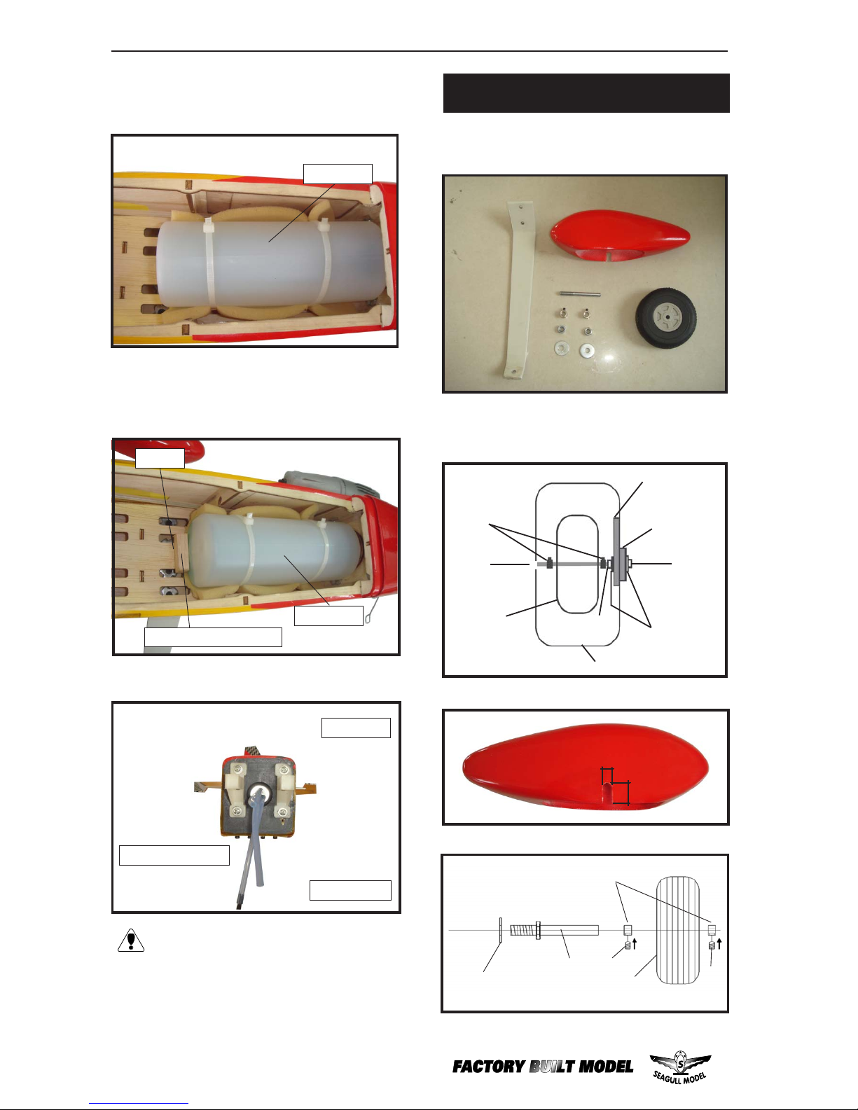
1) Using a modeling knife, carefully cut
off the rear portion of one of the 3 nylon tubes
leaving 1/2” protruding from the rear of the
stopper. This will be the fuel pick up tube.
INST ALLING THE STOPPER ASSEMBL Y .
2) Using a modeling knife, cut one length
of silicon fuel line. Connect one end of the line
to the weighted fuel pick up and the other end
to the nylon pick up tube.
3) Carefully bend the second nylon tube
up at a 45º angle. This tube is the vent tube.
4) Test fit the stopper assembly into the
tank. It may be necessary to remove some of
the flashing around the tank opening using a
modeling knife. If flashing is present, make
sure none falls into the tank.
Vent tube.
Fuel pick up tube.
Fuel fill tube.
5) With the stopper assembly in place,
the weighted pick-up should rest away from
the rear of the tank and move freely inside the
tank. The top of the vent tube should rest just
below the top of the tank. It should not touch
the top of the tank.
6) When satisfied with the alignment of
the stopper assembly tighten the 3 x 20mm
machine screw until the rubber stopper expands and seals the tank opening. Do not
overtighten the assembly as this could cause
the tank to split.
FUEL TANK INSTALLATION.
You should mark which tube is the vent
and which is the fuel pickup when you attach
fuel tubing to the tubes in the stopper. Once
the tank is installed inside the fuselage, it may
be difficult to determine which is which.
Tie wrap.
Balsa
Page 8
SEAGULL FUNFLY 3D. Instruction Manual.
8
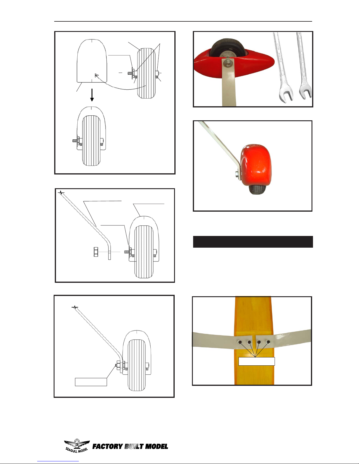
7) Slide the fuel tank into the fuselage. Guide
the lines from the tank through the hole in the
firewall.
Fuel tank.
Epoxy .
Fuel tank.
8) Use plywood template to hold in place
the fuel tank with C/A glue to secure the fuel
tank inside the fuselage.
Vent tube.
Fuel pick up tube.
Fuel fill tube.
Blow through one of the lines to ensure the fuel lines have not become kinked
inside the fuel tank compartment. Air
should flow through easily.
Wheel Collar.
Axle.
Wheel.
Nut.
Wheel Pant.
Landing Gear.
Nut.
(2) Washer .
Lite -Plywood
block.
1) Assemble and mounting the landing
gear wheels to the wheel pants as shown in
the following pictures.
2) Follow diagram below for wheel pant
installation:
WHEEL AND WHEEL PANTS
INSTALLATION.
7mm
14mm
wheel collar .
wheel.
Axle.
Washer .
M3.
M3.
Balsa wood include.
Page 9
9
www.seagullmodels.com
C/A glue.
Landing Gear.
wheel Pant.
wheel Pant.
wheel.
M3.
M3.
wheel collar.
nut.
Axle.
Washer .
3) A drop of C/A glue on the wheel collar
screws will help keep them from coming lose
during operation.
Repeat the process for the other wheel.
Locker glue.
1) The blind nuts for securing the landing
gear are already mounted inside the fuselage.
2) Using the hardware provided, mount the
main landing gear to the fuselage.
INST ALLING THE MAIN LANDING GEAR.
M4 x 20mm.
Page 10
SEAGULL FUNFLY 3D. Instruction Manual.
10
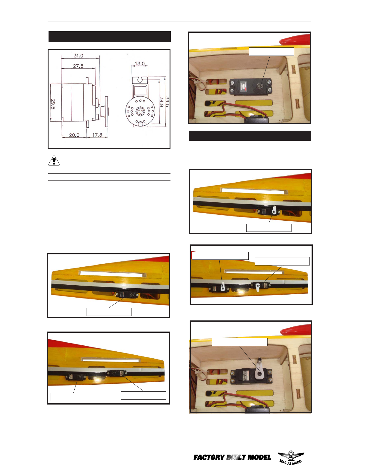
THROTTLE SERVO ARM INSTALLATION.
Install adjustable servo connector in the servo
arm as same as picture below:
Elevator servo.
Elevator servo arm.
Rudder servo arm.
Elevator servo.
Elevator servo.
Rudder servo.
1) Install the rubber grommets and brass
collets onto the throttle servo. T est fit the servo
into the aileron servo mount.
2) Secure the servos with the screws provided with your radio system.
Throttle servo arm.
Throttle servo.
INSTALLING THE FUSELAGE SERVOS.
Because the size of servos differ, you
may need to adjust the size of the precut opening in the mount. The notch in the sides of the
mount allow the servo lead to pass through.
Page 11
11
www.seagullmodels.com
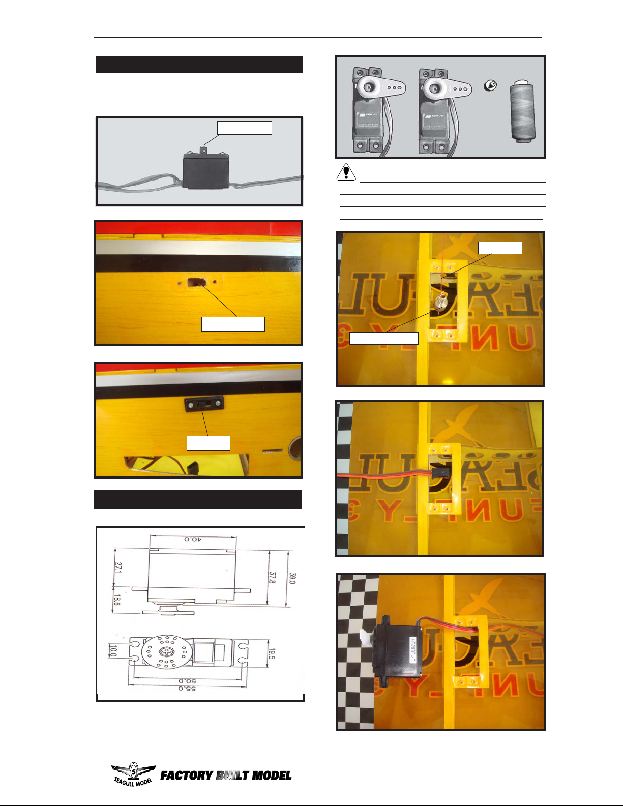
Switch.
3/ 32” Hole.
INSTALLING THE SWITCH.
Install the switch into the precut hole in the
side, in the fuselage.
Trim and cut.
INSTALLING THE AILERON
Servos.
Small weight.
Thread.
Because the size of servos differ, you
may need to adjust the size of the precut opening in the mount. The notch in the sides of
the mount allow the servo lead to pass through.
Small weight.
String.
Page 12
SEAGULL FUNFLY 3D. Instruction Manual.
12
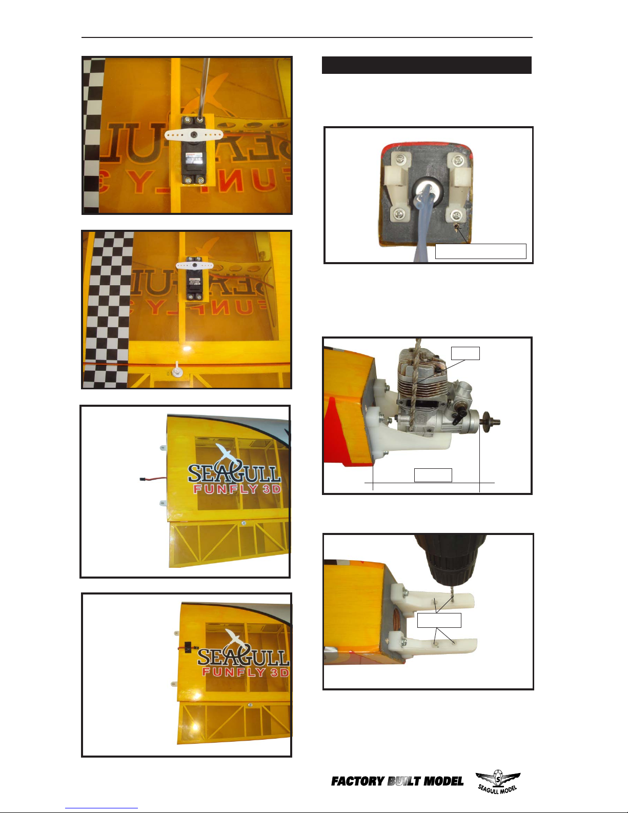
3) Use a drill to drill the four holes in the engine
mount rails.
4) On the fire wall has the location for the
throttle pusshrod tube (pre-drill).
2mm.
2mm.
Pushrod tube hole.
2) Use a pin drill and 2mm drill bit to drill a
small indentation in the mount for the engine
mounting screw.
MOUNTING THE ENGINE.
1) Position the engine with the drive washer
(110mm) forward of the firewall as shown.
1 10mm.
Page 13
13
www.seagullmodels.com
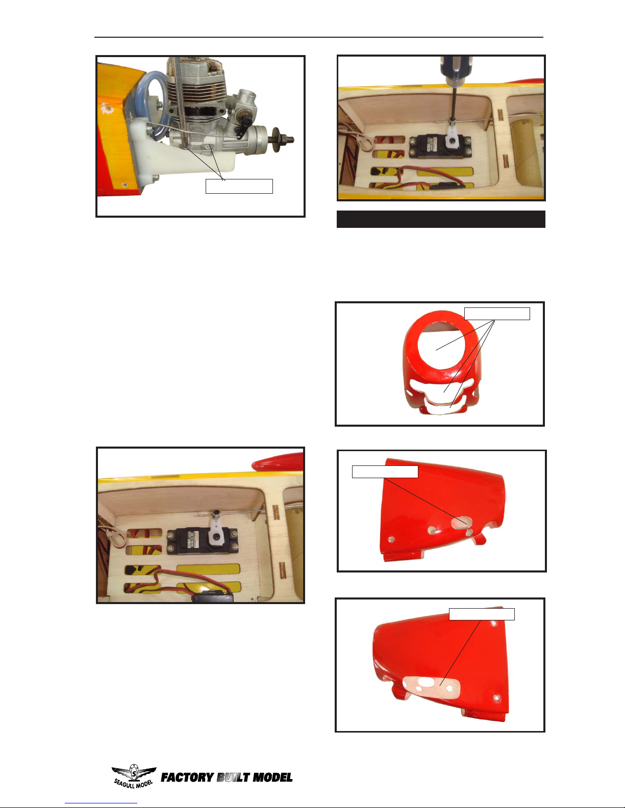
9) Move the throttle stick to the closed position
and move the carburetor to closed. Use a 1.5mm
hex wrench to tighten the screw that secures
the throttle pushrod wire. Make sure to use
threadlock on the screw so it does not vibrate
loose.
8) Reinstall the servo horn by sliding the
connector over the pushrod wire. Center the
throttle stick and trim and install the servo horn
perpendicular to the servo center line.
7) Slide the throttle pushrod wire into the tube.
Position the engine between the mounts. Use
four M3x25mm machine screws to secure the
engine to the mount as shown.
5) Slide the pushrod tube in the firewall and
guide it through the fuel tank mount. Use
medium C/A to glue the tube to the firewall and
the fuel tank mount.
6) Connect the Z-bend in the 450mm throttle
pushrod to the outer hole of the carburetor arm.
M3x25mm
Trim and cut.
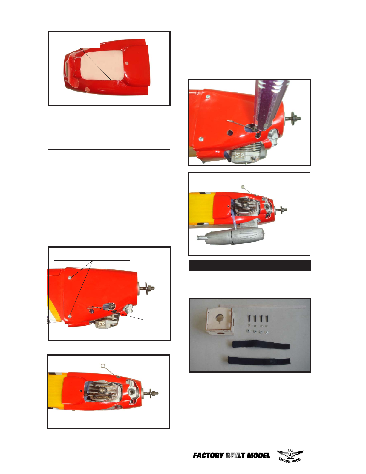
COWLING.
Trim and cut.
1) Slide the fiberglass cowl over the engine and line up the back edge of the cowl with
the marks you made on the fuselage then trim
and cut as shown.
Trim and cut.
Page 14
SEAGULL FUNFLY 3D. Instruction Manual.
14
3) Install the muffler and muffler extension
onto the engine and make the cutout in the
cowl for muffler clearance. Connect the fuel
and pressure lines to the carburetor, muffler
and fuel filler valve. Secure the cowl to fuselage using the M3x10mm screws.
ELECTRIC POWER CONVERSION.
1) Locate the items neccessary to install the
electric power conversion parts included with
your model.
- Model size: .35-.45 size models
- Motor: 35mm 830 rev per volt
- Propeller: 11x7
- ESC: 50A
- Lipo Batteries: 4 cell 3200mA
Recommendation EP parts as shown (not
included with your model)
Machine screw M3x10mm.
Needle valve.
Because of the size of the cowl, it may be necessary to use a needle valve extension for the
high speed needle valve. Make this out of sufficient length 1.5mm wire and install it into the
end of the needle valve. Secure the wire in
place by tightening the set screw in the side of
the needle valve.
2) While keeping the back edge of the
cowl flush with the marks, align the front of
the cowl with the crankshaft of the engine. The
front of the cowl should be positioned so the
crankshaft is in nearly the middle of the cowl
opening. Use the spinner backplate as a guide.
Hold the cowl firmly in place using pieces of
masking tape.
Trim and cut.
Page 15
15
www.seagullmodels.com
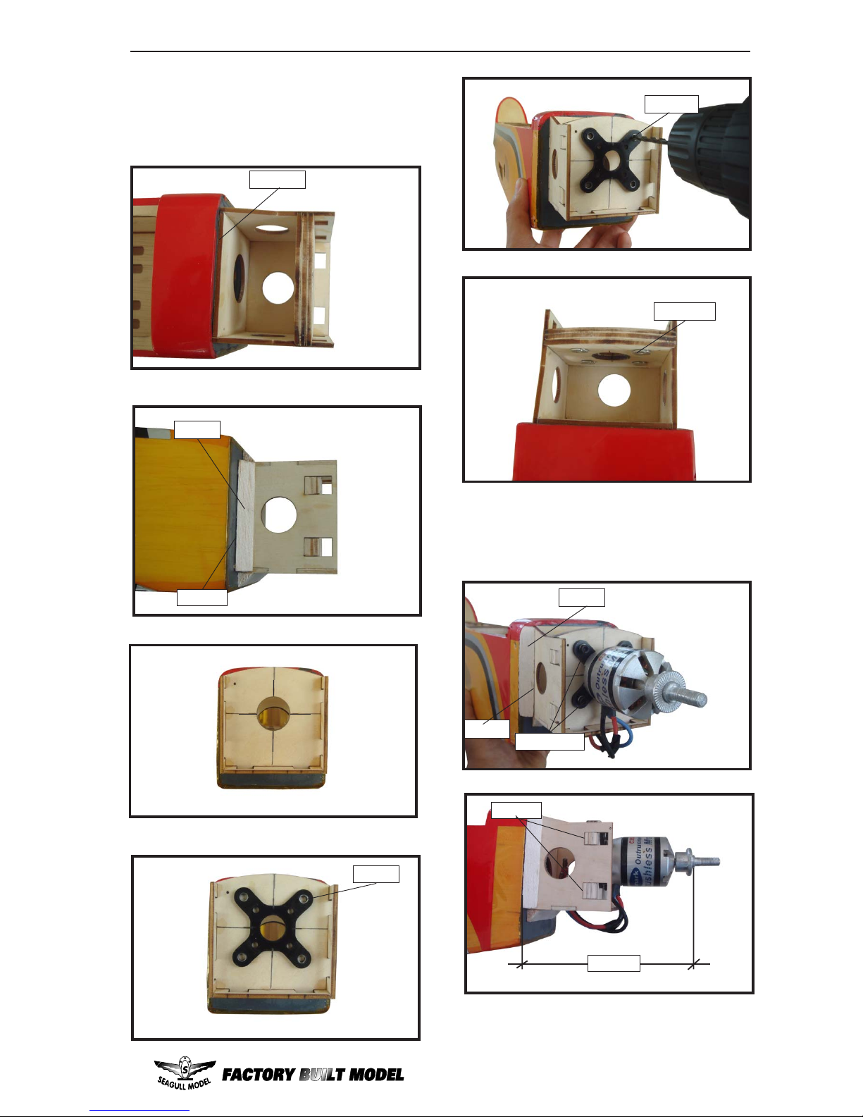
2) Attach the electric motor box to the firewall
suitable with the cross lines drawn on the electric
motor box and firewall. Using epoxy and balsa
stick to secure the motor box to the firewall.
Please see pictures below.
Epoxy.
4mm.
Balsa.
Epoxy.
4mm.
Blind nut.
3) Attach the motor to the front of the electric
motor box using four 3mm blind nut, four
M3x15mm hex head bolts to secure the motor.
Please see picture shown.
140mm.
M3x15mm.
Balsa.
Epoxy.
Epoxy.
Page 16
SEAGULL FUNFLY 3D. Instruction Manual.
16
INST ALLING THE HORIZONTAL ST ABILIZER.
1) Using a ruler and a pen, locate the
centerline of the horizontal stabilizer, at the
trailing edge, and place a mark. Use a triangle
and extend this mark, from back to front,
across the top of the stabilizer. Also extend
this mark down the back of the trailing edge of
the stabilizer.
2) Using a modeling knife, carefully remove
the covering at mounting slot of horizontal
stabilizer.
3) Put the stabilizer into place in the
position of the fuselage.
Draw center line.
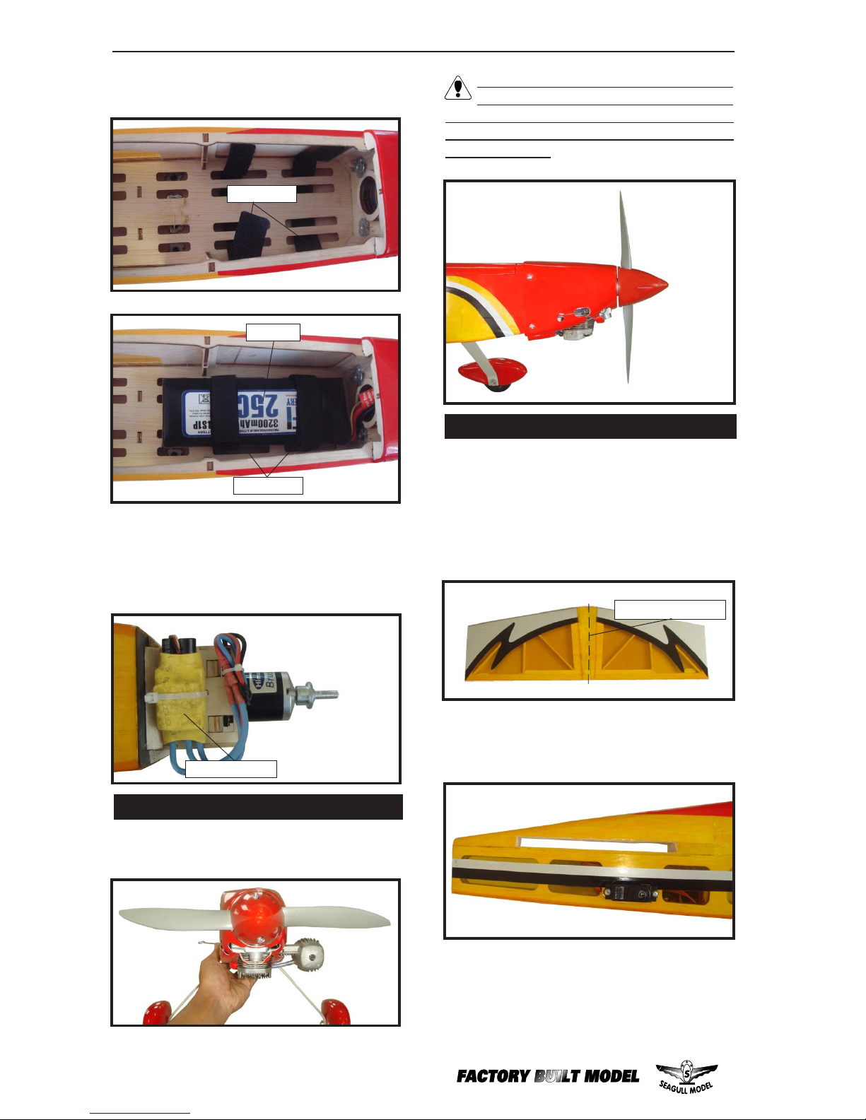
The propeller should not touch any part
of the spinner cone. If it does, use a
sharp modeling knife and carefully trim away
the spinner cone where the propeller comes
in contact with it.
speed control.
5) Attach the speed control to the side of the
motor box using two-sided tape and tie wraps.
Connect the appropriate leads from the speed
control to the motor. Make sure the leads will
not interfere with the operation of the motor.
Tie wraps.
4) Locate the plywood battery tray to the
fuselage.
Battery.
INSTALLING THE SPINNER.
Install the spinner backplate, propeller and
spinner cone.
Tie wraps.
Page 17
17
www.seagullmodels.com
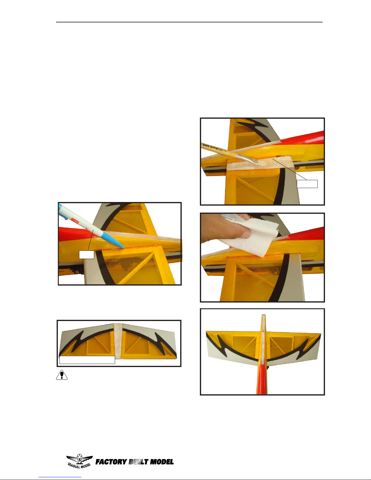
6) With the stabilizer held firmly in place,
use a pen and draw lines onto the stabilizer
where it and the fuselage sides meet. Do this
on both the right and left sides and top and
bottom of the stabilizer.
5) When you are satisfied with the alignment, hold the stabilizer in place with T- pins
or masking tape, but do not glue at this time.
Pen.
7) Remove the stabilizer . Using the lines
you just drew as a guide, carefully remove the
covering from between them using a modeling knife.
Remove the covering.
8) Using a modeling knife, carefully remove the covering that overlaps the stabilizer
mounting platform sides in the fuselage. Remove the covering from both the top and the
bottom of the platform sides.
When cutting through the covering to
remove it, cut with only enough pressure
to only cut through the covering itself. Cutting into the balsa structure may weaken
it.
4) Install the stabilizer onto the fuselage.
Align the centerline drawn on the top and the
rear of the stabilizer with the centre of the fuselage. When that is aligned, hold the stabilizer in that position using T-pins or masking
tape. Align the horizontal stabilizer with the
wing. When viewed from the rear, the horizontal stabilizer should be level with the wing.
If it is not level, use sandpaper and sand down
the high side of the stabilizer mounting platform until the proper alignment is achieved.
The tips of the stabilizer should also be equal
distance from the tips of the wing.
10) After the epoxy has fully cured, remove the masking tape or T -pins used to hold
the stabilizer in place. Carefully inspect the
glue joints. Use more epoxy to fill in any gaps
that may exist that were not filled previously
and clean up the excess using a paper towel
and rubbing alcohol.
Epoxy.
9) When you are sure that everything is
aligned correctly, mix up a generous amount
of 30 Minute Epoxy. Apply a thin layer to the
bottom of the stabilizer mounting area and to
the stabilizer mounting platform sides in the
fuselage. Putting the stabilizer in place and
realign. Double check all of your measurements once more before the epoxy cures.
Hold the stabilizer in place with T -pins or masking tape and remove any excess epoxy using
a paper towel and rubbing alcohol.
Page 18
SEAGULL FUNFLY 3D. Instruction Manual.
18
HINGING THE ELEVATOR.
Epoxy.
1) Carefully remove the elevator from one
of the fuselage panel. Note the position of the
hinges.
2) Remove each hinge from the fuselage
panel and elevator and place a T-pin in the
center of each hinge. Slide each hinge into the
elevator until the T-pin is snug against the
elevator. This will help ensure an equal amount
of hinge is on either side of the hinge line when
the elevator is mounted to the fuselage .
3) Slide the elevator on the fuselage panel
until there is only a slight gap. The hinge is
now centered on the fuselage panel and
elevator. Remove the T-pins and snug the
elevator against the fuselage panel. A gap of
1/64” or less should be maintained between
the fuselage panel and elevator.
4)Deflect the elevator and completely
saturate each hinge with thin C/A glue. The
elevator front surface should lightly contact
the fuselage during this procedure. Ideally,
when the hinges are glued in place, a 1/64”
gap or less will be maintained throughout the
lengh of the elevator to the fuselage panel hinge
line.
Note: The hinge is constructed of a special
material that allows the C/A to wick or penetrate
and distribute throughout the hinge, securely
bonding it to the wood structure of the fuselage
panel and rudder.
Page 19
19
www.seagullmodels.com
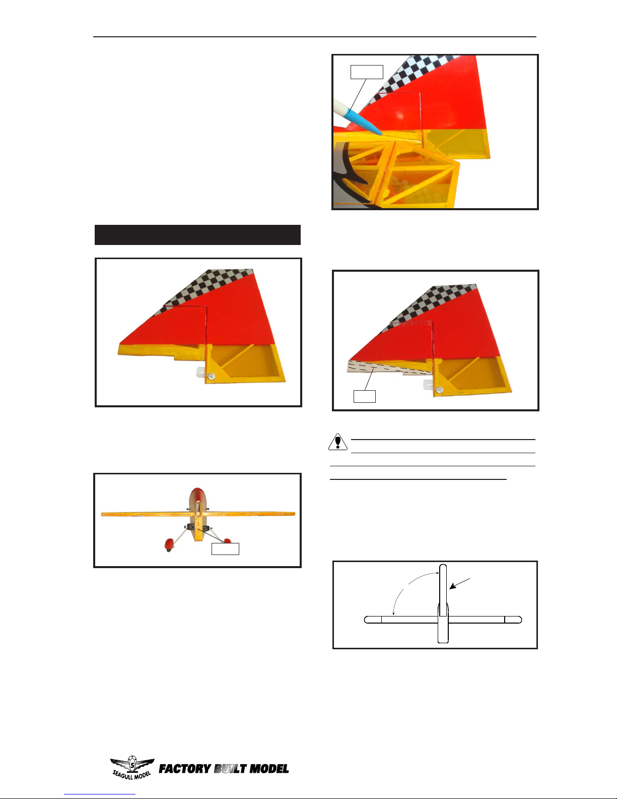
5) Slide the vertical stabilizer back in
place. Using a triangle, check to ensure that
the vertical stabilizer is aligned 90º to the horizontal stabilizer.
When cutting through the covering to re-
move it, cut with only enough pressure to
only cut through the covering itself. Cutting
into the balsa structure may weaken it.
2) Slide the vertical stabilizer into the slot
in the top of the fuselage. The rear edge of
the stabilizer should be flush with the rear edge
of the fuselage and the lower rudder hinge
should engage the precut hinge slot in the
lower fuselage. The bottom edge of the stabilizer should also be firmly pushed against the
top of the horizontal stabilizer .
3) While holding the vertical stabilizer
firmly in place, use a pen and draw a line on
each side of the vertical stabilizer where it
meets the top of the fuselage.
Pen.
Cut.
4) Remove the stabilizer. Using a mod-
eling knife, remove the covering from below
the lines you drew.
INSTALLING VERITICAL FIN.
1) Using a modeling knife, remove the
covering from over the precut hinge slot cut
into the lower rear portion of the fuselage.
Cut.
5) Turn the fuselage panel over and deflect
the elevator in the opposite direction from the
opposite side. Apply thin C/A glue to each
hinge, making sure that the C/A penetrates into
the elevator and fuselage panel.
6) Using C/A remover/debonder and a
paper towel, remove any excess C/A glue that
may have accumulated on the fuselage or in
the elevator hinge area.
Work the elevator up and down several
times to “work in” the hinges and check
for proper movement.
Note:
90º
Vertical
Stabilizer.
Horizontal
Stabilizer.
Page 20
SEAGULL FUNFLY 3D. Instruction Manual.
20
ELEVATOR AND RUDDER
PUSHROD HORN INSTALLATION.
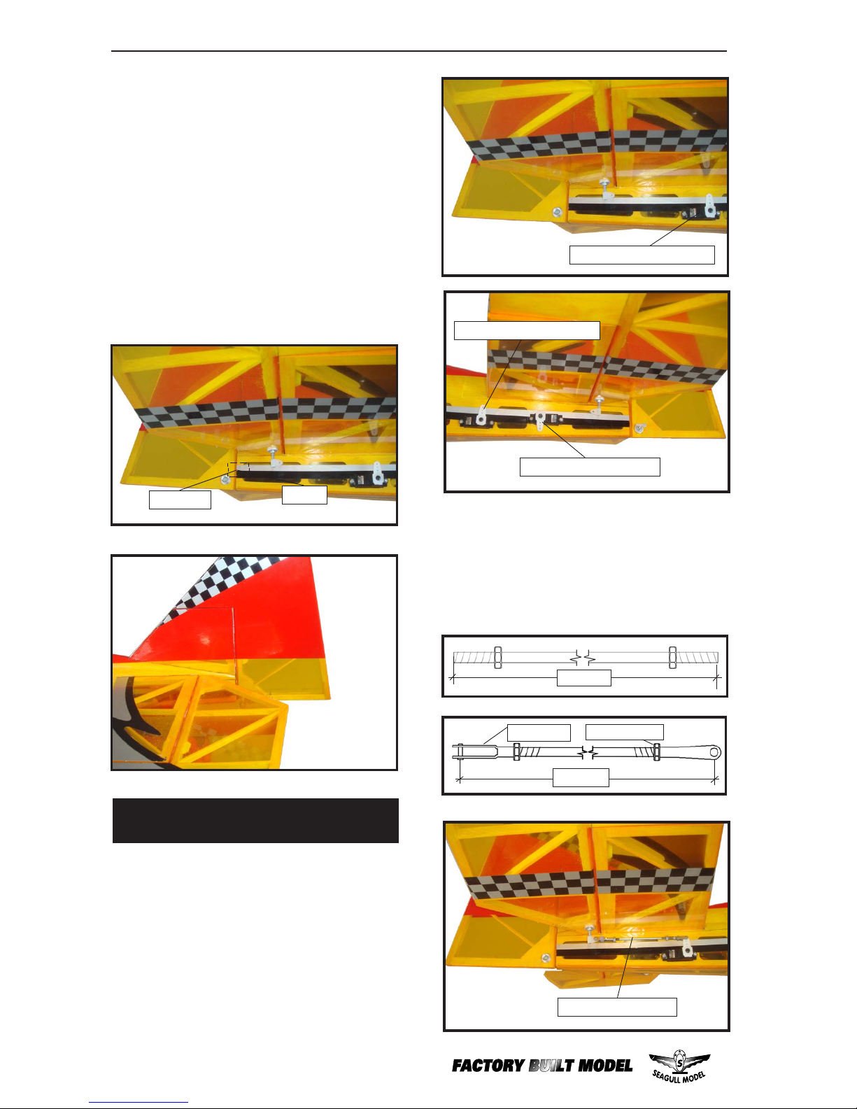
1) Install the elevator control horn using
the same method as with the aileron control
horns.
2) Position the elevator control horn on
the both side of elevator.
6) When you are sure that everything is
aligned correctly , mix up a generous amount of
Flash 30 Minute Epoxy. Apply a thin layer to the
mounting slot in the top of the fuselage and to
the sides and bottom of the vertical stabilizer
mounting area. Apply epoxy to the bottom and
top edges of the filler block and to the lower
hinge also. Set the stabilizer in place and realign. Double check all of your measurements
once more before the epoxy cures. Hold the
stabilizer in place with T-pins or masking tape
and remove any excess epoxy using a paper
towel and rubbing alcohol. Allow the epoxy to
fully cure before proceeding.
C/A glue.
Hinge.
4) Elevator and rudder pushrods assembly
as pictures below.
3) Thread one clevis and M3 lock nut on
to each elevator control rod. Thread the horns
on until they are flush with the ends of the control rods.
M3 lock nut.
M3 clevis.
90mm.
120mm.
Rudder control horn.
Elevator control horn.
Elevator pushrod.
Elevator control horn.
Page 21
21
www.seagullmodels.com
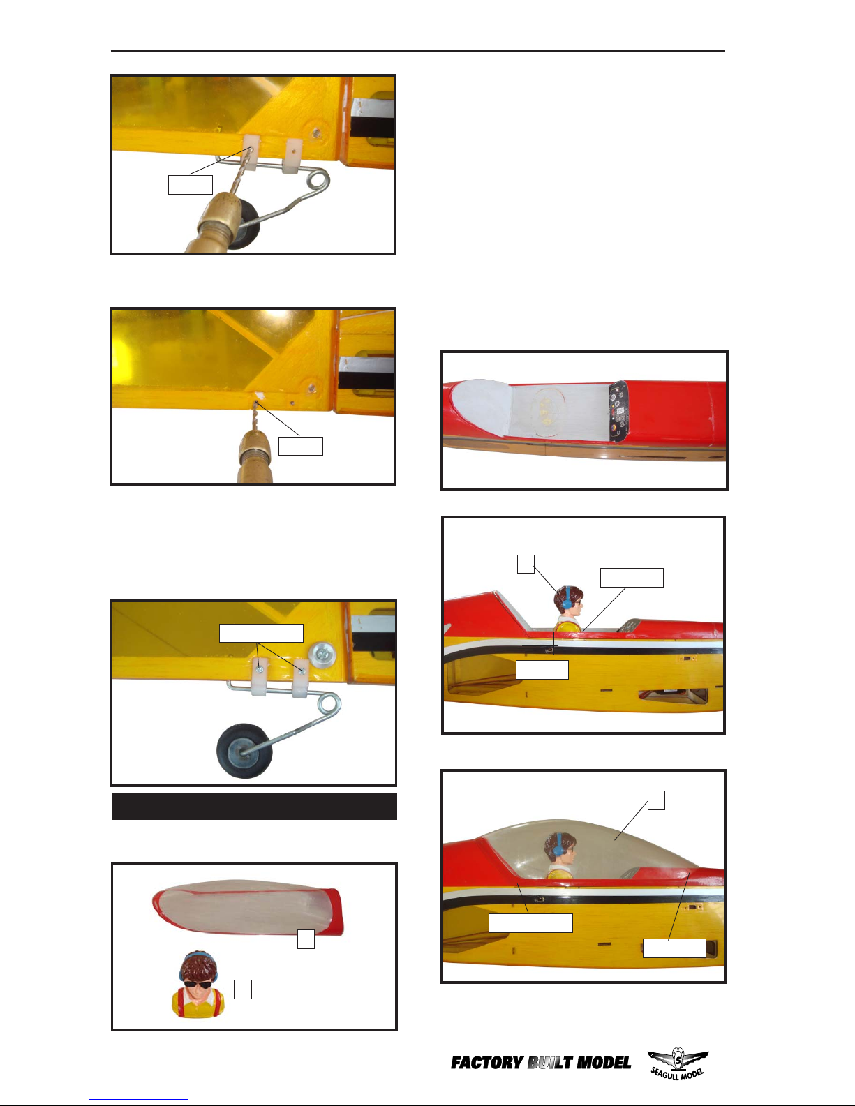
3) Mark where you drill the two locations
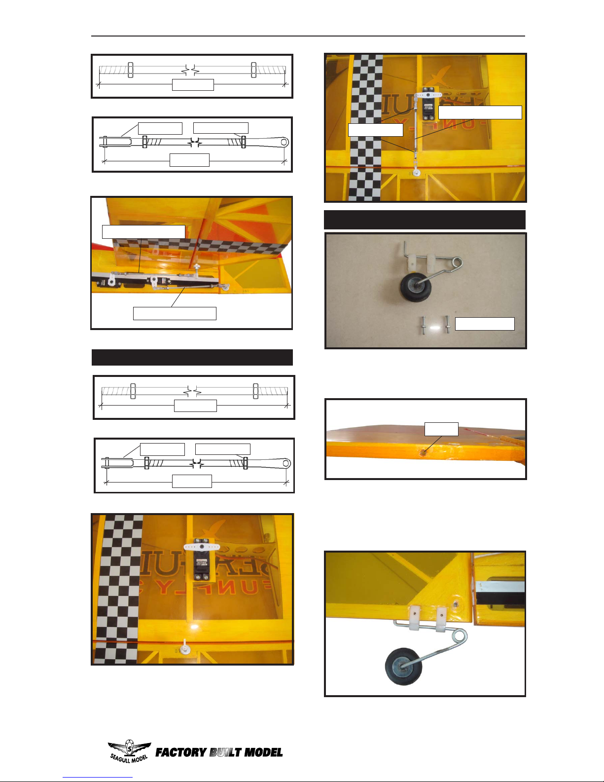
for the tailwheel support.
Elevator pushrod.
Rudder pushrod.
M3 lock nut.
M3 clevis.
110mm.
140mm.
INSTALLATION TAILWHEEL.
1) Locate the pre-drilled hole in the bottom
of the rudder. This is the hole for the vertical
shaft of the tailwheel assembly.
2) Temporarily mount the tailwheel
assembly to the bottom of rudder. Do not glue
at this time. Slide the nylon tailwheel support
brackets to be evenly spaced along the
tailwheel wire.
M2 x 12mm.
Epoxy.
AILERON PUSHROD HORN INSTALLA TION.
M3 lock nut.
M3 clevis.
110mm.
140mm.
Aileron pushrod.
M3 lock nut.
Page 22
SEAGULL FUNFLY 3D. Instruction Manual.
22
4) Drill through the bottom of the rudder
with the 2mm drill.
5) Using a toothpick insert a small amount
of the epoxy in the hole in the bottom of the
rudder. Insert the vertical tailwheel wire into the
hole with the epoxy and mount the nylon
brackets to the rudder with the hardware
included.
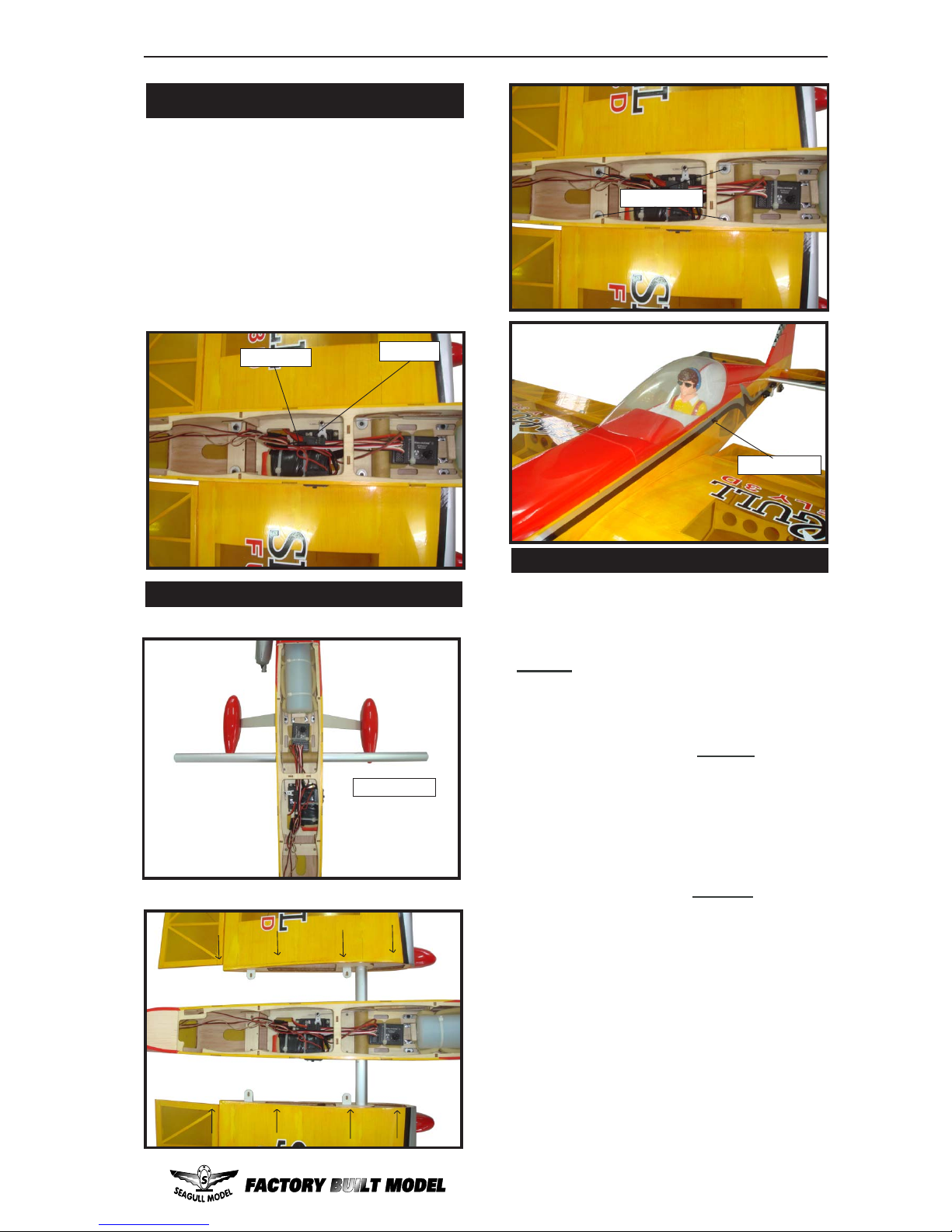
INSTALLATION PILOT AND CANOPY.
2
1
1) Locate items necessary to install pilot, and
canopy.
2) A scale pilot is included with this ARF. The
Seagull Pilot included fitting well to the cockpit.
(or you can order others scale pilot figures
made by Seagull factory. They are available at
Seagull distributors.)
3) Position the pilot figure on the canopy floor
as show. Locate the oval shaped on the canopy
floor and remove the covering. Use epoxy to
glue this into the base of the pilot figure and
glue the cockpit panel in place with C/A glue,
please see pictures as shown.
If you are going to install a pilot figure, please
use a sanding bar to sand the base of the figure
so that it is flat.
M2 x 12mm.
C/A glue.
2
25mm.
1
M2 x 12mm.
2mm.
2mm.
C/A glue.
Page 23
23
www.seagullmodels.com
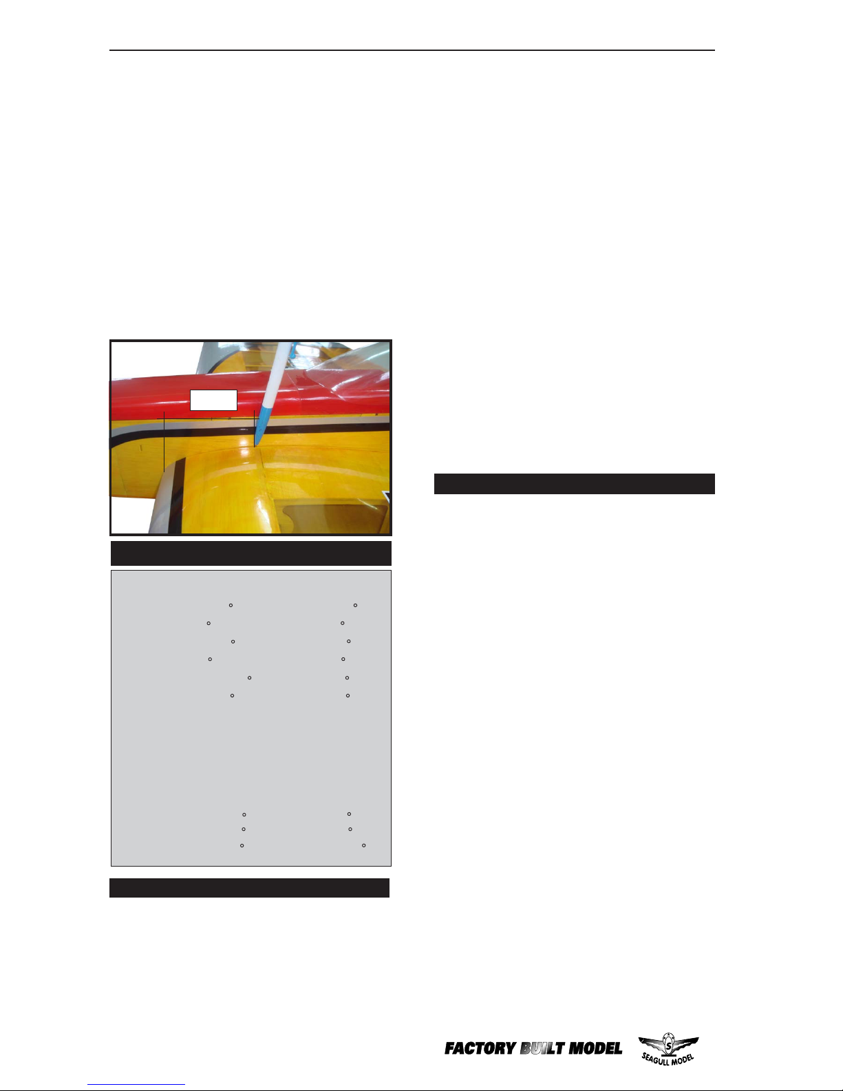
BALANCING.
1) It is critical that your airplane be
balanced correctly. Improper balance will
cause your plane to lose control and crash.
THE CENTER OF GRA VITY IS LOCATED
110 MM BACK FROM THE LEADING EDGE
OF THE WING AT THE WING ROOT.
3) Turn the airplane upside down. Place
your fingers on the masking tape and carefully
lift the plane .
2) Mount the wing to the fuselage. Using a
couple of pieces of masking tape, place them
on the top side of the wing
110 mm back from
the leading edge of the wing at the wing root.
Accurately mark the balance point on the top
of the wing on both sides of the fuselage. The
balance point is located
110 mm back from
the leading edge of the wing at the wing root.
This is the balance point at which your model
should balance for your first flights. Later , you
may wish to experiment by shifting the balance
up to 10mm forward or back to change the
flying characteristics. Moving the balance
forward may improve the smoothness and
arrow- like tracking, but it may then require
more speed for take off and make it more
difficult to slow down for landing. Moving the
balance aft makes the model more agile with
a lighter and snappier ”feel”. In any case,please
start at the location we recommend .
Insert two wing panels as pictures below.
3 x 10mm.
ATTACHMENT WING-FUSELAGE.
Wing tube.
Attach the aluminium tube into fuselage.
INSTALLING RECEIVER AND BATTERY.
Receiver.
1) Plug the five servo leads and the switch
lead into the receiver. Plug the battery pack
lead into the switch also.
3) Route the antenna in the antenna tube
inside the fuselage and secure it to the bottom of fuselage using a plastic tape.
2) Wrap the receiver and battery pack in
the protective foam rubber to protect them
from vibration.
Battery.
wing bolt.
Page 24
SEAGULL FUNFLY 3D. Instruction Manual.
24
*If possible, first attempt to balance the model
by changing the position of the receiver battery
and receiver. If you are unable to obt ain good
balance by doing so, then it will be necessary
to add weight to the nose or tail to achieve the
proper balance point.
With the wing attached to the fuselage, all
parts of the model installed ( ready to fly), and
empty fuel tanks, hold the model at the marked
balance point with the stabilizer level.
Lift the model. If the tail drops when you lift,
the model is “tail heavy” and you must add
weight* to the nose. If the nose drops, it is
“nose heavy” and you must add weight* to the
tail to balance.
CONTROL THROWS.
Aileron: 1-inch(15 )up. 1 5/8-inch(23 )up.
1-inch(15 )down. 1 5/8-inch(23 )down.
Elevator: 1-inch(14 )up. 2-inch(25 )up.
1-inch(14 )down. 2-inch(25 )down.
Rudder: 1 3/4-inch(18 )left. 2-inch(22 )left.
1 3/4-inch(18 )right. 2-inch(22 )right.
Low rate
High rate
Note: Control throws are measured at the widest
past of the elevator,rudder ,and aileron unless noted
otherwise.
Use the following throws for 3D aerobatics:
Aileron: 2 1/2-inch(35 )up 2 1/2-inch(35 )down.
Elevator: 2 3/4-inch(35 )up 2 3/4-inch(35 )down.
Rudder: 2 1/2-inch(28 )right 2 1/2-inch(28 )left.
D) Check the throttle. Moving the
throttle stick forward should open the carburetor barrel. If it does not, flip the servo reversing switch on your transmitter to change
the direction.
E) From behind the airplane, look at
the aileron on the right wing half. Move the
aileron stick to the right. The right aileron
should move up and the other aileron should
move down. If it does not, flip the servo reversing switch on your transmitter to change
the direction.
C) Check the rudder. Looking from
behind the airplane, move the rudder stick to
the right. The rudder should move to the right.
If it does not, flip the servo reversing switch on
your transmitter to change the direction.
A) Plug in your radio system per the
manufacturer's instructions and turn everything on.
Check the operation and direction of the
elevator, rudder, ailerons and throttle.
FLIGHT PREPARATION.
7) Check the receiver antenna. It should
be fully extended and not coiled up inside the
fuselage.
3) Double check the balance of the airplane. Do this with the fuel tank empty.
5) If your radio transmitter is equipped
with dual rate switches double check that they
are on the low rate setting for your first few
flights.
2) Check every bolt and every glue joint
in the SEAGULL FUNFL Y 3D to ensure that
everything is tight and well bonded.
6) Check to ensure the control surfaces
are moving the proper amount for both low
and high rate settings.
1) Completely charge your transmitter
and receiver batteries before your first day of
flying.
8) Properly balance the propeller. An out
of balance propeller will cause excessive vibration which could lead to engine and/or airframe failure.
PREFLIGHT CHECK.
B) Check the elevator first. Pull back
on the elevator stick. The elevator halves
should move up. If it they do not, flip the servo
reversing switch on your transmitter to change
the direction.
4) Check the control surfaces. All should
move in the correct direction and not bind in
any way .
We wish you many safe and enjoyable
flights with your SEAGULL FUNFLY 3D.
1 10mm.
 Loading...