

Page 1

Seagate® IronWolf® 510 SSD
100860537, Rev. A
October 2019
Product Manual
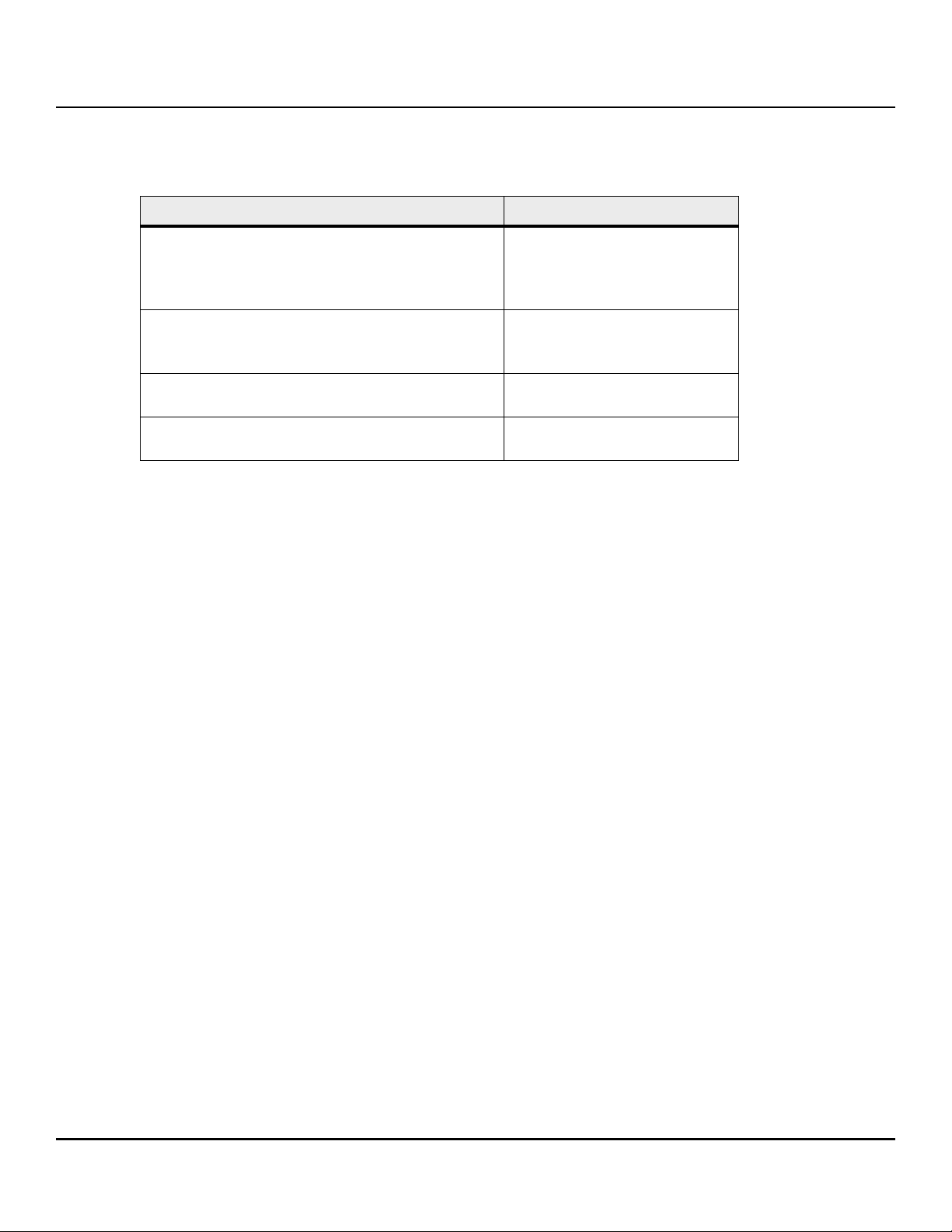
User Capacity
240 GB ZP240NM30001
480 GB ZP480NM30001
960 GB ZP960NM30001
1920 GB ZP1920NM30001
Standard
M.2 2280-S2-M
Standard
M.2 2280-D2-M
Page 2

Revision History
Version and Date Description of Changes
Rev A, October 2019 First document release.
© 2019, Seagate Technology LLC All rights reserved. Publication number: 100860537, R ev. A, October 2019.
Seagate Technology reserves the right to make changes to the product(s) or information disclosed herein at any time without notice.
Seagate, Seagate Technology and the Spiral logo are registered trademarks of Seagate Technology LLC in the United States and/or other countries. IronWolf and SeaTools are either trademarks or registered trademarks of
Seagate Technology LLC or one of its affiliated companies in the United States and/or other countries. All other tradem arks or registered trademarks are the property of their respective owners.
No part of this publication may be reproduced in any form without written permission of Seagate Technology LLC. Call 877-PUB-TEK1(877-782-8351) to request permission.
The NVMe word mark and/or NVMExpress design mark are trademarks of NVMExpress, Inc. The PCIe word mark and/or PCIExpress design mark are registered trademarks and/or ser vice marks of PCI-SIG.
When referring to drive capacity, one gigabyte, or GB, equals one billion bytes and one terabyte, or TB, equals one trillion bytes. Your computer’s operating system may use a different standard of measurement and report
a lower capacity. In addition, some of the listed capacity is used for format ting and other fun ctions, and thus w ill not be available for data storage. Actual quantities will vary based on various factors, including file size, file
format, features and application software. Actual data rates may vary depending on operating environment and other factors. The export or re-export of hardware or software containing encryption may be regulated by
the U.S. Department of Commerce, Bureau of Industry and Security (for more information, visit www.bis.doc.gov), and controlled for import and use outside of the U.S. Seagate reserves the right to change, without notice,
product offerings or specifications.
Page 3

Contents
Seagate Technology Support Services . . . . . . . . . . . . . . . . . . . . . . . . . . . . . . . . . . . . . . . . . . . . . . . . . . . . . . . . . . . . . . . . . . . . . . . . . . . . . . 5
1. Introduction . . . . . . . . . . . . . . . . . . . . . . . . . . . . . . . . . . . . . . . . . . . . . . . . . . . . . . . . . . . . . . . . . . . . . . . . . . . . . . . . . . . . . . . . . . . . . . . . . . . . 6
1.1 Reference Documents . . . . . . . . . . . . . . . . . . . . . . . . . . . . . . . . . . . . . . . . . . . . . . . . . . . . . . . . . . . . . . . . . . . . . . . . . . . . . . . . . . . . . . . . . . . . . . . . . . . . . . . . . . . . . . 7
2. Specifications . . . . . . . . . . . . . . . . . . . . . . . . . . . . . . . . . . . . . . . . . . . . . . . . . . . . . . . . . . . . . . . . . . . . . . . . . . . . . . . . . . . . . . . . . . . . . . . . . . . 8
2.1 Models and Capacity . . . . . . . . . . . . . . . . . . . . . . . . . . . . . . . . . . . . . . . . . . . . . . . . . . . . . . . . . . . . . . . . . . . . . . . . . . . . . . . . . . . . . . . . . . . . . . . . . . . . . . . . . . . . . . . . 8
2.2 Performance . . . . . . . . . . . . . . . . . . . . . . . . . . . . . . . . . . . . . . . . . . . . . . . . . . . . . . . . . . . . . . . . . . . . . . . . . . . . . . . . . . . . . . . . . . . . . . . . . . . . . . . . . . . . . . . . . . . . . . . 8
2.3 Latency . . . . . . . . . . . . . . . . . . . . . . . . . . . . . . . . . . . . . . . . . . . . . . . . . . . . . . . . . . . . . . . . . . . . . . . . . . . . . . . . . . . . . . . . . . . . . . . . . . . . . . . . . . . . . . . . . . . . . . . . . . . . 9
2.4 Quality of Service (QoS) . . . . . . . . . . . . . . . . . . . . . . . . . . . . . . . . . . . . . . . . . . . . . . . . . . . . . . . . . . . . . . . . . . . . . . . . . . . . . . . . . . . . . . . . . . . . . . . . . . . . . . . . . . . . . 9
2.5 Supply Voltage . . . . . . . . . . . . . . . . . . . . . . . . . . . . . . . . . . . . . . . . . . . . . . . . . . . . . . . . . . . . . . . . . . . . . . . . . . . . . . . . . . . . . . . . . . . . . . . . . . . . . . . . . . . . . . . . . . . . 10
2.6 Power Consumption . . . . . . . . . . . . . . . . . . . . . . . . . . . . . . . . . . . . . . . . . . . . . . . . . . . . . . . . . . . . . . . . . . . . . . . . . . . . . . . . . . . . . . . . . . . . . . . . . . . . . . . . . . . . . . . 10
2.7 Environmental Conditions . . . . . . . . . . . . . . . . . . . . . . . . . . . . . . . . . . . . . . . . . . . . . . . . . . . . . . . . . . . . . . . . . . . . . . . . . . . . . . . . . . . . . . . . . . . . . . . . . . . . . . . . . 11
2.8 Reliability and Endurance . . . . . . . . . . . . . . . . . . . . . . . . . . . . . . . . . . . . . . . . . . . . . . . . . . . . . . . . . . . . . . . . . . . . . . . . . . . . . . . . . . . . . . . . . . . . . . . . . . . . . . . . . . 12
3. Mechanical Information . . . . . . . . . . . . . . . . . . . . . . . . . . . . . . . . . . . . . . . . . . . . . . . . . . . . . . . . . . . . . . . . . . . . . . . . . . . . . . . . . . . . . . . . 13
3.1 Dimensions and Weight (M.2 2280-S2) . . . . . . . . . . . . . . . . . . . . . . . . . . . . . . . . . . . . . . . . . . . . . . . . . . . . . . . . . . . . . . . . . . . . . . . . . . . . . . . . . . . . . . . . . . . . . 13
3.2 Dimensions and Weight (M.2 2280-D2) . . . . . . . . . . . . . . . . . . . . . . . . . . . . . . . . . . . . . . . . . . . . . . . . . . . . . . . . . . . . . . . . . . . . . . . . . . . . . . . . . . . . . . . . . . . . . 15
4. Pin and Signal Descriptions . . . . . . . . . . . . . . . . . . . . . . . . . . . . . . . . . . . . . . . . . . . . . . . . . . . . . . . . . . . . . . . . . . . . . . . . . . . . . . . . . . . . . 18
5. SMART Support . . . . . . . . . . . . . . . . . . . . . . . . . . . . . . . . . . . . . . . . . . . . . . . . . . . . . . . . . . . . . . . . . . . . . . . . . . . . . . . . . . . . . . . . . . . . . . . . 21
5.1 SMART IDs . . . . . . . . . . . . . . . . . . . . . . . . . . . . . . . . . . . . . . . . . . . . . . . . . . . . . . . . . . . . . . . . . . . . . . . . . . . . . . . . . . . . . . . . . . . . . . . . . . . . . . . . . . . . . . . . . . . . . . . . . 21
6. Feature Details . . . . . . . . . . . . . . . . . . . . . . . . . . . . . . . . . . . . . . . . . . . . . . . . . . . . . . . . . . . . . . . . . . . . . . . . . . . . . . . . . . . . . . . . . . . . . . . . 22
6.1 Flash Management . . . . . . . . . . . . . . . . . . . . . . . . . . . . . . . . . . . . . . . . . . . . . . . . . . . . . . . . . . . . . . . . . . . . . . . . . . . . . . . . . . . . . . . . . . . . . . . . . . . . . . . . . . . . . . . . 22
6.1.1 Error Correction Code (ECC) . . . . . . . . . . . . . . . . . . . . . . . . . . . . . . . . . . . . . . . . . . . . . . . . . . . . . . . . . . . . . . . . . . . . . . . . . . . . . . . . . . . . . . . . . . . . . . . . . 22
6.1.2 Wear Leveling . . . . . . . . . . . . . . . . . . . . . . . . . . . . . . . . . . . . . . . . . . . . . . . . . . . . . . . . . . . . . . . . . . . . . . . . . . . . . . . . . . . . . . . . . . . . . . . . . . . . . . . . . . . . . . . 22
6.1.3 Bad Block Management . . . . . . . . . . . . . . . . . . . . . . . . . . . . . . . . . . . . . . . . . . . . . . . . . . . . . . . . . . . . . . . . . . . . . . . . . . . . . . . . . . . . . . . . . . . . . . . . . . . . . 22
6.1.4 TRIM . . . . . . . . . . . . . . . . . . . . . . . . . . . . . . . . . . . . . . . . . . . . . . . . . . . . . . . . . . . . . . . . . . . . . . . . . . . . . . . . . . . . . . . . . . . . . . . . . . . . . . . . . . . . . . . . . . . . . . . . 22
6.1.5 SMART . . . . . . . . . . . . . . . . . . . . . . . . . . . . . . . . . . . . . . . . . . . . . . . . . . . . . . . . . . . . . . . . . . . . . . . . . . . . . . . . . . . . . . . . . . . . . . . . . . . . . . . . . . . . . . . . . . . . . . 22
6.1.6 Over Provisioning . . . . . . . . . . . . . . . . . . . . . . . . . . . . . . . . . . . . . . . . . . . . . . . . . . . . . . . . . . . . . . . . . . . . . . . . . . . . . . . . . . . . . . . . . . . . . . . . . . . . . . . . . . . 23
6.1.7 Firmware Upgrade . . . . . . . . . . . . . . . . . . . . . . . . . . . . . . . . . . . . . . . . . . . . . . . . . . . . . . . . . . . . . . . . . . . . . . . . . . . . . . . . . . . . . . . . . . . . . . . . . . . . . . . . . . 23
6.1.8 Thermal Throttling . . . . . . . . . . . . . . . . . . . . . . . . . . . . . . . . . . . . . . . . . . . . . . . . . . . . . . . . . . . . . . . . . . . . . . . . . . . . . . . . . . . . . . . . . . . . . . . . . . . . . . . . . . 23
6.1.9 Multiple Namespaces . . . . . . . . . . . . . . . . . . . . . . . . . . . . . . . . . . . . . . . . . . . . . . . . . . . . . . . . . . . . . . . . . . . . . . . . . . . . . . . . . . . . . . . . . . . . . . . . . . . . . . . 23
6.1.10 Garbage Collection . . . . . . . . . . . . . . . . . . . . . . . . . . . . . . . . . . . . . . . . . . . . . . . . . . . . . . . . . . . . . . . . . . . . . . . . . . . . . . . . . . . . . . . . . . . . . . . . . . . . . . . . 23
6.2 Advanced Device Security Features . . . . . . . . . . . . . . . . . . . . . . . . . . . . . . . . . . . . . . . . . . . . . . . . . . . . . . . . . . . . . . . . . . . . . . . . . . . . . . . . . . . . . . . . . . . . . . . . 23
6.2.1 Secure Erase . . . . . . . . . . . . . . . . . . . . . . . . . . . . . . . . . . . . . . . . . . . . . . . . . . . . . . . . . . . . . . . . . . . . . . . . . . . . . . . . . . . . . . . . . . . . . . . . . . . . . . . . . . . . . . . . 23
6.2.2 Physical Presence SID . . . . . . . . . . . . . . . . . . . . . . . . . . . . . . . . . . . . . . . . . . . . . . . . . . . . . . . . . . . . . . . . . . . . . . . . . . . . . . . . . . . . . . . . . . . . . . . . . . . . . . . 23
6.2.3 Manufacturer’s Secure ID . . . . . . . . . . . . . . . . . . . . . . . . . . . . . . . . . . . . . . . . . . . . . . . . . . . . . . . . . . . . . . . . . . . . . . . . . . . . . . . . . . . . . . . . . . . . . . . . . . . . 24
6.2.4 Sanitize . . . . . . . . . . . . . . . . . . . . . . . . . . . . . . . . . . . . . . . . . . . . . . . . . . . . . . . . . . . . . . . . . . . . . . . . . . . . . . . . . . . . . . . . . . . . . . . . . . . . . . . . . . . . . . . . . . . . . 24
6.3 SSD Lifetime Management . . . . . . . . . . . . . . . . . . . . . . . . . . . . . . . . . . . . . . . . . . . . . . . . . . . . . . . . . . . . . . . . . . . . . . . . . . . . . . . . . . . . . . . . . . . . . . . . . . . . . . . . . 24
6.3.1 Media Wear Indicator . . . . . . . . . . . . . . . . . . . . . . . . . . . . . . . . . . . . . . . . . . . . . . . . . . . . . . . . . . . . . . . . . . . . . . . . . . . . . . . . . . . . . . . . . . . . . . . . . . . . . . . 25
6.3.2 Read Only Mode (End of Life) . . . . . . . . . . . . . . . . . . . . . . . . . . . . . . . . . . . . . . . . . . . . . . . . . . . . . . . . . . . . . . . . . . . . . . . . . . . . . . . . . . . . . . . . . . . . . . . . 25
6.4 Adaptive Approach to Performance Tuning . . . . . . . . . . . . . . . . . . . . . . . . . . . . . . . . . . . . . . . . . . . . . . . . . . . . . . . . . . . . . . . . . . . . . . . . . . . . . . . . . . . . . . . . 25
6.4.1 Predict and Fetch . . . . . . . . . . . . . . . . . . . . . . . . . . . . . . . . . . . . . . . . . . . . . . . . . . . . . . . . . . . . . . . . . . . . . . . . . . . . . . . . . . . . . . . . . . . . . . . . . . . . . . . . . . . 25
6.4.2 Throughput . . . . . . . . . . . . . . . . . . . . . . . . . . . . . . . . . . . . . . . . . . . . . . . . . . . . . . . . . . . . . . . . . . . . . . . . . . . . . . . . . . . . . . . . . . . . . . . . . . . . . . . . . . . . . . . . . 25
Seagate IronWolf 510 SSD Product Manual, Rev A 3
Page 4

Contents
7. Safety Certifications, and Compliance . . . . . . . . . . . . . . . . . . . . . . . . . . . . . . . . . . . . . . . . . . . . . . . . . . . . . . . . . . . . . . . . . . . . . . . . . . . 26
7.1 Regulatory Model Numbers . . . . . . . . . . . . . . . . . . . . . . . . . . . . . . . . . . . . . . . . . . . . . . . . . . . . . . . . . . . . . . . . . . . . . . . . . . . . . . . . . . . . . . . . . . . . . . . . . . . . . . . . 26
Seagate IronWolf 510 SSD Product Manual, Rev A 4
Page 5

Seagate Technology Support Services
For Internal SSD Support, visit: https://www.seagate.com/support/products/
For Firmware Download and Tools Download for Secure Erase, visit: https://www.seagate.com/support/downloads/
For information regarding online support and services, visit: http://www.seagate.com/contacts/
For information regarding Warranty Support, visit: http://www.seagate.com/support/warranty-and-replacements/
For information regarding data recovery services, visit:
http://www.seagate.com/services-software/seagate-recovery-services/recover/
For Seagate OEM and Distribution partner and Seagate reseller portal, visit: http://www.seagate.com/partners
Seagate IronWolf 510 SSD Product Manual, Rev A 5
Page 6
www.seagate.com
1. Introduction
The Seagate® IronWolf® 510 SSD is designed for everything business NAS, with 24×7 perf ormance to handle
multi-user environments across a wide range of capacities. The Seagate IronWolf 510 SSD offers PCIe Gen 3 x4
interface with NVMe protocol support in an ultra-small M.2 form factor.
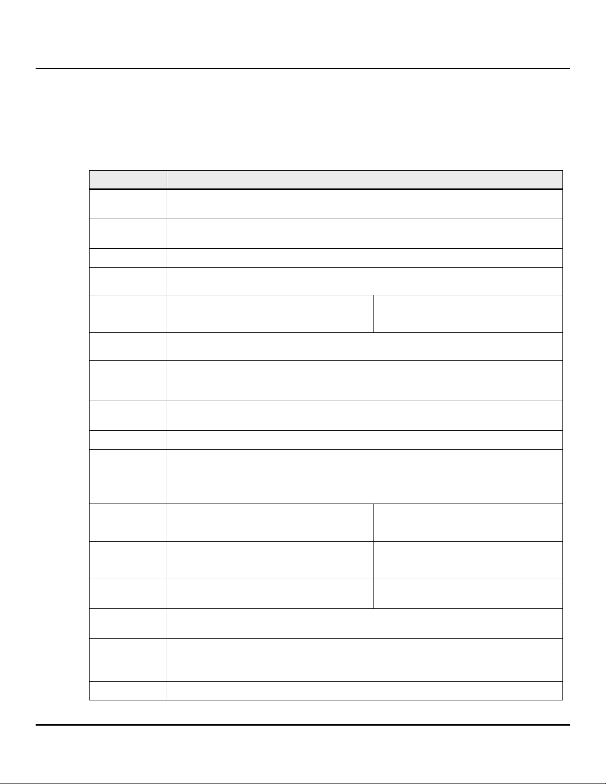
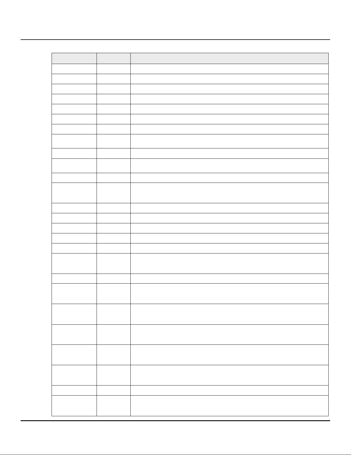
Table 1 The IronWolf 510 SSD Features
Feature Description
Capacity
(User)
Certifications,
Eco-Compliance
Data Retention
Dimensions
Endurance
Form Factor
Interface
Compliance
Logical Block
Size
NAND
240 GB, 480 GB, 960 GB, 1920 GB
CE, UL, FCC, BSMI, KCC, Microsoft WHQL, VCCI, CB
RoHS
12 months power-off retention at 30°C per JEDEC client standard
M.2 2280-S2 (240 GB, 480 GB): 80 mm (±0.15) x 22 mm (±0.15) x 2.15 mm (±0.15)
M.2280-D2 (960 GB, 1920 GB): 80 mm (+ - 0.15) x 22 mm (+ - 0.15) x 3.5 mm (+ - 0.08)
1 Drive Write Per Day (DWPD) Endurance rating valid for SSD Life Remaining >
1% (SMART E7h>1).
See Section 2.8, Reliability and Endurance.
M.2 2280-S2-M (240 GB, 480 GB)
M.2 2280-D2-M (960 GB, 1920 GB)
PCIe Gen3 x4, backwards compatible with PCIe Gen2 and Gen1
NVMe 1.3 compliant
8 IO queues supported (1 admin queue and 8 IO queue). Each IO queue support 256 entries
512 bytes (default)
4KB
3D TLC
Operating
Systems
Performance
Random
Windows® 8.1 (64 bit), and Windows 10 (64 bit), Windows Enterprise 10, Windows Server 2016, 2019
Ubuntu 16.04,18.04
CentOS 6 and 7
RHEL 7
Read: Up to 380,000 IOPS
Write: Up to 29,000 IOPS
Actual performance might vary depending on
use conditions and environment.
See Section 2.2, Performance.
Performance
Sequential
Read: Up to 3150MB/s
Write: Up to 1000MB/s
Actual performance might vary depending on
the capacity, use conditions and environment.
See Section 2.2, Performance.
Power
Consumption
Power
Active mode: < 6000 mW
Idle mode: < 2000 mW
Supports Active State Power Management (ASPM)
Results vary with capacity and mode.
See Section 2.6, Power Consumption.
Management
Reliability
Security
End-to-end data path protection
MTBF: 1.8 million hours
UBER: 1 error in 10
TCG Pyrite supported on standard models
16
bits read
Seagate IronWolf 510 SSD Product Manual, Rev A 6
Page 7
www.seagate.com
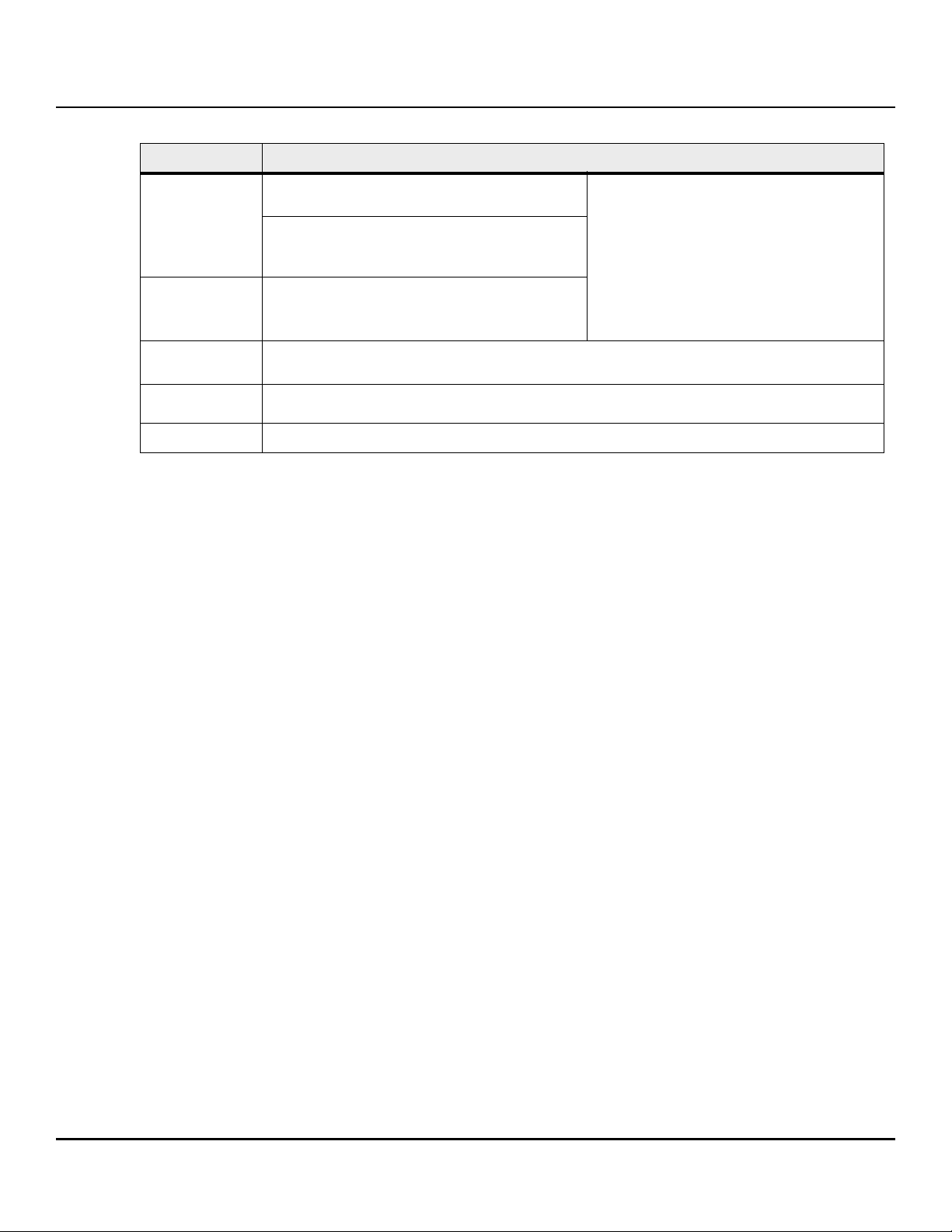
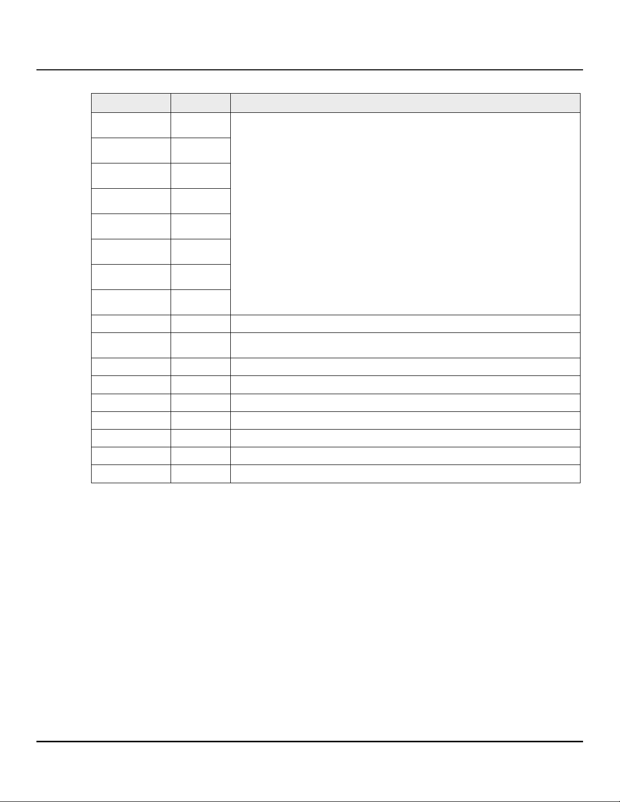
Table 1 The IronWolf 510 SSD Features (continued)
Feature Description
Shock and
Vibration
Shock
Non-Operating: 1,500 G, at 0.5 ms
Vibration
Non-Operating: 1.52 G
Frequency)
Temperature
Range
0°C to 70°C
Temperature Sensor (SMART Attribute ID C2h)
(Operating)
Voltage
Warran ty
Min = 3.14V
Max = 3.47 V
Five years, or when the device reaches Host TBW, whichever happens first. Endurance rating valid for SSD
Life Remaining > 1% (SMART E7h>1).
Weight
6.5 to 8.3g ±5%
1.1 Reference Documents
, (20 to 800 Hz,
RMS
See Section 2.7, Environmental
Conditions.
In case of conflict between this document and the following reference document, this document takes precedence.
PCIe Specifications
— PCIe - PCI Express Electromechanical specification, revision 4.0
— NVMe - Non Volatile Memory Express specification 1.3
— PCIe CEM - PCI Express Card Electromechanical specification, revision 1.1
— PCI Express M.2 Specification, revision 1.1
Trusted Computing Group (TCG) Documents
— Storage Work Group Security Subsystem Class: Opal, Version 2.00
Solid State Drive Requirements and Endurance Test Methods
— JESD218
— JESD219
Seagate Documentation
— SeaTools™ SSD GUI User Guide - Publication Number: 100837824
— SeaChest for SSD User Guide - Publication Number: 100847684
Seagate IronWolf 510 SSD Product Manual, Rev A 7
Page 8
www.seagate.com
2. Specifications
2.1 Models and Capacity
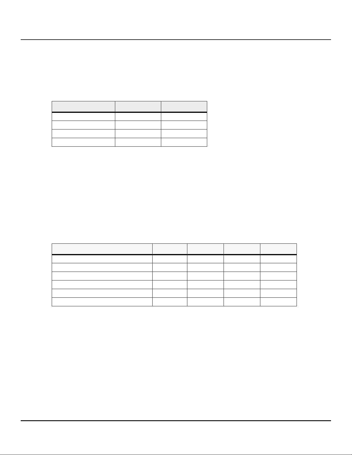
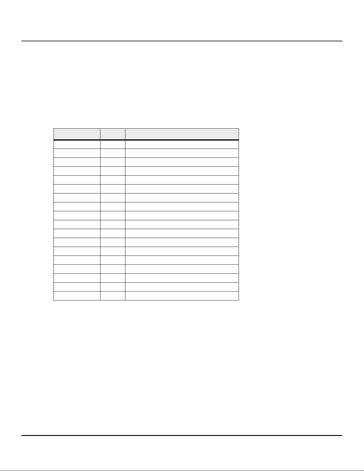
Table 2 Models and Capacity
Model Names User Capacity NAND
ZP240NM30001 240 GB 3D TLC
ZP480NM30001 480 GB 3D TLC
ZP960NM30001 960 GB 3D TLC
ZP1920NM3001 1920 GB 3D TLC
NOTE About capacity:
Sector Size: 512 Bytes (default), and 4000 Bytes
User-addressable LBA count = (97696368) + (1953504 x (Desired Capacity
in Gb-50.0)) From International Disk Drive Equipment and Materials
Association (IDEMA) (LBA1-03_standard.doc)
2.2 Performance
Table 3 Random and Sequential Read and Write Performance
Parameter 240 GB 480 GB 960 GB 1920 GB
Sequential Read (MB/s) 2,450 2,650 3,150 3,150
Sequential Write (MB/s) 290 600 1,000 850
Random Read (IOPS) (QD32T4) 100,000 193,000 345,000 270,000
Random Write (IOPS) (QD32T4) 12,000 20,000 28,000 25,000
Random Read (IOPS) (QD32T8) 100,000 199,000 380,000 290,000
Random Write (IOPS) (QD32T8) 13,000 21,000 29,000 27,000
NOTE About performance:
Performance can vary based on the SSD’s firmware version, system
hardware, and configuration.
Performance is measured with the following conditions
(a) Sustained Sequential: FIO, full-range, 128K data size, QD=32
(b) Sustained Random: FIO, full-range, 4K data size, QD=32, 4/8 workers
Seagate IronWolf 510 SSD Product Manual, Rev A 8
Page 9
www.seagate.com
2.3 Latency
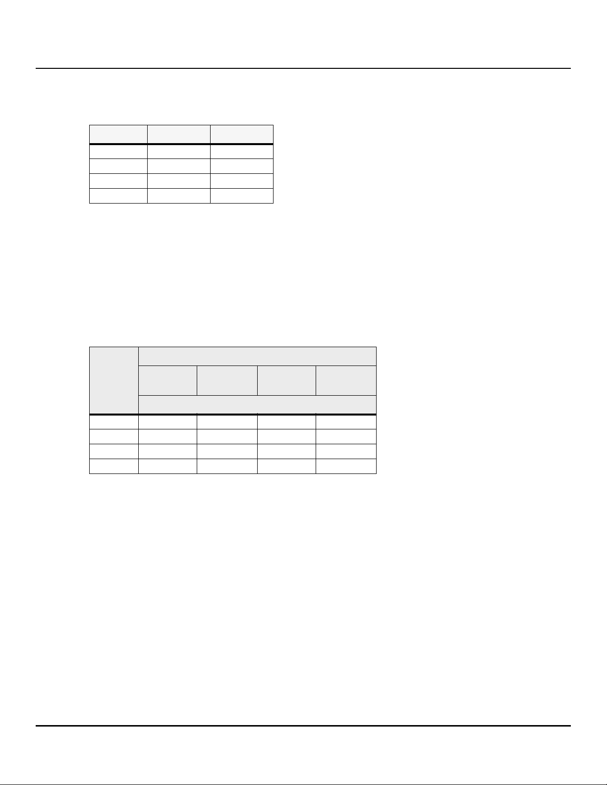
Table 4 QD1 4KB Random Average Latency
Capacity Read (4KB) Write (4KB)
240 GB 110 70
480 GB 110 40
960 GB 110 30
1920 GB 140 30
NOTE About latency:
Performance can differ according to flash configuration and platform.
The latency table is for reference only. Units are in microseconds.
2.4 Quality of Service (QoS)
Table 5 Quality of Service (QoS)
QoS (99.99%)
Capacity
240 GB 0.34 0.13 1.67 2.53
480 GB 0.32 0.10 0.99 1.64
960 GB 0.34 0.11 0.62 1.51
1920 GB 0.44 0.10 0.83 1.63
Read
(4KB QD=1)
Write
(4KB QD=1)
Unit: ms
Read
(4KB QD=32)
Write
(4KB QD=32)
NOTE About QoS:
QoS is measured with the following conditions
FIO test: 4KB transfer size, QD=1 or 32 on 4KB random read and write
workload on whole LBA range of SSD when the performance performs on
steady state and all background operations run normally.
According to random 4KB QD=1 and 32 workloads, the result of QoS is the
maximum round-trip time which is taken for 99.99% of commands to
host.
QoS can differ according to flash configuration and platform.
Seagate IronWolf 510 SSD Product Manual, Rev A 9
Page 10

www.seagate.com
2.5 Supply Voltage
Table 6 Supply Voltage
Parameter Rating
Operating Voltage
Rise Time (Max/Min)
Fall Time (Max/Min)
Minimum Off Time
Min = 3.14V
Max = 3.47 V
100 ms / 0.1 ms
5 s /1 ms
1 s
NOTE Minimum Off Time is the time between power being removed from the SSD
(Vcc<100 mW) and power being re-applied to the SSD.
2.6 Power Consumption
Table 7 Power Consumption
Max Average Active (mW) 5,300 6,000 6,000 6,000
Peak Active (mW) 5,500 6,200 6,200 6,500
Idle (mW) 1,750 1,830 1,950 2,000
NOTE About power consumption:
240 GB 480 GB 960 GB 1920 GB
The measured power voltage is 3.3 V.
Power consumption is measured during the sequential/random read and
write performed by FIO 3.7.
Power Consumption can differ according to flash configuration and
platform.
Seagate IronWolf 510 SSD Product Manual, Rev A 10
Page 11
www.seagate.com
2.7 Environmental Conditions
Table 8 Temperature, Humidity, Shock
Specification Value
Temperature
Operational temperature
(with airflow: 800 LFM at 35°C )
Non-operating
Humidity
Operating
Non-operating (storage)
Shock
Non-operating
Vibration
Non-operating
NOTE Temperature is measured without condensation.
Operating mode temperature is measured by temperature sensor, SMART
Attribute C2h.
0°C to 70°C
-40°C to 85°C
1,500 G, duration 0.5 ms
1.52 G
(20Hz to 80Hz, Frequency)
RMS,
90%
93%
Airflow is suggested. Airflow allows the device to be operated at the
appropriate temperature for each component during heavy workloads
environments.
NOTE Shock and vibration results assume that the SSD is mounted securely with the
input vibration applied to the SSD mounting. These specifications do not cover
connection issues that may result from testing at this level. The measured
specification is in root mean square (RMS) form.
Non-operating Shock. The limits of non-operating shock applies to all
conditions of handling and transportation. This includes both isolated
SSD and integrated SSDs. Shock may be applied in the X, Y, or Z-axis.
Non-Operating Vibration. The limits of non-operating vibration shall
apply to all conditions of handling and transportation. This includes both
isolated SSD and integrated SSDs. Vibration may be applied in the X, Y, or
Z-axis.
Seagate IronWolf 510 SSD Product Manual, Rev A 11
Page 12

www.seagate.com
2.8 Reliability and Endurance
Table 9 Reliability and Endurance
Specification Valu e
Mean time between failures (MTBF) 1.8 million hours
Bit Error Rate
Endurance 240 GB: 1 DWPD
NOTE About endurance:
The SSD achieves the specified MTBF in an operational environment that
complies with the operational temperature range specified in this manual.
Operating temperatures are measured by temperature sensor, SMART
Attribute ID C2h.
Endurance rating valid for SSD Life Remaining > 1% (SMART E7h>1).
Endurance is characterized while running Client JESD219A workload (per
JESD218A specification).
1 error in 10
480 GB: 1 DWPD
960 GB: 1 DWPD
1,920 GB: 1 DWPD
16
bits read
Seagate IronWolf 510 SSD Product Manual, Rev A 12
Page 13

www.seagate.com
3. Mechanical Information
3.1 Dimensions and Weight (M.2 2280-S2)
Weight: 6.5 g (240 GB), 6.9 g (480 GB)
Height: 2.15 mm±008 mm
Width: 22 mm±0.15 mm
Length: 80 mm±-0.15 mm
Figure 1 Top View
Seagate IronWolf 510 SSD Product Manual, Rev A 13
Page 14

www.seagate.com
Figure 2 Bottom View
Figure 3 Side View
Seagate IronWolf 510 SSD Product Manual, Rev A 14
Page 15

www.seagate.com
3.2 Dimensions and Weight (M.2 2280-D2)
Weight: 8.1 g (960 GB), 8.3 g (1920 GB)
Height: 3.5 mm±0.08 mm
Width: 22 mm±0.15 mm
Length: 80 mm±0.15 mm
Figure 4 Top View
Seagate IronWolf 510 SSD Product Manual, Rev A 15
Page 16

www.seagate.com
Figure 5 Bottom View
Seagate IronWolf 510 SSD Product Manual, Rev A 16
Page 17

www.seagate.com
Figure 6 Side View
Seagate IronWolf 510 SSD Product Manual, Rev A 17
Page 18

www.seagate.com
4. Pin and Signal Descriptions
Table 10 Pin Descriptions
Pin No PCIe Pin Description
1 GND CONFIG_3=GND
23.3V
3GND
43.3V
5PETn3
6N/C
7PETp3
8N/C
9GND
10 LED1#
3.3V source
Ground
3.3V source
PCIe TX Differential signal defined by the PCI Express M.2 spec
No connect
PCIe TX Differential signal defined by the PCI Express M.2 spec
No connect
Ground
Open drain, active low signal. These signals are used to allow the add- in card to provide status
indicators via LED devices that will be provided by the system.
11 PERn3
12 3.3V
13 PERp3
14 3.3V
15 GND
16 3.3V
17 PETn2
18 3.3V
19 PETp2
20 N/C
21 GND
22 N/C
23 PERn2
24 N/C
25 PERp2
26 N/C
27 GND
28 N/C
29 PETn1
30 N/C
31 PETp1
32 N/C
PCIe RX Differential signal defined by the PCI Express M.2 spec
3.3V source
PCIe RX Differential signal defined by the PCI Express M.2 spec
3.3V source
Ground
3.3V source
PCIe TX Differential signal defined by the PCI Express M.2 spec
3.3V source
PCIe TX Differential signal defined by the PCI Express M.2 spec
No connect
Ground
No connect
PCIe RX Differential signal defined by the PCI Express M.2 spec
No connect
PCIe RX Differential signal defined by the PCI Express M.2 spec
No connect
Ground
No connect
PCIe TX Differential signal defined by the PCI Express M.2 spec
No connect
PCIe TX Differential signal defined by the PCI Express M.2 spec
No connect
Seagate IronWolf 510 SSD Product Manual, Rev A 18
Page 19
www.seagate.com
Table 10 Pin Descriptions (continued)
Pin No PCIe Pin Description
33 GND
34 N/C
35 PERn1
36 N/C
37 PERp1
38 N/C
39 GND
40
41 PETn0
42
43 PETp0
44
SMB_CLK
(I/O)(0/1.8V)
SMB_DATA
(I/O)(0/1.8V)
ALERT#(O)
(0/1.8V)
Ground
No connect
PCIe RX Differential signal defined by the PCI Express M.2 spec
No connect
PCIe RX Differential signal defined by the PCI Express M.2 spec
No connect
Ground
SMBus Clock; Open Drain with pull-up on platform
PCIe TX Differential signal defined by the PCI Express M.2 spec
SMBus Data; Open Drain with pull-up on platform.
PCIe TX Differential signal defined by the PCI Express M.2 spec
Alert notification to master; Open Drain with pull-up on platform; Active low.
45 GND
46 N/C
47 PERn0
48 N/C
49 PERp0
50
51 GND
52
53 REFCLKn
54
55 REFCLKp
56
PERST#(I)(0/3.
3V)
CLKREQ#(I/O)
(0/3.3V)
PEWAKE#(I/O)
(0/3.3V)
Reserved for
MFG DATA
Ground
No connect
PCIe RX Differential signal defined by the PCI Express M.2 spec
No connect
PCIe RX Differential signal defined by the PCI Express M.2 spec
PE-Reset is a functional reset to the card as defined by the PCIe Mini CEM specification.
Ground
Clock Request is a reference clock request signal as defined by the PCIe M ini CEM specification;
Also used by L1 PM Sub-st ates.
PCIe Reference Clock signals (100 MHz) defined by the PCI Express M.2 spec.
PCIe PME Wake.
Open Drain with pull up on platform; Active Low.
PCIe Reference Clock signals (100 MHz) defined by the PCI Express M.2 spec.
Manufacturing Data line. Used for SSD manufacturing only. Not used in normal operation.
platform Socket.
57 GND
58
Seagate IronWolf 510 SSD Product Manual, Rev A 19
Reserved for
MFG CLOCK
Ground
Manufacturing Clock line. Used for SSD manufacturing only.
Not used in normal operation.
Pins should be left N/C in platform Socket.
Page 20
www.seagate.com
Table 10 Pin Descriptions (continued)
Pin No PCIe Pin Description
59
60
61
62
63
64
65
66
67 N/C
68
69 N/C
70 3.3V
71 GND
72 3.3V
73 GND
74 3.3V
75 GNDZD
Module Key
M
Module Key
M
Module Key
M
Module Key
M
Module Key
M
Module Key
M
Module Key
M
Module Key
M
SUSCLK(32KH
z) (I)(0/3.3V)
Module Key
No connect
32.768 kHz clock supply input that is provided by the platform chipset to reduce power and
cost for the module.
PEDET (NC-PCIe)
3.3V source
Ground
3.3V source
Ground
3.3V source
Ground
Seagate IronWolf 510 SSD Product Manual, Rev A 20
Page 21
www.seagate.com
5. SMART Support
The IronWolf 510 SSD supports the SMART command set.
5.1 SMART IDs
The following table lists SMART IDs and Descriptions.
Table 11 SMART IDs
Bytes Index Bytes Description
[0] 1 Critical Warning
[2:1] 2 Composite Temperature
[3] 1 Available Spare
[4] 1 Available Spare Threshold
[5] 1 Percentage Used
[31:6] 26 Reserved
[47:32] 16 Data Units Read
[63:48] 16 Data Units Written
[79:64] 16 Host Read Commands
[95:80] 16 Host Write Commands
[111:96] 16 Controller Busy Time
[127:112] 16 Power Cycles
[143:128] 16 Power On Hours
[159:144] 16 Unsafe Shutdowns
[175:160] 16 Media and Data Integrity Errors
[191:176] 16 Number of Error Information Log Entries
[195:192] 4 Warning Composite Temperature Time
[199:196] 4 Critical Composite Temperature Time
Seagate IronWolf 510 SSD Product Manual, Rev A 21
Page 22

www.seagate.com
6. Feature Details
6.1 Flash Management
6.1.1 Error Correction Code (ECC)
Flash memory cells deteriorate with use. This can generate random bit errors in the stored data. The IronWolf 510 SSD
applies the LDPC ECC algorithm to detect and correct 340bits/2K Byte errors occur during read process, to make sure
the SSD reads correctly, and to protect data from corruption.
6.1.2 Wear Leveling
NAND flash devices can undergo only a limited number of program/erase cycles. Commonly, the SSD does not use
areas of the flash media evenly. If the SSD updates some areas more frequently than others, this reduces the lifetime of
the device. Wear Leveling extends the life of the NAND Flash by evenly distributing write and erase cycles across the
media.
Seagate’s advanced Wear Leveling algorithm spreads the flash usage throughout the whole flash media area.
Implementing dynamic and static Wear Leveling algorithms improves the life expectancy of the NAND flash.
6.1.3 Bad Block Management
Bad blocks do not function properly and they can contain more invalid bits. This can make stored data unstable and
bad block reliability is not guaranteed. Blocks identified and marked as bad by the manufacturer are called “Early Bad
Blocks”. Bad blocks that develop during the lifespan of the Flash are called “Later Bad Blocks”. Seagate’s bad block
management algorithm detects the factory-produced bad blocks and manages bad blocks that appear with use. This
practice prevents the drive from storing data in bad blocks and improves data reliability
6.1.4 TRIM
The TRIM feature improves the read/write performance and speed of SSDs. SSDs cannot overwrite existing data, so
the available space becomes smaller with each data block use. The TRIM command tells the SSD [through the
operating system] which data blocks can be removed permanently because they are no longer in use. The SSD erases
these unused data blocks.
6.1.5 SMART
SMART, stands for Self-Monitoring, Analysis, and Reporting Technology. SMART is an open standard that allows an SSD
to automatically detect its health and report potential failures. When SMART records a failure, users can replace the
SSD to prevent unexpected outage or data loss. SMART can also inform users of impending failures while there is still
time to copy data to another device.
Seagate IronWolf 510 SSD Product Manual, Rev A 22
Page 23

www.seagate.com
6.1.6 Over Provisioning
Over Provisioning (OP) preserves an additional area beyond user capacity in an SSD, which is not visible to users and
cannot be used by them. OP improves performance and IOPS (Input/Output Operations per Second) by providing the
controller additional space to manage P/E cycles. OP enhances the reliability and endurance as well. Moreover, the
write amplification of the SSD becomes lower when the controller writes data to the flash.
6.1.7 Firmware Upgrade
Firmware provides a set of instructions on how the device communicates with the host. Upgrade firmware when you
add features, fix compatibility issues, or after improvement of read/write performance.
6.1.8 Thermal Throttling
Thermal throttling prevents components in an SSD from over-heating during read and write operations. The IronWolf
510 SSD design provides an on-die and onboard thermal sensor. With this accuracy, firmware can apply different
levels of throttling to protect efficiently and proactively through the SMART 12 reading.
6.1.9 Multiple Namespaces
An NVMe namespace is a quantity of non-volatile memory (NVM) You can format this namespace into logical blocks.
You can use namespaces when you configure a storage virtual machine with the NVMe protocol.
You can support up to four namespaces for greater deployment flexibility.
6.1.10 Garbage Collection
Garbage collection allocates and releases memory to accelerate the read/write processing and improve performance.
When there is less available space, the SSD slows down the read/write processing and implements garbage collection
to release memory.
6.2 Advanced Device Security Features
6.2.1 Secure Erase
Secure Erase is a standard NVMe format command and it writes all of “0xFF” to fully wipe all the data on hard drives
and SSDs. When this command issues, the SSD controller erases its storage blocks and returns to its factory default
settings.
6.2.2 Physical Presence SID
The Physical Presence SID (PSID) is defined as a 32-character string. PSID reverses the SSD to its manufacturing setting
when the SSD is set through TCG Pyrite (non-SED). The PSID code is printed on the SSD label. PSID erases all data when
reverting the SSD to manufacturing settings.
Seagate IronWolf 510 SSD Product Manual, Rev A 23
Page 24
www.seagate.com
6.2.3 Manufacturer’s Secure ID
The Manufacturer’s Secure ID (MSID) is defined as a 32-character string and is assigned in the manufacturing process.
You cannot change this data through the host system. You can retrieve MSID electronically from the SSD across the
interface. After getting the SSD, you must set a new password. If you do not set a new password, anyone who can reset
the MSID can control the SSD. Such an attack on the SSD is called Denial of Service (DoS) because the rightful owner is
locked out.
6.2.4 Sanitize
The Sanitize feature uses the Format NVM command to provide an alternative to the existing secure erase capabilities.
This feature provides robust data security by making sure the user data from the SSD media, caches, and the
Controller Memory Buffer are erased by the block erase operations, overwriting or destroying the encryption key. The
following table shows the types of Sanitize Operations supported.
Table 12 Sanitize Operations
SSD Security Type
Overwrite Block Erase
Non-SED (TCG Pyrite) Yes Yes No Yes No
Sanitize Operation TCG Commands
Crypto
Erase
PSID Revert
Process
Instant Security
Erase
NOTE Crypto Erase erases all the data of the AES-encrypted data structure by
resetting the cryptographic key of the disk. The previously encrypted data
becomes nonrecoverable.
Instant Security Erase erases all the data of the SED SSD with the
Opal-activated encrypted data structure by resetting the SSD with the PSID.
Because the key resets, you cannot access the previously encrypted data.
6.3 SSD Lifetime Management
Drive Writes per Day (DWPD) The Terabytes Written (TBW) specification of an SSD calculates how many times you
can write the user capacity of an SSD per day over the warranty period (or a different number of years), based on the
JEDEC workload used to specify the TBW.
DWPD = (TBW of an SSD x 1024) / (Warranty days x SSD size in GB)
TBW (Terabytes Written) measures the lifespan of the SSD. This measurement represents the amount of data written
to the device. To calculate the TBW of an SSD, use the following equation:
TBW = [(NAND Endurance) x (SSD Capacity)] / [ WAF]
NAND Endurance: NAND endurance refers to the P/E (Program/Erase) cycle of a NAND flash.
SSD Capacity: The SSD capacity is the specific capacity in total of an SSD.
WAF: Write Amplification Factor (WAF) is a numerical value. This value represents the ratio between the amount of
data that an SSD controller needs to write and the amount of data that the host’s flash controller writes. A WAF, near 1,
guarantees better endurance and lower frequency of data written to flash memory.
TBW in this document is based on the JEDEC 218/219 workload.
Seagate IronWolf 510 SSD Product Manual, Rev A 24
Page 25

www.seagate.com
6.3.1 Media Wear Indicator
The SMART attribute byte index [5], Percentage Used, reports the Actual Life Indicator. Replace the SSD when this
number reaches 100%.
6.3.2 Read Only Mode (End of Life)
When program/erase cycles age the SSD, media wear-out can cause increasing numbers of bad blocks. When the
number of usable good blocks is less than the threshold (5%, SMART attribute log ID 02h Byte4), the SSD notifies the
host through an AER event and Critical Warning to enter Read Only Mode to prevent further data corruption. When
this happens, replace the SSD immediately.
6.4 Adaptive Approach to Performance Tuning
6.4.1 Predict and Fetch
When the Host tries to read data from the SSD, the SSD performs only one read action after receiving one command.
However, the IronWolf 510 SSD applies Predict and Fetch to improve the read speed. When the host issues sequential
read commands to the SSD, the SSD expects that the following are also read commands. Therefore, before receiving
the next command, flash has prepared the data. This accelerates data processing time, and the host needs less wait
time to receive data.
6.4.2 Throughput
Based on the available space of the SSD, the IronWolf 510 SSD regulates the read/write speed and manages the
performance of throughput. When the SSD has more space, the firmware continuously performs read/write actions.
When the SSD has less available space, it slows down the read/write processing and implements garbage collection to
release memory.
Seagate IronWolf 510 SSD Product Manual, Rev A 25
Page 26

www.seagate.com
7. Safety Certifications, and Compliance
You can find up to date information on safety certifications, and component compliance requirements for Seagate
devices on the Seagate Support page, here:
For a direct link to the Seagate HDD and SSD Regulatory Compliance and Safety document, go here:
https://www.seagate.com/files/www-content/forms/compliance/regulatory-compliance-and-safety-100838899-A.pdf
7.1 Regulatory Model Numbers
The following regulatory model number represents all features and configurations in the SeagateIronWolf 510 SSD
series:
STA015 (M.2 2280-S2) and STA016 (M2. 2280-D2)
https://www.seagate.com/support/
Seagate IronWolf 510 SSD Product Manual, Rev A 26
Page 27

Seagate Technology LLC
AMERICAS Seagate Technology LLC 10200 South De Anza Boulevard, Cupertino, California 95014, United States, 408-658-1000
ASIA/PACIFIC Seagate Singapore International Headquarters Pte. Ltd. 7000 Ang Mo Kio Avenue 5, Singapore 569877, 65-6485-3888
EUROPE, MIDDLE EAST AND AFRICA Seagate Technology Netherlands BV, Tupolevlaan, 105, 119 PA Schipol-Rijk. the Netherlands
Publication Number: 100860537, Rev. A
October, 2019
 Loading...