

Page 1

Seagate® Nytro® XF1230 SATA SSD
Product Manual
XF1230-1A0240
XF1230-1A0480
XF1230-1A0960
XF1230-1A1920
100797573, Rev. B
April 2016
Page 2
Revision History
Version and Date Description of Changes
Rev B, April, 2016 Updated the following:
Cover page, model number.
Section 2.1, Models and Capacity, Tabl e 2, model number.
Section 2.2, Performance., added Sequential Read, Sequential Write specifications. Updated Random
Write 8 K specification for 480 GB.
Rev A, March 2016 First release of the document.
© 2016, Seagate Technology LLC All rights reserved. Publication number: 100797573, Rev. B, April 2016
Seagate Technology reserves the right to make changes to the product(s) or information disclosed herein at any time without notice.
Seagate, Seagate Technology and the Spiral logo are registered trademarks of Seagate Technology LLC in the United States and/or other countries. Nytro, Nytro WarpDrive and SeaTools are either trademarks or registered
trademarks of Seagate Technology LLC or one of its affiliated companies in the United States and/or other countries. All other trademarks or registered trademarks are the property of their respective owners.
No part of this publication may be reproduced in any form without written permission of Seagate Technology LLC. Call 877-PUB-TEK1(877-782-8351) to request permission.
When referring to drive capacity, one gigabyte, or GB, equals one billion bytes and one terabyte, or TB, equals one trillion bytes. Your computer’s operating system may use a different standard of measurement and report
a lower capacity. In addition, some of the listed capacity is used for formatti ng and other funct ions, and thus wil l not be available for data storage. Actual quantities will vary based on various factors, including file size, file
format, features and application software. Actual data rates may vary depending on operating environment and other factors. The export or re-export of hardware or software containing encryption may be regulated by
the U.S. Department of Commerce, Bureau of Industry and Security (for more information, visit www.bis.doc.gov), and controlled for import and use outside of the U.S. Seagate reserves the right to change, without notice,
product offerings or specifications.
Page 3

Contents
Seagate Technology Support Services . . . . . . . . . . . . . . . . . . . . . . . . . . . . . . . . . . . . . . . . . . . . . . . . . . . . . . . . . . . . . . . . . . . . . . . . . . . . . . 4
1. Introduction . . . . . . . . . . . . . . . . . . . . . . . . . . . . . . . . . . . . . . . . . . . . . . . . . . . . . . . . . . . . . . . . . . . . . . . . . . . . . . . . . . . . . . . . . . . . . . . . . . . . 5
2. Specifications . . . . . . . . . . . . . . . . . . . . . . . . . . . . . . . . . . . . . . . . . . . . . . . . . . . . . . . . . . . . . . . . . . . . . . . . . . . . . . . . . . . . . . . . . . . . . . . . . . . 7
2.1 Models and Capacity . . . . . . . . . . . . . . . . . . . . . . . . . . . . . . . . . . . . . . . . . . . . . . . . . . . . . . . . . . . . . . . . . . . . . . . . . . . . . . . . . . . . . . . . . . . . . . . . . . . . . . . . . . . . . . . . 7
2.2 Performance . . . . . . . . . . . . . . . . . . . . . . . . . . . . . . . . . . . . . . . . . . . . . . . . . . . . . . . . . . . . . . . . . . . . . . . . . . . . . . . . . . . . . . . . . . . . . . . . . . . . . . . . . . . . . . . . . . . . . . . 7
2.3 Power Consumption . . . . . . . . . . . . . . . . . . . . . . . . . . . . . . . . . . . . . . . . . . . . . . . . . . . . . . . . . . . . . . . . . . . . . . . . . . . . . . . . . . . . . . . . . . . . . . . . . . . . . . . . . . . . . . . . 8
2.3.1 Operating Power Environmental Conditions . . . . . . . . . . . . . . . . . . . . . . . . . . . . . . . . . . . . . . . . . . . . . . . . . . . . . . . . . . . . . . . . . . . . . . . . . . . . . . . . . . 8
2.4 Reliability . . . . . . . . . . . . . . . . . . . . . . . . . . . . . . . . . . . . . . . . . . . . . . . . . . . . . . . . . . . . . . . . . . . . . . . . . . . . . . . . . . . . . . . . . . . . . . . . . . . . . . . . . . . . . . . . . . . . . . . . . . 9
2.5 Endurance . . . . . . . . . . . . . . . . . . . . . . . . . . . . . . . . . . . . . . . . . . . . . . . . . . . . . . . . . . . . . . . . . . . . . . . . . . . . . . . . . . . . . . . . . . . . . . . . . . . . . . . . . . . . . . . . . . . . . . . . . . 9
3. Mechanical Information . . . . . . . . . . . . . . . . . . . . . . . . . . . . . . . . . . . . . . . . . . . . . . . . . . . . . . . . . . . . . . . . . . . . . . . . . . . . . . . . . . . . . . . . 10
3.1 Dimensions and Weight . . . . . . . . . . . . . . . . . . . . . . . . . . . . . . . . . . . . . . . . . . . . . . . . . . . . . . . . . . . . . . . . . . . . . . . . . . . . . . . . . . . . . . . . . . . . . . . . . . . . . . . . . . . 10
4. Pin and Signal Descriptions . . . . . . . . . . . . . . . . . . . . . . . . . . . . . . . . . . . . . . . . . . . . . . . . . . . . . . . . . . . . . . . . . . . . . . . . . . . . . . . . . . . . . 11
4.1 Serial ATA Interface Connector . . . . . . . . . . . . . . . . . . . . . . . . . . . . . . . . . . . . . . . . . . . . . . . . . . . . . . . . . . . . . . . . . . . . . . . . . . . . . . . . . . . . . . . . . . . . . . . . . . . . . 11
4.2 Pin Locations . . . . . . . . . . . . . . . . . . . . . . . . . . . . . . . . . . . . . . . . . . . . . . . . . . . . . . . . . . . . . . . . . . . . . . . . . . . . . . . . . . . . . . . . . . . . . . . . . . . . . . . . . . . . . . . . . . . . . . 12
4.3 Connector Pin Signal Definitions . . . . . . . . . . . . . . . . . . . . . . . . . . . . . . . . . . . . . . . . . . . . . . . . . . . . . . . . . . . . . . . . . . . . . . . . . . . . . . . . . . . . . . . . . . . . . . . . . . . 12
4.4 Power Pin Signal Definitions . . . . . . . . . . . . . . . . . . . . . . . . . . . . . . . . . . . . . . . . . . . . . . . . . . . . . . . . . . . . . . . . . . . . . . . . . . . . . . . . . . . . . . . . . . . . . . . . . . . . . . . 13
4.5 SSD Activity LED Indicator (Optional) . . . . . . . . . . . . . . . . . . . . . . . . . . . . . . . . . . . . . . . . . . . . . . . . . . . . . . . . . . . . . . . . . . . . . . . . . . . . . . . . . . . . . . . . . . . . . . . 13
5. Supported ATA Command List . . . . . . . . . . . . . . . . . . . . . . . . . . . . . . . . . . . . . . . . . . . . . . . . . . . . . . . . . . . . . . . . . . . . . . . . . . . . . . . . . . 15
5.1 ATA Feature Set . . . . . . . . . . . . . . . . . . . . . . . . . . . . . . . . . . . . . . . . . . . . . . . . . . . . . . . . . . . . . . . . . . . . . . . . . . . . . . . . . . . . . . . . . . . . . . . . . . . . . . . . . . . . . . . . . . . 15
5.2 ATA Command Description . . . . . . . . . . . . . . . . . . . . . . . . . . . . . . . . . . . . . . . . . . . . . . . . . . . . . . . . . . . . . . . . . . . . . . . . . . . . . . . . . . . . . . . . . . . . . . . . . . . . . . . . 15
5.2.1 Security . . . . . . . . . . . . . . . . . . . . . . . . . . . . . . . . . . . . . . . . . . . . . . . . . . . . . . . . . . . . . . . . . . . . . . . . . . . . . . . . . . . . . . . . . . . . . . . . . . . . . . . . . . . . . . . . . . . . . 16
5.2.1.1 Password Loss . . . . . . . . . . . . . . . . . . . . . . . . . . . . . . . . . . . . . . . . . . . . . . . . . . . . . . . . . . . . . . . . . . . . . . . . . . . . . . . . . . . . . . . . . . . . . . . . . . . . . . . . 16
6. SMART Support . . . . . . . . . . . . . . . . . . . . . . . . . . . . . . . . . . . . . . . . . . . . . . . . . . . . . . . . . . . . . . . . . . . . . . . . . . . . . . . . . . . . . . . . . . . . . . . . 17
6.1 SMART Command Set . . . . . . . . . . . . . . . . . . . . . . . . . . . . . . . . . . . . . . . . . . . . . . . . . . . . . . . . . . . . . . . . . . . . . . . . . . . . . . . . . . . . . . . . . . . . . . . . . . . . . . . . . . . . . . 17
6.2 SMART Attributes . . . . . . . . . . . . . . . . . . . . . . . . . . . . . . . . . . . . . . . . . . . . . . . . . . . . . . . . . . . . . . . . . . . . . . . . . . . . . . . . . . . . . . . . . . . . . . . . . . . . . . . . . . . . . . . . . . 17
6.3 SMART Trip . . . . . . . . . . . . . . . . . . . . . . . . . . . . . . . . . . . . . . . . . . . . . . . . . . . . . . . . . . . . . . . . . . . . . . . . . . . . . . . . . . . . . . . . . . . . . . . . . . . . . . . . . . . . . . . . . . . . . . . . 18
7. Safety, Standards, and Compliance . . . . . . . . . . . . . . . . . . . . . . . . . . . . . . . . . . . . . . . . . . . . . . . . . . . . . . . . . . . . . . . . . . . . . . . . . . . . . . 19
7.1 Safety Characteristics . . . . . . . . . . . . . . . . . . . . . . . . . . . . . . . . . . . . . . . . . . . . . . . . . . . . . . . . . . . . . . . . . . . . . . . . . . . . . . . . . . . . . . . . . . . . . . . . . . . . . . . . . . . . . . 19
7.2 Electromagnetic Compliance and Standards . . . . . . . . . . . . . . . . . . . . . . . . . . . . . . . . . . . . . . . . . . . . . . . . . . . . . . . . . . . . . . . . . . . . . . . . . . . . . . . . . . . . . . . . 19
7.3 Standards . . . . . . . . . . . . . . . . . . . . . . . . . . . . . . . . . . . . . . . . . . . . . . . . . . . . . . . . . . . . . . . . . . . . . . . . . . . . . . . . . . . . . . . . . . . . . . . . . . . . . . . . . . . . . . . . . . . . . . . . . 19
7.4 Electromagnetic Compatibility . . . . . . . . . . . . . . . . . . . . . . . . . . . . . . . . . . . . . . . . . . . . . . . . . . . . . . . . . . . . . . . . . . . . . . . . . . . . . . . . . . . . . . . . . . . . . . . . . . . . . 19
7.5 Electromagnetic Compliance . . . . . . . . . . . . . . . . . . . . . . . . . . . . . . . . . . . . . . . . . . . . . . . . . . . . . . . . . . . . . . . . . . . . . . . . . . . . . . . . . . . . . . . . . . . . . . . . . . . . . . 20
7.6 Electromagnetic Compliance for the European Union . . . . . . . . . . . . . . . . . . . . . . . . . . . . . . . . . . . . . . . . . . . . . . . . . . . . . . . . . . . . . . . . . . . . . . . . . . . . . . . 20
7.7 Australian RCM . . . . . . . . . . . . . . . . . . . . . . . . . . . . . . . . . . . . . . . . . . . . . . . . . . . . . . . . . . . . . . . . . . . . . . . . . . . . . . . . . . . . . . . . . . . . . . . . . . . . . . . . . . . . . . . . . . . . 20
7.8 Korean KCC . . . . . . . . . . . . . . . . . . . . . . . . . . . . . . . . . . . . . . . . . . . . . . . . . . . . . . . . . . . . . . . . . . . . . . . . . . . . . . . . . . . . . . . . . . . . . . . . . . . . . . . . . . . . . . . . . . . . . . . . 20
7.9 Taiwanese BSMI . . . . . . . . . . . . . . . . . . . . . . . . . . . . . . . . . . . . . . . . . . . . . . . . . . . . . . . . . . . . . . . . . . . . . . . . . . . . . . . . . . . . . . . . . . . . . . . . . . . . . . . . . . . . . . . . . . . 20
7.10 Japan VCCI . . . . . . . . . . . . . . . . . . . . . . . . . . . . . . . . . . . . . . . . . . . . . . . . . . . . . . . . . . . . . . . . . . . . . . . . . . . . . . . . . . . . . . . . . . . . . . . . . . . . . . . . . . . . . . . . . . . . . . . 21
7.11 China Restriction of Hazardous Substances (RoHS) Directive . . . . . . . . . . . . . . . . . . . . . . . . . . . . . . . . . . . . . . . . . . . . . . . . . . . . . . . . . . . . . . . . . . . . . . . 21
7.11.1 Reference Documents . . . . . . . . . . . . . . . . . . . . . . . . . . . . . . . . . . . . . . . . . . . . . . . . . . . . . . . . . . . . . . . . . . . . . . . . . . . . . . . . . . . . . . . . . . . . . . . . . . . . . . 22
Seagate Nytro XF1230 SATA SSD Product Manual, Rev. B 3
Page 4

Seagate Technology Support Services
For Nytro® Support, visit: http://www.seagate.com/support/by-product/ssd-and-pcie-flash/
For information regarding online support and services, visit: http://www.seagate.com/contacts/
Available services include:
Presales & Technical support
Global Support Services telephone numbers & business hours
Authorized Service Centers
For information regarding Warranty Support, visit: http://www.seagate.com/support/warranty-and-replacements/
For information regarding data recovery services, visit:
http://www.seagate.com/services-software/seagate-recovery-services/recover/
For Seagate OEM and Distribution partner and Seagate reseller portal, visit: http://www.seagate.com/partners
Seagate Nytro XF1230 SATA SSD Product Manual, Rev. B 4
Page 5
www.Seagate.com Introduction
1. Introduction
The Seagate® Nytro® XF1230 SSDs provide high reliability and sustained performance for enterprise Server and
Storage products. The Nytro XF1230 series offers SATA interface, fully compatible with SATA 3.1 6.0Gb/s.
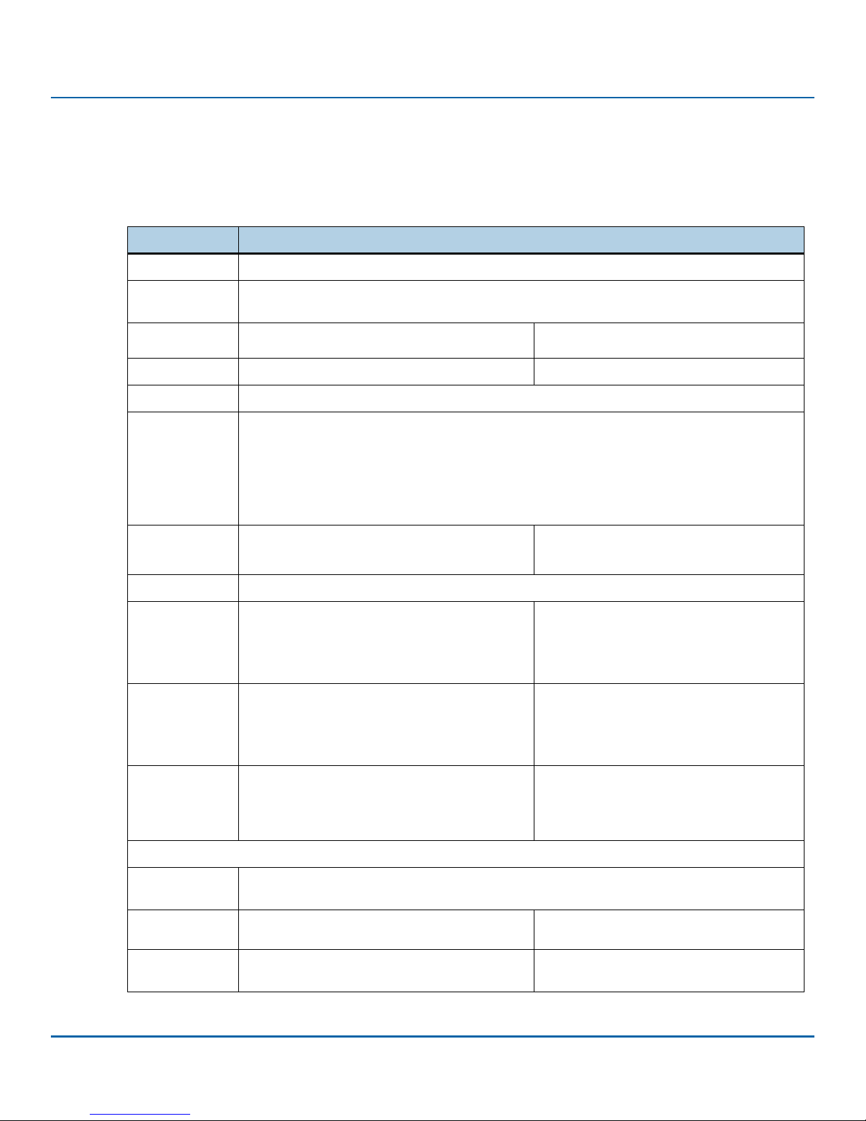
Table 1 Nytro XF1230 Card Features
Feature Description
Capacity
Certifications,
Eco-Compliance
Dimension
Endurance
Form
Interface
Compliance
Latency
NAND
240, 480, 960, 1920 GB
CE, UL, FCC, RCM, BSMI, KCC, Microsoft WHQL, SATA-IO
RoHS
(69.85±0.25) x (100±0.25) x (Max. 7) mm SSD Outer case can support suitable Z-height
for various host situations.
1> DWPD See Tab le 9 , Endurance, on page9.
2.5 Inch Standard SSD
Fully compliant with SATA revision 3.1, compatible with SATA 6.0Gb/s interface rates.
Fully compliant with ATA-8/ACS-4 Standard.
PIO, DMA, UDMA (up to 6, dependent on host) supported.
SATA 6.0Gb/s Native Command Queuing (NCQ): up to 32 commands.
SMART command transport (SCT) technology.
Data Set Management Command Trim support.
Read: 135 μs (Typ.)
Write: 55 μs (Typ.)
16 nm
Latency measured with transfer size 4 KB and
queue depth of 1 on a random workload, and
based on high density (1920 GB).
Performance
Random
(Sustained)
Performance
Sequential
(128 KB
Sustained)
Power
Consumption
Power Loss Protection
Power
Management
Power On Ready
Quality of
Service
4 KB Read: Up to 98K IOPS
4 KB Write: Up to 17K IOPS
8 KB Read: Up to 58K IOPS
8 KB Write: Up to 8K IOPS
Read: Up to 560MB/s
Write: Up to 490MB/s
Active: Up to 4.8 W
Idle: Up to 0.7 W
2.5 inch: 5 V SATA Supply
OS-aware hot plug/removal
Normal shut down: 5 s
Unsolicited shut down: 21 s
Read/Write: 0.2 ms / 1.4ms (99.9%)
Read/Write: 0.3 ms / 21ms (99.9999%)
Actual performance might vary depending on
use conditions and environment.
Typical I/O performance numbers measured
with a queue depth of 32, write cache enabled,
6Gb/s SAS chipset port, and the Intel RST driver.
Actual performance might vary depending on
use conditions and environment.
Typical I/O performance numbers as measured
with a queue depth of 32, write cache enabled,
6Gb/s SAS chipset port, and the Intel RST driver.
RMS Average.
NOTE This specification is for the 1920 GB drive;
smaller capacity drive have lower active
power.
Based on High Density (1920 GB).
Based on Random 4 KB, queue depth=1, and
1920 GB Density.
Seagate Nytro XF1230 SATA SSD Product Manual, Rev. B 5
Page 6
www.Seagate.com Introduction
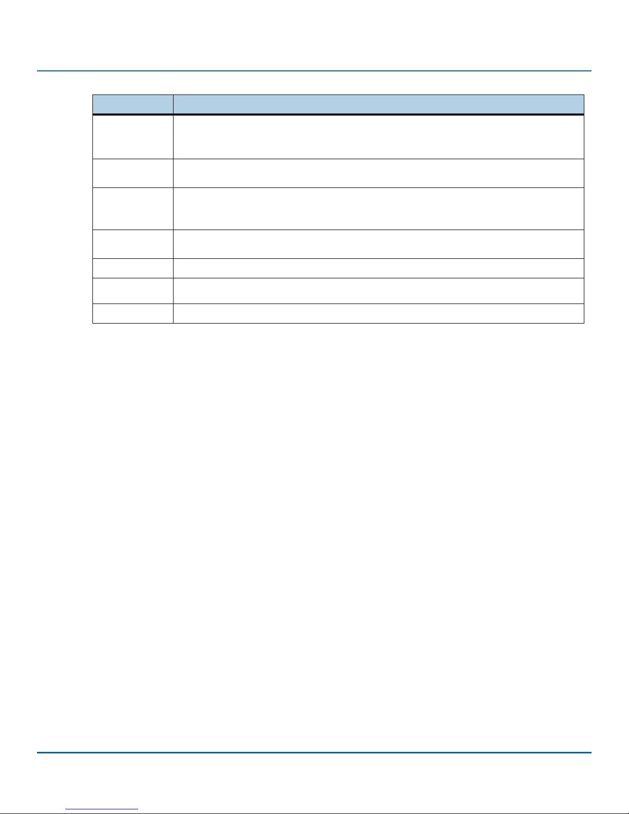
Table 1 Nytro XF1230 Card Features (continued)
Feature Description
MTBF: 2 million hours
Reliability
Shock
Temperature
Range
BER: 1 error in 10
End-to-End data-path protection
Operating: 1500G, duration 0.5ms
Non-Operating: 1500G, duration 0.5ms
0°C to 70°C
Temperature Sensor (SMART Attribute ID 194)
17
bits transferred (exponential)
(Operating)
Vibration
Voltage
Operating:20G, 10~2 KHz (Frequency)
Non-Operating: 20G, 10~2 KHz (Frequency)
5V±5%
Warran ty
Weight
Five years limited Warranty with Media Usage, based on the shorter of term or endurance usage of
the drive.
up to 85g ±5%
Seagate Nytro XF1230 SATA SSD Product Manual, Rev. B 6
Page 7
www.Seagate.com Specifications
2. Specifications
2.1 Models and Capacity
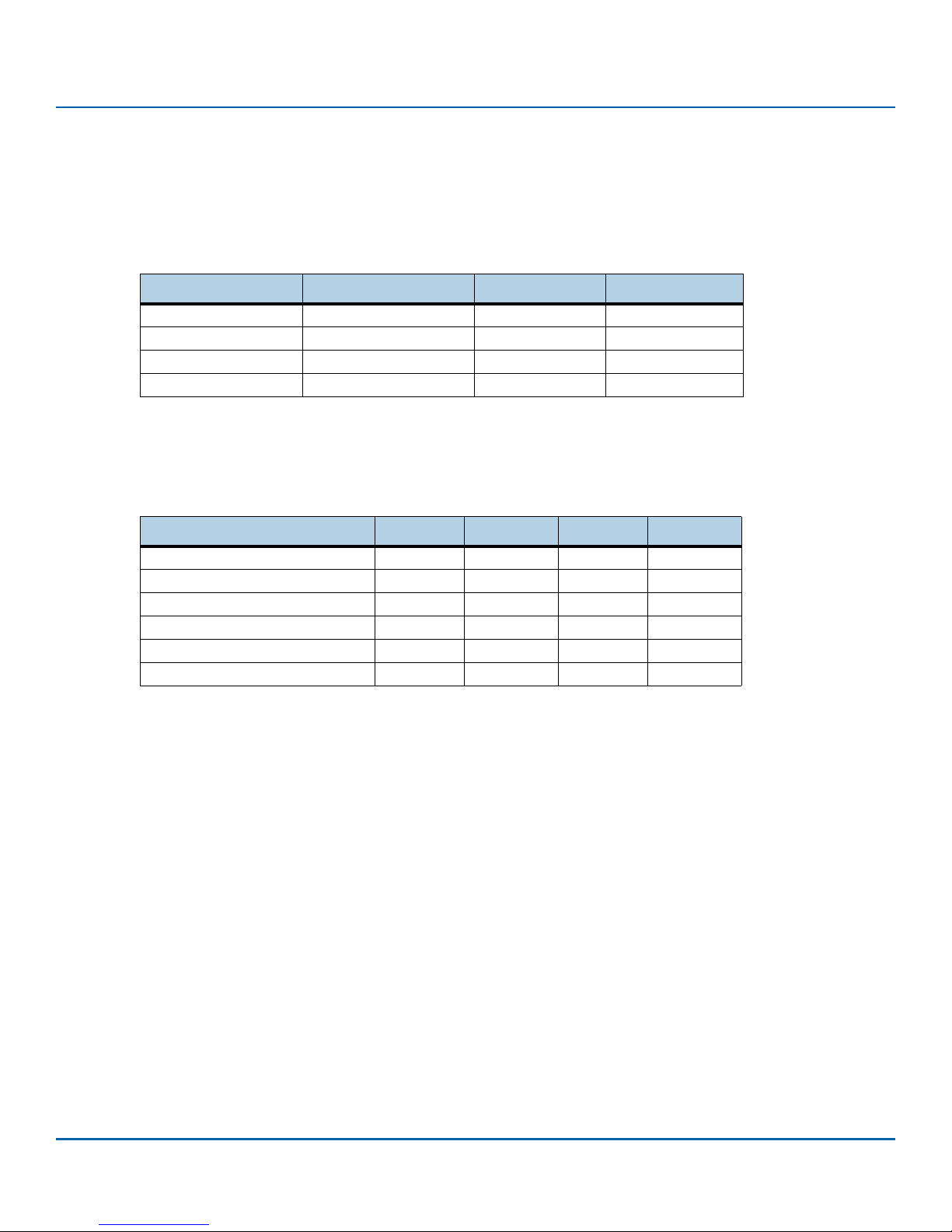
Table 2 Nytro XF1230 Card Models
Device Name Model Names Usable Capacity LBAs
Nytro XF1230 XF1230-1A0240 240 GB 468,862,128
Nytro XF1230 XF1230-1A0480 480 GB 937,703,088
Nytro XF1230 XF1230-1A0960 960 GB 1,875,385,008
Nytro XF1230 XF1230-1A1920 1920 GB 3,750,748,848
2.2 Performance
Table 3 Random Read/Write Input/Output Operations Per Second (IOPS)
Parameter 240 GB 480 GB 960 GB 1920 GB
Random 4 KB Read (IOPS) 98,000 98,000 98,000 98,000
Random 4 KB Write (IOPS) 8,000 15,000 16,000 17,000
Random 8 KB Read (IOPS) 58,000 58,000 58,000 58,000
Random 8 KB Write (IOPS) 4,000 7,500 8,000 7,500
Sequential Read (Sustained) 560MB/s 560MB/s 560MB/s 560MB/s
Sequential Write (Sustained) 290MB/s 500MB/s 460MB/s 430MB/s
NOTE Performance measured with queue depth set to 32.
4 KB = 4,096 bytes, 8 KB = 8,192 bytes.
Drive write cache enabled.
Measurements performed on Full Logical Block Address (LBA) range, sustained
for 2x Drive Capacity.
Set to 4 KB alignment.
Performance test precondition: Drive is preconditioned with 2x drive capacity
128 KB write IOs.
Measured on system with Intel Xeon E5-2640v3 and C610 chipset with
on-board AHCI controller running Microsoft Windows® 2012 R2 DC. System
variations, such as using the Intel RST driver, might affect measured results.
MB/s = 1,000,000 bytes/second.
Seagate Nytro XF1230 SATA SSD Product Manual, Rev. B 7
Page 8

www.Seagate.com Specifications
2.3 Power Consumption
The 2.5" drive receives DC power (+5 V) through the standard SATA 6.0Gb/s interface.
Table 4 Power Consumption
5 V Supply 240 GB 480 GB 960 GB 1920 GB
Operating Voltage range
Inrush Current
2.3.1 Operating Power Environmental Conditions
Table 5 Operating Power
Active Read – Average 2.0 W 2.1 W 2.2 W 2.4 W
Active Write – Average 2.9 W 3.9 W 4.7 W 4.8 w
Active Read – Burst 500 μS Average 2.2 W 2.2 W 2.3 W 2.4 w
Active Write – Burst 500 μS Average 3.1 W 4.7 W 7.4 W 7.4 W
Idle 0.6 W 0.6 W 0.7 W 0.7 W
5 V ± 5%
0.91 A
240 GB 480 GB 960 GB 1920 GB
5 V ± 5%
1.10 A
5 V ± 5%
1.20 A
5 V ±5%
1.60 A
Table 6 Temperature, Humidity, Shock
Specification Nytro XF1230
Temperature
Operating (case temperature at specific airflow)
Non-Operating
Humidity
Operating and Non-Operating
Shock
Operating and Non-Operating
0°C to 70°C
- 40°C to 95°C
5 to 95%
1500 G at 0.5 ms
NOTE Operating, as measured by temperature sensor, SMART Attribute ID 194.
Measured without condensation.
The Shock specification assumes that the SSD is mounted securely
with the input vibration applied to the drive mounting. Stimulus may
be applied in the X, Y or Z axis.
These specifications do not cover connection issues that may result
from testing at this level.
Operating Shock: The drive, as installed for normal operation,
operates error-free while subjected to intermittent shock not
exceeding specification. Shock may be applied in the X, Y, or Z-axis.
Shock must not be repeated more than once every 2 seconds.
Seagate Nytro XF1230 SATA SSD Product Manual, Rev. B 8
Page 9

www.Seagate.com Specifications
Non-Operating Shock: The limits of non-operating shock applies to all
conditions of handling and transportation. This includes isolated and
integrated drives. Shock may be applied in the X, Y, or Z-axis.
Tab le 7 Vib ration
Specification Nytro XF1230
Maximum Vibrations
Operating
Non-Operating
3.08 Grms (7-800 Hz)
16.3 Grms (20-2000 Hz)
NOTE The Vibration specification assumes that the SSD is mounted securely with the
input Vibration applied to the drive mounting screws. Stimulus may be applied
in the X, Y or Z axis. This specification does not cover connection issues that
may result from testing at this level
Operating Vibration: The drive, as installed for normal operation, shall
operate error free while subjected to specified vibration not
exceeding specification. Vibration may be applied in the X, Y, or Z-axis.
Non-Operating Vibration: The limits of non-operating vibration shall
apply to all conditions of handling and transportation. This includes
both isolated drive and integrated drives. Vibration may be applied in
the X, Y, or Z-axis.
2.4 Reliability
Table 8 Reliability
Mean time between failures (MTBF) 2 million hours
Bit Error Rate
2.5 Endurance
Tab le 9 Endu ran ce
Endurance Rating 0.5 DWPD 0.6 DWPD 0.6 7 DWPD 0.67 DWPD
NOTE SSD Endurance is lifetime on finite amount of writes. According to JEDEC
Specification Nytro XF1230
1 error in 10
Specification 240 GB 480 GB 960 GB 1920 GB
17
bits transferred (exponential)
JESD218 Calculation for SSD endurance rating.
DWPD is drive write per day.
Limited Warranty with Media Usage provides coverage for the warranty period
or the endurance usage of the drive.
Seagate Nytro XF1230 SATA SSD Product Manual, Rev. B 9
Page 10

www.Seagate.com Mechanical Information
3. Mechanical Information
3.1 Dimensions and Weight
Weight: 0.187 lbs, 85 g
Height: Maximum 7 mm
Width: 69.85±0.25
Length: 100±0.25
NOTE All dimensions are in millimeters.
Figure 1 Nytro XF1230 Dimensions
Seagate Nytro XF1230 SATA SSD Product Manual, Rev. B 10
Page 11

www.Seagate.com Pin and Signal Descriptions
4. Pin and Signal Descriptions
4.1 Serial ATA Interface Connector
Figure 2 Connector Physical Dimension and Connector Assembly
Seagate Nytro XF1230 SATA SSD Product Manual, Rev. B 11
Page 12

www.Seagate.com Pin and Signal Descriptions
4.2 Pin Locations
Figure 3 Layout of 2.5-inch Signal and Power Segment Pins
NOTE The 2.5-inch connector supports built in latching capability.
4.3 Connector Pin Signal Definitions
Table 10 Serial ATA Connector Pin Signal Definitions—2.5-inch Form Factors
Pin Name Definition
S1
S2
S3
S4
S5
S6
S7
Ground Ground
A+
A-
Ground Ground
B-
B+
Ground Ground
Key and spacing separate the signal and power segments.
Differential signal pair A and A-
Differential signal pair B and B-
Seagate Nytro XF1230 SATA SSD Product Manual, Rev. B 12
Page 13

www.Seagate.com Pin and Signal Descriptions
4.4 Power Pin Signal Definitions
Table 11 Serial ATA Power Pin Signal Definitions—2.5-inch Form Factors
Pin Function Definition
P1 V33 3.3 V Power; not used
P2 V33 3.3 V Power; not used
P3 V33 3.3 V Power; not used
P4 GND Ground
P5 GND Ground
P6 GND Ground
P7 V5 5 V Power
P8 V5 5 V Power
P9 V5 5 V Power
P10 GND Ground
P11 DAS Device Activity Signal
P12 GND Ground
P13 V12 12 V Power; not used
P14 V12 12 V Power; not used
P15 V12 12 V Power; not used
NOTE Key and spacing separate the signal and power segments.
Uses 5 V power only, 3.3 V (P1-P3) and 12 V (P13-P15) power are not
used.
Pins P1, P2, and P3; Pins P13, P14, and P15 are connected together.
They are not connected internally to the device, and the host may
apply voltage on these pins.
Ground pins are P4, P5, P6, P10, P12.
Signal pins and the rest of the 5V power pins are P8,P9.
Power pins P7, P8, and P9 are internally connected to one another
within the device
4.5 SSD Activity LED Indicator (Optional)
The Nytro XF1230 can support DAS Control function from the SSD module to indicate LED activity of host side.
The device includes a physical pin P11 for connecting device activity LEDs.
The signal provided to indicate activity of the device is a low-voltage and low-current driver intended for efficient
integration into current and future IC manufacturing processes. The signal is not suitable for directly driving an LED
and is first buffered using a circuit external to the device before driving an LED.
For DAS function operation, a Firmware function feature and R das are included as an option.
The DAS function firmware feature generates a Low/High toggle Activity signal input when the SSD is in a busy state
and generates a high Activity signal input when the SSD is in idle mode (Low level: GND, High level: 3.3V).
Using DAS function increases current because of the Activity LED operation.
Seagate Nytro XF1230 SATA SSD Product Manual, Rev. B 13
Page 14

www.Seagate.com Pin and Signal Descriptions
The DAS Firmware feature is disabled and the R das is opened when the DAS function is not in use.
Figure 4 Circuit of SSD Activity LED indication
Seagate Nytro XF1230 SATA SSD Product Manual, Rev. B 14
Page 15

www.Seagate.com Supported ATA Command List
5. Supported ATA Command List
The Nytro XF1230 complies with ATA-8/ACS-4. All mandatory and many optional commands and features are
supported.
5.1 ATA Feature Set
The following table shows the ATA feature set and commands that the Nytro XF1230 supports.
Table 12 ATA Feature Set
Featu re Supported
48-Bit Address feature set
General feature set
Native Command Queuing (NCQ) feature set
Power Management feature set
Security feature set
S.M.A.R.T feature set
5.2 ATA Command Description
The following table shows the ATA commands supported.
Table 13 ATA Command Description
Command
CHECK POWER MODE E5h SMART DISABLE OPERATION B0h/D9h
DATA SET MANAGEMENT 06h SMART ENABLE/DISABLE B0h/D2h
DOWNLOAD MICROCODE 92h SMART ENABLE OPERATION B0h/D8h
EXECUTE DEVICE DIAGNOSTIC 90h SMART EXECUTE OFFLINE B0h/D4h
FLUSH CACHE E7h SMART READ DATA B0h/D0h
FLUSH CACHE EXT EAh SMART READ LOG B0h/D5h
IDENTIFY DEVICE ECh SMART READ THRESHOLD B0h/D1h
IDLE E3h SMART RETURN STATUS B0h/DAh
IDLE IMMEDIATE E1h SMART SAVE ATB VALUES B0h/D3h
INITIALIZE DEVICE PARAMETERS 91h SMART WRITE LOG B0h/D6h
NOP 00h STANDBY E2h
READ BUFFER E4h STANDBY IMMEDIATE E0h
READ DMA C8h WRITE BUFFER E8h
READ DMA EXT 25h WRITE DMA CAh
READ DMA W/O RETRIES C9h WRITE DMA EXT 35h
READ FPDMA QUEUED 60h WRITE DMA FUA EXT 3Dh
READ LOG DMA EXT 47h WRITE DMA WITHOUT RETRIES CBh
READ LOG EXT 2Fh WRITE FPDMA QUEUED 61h
READ MULTIPLE C4h WRITE LOG DMA EXT 57h
READ MULTIPLE EXT 29h WRITE LOG EXT 3Fh
Code
(Hex)
Yes
Yes
Yes
Yes
Yes
Yes
Command
Code
(Hex)
Seagate Nytro XF1230 SATA SSD Product Manual, Rev. B 15
Page 16

www.Seagate.com Supported ATA Command List
Table 13 ATA Command Description (continued)
READ SECTOR(S) 20h WRITE MULTIPLE C5h
READ SECTOR(S) EXT 24h WRITE MULTIPLE EXT 39h
READ SECTOR(S) W/O RETRY 21h WRITE MULTIPLE FUA EXT CEh
READ VERIFY SECTOR(S) 40h WRITE SECTOR(S) 30h
READ VERIFY SECTOR(S) W/O RETRY 41h WRITE SECTOR(S) EXT 34h
READ VERIFY SECTOR(S) EXT 42h WRITE SECTORS WITHOUT RETRY 31h
RECALIBRATE 10h WRITE UNCORRECTABLE EXT 45h
REQUEST SENSE DATA EXT 0Bh
SECURITY DISABLE PASSWORD F6h
SECURITY ERASE PREPARE F3h
SECURITY ERASE UNIT F4h
SECURITY FREEZE LOCK F5h
SECURITY SET PASSWORD F1h
SECURITY UNLOCK F2h
SEEK 70h
SET FEATURES EFh
SET MULTIPLE MODE C6h
SLEEP E6h
5.2.1 Security
Command
Code
(Hex)
Command
Code
(Hex)
The user/master password is supported.
When the device receives a normal SECURITY ERASE UNIT command, the device erases all data blocks including
unallocated (hidden) blocks.
You can download firmware regardless of the security state.
5.2.1.1 Password Loss
If you lose the user password, you can access the device using the master password. If both passwords are lost, there is
no way to access the device. You can reset the device, and you can use it like a fresh drive but the old data is lost.
Seagate Nytro XF1230 SATA SSD Product Manual, Rev. B 16
Page 17

www.Seagate.com SMART Support
6. SMART Support
The Nytro XF1230 supports the S.M.A.R.T(Self-Monitoring, Analysis, and Reporting Technology) Command Set.
6.1 SMART Command Set
The Nytro XF1230 supports the SMART Command Set shown in the following table.
Table 14 SMART Attributes
Feature Field Values Command
D0h SMART READ DATA
D1h SMART READ ATTRIBUTE THRESHOLDS
D2h SMART ENABLE/DISABLE ATTRIBUTE AUTOSAVE
D3h SAVE ATTRIVUTE VALUES
D4h SMART EXECUTE OFF-LINE IMMEDIATE
00h* Execute SMART Off-Line routine
01h* Execute SMART Short Self-test routine (Off-Line)
02h* Execute SMART Extended Self-test routine (Off-Line)
03h* Execute SMART Conveyance self-test routine in off-line mode
04h* Execute SMART Selective self-test routine in off-line mode
7Fh* Abort Off-Line routine
81h* Execute SMART Short Self-test routine (Captive)
82h* Execute SMART Extended Self-test routine (Captive)
83h* Execute SMART Conveyance self-test routine in captive mode
84h* Execute SMART Selective self-test routine in captive mode
D5h SMART READ LOG
D6h SMART WRITE LOG
D8h SMART ENABLE OPERATIONS
D9h SMART DISABLE OPERATIONS
DAh
*Low LBA values
SMART RETURN STATUS
6.2 SMART Attributes
The Nytro XF1230 supports the SMART attributes shown in the following table.
Table 15 SMART Attributes
ID Attribute ID Description
1 Raw Read Error Rate Rate of hardware read errors that occurred when reading data from a device
5 Retired Block count Count of number of blocks that have been reallocated, excluding pending sectors
9 Power on hours The time accumulated while the power is on and operating
12 Drive Power cycle count Count of number of Power Cycles, excluding power mode commands
171 Program Fail Count Number of Error Events on Program
Seagate Nytro XF1230 SATA SSD Product Manual, Rev. B 17
Page 18

www.Seagate.com SMART Support
Table 15 SMART Attributes (continued)
ID Attribute ID Description
172 Erase Fail Count Number of Error Events on Erase
174 Unexpected Power Loss Count Number of Issue on Unexpected Power Loss
175 Maximum Program Fail Count Maximum number of Program Error Events per die
176 Maximum Erase Fail Count Maximum number of Erase Error Events per die
177 Endurance Used Indicates the number of NAND wear
178 Used Reserved Block Count Number of used reserved blocks
179 Used Reserved Block Count Number of used reserved blocks in SSD
180 End to End Error Detection Rate Number of error detections of the data path between host and NAND in SSD
during last power-on
181 Program Fail Count Number of Error Events on Program (Lifetime)
182 Erase Fail Count Number of Error Events on Erase (Lifetime)
183 SATA Downshift Count Number of times that SATA interface speed reduced
184 End to End Error Detection Count Number of error detection of the data path between host and NAND in SSD of
lifetime
187 Uncorrectable Error Count Uncorrectable Error Count
188 Command Timeout Count Number of total uncompleted commands
194 Temperature (Celsius) Temperature of the SSD
195 ECC Uncorrectable Error Rate Uncorrectable Error Count vs. Total read sector count
197 Current Pending Sector Count Number of unstable sectors which will be remapped on next write
201 Uncorrectable Soft Read Error Rate (UECC) Number of soft read errors (Count of UECC Error)
204 Soft ECC Correction Rate Count of errors corrected by software ECC [citation needed]
231 SSD Life Left (%) Indicates the approximate SSD life left, in terms of program/erase cycles or Flash
blocks currently available for use
234 Vendor Specific Information of Vendor
241 Total LBAs Written The total number of 512-byte sectors written during the entire lifetime of the
device.
242 Total LBAs Read The total number of 512-byte sectors read during the entire lifetime of the
device.
250 Read Error Retry Rate There is no reliable information available about this attribute.
6.3 SMART Trip
SMART trip (threshold exceeded condition) indicates impending degradation or fault condition. The host can issue a
SMART return status command (B0h/DAh) to communicate the reliability status of the drive. The threshold-exceeded
condition is also checked during drive self tests.
Seagate Nytro XF1230 SATA SSD Product Manual, Rev. B 18
Page 19

www.Seagate.com Safety, Standards, and Compliance
7. Safety, Standards, and Compliance
7.1 Safety Characteristics
All Seagate SSDs meet or exceed the requirements of UL flammability rating 94V-0. Each bare board is marked with
the supplier’s name or trademark, type, and UL flammability rating. A CB and UL report has been generated for
EN60950.
7.2 Electromagnetic Compliance and Standards
The Nytro XF1230 card is designed to minimize electromagnetic emissions, susceptibility to radio frequency energy,
and the effects of electrostatic discharge. The card carries the CE mark, RCM, Canadian Compliance Statement, KCC,
Taiwan BSMI, Japan VCCI, and FCC Class B, and the card is marked with the FCC Self-Certification logo. The card also
meets the requirements of CISPR Class B.
7.3 Standards
The Nytro XF1230 card is recognized in accordance with UL 60950-1 as tested by UL, CAN/CSA C22.2 No. 60950-1 and
IEC/EN60950-1 as tested by TUV SUD.
7.4 Electromagnetic Compatibility
Electromagnetic Compatibility Notices
Electromagnetic Compatibility Notices
This device complies with Part 15 of the FCC Rules. Operation is subject to the following two conditions:
This equipment has been tested and found to comply with the l imits for a Class B digital device, pursuant to part 15 of the FCC Rules. These limits are designed to provide
reasonable protection against harmful interference in a residential installation. This equipment generates, uses, and can radiate radio frequency energy and, if not
installed and used in accordance with the instructions, may cause harmful interference to radio communications. However, there is no guarantee that interference will
not occur in a particular installation. If this equipment does cause harmful interference to radio or television reception, which can be determined by turning the
equipment off and on, the user is encouraged to try to correct the interference by one or more of the following measures:
Shielded cables for SCSI connection external to the cabinet are used in the compliance testing of this Product. Seagate is not responsible for any radio or television
interference caused by unauthorized modification of this equipment or the substitution or attachment of connecting cables and equipment other than those specified
by Seagate Technology LLC. The correction of interferences caused by such unauthorized modification, substitution, or attachment will be the responsibility of the user.
The device is tested to comply with FCC standards for home or office use.
This Class B digital apparatus meets all requirements of the Canadian Interference-Causing Equipment Regulations.
Cet appareil numérique de la classe B respecte toutes les exigences du Règlement sur le matériel brouilleur du Canada.
• This device may not cause harmful interference, and
• This device must accept any interference received, including interference that may cause undesired operation.
• Reorient or relocate the receiving antenna.
• Increase the separation between the equipment and the receiver.
• Connect the equipment into an outlet on a circuit different from that to which the receiver is connected.
• Consult the dealer or an experienced radio/TV technician for help.
Seagate Nytro XF1230 SATA SSD Product Manual, Rev. B 19
Page 20

www.Seagate.com Safety, Standards, and Compliance
7.5 Electromagnetic Compliance
Seagate uses an independent laboratory to confirm compliance with the directives/standards for CE Marking and
C-Tick Marking. The Nytro XF1230 card was tested in a representative system for typical applications and complies
with the Electromagnetic Interference/Electromagnetic Susceptibility (EMI/EMS) for Class B products. The selected
system represents the most popular characteristics for test platforms. The system configurations include:
Typical current-use microprocessor
Keyboard
Monitor display
Printer
Mouse
Although the test system with this Seagate model complies with the directives and standards, we cannot guarantee
that all systems comply. The computer or server manufacturer or the system integrator must confirm EMC compliance
and provide the appropriate marking for their product.
7.6 Electromagnetic Compliance for the European Union
If this model has the CE Marking it complies with the European Union requirements of the Electromagnetic
Compatibility Directive 2004/108/EC as put into place on 20 July 2007.
7.7 Australian RCM
If this model has the RCM Marking it complies with the Australia/New Zealand Standard AS/NZ CISPR22 and meets the
Electromagnetic Compatibility (EMC) Framework requirements of Australia’s Spectrum Management Agency (SMA).
7.8 Korean KCC
If this model has the Korean Communications Commission (KCC) logo, it complies with KN22, KN 24, and KN61000.
7.9 Taiwanese BSMI
If this model has the Taiwanese certification mark then it complies with Chinese National Standard, CNS13438.
Seagate Nytro XF1230 SATA SSD Product Manual, Rev. B 20
Page 21

www.Seagate.com Safety, Standards, and Compliance
7.10 Japan VCCI
This is a Class B product based on the standard of the Voluntary Control Council for Interference from Information Technology Equipment (VCCI). If this is used near a
radio or television receiver in a domestic environment, it may cause radio interference. Install and use the equipment according to the instruction guide.
7.11 China Restriction of Hazardous Substances (RoHS)
Directive
This product has an Environmental Protection Use Period (EPUP) of 20 years. The following table
contains information mandated by China's "Marking Requirements for Control of Pollution Caused by
Electronic Information Products" Standard.
"O" indicates the hazardous and toxic substance content of the part (at the homogeneous material level) is lower than
the threshold defined by the China RoHS MCV Standard.
"X" indicates the hazardous and toxic substance content of the part (at the homogeneous material level) is over the
threshold defined by the China RoHS MCV Standard.
Seagate Nytro XF1230 SATA SSD Product Manual, Rev. B 21
Page 22

www.Seagate.com Safety, Standards, and Compliance
7.11.1 Reference Documents
In case of conflict between this document and any reference document, this document takes precedence.
Table 16 Reference Documents
Name
Apr. 2007 SATA-IO Commands for ATA-8
Feb. 2011 Solid-State Drive (SSD) Requirements and Endurance Test Method(JESD218A)
Jul. 2011 Serial ATA Revision 3.1
Jul. 2011 IDEMA (LBA1-03_standard.doc)
Jul. 2012 SOLID-STATE DRIVE (SSD) Endurance Workload(JESD219A)
Jul. 2015 ATA/ATAPI Command Set -4 (ACS-4) Working Draft
Nov. 2011 ISO/IEC 14776-xxxSCSI Block Commands-3 (SBC-3) Standard (T10/1799-D)
Seagate Nytro XF1230 SATA SSD Product Manual, Rev. B 22
Page 23

Seagate Technology LLC
AMERICAS Seagate Technology LLC 10200 South De Anza Boulevard, Cupertino, California 95014, United States, 408-658-1000
ASIA/PACIFIC Seagate Singapore International Headquarters Pte. Ltd. 7000 Ang Mo Kio Avenue 5, Singapore 569877, 65-6485-3888
EUROPE, MIDDLE EAST AND AFRICA Seagate Technology SAS 16-18 rue du Dôme, 92100 Boulogne-Billancourt, France, 33 1-4186 10 00
Publication Number: 100797573, Rev. B
April 2016
 Loading...