

Page 1
100834145, Rev B
November 2018
Seagate® Nytro® 1351, 1551 SSD
Nytro 1351 - Read Intensive Models Nytro 1551 - Mixed Workload Models
SED - TCG Enterprise
SED - TCG Enterprise
XA240LE10023
XA240ME10023
XA480LE10083 XA480ME10083
XA960LE10083
XA960ME10083
XA1920LE10083
XA1920ME10083
XA3840LE10083 XA3840ME10083
SED - TCG Opal
SED - TCG Opal
XA240LE10043 XA240ME10043
XA480LE10103
XA480ME10103
XA960LE10103
XA960ME10103
XA1920LE10103 XA1920ME10103
XA3840LE10103
XA3840ME10103
Standard
Standard
XA240LE10003
XA240ME10003
XA480LE10063
XA480ME10063
XA960LE10063 XA960ME10063
XA1920LE10063
XA1920ME10063
XA3840LE10063
XA3840ME10063
Product Manual
Page 2
Revision History
Version and Date Description of Changes
Rev B, November Updated:
Table 4 Performance - Capacity Optimized (7% OP - Default as Shipped).
Table 5 Performance - Performance Optimized (28% OP - Available with Tunable Capacity).
Section 2.7, Endurance.
Thermal non-operating note in Table 7 Temperature, Humidity, Shock.
Non-technical updates.
Rev A, July 2018 First release of the document.
© 2018, Seagate Technology LLC All rights reserved. Publication number: 100834145, Rev B, November 2018
Seagate Technology reserves the right to make changes to the product(s) or information disclosed herein at any time without notice.
Seagate, Seagate Technology and the Spiral logo are registered trademarks of Seagate Technology LLC in the United States and/or other countries. IronWolf and DuraWrite are either trademarks or registered trademarks
of Seagate Technology LLC or one of its affiliated companies in the United States and/or other countries. All other trademarks or registered trademarks are the property of their respective owners.
No part of this publication may be reproduced in any form without written permission of Seagate Technology LLC. Call 877-PUB-TEK1(877-782-8351) to request permission.
When referring to drive capacity, one gigabyte, or GB, equals one billion bytes and one terabyte, or TB, equals one trillion bytes. Your computer’s operating system may use a different standard of measurement and report
a lower capacity. In addition, some of the listed capacity is used for formatti ng and other funct ions, and thus will not be available for data storage. Actual quantities will vary based on various factors, including file size, file
format, features and application software. Actual data rates may vary depending on operating environment and other factors. The export or re-export of hardware or software containing encryption may be regulated by
the U.S. Department of Commerce, Bureau of Industry and Security (for more information, visit www.bis.doc.gov), and controlled for import and use outside of the U.S. Seagate reserves the right to change, without notice,
product offerings or specifications.
Page 3

Contents
Seagate Technology Support Services . . . . . . . . . . . . . . . . . . . . . . . . . . . . . . . . . . . . . . . . . . . . . . . . . . . . . . . . . . . . . . . . . . . . . . . . . . . . . . 5
1. Introduction . . . . . . . . . . . . . . . . . . . . . . . . . . . . . . . . . . . . . . . . . . . . . . . . . . . . . . . . . . . . . . . . . . . . . . . . . . . . . . . . . . . . . . . . . . . . . . . . . . . . 6
2. Specifications . . . . . . . . . . . . . . . . . . . . . . . . . . . . . . . . . . . . . . . . . . . . . . . . . . . . . . . . . . . . . . . . . . . . . . . . . . . . . . . . . . . . . . . . . . . . . . . . . . . 9
2.1 Models and Capacity . . . . . . . . . . . . . . . . . . . . . . . . . . . . . . . . . . . . . . . . . . . . . . . . . . . . . . . . . . . . . . . . . . . . . . . . . . . . . . . . . . . . . . . . . . . . . . . . . . . . . . . . . . . . . . . . 9
2.2 Performance . . . . . . . . . . . . . . . . . . . . . . . . . . . . . . . . . . . . . . . . . . . . . . . . . . . . . . . . . . . . . . . . . . . . . . . . . . . . . . . . . . . . . . . . . . . . . . . . . . . . . . . . . . . . . . . . . . . . . . 10
2.3 Power . . . . . . . . . . . . . . . . . . . . . . . . . . . . . . . . . . . . . . . . . . . . . . . . . . . . . . . . . . . . . . . . . . . . . . . . . . . . . . . . . . . . . . . . . . . . . . . . . . . . . . . . . . . . . . . . . . . . . . . . . . . . . 12
2.4 Environmental Conditions . . . . . . . . . . . . . . . . . . . . . . . . . . . . . . . . . . . . . . . . . . . . . . . . . . . . . . . . . . . . . . . . . . . . . . . . . . . . . . . . . . . . . . . . . . . . . . . . . . . . . . . . . 13
2.5 Reliability . . . . . . . . . . . . . . . . . . . . . . . . . . . . . . . . . . . . . . . . . . . . . . . . . . . . . . . . . . . . . . . . . . . . . . . . . . . . . . . . . . . . . . . . . . . . . . . . . . . . . . . . . . . . . . . . . . . . . . . . . 14
2.6 Tunable Capacity . . . . . . . . . . . . . . . . . . . . . . . . . . . . . . . . . . . . . . . . . . . . . . . . . . . . . . . . . . . . . . . . . . . . . . . . . . . . . . . . . . . . . . . . . . . . . . . . . . . . . . . . . . . . . . . . . . 14
2.7 Endurance . . . . . . . . . . . . . . . . . . . . . . . . . . . . . . . . . . . . . . . . . . . . . . . . . . . . . . . . . . . . . . . . . . . . . . . . . . . . . . . . . . . . . . . . . . . . . . . . . . . . . . . . . . . . . . . . . . . . . . . . . 15
2.7.1 Expected DWPD . . . . . . . . . . . . . . . . . . . . . . . . . . . . . . . . . . . . . . . . . . . . . . . . . . . . . . . . . . . . . . . . . . . . . . . . . . . . . . . . . . . . . . . . . . . . . . . . . . . . . . . . . . . . 15
2.7.1.1 Nytro 1351 Workload WA to DWPD Reference - 7% OP . . . . . . . . . . . . . . . . . . . . . . . . . . . . . . . . . . . . . . . . . . . . . . . . . . . . . . . . . . . . . . . . . 16
2.7.1.2 Nytro 1351 Workload WA to DWPD Reference - 28% OP . . . . . . . . . . . . . . . . . . . . . . . . . . . . . . . . . . . . . . . . . . . . . . . . . . . . . . . . . . . . . . . . 16
2.7.1.3 Nytro 1551 Workload WA to DWPD Reference - 7% OP . . . . . . . . . . . . . . . . . . . . . . . . . . . . . . . . . . . . . . . . . . . . . . . . . . . . . . . . . . . . . . . . . 17
2.7.1.4 Nytro 1551 Workload WA to DWPD Reference - 28% OP . . . . . . . . . . . . . . . . . . . . . . . . . . . . . . . . . . . . . . . . . . . . . . . . . . . . . . . . . . . . . . . . 17
2.7.2 Endurance Warranty . . . . . . . . . . . . . . . . . . . . . . . . . . . . . . . . . . . . . . . . . . . . . . . . . . . . . . . . . . . . . . . . . . . . . . . . . . . . . . . . . . . . . . . . . . . . . . . . . . . . . . . . 18
3. Mechanical Information . . . . . . . . . . . . . . . . . . . . . . . . . . . . . . . . . . . . . . . . . . . . . . . . . . . . . . . . . . . . . . . . . . . . . . . . . . . . . . . . . . . . . . . . 19
3.1 Dimensions and Weight . . . . . . . . . . . . . . . . . . . . . . . . . . . . . . . . . . . . . . . . . . . . . . . . . . . . . . . . . . . . . . . . . . . . . . . . . . . . . . . . . . . . . . . . . . . . . . . . . . . . . . . . . . . 19
4. Pin and Signal Descriptions . . . . . . . . . . . . . . . . . . . . . . . . . . . . . . . . . . . . . . . . . . . . . . . . . . . . . . . . . . . . . . . . . . . . . . . . . . . . . . . . . . . . . 20
4.1 Serial ATA Interface Connector . . . . . . . . . . . . . . . . . . . . . . . . . . . . . . . . . . . . . . . . . . . . . . . . . . . . . . . . . . . . . . . . . . . . . . . . . . . . . . . . . . . . . . . . . . . . . . . . . . . . . 20
4.2 Pin Locations . . . . . . . . . . . . . . . . . . . . . . . . . . . . . . . . . . . . . . . . . . . . . . . . . . . . . . . . . . . . . . . . . . . . . . . . . . . . . . . . . . . . . . . . . . . . . . . . . . . . . . . . . . . . . . . . . . . . . . 21
4.3 Connector Pin Signal Definitions . . . . . . . . . . . . . . . . . . . . . . . . . . . . . . . . . . . . . . . . . . . . . . . . . . . . . . . . . . . . . . . . . . . . . . . . . . . . . . . . . . . . . . . . . . . . . . . . . . . 21
4.4 Power Pin Signal Definitions . . . . . . . . . . . . . . . . . . . . . . . . . . . . . . . . . . . . . . . . . . . . . . . . . . . . . . . . . . . . . . . . . . . . . . . . . . . . . . . . . . . . . . . . . . . . . . . . . . . . . . . 22
4.5 SSD Activity LED Indicator (Optional) . . . . . . . . . . . . . . . . . . . . . . . . . . . . . . . . . . . . . . . . . . . . . . . . . . . . . . . . . . . . . . . . . . . . . . . . . . . . . . . . . . . . . . . . . . . . . . . 22
5. Supported ATA Command List . . . . . . . . . . . . . . . . . . . . . . . . . . . . . . . . . . . . . . . . . . . . . . . . . . . . . . . . . . . . . . . . . . . . . . . . . . . . . . . . . . 24
5.1 ATA Feature Set . . . . . . . . . . . . . . . . . . . . . . . . . . . . . . . . . . . . . . . . . . . . . . . . . . . . . . . . . . . . . . . . . . . . . . . . . . . . . . . . . . . . . . . . . . . . . . . . . . . . . . . . . . . . . . . . . . . 24
5.2 ATA Command Description . . . . . . . . . . . . . . . . . . . . . . . . . . . . . . . . . . . . . . . . . . . . . . . . . . . . . . . . . . . . . . . . . . . . . . . . . . . . . . . . . . . . . . . . . . . . . . . . . . . . . . . . 25
5.3 Security . . . . . . . . . . . . . . . . . . . . . . . . . . . . . . . . . . . . . . . . . . . . . . . . . . . . . . . . . . . . . . . . . . . . . . . . . . . . . . . . . . . . . . . . . . . . . . . . . . . . . . . . . . . . . . . . . . . . . . . . . . . 26
5.3.1 Password Loss . . . . . . . . . . . . . . . . . . . . . . . . . . . . . . . . . . . . . . . . . . . . . . . . . . . . . . . . . . . . . . . . . . . . . . . . . . . . . . . . . . . . . . . . . . . . . . . . . . . . . . . . . . . . . . 26
6. SMART Support . . . . . . . . . . . . . . . . . . . . . . . . . . . . . . . . . . . . . . . . . . . . . . . . . . . . . . . . . . . . . . . . . . . . . . . . . . . . . . . . . . . . . . . . . . . . . . . . 27
6.1 SMART Command Set . . . . . . . . . . . . . . . . . . . . . . . . . . . . . . . . . . . . . . . . . . . . . . . . . . . . . . . . . . . . . . . . . . . . . . . . . . . . . . . . . . . . . . . . . . . . . . . . . . . . . . . . . . . . . . 27
6.2 SMART Attributes . . . . . . . . . . . . . . . . . . . . . . . . . . . . . . . . . . . . . . . . . . . . . . . . . . . . . . . . . . . . . . . . . . . . . . . . . . . . . . . . . . . . . . . . . . . . . . . . . . . . . . . . . . . . . . . . . . 28
6.3 SMART Trip . . . . . . . . . . . . . . . . . . . . . . . . . . . . . . . . . . . . . . . . . . . . . . . . . . . . . . . . . . . . . . . . . . . . . . . . . . . . . . . . . . . . . . . . . . . . . . . . . . . . . . . . . . . . . . . . . . . . . . . . 29
7. Standards and Reference Documents . . . . . . . . . . . . . . . . . . . . . . . . . . . . . . . . . . . . . . . . . . . . . . . . . . . . . . . . . . . . . . . . . . . . . . . . . . . . 30
7.1 Regulatory Model Numbers . . . . . . . . . . . . . . . . . . . . . . . . . . . . . . . . . . . . . . . . . . . . . . . . . . . . . . . . . . . . . . . . . . . . . . . . . . . . . . . . . . . . . . . . . . . . . . . . . . . . . . . . 30
7.2 Agency and Safety Certifications . . . . . . . . . . . . . . . . . . . . . . . . . . . . . . . . . . . . . . . . . . . . . . . . . . . . . . . . . . . . . . . . . . . . . . . . . . . . . . . . . . . . . . . . . . . . . . . . . . . 30
7.2.1 Safety Certification . . . . . . . . . . . . . . . . . . . . . . . . . . . . . . . . . . . . . . . . . . . . . . . . . . . . . . . . . . . . . . . . . . . . . . . . . . . . . . . . . . . . . . . . . . . . . . . . . . . . . . . . . . 30
7.2.2 Electromagnetic Compatibility . . . . . . . . . . . . . . . . . . . . . . . . . . . . . . . . . . . . . . . . . . . . . . . . . . . . . . . . . . . . . . . . . . . . . . . . . . . . . . . . . . . . . . . . . . . . . . 30
7.2.3 Electromagnetic Susceptibility . . . . . . . . . . . . . . . . . . . . . . . . . . . . . . . . . . . . . . . . . . . . . . . . . . . . . . . . . . . . . . . . . . . . . . . . . . . . . . . . . . . . . . . . . . . . . . . 30
7.2.4 Electromagnetic Compliance . . . . . . . . . . . . . . . . . . . . . . . . . . . . . . . . . . . . . . . . . . . . . . . . . . . . . . . . . . . . . . . . . . . . . . . . . . . . . . . . . . . . . . . . . . . . . . . . 30
7.2.5 European Union (EU) CE Marking Requirements . . . . . . . . . . . . . . . . . . . . . . . . . . . . . . . . . . . . . . . . . . . . . . . . . . . . . . . . . . . . . . . . . . . . . . . . . . . . . . 31
7.2.6 Australian and New Zealand RCM Compliance Mark . . . . . . . . . . . . . . . . . . . . . . . . . . . . . . . . . . . . . . . . . . . . . . . . . . . . . . . . . . . . . . . . . . . . . . . . . . 31
7.2.7 Canada ICES-003 . . . . . . . . . . . . . . . . . . . . . . . . . . . . . . . . . . . . . . . . . . . . . . . . . . . . . . . . . . . . . . . . . . . . . . . . . . . . . . . . . . . . . . . . . . . . . . . . . . . . . . . . . . . . 31
7.2.8 South Korean Certification Mark . . . . . . . . . . . . . . . . . . . . . . . . . . . . . . . . . . . . . . . . . . . . . . . . . . . . . . . . . . . . . . . . . . . . . . . . . . . . . . . . . . . . . . . . . . . . . 31
7.2.9 Morocco Commodity Mark . . . . . . . . . . . . . . . . . . . . . . . . . . . . . . . . . . . . . . . . . . . . . . . . . . . . . . . . . . . . . . . . . . . . . . . . . . . . . . . . . . . . . . . . . . . . . . . . . . 31
7.2.10 Taiwanese BSMI . . . . . . . . . . . . . . . . . . . . . . . . . . . . . . . . . . . . . . . . . . . . . . . . . . . . . . . . . . . . . . . . . . . . . . . . . . . . . . . . . . . . . . . . . . . . . . . . . . . . . . . . . . . . 32
Seagate® Nytro® 1351, 1551 SSD Product Manual, Rev. B 3
Page 4

Contents
7.3 Environmental Protection . . . . . . . . . . . . . . . . . . . . . . . . . . . . . . . . . . . . . . . . . . . . . . . . . . . . . . . . . . . . . . . . . . . . . . . . . . . . . . . . . . . . . . . . . . . . . . . . . . . . . . . . . . 32
7.3.1 European Union Restriction of Hazardous Substance Law . . . . . . . . . . . . . . . . . . . . . . . . . . . . . . . . . . . . . . . . . . . . . . . . . . . . . . . . . . . . . . . . . . . . 32
7.3.2 China Requirements —China RoHS 2 . . . . . . . . . . . . . . . . . . . . . . . . . . . . . . . . . . . . . . . . . . . . . . . . . . . . . . . . . . . . . . . . . . . . . . . . . . . . . . . . . . . . . . . . 33
7.3.3 Taiwan Requirements — Taiwan RoHS . . . . . . . . . . . . . . . . . . . . . . . . . . . . . . . . . . . . . . . . . . . . . . . . . . . . . . . . . . . . . . . . . . . . . . . . . . . . . . . . . . . . . . . 34
Seagate® Nytro® 1351, 1551 SSD Product Manual, Rev. B 4
Page 5

Seagate Technology Support Services
For Product Support, visit: http://www.seagate.com/support/
For information regarding online support and services, visit: http://www.seagate.com/contacts/
Available services include:
Presales & Technical support
Global Support Services telephone numbers & business hours
Authorized Service Centers
Recovery Services
For information regarding Warranty Support, visit: http://www.seagate.com/support/warranty-and-replacements/
Seagate® Nytro® 1351, 1551 SSD Product Manual, Rev. A 5
Page 6
www.Seagate.com
1. Introduction
The Seagate® Nytro® 1351 and Nytro 1551 are next generation enterprise SATA SSDs that deliver enterprise class
features in a 2.5-inch × 7 mm form factor.
Table 1 Features
Feature Description
Capacity
Certifications,
Eco-Compliance
Dimension
Endurance
Logical Block Size
240, 480, 960, 1920, or 3840 GB
CE, UL, cUL, RCM, BSMI, KCC, TUV, Microsoft WHCK, Microsoft WHQL, SATA-IO
RoHS, WEEE
Width: 69.85±0.25 millimeters
Length: 100±0.25 millimeters
Height: Maximum 7 millimeters
Lifetime Endurance: Nytro 1551 3 DWPD Class; Nytro 1351 1 DWPD Class
512 bytes
Form Factor
Interface
Compliance
NAND
Flash Controller
Performance
2.5 inch × 7 mm Standard SSD
Fully compliant with SATA revision 3.2 and 3.3, compatible with SATA 6.0Gb/s and 3.0Gb/s interface
rates.
Fully compliant with ATA/ATAPI Command Set – 4 and supports all mandatory ATA commands
defined in the ATA8-ACS specification.
— ATA General Feature Command Set
— Power Management Command Set
— Security Mode Feature Set
— SMART Command Set
— Device Statistics
— SMART Command Transport
— Dataset Management Command Set
— Host Protected Area Command Set
— 48-bit Address Command Set
— General Purpose Log Command Set
— Native Command Queuing
— Software Settings Prevention
— ATA Sanitize Command Set
— Identify Device Command Set
— Log Addresses Requirement
PIO, DMA, UDMA (up to 6, dependent on host) supported.
SATA 6.0Gb/s Native Command Queuing (NCQ): up to 32 commands.
SMART command transport (SCT) technology.
Data Set Management Command Trim support.
TLC
Seagate proprietary Flash Controller
Seagate DuraWriteTM Technology for improved performance
See Section 2.1, Models and Capacity, on page 9.
Power
See Section 2.3, Power, on page 12.
Consumption
Seagate® Nytro® 1351, 1551 SSD Product Manual, Rev. B
6
Page 7
www.Seagate.com
Table 1 Features (Continued)
Feature Description
Power Loss Data
In-process writes to the NAND are completed in the event of an unexpected power loss
Protection
Power
OS-aware hot-plug/hot-swap support
Management
Power On Ready
See Section 2.3, Power, on page 12.
Power-loss data protection
SMART thermal monitoring
MTBF: 2 million hours @ 55°C
UBER: 1 read error per 10
End-to-End data-path protection
Seagate SHIELD – Advanced ECC for improved reliability with minimal impact on performance
17
bits read
— Adaptive Code Rates
— Intelligent Noise handling
Reliability
— Adaptive Read Voltage calibration
— Multi-Level Error Correction - Best-in-class LDPC implementation
Seagate RAISE (Redundant Array of Independent Silicon Elements)
— Protects user data from various flash silicon failures
— RAID-like data protection and recovery from flash memory failures
— Operates within a single drive without impacting performance
— Corrects a single page, single block or single die failure within one RAISE stripe on capacities
480GB and higher. For 240GB, corrects a single page, single block or single plane failure within
one RAISE stripe.
Seagate Secure™
Secure Supply Chain
— O-TTPS (Open Trusted Technology Provider Standard) compliant
SD&D (Secure Download & Diagnostics)
Security
— Cryptographic FW signing, RSA 2048 key
— Secure Boot
— Locked Diagnostic Port
— FW Authenticity and Integrity Verification, SHA 256
Instant Secure EraseTCG Enterprise Protocol, AES-256 Encryption models
TCG Opal Protocol, AES-256 Encryption models
Shock
Vibration
Volta ge
Data Retention
Operating: 1000G, duration 0.5ms
Non-Operating: 1000G, duration 0.5ms
Operating: Random, 3.8 Grms, 10-3000Hz, Uniform PSD:0.005 G^2/Hz
Non-Operating: Random, 7 Grms, 10-500Hz, Uniform PSD:0.01 G^2/Hz
5 V (240GB, 480GB)
5 V and 12 V (960GB, 1920GB, 3840GB)
3 months power-off retention at 40°C once the drive reaches the rated write endurance (EOL)
Temperature
Range
Thermal gradient
Operating: 0°C to 70°C
Non-operating: -40°C to 85°C
Operating: 20°C/hour
Non-operating: 30°C/hour
Seagate® Nytro® 1351, 1551 SSD Product Manual, Rev. B
7
Page 8

www.Seagate.com
Table 1 Features (Continued)
Feature Description
Tunabl e Ca pacit y
Set to Capacity Optimized or Performance Optimized
Warranty
Weight
Five years limited Warranty with Media Usage, based on the shorter of term or endurance usage of
the drive. See Section 2.7, Endurance, on page 15.
up to 77g ±5%
Seagate® Nytro® 1351, 1551 SSD Product Manual, Rev. B
8
Page 9
www.Seagate.com Models and Capacity
2. Specifications
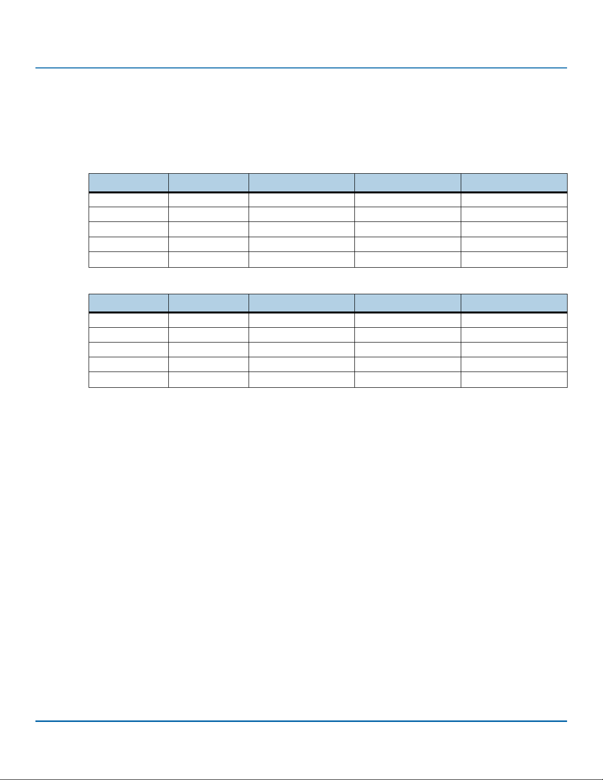
2.1 Models and Capacity
Table 2 Nytro 1351 - Read Intensive - 1 DWPD Models
Capacity (GB) LBA Count SED - TCG Enterprise SED - TCG Opal Standard
240 468,862,128 XA240LE10023 XA240LE10043 XA240LE10003
480 937,703,088 XA480LE10083 XA480LE10103 XA480LE10063
960 1,875,385,008 XA960LE10083 XA960LE10103 XA960LE10063
1920 3,750,748,848 XA1920LE10083 XA1920LE10103 XA1920LE10063
3840 7,501,476,528 XA3840LE10083 XA3840LE10103 XA3840LE10063
Table 3 Nytro1551 - Mixed Workload - 3 DWPD Models
Capacity (GB) LBA Count SED - TCG Enterprise SED - TCG Opal Standard
240 468,862,128 XA240ME10023 XA240ME10043 XA240ME10003
480 937,703,088 XA480ME10083 XA480ME10103 XA480ME10063
960 1,875,385,008 XA960ME10083 XA960ME10103 XA960ME10063
1920 3,750,748,848 XA1920ME10083 XA1920ME10103 XA1920ME10063
3840 7,501,476,528 XA3840ME10083 XA3840ME10103 XA3840ME10063
Seagate® Nytro® 1351, 1551 SSD Product Manual, Rev. B
9
Page 10
www.Seagate.com Performance
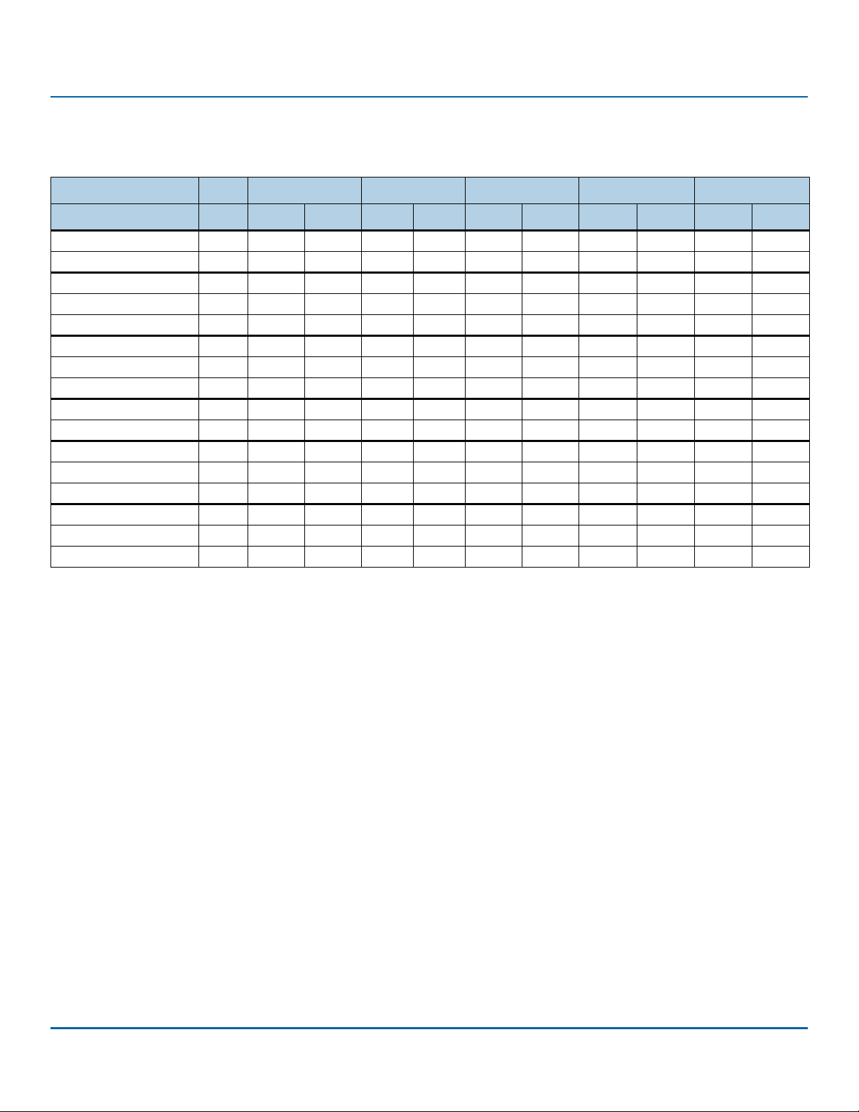
2.2 Performance
Table 4 Performance - Capacity Optimized (7% OP - Default as Shipped)
Capacity Units 240 GB 480 GB 960 GB 1920 GB 3840 GB
Compressibility % 0% 20% 0% 20% 0% 20% 0% 20% 0% 20%
128K SR QD32 MB/s 564 564 564 564 564 564 564 564 564 564
128K SW QD32 MB/s 226 325 460 533 535 536 535 536 535 536
4K RR QD32 KIOPs52547780919293948789
4K R70R QD32 KIOPs17322845395545614661
4K RW QD32 KIOPs 8 29 15 51 22 59 23 49 22 41
8K RR QD32 KIOPs38465457575757575657
8K R70R QD32 KIOPs11241532233930413043
8K RW QD32 KIOPs4 16832133914321227
4K RR Latency QD1 usec 156 154 154 150 153 150 159 159 178 172
4K RW Latency QD1 usec 118 37 66 38 60 39 59 38 59 37
4K RR QD32 99% CI usec 1800 1800 800 800 600 600 600 600 700 700
4K R70R QD32 99% CI usec 7300 4700 5000 3700 3900 3000 3700 2800 3400 2600
4K RW QD32 99% CI usec 6700 3000 3800 1700 3000 800 2900 1900 3000 2000
4K RR QD32 99.99% CI usec 2000 2000 1800 1500 800 1000 800 900 1800 1800
4K R70R QD32 99.99% CI usec 14000 8800 9500 7500 7800 6300 7000 5500 6000 5600
4K RW QD32 99.99% CI usec 8800 5700 5800 3000 4400 2100 3900 2000 3900 2300
NOTE Information on performance:
0% refers to data that cannot be compressed and 20% refers to data for
which the size can be losslessly compressed by 20%. Performance values
shown is based on data compressibility values of 0% and 20% as set with
VDBench.
The scripts that were used to arrive at these measurements are available
on request.
MB is 10^6 bytes. MB/s = 10^6 bytes/sec.
4 KB = 4,096 bytes, 8 KB = 8,192 bytes.
All workloads set to 4 KB alignment.
All metrics represent sustained values, across full LBA range.
Drive write cache is active and protected by Power Loss Data Protection
(PLDP) feature.
Performance test precondition: The drive is preconditioned with 2x drive
capacity 128 KB sequential write IOs, prior to sequential testing, followed
by 6 hours per 1 TB drive capacity of 4K random write IOs, at queue depth
32, prior to random testing.
Results obtained with a direct SATA port connection to host and may vary
with capacity, endurance and system configuration. The HBA used could
also affect measured results.
Seagate® Nytro® 1351, 1551 SSD Product Manual, Rev. B
10
Page 11
www.Seagate.com Performance
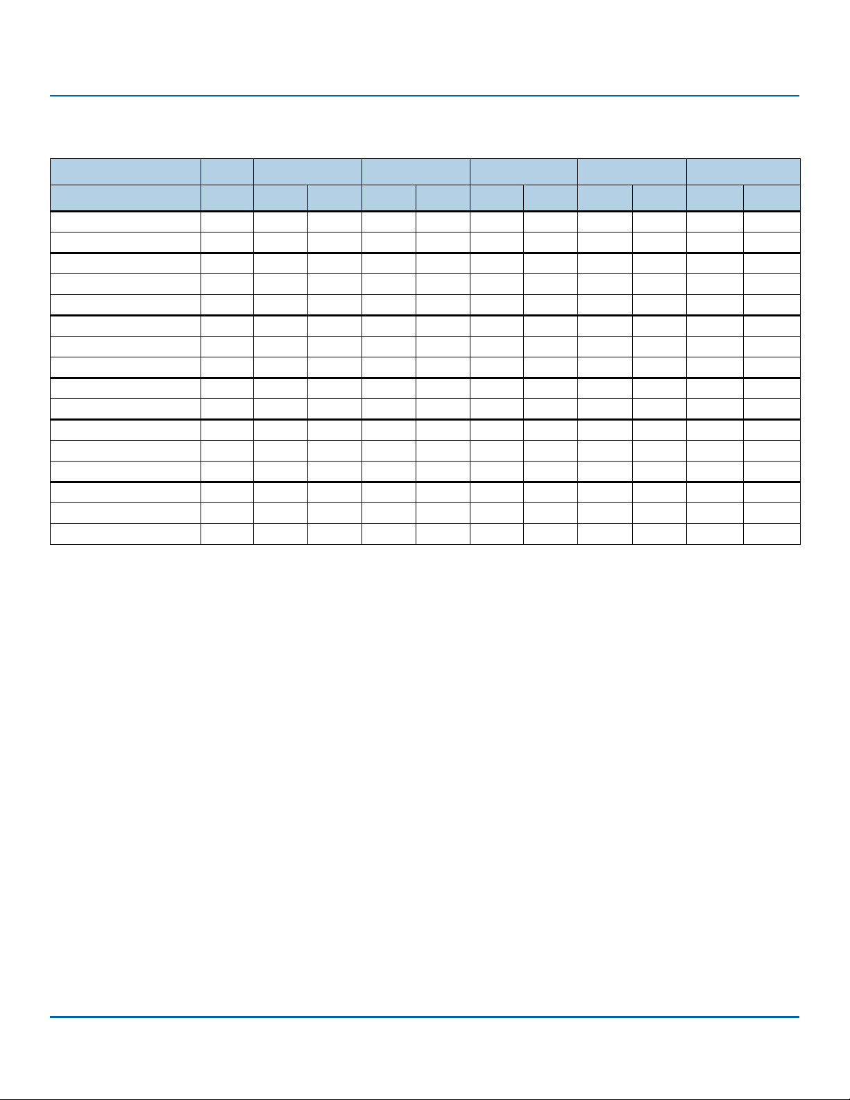
Table 5 Performance - Performance Optimized (28% OP - Available with Tunable Capacity)
Capacity Units 200 GB 400 GB 800 GB 1600 GB 3200 GB
Compressibility % 0% 20% 0% 20% 0% 20% 0% 20% 0% 20%
128K SR QD32 MB/s 564 564 564 564 564 564 564 564 564 564
128K SW QD32 MB/s 230 330 470 536 536 536 536 536 536 536
4K RR QD32 KIOPs5557818492939494 89 92
4K R70R QD32 KIOPs2735394949595769 60 71
4K RW QD32 KIOPs1838336748704868 45 67
8K RR QD32 KIOPs4450575757575757 55 57
8K R70R QD32 KIOPs1927283635424047 41 48
8K RW QD32 KIOPs1022194233463345 29 43
4K RR Latency QD1 usec 150 145 150 146 142 140 144 140 156 150
4K RW Latency QD1 usec5537423443354338 46 39
4K RR QD32 99% CI usec 1700 1500 700 700 600 600 500 500 700 600
4K R70R QD32 99% CI usec 5300 4200 4000 3400 3500 2900 3100 2500 2800 2000
4K RW QD32 99% CI usec 4000 2900 3000 1500 1500 700 1100 700 1400 800
4K RR QD32 99.99% CI usec 2000 2000 1300 1000 900 900 800 800 1300 1000
4K R70R QD32 99.99% CI usec 9800 8600 8000 7100 6600 5600 6000 5000 5400 5000
4K RW QD32 99.99% CI usec 6300 5000 6000 3900 3400 3300 2800 1800 2500 2700
NOTE Information on performance:
0% refers to data that cannot be compressed and 20% refers to data for
which the size can be losslessly compressed by 20%. Performance values
shown is based on data compressibility values of 0% and 20% as set with
VDBench.
The scripts that were used to arrive at these measurements are available
on request.
MB is 10^6 bytes. MB/s = 10^6 bytes/sec.
4 KB = 4,096 bytes, 8 KB = 8,192 bytes.
All workloads set to 4 KB alignment.
All metrics represent sustained values, across full LBA range.
Drive write cache is active and protected by Power Loss Data Protection
(PLDP) feature.
Performance test precondition: The drive is preconditioned with 2x drive
capacity 128 KB sequential write IOs, prior to sequential testing, followed
by 6 hours per 1 TB drive capacity of 4K random write IOs, at queue depth
32, prior to random testing.
Results obtained with a direct SATA port connection to host and may vary
with capacity, endurance and system configuration. The HBA used could
also affect measured results.
Seagate® Nytro® 1351, 1551 SSD Product Manual, Rev. B
11
Page 12

www.Seagate.com Power
2.3 Power
The drive uses either 5 V or it uses 5 and 12 V DC power.
Table 6 Power
240 GB 480 GB 960 GB 1920 GB 3840 GB
Power
Voltage (V) 5 5 5 / 12 5 / 12 5 / 12
Power Consumption
Overall average active power (W) 2.3 2.7 3.2 3.4 3.5
Maximum average active power (W) 2.6 3.2 4.5 5.1 5.0
Peak (25uS sample) burst active power (W)
5V limited to 6W
Idle (W) 1.1 1.1 1.2 1.2 1.2
NOTE 5V power limited to 6 W beyond which power will be drawn from 12 V.
4.9 5.4 7.8 8.8 8.6
Seagate® Nytro® 1351, 1551 SSD Product Manual, Rev. B
12
Page 13

www.Seagate.com Environmental Conditions
2.4 Environmental Conditions
Table 7 Temperature, Humidity, Shock
Specification Value s
Te mp er at ur e
Operating: 0°C to 70°C
Non-operating: -40°C to 85°C
Humidity Operating and Non-Operating: 5% - 95%
Shock Operating: 1000G, duration 0.5ms
Non-Operating: 1000G, duration 0.5ms
Thermal gradient
Operating: 20°C/hour
Non-operating: 30°C/hour
NOTE Operating, as measured by temperature sensor, SMART Attribute ID 194.
Measured without condensation.
The non-operating environmental range beyond the operating
environmental range is limited to 180 days in original packaging or 60
days otherwise.
The Shock specification assumes that the SSD is mounted securely with
the input vibration applied to the drive mounting. Stimulus may be
applied in the X, Y or Z axis.
Operating Shock: The drive, as installed for normal operation, operates
error-free while subjected to intermittent shock not exceeding
specification. Shock may be applied in the X, Y, or Z-axis. Shock must not
be repeated more than once every 2 seconds.
Non-Operating Shock: The limits of non-operating shock applies to all
conditions of handling and transportation. This includes isolated and
integrated drives. Shock may be applied in the X, Y, or Z-axis.
Tab le 8 Vib ration
Specification Valu es
Maximum Vibrations Operating: Random, 3.8 Grms, 10-3000Hz, Uniform PSD:0.005 G^2/Hz
Non-Operating: Random, 7 Grms, 10-500Hz, Uniform PSD:0.01 G^2/Hz
NOTE The Vibration specification assumes that the SSD is mounted securely with the
input Vibration applied to the drive mounting screws. Stimulus may be applied
in the X, Y or Z axis.
Operating Vibration: The drive, as installed for normal operation, shall
operate error free while subjected to specified vibration not exceeding
specification. Vibration may be applied in the X, Y, or Z-axis.
Non-Operating Vibration: The limits of non-operating vibration shall apply
to all conditions of handling and transportation. This includes both
isolated drive and integrated drives. Vibration may be applied in the X, Y,
or Z-axis.
Seagate® Nytro® 1351, 1551 SSD Product Manual, Rev. B
13
Page 14

www.Seagate.com Reliability
2.5 Reliability
Table 9 Reliability
Specification Value s
Mean time between failures (MTBF)
Uncorrectable Bit Error Rate
NOTE The SSD achieves the specified MTBF in an operational environment that
complies with the operational temperature range specified in this manual.
Operating temperatures are measured by the temperature sensor, SMART
Attribute ID,
on page 28.
2.6 Tunable Capacity
You can set the SSD to Capacity Optimized or Performance Optimized states. When shipped, the SSD is in the Capacity
Optimized state. Use the Seagate utility, SeaTools
state at deployment, prior to installing a file system. Changing states does not change the rated TBW specification for
endurance.
2 million hours @ 55°C
<1 error in 10
Primary Temperature, provided in Table 20, “SMART Attributes,”
TM
SSD to set the states. Seagate recommends to set the required
17
bits read
Seagate® Nytro® 1351, 1551 SSD Product Manual, Rev. B
14
Page 15

www.Seagate.com Endurance
2.7 Endurance
2.7.1 Expected DWPD
DuraWrite can enhance endurance depending on the characteristics of the write workload. Realized Host DWPD can
be gaged from the table below based on the actual Write Amplification (WA) measurements. To capture the WA value:
1. Read the Lifetime Writes from Host.
2. Read the Lifetime Writes to Flash.
3. Run the application workload of interest for several hours.
4. Read the two SMART attributes again to find both the host writes and flash writes accumulated over the time the
workload was running.
5. The WA value is accumulated flash writes divided by host writes.
6. Use this WA value to find an approximate Host DWPD value in the following table.
7. Related workload characteristics are given in the table as a reference.
Seagate® Nytro® 1351, 1551 SSD Product Manual, Rev. B
15
Page 16

www.Seagate.com Endurance
2.7.1.1 Nytro 1351 Workload WA to DWPD Reference - 7% OP
Table 10 Workload WA to DWPD Reference - 7% OP
User Capacity 240 480 960 1920 3840
Measured WA
Host
DWPD
Host TBW
Reference Workload
0.8 2.2 960 1920 3840 7680 15400 Highly sequential and compressible
1 1.8 768 1540 3070 6140 12300 Highly sequential and somewhat compressible
1.1 1.6 698 1400 2790 5590 11200 Fully sequential and not compressible
1.75 1 439 878 1760 3510 7020 Moderately compressible and predominantly random
2 0.9 384 768 1540 3070 6140 Moderately compressible and highly random
3 0.6 256 512 1020 2050 4100 Slightly compressible and completely random
4 0.4 192 384 768 1540 3070 Highly incompressible and random
2.7.1.2 Nytro 1351 Workload WA to DWPD Reference - 28% OP
Table 11 Workload WA to DWPD Reference - 28% OP
User Capacity 200 400 800 1600 3200
Measured WA
Host
DWPD
Host TBW
0.8 2.6 960 1920 3840 7680 15400 Highly sequential and compressible
1 2.1 768 1540 3070 6140 12300 Highly sequential and somewhat compressible
1.1 1.9 698 1400 2790 5590 11200 Fully sequential and not compressible
1.35 1.6 569 1140 2280 4550 9100 Moderately compressible and highly random
2 1.1 384 768 1540 3070 6140 Slightly compressible and completely random
3 0.7 256 512 1020 2050 4100 Highly incompressible and random
Reference Workload
NOTE Information on endurance:
DWPD is drive write per day.
DWPD values based on as shipped, 7%, or 28% capacity points.
Lifetime Writes to Flash are available from the corresponding SMART
attribute, See, Tab le 2 0, SMART Attributes, on page 28.
Lifetime Writes from Host are available from the corresponding SMART
attribute, see
Write Amplification (WA) is calculated as the cumulative writes to flash
divided by the cumulative writes from the host SMART attribute values
over the same time interval.
Seagate® Nytro® 1351, 1551 SSD Product Manual, Rev. B
Table 20, SMART Attributes, on page 28.
16
Page 17

www.Seagate.com Endurance
2.7.1.3 Nytro 1551 Workload WA to DWPD Reference - 7% OP
Table 12 Workload WA to DWPD Reference - 7% OP
User Capacity 240 480 960 1920 3840
Measured WA Host DWPD Host TBW
0.8 5.1 2240 4480 8960 17900 35800 Highly sequential and compressible
1 4.1 1790 3580 7170 14300 28700 Highly sequential and somewhat compressible
1.1 3.7 1630 3260 6520 13000 26100 Fully sequential and not compressible
1.35 3 1330 2650 5310 10600 21200 Moderately compressible and predominantly random
2 2 896 1790 3580 7170 14300 Moderately compressible and highly random
3 1.4 597 1190 2390 4780 9560 Slightly compressible and completely random
4 1 448 896 1790 3580 7170 Highly incompressible and random
2.7.1.4 Nytro 1551 Workload WA to DWPD Reference - 28% OP
Table 13 Workload WA to DWPD Reference - 28% OP
User Capacity 200 400 800 1600 3200
Measured WA Host DWPD Host TBW
0.8 6.1 2240 4480 8960 17900 35800 Highly sequential and compressible
1 4.9 1790 3580 7170 14300 28700 Highly sequential and somewhat compressible
1.1 4.5 1630 3260 6520 13000 26100 Fully sequential and not compressible
1.35 3.6 1330 2650 5310 10600 21200 Moderately compressible and highly random
2 2.5 896 1790 3580 7170 14300 Slightly compressible and completely random
3 1.6 597 1190 2390 4780 9560 Highly incompressible and random
Reference Workload
Reference Workload
NOTE Information on endurance:
DWPD is drive write per day.
DWPD values based on as shipped, 7%, or 28% capacity points.
Lifetime Writes to Flash are available from the corresponding SMART
attribute, See, Tab le 2 0, SMART Attributes, on page 28.
Lifetime Writes from Host are available from the corresponding SMART
attribute, see
Write Amplification (WA) is calculated as the cumulative writes to flash
divided by the cumulative writes from the host SMART attribute values
over the same time interval.
Seagate® Nytro® 1351, 1551 SSD Product Manual, Rev. B
Table 20, SMART Attributes, on page 28.
17
Page 18

www.Seagate.com Endurance
2.7.2 Endurance Warranty
The endurance warranty is based on total writes to the flash media.
Table 14 Total Bytes Written to Flash
As Shipped
Capacity
240 GB 480 GB 960 GB 1920 GB 3840 GB
Nytro 1351 768 TB 1540 TB 3070 TB 6140 TB 12300 TB
Nytro 1551 1790 TB 3580 TB 7170 TB 14300 TB 28700 TB
NOTE Information on endurance:
TB=10^12 bytes
Limited Warranty with Media Usage provides coverage for the warranty
period or the endurance usage of the drive, which ever comes first.
SSD endurance is based on lifetime writes to the flash media.
Lifetime Writes to Flash are available from the corresponding SMART
attribute, See, Table 20, “SMART Attributes,” on page 28.
Seagate® Nytro® 1351, 1551 SSD Product Manual, Rev. B
18
Page 19

www.Seagate.com Dimensions and Weight
3. Mechanical Information
3.1 Dimensions and Weight
Weight: 77 g
Height: Maximum 7 mm
Width: 69.85±0.25
Length: 100±0.25
NOTE All dimensions are in millimeters.
Figure 1 Dimensions
Seagate® Nytro® 1351, 1551 SSD Product Manual, Rev. B
19
Page 20

www.Seagate.com Serial ATA Interface Connector
4. Pin and Signal Descriptions
4.1 Serial ATA Interface Connector
Figure 2 Connector Physical Dimension and Connector Assembly
Seagate® Nytro® 1351, 1551 SSD Product Manual, Rev. B
20
Page 21

www.Seagate.com Pin Locations
4.2 Pin Locations
Figure 3 Layout of 2.5-inch Signal and Power Segment Pins
NOTE The 2.5-inch connector supports built in latching capability.
4.3 Connector Pin Signal Definitions
Table 15 Serial ATA Connector Pin Signal Definitions—2.5-inch Form Factors
Pin Name Definition
S1
S2
S3
S4
S5
S6
S7
NOTE Key and spacing separate the signal and power segments.
Ground Ground
A+
A-
Ground Ground
B-
B+
Ground Ground
Differential signal pair +A and A-
Differential signal pair +B and B-
Seagate® Nytro® 1351, 1551 SSD Product Manual, Rev. B
21
Page 22

www.Seagate.com Power Pin Signal Definitions
4.4 Power Pin Signal Definitions
Table 16 Serial ATA Power Pin Signal Definitions—2.5-inch Form Factors
Pin Function Definition
P1 V33 3.3 V Power; not used
P2 V33 3.3 V Power; not used
P3 V33 DevSlp; do not connect 3.3 V
P4 GND Ground
P5 GND Ground
P6 GND Ground
P7 V5 5 V Power
P8 V5 5 V Power
P9 V5 5 V Power
P10 GND Ground
P11 DAS Device Activity Signal
P12 GND Ground
P13 V12 12 V Power
P14 V12 12 V Power
P15 V12 12 V Power
NOTE Key and spacing separate the signal and power segments.
Uses 12 V and 5 V power only. The 240 GB and 480 GB models use 5 V
supply only.
Ground pins are P4, P5, P6, P10, and P12.
P7, P8, and P9 are 5V power pins and are connected internally on the
drive.
P13, P14, and P15 are 12V power pins and are connected internally on the
drive.
4.5 SSD Activity LED Indicator (Optional)
The SSD can support DAS Control function from the SSD module to indicate LED activity of host side.
The device includes a physical pin P11 for connecting device activity LEDs.
The signal provided to indicate activity of the device is a low-voltage and low-current driver. The signal from the
device is not suitable for directly driving an LED and is first buffered using a circuit external to the device before
driving an LED.
The DAS function firmware feature generates a Low and High toggle Activity signal on pin 11 when the SSD is in a
busy state and generates a high Activity signal input when the SSD is in idle mode (Low level: GND, High level: 2.85 V).
The DAS Firmware feature is disabled and the R das is opened when the DAS function is not in use.
of SSD Activity LED indication, on page 23.
See Figure 4, Circuit
Seagate® Nytro® 1351, 1551 SSD Product Manual, Rev. B
22
Page 23

www.Seagate.com SSD Activity LED Indicator (Optional)
Figure 4 Circuit of SSD Activity LED indication
Seagate® Nytro® 1351, 1551 SSD Product Manual, Rev. B
23
Page 24

www.Seagate.com ATA Feature Set
5. Supported ATA Command List
The SSD complies with ATA-8/ACS-4. All mandatory and many optional commands and features are supported.
5.1 ATA Feature Set
The following table shows the ATA feature set and commands that the SSD supports.
Table 17 ATA Feature Set
Featu re
Power Management Command Set
Security Mode Feature Set
SMART Command Set
Device Statistics
SMART Command Transport
Dataset Management Command Set
Host Protected Area Command Set
48-bit Address Command Set
General Purpose Log Command Set
Native Command Queuing
Software Settings Prevention
ATA Sanitize Command Set
Identify Device Command Set
Seagate® Nytro® 1351, 1551 SSD Product Manual, Rev. B
24
Page 25

www.Seagate.com ATA Command Description
5.2 ATA Command Description
The following table shows the ATA commands supported.
Table 18 ATA Command Description
Command
NOP 00h
DATA SET MANAGEMENT 06h DOWNLOAD MICROCODE 92h
REQUEST SENSE DATA EXT 0Bh DOWNLOAD MICROCODE DMA 93h
READ SECTORS 20h SMART B0h
READ SECTORS EXT 24h SANITIZE DEVICE B4h
READ DMA EXT 25h READ MULTIPLE C4h
READ MULTIPLE EXT 29h WRITE MULTIPLE C5h
READ LOG EXT 2Fh SET MULTIPLE MODE C6h
WRITE SECTORS 30h READ DMA C8h
WRITE SECTORS EXT 34h WRITE DMA CAh
WRITE DMA EXT 35h WRITE MULTIPLE FUA EXT CEh
WRITE MULTIPLE EXT 39h STANDBY IMMEDIATE E0h
WRITE DMA FUA EXT 3Dh IDLE IMMEDIATE E1h
WRITE LOG EXT 3Fh STANDBY E2h
READ VERIFY SECTORS 40h IDLE E3h
READ VERIFY SECTORS EXT 42h READ BUFFER E4h
ZERO EXT 44h CHECK POWER MODE E5h
WRITE UNCORRECTABLE EXT 45h SLEEP E6h
READ LOG DMA EXT 47h FLUSH CACHE E7h
WRITE LOG DMA EXT 57h WRITE BUFFER E8h
TRUSTED NON-DATA 5Bh READ BUFFER DMA E9h
TRUSTED RECEIVE 5Ch FLUSH CACHE EXT EAh
TRUSTED RECEIVE DMA 5Dh WRITE BUFFER DMA EBh
TRUSTED SEND 5Eh IDENTIFY DEVICE ECh
TRUSTED SEND DMA 5Fh SET FEATURES EFh
READ FPDMA QUEUED 60h SECURITY SET PASSWORD F1h
WRITE FPDMA QUEUED 61h SECURITY UNLOCK F2h
NCQ QUEUE MANAGEMENT 63h SECURITY ERASE PREPARE F3h
SEND FPDMA QUEUED 64h SECURITY ERASE UNIT F4h
RECEIVE FPDMA QUEUED 65h SECURITY FREEZE LOCK F5h
SET DATE & TIME EXT 77h SECURITY DISABLE PASSWORD F6h
ACCESSIBLE MAX ADDRESS CONFIG 78h
Code
(Hex)
Command
EXECUTE DEVICE DIAGNOSTICS 90h
Code
(Hex)
Seagate® Nytro® 1351, 1551 SSD Product Manual, Rev. B
25
Page 26

www.Seagate.com Security
5.3 Security
The user/master password is supported.
When the device receives a normal SECURITY ERASE UNIT command, the device erases all data blocks including
unallocated (hidden) blocks.
You can download firmware regardless of the security state.
Other security features:
TCG- Enterprise and TCG-Opal support
Crypto-erase sanitization
Block-level sanitization
Secure update of firmware
5.3.1 Password Loss
If you lose the user password, you can access the device using the master password. If both passwords are lost, there is
no way to access the device. For TCG Opal SSDs, where the credentials are no longer known, PSID Revert can be used
to regain the use of the SSD but all of the data on the drive will be erased.
Seagate® Nytro® 1351, 1551 SSD Product Manual, Rev. B
26
Page 27

www.Seagate.com SMART Command Set
6. SMART Support
6.1 SMART Command Set
The SSD supports the SMART Command Set shown in the following table.
Table 19 SMART Commands
Feature Field Values Command
D0h SMART READ DATA
D1h SMART READ ATTRIBUTE THRESHOLDS
D2h SMART ENABLE/DISABLE ATTRIBUTE AUTOSAVE
D3h SAVE ATTRIBUTE VALUES
D4h SMART EXECUTE OFF-LINE IMMEDIATE
00h* Execute SMART Off-Line routine
01h* Execute SMART Short Self-test routine (Off-Line)
02h* Execute SMART Extended Self-test routine (Off-Line)
03h* Execute SMART Conveyance self-test routine in off-line mode
04h* Execute SMART Selective self-test routine in off-line mode
7Fh* Abort Off-Line routine
81h* Execute SMART Short Self-test routine (Captive)
82h* Execute SMART Extended Self-test routine (Captive)
83h* Execute SMART Conveyance self-test routine in captive mode
84h* Execute SMART Selective self-test routine in captive mode
D5h SMART READ LOG
D6h SMART WRITE LOG
D8h SMART ENABLE OPERATIONS
D9h SMART DISABLE OPERATIONS
DAh
*Low LBA values
SMART RETURN STATUS
Seagate® Nytro® 1351, 1551 SSD Product Manual, Rev. B
27
Page 28

www.Seagate.com SMART Attributes
6.2 SMART Attributes
The SSD supports the SMART attributes shown in the following table.
Table 20 SMART Attributes
Name
Raw Read Error Rate
Reallocated Sector Count
Power-On-Hours
Power Cycle Count
Flash GB Erased
Lifetime PS4 Entry Count
Lifetime PS3 Entry Count
Grown Bad Block Count
Program Fail Count 171 Count of the number of Flash Program failures. Counter
Erase Fail Count 172 Count of the number of Flash Erase failures. Counter
Average Program/Erase Count
Unexpected Power Loss Count
Wear Range Delta
SATA/PCIe Interface Downshift Count
Uncorrectable ECC Count
Primary Temperature
RAISE ECC Correctable Count
Uncorrectable Read Error Count
SATA R-Error (CRC) Error Count
Drive Life Protection Status
Default
Assignment
1
5
9
12
100
102
103
170
173
174
177
183
187
194
195
198
199
230
Description Units
A normalized rate of moderate to severe latency
causing correctable errors.
Count of the number of blocks that have been
reallocated, excluding pending sectors.
Count of the lifetime power on hours in the Active
or Idle ATA state.
Count of the number of complete power up cycles.
Excludes power mode state changes with power
continuously applied.
Count in GB of the lifetime erases of flash for all
purposes.
Count of the number of times the PS4 power state
is entered.
Count of the number of times the PS3 power state
is entered.
Count of the number of retired flash blocks post
manufacturing.
Count of the average number of program/erase
cycles on all good blocks.
Count of the number of complete power loss
events not preceded by a shutdown command.
Excludes power mode state changes with power
continuously applied.
Difference between the most and least worn blocks
with regards to the maximum rated P-E cycles
(most-least)/max*100.
Count of the number of times SATA interface rate
reduction is negotiated.
Count of the number of unsuccessful ECC recovery
attempts where higher level recovery methods also
failed.
Current, lifetime maximum and lifetime minimum
temperature.
Count of the number of times RAISE successfully
recovered data.
Count of the number of times an uncorrectable
error is returned to the host on a read command.
Count of the number of detected SATA R-Errors
experienced on the SATA receiver.
Power fail protection available. 100d, 64h unprotected
Percentage
Counter
Hours
Counter
Count in Giga bytes
(2^30)
Counter
Counter
Counter
Counter
Counter
Percentage
Counter
Counter
Celsius (Signed data)
Counter
Counter
Counter
SSD RO, 90d, 5Ah
protected
Seagate® Nytro® 1351, 1551 SSD Product Manual, Rev. B
28
Page 29

www.Seagate.com SMART Trip
Table 20 SMART Attributes
Name
SSD Life Left
Available Reserved Space
Lifetime Writes to Flash
Lifetime Writes from Host
Lifetime Reads from Host
Free Space
6.3 SMART Trip
SMART trip (threshold exceeded condition) indicates impending degradation or fault condition. The host can issue a
SMART return status command (B0h/DAh) to communicate the reliability status of the drive. The threshold-exceeded
condition is also checked during drive self tests.
Default
Assignment
231
232
233
241
242
243
Description Units
Approximate percent SSD life left, in terms of
program/erase cycles or Flash blocks currently
available for use.
Ratio of currently available internal reserved space
to as built reserved space.
Sum in GB of the lifetime writes to flash for all
purposes.
Sum in GB of the lifetime writes for all host write
commands.
Sum in GB of the lifetime reads for all host read
commands.
Available user capacity in MB and percent of
currently set user capacity.
Percentage
Percentage
Sum in Giga bytes
(2^30)
Sum in Giga bytes
(2^30)
Sum in Giga bytes
(2^30)
Percentage User MB
Free and percentage
user space remaining
Seagate® Nytro® 1351, 1551 SSD Product Manual, Rev. B
29
Page 30

www.Seagate.com Regulatory Model Numbers
7. Standards and Reference Documents
Each Hard Drive and Solid State Drive ("device") has a product label that includes certifications that are applicable to
that specific drive. The following information provides an overview of requirements that may be applicable to the
drive.
7.1 Regulatory Model Numbers
The following regulatory model number represents all features and configurations within the series:
STA010
7.2 Agency and Safety Certifications
7.2.1 Safety Certification
These products are certified to meet the requirements of UL/cUL 60950-1, EN 60950-1, and may also include, IEC
62368, UL 62368 and EN 62368.
7.2.2 Electromagnetic Compatibility
The device, as delivered, is designed for system integration and installation into a suitable enclosure prior to use. The
drive is supplied as a subassembly and is not subject to Subpart B of Part 15 of the FCC Rules.
The design characteristics of the drive serve to minimize radiation when installed in an enclosure that provides
reasonable shielding. The device is capable of meeting the Class B limits of the FCC Rules and Regulations of the
Canadian Department of Communications when properly packaged; however, it is the user’s responsibility to assure
that the device meets the appropriate EMI requirements in their system.
7.2.3 Electromagnetic Susceptibility
The device as delivered is tested to meet susceptibility requirements in a representative enclosure. It is the
responsibility of those integrating the drive within their systems to perform those tests required and design their
system to ensure that equipment operating in the same system as the drive or external to the system does not
adversely affect the performance of the device.
7.2.4 Electromagnetic Compliance
Seagate uses an independent laboratory to confirm compliance with the EMC directives and standards. The device
was tested in a representative system for typical applications.Although the test system with this Seagate model
complies with the directives/standards, we cannot guarantee that all systems will comply. The computer
manufacturer or system integrator shall confirm EMC compliance and provide the appropriate marking for their
product.
Seagate® Nytro® 1351, 1551 SSD Product Manual, Rev. B
30
Page 31

www.Seagate.com Agency and Safety Certifications
ࣗط یࡈ߇ΰח
%
ɼࢽࡈ؏ܞݦࢢ
ࢇ Е ɼࢽࡈ% ࢷળࢶଢԻ۰ ࣯Ի
ɼࢽ߾۰ یࡈଜЕ ʨࡶ ּࢶࡳԻ ଜֲ ֻҘ
ࠇ߾۰یࡈଟܹݡТЬ
7.2.5 European Union (EU) CE Marking Requirements
Devices that display the CE mark comply with the European Union (EU) requirements specified in the Electromagnetic
Compatibility Directive (2014/30/EU). Testing is performed to the levels specified by the product standards for
Information Technology Equipment (ITE). Emission levels are defined by EN 55032:2012, Class B and the immunity
levels are defined by EN 55024.
The devices also meet the requirements of The Low Voltage Directive (LVD) 2014/35/EU.
Although CE-marked Seagate devices comply with all relevant regulatory requirements and standards for the drives,
Seagate cannot guarantee that all system-level products into which the devices are installed comply with all
regulatory requirements and standards applicable to the system-level products. The device is designed for operation
inside a properly designed system (e.g., enclosure designed for the device), with properly shielded I/O cable (if
necessary) and terminators on all unused I/O ports. Computer manufacturers and system integrators should confirm
EMC compliance and provide CE marking for the system-level products.
For compliance with the RoHS "Recast" Directive 2011/65/EU (RoHS 2), see Section 7.3.1 on page 32.
7.2.6 Australian and New Zealand RCM Compliance Mark
If the device has the RCM marking, it complies with the Australia/New Zealand Standard AS/NZ CISPR32 and meets
the Electromagnetic Compatibility (EMC) Framework requirements of the Australian Communications and Media
Authority (ACMA).
7.2.7 Canada ICES-003
If the device has the ICES-003 Issue 6 marking, it complies with the requirements of ICES tested per ANSI C63.4-2014 or
CAN/CSA-CISPR 22-10.
7.2.8 South Korean Certification Mark
If the device has the Korean Communications Commission (KCC) logo, they comply with KN32 and KN35.
7.2.9 Morocco Commodity Mark
Seagate drives are tested for compliance and comply with the European Union (EU) Electromagnetic Compatibility
(EMC) Directive 2014/30/EU and the Low Voltage Directive (LVD) 2014/35/EU. Accordingly, the drives also meet the
requirements of Morocco's Order of the Minister of Industry, Trade, Investment and Digital Economy No. 2574-14 of 29
Ramadan 1436 (16 July 2015) on electromagnetic compatibility of equipment.
For devices with the Morocco Mark, Seagate has added the Moroccan Commodity Mark to the devices provided to the
OEM for the sale of Customer Kits produced by our OEM customers that are intended to be incorporated into the
OEM's finished system-level product by an end user. The Customer Kits are considered 'devices' under Morocco's
Order of the Minister of Industry, Trade, Investment and Digital Economy No. 2574-14 of 29 Ramadan 1436 (16 July
2015) on electromagnetic compatibility of equipment.
Seagate® Nytro® 1351, 1551 SSD Product Manual, Rev. B
31
Page 32

www.Seagate.com Environmental Protection
7.2.10 Taiwanese BSMI
Devices with the Taiwanese certification mark comply with Chinese National Standard, CNS13438 (2006.6) and CNS
15663 (2013.7).
For compliance with the Taiwan Bureau of Standards, Metrology and Inspection’s (BSMI) RoHS requirements, see
Section 7.3.3 on page 34.
7.3 Environmental Protection
Seagate designs its products to meet environmental protection requirements worldwide, including regulations
restricting certain chemical substances.
7.3.1 European Union Restriction of Hazardous Substance Law
7.3.1.1 Restriction of Hazardous Substances in Electrical and Electronic Equipment
Seagate devices are designed to be compliant with the European Union RoHS "Recast" Directive 2011/65/EU (RoHS 2)
as amended by Directive (EU) 2015/863. The RoHS2 restricts the use of certain hazardous substances such as Lead,
Cadmium, Mercury, Hexavalent Chromium, Polybrominated Biphenyls (PBB) and Polybrominated Diphenyl Ether
(PBDE), BisBis(2-Ethylhexyl) phthalate (DEHP), Benzyl butyl phthalate (BBP), Dibutyl phthalate (DBP), and Diisobutyl
phthalate (DIBP) in electrical and electronic equipment (EEE).
7.3.1.2 Substances of Very High Concern (SVHC)
The European Union REACH (Registration, Evaluation, Authorization and Restriction of Chemicals) Regulation (EC)
1907/2006 regulates chemicals shipped into and used in Europe. A number of parts and materials in Seagate products
are procured from external suppliers. We rely on the representations of our suppliers regarding the presence of REACH
substances in these articles and materials. Our supplier contracts require compliance with our chemical substance
restrictions, and our suppliers document their compliance with our requirements by providing full-disclosure material
content declarations that disclose inclusion of any REACH-regulated substance in such articles or materials.
Product-specific REACH declarations are available upon request through your Seagate Sales Representative.
Seagate® Nytro® 1351, 1551 SSD Product Manual, Rev. B
32
Page 33

www.Seagate.com Environmental Protection
20
7.3.2 China Requirements —China RoHS 2
China RoHS 2 refers to the Ministry of Industry and Information Technology Order No. 32, effective July 1,
2016, titled Management Methods for the Restriction of the Use of Hazardous Substances in Electrical and
Electronic Products. To comply with China RoHS 2, Seagate determined this product's Environmental
Protection Use Period (EPUP) to be 20 years in accordance with the Marking for the Restricted Use of
Hazardous Substances in Electronic and Electrical Products, SJT 11364-2014.
Table 21 China - Hazardous Substances
有害物质
部件名称
Part Name
铅
(Pb)
汞
(Hg)
Hazardous Substances
镉
(Cd)
六价铬
(Cr+6)
多溴联苯
(PBB)
多溴二苯醚
(PBDE)
印刷电路板组装
PCBA
机壳
Chassis
本表格依据 SJ/T 11364 的规定编制。
This table is prepared in accordance with the provisions of SJ/T 11364-2014
O:表示该有害物质在该部件所有均质材料中的含量均在 GB/T 26572 规定的限量要求以下。
O:Indicates that the hazardous substance contained in all of the homogeneous materials for this
part is below the limit requirement of GB/T26572.
X:表示该有害物质至少在该部件的某一均质材料中的含量超出 GB/T 26572 规定的限量要求。
X:Indicates that the hazardous substance contained in at least one of the homogeneous materials
used for this part is above the limit requirement of GB/T26572.
XOO O O O
XOO O O O
Seagate® Nytro® 1351, 1551 SSD Product Manual, Rev. B
33
Page 34

www.Seagate.com Environmental Protection
7.3.3 Taiwan Requirements — Taiwan RoHS
Taiwan RoHS refers to the Taiwan Bureau of Standards, Metrology and Inspection’s (BSMI) requirements in standard
CNS 15663, Guidance to reduction of the restricted chemical substances in electrical and electronic equipment.
Seagate products must comply with the “Marking of presence” requirements in Section 5 of CNS 15663, effective
January 1, 2018. This product is Taiwan RoHS compliant.
The following table meets the Section 5 “Marking of presence” requirements.
Table 22 Taiwan - Restricted Substances
設備名稱:固態硬碟,
Equipment Name: 2.5 inch SSDs
型號(型式)
Type Designation (Type)
限用物質及其化學符號
Restricted Substance and its chemical symbol
單元
Unit
快閃記憶體
Flash Memory
連接器
Connector
外殻
Product Cover
印刷電路板總成
PCB Assembly
備考1.〝超出0.1 wt %〞及〝超出0.01 wt %〞係指限用物質之百分比含量超出百分比含量基準值。
Note 1: "Exceeding 0.1 wt %" and "exceeding 0.01 wt %" indicate that the percentage content of the restricted substance exceeds the reference
percentage value of presence condition.
備考2.〝O〞係指該項限用物質之百分比含量未超出百分比含量基準值。
Note 2. "O" indicates that the percentage content of the restricted substance does not exceed the percentage of reference value of presence.
備考3.〝-〞係指該項限用物質為排除項目。
Note 3. "—" indicates that the restricted substance corresponds to the exemption.
鉛
Lead
(Pb)
OOOOOO
OOOOOO
OOOOOO
—OOOOO
汞
Mercury
(Hg)
鎘
Cadmium
(Cd)
六價鉻
Hexavalent
Chromium
+6
(Cr
)
多溴聯苯
Polybrominated
biphenyls
(PBB)
多溴二苯醚
Polybrominated
diphenyl ethers
(PBDE)
Seagate® Nytro® 1351, 1551 SSD Product Manual, Rev. B
34
Page 35

Seagate Technology LLC
AMERICAS Seagate Technology LLC 10200 South De Anza Boulevard, Cupertino, California 95014, United States, 408-658-1000
ASIA/PACIFIC Seagate Singapore International Headquarters Pte. Ltd. 7000 Ang Mo Kio Avenue 5, Singapore 569877, 65-6485-3888
EUROPE, MIDDLE EAST, AND AFRICA Seagate Technology SAS 16-18 rue du Dôme, 92100 Boulogne-Billancourt, France, 33 1-4186 10 00
Publication Number: 100834145, Rev. B
November 2018
 Loading...