

Page 1

Parallel SCSI Interface
Ultra 160
Ultra 320
Page 2

Page 3

Parallel SCSI Interface
Ultra 160
Ultra 320
Page 4

©2006, Seagate Technology LLC All rights reserved
Publication number: 100293069, Rev. A
March 2006
Seagate and Seagate Technology are registered trademarks of Seagate Technology LLC.
SeaTools, SeaFONE, SeaBOARD, SeaTDD, and the Wave logo are either registered trade
marks or trademarks of Seagate Technology LLC. Other product names are registered trademarks or trademarks of their owners.
Seagate reserves the right to change, without notice, product offerings or specifications. No
part of this publication may be reproduced in any form without written permission of Seagate
Technology LLC.
-
Page 5

Revision status summary sheet
Revision Date Writer/Engineer Sheets Affected
Rev. A 03/27/06 C. Chalupa/G. Houlder All.
Parallel SCSI Interface Product Manual, Rev. A iii
Page 6

iv Parallel SCSI Interface Product Manual, Rev. A
Page 7

Table of Contents
1.0 Interface requirements. . . . . . . . . . . . . . . . . . . . . . . . . . . . . . . . . . . . . . . . . . . . . . . . . . . . . . . . . . . . 1
1.1 How to use this interface manual . . . . . . . . . . . . . . . . . . . . . . . . . . . . . . . . . . . . . . . . . . . . . . . . . . . . 1
1.1.1 Scope of SCSI standards . . . . . . . . . . . . . . . . . . . . . . . . . . . . . . . . . . . . . . . . . . . . . . . . . . . 2
1.1.2 Applicable standards. . . . . . . . . . . . . . . . . . . . . . . . . . . . . . . . . . . . . . . . . . . . . . . . . . . . . . . 3
1.2 General interface description . . . . . . . . . . . . . . . . . . . . . . . . . . . . . . . . . . . . . . . . . . . . . . . . . . . . . . . 3
1.2.1 Glossary . . . . . . . . . . . . . . . . . . . . . . . . . . . . . . . . . . . . . . . . . . . . . . . . . . . . . . . . . . . . . . . . 4
1.2.2 Keywords . . . . . . . . . . . . . . . . . . . . . . . . . . . . . . . . . . . . . . . . . . . . . . . . . . . . . . . . . . . . . . 11
1.3 Physical interface characteristics . . . . . . . . . . . . . . . . . . . . . . . . . . . . . . . . . . . . . . . . . . . . . . . . . . . 12
1.4 Summary of SCSI messages . . . . . . . . . . . . . . . . . . . . . . . . . . . . . . . . . . . . . . . . . . . . . . . . . . . . . . 12
2.0 SCSI bus . . . . . . . . . . . . . . . . . . . . . . . . . . . . . . . . . . . . . . . . . . . . . . . . . . . . . . . . . . . . . . . . . . . . . . 13
2.1 SCSI bus signals overview . . . . . . . . . . . . . . . . . . . . . . . . . . . . . . . . . . . . . . . . . . . . . . . . . . . . . . . 15
2.1.1 Drive select . . . . . . . . . . . . . . . . . . . . . . . . . . . . . . . . . . . . . . . . . . . . . . . . . . . . . . . . . . . . . 17
2.1.2 Signal values. . . . . . . . . . . . . . . . . . . . . . . . . . . . . . . . . . . . . . . . . . . . . . . . . . . . . . . . . . . . 17
2.2 Signal states . . . . . . . . . . . . . . . . . . . . . . . . . . . . . . . . . . . . . . . . . . . . . . . . . . . . . . . . . . . . . . . . . . 17
2.2.1 SE signals . . . . . . . . . . . . . . . . . . . . . . . . . . . . . . . . . . . . . . . . . . . . . . . . . . . . . . . . . . . . . . 17
2.2.2 LVD signals . . . . . . . . . . . . . . . . . . . . . . . . . . . . . . . . . . . . . . . . . . . . . . . . . . . . . . . . . . . . . 17
2.3 OR-tied signals . . . . . . . . . . . . . . . . . . . . . . . . . . . . . . . . . . . . . . . . . . . . . . . . . . . . . . . . . . . . . . . . 18
2.4 Signal sources . . . . . . . . . . . . . . . . . . . . . . . . . . . . . . . . . . . . . . . . . . . . . . . . . . . . . . . . . . . . . . . . . 19
2.5 SCSI bus timing . . . . . . . . . . . . . . . . . . . . . . . . . . . . . . . . . . . . . . . . . . . . . . . . . . . . . . . . . . . . . . . . 20
2.5.1 Arbitration delay . . . . . . . . . . . . . . . . . . . . . . . . . . . . . . . . . . . . . . . . . . . . . . . . . . . . . . . . . 26
2.5.2 ATN transmit setup time . . . . . . . . . . . . . . . . . . . . . . . . . . . . . . . . . . . . . . . . . . . . . . . . . . . 26
2.5.3 ATN receive setup time. . . . . . . . . . . . . . . . . . . . . . . . . . . . . . . . . . . . . . . . . . . . . . . . . . . . 26
2.5.4 Bus clear delay . . . . . . . . . . . . . . . . . . . . . . . . . . . . . . . . . . . . . . . . . . . . . . . . . . . . . . . . . . 27
2.5.5 Bus free delay . . . . . . . . . . . . . . . . . . . . . . . . . . . . . . . . . . . . . . . . . . . . . . . . . . . . . . . . . . . 27
2.5.6 Bus set delay . . . . . . . . . . . . . . . . . . . . . . . . . . . . . . . . . . . . . . . . . . . . . . . . . . . . . . . . . . . 27
2.5.7 Bus settle delay. . . . . . . . . . . . . . . . . . . . . . . . . . . . . . . . . . . . . . . . . . . . . . . . . . . . . . . . . . 27
2.5.8 Cable skew delay . . . . . . . . . . . . . . . . . . . . . . . . . . . . . . . . . . . . . . . . . . . . . . . . . . . . . . . . 27
2.5.9 Chip noise in receiver . . . . . . . . . . . . . . . . . . . . . . . . . . . . . . . . . . . . . . . . . . . . . . . . . . . . . 27
2.5.10 Clock jitter . . . . . . . . . . . . . . . . . . . . . . . . . . . . . . . . . . . . . . . . . . . . . . . . . . . . . . . . . . . . . . 27
2.5.11 Crosstalk time shift . . . . . . . . . . . . . . . . . . . . . . . . . . . . . . . . . . . . . . . . . . . . . . . . . . . . . . . 27
2.5.12 De-skewed data valid window. . . . . . . . . . . . . . . . . . . . . . . . . . . . . . . . . . . . . . . . . . . . . . . 28
2.5.13 Flow control receive hold time. . . . . . . . . . . . . . . . . . . . . . . . . . . . . . . . . . . . . . . . . . . . . . . 28
2.5.14 Flow control receive setup time. . . . . . . . . . . . . . . . . . . . . . . . . . . . . . . . . . . . . . . . . . . . . . 28
2.5.15 Flow control transmit hold time . . . . . . . . . . . . . . . . . . . . . . . . . . . . . . . . . . . . . . . . . . . . . . 28
2.5.16 Flow control transmit setup time . . . . . . . . . . . . . . . . . . . . . . . . . . . . . . . . . . . . . . . . . . . . . 28
2.5.17 pCRC receive hold time . . . . . . . . . . . . . . . . . . . . . . . . . . . . . . . . . . . . . . . . . . . . . . . . . . . 28
2.5.18 pCRC receive setup time . . . . . . . . . . . . . . . . . . . . . . . . . . . . . . . . . . . . . . . . . . . . . . . . . . 28
2.5.19 pCRC transmit hold time . . . . . . . . . . . . . . . . . . . . . . . . . . . . . . . . . . . . . . . . . . . . . . . . . . . 28
2.5.20 pCRC transmit setup time . . . . . . . . . . . . . . . . . . . . . . . . . . . . . . . . . . . . . . . . . . . . . . . . . . 28
2.5.21 Data release delay . . . . . . . . . . . . . . . . . . . . . . . . . . . . . . . . . . . . . . . . . . . . . . . . . . . . . . . 29
2.5.22 DIFFSENS voltage filter time . . . . . . . . . . . . . . . . . . . . . . . . . . . . . . . . . . . . . . . . . . . . . . . 29
2.5.23 Offset induced time asymmetry. . . . . . . . . . . . . . . . . . . . . . . . . . . . . . . . . . . . . . . . . . . . . . 29
2.5.24 Physical disconnection delay . . . . . . . . . . . . . . . . . . . . . . . . . . . . . . . . . . . . . . . . . . . . . . . 29
2.5.25 Power on to selection . . . . . . . . . . . . . . . . . . . . . . . . . . . . . . . . . . . . . . . . . . . . . . . . . . . . . 29
2.5.26 QAS arbitration delay . . . . . . . . . . . . . . . . . . . . . . . . . . . . . . . . . . . . . . . . . . . . . . . . . . . . . 29
2.5.27 QAS assertion delay . . . . . . . . . . . . . . . . . . . . . . . . . . . . . . . . . . . . . . . . . . . . . . . . . . . . . . 29
2.5.28 QAS release delay . . . . . . . . . . . . . . . . . . . . . . . . . . . . . . . . . . . . . . . . . . . . . . . . . . . . . . . 29
2.5.29 QAS non-data phase REQ(ACK) period . . . . . . . . . . . . . . . . . . . . . . . . . . . . . . . . . . . . . . . 29
2.5.30 Receive assertion period . . . . . . . . . . . . . . . . . . . . . . . . . . . . . . . . . . . . . . . . . . . . . . . . . . 29
2.5.31 Receive hold time . . . . . . . . . . . . . . . . . . . . . . . . . . . . . . . . . . . . . . . . . . . . . . . . . . . . . . . . 29
2.5.32 Receive internal hold time. . . . . . . . . . . . . . . . . . . . . . . . . . . . . . . . . . . . . . . . . . . . . . . . . . 30
2.5.33 Receive internal setup time. . . . . . . . . . . . . . . . . . . . . . . . . . . . . . . . . . . . . . . . . . . . . . . . . 30
2.5.34 Receive negation period . . . . . . . . . . . . . . . . . . . . . . . . . . . . . . . . . . . . . . . . . . . . . . . . . . . 30
Parallel SCSI Interface Product Manual, Rev. A v
Page 8

2.5.35 Receive setup time . . . . . . . . . . . . . . . . . . . . . . . . . . . . . . . . . . . . . . . . . . . . . . . . . . . . . . . 30
2.5.36 Receive REQ(ACK) period tolerance . . . . . . . . . . . . . . . . . . . . . . . . . . . . . . . . . . . . . . . . . 30
2.5.37 Receive REQ assertion period with P_CRCA transitioning. . . . . . . . . . . . . . . . . . . . . . . . . 30
2.5.38 Receive REQ negation period with P_CRCA transitioning . . . . . . . . . . . . . . . . . . . . . . . . . 30
2.5.39 Receive skew compensation . . . . . . . . . . . . . . . . . . . . . . . . . . . . . . . . . . . . . . . . . . . . . . . . 30
2.5.40 Receiver amplitude time skew. . . . . . . . . . . . . . . . . . . . . . . . . . . . . . . . . . . . . . . . . . . . . . . 31
2.5.41 REQ(ACK) period . . . . . . . . . . . . . . . . . . . . . . . . . . . . . . . . . . . . . . . . . . . . . . . . . . . . . . . . 31
2.5.42 Reset delay . . . . . . . . . . . . . . . . . . . . . . . . . . . . . . . . . . . . . . . . . . . . . . . . . . . . . . . . . . . . . 31
2.5.43 Reset hold time . . . . . . . . . . . . . . . . . . . . . . . . . . . . . . . . . . . . . . . . . . . . . . . . . . . . . . . . . . 31
2.5.44 Reset to selection . . . . . . . . . . . . . . . . . . . . . . . . . . . . . . . . . . . . . . . . . . . . . . . . . . . . . . . . 31
2.5.45 Residual skew error. . . . . . . . . . . . . . . . . . . . . . . . . . . . . . . . . . . . . . . . . . . . . . . . . . . . . . . 31
2.5.46 Selection abort time. . . . . . . . . . . . . . . . . . . . . . . . . . . . . . . . . . . . . . . . . . . . . . . . . . . . . . . 31
2.5.47 Selection timeout delay . . . . . . . . . . . . . . . . . . . . . . . . . . . . . . . . . . . . . . . . . . . . . . . . . . . . 31
2.5.48 Signal timing skew. . . . . . . . . . . . . . . . . . . . . . . . . . . . . . . . . . . . . . . . . . . . . . . . . . . . . . . . 31
2.5.49 Skew correction range. . . . . . . . . . . . . . . . . . . . . . . . . . . . . . . . . . . . . . . . . . . . . . . . . . . . . 32
2.5.50 Strobe offset tolerance . . . . . . . . . . . . . . . . . . . . . . . . . . . . . . . . . . . . . . . . . . . . . . . . . . . . 32
2.5.51 System deskew delay . . . . . . . . . . . . . . . . . . . . . . . . . . . . . . . . . . . . . . . . . . . . . . . . . . . . . 32
2.5.52 System noise at launch . . . . . . . . . . . . . . . . . . . . . . . . . . . . . . . . . . . . . . . . . . . . . . . . . . . . 32
2.5.53 System noise at receiver . . . . . . . . . . . . . . . . . . . . . . . . . . . . . . . . . . . . . . . . . . . . . . . . . . . 32
2.5.54 Time asymmetry . . . . . . . . . . . . . . . . . . . . . . . . . . . . . . . . . . . . . . . . . . . . . . . . . . . . . . . . . 32
2.5.55 Transmit assertion period . . . . . . . . . . . . . . . . . . . . . . . . . . . . . . . . . . . . . . . . . . . . . . . . . . 32
2.5.56 Transmit hold time . . . . . . . . . . . . . . . . . . . . . . . . . . . . . . . . . . . . . . . . . . . . . . . . . . . . . . . . 32
2.5.57 Transmit ISI compensation . . . . . . . . . . . . . . . . . . . . . . . . . . . . . . . . . . . . . . . . . . . . . . . . . 32
2.5.58 Transmit negation period. . . . . . . . . . . . . . . . . . . . . . . . . . . . . . . . . . . . . . . . . . . . . . . . . . . 32
2.5.59 Transmit setup time . . . . . . . . . . . . . . . . . . . . . . . . . . . . . . . . . . . . . . . . . . . . . . . . . . . . . . . 33
2.5.60 Transmit REQ(ACK) period tolerance . . . . . . . . . . . . . . . . . . . . . . . . . . . . . . . . . . . . . . . . . 33
2.5.61 Transmit REQ assertion period with P_CRCA transitioning . . . . . . . . . . . . . . . . . . . . . . . . 33
2.5.62 Transmit REQ negation period with P_CRCA transitioning. . . . . . . . . . . . . . . . . . . . . . . . . 33
2.5.63 Transmitter skew . . . . . . . . . . . . . . . . . . . . . . . . . . . . . . . . . . . . . . . . . . . . . . . . . . . . . . . . . 33
2.5.64 Transmitter time asymmetry . . . . . . . . . . . . . . . . . . . . . . . . . . . . . . . . . . . . . . . . . . . . . . . . 33
2.6 Measurement points . . . . . . . . . . . . . . . . . . . . . . . . . . . . . . . . . . . . . . . . . . . . . . . . . . . . . . . . . . . . . 33
2.6.1 SE Fast-5 and Fast-10 measurement points. . . . . . . . . . . . . . . . . . . . . . . . . . . . . . . . . . . . 33
2.6.2 SE Fast-20 measurement points . . . . . . . . . . . . . . . . . . . . . . . . . . . . . . . . . . . . . . . . . . . . . 33
2.6.3 LVD measurement points . . . . . . . . . . . . . . . . . . . . . . . . . . . . . . . . . . . . . . . . . . . . . . . . . . 34
2.7 Clocking methods for data transfers. . . . . . . . . . . . . . . . . . . . . . . . . . . . . . . . . . . . . . . . . . . . . . . . . 34
2.8 Paced transfer on a SCSI bus . . . . . . . . . . . . . . . . . . . . . . . . . . . . . . . . . . . . . . . . . . . . . . . . . . . . . 36
2.9 Data transfer modes . . . . . . . . . . . . . . . . . . . . . . . . . . . . . . . . . . . . . . . . . . . . . . . . . . . . . . . . . . . . . 37
2.9.1 Asynchronous transfers. . . . . . . . . . . . . . . . . . . . . . . . . . . . . . . . . . . . . . . . . . . . . . . . . . . . 37
2.9.2 Synchronous transfers. . . . . . . . . . . . . . . . . . . . . . . . . . . . . . . . . . . . . . . . . . . . . . . . . . . . . 37
2.9.3 Paced transfers . . . . . . . . . . . . . . . . . . . . . . . . . . . . . . . . . . . . . . . . . . . . . . . . . . . . . . . . . . 37
2.10 ST DATA phase parallel transfers . . . . . . . . . . . . . . . . . . . . . . . . . . . . . . . . . . . . . . . . . . . . . . . . . . 38
2.11 DT DATA phase parallel transfers . . . . . . . . . . . . . . . . . . . . . . . . . . . . . . . . . . . . . . . . . . . . . . . . . . 38
2.11.1 Data group transfers . . . . . . . . . . . . . . . . . . . . . . . . . . . . . . . . . . . . . . . . . . . . . . . . . . . . . . 38
2.11.2 Information unit transfers. . . . . . . . . . . . . . . . . . . . . . . . . . . . . . . . . . . . . . . . . . . . . . . . . . . 38
2.12 Negotiation . . . . . . . . . . . . . . . . . . . . . . . . . . . . . . . . . . . . . . . . . . . . . . . . . . . . . . . . . . . . . . . . . . . . 39
2.12.1 Negotiation algorithm. . . . . . . . . . . . . . . . . . . . . . . . . . . . . . . . . . . . . . . . . . . . . . . . . . . . . . 39
2.12.2 When to negotiate . . . . . . . . . . . . . . . . . . . . . . . . . . . . . . . . . . . . . . . . . . . . . . . . . . . . . . . . 40
2.12.3 Negotiable fields . . . . . . . . . . . . . . . . . . . . . . . . . . . . . . . . . . . . . . . . . . . . . . . . . . . . . . . . . 40
2.12.4 Transfer agreements . . . . . . . . . . . . . . . . . . . . . . . . . . . . . . . . . . . . . . . . . . . . . . . . . . . . . . 42
2.12.5 Transfer period factor . . . . . . . . . . . . . . . . . . . . . . . . . . . . . . . . . . . . . . . . . . . . . . . . . . . . . 43
2.12.6 REQ/ACK offset. . . . . . . . . . . . . . . . . . . . . . . . . . . . . . . . . . . . . . . . . . . . . . . . . . . . . . . . . . 44
2.12.7 Transfer width exponent . . . . . . . . . . . . . . . . . . . . . . . . . . . . . . . . . . . . . . . . . . . . . . . . . . . 44
2.12.8 Protocol options . . . . . . . . . . . . . . . . . . . . . . . . . . . . . . . . . . . . . . . . . . . . . . . . . . . . . . . . . . 45
2.12.8.1IU_REQ . . . . . . . . . . . . . . . . . . . . . . . . . . . . . . . . . . . . . . . . . . . . . . . . . . . . . . . . . . . . 45
2.12.8.2DT_REQ . . . . . . . . . . . . . . . . . . . . . . . . . . . . . . . . . . . . . . . . . . . . . . . . . . . . . . . . . . . 46
vi Parallel SCSI Interface Product Manual, Rev. A
Page 9

2.12.8.3QAS_REQ . . . . . . . . . . . . . . . . . . . . . . . . . . . . . . . . . . . . . . . . . . . . . . . . . . . . . . . . . . 46
2.12.8.4HOLD_MCS . . . . . . . . . . . . . . . . . . . . . . . . . . . . . . . . . . . . . . . . . . . . . . . . . . . . . . . . 46
2.12.8.5WR_FLOW . . . . . . . . . . . . . . . . . . . . . . . . . . . . . . . . . . . . . . . . . . . . . . . . . . . . . . . . . 47
2.12.8.6RD_STRM . . . . . . . . . . . . . . . . . . . . . . . . . . . . . . . . . . . . . . . . . . . . . . . . . . . . . . . . . . 47
2.12.8.7RTI (Retain Training Information) . . . . . . . . . . . . . . . . . . . . . . . . . . . . . . . . . . . . . . . . 47
2.12.8.8PCOMP_EN . . . . . . . . . . . . . . . . . . . . . . . . . . . . . . . . . . . . . . . . . . . . . . . . . . . . . . . . 47
2.12.9 Negotiable field combinations . . . . . . . . . . . . . . . . . . . . . . . . . . . . . . . . . . . . . . . . . . . . . . . 48
2.12.10 Message restrictions . . . . . . . . . . . . . . . . . . . . . . . . . . . . . . . . . . . . . . . . . . . . . . . . . . . . . . 49
2.12.11 Negotiation message sequences . . . . . . . . . . . . . . . . . . . . . . . . . . . . . . . . . . . . . . . . . . . . 49
3.0 Logical characteristics. . . . . . . . . . . . . . . . . . . . . . . . . . . . . . . . . . . . . . . . . . . . . . . . . . . . . . . . . . . 51
3.1 SCSI bus phases overview . . . . . . . . . . . . . . . . . . . . . . . . . . . . . . . . . . . . . . . . . . . . . . . . . . . . . . . 51
3.1.1 BUS FREE phase . . . . . . . . . . . . . . . . . . . . . . . . . . . . . . . . . . . . . . . . . . . . . . . . . . . . . . . . 51
3.1.1.1 Unexpected and expected bus free phases . . . . . . . . . . . . . . . . . . . . . . . . . . . . . . . . 51
3.1.1.2 Expected bus free phases. . . . . . . . . . . . . . . . . . . . . . . . . . . . . . . . . . . . . . . . . . . . . . 52
3.1.2 Arbitration and QAS overview . . . . . . . . . . . . . . . . . . . . . . . . . . . . . . . . . . . . . . . . . . . . . . . 52
3.1.2.1 Normal ARBITRATION phase. . . . . . . . . . . . . . . . . . . . . . . . . . . . . . . . . . . . . . . . . . . 53
3.1.2.2 QAS protocol . . . . . . . . . . . . . . . . . . . . . . . . . . . . . . . . . . . . . . . . . . . . . . . . . . . . . . . . 54
3.1.2.3 QAS phase overview. . . . . . . . . . . . . . . . . . . . . . . . . . . . . . . . . . . . . . . . . . . . . . . . . . 54
3.2 SELECTION phase . . . . . . . . . . . . . . . . . . . . . . . . . . . . . . . . . . . . . . . . . . . . . . . . . . . . . . . . . . . . . 55
3.2.1 Selection overview . . . . . . . . . . . . . . . . . . . . . . . . . . . . . . . . . . . . . . . . . . . . . . . . . . . . . . . 56
3.2.1.1 Selection using attention condition . . . . . . . . . . . . . . . . . . . . . . . . . . . . . . . . . . . . . . . 56
3.2.1.1.1 Starting the SELECTION phase when using attention condition . . . . . . . . . . 56
3.2.1.1.2 Information unit transfers disabled . . . . . . . . . . . . . . . . . . . . . . . . . . . . . . . . . 56
3.2.1.1.3 Information unit transfers enabled . . . . . . . . . . . . . . . . . . . . . . . . . . . . . . . . . 56
3.2.1.1.4 Selection using attention condition timeout procedure. . . . . . . . . . . . . . . . . . 57
3.2.1.2 Selection without using attention condition . . . . . . . . . . . . . . . . . . . . . . . . . . . . . . . . . 57
3.2.1.2.1 Information unit transfers disabled or enabled . . . . . . . . . . . . . . . . . . . . . . . . 57
3.2.1.2.2 Selection without using attention condition time-out procedure . . . . . . . . . . . 57
3.3 RESELECTION phase. . . . . . . . . . . . . . . . . . . . . . . . . . . . . . . . . . . . . . . . . . . . . . . . . . . . . . . . . . . 58
3.3.1 RESELECTION phase overview. . . . . . . . . . . . . . . . . . . . . . . . . . . . . . . . . . . . . . . . . . . . . 58
3.3.2 Physical reconnection . . . . . . . . . . . . . . . . . . . . . . . . . . . . . . . . . . . . . . . . . . . . . . . . . . . . . 58
3.3.3 Physical reconnection timeout procedure . . . . . . . . . . . . . . . . . . . . . . . . . . . . . . . . . . . . . . 59
3.4 SCSI bus fairness . . . . . . . . . . . . . . . . . . . . . . . . . . . . . . . . . . . . . . . . . . . . . . . . . . . . . . . . . . . . . . 59
3.5 Information transfer phases . . . . . . . . . . . . . . . . . . . . . . . . . . . . . . . . . . . . . . . . . . . . . . . . . . . . . . . 60
3.5.1 Asynchronous transfer . . . . . . . . . . . . . . . . . . . . . . . . . . . . . . . . . . . . . . . . . . . . . . . . . . . . 61
3.5.2 Synchronous transfer . . . . . . . . . . . . . . . . . . . . . . . . . . . . . . . . . . . . . . . . . . . . . . . . . . . . . 61
3.5.2.1 ST synchronous data transfer . . . . . . . . . . . . . . . . . . . . . . . . . . . . . . . . . . . . . . . . . . . 61
3.5.2.2 DT synchronous transfer . . . . . . . . . . . . . . . . . . . . . . . . . . . . . . . . . . . . . . . . . . . . . . . 62
3.5.2.2.1 Information unit transfer . . . . . . . . . . . . . . . . . . . . . . . . . . . . . . . . . . . . . . . . . 62
3.5.2.2.2 Data group data field transfer. . . . . . . . . . . . . . . . . . . . . . . . . . . . . . . . . . . . . 64
3.5.3 Paced transfer. . . . . . . . . . . . . . . . . . . . . . . . . . . . . . . . . . . . . . . . . . . . . . . . . . . . . . . . . . . 68
3.5.3.1 Paced transfer training pattern . . . . . . . . . . . . . . . . . . . . . . . . . . . . . . . . . . . . . . . . . . 68
3.5.3.1.1 DT DATA IN phase training pattern . . . . . . . . . . . . . . . . . . . . . . . . . . . . . . . . 69
3.5.3.1.2 DT DATA OUT phase training pattern . . . . . . . . . . . . . . . . . . . . . . . . . . . . . . 70
3.5.3.2 P1 data valid/invalid state transitions . . . . . . . . . . . . . . . . . . . . . . . . . . . . . . . . . . . . . 71
3.5.3.2.1 Starting pacing transfers at end of training pattern . . . . . . . . . . . . . . . . . . . . 72
3.5.3.2.2 Starting pacing transfers with no training pattern . . . . . . . . . . . . . . . . . . . . . . 72
3.5.3.2.3 Ending pacing transfers . . . . . . . . . . . . . . . . . . . . . . . . . . . . . . . . . . . . . . . . . 73
3.5.3.3 Paced information unit transfer . . . . . . . . . . . . . . . . . . . . . . . . . . . . . . . . . . . . . . . . . . 73
3.5.3.4 Deskewing. . . . . . . . . . . . . . . . . . . . . . . . . . . . . . . . . . . . . . . . . . . . . . . . . . . . . . . . . . 74
3.5.4 Wide transfer. . . . . . . . . . . . . . . . . . . . . . . . . . . . . . . . . . . . . . . . . . . . . . . . . . . . . . . . . . . . 74
3.6 COMMAND phase . . . . . . . . . . . . . . . . . . . . . . . . . . . . . . . . . . . . . . . . . . . . . . . . . . . . . . . . . . . . . . 75
3.6.1 COMMAND phase description . . . . . . . . . . . . . . . . . . . . . . . . . . . . . . . . . . . . . . . . . . . . . . 75
3.6.2 COMMAND phase exception condition handling . . . . . . . . . . . . . . . . . . . . . . . . . . . . . . . . 75
3.7 DATA phase. . . . . . . . . . . . . . . . . . . . . . . . . . . . . . . . . . . . . . . . . . . . . . . . . . . . . . . . . . . . . . . . . . . 75
Parallel SCSI Interface Product Manual, Rev. A vii
Page 10

3.7.1 DATA phase overview . . . . . . . . . . . . . . . . . . . . . . . . . . . . . . . . . . . . . . . . . . . . . . . . . . . . . 75
3.7.2 DT DATA IN phase . . . . . . . . . . . . . . . . . . . . . . . . . . . . . . . . . . . . . . . . . . . . . . . . . . . . . . . 75
3.7.3 DT DATA OUT phase . . . . . . . . . . . . . . . . . . . . . . . . . . . . . . . . . . . . . . . . . . . . . . . . . . . . . 76
3.7.4 ST DATA IN phase . . . . . . . . . . . . . . . . . . . . . . . . . . . . . . . . . . . . . . . . . . . . . . . . . . . . . . . 76
3.7.5 ST DATA OUT phase . . . . . . . . . . . . . . . . . . . . . . . . . . . . . . . . . . . . . . . . . . . . . . . . . . . . . 76
3.8 STATUS phase. . . . . . . . . . . . . . . . . . . . . . . . . . . . . . . . . . . . . . . . . . . . . . . . . . . . . . . . . . . . . . . . . 76
3.8.1 STATUS phase description . . . . . . . . . . . . . . . . . . . . . . . . . . . . . . . . . . . . . . . . . . . . . . . . . 76
3.8.2 STATUS phase exception condition handling . . . . . . . . . . . . . . . . . . . . . . . . . . . . . . . . . . . 76
3.9 MESSAGE phase . . . . . . . . . . . . . . . . . . . . . . . . . . . . . . . . . . . . . . . . . . . . . . . . . . . . . . . . . . . . . . . 76
3.9.1 MESSAGE phase overview. . . . . . . . . . . . . . . . . . . . . . . . . . . . . . . . . . . . . . . . . . . . . . . . . 76
3.9.2 MESSAGE IN phase . . . . . . . . . . . . . . . . . . . . . . . . . . . . . . . . . . . . . . . . . . . . . . . . . . . . . . 76
3.9.2.1 MESSAGE IN phase exception condition handling . . . . . . . . . . . . . . . . . . . . . . . . . . . 77
3.9.3 MESSAGE OUT phase . . . . . . . . . . . . . . . . . . . . . . . . . . . . . . . . . . . . . . . . . . . . . . . . . . . . 77
3.9.3.1 MESSAGE OUT phase exception condition handling . . . . . . . . . . . . . . . . . . . . . . . . . 77
3.10 Signal restrictions between phases . . . . . . . . . . . . . . . . . . . . . . . . . . . . . . . . . . . . . . . . . . . . . . . . . 77
3.11 SCSI bus phase sequences . . . . . . . . . . . . . . . . . . . . . . . . . . . . . . . . . . . . . . . . . . . . . . . . . . . . . . . 78
3.11.1 SCSI bus phase sequences overview . . . . . . . . . . . . . . . . . . . . . . . . . . . . . . . . . . . . . . . . . 78
3.11.2 Phase sequences for physical reconnection and selection using attention
condition with information unit transfers disabled. . . . . . . . . . . . . . . . . . . . . . . . . . 78
3.11.3 Phase sequences for selection without using attention condition with
information unit transfers disabled . . . . . . . . . . . . . . . . . . . . . . . . . . . . . . . . . . . . . 79
3.11.4 Phase sequences for physical reconnection or selection without using
attention condition with information unit transfers enabled. . . . . . . . . . . . . . . . . . . 80
3.11.5 Phase sequences for physical selection using attention condition with
information unit transfers enabled . . . . . . . . . . . . . . . . . . . . . . . . . . . . . . . . . . . . . 81
3.12 Data bus protection . . . . . . . . . . . . . . . . . . . . . . . . . . . . . . . . . . . . . . . . . . . . . . . . . . . . . . . . . . . . . 81
3.12.1 Data bus protection overview . . . . . . . . . . . . . . . . . . . . . . . . . . . . . . . . . . . . . . . . . . . . . . . 81
3.12.2 ST data bus protection using parity . . . . . . . . . . . . . . . . . . . . . . . . . . . . . . . . . . . . . . . . . . . 81
3.12.3 DT data bus protection using CRC . . . . . . . . . . . . . . . . . . . . . . . . . . . . . . . . . . . . . . . . . . . 82
3.12.3.1DT data bus protection using CRC overview . . . . . . . . . . . . . . . . . . . . . . . . . . . . . . . . 82
3.12.3.2Error detection capabilities . . . . . . . . . . . . . . . . . . . . . . . . . . . . . . . . . . . . . . . . . . . . . 82
3.12.3.3Order of bytes in the CRC field . . . . . . . . . . . . . . . . . . . . . . . . . . . . . . . . . . . . . . . . . . 82
4.0 Message system specification. . . . . . . . . . . . . . . . . . . . . . . . . . . . . . . . . . . . . . . . . . . . . . . . . . . . . 83
4.1 General message protocols and formats . . . . . . . . . . . . . . . . . . . . . . . . . . . . . . . . . . . . . . . . . . . . . 83
4.2 Message formats . . . . . . . . . . . . . . . . . . . . . . . . . . . . . . . . . . . . . . . . . . . . . . . . . . . . . . . . . . . . . . . 83
4.2.1 One-byte messages . . . . . . . . . . . . . . . . . . . . . . . . . . . . . . . . . . . . . . . . . . . . . . . . . . . . . . 84
4.2.2 Two-byte messages . . . . . . . . . . . . . . . . . . . . . . . . . . . . . . . . . . . . . . . . . . . . . . . . . . . . . . 84
4.2.3 Extended messages . . . . . . . . . . . . . . . . . . . . . . . . . . . . . . . . . . . . . . . . . . . . . . . . . . . . . . 84
4.3 Message categories . . . . . . . . . . . . . . . . . . . . . . . . . . . . . . . . . . . . . . . . . . . . . . . . . . . . . . . . . . . . . 85
4.3.1 LINK CONTROL MESSAGES. . . . . . . . . . . . . . . . . . . . . . . . . . . . . . . . . . . . . . . . . . . . . . . 85
4.3.2 DISCONNECT. . . . . . . . . . . . . . . . . . . . . . . . . . . . . . . . . . . . . . . . . . . . . . . . . . . . . . . . . . . 87
4.3.3 IDENTIFY . . . . . . . . . . . . . . . . . . . . . . . . . . . . . . . . . . . . . . . . . . . . . . . . . . . . . . . . . . . . . . 87
4.3.4 IGNORE WIDE RESIDUE . . . . . . . . . . . . . . . . . . . . . . . . . . . . . . . . . . . . . . . . . . . . . . . . . . 88
4.3.5 INITIATOR DETECTED ERROR . . . . . . . . . . . . . . . . . . . . . . . . . . . . . . . . . . . . . . . . . . . . 89
4.3.6 LINKED COMMAND COMPLETE. . . . . . . . . . . . . . . . . . . . . . . . . . . . . . . . . . . . . . . . . . . . 89
4.3.7 MESSAGE PARITY ERROR. . . . . . . . . . . . . . . . . . . . . . . . . . . . . . . . . . . . . . . . . . . . . . . . 89
4.3.8 MESSAGE REJECT . . . . . . . . . . . . . . . . . . . . . . . . . . . . . . . . . . . . . . . . . . . . . . . . . . . . . . 89
4.3.9 MODIFY DATA POINTER . . . . . . . . . . . . . . . . . . . . . . . . . . . . . . . . . . . . . . . . . . . . . . . . . . 89
4.3.10 MODIFY BIDIRECTIONAL DATA POINTER . . . . . . . . . . . . . . . . . . . . . . . . . . . . . . . . . . . 90
4.3.11 NO OPERATION . . . . . . . . . . . . . . . . . . . . . . . . . . . . . . . . . . . . . . . . . . . . . . . . . . . . . . . . . 91
4.3.12 PARALLEL PROTOCOL REQUEST. . . . . . . . . . . . . . . . . . . . . . . . . . . . . . . . . . . . . . . . . . 92
4.3.12.1PARALLEL PROTOCOL REQUEST . . . . . . . . . . . . . . . . . . . . . . . . . . . . . . . . . . . . . . 95
4.3.13 QAS REQUEST. . . . . . . . . . . . . . . . . . . . . . . . . . . . . . . . . . . . . . . . . . . . . . . . . . . . . . . . . . 96
4.3.14 RESTORE POINTERS . . . . . . . . . . . . . . . . . . . . . . . . . . . . . . . . . . . . . . . . . . . . . . . . . . . . 96
4.3.15 SAVE DATA POINTERS . . . . . . . . . . . . . . . . . . . . . . . . . . . . . . . . . . . . . . . . . . . . . . . . . . . 96
viii Parallel SCSI Interface Product Manual, Rev. A
Page 11

4.3.16 SYNCHRONOUS DATA TRANSFER REQUEST . . . . . . . . . . . . . . . . . . . . . . . . . . . . . . . 97
4.3.16.1Target initiated SDTR negotiation . . . . . . . . . . . . . . . . . . . . . . . . . . . . . . . . . . . . . . . . 99
4.3.16.2Initiator initiated SDTR negotiation . . . . . . . . . . . . . . . . . . . . . . . . . . . . . . . . . . . . . . . 99
4.3.17 TASK COMPLETE . . . . . . . . . . . . . . . . . . . . . . . . . . . . . . . . . . . . . . . . . . . . . . . . . . . . . . . 99
4.3.18 WIDE DATA TRANSFER REQUEST . . . . . . . . . . . . . . . . . . . . . . . . . . . . . . . . . . . . . . . . 100
4.3.18.1Target initiated WDTR negotiation . . . . . . . . . . . . . . . . . . . . . . . . . . . . . . . . . . . . . . 101
4.3.18.2Initiator initiated Wide Data Transfer Request (WDTR) negotiation . . . . . . . . . . . . . 102
4.4 Task attribute messages . . . . . . . . . . . . . . . . . . . . . . . . . . . . . . . . . . . . . . . . . . . . . . . . . . . . . . . . 102
4.4.1 Task attribute message overview and codes . . . . . . . . . . . . . . . . . . . . . . . . . . . . . . . . . . 102
4.4.2 ACA (AUTO CONTINGENT ALLEGIANCE) . . . . . . . . . . . . . . . . . . . . . . . . . . . . . . . . . . . 103
4.4.3 HEAD OF QUEUE . . . . . . . . . . . . . . . . . . . . . . . . . . . . . . . . . . . . . . . . . . . . . . . . . . . . . . 104
4.4.4 ORDERED . . . . . . . . . . . . . . . . . . . . . . . . . . . . . . . . . . . . . . . . . . . . . . . . . . . . . . . . . . . . 104
4.4.5 SIMPLE. . . . . . . . . . . . . . . . . . . . . . . . . . . . . . . . . . . . . . . . . . . . . . . . . . . . . . . . . . . . . . . 104
4.5 Task management messages . . . . . . . . . . . . . . . . . . . . . . . . . . . . . . . . . . . . . . . . . . . . . . . . . . . . 105
4.5.1 Task management message codes . . . . . . . . . . . . . . . . . . . . . . . . . . . . . . . . . . . . . . . . . 105
4.5.2 ABORT TASK . . . . . . . . . . . . . . . . . . . . . . . . . . . . . . . . . . . . . . . . . . . . . . . . . . . . . . . . . . 105
4.5.3 ABORT TASK SET . . . . . . . . . . . . . . . . . . . . . . . . . . . . . . . . . . . . . . . . . . . . . . . . . . . . . . 106
4.5.4 CLEAR ACA . . . . . . . . . . . . . . . . . . . . . . . . . . . . . . . . . . . . . . . . . . . . . . . . . . . . . . . . . . . 106
4.5.5 CLEAR TASK SET . . . . . . . . . . . . . . . . . . . . . . . . . . . . . . . . . . . . . . . . . . . . . . . . . . . . . . 106
4.5.6 LOGICAL UNIT RESET . . . . . . . . . . . . . . . . . . . . . . . . . . . . . . . . . . . . . . . . . . . . . . . . . . 106
4.5.7 TARGET RESET . . . . . . . . . . . . . . . . . . . . . . . . . . . . . . . . . . . . . . . . . . . . . . . . . . . . . . . 106
5.0 Miscellaneous SCSI bus characteristics . . . . . . . . . . . . . . . . . . . . . . . . . . . . . . . . . . . . . . . . . . . 107
5.1 Attention condition . . . . . . . . . . . . . . . . . . . . . . . . . . . . . . . . . . . . . . . . . . . . . . . . . . . . . . . . . . . . . 107
5.2 Bus reset condition . . . . . . . . . . . . . . . . . . . . . . . . . . . . . . . . . . . . . . . . . . . . . . . . . . . . . . . . . . . . 108
5.3 Hard reset . . . . . . . . . . . . . . . . . . . . . . . . . . . . . . . . . . . . . . . . . . . . . . . . . . . . . . . . . . . . . . . . . . . 108
5.4 Reset events . . . . . . . . . . . . . . . . . . . . . . . . . . . . . . . . . . . . . . . . . . . . . . . . . . . . . . . . . . . . . . . . . 109
5.4.1 Bus reset event . . . . . . . . . . . . . . . . . . . . . . . . . . . . . . . . . . . . . . . . . . . . . . . . . . . . . . . . . 109
5.4.2 Power on reset event . . . . . . . . . . . . . . . . . . . . . . . . . . . . . . . . . . . . . . . . . . . . . . . . . . . . 109
5.4.3 Target reset event . . . . . . . . . . . . . . . . . . . . . . . . . . . . . . . . . . . . . . . . . . . . . . . . . . . . . . . 109
5.4.4 Transceiver mode change reset event . . . . . . . . . . . . . . . . . . . . . . . . . . . . . . . . . . . . . . . 109
5.5 Asynchronous condition recovery . . . . . . . . . . . . . . . . . . . . . . . . . . . . . . . . . . . . . . . . . . . . . . . . . 109
5.5.1 SCSI pointers . . . . . . . . . . . . . . . . . . . . . . . . . . . . . . . . . . . . . . . . . . . . . . . . . . . . . . . . . . 109
5.5.2 Active pointers . . . . . . . . . . . . . . . . . . . . . . . . . . . . . . . . . . . . . . . . . . . . . . . . . . . . . . . . . 110
5.5.3 Saved pointers . . . . . . . . . . . . . . . . . . . . . . . . . . . . . . . . . . . . . . . . . . . . . . . . . . . . . . . . . 110
5.6 Command processing considerations and exception conditions . . . . . . . . . . . . . . . . . . . . . . . . . . 111
5.6.1 Command processing considerations and exception conditions overview . . . . . . . . . . . . 111
5.6.2 Asynchronous event notification . . . . . . . . . . . . . . . . . . . . . . . . . . . . . . . . . . . . . . . . . . . . 111
5.6.3 Incorrect initiator connection . . . . . . . . . . . . . . . . . . . . . . . . . . . . . . . . . . . . . . . . . . . . . . . 111
5.6.4 Unexpected RESELECTION phase . . . . . . . . . . . . . . . . . . . . . . . . . . . . . . . . . . . . . . . . . 112
6.0 SPI information units . . . . . . . . . . . . . . . . . . . . . . . . . . . . . . . . . . . . . . . . . . . . . . . . . . . . . . . . . . . 113
6.1 Information unit transfer logical operations . . . . . . . . . . . . . . . . . . . . . . . . . . . . . . . . . . . . . . . . . . 113
6.2 SPI information units . . . . . . . . . . . . . . . . . . . . . . . . . . . . . . . . . . . . . . . . . . . . . . . . . . . . . . . . . . . 118
6.2.1 SPI command information unit . . . . . . . . . . . . . . . . . . . . . . . . . . . . . . . . . . . . . . . . . . . . . 118
6.2.2 SPI L_Q information unit . . . . . . . . . . . . . . . . . . . . . . . . . . . . . . . . . . . . . . . . . . . . . . . . . . 121
6.2.3 SPI data information unit. . . . . . . . . . . . . . . . . . . . . . . . . . . . . . . . . . . . . . . . . . . . . . . . . . 125
6.2.4 SPI data stream information unit. . . . . . . . . . . . . . . . . . . . . . . . . . . . . . . . . . . . . . . . . . . . 125
6.2.5 SPI status information unit . . . . . . . . . . . . . . . . . . . . . . . . . . . . . . . . . . . . . . . . . . . . . . . . 127
7.0 SCSI commands . . . . . . . . . . . . . . . . . . . . . . . . . . . . . . . . . . . . . . . . . . . . . . . . . . . . . . . . . . . . . . . 131
7.1 Command implementation requirements . . . . . . . . . . . . . . . . . . . . . . . . . . . . . . . . . . . . . . . . . . . . 131
7.1.1 Reserved. . . . . . . . . . . . . . . . . . . . . . . . . . . . . . . . . . . . . . . . . . . . . . . . . . . . . . . . . . . . . . 131
7.2 Command Descriptor Block (CDB) . . . . . . . . . . . . . . . . . . . . . . . . . . . . . . . . . . . . . . . . . . . . . . . . 131
7.2.1 Fixed and variable length Command Descriptor Block formats . . . . . . . . . . . . . . . . . . . . 133
7.3 Status. . . . . . . . . . . . . . . . . . . . . . . . . . . . . . . . . . . . . . . . . . . . . . . . . . . . . . . . . . . . . . . . . . . . . . . 138
Parallel SCSI Interface Product Manual, Rev. A ix
Page 12

7.3.1 Status precedence. . . . . . . . . . . . . . . . . . . . . . . . . . . . . . . . . . . . . . . . . . . . . . . . . . . . . . . 139
7.4 Command examples. . . . . . . . . . . . . . . . . . . . . . . . . . . . . . . . . . . . . . . . . . . . . . . . . . . . . . . . . . . . 140
7.4.1 Single command example . . . . . . . . . . . . . . . . . . . . . . . . . . . . . . . . . . . . . . . . . . . . . . . . . 140
7.4.2 Disconnect example . . . . . . . . . . . . . . . . . . . . . . . . . . . . . . . . . . . . . . . . . . . . . . . . . . . . . 141
7.5 Timing examples . . . . . . . . . . . . . . . . . . . . . . . . . . . . . . . . . . . . . . . . . . . . . . . . . . . . . . . . . . . . . . 142
7.6 Command processing considerations and exception conditions . . . . . . . . . . . . . . . . . . . . . . . . . . 142
7.6.1 Auto Contingent Allegiance or Contingent Allegiance. . . . . . . . . . . . . . . . . . . . . . . . . . . . 142
7.6.1.1 Logical Unit response to Auto Contingent Allegiance or Contingent Allegiance . . . . 142
7.6.1.2 Clearing an Auto Contingent Allegiance condition. . . . . . . . . . . . . . . . . . . . . . . . . . . 143
7.6.2 Overlapped commands . . . . . . . . . . . . . . . . . . . . . . . . . . . . . . . . . . . . . . . . . . . . . . . . . . . 143
7.6.3 Incorrect logical unit selection . . . . . . . . . . . . . . . . . . . . . . . . . . . . . . . . . . . . . . . . . . . . . . 144
7.6.4 Sense data . . . . . . . . . . . . . . . . . . . . . . . . . . . . . . . . . . . . . . . . . . . . . . . . . . . . . . . . . . . . 144
7.6.4.1 Asynchronous Event Reporting . . . . . . . . . . . . . . . . . . . . . . . . . . . . . . . . . . . . . . . . . 144
7.6.4.2 Autosense . . . . . . . . . . . . . . . . . . . . . . . . . . . . . . . . . . . . . . . . . . . . . . . . . . . . . . . . . 145
7.6.5 Unexpected RESELECTION phase . . . . . . . . . . . . . . . . . . . . . . . . . . . . . . . . . . . . . . . . . 145
7.6.6 Unit Attention condition . . . . . . . . . . . . . . . . . . . . . . . . . . . . . . . . . . . . . . . . . . . . . . . . . . . 146
7.6.7 Target hard reset . . . . . . . . . . . . . . . . . . . . . . . . . . . . . . . . . . . . . . . . . . . . . . . . . . . . . . . . 147
7.6.8 Logical unit reset . . . . . . . . . . . . . . . . . . . . . . . . . . . . . . . . . . . . . . . . . . . . . . . . . . . . . . . . 147
7.7 Queued tasks (formerly “queued I/O processes”) . . . . . . . . . . . . . . . . . . . . . . . . . . . . . . . . . . . . . 147
7.7.1 Untagged task queuing . . . . . . . . . . . . . . . . . . . . . . . . . . . . . . . . . . . . . . . . . . . . . . . . . . . 147
7.7.2 Tagged task queuing . . . . . . . . . . . . . . . . . . . . . . . . . . . . . . . . . . . . . . . . . . . . . . . . . . . . . 148
7.8 Parameter rounding . . . . . . . . . . . . . . . . . . . . . . . . . . . . . . . . . . . . . . . . . . . . . . . . . . . . . . . . . . . . 149
7.9 Programmable operating definition. . . . . . . . . . . . . . . . . . . . . . . . . . . . . . . . . . . . . . . . . . . . . . . . . 149
7.10 Incorrect initiator connection. . . . . . . . . . . . . . . . . . . . . . . . . . . . . . . . . . . . . . . . . . . . . . . . . . . . . . 150
8.0 Drive features . . . . . . . . . . . . . . . . . . . . . . . . . . . . . . . . . . . . . . . . . . . . . . . . . . . . . . . . . . . . . . . . . 151
8.1 S.M.A.R.T. system . . . . . . . . . . . . . . . . . . . . . . . . . . . . . . . . . . . . . . . . . . . . . . . . . . . . . . . . . . . . . 151
8.2 Self-test operations. . . . . . . . . . . . . . . . . . . . . . . . . . . . . . . . . . . . . . . . . . . . . . . . . . . . . . . . . . . . . 151
8.2.1 Default self-test . . . . . . . . . . . . . . . . . . . . . . . . . . . . . . . . . . . . . . . . . . . . . . . . . . . . . . . . . 151
8.2.2 The short and extended self-tests . . . . . . . . . . . . . . . . . . . . . . . . . . . . . . . . . . . . . . . . . . . 151
8.2.3 Self-test modes . . . . . . . . . . . . . . . . . . . . . . . . . . . . . . . . . . . . . . . . . . . . . . . . . . . . . . . . . 152
8.2.3.1 Foreground mode . . . . . . . . . . . . . . . . . . . . . . . . . . . . . . . . . . . . . . . . . . . . . . . . . . . 152
8.2.3.2 Background mode . . . . . . . . . . . . . . . . . . . . . . . . . . . . . . . . . . . . . . . . . . . . . . . . . . . 152
8.2.3.3 Elements common to foreground and background self-test modes . . . . . . . . . . . . . 153
8.3 Alternate error detection for the asynchronous information phases (AIP)—Command,
Message, and Status . . . . . . . . . . . . . . . . . . . . . . . . . . . . . . . . . . . . . . . . . . . . . . . . . . . . . . 154
8.3.1 Error detection for asynchronous information phases. . . . . . . . . . . . . . . . . . . . . . . . . . . . 154
8.3.2 Protection code . . . . . . . . . . . . . . . . . . . . . . . . . . . . . . . . . . . . . . . . . . . . . . . . . . . . . . . . . 154
8.3.2.1 Covered signals . . . . . . . . . . . . . . . . . . . . . . . . . . . . . . . . . . . . . . . . . . . . . . . . . . . . . 155
8.3.2.2 Code description . . . . . . . . . . . . . . . . . . . . . . . . . . . . . . . . . . . . . . . . . . . . . . . . . . . . 157
8.3.2.3 Error detection properties . . . . . . . . . . . . . . . . . . . . . . . . . . . . . . . . . . . . . . . . . . . . . 157
8.3.3 Protection code usage. . . . . . . . . . . . . . . . . . . . . . . . . . . . . . . . . . . . . . . . . . . . . . . . . . . . 157
8.3.3.1 Protection code transmission. . . . . . . . . . . . . . . . . . . . . . . . . . . . . . . . . . . . . . . . . . . 158
8.3.3.2 Enabling protection code checking . . . . . . . . . . . . . . . . . . . . . . . . . . . . . . . . . . . . . . 158
8.3.3.3 Disabling protection code checking . . . . . . . . . . . . . . . . . . . . . . . . . . . . . . . . . . . . . . 158
8.3.4 Parity . . . . . . . . . . . . . . . . . . . . . . . . . . . . . . . . . . . . . . . . . . . . . . . . . . . . . . . . . . . . . . . . . 158
8.3.5 Error handling . . . . . . . . . . . . . . . . . . . . . . . . . . . . . . . . . . . . . . . . . . . . . . . . . . . . . . . . . . 158
8.4 Removal and insertion of SCSI devices (popularly known as “hot plugging”) . . . . . . . . . . . . . . . . 158
8.4.1 Removal and insertion of SCSI devices overview . . . . . . . . . . . . . . . . . . . . . . . . . . . . . . . 158
8.4.2 Case 1—Power off during removal or insertion. . . . . . . . . . . . . . . . . . . . . . . . . . . . . . . . . 159
8.4.3 Case 2—RST signal asserted continuously during removal or insertion. . . . . . . . . . . . . . 159
8.4.4 Case 3—Current I/O processes not allowed during insertion or removal . . . . . . . . . . . . . 159
8.4.5 Case 4—Current I/O process allowed during insertion or removal . . . . . . . . . . . . . . . . . . 159
8.5 SPI-3 to SCSI-2 terminology mapping . . . . . . . . . . . . . . . . . . . . . . . . . . . . . . . . . . . . . . . . . . . . . . 160
x Parallel SCSI Interface Product Manual, Rev. A
Page 13

List of Figures
Figure 1. SCSI client-server model . . . . . . . . . . . . . . . . . . . . . . . . . . . . . . . . . . . . . . . . . . . . . . . . . . . . . 4
Figure 2. Voltage and current definitions . . . . . . . . . . . . . . . . . . . . . . . . . . . . . . . . . . . . . . . . . . . . . . . 18
Figure 3. LVD Signaling sense . . . . . . . . . . . . . . . . . . . . . . . . . . . . . . . . . . . . . . . . . . . . . . . . . . . . . . . 18
Figure 4. ST latching data vs. DT latching data . . . . . . . . . . . . . . . . . . . . . . . . . . . . . . . . . . . . . . . . . . 35
Figure 5. ST synchronous transfer example . . . . . . . . . . . . . . . . . . . . . . . . . . . . . . . . . . . . . . . . . . . . . 35
Figure 6. DT synchronous transfer example. . . . . . . . . . . . . . . . . . . . . . . . . . . . . . . . . . . . . . . . . . . . . 36
Figure 7. Paced transfer example. . . . . . . . . . . . . . . . . . . . . . . . . . . . . . . . . . . . . . . . . . . . . . . . . . . . . 36
Figure 8. Example of a SCSI bus with paced transfers . . . . . . . . . . . . . . . . . . . . . . . . . . . . . . . . . . . . 37
Figure 9. Use of P1 to establish data valid and data invalid states . . . . . . . . . . . . . . . . . . . . . . . . . . . 72
Figure 10. Phase sequences for physical reconnection and selection using attention
condition with information unit transfers disabled . . . . . . . . . . . . . . . . . . . . . . . . . . . . . . . . . 79
Figure 11. Phase sequences for selection without using attention condition with information
unit transfers disabled . . . . . . . . . . . . . . . . . . . . . . . . . . . . . . . . . . . . . . . . . . . . . . . . . . . . . . 79
Figure 12. Phase sequences for physical reconnection or selection without using attention
condition/ with information unit transfers enabled . . . . . . . . . . . . . . . . . . . . . . . . . . . . . . . . . 80
Figure 13. Phase sequences for selection with attention condition/physical reconnection
and information unit transfers enabled . . . . . . . . . . . . . . . . . . . . . . . . . . . . . . . . . . . . . . . . . 81
Figure 14. SPI information unit sequence during initial connection . . . . . . . . . . . . . . . . . . . . . . . . . . . 115
Figure 15. SPI information unit sequence during data type transfers. . . . . . . . . . . . . . . . . . . . . . . . . . 116
Figure 16. SPI information unit sequence during data stream type transfers. . . . . . . . . . . . . . . . . . . . 117
Figure 17. SPI information unit sequence during status transfers . . . . . . . . . . . . . . . . . . . . . . . . . . . . 118
Figure 18. Single command example . . . . . . . . . . . . . . . . . . . . . . . . . . . . . . . . . . . . . . . . . . . . . . . . . . 140
Figure 19. Disconnect example . . . . . . . . . . . . . . . . . . . . . . . . . . . . . . . . . . . . . . . . . . . . . . . . . . . . . . 141
Figure 20. Protection code generator . . . . . . . . . . . . . . . . . . . . . . . . . . . . . . . . . . . . . . . . . . . . . . . . . . 157
Parallel SCSI Interface Product Manual, Rev. A xi
Page 14

xii Parallel SCSI Interface Product Manual, Rev. A
Page 15

1.0 Interface requirements
1.1 How to use this interface manual
This manual provides a description of the SCSI1 interface protocol and some general timing information as
implemented by Seagate products. The features described in this manual are typically referred to as “Ultra160
SCSI” or “Ultra320 SCSI” features. Individual drive’s Product Manual, for the various SCSI interface products,
contains additional and more detailed information on protocol, features supported, timing, and electrical/
mechanical aspects of how the SCSI interface is implemented by that product.
This manual provides a general, tutorial-type description of the ANSI SCSI (formerly called SCSI-3) system. It
is not intended to give all of the kinds of details needed to design/implement a SCSI system or product. For
information about SCSI interface details not included herein, refer to the standards listed in Section
Note. The individual drive’s Product Manual, has tables that specify which SCSI features the drive imple-
ments, what the default parameters are for the various features they implement, which parameters are
changeable, and which are not.
The combination of this specification together with the details in the individual drive’s Product Manual, provides
a description of how a particular product implements the SCSI I/O system. This specification is Volume 2 of a
set of manuals that is made up of an individual drive’s Product Manual, and this manual. The older Ultra2 SCSI
Interface Manual, part number 77738479, applies to Seagate products that implement older versions of the
SCSI interface (SCSI-1/SCSI-2). This new Parallel SCSI Interface Manual, part number 100293069, is refer
enced by newer individual drive’s Product Manuals, representing Seagate products that support Ultra160 or
Ultra320 SCSI features and other new features, such as packetized information transfer (SPI information
units), data group transfers, paced transfers, increased CRC protection, etc.
1.1.1.
-
1Unless required for clarity, “SCSI” is now used instead of “SCSI-3.”
Parallel SCSI Interface Product Manual, Rev. A 1
Page 16
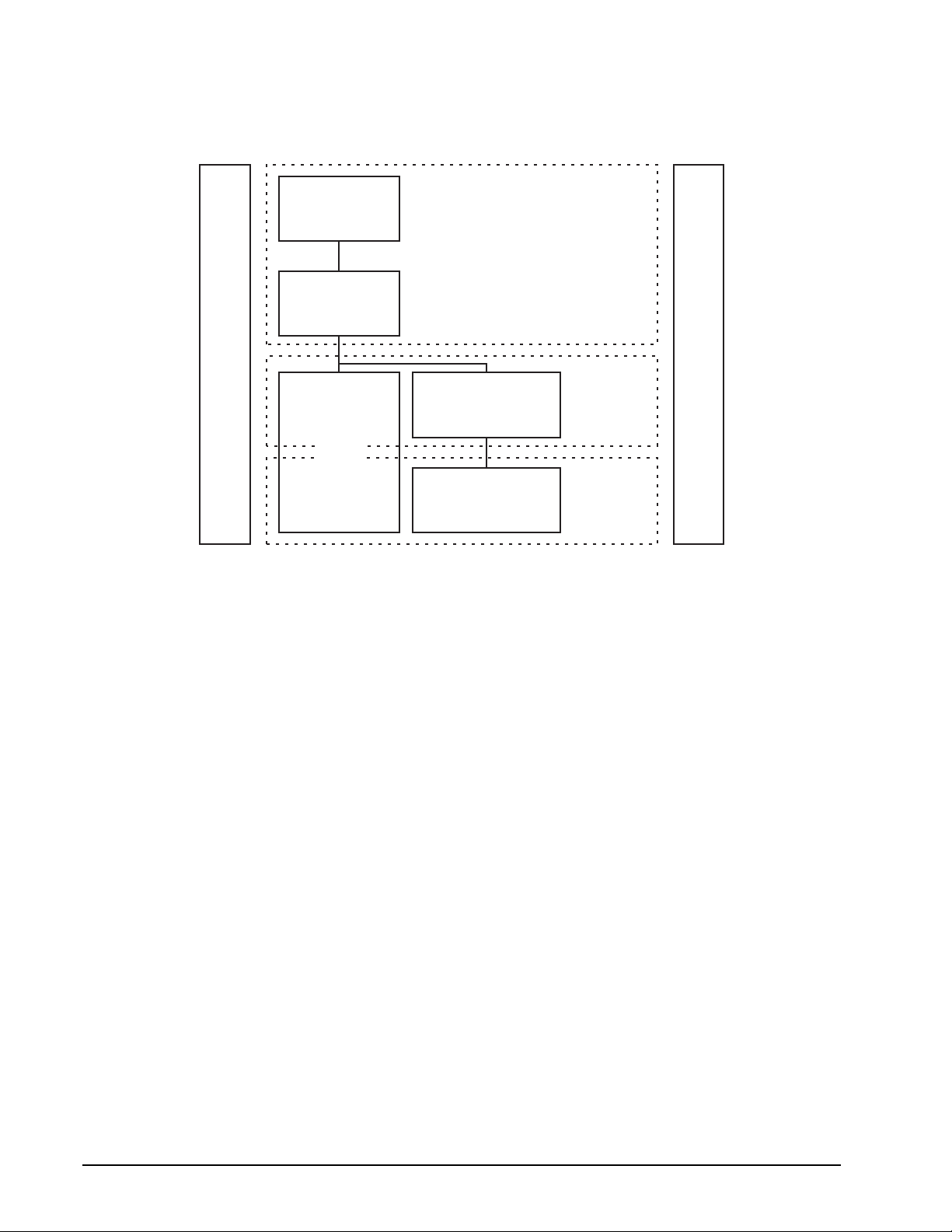
1.1.1 Scope of SCSI standards
Figure 1 uses a representative set of specifications to show the functional partitions and the relationships
among SCSI standards applicable to drives covered by this manual.
SCSI Block
Commands (SBC)
Commands
SCSI Primary
Commands (SPC)
SCSI
Interlocked
Protocol
SCSI Architecture Model (SAM)
Figure 1. Functional scope of SCSI1 standards
and
SCSI
Parallel
Interface (SPI-3)
Physical and Signaling
SCSI
Fibre Channel
Protocol (FCP)
Fibre Channel
Interface (FC-PH)
Protocols
Common Access Method (CAM)
Interconnects
The functional areas define the scope of each standard as follows:
• SCSI Architecture Model: Defines the SCSI systems model, the functional partitioning of the SCSI standard
set and requirements applicable to all SCSI implementations and implementation standards.
• Commands: Implementation standards which define classes including a device model for each class. These
standards specify the required commands and behavior that is common to all devices or unique to a given
class of devices and prescribe the rules to be followed by a SCSI initiator port when sending commands to a
device.
• Common Access Method: Implementation standard which defines a host architecture and set of services for
device access.
• Protocols: Implementation standards which define the rules for exchanging information so that different
SCSI devices can communicate.
• Interconnects: Implementation standards which define the electrical and signaling rules essential for devices
to interoperate over a given physical interconnect.
1
The diagram of Figure 1 shows how the standards listed below fit within each category. The standards
included in the diagram are meant to serve as examples and may not reflect the full set of standards currently
in force.
2 Parallel SCSI Interface Product Manual, Rev. A
Page 17

1.1.2 Applicable standards
The following ANSI standards should be referenced for more details about SCSI system standards of operation:
• SCSI Architecture Model - 4 (SAM-4), T10/1683-D
• SCSI Enclosure Services - 2 (SES-2), T10/1559-D
• SCSI Block Commands - 3 (SBC-3), T10/1215-D
• SCSI Primary Commands - 4 (SPC-4), T10/1731-D
• SCSI Enhanced Parallel Interface (EPI), T10/1143-DT
• SCSI Parallel Interface (SPI-5), T10/1525D
• SCSI Medium Changer Commands - 3 (SMC-3), T10/1730-D
• SCSI Controller Command Set - 2 (SCC-2), T10/1225D
• SCSI Stream Command - 3 (SSC-3), T10/1611-D
1.2 General interface description
This Parallel SCSI Interface Manual describes the Seagate Technology LLC. subset of the SCSI (Small Computer Systems Interface) as implemented on the Seagate-built drives. The interface is compatible with the
SCSI Interface Specifications listed in Section
ligent” peripherals.
The Seagate SCSI interface described herein consists of a 9 or 18 bit bidirectional data bus (includes bits for
parity checking and enabling CRC protection), plus 9 control signals. The SCSI interface supports multiple ini
tiators, disconnect/reconnect, self-configuring host software, automatic features that relieve the host from the
necessity of knowing the physical architecture of the target (logical block addressing is used), and some other
miscellaneous features.
1.1.2. The drives covered by this manual are classified as “Intel-
-
The SCSI physical interface uses either single-ended drivers and receivers or low voltage differential drivers
and receivers and uses asynchronous or synchronous communication protocols. The bus interface transfer
rate for asynchronous or synchronous is given in individual drive’s Product Manual. The bus protocol supports
multiple initiators, disconnect/reconnect, additional messages plus 6-byte, 10-byte, 12-byte, 16-byte and vari
able length Command Descriptor Blocks.
Unless specified otherwise in the individual drive’s Product Manual, the drive is always a SCSI target port, and
never a SCSI initiator port. For certain commands, which may or may not be supported by a particular drive
model, the drive must act as a SCSI initiator port, but does not otherwise do so. For purposes of this specifica
tion, “drive” may be substituted for the word “target” wherever “target” appears.
In the event of a conflict between this document and ANSI SCSI documents, the requirements of the ANSI documents shall apply.
Note. In this revision, some new terminology is introduced as taken from the ANSI specifications. In many
instances, the broader scope terms such as “initiator” and “target” are not used, but rather the more
specific terms “Application Client” and “Device Server” appear. In Figure
“application clients” from a single initiator may have one or more tasks in queue with several “device
servers” in a single target. A drive could be a SCSI target port or it could be one of the device servers
as part of some larger entity. When reading the description, one needs to be able to put the drive of
interest in the proper context in terms of what is shown in Figure
operation of the SCSI protocol, the terms in the SCSI architectural model as described in ANSI specification T10/1683-D (SAM-4) should be well understood before reading operation descriptions in any
SCSI document. Although a Glossary of terms is provided herein, the definitions may not be adequate
for some. The SAM-4 specification gives a more detailed understanding of some of the new SCSI ter
minology
2. For a proper understanding of the
2, it can be seen that several
-
-
-
Parallel SCSI Interface Product Manual, Rev. A 3
Page 18
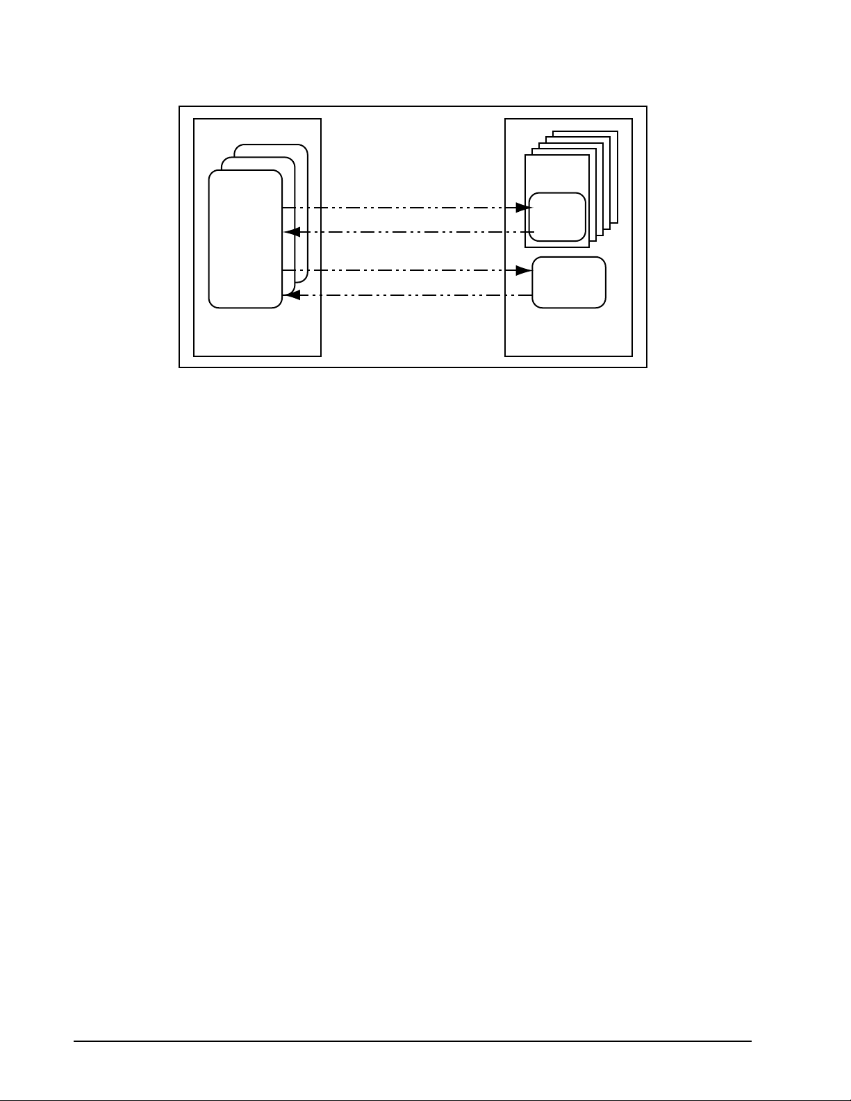
Application
Client
Device Service Request
Device Service Response
Task Management Request
Task Management Response
Logical
Unit
Device
Server
Task
Manager
Initiator
Figure 2. SCSI client-server model
Target
1.2.1 Glossary
aborted command—A SCSI command that has been ended by aborting the task created to execute it.
ACA—Auto Contingent Allegiance (see below).
additional sense code—a combination of the ADDITIONAL SENSE CODE and ADDITONAL SENSE CODE
QUALIFIER in the sense data (see SPC-4)
application client—An object that is the source of SCSI commands. An object in this sense is not a tangible
piece of hardware, but may be a single numeric parameter, such as a logical unit number, or a complex entity
that performs a set of operations or services on behalf of another object (see ANSI SAM-4, T10/1683-D).
asynchronous event notification—A procedure used by targets to notify initiators of events that occur when
a pending task does not exist for that initiator.
asynchronous transfer—An information transfer that uses the REQ/ACK handshake with an offset of zero.
auto contingent allegiance (ACA)—One of the conditions of a task set following the return of a CHECK
CONDITION status. See Section
4.4.2.
blocked task state—The state of a task that is prevented from completing due to an ACA condition.
blocking boundary—A task set boundary denoting a set of conditions that inhibit tasks outside the boundary
from entering the Enabled state.
byte—An 8-bit construct.
call—The act of invoking a procedure.
client-server—A relationship established between a pair of distributed objects where one (the client) requests
the other (the server) to perform some operation or unit of work on the client’s behalf (see SAM-4).
client—An object that requests a service from a server.
command—A request describing a unit of work to be performed by a device server.
4 Parallel SCSI Interface Product Manual, Rev. A
Page 19

command descriptor block—A structure used to communicate a command from an application client to a
device server. Command structures of 6, 10, 12, or 16 bytes are used, but a new variable length command
structure has recently been introduced.
completed command—A command that has ended by returning a status and service response of Task Complete or Linked Command Complete.
completed task—A task that has ended by returning a status and service response of Task Complete. The
actual events comprising the Task Complete response are protocol specific.
confirmation—A response returned to an object, which signals the completion of a service request.
confirmed service—A service available at the protocol service interface, which requires confirmation of com-
pletion. The confirmed service consists of the request and confirmation steps and optionally the indication and
response steps.
contingent allegiance (CA)—An optional condition of a task set following the return of a CHECK CONDITION
status. A detailed definition of contingent allegiance may be found in Section
SAM-4, ACA supported by SAM-4)
control mode page—The mode page that identifies the settings, and provides control, of several device
server behaviors that may be of interest to an application client or may be changed by an application client.
The complete definition of the Control mode page is found in the Seagate SCSI Command Reference Manual,
Part number 100293068, or SPC-4.
current task—A task that is in the process of sending messages, sending status, transferring data, or transferring command data to or from the initiator.
4.4.2. (CA declared obsolete by
cyclic redundancy check (CRC)—An error detecting code used to detect the validity of data that has been
transferred during the current data group.
data field—The portion of a data group that contains data bytes.
data group—A sequence of data bytes and the four pCRC bytes during a DT DATA IN PHASE or a DT DATA
OUT PHASE that starts at the first byte of the DT DATA phase or at the first byte after the last pCRC byte.
data group transfer—Parallel transfers that transfer data and pCRC information using only data groups. The
last four bytes of a data group transfer contain CRC information over the whole data group.
destination device—The SCSI device to which a service delivery transaction is addressed. See source
device.
device server—An object within the logical unit which executes SCSI tasks according to the rules for task
management described in clause 7 of ANSI SAM-4 document, T10/1683-D.
device service request—A request, submitted by an application client, conveying a SCSI command to a
device server.
device service response—The response returned to an application client by a device server on completion of
a SCSI command.
differential—A signalling alternative that employs differential (two complementary signals) drivers and receivers to improve signal-to-noise ratios and increase maximum cable lengths.
disconnect—The action that occurs when a SCSI device releases control of the SCSI bus, allowing it to go to
the BUS FREE PHASE.
domain—An I/O system consisting of a set of SCSI devices that interact with one another by means of a service delivery subsystem.
dormant (task state)—The state of a task that is prevented from starting execution due to the presence of certain other tasks in the task set.
Parallel SCSI Interface Product Manual, Rev. A 5
Page 20

double transition (DT)—The latching of data on both the assertion edge and the negated edge of the REQ or
ACK signals.
driver—The circuitry used to control the state of the bus.
enabled task state—The state of a task that may complete at any time. Alternatively, the state of a task that is
waiting to receive the next command in a series of linked commands.
ended command—A command that has completed or aborted.
exception condition—Any event that causes a SCSI device to enter an auto contingent allegiance or contin-
gent allegiance condition.
faulted initiator—The initiator to which a Command Terminated or CHECK CONDITION status was returned.
faulted I_T nexus: The I_T nexus on which a CHECK CONDITION status was returned that resulted in the
establishment of an ACA. The faulted I_T nexus condition is cleared when the ACA condition is cleared.
faulted task set: A task set that contains a faulting task. The faulted task set condition is cleared when the
ACA condition resulting from the CHECK CONDITION status is cleared.
faulting command: A command that completed with a status of CHECK CONDITION that resulted in the
establishment of an ACA.
faulting task: A task that has completed with a status of CHECK CONDITION that resulted in the establishment of an ACA.
function complete—A logical unit response indicating that a task management function has finished. The
actual events comprising this response are protocol specific.
hard reset—a SCSI target port response to a reset event or a SCSI target port Reset in which the target performs the operations described in Section 7.6.7.
implementation—The physical realization of an object.
implementation-specific—A requirement or feature that is defined in a SCSI standard but whose implemen-
tation may be specified by the system integrator or vendor.
implementation option—An option whose actualization within an implementation is at the discretion of the
implementor.
indication—The second step in a four-step confirmed service reply to a request.
information unit transfer—Parallel transfers that transfer data, status, commands, task attributes, task man-
agement information, acrid, and nexus information using only SPI information units.
initial connection—The result of a physical connect. It exists from the assertion of the BSY signal in a
SELECTION PHASE until the next BUS FREE PHASE or the next QAS REQUEST message.
initiator—A SCSI device containing application clients which originate device service and task management
requests to be processed by a SCSI target port SCSI device.
interconnect—The electrical media (including connectors and passive loads) used to connect the TERMPWR, terminators, and SCSI devices in a SCSI bus.
interconnect subsystem—One or more physical interconnects which appear as a single path for the transfer
of information between SCSI devices in a domain.
intersymbol interference (ISI)—The effect of adjacent symbols on the symbol currently being received.
in transit—Information that has been sent to a remote object but not yet received.
6 Parallel SCSI Interface Product Manual, Rev. A
Page 21

I/O operation—An operation defined by an unlinked SCSI command, a series of linked SCSI commands or a
task management function.
I/O process—An I/O process consists of one initial connection or, if information units are enabled, the
establishment of a nexus, and a zero or more physical or logical reconnection all pertaining to a single task or
a group of tasks. An I/O process begins with the establishment of a nexus. If the SPI information unit transfers
are disabled, an I/O process normally ends with a Command Complete message. If information unit transfers
are enabled, an I/O process ends with a SPI L_Q information unit with the type field set to status and the Data
Length field set to zero.
I_T nexus—A nexus that exists between a SCSI initiator port and a SCSI target port.
I_T_L nexus—A nexus that exists between a SCSI initiator port, a SCSI target port, and a logical unit. This
relationship replaces the prior I T nexus.
I_T_L_Q nexus—A nexus between a SCSI initiator port, a SCSI target port, a logical unit, and a queue tag following the successful receipt of one of the queue tag messages. This relationship replaces the prior I T L
nexus.
iuCRC protection—The use of CRC to detect DT DATA PHASE data transmission errors during parallel transfers. Contains CRC information covering all bytes transmitted in a SPI information unit.
layer—A subdivision of the architecture constituted by subsystems of the same rank.
linked CDB—A CDB with the link bit in the control byte set to one.
linked command—One in a series of SCSI commands executed by a single task, which collectively make up
a discrete I/O operation. In such a series, each command has the same task identifier, and all except the last
have the link bit in the CDB control byte set to one.
logical connect—Establishes an I_T_L_Q nexus using SPI L_Q information units.
logical disconnect—Reduces the current I_T_L_Q nexus to an I_T nexus.
logical reconnect—Reestablishes an I_T_L_Q nexus from an I_T nexus using SPI L_Q information units.
logical unit—a SCSI target port-resident entity which implements a device model and executes SCSI com-
mands sent by an application client.
logical unit number—A 64-bit identifier for a logical unit.
logical unit option—An option pertaining to a logical unit, whose actualization is at the discretion of the logical
unit implementor.
logical unit reset— A logical unit action in response to a logical unit reset event in which the logical unit performs the operations described in SCSI Architecture Model-4.
lower level protocol—A protocol used to carry the information representing upper level protocol transactions.
mandatory—The referenced item is required to claim compliance with a standard.
media information—Information stored within a SCSI device which is non-volatile (retained through a power
cycle) and accessible to a SCSI initiator port through the execution of SCSI commands.
multidrop—A characteristic of the SCSI bus that allows SCSI devices to be connected to the SCSI bus without disrupting the electrical path between the terminators.
multimode single-ended (MSE)—A signalling alternative for LVD SCSI devices that combines LVD SCSI and
single-ended SCSI (see SPI-5, SCSI parallel interface electrical characteristics) drivers and receivers to allow
operation when SE SCSI devices are present on the bus.
Parallel SCSI Interface Product Manual, Rev. A 7
Page 22

nexus—A relationship between a SCSI initiator port and a SCSI target port, logical unit, or queue tag that
begins with an initial connection and ends with the completion of the associated I/O process. This relationship
is formed as the result of a task.
object—An architectural abstraction or “container” that encapsulates data types, services, or other objects that
are related in some way.
odd parity—Odd logical parity, where the parity bit is driven and verified to be that value that makes the number of assertions on the associated data byte plus the parity bit equal to an odd number (1, 3, 5, 7, or 9). See
parity bit. If an even number of asserted bits are detected at the receiver, a parity error occurs.
paced transfer—Parallel transfers that transfer information using pacing.
pacing—Use of the ACK or REQ signal as a continuously running clock in combination with the P1 signal to
indicate when data is valid.
packetized—A method of transferring information using SPI information units. See object.
pad field—The portion of a data group that contains pad information.
parallel protocol request—Messages used to negotiate a synchronous data transfer agreement, a wide data
transfer agreement, and set the protocol options between two SCSI devices.
parity bit—A bit associated with a byte that is used to detect the presence of an odd number of asserted bits
within the byte. The parity bit is driven such that the number of logical ones in the byte plus the parity bit is odd.
pCRC field—The portion of a data group that contains pCRC information.
pCRC protection—The use of pCRC to detect DT DATA PHASE.
peer-to-peer protocol service—A service used by an upper level protocol implementation to exchange infor-
mation with its peer.
peer entities—Entities within the same (protocol) layer.
pending task—A task that is not a current task.
physical interconnect—A single physical pathway for the transfer of information between SCSI devices in a
domain.
physical reconnect—The act of resuming a nexus to continue a task. A SCSI target port initiates a physical
reconnect when conditions are appropriate for the physical bus to transfer data associated with a nexus
between a SCSI initiator port and a SCSI target port.
physical reconnection—The result of a physical reconnect that exists from the assertion of the BSY signal in
a SELECTION or RESELECTION PHASE. A physical reconnection ends with the BUS FREE PHASE (see
Section
port—Synonymous with “service delivery port.” A single attachment to a SCSI bus from a SCSI device.
procedure—An operation that can be invoked through an external calling interface.
protocol—The rules governing the content and exchange of information passed between distributed objects
through the service delivery subsystem.
protocol option—An option whose definition within a SCSI protocol standard is discretionary.
3.1.1) or a QAS REQUEST message (see Section 4.3.13).
protocol service confirmation—A signal from the lower level protocol service layer notifying the upper layer
that a protocol service request has completed.
protocol service indication—A signal from the lower level protocol service layer notifying the upper level that
a protocol transaction has occurred.
8 Parallel SCSI Interface Product Manual, Rev. A
Page 23

protocol service request—A call to the lower level protocol service layer to begin a protocol service transaction.
protocol service response—A reply from the upper level protocol layer in response to a protocol service indication.
quick arbitration and selection process (QAS)—Quicker than the normal arbitration and selection process.
Implementation is optional for SCSI devices.
queue—The arrangement of tasks within a task set, usually according to the temporal order in which they were
created. See task set.
queue tag—The parameter associated with a task that uniquely identifies it from other tagged tasks for a logical unit from the same initiator.
receiver—A client or server that is the recipient of a service delivery transaction.
reference model—A standard model used to specify system requirements in an implementation-independent
manner.
request—A transaction invoking a service.
request-response transaction—An interaction between a pair of distributed, cooperating objects, consisting
of a request for service submitted to an object followed by a response conveying the result.
request-confirmation transaction—An interaction between a pair of cooperating objects, consisting of a
request for service submitted to an object followed by a response for the object confirming request completion.
reset event—A protocol-specific event which may trigger a hard reset response from a SCSI device as
described in Section
response—A transaction conveying the result of a request.
SCSI application layer (SAL)—The protocols and procedures that implement or invoke SCSI commands and
task management functions by using services provided by a SCSI protocol layer.
SCSI device—A device that contains at least one SCSI port and the means to connect its drivers and receivers to the bus.
SCSI device identifier—An address by which a SCSI device is referenced within a domain.
SCSI I/O system—An I/O system, consisting of two or more SCSI devices, a SCSI interconnect and a SCSI
protocol, which collectively interact to perform SCSI I/O operations.
SCSI protocol layer—The protocol and services used by a SCSI application layer to transport data representing a SCSI application protocol transaction.
sender—A client or server that originates a service delivery transaction.
server—A SCSI object that performs a service on behalf of a client.
service—Any operation or function performed by a SCSI object, which can be invoked by other SCSI objects.
service delivery failure—Any non-recoverable error causing the corruption or loss of one or more service
delivery transactions while in transit.
5.3.
service delivery port—A device-resident interface used by the application client, device server or task manager to enter and retrieve requests and responses from the service delivery subsystem. Synonymous with
“port.”
service delivery subsystem—That part of a SCSI I/O system which transmits service requests to a logical
unit or target and returns logical unit or target responses to a SCSI initiator port.
Parallel SCSI Interface Product Manual, Rev. A 9
Page 24

service delivery transaction—A request or response sent through the service delivery subsystem.
signal—(n) A detectable asynchronous event possibly accompanied by descriptive data and parameters. (v)
The act of generating such an event.
single transition (ST)—The latching of data only on the assertion edge of the REQ or ACK signals.
source device—The SCSI device from which a service delivery transaction originates. See destination device.
SPI information unit—Data structures that encapsulate data, status, command, task attributes, iuCRC, and
nexus information into various formats.
SPI L_Q information unit—The SPI L_Q information unit (see Section 6.2.2, tables 49 and 50) contains L_Q
nexus (Logical unit—Q tag relationship) information for the information unit that follows, the type of information
unit that follows, and the length of information unit that follows. A SPI L_Q information unit shall precede all SPI
command information units, SPI multiple command information units, SPI data information units, SPI status
information units, and the first of an uninterrupted sequence of SPI data stream information units.
subsystem—An element in a hierarchically partitioned system which interacts directly only with elements in
the next higher division or the next lower division of that system.
suspended information—Information stored within a logical unit that is not available to any pending tasks.
target—A SCSI device which receives SCSI commands and directs such commands to one or more logical
units for execution.
task—An object within the logical unit representing the work associated with a command or group of linked
commands. A task consists of one initial connection and zero or more physical or logical reconnections, all per
taining to the task.
-
task abort event—An event or condition indicating that the task has been aborted by means of a task management function.
task address—a SCSI initiator port identifies a task to a SCSI target port using a Task Address. The Task
Address object represents either a Tagged Task Address or an Untagged Task Address without regard for the
tagged or untagged nature of the Task. A Tagged Task Address is composed of a Logical Unit Identifier and a
Tag. An Untagged Task Address is composed of a Logical Unit Identifier.
task completion event—An event or condition indicating that the task has ended with a service response of
Task Complete.
task ended event—An event or condition indicating that the task has completed or aborted.
task management function—A task manager service which can be invoked by an application client to affect
the execution of one or more tasks.
task management request—A request submitted by an application client, invoking a task management func-
tion to be executed by a task manager.
task management response—The response returned to an application client by a task manager on completion of a task management request.
task manager—A server within the target which executes task management functions.
task set—A group of tasks within a SCSI target port device, whose interaction is dependent on the queuing
and auto contingent allegiance rules of Section
task slot—Resources within the logical unit that may be used to contain a task.
7.6.1.
task tags—A Tag is a field containing up to 64 bits that is a component of a Tagged Task Identifier. A SCSI initiator port assigns tag values in each Tagged Task Identifier in a way that ensures that the identifier uniqueness
requirements stated in ANSI SAM-4, T10/1683-D, are met.
10 Parallel SCSI Interface Product Manual, Rev. A
Page 25

third-party command—A SCSI command which requires a logical unit within the target device to assume the
initiator role and send a SCSI command to a SCSI target port device.
transaction—A cooperative interaction between two objects, involving the exchange of information or the execution of some service by one object on behalf of the other.
transfer period—The negotiated time between edges of REQ or ACK that latch data. For ST, the transfer
period is measured from assertion edge of the REQ or ACK signal to the next assertion edge of the signal. For
DT, the transfer period is measured from a transition edge of the REQ or ACK signal to the next transition edge
of the signal.
unconfirmed protocol service—A service available at the protocol service interface, which does not result in
a completion confirmation.
unlinked command—A SCSI command having the link bit set to zero in the CDB control byte.
upper level protocol—An application-specific protocol executed through services provided by a lower level
protocol.
1.2.2 Keywords
Several keywords are used to differentiate between different levels of requirements and optionality, as follows:
vendor-specific—Specification of the referenced item is determined by the device vendor.
protocol-specific—Implementation of the referenced item is defined by a SCSI protocol standard (see Sec-
tion 1.1.1.)
expected—A keyword used to describe the behavior of the models specified by this standard.
invalid—A keyword used to describe an illegal or unsupported bit, byte, word, field, or code value. Receipt of
an invalid bit, byte, word, field, or code value shall be reported as an error.
mandatory—A keyword indicating items required to be implemented as defined by this standard.
may—A keyword that indicates flexibility of choice with no implied preference (equivalent to “may or may not”).
may not—Keywords that indicates flexibility of choice with no implied preference (equivalent to “may or may
not”).
obsolete—A keyword indicating items that were defined in prior SCSI standards but have been removed from
this standard.
option, optional—Keywords that describe features which are not required to be implemented by this standard. However, if any optional feature defined by the standard is implemented, it shall be implemented as
defined by the standard.
reserved—A key word referring to bits, bytes, words, fields, and code values that are set aside for future standardization. Their use and interpretation may be specified by future extensions to this or other standards. A
reserved bit, byte, word, or field shall be set to zero, or in accordance with a future extension to this standard.
Recipients are not required to check reserved bits, bytes, words, or fields for zero values. Receipt of reserved
code values in defined fields shall be treated as an error.
shall—A keyword indicating a mandatory requirement. Designers are required to implement all such mandatory requirements to ensure interoperability with other standard conformant products.
should—A keyword indicating flexibility of choice with a strongly preferred alternative. Equivalent to the
phrase “it is recommended.”
Parallel SCSI Interface Product Manual, Rev. A 11
Page 26

1.3 Physical interface characteristics
The physical interface characteristics (cables, connectors, electrical descriptions, termination requirements,
etc.) for the drives covered by this Interface Manual are found in each individual drive’s Product Manual, since
these features are not the same for all drives.
1.4 Summary of SCSI messages
Following is an alphabetical summary of the SCSI messages described in this manual. Details are given in
Section
Message Name Hex Code Page number
ABORT TASK 06 105
CLEAR QUEUE 0E 106
DISCONNECT 04 87
EXTENDED MESSAGE 01 84
IDENTIFY 80-FF 87
IGNORE WIDE RESIDUE 23 88
INITIATE RECOVERY 0F Not described in this manual
INITIATOR DETECTED ERROR 05 89
MESSAGE PARITY ERROR 09 89
MESSAGE REJECT 07 89
MODIFY DATA POINTER 01, 05, 00 89 (extended message)
NO OPERATION 08 91
PARALLEL PROTOCOL REQUEST 01, 06, 04 92
QAS REQUEST 55 96
RELEASE RECOVERY 10 Not described in this manual
RESTORE POINTERS 03 96
SAVE DATA POINTERS 02 96
SYNCHRONOUS DATA TRANSFER REQUEST 01, 03, 01 97 (extended message)
TASK ATTRIBUTE MESSAGES 102
ACA (AUTO CONTINGENT
ALLEGIANCE)
HEAD OF QUEUE TAG 21 104
LINKED COMMAND COMPLETE 0A 89
ORDERED QUEUE TAG 22 104
SIMPLE QUEUE TAG 20 104
TASK COMPLETE 00 99
TASK MANAGEMENT MESSAGES 105
ABORT TASK 00 105
ABORT TASK SET 06 106
CLEAR ACA 16 106
CLEAR TASK SET 0E 106
LOGICAL UNIT RESET 17 106
TARGET RESET 0C 106
WIDE DATA TRANSFER REQUEST 01, 03 100 (extended message)
4.
24 103
12 Parallel SCSI Interface Product Manual, Rev. A
Page 27

2.0 SCSI bus
This manual discusses only the “logical” and timing characteristics of the SCSI system and interface. A general
description of the SCSI bus physical characteristics (voltages, connector configurations, pinouts, etc.) are
given in the individual drive’s Product Manual, in the “Interface requirements” section, which covers the inter
face requirements and SCSI features supported by the drive described in the particular Product Manual being
referenced. For all of the physical details of the SCSI interface, consult the ANSI standards referenced in Sec
tion 1.1.2.
Communication on the SCSI Bus is allowed between only two SCSI devices at a time. Seagate drives support
systems with a maximum of 16 SCSI devices including the host computer(s) connected to the SCSI bus. Each
SCSI device has a SCSI ID bit assigned as shown in Table
plugs onto a connector in a binary coded configuration during system configuration. Some drive models have
an interface that includes the SCSI bus ID lines, so that the host can set the drive ID over the interface (see
individual drive’s Product Manual, “Option/configuration headers” section).
When two SCSI devices communicate on the SCSI Bus, one acts as a SCSI initiator port and the other acts as
a SCSI target port. The initiator (typically a host computer) originates an I/O process and the target performs
whatever operations/tasks are called for by the I/O process. Devices arbitrate to get control of the bus to per
form whatever communications are required by the current I/O process. As part of the arbitration process,
devices on the SCSI bus assert their bus ID (one of the DB lines as shown in Table
is discussed in more detail later. Devices supported by this interface specification always operate as targets,
unless otherwise specified (i.e., if certain commands are supported) in the individual drive’s Product Manual,
Volume 1.
1. The SCSI ID is assigned by installing 0-3 jumper
1). The arbitration process
-
-
-
Parallel SCSI Interface Product Manual, Rev. A ) 13
Page 28

Table 1: SCSI IDs and associated SCSI bus arbitration priorities
SCSI
addressDB15
7 - - - - - - - - 1 - - - - - - - 1
6 - - - - - - - - - 1 - - - - - - 2
5 - - - - - - - - - - 1 - - - - - 3
4 - - - - - - - - - - - 1 - - - - 4
3 - - - - - - - - - - - - 1 - - - 5
2 - - - - - - - - - - - - - 1 - - 6
1 - - - - - - - - - - - - - - 1 - 7
0 - - - - - - - - - - - - - - - 1 8
15 1 - - - - - - - - - - - - - - - 9
14 - 1 - - - - - - - - - - - - - - 10
13 - - 1 - - - - - - - - - - - - - 11
12 - - - 1 - - - - - - - - - - - - 12
11 - - - - 1 - - - - - - - - - - - 13
10 - - - - - 1 - - - - - - - - - - 14
DB8DB
7
DB
0
Priority
9 - - - - - - 1 - - - - - - - - - 15
8 - - - - - - - 1 - - - - - - - - 16
Key: - = a logical 0 bit resulting from the data bus bit being released
The Host Adapter/Initiator must be identified by one of the 16 SCSI Device IDs (usually 7, which is highest arbitration priority). Make sure that none of the devices on the SCSI bus have duplicate IDs.
Certain SCSI bus functions are assigned to the initiator and certain SCSI bus functions are assigned to the target. The initiator will select a particular target. The target will request the transfer of Command, Data, Status, or
other information on the data bus.
Under SCSI-2 protocol, information transfers on the data bus are interlocked and follow a defined REQ/ACK
Handshake protocol. One byte of information will be transferred with each handshake. Synchronous data
transfers do not require a one-for-one interlocking of REQ/ACK signals, but the total number of REQ pulses in
a particular data transfer event must equal the total number of ACK pulses. The synchronous data transfer
option is described in Paragraphs 3.1.5.2 and 3.5.3.2 of the Ultra2 SCSI Interface Manual, part number
77738479.
This Ultra160/Ultra320 Parallel SCSI Interface Manual, discusses SCSI-3 protocol (now called only “SCSI”).
There are now different ways of latching data from the REQ and ACK signals, depending on whether ST DATA
phases, DT DATA phases, or paced transfers are being used for information transfers. This is described in
Section
2.1.2.
The drive supports single initiator, single target; single initiator, multiple target; multiple initiator, single target; or
multiple initiator, multiple target bus configurations.
14 Parallel SCSI Interface Product Manual, Rev. A )
Page 29

2.1 SCSI bus signals overview
Information transfer on the SCSI bus is allowed between only two SCSI devices at any given time except during MESSAGE IN PHASE when QAS is enabled. All SCSI devices that have QAS enabled are required to
monitor messages during a MESSAGE IN PHASE for a QAS REQUEST MESSAGE. The maximum number of
SCSI devices is determined by the width of the data path implemented. The SCSI devices may be any combi
nation of SCSI initiator ports (commonly called “initiators”) and SCSI target ports (commonly called “targets”),
provided there is at least one of each.
Each SCSI device has a SCSI address and a corresponding SCSI ID bit assigned to it. When two SCSI
devices communicate on the SCSI bus, one acts as the initiator and the other acts as the target. The initiator
originates an I/O process and the target receives the I/O process.
Some drive models have a single 80-pin I/O connector that contains additional interface lines that carry drive
configuration select signals. These are peculiar to certain drives and are not SCSI standard signals. These are
described in the individual drive’s product manual, Volume 1.
The 28 SCSI standard signals are described as follows:
BSY (Busy)—An “OR-tied” signal to indicate the bus is being used.
SEL (Select)—An “OR-tied” signal used by a SCSI initiator port to select a SCSI target port, or by a SCSI tar-
get port to reselect a SCSI initiator port.
RST (Reset)—An “OR-tied” signal that indicates the bus reset condition (see Section 5.2).
C/D (Control/Data)—A signal sourced by a SCSI target port that indicates whether CONTROL or DATA
PHASE information is on the data bus. Assertion indicates Control (i.e., COMMAND, STATUS, and MESSAGE
phases).
-
I/O (Input/Output)—A signal sourced by a SCSI target port to control the direction of data movement on the
Data Bus with respect to a SCSI initiator port. Assertion indicates input to the initiator. This signal also distin
guishes between SELECTION and RESELECTION phases.
MSG (Message)—A signal sourced by a SCSI target port to indicate the MESSAGE phase or a DT DATA
phase depending on whether C/D is true or false. Asserted indicates MESSAGE or DT DATA.
REQ (Request)—A signal sourced by a SCSI target port to indicate a request for an information transfer on the
SCSI bus.
ACK (Acknowledge)—A signal sourced by a SCSI initiator port to respond with an acknowledgment of an
information transfer on the SCSI bus.
ATN (Attention)—A signal sourced by a SCSI initiator port to indicate the Attention condition.
DIFFSENS (Differential Sense)/Multimode—SE or LVD alternative— “LW” and “LC” models have I/O cir-
cuits that can operate either in single-ended (SE) or low voltage differential (LVD) mode. When the interface
DIFFSENS line is between -0.35 V and +0.5 V, the drive interface circuits operate single-ended. When DIFFS
ENS is between +0.7 V and +1.9 V, the drive interface circuits operate low voltage differential. This arrangement is not intended to allow dynamically changing transmission modes, but rather to prevent incompatible
devices from attempting to interoperate. Drives must operate only in the mode for which the installation and
interface cabling is designed. Multimode I/O circuits used by “LW” and “LC” devices do not operate at high volt
age differential levels and should never be exposed to high voltage differential environments unless the command mode voltages in the environment are controlled to safe levels for single-ended and low voltage
differential devices (see the ANSI SPI-5 specification). High Voltage Differential (HVD) is now an obsolete
ANSI standard.
-
-
-
P_CRCA (Parity/CRC Available)—A signal identifying either parity or CRC available based on bus phase and
negotiated settings.
Parallel SCSI Interface Product Manual, Rev. A ) 15
Page 30

During the SELECTION PHASE, RESELECTION PHASE, ST DATA PHASE, COMMAND PHASE, MESSAGE
PHASE, and STATUS PHASE, this signal is referred to as DB(P_CRCA) and is sourced by the SCSI device
port driving the Data Bus. The DB(P_CRCA) signal is associated with the DB(7-0) signals and is used to detect
the presence of an odd number of bit errors within the byte. The DB(P_CRCA) bit is driven such that the num
ber of logical ones in the byte plus the parity bit is odd.
Data group transfers are enabled (see Section 4.3.12) when this signal is referred to as P_CRCA and is
sourced by the target to control whether a data group field is a pad field, pCRC field, or data field (see Section
2.11.1). When asserted, the data group field shall be pad or pCRC fields that shall not be transferred to the
application client. When negated, the data group field shall be a data field that shall be transferred to the application client.
During DT DATA phases when information unit transfers are enabled, this signal is referred to as P_CRCA and
sourced by the SCSI target. Depending on the negotiated condition of read streaming and write flow control,
the SCSI initiator and target usage for P_CRCA is different. When information unit transfers are enabled, the
SCSI target and initiator shall use the P_CRCA signal as indicated in Table
2.
Table 2: P_CRC signal usage requirements
SCSI initiator
Write flow
control
Disabled Disabled All Ignore Continuously negated.
Enabled Disabled DT DATA IN Ignore Continuously negated.
Read
streaming DT Data phase
response to
P_CRCA
SCSI target usage of P_CRCA
-
DT DATA OUT Monitor Asserts to indicate when the current SPI data stream
information unit is the last SPI data stream information
unit of the current write stream.
Disabled Enabled DT DATA IN Monitor Asserts to indicate when the current SPI data stream
information unit is the last SPI data stream information
unit of the current read stream.
DT DATA OUT Ignore Continuously negated.
Enabled Enabled DT DATA IN Monitor Asserts to indicate when the current SPI data stream
information unit is the last SPI data stream information
unit of the current read stream.
DT DATA OUT Monitor Asserts to indicate when the current SPI data stream
information unit is the last SPI data stream information
unit of the current read stream.
A SCSI device is not required to use read streaming even if it is enabled
A SCSI device is not required to use write flow control even if it is enabled
P1 (Parity 1)—A signal normally sourced by the SCSI device driving the Data Bus. The P1 signal is associated
with the DB(15–8) signals and is used to detect the presence of an odd number of bit errors within the byte The
P1 bit is driven such that the number of logical ones in the byte plus the P1 bit is odd.
During the ST DATA PHASE with transfer length set for 8-bit transfers, COMMAND PHASE, MESSAGE
PHASE, and STATUS phase, the P1 signal shall not be driven by any SCSI device.
During the SELECTION phase and the RESELECTION phase on a 16-bit wide bus segment the P1 signal
shall be sourced by the SCSI device driving the DATA BUS.
When data group transfers are enabled (see Section 4.3.12), the P1 signal shall be continuously negated by
the SCSI device driving the DB(15-0) signals and shall be ignored by the SCSI device receiving the DB(15-0)
signals during DT DATA phases.
16 Parallel SCSI Interface Product Manual, Rev. A )
Page 31

When information unit transfers are enabled, the P1 signal shall be continuously negated by the SCSI device
driving the DB(15-0) signals and shall be ignored by the SCSI device receiving the DB(15-0) signals during DT
DATA phases.
During DT DATA phases when information unit transfers and paced transfers are enabled the P1 signal shall
be sourced by the SCSI device driving the DATA BUS. The P1 signal is used to indicate the data valid or data
invalid state during paced transfers.
DB(7–0) (8-bit data bus)—Each data bit that forms the 8-bit data bus. Bit significance and priority during arbitration are shown in Table 1.
DB(15–0) (16-bit data bus)—16 data bit signals that form the 16-bit Data Bus. Bit significance and priority during arbitration are shown in Table 1.
Greater detail on each of the SCSI bus signals is found in the following sections.
2.1.1 Drive select
For SCSI ID selection, install drive select jumpers as shown in configuration selection figure in the individual
drive’s Product Manual. Refer to the “Physical interface” section of the individual drive’s Product Manual for the
location of the drive select header. Drives using the 8-bit data interface can have one of eight ID bits selected
by installing 0 through 2 (3) jumpers in a binary coded configuration on the drive select header. Drives using
the 16-bit data interface can have one of 16 ID bits selected by installing 0 through 3 (4) jumpers in a binary
coded configuration on the drive select header. “LC” model drives (80-pin direct connect I/O connector) can be
assigned their bus ID over the SCSI interface.
2.1.2 Signal values
Signals may assume true or false values. There are two methods of driving these signals. In both cases, the
signal shall be actively driven true, or asserted. In the case of OR-tied drivers, the driver does not drive the sig
nal to the false state, rather the bias circuitry of the bus terminators pulls the signal false whenever it is
released by the drivers at every SCSI device. If any driver is asserted, then the signal is true. In the case of
non-OR-tied drivers, the signal may be negated. Negated means that the signal may be actively driven false,
or may be simply released (in which case the bias circuitry pulls it false), at the option of the implementor.
2.2 Signal states
2.2.1 SE signals
Signals may be in a true (asserted) or false (negated) state. Signals that are asserted are actively driven to the
true state. Signals that are negated may either be actively driven to the false state or released to the false
state. A signal that is released goes to the false state because the bias of the terminator pulls the signal false.
OR-tied signals shall not be actively driven false.
Note. The advantage of actively negating signals false during information transfer is that the noise margin is
higher than if the signal is simply released. This facilitates reliable data transfer at high transfer rates.
Bits of the data bus are defined as one when the signal is true and defined as zero when the signal is false.
2.2.2 LVD signals
Figure 3 defines the voltage and current definitions. A signal that is released goes to the false state because
the bias of the terminator pulls the signal false.
-
Parallel SCSI Interface Product Manual, Rev. A ) 17
Page 32

I
)
–
– SIGNAL
V
s
V
–
V
+
+ SIGNAL
I
+
– TRANSCEIVER
Figure 3. Voltage and current definitions
Figure 4 defines the signaling sense of the voltages appearing on the – signal and + signal lines as follows:
a. The – signal terminal of the driver shall be negative with respect to the + signal terminal for an asserted
state.
b. The – signal terminal of the driver shall be positive with respect to the + signal terminal for a negated state.
LOGICAL 1
(ASSERTED)
(TRUE)
+
V
–
V
+
–V
–
V
DIFFERENTIAL BUS VOLTAGE
Figure 4. LVD Signaling sense
Note. For a description of V
BIAS
2.3 OR-tied signals
LOGICAL 0
(NEGATED)
(FALSE)
VCM=(V++V–)/2 V
LOGICAL 1
(ASSERTED)
(TRUE)
V
V
CM
N
BIAS
0V (OFF
V
A
TIME
see Section 7.3.1 of ANSI specification (SPI-5), T10/1525D.
The BSY, SEL, and RST signals shall be OR-tied. BSY and RST signals may be simultaneously driven true by
several SCSI devices. No signals other than BSY, SEL, RST, DB(P_CRCA), and DB(P1) are simultaneously
driven by two or more SCSI devices. DB(P_CRCA) and DB(P1) shall not be driven false during the ARBITRA
TION PHASE but may be driven false in other phases.
18 Parallel SCSI Interface Product Manual, Rev. A )
-
Page 33

2.4 Signal sources
Ta bl e 3 indicates the type of SCSI device allowed to source each signal. No attempt is made to show if the
source is driving asserted, driving negated, or is released. All SCSI device drivers that are not active sources
shall be in the high-impedance state. The RST signal may be asserted by any SCSI device at any time.
Table 3: Signal sources
16 data bit (P) cable
8 data bit (A) cable
C/D, I/O,
SCSI bus phase BSY SEL
BUS FREE None None None None None None None
ARBITRATION
(NORMAL)
QAS ARBITRATION PT Win None None S ID S ID S ID
SELECTION I & T Init None Init Init Init Init
RESELECTION I & T Ta rg Ta rg Init Ta rg Ta rg Ta rg
COMMAND Ta rg None Ta rg Init Init Init None
ST DATA IN Ta rg None Ta rg Init Ta rg Ta rg Ta rg
ST DATA OUT Ta rg None Ta rg Init Init Init Init
DT DATA IN Ta r g Tar g Ta rg Init Ta r g Tar g Ta r g
DT DATA OUT Tar g Ta rg Ta rg Init Init Ta rg Init
STATUS Ta rg None Ta r g Init Ta rg Ta rg None
All Win None None S ID S ID S ID
MSG, REQ ACK, ATN DB(7-0) P_CRCA
DB(15-8),
DB(P1)
MESSAGE IN Ta rg None Ta rg Init Ta r g Tar g None
MESSAGE OUT Tar g None Ta rg Init Init Init None
Table abbreviations are defined as follows:
All: The signal shall be driven by all SCSI devices that are actively arbitrating.
S ID: A unique data bit (the SCSI ID) shall be driven by each SCSI device that is actively arbitrating; the other
data bits shall be released (i.e., not driven) by this SCSI device. The P_CRCA and DB(P1) bit(s) may be
released or driven to the true state, but shall not be driven to the false state during this phase.
I&T: The signal shall be driven by the initiator, target, or both, as specified in the SELECTION PHASE and
RESELECTION PHASE.
Init: If driven, this signal shall be driven only by the active initiator.
None: The signal shall be released; that is, not driven by any SCSI device. The bias circuitry of the bus termi-
nators pulls the signal to the false state.
Win: The signal shall be driven by the one SCSI device that wins arbitration.
Targ: If the signal is driven, it shall be driven only by the active target.
PT: Target that initiated the QAS arbitration.
Parallel SCSI Interface Product Manual, Rev. A ) 19
Page 34

2.5 SCSI bus timing
Unless otherwise indicated, the delay time measurements for each SCSI device, defined in paragraphs 2.5.1
through 2.5.60 shall be calculated from signal conditions existing at that SCSI device’s own SCSI bus connection. Thus, these measurements (except skew delay) can be made without considering delays in the cable.
Refer to the tables below for the actual timing values for these delays.
Table 4: SCSI bus control timing values in nanoseconds
Timing
value (ns
unless
noted)
Timing description
Arbitration delay
Reference Typ e
2.5.1 minimum 2.4 µs
Bus clear delay
Bus free delay
Bus set delay
Bus settle delay
Cable skew [1]
Data release delay
DIFFSENS voltage filter time
Physical disconnection delay
Power on to selection [2]
QAS arbitration delay
QAS assertion delay
QAS release delay
QAS non-data phase REQ(ACK) period
Reset delay
Reset hold time
Reset to selection [2]
Selection abort time
Selection time-out delay [2]
2.5.4 maximum 800
2.5.5 minimum 800
2.5.6 maximum 1.6 µs
2.5.7 minimum 400
2.5.8 maximum 4
2.5.21 maximum 400
2.5.22 minimum 100 ms
2.5.24 minimum 200 µs
2.5.25 maximum 10 s
2.5.26 minimum 1000
2.5.27 maximum 200
2.5.28 maximum 200
2.5.29 minimum 50
2.5.42 minimum 200
2.5.43 minimum 25 µs
2.5.44 maximum 250 ms
2.5.46 maximum 200 µs
2.5.47 minimum 250 ms
System deskew delay
[1] Cable skew is measured at each SCSI device connection with the transmitted skew subtracted from the
2.5.51 minimum 45
received skew.
[2] This is a recommended time. It is not mandatory.
20 Parallel SCSI Interface Product Manual, Rev. A )
Page 35

Table 5: SCSI bus data and information phase ST timing values
Timing values for negotiated transfer rate in
nanoseconds unless otherwise noted [1]
Timing description Reference Ty pe
ATN transmit setup time
ATN receive setup time
Cable skew [2]
Receive assertion period [3]
Receive hold time [3] [4]
Receive negation period [3]
Receive setup time [3] [4]
Receive REQ(ACK) period tolerance
Signal timing skew
REQ(ACK) period
Transmit assertion period [2]
Transmit hold time [3] [4]
Transmit negation period [3]
Transmit setup time [3] [4]
Transmit REQ(ACK) period tolerance
2.5.2 min 90 33 33 21.5 19.25
2.5.3 min 45 17 17 8.5 6.75
2.5.8 max 4.0 4.0 4.0 3.0 2.5
2.5.30 min N/A 70 22 11 6.5
2.5.31 min N/A 25 25 11.5 4.75
2.5.34 min N/A 70 22 11 6.5
2.5.35 min N/A 15 15 6.5 4.75
2.5.36 min N/A 1.1 1.1 1.1 1.1
2.5.48 max 8.0 8.0 8.0 5.0 4.5
2.5.41 nom N/A 200 100 50 25
2.5.55 min N/A 80 30 15 8.0
2.5.56 min N/A 53 33 16.5 9.25
2.5.58 min N/A 80 30 15 8.0
2.5.59 min N/A 23 23 11.5 9.25
2.5.60 max N/A 1.0 1.0 1.0 1.0
Asynch Fast-5 Fast-10 Fast-20 Fast-40
[1] SCSI bus timing values specified by the maximum transfer rate for the given range shall apply even if a
slower transfer rate within the given range is negotiated.
[2] Cable skew is measured at each SCSI device connection within the same bus segment with the transmit-
ted skew subtracted from the received skew.
[3] See Section 2.6 for measurement points for the timing specifications.
[4] See Section 9.6 in the ANSI SCSI Parallel Interface-5 (SPI-5) specification for examples of how to calcu-
late setup and hold timing.
Table 6: Miscellaneous SCSI bus data and information phase DT timing values
Timing values for negotiated transfer rate in nanoseconds
unless otherwise noted [1]
Timing description Reference Type
Cable skew [2]
REQ(ACK) period
Residual skew error [3]
Skew correction range [4]
Signal timing skew
Strobe offset tolerance
[1] SCSI bus timing values specified by the maximum transfer rate for the given range shall apply even if a
2.5.8 max 4.0 3.0 2.5 2.5 2.5 2.5
2.5.41 nom 200 100 50 25 12.5 6.25
2.5.45 max N/A N/A N/A N/A
2.5.49 min N/A N/A N/A N/A
2.5.48 max 26.8 13.4 6.7 3.35 4.85 4.85
2.5.50 max N/A N/A N/A N/A
Fast-10 Fast-20 Fast-40 Fast-80 Fast-160 Fast-320
±0.15 ± 0.20
±3.45 [5] ± 3.45 [5]
±0.125 ±0.125
slower transfer rate within the given range is negotiated.
Parallel SCSI Interface Product Manual, Rev. A ) 21
Page 36

[2] Cable skew is measured at each SCSI device connection within the same bus segment with the transmit-
ted skew subtracted from the received skew.
[3] Calculated assuming timing budget shown in Table 9.
[4] Measured at the receiver terminal using clean input signals with 500 mV peak amplitude and 1 ns rise and
fall time between 20% and 80% of the signal.
[5] Relative to the REQ(ACK) clocking signal.
Note. Fast-160 SCSI devices shall not change timing parameters between training (see Section 3.5.3.1) or
reset events (see Section 5.4).
22 Parallel SCSI Interface Product Manual, Rev. A )
Page 37

Table 7: Transmit SCSI bus data and information phase DT timing values
Timing values for negotiated transfer rate in nanoseconds
unless otherwise noted
[1]
Timing description Reference Typ e
ATN transmit setup time
Flow control transmit hold time
Flow control transmit setup time
pCRC transmit hold time
pCRC transmit setup time
Transmit assertion period [2]
Transmit hold time [2] [3]
Transmit ISI compensation
Transmit negation period [2]
Transmit REQ(ACK) period toler-
2.5.2 min 48.4 29.2 19.6 14.8 14 14
2.5.15 min 38.4 19.2 9.6 4.8 14 14
2.5.16 min 48.4 29.2 19.6 14.8 14 14
2.5.19 min 38.4 19.2 9.6 4.8 N/A N/A
2.5.20 min 48.4 29.2 19.6 14.8 N/A N/A
2.5.55 min 92 46 23 11.5 5.69 2.565
2.5.56 min 38.4 19.2 9.6 4.8 4.77 0.365
2.5.57 max 1.0 0
2.5.58 min 92 46 23 11.5 5.69 2.565
2.5.60 max 0.6 0.6 0.6 0.6 0.06 0.06
ance
Transmit REQ assertion period
2.5.61 min 97.5 54 35.5 24 N/A N/A
with P_CRCA transitioning
Transmit setup time [2] [3]
Transmitter skew
Transmitter time asymmetry
2.5.59 min 38.4 19.2 9.6 4.8 1.48 -2.76
2.5.63 max N/A N/A N/A N/A
2.5.64 max N/A N/A N/A N/A
Fast-10 Fast-20 Fast-40 Fast-80
Fast160
Fast320
± 0.75 ± 0.75
± 0.25 ± 0.25
[1] SCSI bus timing values specified by the maximum transfer rate for the given range shall apply even if a
slower transfer rate within the given range is negotiated.
[2] See Section 2.6 for measurement points for the timing specifications.
[3] See Section 9.6 in the ANSI SCSI Parallel Interface-5 (SPI-5) specification for examples of how to calcu-
late setup and hold timing.
Note. Fast-160 and fast 320 SCSI devices shall not change timing parameters between training or reset
events.
Parallel SCSI Interface Product Manual, Rev. A ) 23
Page 38

Table 8: Receive SCSI bus data and information phase DT timing values
Timing values for negotiated transfer rate in nanoseconds
unless otherwise noted
[1]
Timing description Reference Type
ATN receive setup time
Flow control receive hold time
Flow control receive setup time
pCRC receive hold time
pCRC receive setup time
Receive assertion period [2]
Receive hold time [2] [3]
Receive negation period [2]
Receive setup time [2] [3]
Receive REQ(ACK) period toler-
2.5.3 min 13.6 7.8 4.9 3.45 3.0 3.0
2.5.13 min 11.6 5.8 2.9 1.45 3.0 3.0
2.5.14 min 18.6 12.8 9.9 8.45 3.0 3.0
2.5.17 min 11.6 5.8 2.9 1.45 N/A N/A
2.5.18 min 18.6 12.8 9.9 8.45 N/A N/A
2.5.30 min 80 40 20 8.5 4.74 1.615
2.5.31 min 11.6 5.8 2.9 1.45 -0.08 -6.635
2.5.34 min 80 40 20 8.5 4.74 1.615
2.5.35 min 11.6 5.8 2.9 1.45 -6.33 -9.76
2.5.36 min 0.7 0.7 0.7 0.7 0.06 0.06
ance
Receive REQ assertion period
2.5.37 min 85.5 48 32.5 21 N/A N/A
with P_CRCA transitioning
Receive REQ negation period
2.5.38 min 85.5 48 32.5 21 N/A N/A
with P_CRCA transitioning
Receive skew compensation
Receive internal hold time [4]
Receive internal setup time [4]
2.5.39 max N/A N/A N/A N/A N/A N/A
2.5.32 min N/A N/A N/A N/A 0.345 0.032
2.5.33 min N/A N/A N/A N/A 0.345 0.032
Fast-10 Fast-20 Fast-40 Fast-80
Fast160
Fast320
Receiver de-skewed data valid
2.5.12 min N/A N/A N/A N/A
±2.1 ± 1.1
window [4]
[1] SCSI bus timing values specified by the maximum transfer rate for the given range shall apply even if a
slower transfer rate within the given range is negotiated.
[2] See Section 2.6 for measurement points for the timing specifications.
[3] See Section 9.6 in the ANSI SCSI Parallel Interface-5 (SPI-5) specification for examples of how to calcu-
late setup and hold timing.
[4] Calculated assuming timing budget shown in Table 9.
Note. Fast-160 and fast 320 SCSI devices shall not change timing parameters between training or reset
events.
24 Parallel SCSI Interface Product Manual, Rev. A )
Page 39

Table 9: SCSI Fast-160 and fast 320 non-compensatable timing budget in nanoseconds
Item
REQ(ACK) period
Transfer period
Transmitter and receiver errors:
Transmitter errors:
REQ(ACK) period tolerance / 2
Clock Jitter
System noise at transmitter
Transmitter chip skew
Transmitter trace skew
Transmit time asymmetry
Total transmitter error budget:
Receiver errors:
System noise at receiver
Chip noise in receiver
Receiver chip skew
Receiver trace skew
Receiver time asymmetry
Residual skew error
Strobe offset tolerance
Offset induced time asymmetry
Receiver amplitude time skew
Fast-160 Fast-320
12.5 6.25
6.25 3.125
Post
Tota l
Errors
0.06 0.06 0.06 0.06
0.25 0.25 0.25 0.50
0.25 0.25 0.2 0.2
0.75 0 0.75 0
0.2 0 0.2 0
0.50 0.50 0.50 0
2.01 1.06 1.96 0.51
0.25 0.25 0.2 0.2
0.2 0.2 0.2 0.2
0.75 0 0.75 0
0.2 0 0.2 0
0.35 0.35 0.35 0
N/A
0.2 0.2 0.2 0.05
Compen
sation
0 0.3 0 0.2
0 0.5 0 0.2
a
N/A
Total
Errors
a
0.8 0.2
Post
Compen
sation
Comments
From Table 7
REQ(ACK) period / 2
Worst case total of + and - time
shift except where noted
Tolerance of transmitter plus measurement error
Time impact
Compensated for on fast-320
SCSI devices
Time impact
Time impact
After skew compensation
Accuracy of centering strobe
Time impact from cumulative D.C.
offsets at receiver
b
Total receiver error budget:
Total Transmitter + receiver error
budget:
Total timing error budget for
interconnect and system margin:
1.95 1.8 2.7 1.05
3.96 2.86 4.44 1.53
2.29 3.39 -1.535 1.565
Transfer period - (total transmitter
+ total receiver error budget)
a Timing budgets in some previous standards neglected asymmetry & detection ambiguity and
lumps chip noise, clock jitter, crosstalk time shift, noise, ISI and receiver amplitude skew into
other terms (e.g., signal distortion skew) and/or ignores the effects.
b Tolerance adjusted for half cycle (i.e., transfer period)
Parallel SCSI Interface Product Manual, Rev. A ) 25
Page 40

Table 10: SCSI fast-160 and fast-320 interconnect timing budget in nanoseconds
Item Fast-160 Fast-320 Comments
Nominals:
REQ(ACK) period
Transfer period
12.5 6.25
6.25 3.125
from table 6
REQ(ACK) period/2
Transmitter and receiver errors:
Interconnect errors:
Cable skew
a b
Crosstalk time shift
ISI of data
Total interconnect budget
Post
Tota l
Errors
2.5 0 2.5 0
0.7 0.7 0.5 0.5
4.0 2.0 4.0 1.0
7.2 2.7 7.0 1.5
Compens
ation
Tota l
Errors
Post
Compens
ation
Worst case total of + and time shift except where noted
Time impact
Worse case pattern
a See 2.5.8.
b The residual deskew error is included in the receiver error budget.
Note. For more information on interconnect errors see the SCSI Passive Interconnect Performance standard.
2.5.1 Arbitration delay
The minimum time a SCSI device shall wait from asserting BSY for arbitration until the data bus can be examined to see if arbitration has been won (see Section 3.1.2). There is no maximum time.
2.5.2 ATN transmit setup time
When information unit transfers are not being used, the ATN transmit setup time is the minimum time provided
by the transmitter between the assertion of the ATN signal and the last negation of the ACK signal in any
phase.
When information unit transfers are being used with synchronous transfers, the ATN transmit setup time is the
minimum time provided by the transmitter between the assertion of the ATN signal and the negation of the ACK
signal corresponding to the last iuCRC transfer of an information unit.
When information unit transfers are being used with paced transfers, the ATN transmit setup time is the minimum time provided by the transmitter between the assertion of the ATN signal and the assertion of the ACK
signal corresponding to the last iuCRC transfer of an information unit.
Specified to provide the increased ATN receive setup time, subject to intersymbol interference, cable skew,
and other distortions.
2.5.3 ATN receive setup time
When information unit transfers are not being used, the ATN receive setup time is the minimum time required
at the receiver between the assertion of the ATN signal and the last negation of the ACK signal in any phase to
recognize the assertion of an attention condition.
26 Parallel SCSI Interface Product Manual, Rev. A )
Page 41

When information unit transfers are being used with synchronous transfers, the ATN receive setup time is the
minimum time required at the receiver between the assertion of the ATN signal and the negation of the ACK
signal corresponding to the last iuCRC transfer of an information unit to recognize the assertion of an attention
condition.
When information unit transfers are being used with paced transfers, the ATN receive setup time is the minimum time required at the receiver between the assertion of the ATN signal and the assertion of the ACK signal
corresponding to the last iuCRC transfer of an information unit to recognize the assertion of an attention condi
tion.
2.5.4 Bus clear delay
The maximum time for a SCSI device to stop driving all bus signals after:
1. The BUS FREE phase is detected (i.e., the BSY and SEL signals are both false for a bus settle delay).
2. The SEL signal is received from another SCSI device during the ARBITRATION phase.
3. The transition of the RST signal to true.
For item 1 above, the maximum time for a SCSI device to release all SCSI bus signals is 1200 ns from the BSY
and SEL signals first becoming both false. If a SCSI device requires more than a bus settle delay to detect
BUS FREE phase, it shall release all SCSI bus signals within a bus clear delay minus the excess time.
2.5.5 Bus free delay
The minimum time that a SCSI device shall wait from its detection of the BUS FREE phase (i.e., BSY and SEL
both false for a bus settle delay) until its assertion of the BSY signal in preparation for entering the ARBITRA
TION phase.
-
-
2.5.6 Bus set delay
The maximum time for a SCSI device to assert the BSY signal and its SCSI ID after it detects a BUS FREE
phase for the purpose of entering the ARBITRATION phase.
2.5.7 Bus settle delay
The minimum time to wait for the bus to settle after changing certain control signals as specified in the protocol
definitions. Provides time for a signal transition to propagate from the driver to the terminator and back to the
driver.
2.5.8 Cable skew delay
The maximum difference in propagation time allowed between any two SCSI bus signals when measured
between any two SCSI devices excluding any signal distortion skew delays.
2.5.9 Chip noise in receiver
The maximum transition to transition time shift due to the internal physics of the receiving SCSI device circuitry.
2.5.10 Clock jitter
The maximum transition to transition time shift of SCSI bus signals caused by short term variations in the transmitting SCSI device’s clock.
2.5.11 Crosstalk time shift
The peak-to-peak timeshift error on DB(0-15), P_CRCA, or DB(P1) caused by transitions on all other DB(0-
15), P_CRCA, or DB(P1) signals.
Parallel SCSI Interface Product Manual, Rev. A ) 27
Page 42

2.5.12 De-skewed data valid window
The minimum difference in time allowed between the rising or falling edge of a “1010...” pattern on the DAT
BUS or DB(P1) and its clocking signal on the ACK or REQ signal as measured at their zero-crossing points
after skew compensation is applied by the receiver without allowing any error in the received data. The deskewed data valid window shall be equal to:
+/– [(data transfer period) – (residual skew error) – (strobe offset tolerance) – (clock jitter) – (receiver amplitude
skew) – (ship noise) – (system noise at receiver) – (receiver asymmetry)] / 2.
2.5.13 Flow control receive hold time
The maximum time required by the initiator between the assertion of the REQ signal corresponding to the last
iuCRC transfer of a SPI data streaming information unit and the changing of the P_CRCA signal.
2.5.14 Flow control receive setup time
The maximum time required by the initiator between the assertion of the P_CRCA signal and the assertion of
the REQ signal corresponding to the last iuCRC transfer of a SPI data streaming information unit. Also, the
maximum time required by the initiator between the negation of the P_CRCA signal and the assertion of the
REQ signal corresponding to any valid data transfer of a SPI L_Q information unit.
2.5.15 Flow control transmit hold time
The minimum time provided by the target between the assertion of the REQ signal corresponding to the last
iuCRC transfer of a SPI data stream information unit and the changing of the P_CRCA signal. Specified to pro
vide the increased P_CRCA receive setup time, subject to intersymbol interference, cable skew, and other distortions.
-
2.5.16 Flow control transmit setup time
The minimum time provided by the target between the assertion of the P_CRCA signal and the assertion of the
REQ signal corresponding to the last iuCRC transfer of a SPI data streaming information unit. Also, the mini
mum time provided by the target between the negation of the P_CRCA signal and the assertion of the REQ
signal corresponding to any valid data transfer of a SPI L_Q information unit. Specified to provide the
increased P_CRCA receive setup time, subject to intersymbol interference, cable skew, and other distortions.
2.5.17 pCRC receive hold time
The minimum time required at the receiver between the transition of the REQ signal and the transition of the
P_CRCA signal during data group transfers.
2.5.18 pCRC receive setup time
The minimum time required at the receiver between the transition of the P_CRCA signal and the transition of
the REQ signal during data group transfers. Specified to ease receiver timing requirements and ensure that
this signal, that is outside CRC protection, is received correctly.
2.5.19 pCRC transmit hold time
The minimum time provided by the transmitter between the transition of the REQ signal and the transition of
the P_CRCA signal during data group transfers.
2.5.20 pCRC transmit setup time
The minimum time provided by the transmitter between the transition of the P_CRCA signal and the transition
of the REQ signal during data group transfers. Specified to provide the increased receive setup time, subject to
intersymbol interference, cable skew, and other distortions.
-
28 Parallel SCSI Interface Product Manual, Rev. A )
Page 43

2.5.21 Data release delay
The maximum time for a SCSI initiator port to release the DATA BUS, DB(P_CRCA), and/or DB(P1) signals,
following the transition of the I/O signal from false to true.
2.5.22 DIFFSENS voltage filter time
The minimum time DIFFSENS voltage shall be sensed continuously within the voltage range of a valid SCSI
bus mode.
2.5.23 Offset induced time asymmetry
Time symmetry error created by the cumulative sum of all offset errors seen by the receiver. This includes nonsymmetrical transmitter drive plus terminator current mismatch, receiver offset, and voltage drop due to resis
tance in the interconnect within the cable or backplane.
2.5.24 Physical disconnection delay
The minimum time that a SCSI target port shall wait after releasing BSY before participating in an ARBITRATION phase when honoring a DISCONNECT MESSAGE from the initiator.
2.5.25 Power on to selection
The recommended maximum time from power application until a SCSI target is able to respond with appropriate status and sense data to the TEST UNIT READY, INQUIRY, and REQUEST SENSE commands (see ANSI
SCSI Primary Commands-4 standard).
-
2.5.26 QAS arbitration delay
The minimum time a SCSI device with QAS enabled shall wait from the detection of the MSG, C/D, and I/O signals being false to start QAS until the data bus is examined to see if QAS has been won (see Section 4.3.12).
2.5.27 QAS assertion delay
The maximum time allowed for a SCSI device to assert certain signals during QAS.
2.5.28 QAS release delay
The maximum time allowed for a SCSI device to release certain signals during QAS.
2.5.29 QAS non-data phase REQ(ACK) period
The minimum time a QAS-capable initiator shall ensure the REQ and ACK signals are asserted and that the
data is valid during the COMMAND, MESSAGE, and STATUS phases.
2.5.30 Receive assertion period
The minimum time required at a SCSI device receiving a REQ signal for the signal to be asserted while using
synchronous transfers or paced transfers, provided P_CRCA is not transitioning during data group transfers.
Also, the minimum time required at a SCSI device receiving an ACK signal for the signal to be asserted while
using synchronous transfers or paced transfers. For SE Fast-5 and Fast-10 operation, the time period is mea
sured at the 0,8 V level. For SE Fast-20 operation, the period is measured at the 1,0 V level. For LVD, see SPI5 Section 9, for signal measurement points.
-
2.5.31 Receive hold time
For ST data transfers, the minimum time required at the receiving SCSI device between the assertion of the
REQ signal or the ACK signals and the changing of the Data Bus, DB(P_CRCA), and/or DB(P1) signals while
using synchronous data transfers, provided P_CRCA is not transitioning during data group transfers. For DT
data transfers, the minimum time required at the receiving SCSI device between the transition (i.e., assertion
or negation) of the REQ signal or the ACK signals and the changing of the data bus, DB(P_CRCA), and/or
Parallel SCSI Interface Product Manual, Rev. A ) 29
Page 44

DB(P1) signals. For paced data transfers negative values as measured at the device connector are accommodated by skew compensation in the receiver. Receive hold time measured at the device connector shall not
exceed the skew correction range.
2.5.32 Receive internal hold time
The minimum time provided for hold time in the receive data detector after allowance for timing errors and timing compensation from all sources measured from the worst-case bit (i.e., data or parity) to the compensated
offset strobe.
Note. This time may not be observable to other than the SCSI device designer.
2.5.33 Receive internal setup time
The minimum time provided for setup time in the receive data detector after allowance for timing errors and
timing compensation from all sources measured from the worst-case bit (i.e., data or parity) to the compen
sated offset strobe.
Note. This time may not be observable to other than the SCSI device designer.
2.5.34 Receive negation period
The minimum time required at a SCSI device receiving a REQ signal for the signal to be negated while using
synchronous transfers or paced transfers. Also, the minimum time required at a SCSI device receiving an ACK
signal for the signal to be asserted while using synchronous transfers or paced transfers. For SE Fast-5 and
Fast-10 operation, the time period is measured at the 2,0 V level. For SE Fast-20 operation the period is mea
sured at the 1,9 V level. For LVD, see SPI-5 Section 9, for signal measurement points.
-
-
2.5.35 Receive setup time
For ST data transfers, the minimum time required at the receiving SCSI device between the changing of Data
Bus, DB(P_CRCA), and/or DB(P1) signals and the assertion of the REQ signal or the ACK signal while using
synchronous data transfers. For DT data transfers, the minimum time required at the receiving SCSI device
between the changing of Data Bus, DB(P_CRCA), and/or DB(P1) signals and the transition of the REQ signal
or the ACK signal. For paced data transfers negative values as measured at the device connector are accom
modated by skew compensation in the receiver. Receive setup time measured at the device connector shall
not exceed the skew correction range.
2.5.36 Receive REQ(ACK) period tolerance
The minimum tolerance that a SCSI device shall allow to be subtracted from the REQ(ACK) period. The tolerance comprises the transmit REQ(ACK) tolerance plus a measurement error due to noise.
2.5.37 Receive REQ assertion period with P_CRCA transitioning
The minimum time required at a SCSI device receiving a REQ signal for the signal to be asserted while
P_CRCA is transitioning during data group transfers. Specified to ensure that the assertion period is longer
than the receive hold time plus the receive setup time.
2.5.38 Receive REQ negation period with P_CRCA transitioning
The minimum time required at a SCSI device receiving a REQ signal for the signal to be negated while
P_CRCA is transitioning during data group transfers. Specified to ensure that the negation period is longer
than the receive hold time plus the receive setup time.
-
2.5.39 Receive skew compensation
The effective reduction in worst-case timing skew of data, parity, and strobe signals provided by the receiving
SCSI device but not directly observable at the receiving SCSI device connector.
30 Parallel SCSI Interface Product Manual, Rev. A )
Page 45

2.5.40 Receiver amplitude time skew
The maximum time shift of SCSI bus signals caused by the difference in receiver switching delay of a minimum
amplitude signal versus a maximum amplitude signal.
2.5.41 REQ(ACK) period
The REQ(ACK) period during synchronous transfers or paced transfers is the nominal time between adjacent
assertion edges of the REQ or ACK signal for the fastest negotiated transfer rate. For the purpose of calculat
ing the actual REQ(ACK) period tolerance the REQ(ACK) period should be measured without interruptions
(e.g., offsets pauses). To minimize the impact of crosstalk and ISI the measurements should be made by aver
aging the time between edges during long (i.e., greater than 512 bytes) all zeros or all ones data transfers and
by ignoring the first and last 10 transitions.
In DT DATA phases, the negotiated transfer period for data is half that of the REQ(ACK) period since data is
qualified on both the assertion and negation edges of the REQ or ACK signal. In ST DATA phases, the negoti
ated transfer period for data is equal to the REQ(ACK) period during synchronous transfers since data is only
qualified on the assertion edge of the REQ or ACK signal.
2.5.42 Reset delay
The minimum time that the RST signal shall be continuously true before the SCSI device shall initiate a hard
reset.
2.5.43 Reset hold time
The minimum time that the RST signal is asserted. There is no maximum time.
-
-
-
2.5.44 Reset to selection
The recommended maximum time from after a reset condition until a SCSI target is able to respond with appropriate status and sense data to the TEST UNIT READY, INQUIRY, and REQUEST SENSE commands (see
SCSI Primary Commands-4 Standard).
2.5.45 Residual skew error
The maximum timing error between the deskewed data and REQ or ACK internal to the receiving SCSI device
after skew compensation.
2.5.46 Selection abort time
The maximum time that a SCSI device shall take from its most recent detection of being selected or reselected
until asserting the BSY signal in response. This timeout is required to ensure that a SCSI target port or initiator
does not assert the BSY signal after a SELECTION or RESELECTION phase has been aborted.
2.5.47 Selection timeout delay
The minimum time that a SCSI initiator port or target should wait for the assertion of the BSY signal during the
SELECTION or RESELECTION phase before starting the timeout procedure. Note that this is only a recom
mended time period.
2.5.48 Signal timing skew
The maximum signal timing skew occurs when transferring random data and in combination with interruptions
of the REQ or ACK signal transitions (e.g., pauses caused by offsets). The signal timing skew includes cable
skew (measured with 0101...) patterns and signal distortion skew caused by random data patterns and trans
mission line reflections as shown in ANSI standard SPI-5, T10/1525D. The receiver detection range is the part
of the signal between the “may detect” level and the “shall detect” level on either edge (see Section
8.3).
-
-
Note. For timing budget purposes the value stated in Table 6 is calculated without the benefit of skew com-
Parallel SCSI Interface Product Manual, Rev. A ) 31
Page 46

pensation.
2.5.49 Skew correction range
The minimum skew correction capability of the receiver of a signal on the DATA BUS or DB(P1) relative to the
ACK or REQ signal as measured at the receiver’s connector. The skew correction range shall be equal to:
+/– [(transmitter chip skew) + (cable skew) + (two times trace skew)]
relative to the corresponding ACK or REQ clock signal for that transition. Receiver chip skew is not included,
as it is internal to the receiver.
2.5.50 Strobe offset tolerance
The time tolerance of centering the compensated REQ or ACK strobe in the transfer period during the training
pattern.
2.5.51 System deskew delay
The minimum time that a SCSI device should wait after receiving a SCSI signal to ensure that asynchronous
transfers at the same time are valid. The system deskew delay shall not be applied to the synchronous trans
fers or paced transfers.
2.5.52 System noise at launch
The maximum time shift of SCSI bus signals caused by system noise at the transmitter (e.g., noise caused by
current changes in the voice coil) measured at the transmitting SCSI device connector.
-
2.5.53 System noise at receiver
The maximum time shift of SCSI bus signals caused by system noise at the receiver (e.g., noise caused by
current changes in the voice coil) measured at the receiving SCSI device connector not including the time shift
from the system noise at launch.
2.5.54 Time asymmetry
The maximum time difference between the asserted and negated signal for data, REQ, or ACK transitions that
are intended to be equidistant.
2.5.55 Transmit assertion period
The minimum time that a SCSI target port shall assert the REQ signal while using synchronous transfers or
paced transfers, provided it is not transitioning P_CRCA during data group transfers. Also, the minimum time
that a SCSI initiator port shall assert the ACK signal while using synchronous transfers or paced transfers.
2.5.56 Transmit hold time
For ST data transfers, the minimum time provided by the transmitting SCSI device between the assertion of the
REQ signal or the ACK signal and the changing of the Data Bus, DB(P_CRCA), and/or DB(P1) while using
synchronous data transfers. For DT data transfers, the minimum time provided by the transmitting SCSI device
between the transition of the REQ signal or the ACK signal and the changing of the Data Bus, DB(P_CRCA),
and/or DB(P1).
2.5.57 Transmit ISI compensation
The effective reduction in worst-case ISI timing shift provided by the transmitting SCSI device as seen at the
receiving SCSI device connector.
2.5.58 Transmit negation period
32 Parallel SCSI Interface Product Manual, Rev. A )
Page 47

The minimum time that a SCSI target port shall negate the REQ signal while using synchronous transfers or
paced transfers, provided it is not transitioning P_CRCA during data group transfers. Also, the minimum time
that a SCSI initiator port shall negate the ACK signal while using synchronous transfers or paced transfers.
2.5.59 Transmit setup time
For ST data transfers, the minimum time provided by the transmitting SCSI device between the changing of
Data Bus, DB(P_CRCA), and/or DB(P1) and the assertion of the REQ signal or the ACK signal while using
synchronous data transfers. For DT data transfers, the minimum time provided by the transmitting SCSI device
between the changing of Data Bus, DB(P_CRCA), and/or DB(P1) and the transition of the REQ signal or the
ACK signal.
2.5.60 Transmit REQ(ACK) period tolerance
The maximum tolerance that a SCSI device may subtract from the REQ(ACK) period.
2.5.61 Transmit REQ assertion period with P_CRCA transitioning
The minimum time that a SCSI target port shall assert the REQ signal while transitioning P_CRCA during data
group transfers. Specified to provide the increased receive REQ assertion period, subject to loss on the inter
connect.
2.5.62 Transmit REQ negation period with P_CRCA transitioning
The minimum time that a SCSI target port shall negate the REQ signal while transitioning P_CRCA during data
group transfers. Specified to provide the increased receive REQ negation period, subject to loss on the inter
connect.
-
-
2.5.63 Transmitter skew
The maximum difference in time allowed between the rising or falling edge of a “1010...” pattern on the DATA
BUS or DB(P1) signal and its clocking signal on the ACK or REQ signal as measured at their zero-crossing
points. The signals for the output waveforms shall be measured at the connector of the transmitting device.
2.5.64 Transmitter time asymmetry
The maximum time on DATA BUS, DB(P1), ACK, or REQ signal from any transition edge to the subsequent
transition edge during a “1010...” pattern, as measured at their zero-crossing points, minus the data transfer
period. The signals for the output waveforms shall be measured at the connector of the transmitting device.
2.6 Measurement points
The measurement points for low voltage differential (LVD) ACK, REQ, DATA, P_CRCA, and PARITY signals
are defined in ANSI standard SPI-5 section 9.3. All measurements are at the SCSI connector.
When paced transfers are enabled, the timing shall be measured relative to the zero crossing of the differential
signal. In paced transfers the timing budget and receiver masks account for the differences between the setup
and hold detection thresholds that occur for synchronous transfers.
2.6.1 SE Fast-5 and Fast-10 measurement points
SE SCSI devices with data transfer rates up to and including Fast-10 shall use the measurement points
defined in Section 9 of ANSI standard SPI-4, for the measurement of the timing values. The rise and fall times
for the SE REQ/ACK signals shall be nominally the same as for the SE Data, DB(P_CRCA), and DB(P1) sig
nals.
-
2.6.2 SE Fast-20 measurement points
Parallel SCSI Interface Product Manual, Rev. A ) 33
Page 48

SE SCSI devices with data transfer rates up to and including Fast-20 shall use the measurement points
defined in Section 9 of ANSI standard SPI-4, for the measurement of the timing values. The rise and fall times
for the SE REQ/ACK signals shall be nominally the same as for the SE Data, DB(P_CRCA), and DB(P1) sig
nals.
SE Fast-20 timing measurement points shall apply even if a slower transfer rate is negotiated.
SE SCSI devices are not capable of Fast-40 and Fast-80 data transfer rates. LVD circuits are required for
these faster transfer rates.
2.6.3 LVD measurement points
When transferring data using ST LVD phases, LVD SCSI devices shall use the measurement points defined in
Section 9 Figure 60 of ANSI standard SPI-5, for the measurement of timing values. When transferring data
using DT DATA phases, LVD SCSI devices shall use the measurement points defined in Section 9 Figure 61 of
SPI-5, for the measurement of timing values. When transferring data using DT DATA phases LVD SCSI
devices using paced transfers shall use the measurement points defined in Section 9 Figure 62 of SPI-5 for the
measurement of the timing values. The rise and fall times for the LVD REQ/ACK signals shall be nominally the
same as for the LVD Data, P_CRCA, and DP-1 signals.
-
2.7 Clocking methods for data transfers
This manual defines optional methods of latching data from the REQ and ACK signals depending on whether
ST DATA phases or DT DATA phases are being used for information transfers as shown in Figure
only be latched on the asserting edge of the REQ or ACK signal except in DT DATA phases. When DT DATA
phases are used, data shall be latched on both the asserting edge and the negating edge of the REQ or ACK
signal.
5. Data shall
Regardless of whether ST or DT transfers are enabled, the negotiated transfer period sets the maximum rate
at which the data is clocked at in megatransfers per second. As a result, the time from rising edge to rising
edge for REQ and ACK signals for the same transfer rate is twice as long for a DT transfer as it is for an ST
transfer. An example of a negotiated transfer period of 25 ns with ST transfers is shown in figure
of a negotiated transfer period of 25 ns with DT transfers is shown in Figure 7. For ST and DT synchronous
transfers the clocking signal (i.e., REQ or ACK) occurs when the DATA BUS is in a steady state.
6. An example
34 Parallel SCSI Interface Product Manual, Rev. A )
Page 49

Figure 8 shows an example of transfers with a negotiated transfer period of 6.25 ns at the receiving SCSI
(
R
device’s connector. There is no difference as to when data is latched on paced transfers, however, the relationship between the data and REQ or ACK is required to be adjusted in the SCSI devices receiver to match the
synchronous transfers DT Data shown in Figure
5. For paced transfers, the clocking signal (i.e., REQ or ACK)
may occur when the data bus is changing state.
REQ or ACK
ST Data
synchronous or
asynchronous
transfers)
DT Data
(synchronous
transfers)
DT Data
(paced
transfers)
DT & ST
Clock
Figure 5. ST latching data vs. DT latching data
<----- transfer period = 25 ns ----->
EQ or ACK
ST Data
ST
Clock
Example: A negotiated transfer period of 25 ns equates to a
transfer rate of 40 megatransfers per second.
Figure 6. ST synchronous transfer example
DT
Clock
DT & ST
Clock
ST
Clock
DT
Clock
Parallel SCSI Interface Product Manual, Rev. A ) 35
Page 50

R
transfer period = 25 ns
R
25 ns
EQ or ACK
DT Data
DT
Clock
Example: A negotiated transfer period of 25 ns equates to
a transfer rate of 40 megatransfers per second.
Figure 7. DT synchronous transfer example
6.25 ns
25 ns 25 ns
DT
Clock
transfer period = 6.25 ns
6.25 ns 6.25 ns
DT
Clock
DT
Clock
EQ or ACK
DT Data
DT
Clock
Example: A negotiated transfer period of 6.25 ns equates to
a transfer rate of 160 megatransfers per second.
Figure 8. Paced transfer example
2.8 Paced transfer on a SCSI bus
DT
Clock
DT
Clock
DT
Clock
A SCSI bus that supports paced transfers has additional driver and receiver functions required over those used
with synchronous transfers or asynchronous transfers. These functions include driver precompensation,
receiver skew compensation, receiver clock shifting, and an optional receiver signal adjustment. In addition,
the drive precompensation may be switched out of the data path at the request of the receiving SCSI device.
36 Parallel SCSI Interface Product Manual, Rev. A )
Page 51

The receiver skew compensation and clock shifting adjust the timing relationship between the clocking signal
D
er
(i.e., REQ or ACK) and the signals being clocked (e.g., the data bus signals). That adjustment causes the clock
signal to align with the middle of the signals being clocked when those signals enter the receiver. The receiver
is then able to the clock signal to latch valid data.
During paced transfers, the clock signal (i.e., REQ or ACK) transitions at the negotiated transfer period. Data is
qualified by the clock signal and the phase of the P1 signal.
Receiver skew compensation is not defined in this manual.
SCSI Device SCSI Device
river Precomp
Cable
and/or
Backplane
Figure 9. Example of a SCSI bus with paced transfers
Signal
Adjustment
Optional
Compensator
2.9 Data transfer modes
There are three types of transfer modes:
• Asynchronous
• Synchronous
•Paced
This section provides a brief description of each of these types of transfer modes.
2.9.1 Asynchronous transfers
SCSI device ports default to 8-bit asynchronous transfers.
Receiv
Skew
& Clock
Shift
8-bit asynchronous transfers are used for all COMMAND, STATUS, and MESSAGE phases.
ST DATA phases may use 8-bit or 16-bit asynchronous transfers. Asynchronous transfers are not permitted in
DT DATA phases.
2.9.2 Synchronous transfers
ST DATA phases shall use synchronous transfers when a synchronous transfer agreement is in effect. ST
DATA phases may use 8-bit or 16-bit synchronous transfers.
DT DATA phases shall use synchronous transfers when a synchronous transfer agreement is in effect. DT
DATA phases shall only use wide transfers.
2.9.3 Paced transfers
Paced transfers shall only be used in DT DATA phases when a paced transfer agreement is in effect. DT
phases shall only use wide transfers.
Parallel SCSI Interface Product Manual, Rev. A ) 37
Page 52

2.10 ST DATA phase parallel transfers
The format of data transmitted during ST DATA phases consists of data and protection. Parity generation and
checking give some error detection protection in the ST phase data.
2.11 DT DATA phase parallel transfers
During DT DATA phases, communicating SCSI devices format information according to one of two protocol
options:
• Data group transfers. Data groups encapsulate all data and associated error protection.
• Information unit transfers. Information units encapsulate all nexus, task management, task attribute, command, data, and error protection. Usually these are called “SPI information units.”
Sections 2.11.1 and 2.11.2 contain a brief description of how packetized information transfer and CRC protection fit into the SCSI I/O system operation.
2.11.1 Data group transfers
Data group transfers are permitted when a synchronous transfer agreement is in effect. Data group transfers
are not permitted when an asynchronous transfer agreement or a paced transfer agreement is in effect
When using data group transfers, each DT DATA IN phase and DT DATA OUT phase contains one or more
data groups. A data group consists of a non-zero length data field containing an even number of bytes, fol
lowed by a pad field (when pad bytes are needed), and then followed by a pCRC field. The number of bytes
transferred within a data group shall always be a multiple of four.
If the number of bytes in the data field is not a multiple of four, the transmitting SCSI device shall place two pad
bytes into the pad field. If the number of bytes in the data field is a multiple of four, the transmitting SCSI device
shall omit the pad field. Regardless of the number of bytes in the data field, the pCRC field shall be the last four
bytes of the data group.
-
The value of the pad bytes within the pad field is vendor specific.
During DT DATA IN phase, if the number of bytes in a data field is not a multiple of two bytes, then after sending the pad and pCRC fields, the target shall change to MESSAGE IN phase and send an IGNORE WIDE
RESIDUE message (see Section
During DT DATA OUT phase, if a SCSI target port requests a pCRC field prior to the last data field of a task,
the initiator shall transmit an even number of bytes in that data field.
The pCRC shall be used to protect all data group transfers. The SCSI device transmitting data sends the necessary pad field(s) and a pCRC field at a point determined by the target.
2.11.2 Information unit transfers
Information unit transfers are permitted when a synchronous transfer agreement is in effect. Information unit
transfers are mandatory when a paced transfer agreement is in effect. Information unit transfers are not permit
ted when an asynchronous transfer agreement is in effect.
During information unit transfers, each DT DATA IN phase and DT DATA OUT phases contains one or more
SPI information units. The number of bytes transferred within a SPI information unit shall always be a multiple
of four.
If the number of bytes in the SPI information unit is not a multiple of four, the transmitting SCSI device shall
transmit one, two, or three pad bytes as is necessary to make the transfer a multiple of four bytes before trans
mitting an iuCRC. If the number of bytes in the SPI information unit is a multiple of four, the transmitting SCSI
device shall not transmit any pad bytes. Regardless of the number of bytes in the SPI information unit, the last
four bytes of the SPI information unit shall be an iuCRC.
4.3.4) with the NUMBER OF BYTES TO IGNORE FIELD set to 01h.
-
-
The value of the pad bytes is vendor-specific.
38 Parallel SCSI Interface Product Manual, Rev. A )
Page 53

The iuCRC shall be used to protect all SPI information units. The SCSI device that originates the SPI information unit sends the necessary pad bytes and iuCRC fields.
An iuCRC interval may also be specified. The iuCRC interval specifies the number of bytes transferred before
pad bytes (if any) and the iuCRC is transferred within SPI data information units and SPI data stream informa
tion units. A SPI data information unit or a SPI data stream information unit may contain zero or more iuCRC
intervals depending on the values specified in the SPI L-Q information unit. At a minimum there shall be at
least one iuCRC at the end of each SPI data information unit and SPI data stream information unit regardless
of the size of the iuCRC interval. If specified, an iuCRC interval shall begin on the first transfer of each data
information unit or data stream information unit.
The iuCRC interval is required to be a multiple of two, however, if it is not a multiple of four, then two pad bytes
shall be transmitted before the iuCRC is transmitted.
SPI data stream information units may be used to transfer data to or from a SCSI device. Support of data
streaming during DT DATA OUT phases, called write streaming, is mandatory. Support of data streaming dur
ing DT DATA IN phases, called read streaming, is optional. The use of read streaming is part of the negotiated
transfer agreement between two SCSI devices (i.e., the RD_STRM bit set to one). A SCSI target port is not
required to use read streaming even if streaming support is enabled.
A SCSI target port, while streaming data, may give an indication that the stream of SPI data stream information
nits are about to end while still sending the current SPI data stream information unit. This early warning is
called flow control. Support of flow control during DT DATA OUT phases, called write flow control, is optional.
Support of flow control during DT DATA IN phases, called read flow control, is mandatory if read streaming is
enabled. The use of write flow control is part of the negotiated transfer agreement between two SCSI devices
(i.e., the WR_FLOW bit set to one).
-
-
2.12 Negotiation
PARALLEL PROTOCOL REQUEST (PPR) (see Section 4.3.12), SYNCHRONOUS DATA TRANSFER
REQUEST (SDTR) (see Section 4.3.16), and WIDE DATA TRANSFER REQUEST (WDTR) (see Section
4.3.18) messages are used to alter the transfer agreement between two ports. The transfer agreement defines
the protocol used during data phases (e.g., transfer period, REQ/ACK offset, transfer width) and agreement on
features not affecting data phases (e.g., QAS). All other information transfer phases (i.e., COMMAND, MES
SAGE, and STATUS) use eight-bit asynchronous data transfers.
PPR, SDTR, and WDTR messages are called negotiation messages. When a SCSI initiator port sends one of
them, the message names are PPR OUT, SDTR OUT, and WDTR OUT. When a SCSI target port sends one of
them, the message names are PPR IN, SDTR IN, and WDTR IN. A negotiation sequence consists of at least
one matching set of negotiation messages (e.g., PPR OUT and PPR IN).
A transfer agreement is maintained by each port for each other port on the SCSI bus. Each port may be used
as either a SCSI target port or a SCSI initiator port. The same transfer agreement applies whether the port is
being used as a SCSI target port or as a SCSI initiator port.
2.12.1 Negotiation algorithm
A SCSI initiator port and SCSI target port exchange negotiation messages to perform negotiation. The originating port is the one that sends the first negotiation message and the responding port is the one that replies.
Ports shall not set message fields to values they do not support. The originating port should set the fields in the
originating negotiation message to the maximum values (e.g., fastest transfer period, largest REQ/ACK offset)
it supports. If the responding port is able to support the requested values, it shall return the same values in the
responding negotiation message. If the responding port requires different values (i.e., a subset of the originat
ing port’s request), it shall return those values in the responding negotiation message (e.g., if the originating
port asks for a REQ/ACK offset of 32 and the responding port only supports a REQ/ACK offset of 16, then the
responding port replies with an offset of 16).
-
-
Parallel SCSI Interface Product Manual, Rev. A ) 39
Page 54

If the responding negotiation message contains values the originating port does not support, the originating
port shall respond with a MESSAGE REJECT message.
2.12.2 When to negotiate
Each port shall maintain a negotiation required flag for each other port. A port shall set its negotiation required
flags to true for all other ports after a reset event. A port shall set its negotiation required flag to true for a given
port after an error occurs while transmitting a responding negotiation message to that port.
A SCSI initiator port shall set its negotiation required flag to true for a SCSI target port after an unexpected
COMMAND phase occurs when selecting without using attention condition (i.e., when selecting a SCSI target
port with information units enabled).
A logical unit reset has no effect on negotiation required flags or on transfer agreements.
After a reset event a port shall set its transfer agreements for all other ports to the default transfer agreement
(see Table
13).
A SCSI initiator port shall originate negotiation before sending a command to a SCSI target port whenever its
negotiation required flag is true for that SCSI target port. A SCSI target port shall originate negotiation before
accepting a command from a SCSI initiator port whenever its negotiation required flag is true for that SCSI ini
tiator port. After successful negotiation or reaching the default transfer agreement, the negotiation required flag
shall be set to false.
A port may originate negotiation even if its negotiation required flag is false (e.g., to change the settings, as
part of integrity checking procedures, or, for a SCSI initiator port, after a SCSI target port has originated negoti
ation). Negotiation should not be originated after every selection and reselection as this may impact performance.
-
-
Note. SCSI target ports may have had their support for originating negotiation after power on disabled to
support illegal SCSI initiator device software. If a SCSI initiator port sends a command to a SCSI target
device that has been powered on (e.g., after a hot plug) that results in a unit attention condition, the
SCSI initiator port determines that negotiation is required and originates negotiation before the next
command. However, if the command is INQUIRY, REPORT LUNS, or REQUEST SENSE, a unit atten
tion condition is not created. An invalid data phase may occur if the SCSI target port does not originate
negotiation. If the SCSI initiator port always originates negotiation before sending those commands,
the data phase runs correctly. When information units are disabled, a SCSI initiator port may originate
negotiation with its currently negotiated settings before each INQUIRY, REPORT LUNS, or REQUEST
SENSE command to avoid this problem. When information units are enabled, the selection without
attention results in an unexpected COMMAND phase that notifies the SCSI initiator port that negotia
tion before each INQUIRY, REPORT LUNS, or REQUEST SENSE command is not needed.
2.12.3 Negotiable fields
Ta bl e 11 lists the fields that may be negotiated and the effects of successful negotiation on those fields by each
of the different negotiation messages. Ports shall implement a given message if they implement fields that are
negotiable with that message.
Table 11: Negotiable fields and effects of successful negotiation
Negotiation message pair
Field name
Transfer Period Factor
REQ/ACK Offset
Transfer Width Exponent
PPR WDTR SDTR
Negotiated
(valid values: 08h-FFh)
Negotiated Sets to 00h Negotiated
Negotiated
(valid values: 00h-01h)
No requirement Negotiated
(valid values: 0Ah-FFh)
Negotiated
(valid values: 00h-01h)
Unchanged
-
-
40 Parallel SCSI Interface Product Manual, Rev. A )
Page 55

Table 11: Negotiable fields and effects of successful negotiation
Negotiation message pair
Field name
Protocol
options
PCOMP_EN
RTI
RD_STRM
WR_FLOW
HOLD_MCS
QAS_REQ
DT_REQ
IU_REQ
PPR WDTR SDTR
Negotiated Sets to 00h Sets to 00h
Negotiated Sets to 00h Sets to 00h
Negotiated Sets to 00h Sets to 00h
Negotiated Sets to 00h Sets to 00h
Negotiated Sets to 00h Sets to 00h
Negotiated Sets to 00h Sets to 00h
Negotiated Sets to 00h Sets to 00h
Negotiated Sets to 00h Sets to 00h
When negotiating, the responding port shall respond with values that are a subset of the values in the originating message as indicated in Table 12 (e.g., if the originating message requests a REQ/ACK offset of 10h, the
responding message has a REQ/ACK offset field set to 10h or lower).
Table 12: Responding message requirements
Response shall be
Field Name Message
Transfer Period Factor
REQ/ACK Offset
Transfer Width Exponent
PCOMP_EN
RTI
RD_STRM
Protocol
Options
WR_FLOW
HOLD_MCS
QAS_REQ
DT_REQ
IU_REQ
PPR, SDTR Greater than or equal
PPR, SDTR Less than or equal
PPR, WDTR 00h or 01h
PPR Less than or equal
PPR Less than or equal
PPR Less than or equal
PPR Less than or equal
PPR Less than or equal
PPR Less than or equal
PPR Less than or equal
PPR Less than or equal
numerically
Parallel SCSI Interface Product Manual, Rev. A ) 41
Page 56

2.12.4 Transfer agreements
The transfer agreements that are in effect for various combinations of field values are described in Table 13.
Table 13: Transfer agreements
Transfer
agreement
Default
Asynchronous
Synchronous
ST synchronous
DT synchronous
Paced
Wide
Narrow
Data group
Information unit
ST data
DT data
Transfer
REQ/ACK
offset
00h Any 00h 0 0 0 0
00h Any Any 0 0 Any 0
GE 01h GE 09h Any Any Any Any Any
GE 01h GE 0Ah Any 0 0 Any Any
GE 01h GE 09h 01h 1 Any Any Any
GE 01h 08h 01h 1 1 Any Any
Any Any 01h Any Any Any Any
Any Any 00h Any Any Any Any
GE 01h Any 01h 1 0 Any Any
GE 01h Any 01h 1 1 Any Any
GE 01h GE 0Ah Any 0 Any Any Any
GE 01h Any 01h 1 Any Any Any
period
factor
Transfer
width
exponent
DT_REQ IU_REQ QAS_REQ
All other
protocol
options
42 Parallel SCSI Interface Product Manual, Rev. A )
Page 57

2.12.5 Transfer period factor
The Transfer Period Factor field selects the transfer period and determines which transfer rate’s timing values
in Tables
5, 6, 7, and 8 shall be honored, provided that REQ/ACK OFFSET is greater than 00h. The field val-
ues are defined in Table 14.
Table 14: Transfer period factor
Val ue
00h - 06h Reserved N/A N/A
07h Transfer period equals 3.125 ns PPR Fast-320
08h Transfer period equals 6.25 ns PPR Fast-160
09h Transfer period equals 12.5 ns PPR Fast-80
0Ah Transfer period equals 25 ns PPR, SDTR Fast-40
0Bh Transfer period equals 30.3 ns PPR, SDTR Fast-40
0Ch Transfer period equals 50 ns PPR, SDTR Fast-20
0Dh - 18h Transfer period equals the TRANSFER PERIOD FACTOR x 4 PPR, SDTR Fast-20
19h - 31h Transfer period equals the TRANSFER PERIOD FACTOR x 4 PPR, SDTR Fast-10
32h - FFh Transfer period equals the TRANSFER PERIOD FACTOR x 4 PPR, SDTR Fast-5
Description Message Transfer rate
Ta bl e 15 shows which transfer period factors may be used with different types of transfer agreements, provided
REQ/ACK OFFSET is greater than 00h.
Table 15: Transfer period factor relationships
Transfer agreement
Value
Synchronous Paced Data group
00h - 06h Reserved
07h - 08h NS M NS M NS M
09h M NS O O NS M
0Ah M NS O O O O
0Bh M NS O O O O
0Ch M NS O O O O
0Dh - 18h M NS O O O O
19h - 31h M NS O O O O
32h - FFh M NS O O O O
Information
unit
ST data DT data
Table abbreviations are defined as follows:
M = Mandatory: Support for the indicated transfer agreement shall be implemented if the indicated transfer
period factor is implemented.
O = Optional: Support for the indicated transfer agreement may be implemented if the indicated transfer
period factor is implemented.
NS = Not Supported: The indicated transfer agreement shall not be allowed if the indicated transfer factor is
selected.
Ta bl e 20 defines valid combinations of TRANSFER PERIOD FACTOR and other fields.
Parallel SCSI Interface Product Manual, Rev. A ) 43
Page 58

2.12.6 REQ/ACK offset
The REQ/ACK OFFSET field determines the maximum number of REQs allowed to be outstanding before a
corresponding ACK is received at the SCSI target port during synchronous or paced transfers. For ST synchro
nous transfers the REQ/ACK offset is the number of REQ assertions that may be sent by the SCSI target port
in advance of the number of ACK assertions received from the SCSI initiator port.
For DT synchronous transfers the REQ/ACK offset is the number of REQ transitions that may be sent by the
SCSI target port in advance of the number of ACK transitions received from the SCSI initiator port. For paced
transfers in DT DATA IN phase the REQ/ACK offset is the number of data valid state REQ assertions that may
be sent by the SCSI target port in advance of ACK assertions received from the SCSI initiator port.
For paced transfers in DT DATA OUT phase the REQ/ACK offset is the number of REQ assertions that may be
sent by the SCSI target port in advance of the number of data valid state ACK assertions received from the
SCSI initiator port.
See Section 2.9 for an explanation of the differences between ST and DT data transfers.
The REQ/ACK OFFSET value is chosen to prevent overflow conditions in the port’s receive buffer and offset
counter. The REQ/ACK OFFSET values and which timing values shall be selected are defined in Table 7.
Table 16. REQ/ACK Offset
Val ue Description Timing values
00h
Specifies asynchronous transfer agreement.
a
Asynchronous. (see Table 5)
01h - FEh Synchronous or paced transfers with specified offset. Determined by transfer period factor
(see Table
14).
FFh Synchronous or paced transfers with unlimited offset. Determined by transfer period factor
(see Table
a
Transfer period factor and protocol options other than QAS_REQ shall be ignored.
14).
-
Ta bl e 20 defines valid combinations of REQ/ACK OFFSET and other fields.
2.12.7 Transfer width exponent
The TRANSFER WIDTH EXPONENT field defines the transfer width to be used during DATA IN and DATA
OUT phases. The values are defined in Table
17.
If any of the protocol options bits other than QAS_REQ are set to one, then only wide transfer agreements are
valid. If all the protocol options bits other than QAS_REQ are set to zero, wide transfer agreements and narrow
transfer agreements are valid.
Table 17: Transfer width exponent
Value Description
00h Specifies 8-bit data bus (i.e., narrow transfer agreement)
01h Specifies 16-bit data bus (i.e., wide transfer agreement)
02h Obsolete
03h - FFh Reserved
Ta bl e 20 defines valid combinations of TRANSFER WIDTH EXPONENT and other fields.
44 Parallel SCSI Interface Product Manual, Rev. A )
Page 59

2.12.8 Protocol options
The protocol options fields affect the protocol used between the ports. The SCSI target port uses the protocol
options bits to indicate to the SCSI initiator port if it agrees to enable the requested protocol options. Except for
the PCOMP_EN bit, the SCSI target port shall not enable any protocol options that were not enabled in the
negotiation message received from the SCSI initiator port.
Ta bl e 18 lists the protocol options bits.
Table 18: Protocol options bits
Name Description
PCOMP_EN Precompensation enable.
RTI Retain training information.
RD_STRM Read streaming and read flow control enable.
WR_FLOW Write flow control enable.
HOLD_MCS Hold margin control settings.
QAS_REQ QAS enable request.
DT_REQ DT clocking enable request.
IU_REQ Information units enable request.
2.12.8.1 IU_REQ
The SCSI initiator port shall set IU_REQ to one in the PPR OUT message to request that information unit
transfers be enabled. In response, the SCSI target port shall set its IU_REQ to one if it agrees to use informa
tion unit transfers or zero if it does not.
The SCSI initiator port shall set IU_REQ to zero in the PPR OUT message to request that information unit
transfers be disabled. In response, the SCSI target port shall set IU_REQ to zero in the PPR IN message.
If IU_REQ is one, an information unit transfer agreement is in effect. If IU_REQ is zero, an asynchronous, ST
synchronous, or data group transfer agreement is in effect.
Ta bl e 20 defines valid combinations of IU_REQ and other fields.
Each SCSI target port shall maintain a bus free required flag. Each time a negotiation is successful that results
in the IU_REQ bit being changed from the previous agreement (i.e., zero to one or one to zero) the SCSI target
port shall set its bus free required flag to true. Any intermediate changes (e.g., from multiple successful PPR
negotiations) shall be treated as changing IU_REQ even if the final value equals the initial value.
At the conclusion of the message phases, if the bus free required flag is set to true, the target port shall:
1) abort all tasks for the SCSI initiator port;
2) set the bus free required flag to false; and
3) go to a BUS FREE phase.
At the conclusion of the message phases, if the IU_REQ bit was changed as the result of a negotiation, the
SCSI initiator device shall abort all tasks for the logical unit.
If the IU_REQ bit was set to one during a previous PPR negotiation and not changed by a subsequent PPR
negotiation sequence, the target port shall not request that the task manager abort any tasks for that SCSI ini
tiator port and shall go to the BUS FREE phase after responding with a PPR IN message.
-
-
Parallel SCSI Interface Product Manual, Rev. A ) 45
Page 60

Ta bl e 19 describes the bus phases resulting from IU_REQ changes.
Table 19: Bus phases resulting from IU_REQ changes
Initial
IU_REQ
Modified
IU_REQ
value
0 0
Causes
a. PPR negotiation keeping IU_REQ set to zero;
b. WDTR negotiation; or
BUS phase following
MESSAGE phases
COMMAND, DATA, STATUS,
or BUS FREE phase
c. SDTR negotiation
0 1
1 0
a. PPR negotiation setting IU_REQ to one
a. PPR negotiation setting IU_REQ to zero;
b. WDTR negotiation; or
BUS FREE phase
BUS FREE phase
c. SDTR negotiation
1 1
a. PPR negotiation keeping IU_REQ set to one
BUS FREE phase
2.12.8.2 DT_REQ
The SCSI initiator port shall set DT_REQ to one to request that DT DATA phases be enabled. In response, the
SCSI target port shall set DT_REQ to one if it agrees to use DT DATA phases or zero if it does not.
The SCSI initiator port shall set DT_REQ to zero to request that information unit transfers be disabled. In
response, the SCSI target port shall set DT_REQ to zero in the PPR IN message.
If DT_REQ is one, a DT data transfer agreement is in effect. If DT_REQ is zero, an asynchronous or ST data
transfer agreement is in effect.
Ta bl e 20 defines valid combinations of DT_REQ and other fields.
2.12.8.3 QAS_REQ
The SCSI initiator port shall set QAS_REQ to one to request that QAS be enabled. In response, the SCSI target port shall set QAS_REQ to one if it supports QAS or zero if it does not.
The SCSI initiator port shall set QAS_REQ to zero to request that QAS be disabled. In response, the SCSI target port shall set QAS_REQ to zero in the PPR IN message.
Ta bl e 12 defines valid combinations of QAS_REQ and other fields.
When an initiator port and a target port have negotiated with each other to enable QAS, either of the two ports
may participate in QAS arbitrations when attempting to connect to the other port. When an initiator port and tar
get port have negotiated with each other to disable QAS, neither port shall participate in QAS arbitrations when
attempting to connect to the other port.
When QAS and information unit transfers are both enabled for a connected SCSI target port, that SCSI target
port may issue a QAS REQUEST message to release the bus after a DT DATA phase. When QAS is enabled
for and information unit transfers are disabled for a connected SCSI target port, that SCSI target port shall not
issue QAS REQUEST messages.
2.12.8.4 HOLD_MCS
The SCSI initiator port shall set HOLD_MCS to one to indicate that the SCSI target port should hold any margin control settings set with the margin control subpage of the port control mode page. In response, the SCSI
target port shall set HOLD_MCS to one if it is capable of retaining the settings and zero if it is not.
The SCSI initiator port shall set HOLD_MCS to zero to indicate that the SCSI target port shall reset to their
default values any margin control settings set with the margin control subpage of the port control mode page.
In response, the SCSI target port shall set HOLD_MCS to zero.
-
46 Parallel SCSI Interface Product Manual, Rev. A )
Page 61

Ta bl e 20 defines valid combinations of HOLD_MCS and other fields.
2.12.8.5 WR_FLOW
The SCSI initiator port shall set WR_FLOW to one to indicate that the SCSI target port should enable write flow
control during write streaming. In response, the SCSI target port shall set WR_FLOW to one if it is capable of
write flow control and zero if it is not.
The SCSI initiator port shall set WR_FLOW to zero to indicate that the SCSI target port shall disable write flow
control during write streaming. In response, the SCSI target port shall set WR_FLOW to zero. Write streaming
and write flow control only occurs during information unit transfers.
Ta bl e 20 defines valid combinations of WR_FLOW and other fields.
2.12.8.6 RD_STRM
The SCSI initiator port shall set RD_STRM to one to indicate that the SCSI target port should enable read
streaming and read flow control. In response, the SCSI target port shall set RD_STRM to one if it is capable of
read streaming and read flow control and zero if it is not.
The SCSI initiator port shall set RD_STRM to zero to indicate that the SCSI target port shall disable read
streaming and read flow control. In response, the SCSI target port shall set RD_STRM to zero. Read stream
ing and read flow control only occur during information unit transfers.
Ta bl e 20 defines valid combinations of RD_STRM and other fields.
2.12.8.7 RTI (Retain Training Information)
-
The SCSI initiator port shall set RTI to one to indicate it is capable of saving paced data transfer training information and to indicate that the SCSI target port does not need to retrain on each connection. In response, the
SCSI target port shall set RTI to one if it is capable of saving paced data transfer training information and zero
if it is not.
The SCSI initiator port shall set RTI to zero to indicate it is not capable of saving paced data transfer training
information and to indicate the SCSI target port shall retrain on each connection. In response, the SCSI target
port shall set RTI to zero.
Ta bl e 20 defines valid combinations of RTI and other fields. For negotiated transfer periods slower than Fast160 the RTI bit shall be set to zero.
2.12.8.8 PCOMP_EN
The SCSI initiator port shall set PCOMP_EN to one to indicate that the SCSI target port shall enable precompensation on all signals transmitted during DT DATA phases. The SCSI initiator port shall set PCOMP_EN to
zero to indicate that the SCSI target port shall disable precompensation.
The SCSI target port shall set PCOMP_EN to one to indicate that the SCSI initiator port shall enable precompensation on all signals transmitted during DT DATA phases. The SCSI target port shall set PCOMP_EN to
zero to indicate that the SCSI initiator port shall disable precompensation.
Ta bl e 20 defines valid combinations of PCOMP_EN and other fields. Ports that support Fast-160 shall support
enabling and disabling precompensation of their drivers. For negotiated transfer periods slower than Fast-160
the PCOMP_EN bit shall be set to zero.
Note. Unlike other fields and bits in the PPR message the PCOMP_EN bit is not a negotiated value; instead,
it instructs the receiving SCSI device as to whether or not precompensation is to be disabled or
enabled. Because of this, precompensation may be enabled on one of the SCSI devices and disabled
on the other SCSI device at the completion of a successful PPR negotiation.
Parallel SCSI Interface Product Manual, Rev. A ) 47
Page 62

2.12.9 Negotiable field combinations
Not all combinations of the negotiable fields are valid. Only the combinations defined in Table 20 shall be
allowed. All other combinations of the listed fields are reserved.
Table 20: Valid negotiable field combinations
Protocol options
Transfer
period
factor
Ignore 00h 00h or 01h 0 0 0 0 0 0 0 0
Ignore 00h 00h or 01h 0 0 0 0 0 1 0 0
0Ah - FFh 01h -
09h - FFh 01h -
09h - FFh 01h -
0Ah - FFh 01h -
09h - FFh 01h -
07h 01h-
08h 01h -
09h - FFh 01h -
07h 01h-
08h 01h -
REQ/
ACK
offset
FFh
FFh
FFh
FFh
FFh
FFh
FFh
FFh
FFh
FFh
Transfer
width
exponent
00h or 01h 0 0 0 0 0 0 0 0
01h 0 0 0 0 0 0 1 0
01h 0 0 0 0 0 1 1 0
00h or 01h 0 0 0 0 0 1 0 0
01h 0 0 0
01h 0 0
01h 0
01h 0 0 0
01h 0 0
01h 0
or
1
or
1
PCOMP_EN
or
1
0
or
1
or
1
0
or
1
RTI
RD_STRM
or
1
0
or
1
0
or
1
or
1
0
or
1
0
or
1
WR_FLOW
HOLD_MCS
0
0 0 1 1
or
1
0
0
or
or
1
1
0
0
or
or
1
1
0
0 1 1 1
or
1
0
0
or
or
1
1
0
0
or
or
1
1
QAS_REQ
0 1 1
0 1 1
1 1 1
1 1 1
DT_REQ
Description
IU_REQ
Use ST DATA IN and ST DATA OUT phases
to transfer data with asynchronous transfers.
Use ST DATA IN and ST DATA OUT phases
to transfer data with asynchronous transfers,
and participate in QAS arbitrations.
Use ST DATA IN and ST DATA OUT phases
to transfer data with synchronous transfers.
Use DT DATA IN and DT DATA OUT phases
with data group transfers.
Use DT DATA IN and DT DATA OUT phases
with data group transfers, and participate in
QAS arbitrations.
Use ST DATA IN and ST DATA OUT phases
to transfer data with synchronous transfers,
and participate in QAS arbitrations
Use DT DATA IN and DT DATA OUT phases
with synchronous transfers and information
unit transfers
Use DT DATA IN and DT DATA OUT phases
with paced transfers and information unit
transfers
Use DT DATA IN and DT DATA OUT phases
with synchronous transfers and information
unit transfers.
Use DT DATA IN and DT DATA OUT phases
with paced transfers and information unit
transfers, participate in QAS arbitrations, and
issue QAS_REQUEST messages to initiate
QAS arbitrations.
Use DT DATA IN and DT DATA OUT phases
with paced transfers and information unit
transfers, participate in QAS arbitrations, and
issue QAS_REQUEST messages to initiate
QAS arbitrations
Use DT DATA IN and DT DATA OUT phases
with information unit transfers, participate in
QAS arbitrations, and issue QAS_REQUEST
messages to initiate QAS arbitrations.
48 Parallel SCSI Interface Product Manual, Rev. A )
Page 63

2.12.10 Message restrictions
PPR may be originated by SCSI initiator ports but shall not be originated by SCSI target ports. If bus expanders
are present, SCSI initiator ports should only use PPR when requesting values not attainable via WDTR and
SDTR (e.g., setting any protocol option bits to one). If a SCSI target port responds to PPR only with values that
are attainable via WDTR and SDTR (i.e., all protocol option bits set to zero), the SCSI initiator port should
repeat negotiation with a WDTR and SDTR negotiation sequence. This ensures that bus expanders that do not
support PPR are still able to handle data phases correctly.
WDTR and SDTR may be originated by either SCSI target ports or SCSI initiator ports. Since WDTR resets all
the values that SDTR sets, it shall be sent first if both are needed. SCSI target ports capable of wide transfer
agreements shall originate negotiation with WDTR followed with SDTR.
Note. If IU_REQ was set to one and a successful SCSI target port originated WDTR negotiation occurs, a
BUS FREE phase generated because the SCSI target port detected that IU_REQ was changed is
indistinguishable from a BUS FREE phase generated because the target port was detecting parity
errors on the WDTR OUT. Following the WDTR negotiation with an SDTR negotiation before the BUS
FREE occurs ensures that the SCSI initiator port and SCSI target port both know that IU_REQ has
changed.
2.12.11 Negotiation message sequences
A SCSI initiator port originated negotiation sequence contains up to four steps:
1. SCSI initiator port’s originating message;
2. SCSI target port response;
3. SCSI initiator port response; and
4. SCSI target port second response.
A SCSI target port originated negotiation sequence contains up to four steps:
1. SCSI target port’s originating message;
2. SCSI initiator port response;
3. SCSI target port response; and
4. SCSI initiator port second response.
If the negotiation fails after a vendor-specific number of retries, the SCSI port originating the negotiation
sequence may discontinue communication with the other SCSI port.
For illustrations showing the various negotiation responses, refer to the ANSI SPI-5 specification Section
4.12.7.
Parallel SCSI Interface Product Manual, Rev. A ) 49
Page 64

50 Parallel SCSI Interface Product Manual, Rev. A )
Page 65

3.0 Logical characteristics
The operations of the SCSI bus as described in this section are supported by the drive as specified in each
individual drive’s Product Manual. The drive always functions as the target unless otherwise stated.
3.1 SCSI bus phases overview
The drive responds to the following phases:
BUS FREE phase
ARBITRATION phase
SELECTION phase
RESELECTION phase
COMMAND phase
Data (IN and OUT)
STATUS (IN only)
MESSAGE (IN and
OUT)
The COMMAND, DATA, STATUS, and MESSAGE phases are collectively called the information transfer
phases.
The SCSI bus can never be in more than one phase at a time. Signals that are not mentioned in a particular
context shall not be asserted.
These phases are collectively termed the Information transfer phases
3.1.1 BUS FREE phase
The BUS FREE phase indicates that there is no current task and that the SCSI bus is available for a physical
connection or physical reconnection. SCSI devices shall detect the BUS FREE phase after the SEL and BSY
signals are both false for at least one bus settle delay.
SCSI devices shall release all SCSI bus signals within one bus clear delay after BSY and SEL are continuously
negated (false) for one bus settle delay. If a SCSI device requires more than one bus settle delay to detect the
BUS FREE phase, it shall release all SCSI bus signals within one bus clear delay minus the excess time to
detect the BUS FREE phase. The total time to clear the SCSI bus shall not exceed one bus settle delay plus
one bus clear delay.
During normal operation a SCSI target port enters the BUS FREE phase when it releases the BSY signal.
3.1.1.1 Unexpected and expected bus free phases
In some cases a SCSI target port (connected to a SCSI initiator port) unexpectedly reverts to the BUS FREE
phase to indicate an error condition that it has no other way to handle. This is called an unexpected disconnect.
SCSI target ports shall create a BUS FREE phases after any of the following:
Parallel SCSI Interface Product Manual, Rev. A 51
Page 66

a. after any bus reset event.
b. after a transceiver mode change reset event.
c. after an Abort Task management function is successfully received by a SCSI target port;
d. after an Abort Task Set management function is successfully received by a SCSI target port;
e. after a Clear Task Set management function is successfully received by a SCSI target port;
f. after a Logical Unit Reset management function is successfully received by a SCSI target port;
g. after a TARGERT RESET management function is successfully received by a SCSI target port;
h. after a Clear ACA Task management function is successfully received by a SCSI target port;
i. after a DISCONNECT message is successfully transmitted from a CSI target port (see Section 4.3.2);
j. after a TASK COMPLETE message is successfully transmitted from a SCSI target port (see Section
4.3.17);
k. after a DISCONNECT message is successfully received by a SCSI target port when information unit trans-
fers are enabled;
l. after the release of the SEL signal after a SELECTION or RESELECTION phase timeout;
m. after a PPR (Parallel Protocol Request) negotiation in response to a selection using attention condition
when information unit transfers are enabled (see Section
n. after any successful negotiation that causes information unit transfers to be enabled or disabled.
An unexpected bus free occurs when a SCSI initiator port detects a BUS FREE phase that it does not expect
see 3.1.1.2.
4.3.12); or
The target uses an unexpected bus free to inform the initiator of a protocol error. The target may switch to a
BUS FREE phase at any time, except during an ARBITRATION phase, independent of any attention condition.
The target shall terminate the task that was the current task before the BUS FREE phase by clearing all data
and status for that task. The target may optionally prepare sense data that may be retrieved by a REQUEST
SENSE command. However, an unexpected bus free shall not create an exception condition.
The initiator shall terminate the task that was the current task before the BUS FREE phase occurred and shall
manage this condition as an exception condition.
3.1.1.2 Expected bus free phases
Initiators may expect a bus free to occur after one of the following:
a. after the last SPI command information unit is successfully received by a SCSI target port;
b. after a SPI data information unit is successful received by or transmitted from a SCSI target port;
c. after a SPI status information unit is successfully transmitted from a SCSI target port;
d. after a SPI L_Q information unit, if the SPI L_Q information unit Data Length field is zero; or
e. during a QAS phase.
3.1.2 Arbitration and QAS overview
Arbitration allows one SCSI device to gain control of the SCSI bus so that it can initiate or resume a task.
There are two methods that a SCSI device may use to arbitrate for the SCSI bus: normal arbitration and QAS
(Quick Arbitration and Selection). Normal arbitration is mandatory and requires the detection of a BUS FREE
phase on the SCSI bus before starting. QAS is optional and, when enabled, requires the detection of a QAS
REQUEST message before starting.
52 Parallel SCSI Interface Product Manual, Rev. A
Page 67

SCSI devices with arbitration fairness enabled shall maintain a fairness register that records the SCSI IDs of
devices that need a chance to arbitrate (see Section
the Disconnect-Reconnect mode page (see Seagate SCSI Command Reference Manual, Part number
100293068). Fairness is always enabled when QAS is enabled.
3.1.2.1 Normal ARBITRATION phase
The procedure for a SCSI device to obtain control of the SCSI bus is as follows:
1. The SCSI device shall first wait for the BUS FREE phase to occur. The BUS FREE phase is detected
whenever both the BSY and SEL signals are simultaneously and continuously false for a minimum of
one bus settle delay.
Note. This bus settle delay is necessary because a transmission line phenomenon known as a wired-OR
glitch may cause the BSY signal to briefly appear false, even though it is being driven true.
2. The SCSI device shall wait a minimum of one bus free delay after detection of the BUS FREE phase
(i.e., after the BSY and SEL signals are both false for one bus settle delay) before driving any signal.
3. Following the bus free delay in step 2, the SCSI device may arbitrate for the SCSI bus by asserting
both the BSY signal and its own SCSI ID. However the SCSI device shall not arbitrate (i.e., assert the
BSY signal and its SCSI ID) during this NORMAL ARBITRATION phase if more than one bus set delay
has passed since the BUS FREE phase was last observed. If arbitration fairness is enabled, the SCSI
device shall not arbitrate until its fairness register is cleared (see ANSI specification SPI-5, Annex B).
Note. There is no maximum delay before asserting the BSY signal and the SCSI ID following the bus free
delay in step 2 as long as the bus remains in the BUS FREE phase. However, SCSI devices that delay
longer than one bus settle delay plus one bus set delay from the time when the BSY and SEL signals
first become false may fail to participate in arbitration when competing with faster SCSI devices, and
may not be ensured fair arbitration by the arbitration fairness algorithm.
4. After waiting at least one arbitration delay, measured from its assertion of BSY, the SCSI device shall
examine the Data Bus.
3.4). Fairness in normal arbitration is enabled in targets by
(a) If no higher priority SCSI ID bit is true on the Data Bus [DB(7) is the highest], the SCSI device has
won the arbitration and the SCSI device shall assert the SEL signal.
(b) If a higher priority SCSI ID bit is true on the Data Bus, the SCSI device has lost the arbitration and
it shall release the BSY signal and the SCSI ID after the SEL signal becomes true (asserted), within
one bus clear delay after the SEL signal becomes true. A SCSI device that loses arbitration may return
to step (1). If the SCSI device implements a “fairness algorithm” for arbitration, see Section 3.4.
Note. Step 4 above requires any device that begins normal ARBITRATION phase to complete the normal
ARBITRATION phase to the point of SEL being asserted if it begins the normal ARBITRATION phase
as stated in step 3. This precludes the possibility of the bus being hung.
5. After the bus free delay in step 2, SCSI devices with arbitration fairness enabled that are not arbitrating
shall wait one bus set delay and start sampling the Data Bus to determine the SCSI devices that
attempted arbitration, the SCSI device that won, and the SCSI devices that lost. This sampling shall
continue for an arbitration delay after the bus free delay in step 2. Each SCSI device shall update its
fairness register with all lower-priority device IDs that lost arbitration.
Note. For ease of implementation, this sampling may begin when BSY is true following Bus Free and end
when SEL is true.
6. The SCSI device that wins arbitration shall wait at least a bus clear delay plus a bus settle delay after
asserting SEL before changing any signals.
The SCSI ID bit is a single bit on the Data Bus that corresponds to the SCSI device’s unique SCSI address. All
other of the Data Bus bits shall be released by the SCSI device. During the normal ARBITRATION phase,
DB(P_CRCA) and DB(P1) (if present) may be released or asserted, but shall not be actively driven false.
Parallel SCSI Interface Product Manual, Rev. A 53
Page 68

3.1.2.2 QAS protocol
Quick Arbitration and Selection (QAS) allows a SCSI target port with an information unit transfer agreement in
effect and QAS enabled (see Section
mation unit transfers enabled and QAS enabled to transfer control of the bus to another SCSI device that has
information unit transfers enabled and QAS enabled without an intervening BUS FREE phase. SCSI devices
that support QAS shall report that capability in the INQUIRY command.
Before a SCSI initiator may use QAS, that initiator shall negotiate, using the PPR message, the use of the QAS
phase with each SCSI target port that has indicated support of QAS. Any time a SCSI initiator port’s negotia
tion required flag is true, that SCSI initiator port shall renegotiate to enable QAS (see Section 4.3.12).
SCSI devices that support QAS shall implement the fairness algorithm (see Annex B of SPI-5) during all QAS
arbitrations. SCSI devices shall negotiate the use of QAS with a particular SCSI device before using QAS to
select or reselect that SCSI device. Also, targets shall have negotiated the use of QAS with a particular initiator
before using QAS REQUEST message to do a physical disconnect from that initiator, and initiators shall have
negotiated the use of QAS with a particular target before accepting a QAS REQUEST message from that tar
get. If a SCSI initiator port receives a QAS REQUEST message from a SCSI target port that has not negotiated
the use of QAS, then the initiator shall create an attention condition for the QAS REQUEST message, and
shall report Message Reject on the following MESSAGE OUT phase.
In an environment where some SCSI devices have QAS enabled and other SCSI devices do not, it is possible
for the SCSI devices that have QAS enabled to prevent SCSI devices that do not have QAS enabled from arbi
trating for the bus. This occurs when SCSI devices that have QAS enabled never go to a BUS FREE phase.
A QAS initiator may interrupt a sequence of QAS cycles to force a normal arbitration with the following procedure:
1. perform a QAS arbitration;
2. on winning QAS arbitration, continue driving the initiator’s ID on the Data Bus instead of asserting SEL
to enter selection phase;
3. wait until the target transitions to Bus Free (this occurs after two QAS arbitration delays);
4. after detecting BSY false, release the Data Bus; and
5. after one bus settle delay from when the target drove BSY false, the bus is in BUS FREE phase. The initiator may then arbitrate using normal arbitration and perform a selection if it wins.
4.3.12) that is currently connected to a SCSI initiator port that has infor-
-
-
-
3.1.2.3 QAS phase overview
For targets with both information unit transfers and QAS enabled to indicate it wants to release the bus, the following procedure is used:
1. The target shall change to a MESSAGE IN phase, issue a single QAS Request (55h) message, and
then wait for ACK to be true.
Note. The timing requirements are required to ensure that all the SCSI devices that have QAS enabled see
the message bytes.
2. After detection of the ACK signal being false and if the SCSI initiator port did not create an attention condition, the SCSI target port shall release all SCSI signals except the BSY, MSG, C/D, I/O, and REQ signals. Then the SCSI target shall negate the MSG, C/D, and I/O signals within two system deskew
delays. The SCSI target port shall wait two system deskew delays after negating the C/D, I/O, and MSG
signals before releasing the REQ signal.
3. If the SCSI initiator port did not create an attention condition, the SCSI initiator port shall release all
SCSI signals except ACK and ATN within two system deskew delays after detecting MSG, C/D, and I/O
signals false. The ACK and ATN signals shall follow the timing specified in section 7 of the SPI-5 speci
fication.
54 Parallel SCSI Interface Product Manual, Rev. A
-
Page 69

4. If the SCSI initiator creates an attention condition, the SCSI target port shall go to a MESSAGE OUT
phase, receive all the message bytes, and cause an unexpected bus free by generating a BUS FREE
phase (see
5. If the SCSI target port detects the SEL signal being true, the SCSI target port shall release the BSY,
MSG, C/D, and I/O signals within one QAS release delay.
6. After waiting at least one QAS arbitration delay from negating the SCSI MSG, C/D, and I/O signals in
step 2, if there are no SCSI ID bits true, the SCSI target port shall transition to the BUS FREE phase.
7. After waiting at least one QAS arbitration delay from negating the MSG, C/D, and I/O signals in step 2, if
there are any SCSI ID bits true, the SCSI target port shall wait at least a second QAS arbitration delay. If
the SEL signal is not true by the end of the second QAS arbitration delay, the SCSI target port shall tran
sition to the BUS FREE phase.
Note. The release of MSG, C/D, and I/O may cause release glitches. Step 5 above ensures these glitches
occur at a time when no connection is established on the bus so that they do not interfere with proper
operation.
The procedure for a SCSI device with QAS enabled to obtain control of the SCSI bus via QAS is as follows:
1. The SCSI device shall first wait for MESSAGE IN phase to occur with a single QAS REQUEST message. When the SCSI device detects the ACK signal being false for the QAS REQUEST message and
the attention condition is cleared, it shall begin the QAS phase.
2. The SCSI device shall wait a minimum of a two system deskew delays after detection of the MSG, C/D,
and I/O signals being false before driving any signal.
3. Following the delay in step 2, the SCSI device may arbitrate for the SCSI bus by asserting its own SCSI
ID within one QAS assertion delay from detection of the MSG, C/D, and I/O signals being false. If arbitration fairness is enabled, the SCSI device shall not arbitrate until its fairness register is cleared.
4. After waiting at least one QAS arbitration delay, measured from the detection of the MSG, C/D, and I/O
signals being negated, the SCSI device shall examine the Data Bus.
a. If no higher priority SCSI ID bit is true on the Data Bus and the fairness algorithm allowed the SCSI
device to participate, then the SCSI device has won the arbitration and it shall assert the SEL signal.
b. If a higher priority SCSI ID bit is true on the Data Bus (see Table 1 for the SCSI ID arbitration priorities) or
the fairness algorithm (see Section 3.4) prevented the SCSI device from participating in QAS arbitration,
then the SCSI device has lost the arbitration.
c. Any SCSI device other than the winner has lost the arbitration and shall release its SCSI ID bit after two
system deskew delays and within one QAS release delay after detection of the SEL signal being asserted.
A SCSI device that loses arbitration may return to step
5. The SCSI device that wins arbitration shall wait at least a QAS arbitration delay after asserting the SEL
signal before changing any signals.
6. After the QAS arbitration delay in step 4, SCSI devices with arbitration fairness enabled that are not arbitrating shall start sampling the Data Bus to determine the SCSI devices that are attempting arbitration,
the SCSI device that won, and the SCSI devices that lost. This sampling shall continue for one bus settle
delay plus two system deskew delays. The SCSI devices shall update their fairness register with all
device IDs that lost arbitration.
Section 3.1.1.1 on page 51).
1.
-
The SCSI ID bit is a single bit on the Data Bus that corresponds to the SCSI device’s unique SCSI address. All
other Data Bus bits shall be released by the SCSI device. The DB(P_CRCA) and DB(P1) are not valid during
the QAS phase. During the QAS phase, DB(P_CRCA), and DB(P1) may be released or asserted, but shall not
be actively driven false.
3.2 SELECTION phase
The SELECTION phase allows a SCSI initiator port to select a SCSI target port for the purpose of initiating
some target function (e.g., READ or WRITE command). During the SELECTION phase, the I/O signal is
negated to distinguish this phase from the RESELECTION phase.
Parallel SCSI Interface Product Manual, Rev. A 55
Page 70

Refer to Section 3.4 for a description of the fairness algorithm which applies during SELECTION and RESELECTION phases.
3.2.1 Selection overview
The SCSI device that won a normal arbitration has both the BSY and SEL signals asserted and has delayed at
least one bus clear delay plus a bus settle delay before ending the normal ARBITRATION phase.
The SCSI device that won QAS has the SEL signal asserted and has delayed at least one QAS arbitration
delay before ending the QAS phase.
The SCSI device that won the arbitration identifies itself as a SCSI initiator port by not asserting the I/O signal.
3.2.1.1 Selection using attention condition
3.2.1.1.1 Starting the SELECTION phase when using attention condition
The initiator shall set the Data Bus to a value that is the OR of its SCSI ID bit, the target's SCSI ID bit, and the
appropriate parity bit(s) [i.e., DB(P_CRCA) and/or DB(P1)]. The initiator shall create an attention condition
(indicating that a MESSAGE OUT phase is to follow the SELECTION phase).
If the arbitration was a normal arbitration, then the initiator shall wait at least two system deskew delays and
release the BSY signal. The initiator shall then wait at least one bus settle delay before attempting to detect an
assertion of the BSY signal from the target.
If QAS was used for arbitration then the SCSI initiator port shall wait at least one bus settle delay before
attempting to detect an assertion of the BSY signal from the SCSI target port.
The target shall detect that it is selected when the SEL signal and its SCSI ID bit are true and the BSY and I/O
signals are false for at least one bus settle delay. The selected target may examine the Data Bus in order to
determine the SCSI ID of the selecting initiator. The selected target shall then assert the BSY signal within one
selection abort time of its most recent detection of being selected; this is required for correct operation of the
selection timeout procedure.
The target shall not respond to a selection if bad parity is detected (see sections 3.9.2.1 and 3.9.3.1). Also, if
more or less than two SCSI ID bits are on the Data Bus, the target shall not respond to selection.
No less than two system deskew delays after the initiator detects the BSY signal is true, it shall release the
SEL signal and may change the Data Bus. The target shall wait until the SEL signal is false before asserting
the REQ signal to enter an information transfer phase.
3.2.1.1.2 Information unit transfers disabled
If information unit transfer agreement is not in effect for the connecting SCSI initiator port device, the SCSI target port shall follow the phase sequences defined in Section 3.11.
3.2.1.1.3 Information unit transfers enabled
If information unit transfers are enabled (see Section 4.3.12) for the connecting initiator, the target shall follow
the phase sequences defined in Section 3.5. On detecting the MESSAGE OUT phase, the initiator shall begin
a PPR (Parallel Protocol Request) negotiation (see Section 4.3.12 in this manual). On completion of the PPR
negotiation, the target shall proceed to a BUS FREE phase. If the first message received by the target during
the MESSAGE OUT phase is not a task management message or a PPR message, the target shall change to
a MESSAGE IN phase and issue a MESSAGE REJECT message followed by a WDTR message with TRANS
FER WIDTH EXPONENT field set to 00h. If the target does not support the WDTR message, it shall follow the
MESSAGE REJECT message with an SDTR message with the REQ/ACK Offset field set to 00h.
-
56 Parallel SCSI Interface Product Manual, Rev. A
Page 71

3.2.1.1.4 Selection using attention condition timeout procedure
Two optional selection timeout procedures are specified for clearing the SCSI bus if the initiator waits a minimum of one selection timeout delay and there has been no BSY signal response from the target:
• Optionally, the initiator shall assert the RST signal.
• Optionally, the initiator shall continue asserting the SEL signal and shall release the Data Bus,
DB(P_CRCA), and/or DB(P1). If the initiator has not detected the BSY signal to be true after at least one
selection abort time plus two system deskew delays, the initiator shall release the SEL signal allowing the
SCSI bus to go to the BUS FREE phase. SCSI devices shall ensure that, when responding to selection, the
selecting was still valid within one selection abort time of their assertion of the BSY signal. Failure to comply
with this requirement may result in an improper selection (for example, two targets connected to the same
initiator, wrong target connected to a SCSI initiator port or a SCSI target port connected to no initiator).
3.2.1.2 Selection without using attention condition
3.2.1.2.1 Information unit transfers disabled or enabled
The initiator shall set the Data Bus to a value that is the OR of its SCSI ID bit, the target’s SCSI ID bit, and the
appropriate parity bit(s) (i.e., DB(P_CRCA), and/or DB(P1)) and it shall clear the attention condition, indicating
that an INFORMATION UNIT OUT phase is to follow the SELECTION phase.
If the arbitration was a normal arbitration, then the initiator shall wait at least two system deskew delays and
release the BSY signal. The initiator shall then wait at least one bus settle delay before attempting to detect an
assertion of the BSY signal from the target.
If QAS was used for arbitration, then the initiator shall wait at least one bus settle delay before attempting to
detect an assertion of the BSY signal from the target.
The target shall detect it is selected when the SEL signal and its SCSI ID bit are true and the BSY and I/O signals are false for at least one bus settle delay. The selected target may examine the Data Bus in order to determine the SCSI ID of the selecting initiator. The selected target shall then assert the BSY signal within one
selection abort time of its most recent detection of being selected; this is required for correct operation of the
selection time-out procedure.
The target shall not respond to a selection if bad parity is detected (see sections 3.9.2.1 and 3.9.3.1). Also, if
more or less than two SCSI ID bits are on the Data Bus, the target shall not respond to selection.
The SCSI initiator port shall wait at least two system deskew delays after detecting that the BSY signal is true.
The SCSI initiator port shall then release the SEL signal and may change the Data Bus signals. The target
shall wait until the SEL signal is false before asserting the REQ signal to enter an information transfer phase.
If information unit transfers are enabled (see Section 4.3.12) for the connecting initiator, the target shall follow
the phase sequences defined in Section 3.11.
If information unit transfers are disabled (see Section 4.3.12) for the connecting initiator, the target shall follow
the phase sequences defined in Section 3.12.
If a SCSI initiator port, when selecting without using an attention condition, detects an unexpected COMMAND
phase, it shall set its transfer agreement to the default transfer agreement and set its negotiation required flag
to true, create an attention condition, and on the corresponding MESSAGE OUT phase shall issue an ABORT
TASK message. On the next selection of the SCSI target port that received the ABORT TASK message the
SCSI initiator port shall do a selection using the attention condition and should negotiate to enable information
unit transfers.
3.2.1.2.2 Selection without using attention condition time-out procedure
Two optional selection time-out procedures are specified for clearing the SCSI bus if the initiator waits a minimum of one selection time-out delay and there has been no BSY signal response from the target:
Parallel SCSI Interface Product Manual, Rev. A 57
Page 72

(a) Optionally, the initiator shall assert the RST signal (see Section 5.3);
(b) Optionally, the initiator shall continue asserting the SEL signal and shall release the Data Bus,
DB(P_CRCA), or DB(P1). If the initiator has not detected the BSY signal to be true after at least one
selection abort time plus two system deskew delays, the initiator shall release the SEL signal allowing
the SCSI bus to go to the BUS FREE phase. SCSI devices shall ensure that, when responding to
selection, the selection was still valid within one selection abort time of their assertion of the BSY signal. Failure to comply with this requirement may result in an improper selection (for example, two targets connected to the same initiator, wrong target connected to a SCSI initiator port, or a SCSI target
port connected to no initiator).
3.3 RESELECTION phase
3.3.1 RESELECTION phase overview
The RESELECTION phase allows a SCSI target port to physically reconnect to a SCSI initiator port for the purpose of continuing some operation that was previously started by the initiator but was suspended by the target
(i.e., the target physically disconnected by allowing a BUS FREE phase to occur or issued a QAS REQUEST
message before the operation was complete). During the RESELECTION phase, the I/O signal is asserted to
distinguish this phase from the SELECTION phase.
Refer to Section 3.4 for a description of the fairness algorithm which applies during SELECTION and RESELECTION phases.
3.3.2 Physical reconnection
The SCSI device that won a normal arbitration has both the BSY and SEL signals asserted and has delayed at
least a bus clear delay plus one bus settle delay before ending the normal ARBITRATION phase.
The SCSI device that won a QAS has the SEL signal asserted and has delayed at least a QAS arbitration
delay before ending the QAS phase.
The SCSI device that won the arbitration identifies itself as a SCSI target port by asserting the I/O signal.
The winning SCSI device shall also set the Data Bus to a value that is the logical OR of its SCSI ID bit and the
initiator’s SCSI ID bit and the appropriate parity bit(s) [i.e., DB(P_CRCA), and/or DB(P1)].
If the arbitration was a normal arbitration, then the target shall wait at least two system deskew delays and
release the BSY signal. The target shall then wait at least one bus settle delay before attempting to detect an
assertion of the BSY signal by the initiator.
If QAS was used for arbitration, then the target shall wait at least a bus settle delay before attempting to detect
an assertion of the BSY signal from the initiator.
The initiator shall be physically reconnected when the SEL and I/O signals and its SCSI ID bit are true and the
BSY signal is false for at least one bus settle delay. The physically reconnected initiator may examine the Data
Bus in order to determine the SCSI ID of the physically reconnected target. The physical reconnected initiator
shall then assert the BSY signal within one selection abort time of its most recent detection of being physically
reconnected; this is required for correct operation of the timeout procedure.
The initiator shall not respond to a physical reconnection if bad parity is detected (see sections 3.9.2.1 and
3.9.3.1). Also, if more than or less than two SCSI ID bits are on the Data Bus, the initiator shall not respond to
a physical reconnection.
After the target detects the assertion of the BSY signal, it shall also assert the BSY signal and wait at least two
system deskew delays and then release the SEL signal. The target may then change the I/O signal and the
Data Bus. After the physically reconnected initiator detects the SEL signal is false, it shall release the BSY sig
nal. The target shall continue asserting the BSY signal until it relinquishes the SCSI bus.
-
Note. When the target is asserting the BSY signal, a transmission line phenomenon known as a wired-OR
58 Parallel SCSI Interface Product Manual, Rev. A
Page 73

glitch may cause the BSY signal to appear false for up to a round-trip propagation delay following the
release of the BSY signal by the initiator. This is the reason why the BUS FREE phase is recognized
only after both the BSY and SEL signals are continuously false for a minimum of one bus settle delay.
For more information on glitches, see ANSI SPI-5, T10/1525D.
3.3.3 Physical reconnection timeout procedure
Two optional physical reconnection timeout procedures are specified for clearing the SCSI bus during a RESELECTION phase if the target waits a minimum of one selection timeout delay and there has been no BSY signal response from the initiator:
• Optionally, the target shall assert the RST signal (see sections 5.3 and 5.4).
• Optionally, the target shall continue asserting the SEL and I/O signals and shall release all Data Bus,
DB(P_CRCA), and/or DB(P1) signals. If the target has not detected the BSY signal to be true after at least a
selection abort time plus two system deskew delays, the target shall release the SEL and I/O signals allow
ing the SCSI bus to go to the BUS FREE phase. SCSI devices shall ensure that the physical reconnection
was still valid within one selection abort time of their assertion of the BSY signal. Failure to comply with this
requirement may result in an improper physical reconnection (two initiators connected to the same target or
the wrong initiator connected to a SCSI target port).
3.4 SCSI bus fairness
Implementation of the SCSI bus fairness is optional, however, if implemented, the SCSI bus fairness protocol
shall conform to ANSI specification SPI-5, Annex B.
A SCSI device determines “fairness” by monitoring prior arbitration attempts by other SCSI devices. It shall
postpone arbitration for itself until all lower priority SCSI devices that previously lost arbitration either win a
subsequent arbitration or discontinue their arbitration attempts (as in the case where the initiator aborted an
outstanding command thus removing the need to re-arbitrate).
-
When a SCSI device does not need to arbitrate for the SCSI bus, it shall monitor the arbitration attempts of the
other SCSI devices and update a fairness register with the SCSI IDs of any lower priority SCSI devices that
lost arbitration.
When a requirement for arbitration arises, the SCSI device shall first check to see if its fairness register is clear
(see Section
tration and therefore, this SCSI device may now participate in arbitration. If the fairness register is not clear, the
SCSI device shall postpone arbitration until all lower priority SCSI IDs have been cleared from the fairness reg
ister. Lower SCSI IDs are cleared as those lower level SCSI devices win arbitration. SCSI IDs shall also be
cleared if a SCSI device discontinues arbitration (e.g., as a result of an ABORT TASK message, ABORT TASK
SET message, CLEAR TASK SET message, or logical unit reset).
The fairness register may be refreshed, updated or cleared. The fairness register is refreshed by copying the
SCSI IDs of any lower priority SCSI devices that lost arbitration into the fairness register. A refresh of the fair
ness register completely replaces the previous contents of the fairness register. The fairness register is
updated by removing the SCSI IDs of any lower priority devices that win arbitration or discontinue arbitration.
The fairness register is cleared by setting all of its bits to zero. SCSI IDs may only be added to the fairness reg
ister by a refresh but may be subtracted by a refresh, update, or clear.
Since the fairness register is only refreshed when the SCSI device is not arbitrating for itself, the fairness register is effectively frozen by the SCSI device prior to a requirement for its own arbitration arising. Other lower priority SCSI devices that were not latched shall not be added to the fairness register until this SCSI device has
successfully arbitrated.
See ANSI specification SPI-5, Annex B, for details and timing for the SCSI bus fairness algorithm.
3.1.2.3). If it is clear, then no lower priority SCSI devices had attempted and lost the previous arbi-
-
-
-
Parallel SCSI Interface Product Manual, Rev. A 59
Page 74

3.5 Information transfer phases
The COMMAND, DATA, STATUS, and MESSAGE phases are grouped together as information transfer
phases because they are all used to transfer data or control information via the data bus. The actual contents
of the information is beyond the scope of this section.
The C/D, I/O, and MSG signals are used to distinguish between the different information transfer phases (see
Ta bl e
21). The target drives these three signals and therefore controls all changes from one phase to another.
The initiator requests a MESSAGE OUT phase by creating an attention condition, The target causes the BUS
FREE phase by releasing MSG, C/D, I/O, and BSY signals.
Table 21: Information transfer phases
Signal
Phase Direction of transfer CommentC/DMSG I/O
0 0 0
0 0 1
0 1 0
0 1 1
1 0 0
1 0 1
1 1 0
1 1 1
ST DATA OUT Initiator to target
ST DATA IN Initiator from target
ST DATA
Phase
DT DATA OUT Initiator to target DT DATA
DT DATA IN Initiator from target
phase
COMMAND Initiator to target
STATUS Initiator from target
MESSAGE OUT Initiator to target
MESSAGE IN Initiator from target
MESSAGE
Phase
DATA phase
Key: 0 = False, 1 = True
The information transfer phases use one or more REQ/ACK handshakes to control the information transfer.
Each REQ/ACK handshake allows the transfer of 8- or 16-bits of information depending on the negotiated
transfer width (see Section
4.3.18). During the information transfer phases the BSY signal shall remain true
and the SEL signal shall remain false. Additionally, during the information transfer phases, the target shall continuously envelope the REQ/ACK handshakes with the C/D, I/O, and MSG signals in such a manner that these
control signals are valid for one bus settle delay before the assertion of the REQ signal of the first handshake
and remain valid until after the negation of the ACK signal at the end of the handshake of the last transfer of the
phase.
The SCSI target port shall not transition into an information transfer phase unless the REQ/ACK signals are
negated. The target shall not transition from an information transfer phase into another information transfer
phase unless the REQ and ACK signals are negated.
Note. After the negation of the ACK signal of the last transfer of the phase, the target may prepare for a new
phase by asserting or negating the C/D, I/O, and MSG signals. These signals may be changed
together or individually. They may be changed in any order and may be changed more than once. It is
desirable that each line change only once. A new phase does not begin until the REQ signal is
asserted for the first byte of the new phase.
Note. A phase is defined as ending when the C/D, I/O, or MSG signals change after the negation of the ACK
signal. The time between the end of a phase and the assertion of the REQ signal beginning a new
phase is undefined.
There are three methods of transferring data using information transfers:
• Asynchronous transfers
• Synchronous transfers
• Paced transfers
60 Parallel SCSI Interface Product Manual, Rev. A
Page 75

Synchronous transfers shall only be used for negotiated transfer rates less than or equal to Fast-80.
Paced transfers shall only be used for a negotiated transfer rate of Fast-160.
3.5.1 Asynchronous transfer
The target shall control the direction of information transfer by means of the I/O signal. When the I/O signal is
true, information shall be transferred from the target to the initiator. When the I/O signal is false, information
shall be transferred from the initiator to the target.
If the I/O signal is true (i.e., transfer to the SCSI initiator port), the target shall first drive the DB(7-0,P_CRCA)
or DB(15-0,P_CRCA,P1) signals to their desired values, delay at least one system deskew delay plus one
cable skew, then assert the REQ signal. The DB(7-0,P_CRCA) or DB(15-0,P_CRCA,P1) signals shall remain
valid until the ACK signal is true at the target. The initiator shall read the DB(7-0,P_CRCA) or DB(150,P_CRCA,P1) signals after the REQ signal is true, then indicate its acceptance of the data by asserting the
ACK signal. When the ACK signal becomes true at the target, the target may change or release the DB(70,P_CRCA) or DB(15-0,P_CRCA,P1) signals and shall negate the REQ signal. After the REQ signal is false,
the initiator shall then negate the ACK signal. After the ACK signal is false, the target may continue the transfer
by driving the DB(7-0,P_CRCA) or DB(15-0,P_CRCA,P1) signals and asserting the REQ signal as described
above.
If the I/O signal is false (i.e., transfer to the SCSI target port), the target shall request information by asserting
the REQ signal. The SCSI initiator port shall drive the DB(7-0,P_CRCA) or DB(15-0,P_CRCA,P1) signals to
their values, delay at least one system deskew delay plus one cable skew, and assert the ACK signal. The ini
tiator shall continue to drive the DB(7-0,P_CRCA) or DB(15-0,P_CRCA,P1) signals until the REQ signal is
false. When the ACK signal becomes true at the target, the target shall read the DB(7-0,P_CRCA) or DB(150,P_CRCA,P1) signals then negate the REQ signal. When the REQ signal becomes false at the initiator, the
initiator may change or release the DB(7-0,P_CRCA) or DB(15-0,P_CRCA,P1) signals and shall negate the
ACK signal. After the ACK signal is false, the target may continue the transfer by asserting the REQ signal as
described above.
-
3.5.2 Synchronous transfer
Synchronous transfer is optional and is only used in DATA phases. It shall be used in a DATA phase if a synchronous transfer agreement has been established (see section 4.3.16 or 4.3.12). The transfer agreement
specifies the REQ/ACK offset and the transfer period.
When synchronous data transfers are being used, data may be transferred using ST data transfers or, optionally, DT data transfers. DT data transfers shall only be used on 16-bit-wide buses that transmit and receive
data using LVD transceivers.
Implementors shall not use this section for timing requirements. For timing requirements, see Section 2.5.
3.5.2.1 ST synchronous data transfer
When a ST data transfer agreement has been established, the SCSI target port shall only use the ST DATA IN
phase and ST DATA OUT phase for data transfers.
The REQ/ACK offset specifies the maximum number of REQ assertions that shall be sent by the target in
advance of the number of ACK assertions received from the initiator, establishing a pacing mechanism. If the
number of REQ assertions exceeds the number of ACK assertions by the REQ/ACK offset, the target shall not
assert the REQ signal until after the next ACK assertion is received. For successful completion of the ST DATA
phase, the number of ACK and REQ assertions shall be equal.
For the timing requirements of the negotiated transfer period see Section 3.5.2.
If the I/O signal is true (i.e., transfer to the SCSI initiator port), the target shall first drive the DB(7-0,P_CRCA)
or DB(15-0,P_CRCA,P1) signals to their values, wait at least one transmit setup time, then assert the REQ sig
nal. The DB(7-0,P_CRCA) or DB(15-0,P_CRCA,P1) signals shall be held valid for a minimum of a transmit
-
Parallel SCSI Interface Product Manual, Rev. A 61
Page 76

hold time after the assertion of the REQ signal. The target shall assert the REQ signal for a minimum of one
transmit assertion period. The target may then negate the REQ signal and change or release the DB(70,P_CRCA) or DB(15-0,P_CRCA,P1) signals. The initiator shall read the value on the DB(7-0,P_CRCA) or
DB(15-0,P_CRCA,P1) signals within one receive hold time of the transition of the REQ signal to true. The
SCSI initiator port shall then respond with an ACK assertion.
If the I/O signal is false (i.e., transfer to the SCSI target port), the SCSI initiator port, after detecting a REQ
assertion, shall first drive the DB(7-0,P_CRCA) or DB(15-0,P_CRCA,P1) signals to their values, delay at least
one transmit setup time, then assert the ACK signal. The initiator shall hold the DB(7-0,P_CRCA) or DB(150,P_CRCA,P1) signals valid for at least one transmit hold time after the assertion of the ACK signal. The initia
tor shall assert the ACK signal for a minimum of one transmit assertion period. The SCSI initiator port may then
negate the ACK signal and may change or release the DB(7-0,P_CRCA) or DB(15-0,P_CRCA,P1) signals.
The target shall read the value of the DB(7-0,P_CRCA) or DB(15-0,P_CRCA,P1) signals within one receive
hold time of the transition of the ACK signal to true.
3.5.2.2 DT synchronous transfer
When a DT data transfer agreement has been established the target shall only use the DT DATA IN phase and
DT DATA OUT phase for data transfers.
During DT data transfers, data shall be clocked on both the assertion and negation of the REQ and ACK signal
lines. References to REQ/ACK transitions in this section refer to either an assertion or a negation of the REQ
or ACK signal.
The REQ/ACK offset specifies the maximum number of REQ transitions that shall be sent by the target in
advance of the number of ACK transitions received from the initiator, establishing a pacing mechanism. If the
number of REQ transitions exceeds the number of ACK transitions by the REQ/ACK offset, the target shall not
transition the REQ signal until after the next ACK transition is received. For successful completion of the DT
DATA phase the number of ACK and REQ transitions shall be equal and both REQ and ACK shall be negated.
-
For the timing requirements of the negotiated transfer period see Section 3.5.2.
3.5.2.2.1 Information unit transfer
When information unit transfer agreement has been established (see Section 4.3.12):
a. information units shall be transferred on the DT DATA OUT phase and the DT DATA IN phase, and
b. the information units’ embedded iuCRC shall be used to detect information unit data errors.
If the I/O signal is true (i.e., transfer to the initiator), to transfer SPI information units, the target:
1. shall drive the DB(15-0) signals to their values;
2. shall wait at least one transmit setup time from DB(15-0) being driven with valid data;
3. shall transition the REQ signal;
4. shall hold the DB(15-0) signals valid for a minimum of one transmit hold time;
5. may change or release the DB(15-0) signals; and
6. shall not change the REQ signal for a minimum of one transmit assertion period.
If the I/O signal is true (i.e., transfer to the initiator), to receive SPI information units, the initiator shall:
1. read the value on the DB(15-0) signals within one receive hold time of the transition of the REQ signal;
and
2. respond with an ACK transition.
If the I/O signal is false (i.e., transfer to the target), to transfer SPI information units, the initiator:
1. shall wait until after detecting a REQ transition;
2. shall drive the DB(15-0) signals to their desired values;
62 Parallel SCSI Interface Product Manual, Rev. A
Page 77

3. shall delay at least one transmit setup time;
4. shall transition the ACK signal;
5. shall hold the DB(15-0) signals valid for at least one transmit hold time;
6. shall not change the ACK signal for a minimum of one transmit assertion period; and
7. may then change or release the DB(15-0) signals.
If the I/O signal is false (i.e., transfer to the target), to receive SPI information units, the target:
1. shall read the value of the DB(15-0) signals within one receive hold time of the transition of the ACK;
2. shall not transition the REQ signal for the current SPI information unit until the initiator has responded
with all ACK transitions for the previous SPI information unit.
As a result of a SPI information unit always being an even number of transfers, the REQ and ACK signals are
negated both before and after the transmission of the SPI information unit.
3.5.2.2.1.1 DT DATA IN phase information unit transfer exception condition handling
The initiator shall not negate the ACK for the last byte of the last iuCRC in an information unit until the entire
information unit has been verified and any required attention condition has been established.
If the nexus has been fully identified (i.e., an I_T_L_Q nexus has been established) and the initiator detects an
iuCRC error in any information unit (other than a SPI status information unit) it receives while in the DT DATA
IN phase, the initiator shall create an attention condition on or before the last iuCRC within the failed informa
tion unit is acknowledged. When the target switches to a MESSAGE OUT phase, the initiator should send a
SCSI initiator port Detected Error message (see Section
that data in the information unit was invalid.
4.3.5) to the target. This message notifies the target
-
If a SCSI initiator port detects an iuCRC error in a SPI status information unit, the initiator shall create an attention condition on or before the last iuCRC of the information unit is acknowledged. If the target detects an
attention condition, it shall switch to a MESSAGE OUT phase and the initiator shall send a SCSI initiator port
Detected Error message (see Section
notify the target that the SPI status information unit was invalid and the message received from the initiator was
a SCSI initiator port Detected Error message.
If the information unit that failed was not a SPI status information unit, then the target shall send a SPI L_Q/SPI
status information unit pair to the initiator with a CHECK CONDITION status and a sense key set to Aborted
Command and an additional sense code set to Initiator Detected Error Message Received for the task associ
ated with the received INITIATOR DETECTED ERROR message.
If the information unit that failed was a SPI status information unit and the message received was a SCSI initiator port Detected Error message, then the target shall retry transferring the SPI L_Q/SPI status information
unit pair to the initiator with the original status information.
If the information unit that failed was a SPI status information unit and the message received was an ABORT
TASK message, then the target shall cause a bus free by generating a BUS FREE phase.
If the initiator is receiving a SPI L_Q information unit and the initiator detects an iuCRC error (i.e., the nexus
identification fails) while in the DT DATA IN phase, the initiator shall create an attention condition on or before
the iuCRC is acknowledged. When the target switches to a MESSAGE OUT phase, the initiator should send a
SCSI initiator port Detected Error message (see Section
that the nexus identification failed. The target shall then cause a bus free by generating a BUS FREE phase,
however, the target shall retry the task associated with the failed SPI L_Q information unit.
4.3.5) or an ABORT TASK message to the target. These messages
4.3.5) to the target. This message notifies the target
-
If the initiator receives a SPI L_Q information unit with a type code that is not defined in Table 50, that initiator
shall create an attention condition after negating the ACK for the last byte of the iuCRC in the SPI L_Q information unit and before negating the ACK for the last byte of the last iuCRC in the information unit that follows the
SPI L_Q information unit. When the target switches to a MESSAGE OUT phase, the initiator shall send an
Parallel SCSI Interface Product Manual, Rev. A 63
Page 78

ABORT TASK message (see Section 4.5.2) to the target. The target shall send a SPI L_Q/SPI status information unit pair to the initiator with a CHECK CONDITION status and a sense key set to Aborted Command for
the task associated with the received ABORT TASK message.
3.5.2.2.1.2 DT DATA OUT phase information unit transfer exception condition handling
The target shall only respond to an iuCRC error after all the data in an information unit has been received.
If the nexus has been fully identified (i.e., an I_T_L_Q nexus has been established) and the target detects an
iuCRC error in any SPI information unit it receives while in the DT DATA OUT phase, the target shall, before
receiving another SPI L_Q information unit, switch to a DT DATA IN phase and send a SPI L_Q/SPI status
information unit pair to the initiator with a CHECK CONDITION status and a sense key set to Aborted Com
mand and the additional sense code set to iuCRC Error Detected for the task associated with the iuCRC error.
If the target detects an iuCRC error on an iuCRC interval that is not at the end of a SPI information unit, the target shall not respond to the error until all the bytes of the SPI information unit in which the error occurred have
been transferred, however, the target may discard the transmitted information.
If the target is receiving a SPI L_Q information unit and the target detects an iuCRC error (i.e., the nexus identification fails), the target shall cause an unexpected bus free by generating a BUS FREE phase (see Section
3.1.1).
If a SCSI target port receives a SPI L_Q information unit with a type code that is not defined in Table 50, that
target shall transfer all the bytes indicated by the data length and iuCRC interval and shall discard the transmitted information. After transferring all the bytes, the target shall change to a DT DATA IN phase and transmit a
SPI status information unit with a RSPVALID bit of one and the packetized failure code set to Invalid Type
Code Received in SPI L_Q Information Unit.
-
If a SCSI target port receives a SPI L_Q information unit with an illegal data length (see 14.3.2) the SCSI target
port shall transfer all the bytes indicated by the data length and iuCRC interval and shall discard the transmit
ted information. After transferring all the bytes the SCSI target port shall change to a DT DATA IN phase and
transmit a SPI status information unit with a RSPVALID bit of one and the packetized failure code set to ILLE
GAL REQUEST RECEIVED IN SPI L_Q INFORMATION UNIT.
3.5.2.2.2 Data group data field transfer
When the target is transferring consecutive data groups, it shall not transition the REQ signal while the
P_CRCA signal is asserted for the current data group until the initiator has acknowledged the entire previous
data group.
Note. The requirement above ensures the initiator is not required to maintain more than one simultaneous
pCRC calculation in different data groups.
If the I/O signal is true (i.e., transfer to the initiator), to transfer the data field, the target:
1. shall drive the DB(15-0) signals to their values and shall negate the P_CRCA signal;
2. shall wait at least the longer of one pCRC transmit setup time from the negation of P_CRCA or one
transmit setup time from DB(15-0) being driven with valid data;
3. shall transition the REQ signal;
4. shall hold the DB(15-0) signals valid for a minimum of one transmit hold time and shall hold the
P_CRCA signal for a minimum of a pCRC transmit hold time;
5. may change or release the DB(15-0) and P_CRCA signals; and
6. shall not change the REQ signal for at least one transmit assertion period if asserted or one transmit
negation period if negated.
-
-
If the I/O signal is true (i.e., transfer to the initiator), to receive the data field, the initiator shall:
1. read the value on the DB(15-0) signals within one receive hold time of the transition of the REQ signal;
64 Parallel SCSI Interface Product Manual, Rev. A
Page 79

2. read the value of the P_CRCA signal within one pCRC receive hold time of the transition of the REQ
signal; and
3. respond with an ACK transition.
If the I/O signal is false (i.e., transfer to the target), to transfer the data field, the initiator:
1. shall wait until after detecting a REQ transition with P_CRCA negated;
2. shall drive the DB(15-0) signals to their values;
3. shall delay at least one transmit setup time;
4. shall transition the ACK signal;
5. shall hold the DB(15-0) signals valid for at least one transmit hold time;
6. may then change or release the DB(15-0) signals; and
7. shall not change the ACK signal for at least one transmit assertion period if asserted or one transmit
negation period if negated.
If the I/O signal is false (i.e., transfer to the target), to receive the data field, the target:
1. shall read the value of the DB(15-0) signals within one receive hold time of the transition of the ACK.
3.5.2.2.2.1 Data group pad field and pCRC field transfer to SCSI initiator port
The target detects a pad field is required if the I/O signal is true (i.e., transfer to the initiator), the target has
completed the data field transfer of the current data group, and REQ signal is asserted. In this case, the target
shall:
1. wait at least one pCRC transmit hold time since the last REQ assertion to assert P_CRCA;
2. wait at least one transmit hold time since the last REQ assertion to assert the DB(15-0) signals to their
pad values;
3. wait at least the longer of one pCRC transmit setup time from the assertion of P_CRCA or one transmit
setup time from DB(15-0) being driven with valid pad data;
4. wait until the initiator has responded with all ACK transitions for the previous data group;
5. wait at least one transmit REQ assertion period with P_CRCA transitioning since the last REQ assertion;
6. negate the REQ signal without waiting for the ACK transition corresponding to the previous REQ transition unless the negotiated offset would be exceeded;
7. hold the DB(15-0) signals valid for a minimum of one transmit hold time and hold the REQ signal
negated for a minimum of one transmit negation period;
8. drive the DB(15-0) signals to their pCRC values;
9. wait at least one transmit setup time;
10.assert the REQ signal without waiting for the ACK transition corresponding to the previous REQ transition unless the negotiated offset would be exceeded;
11. hold the DB(15-0) signals for a minimum of one transmit hold time and hold the REQ signal asserted
for a minimum of one transmit assertion period;
12.drive the DB(15-0) signals to their pCRC values;
13.wait at least one transmit setup time;
14.negate the REQ signal without waiting for the ACK transition corresponding to the previous REQ transition unless the negotiated offset would be exceeded;
15.hold the DB(15-0) signals for a minimum of one transmit hold time and hold the P_CRCA signal
asserted for at least one pCRC transmit hold time; and
16.hold the REQ signal negated for at least one transmit REQ negation period with P_CRCA transitioning
since the last REQ negation.
Parallel SCSI Interface Product Manual, Rev. A 65
Page 80

Note. The above requirements in steps 6), 10), and 14) to not wait for the ACK transition corresponding to
the previous REQ transition were not present in the SPI-3 standard. For compatibility with old designs
SCSI initiator ports should generate ACK transitions for all received REQ transitions.
If the SCSI target port determines that a pad field is not required, has completed the data field transfer of the
current data group, the I/O signal is true (i.e., transfer to the SCSI initiator port), and the REQ signal is negated,
the SCSI target port shall:
1. wait at least one pCRC transmit hold time since the last REQ negation to assert P_CRCA;
2. wait at least one transmit hold time since the last REQ negation to assert the DB(15-0) signals to their
pCRC values;
3. wait at least the longer of one pCRC transmit setup time from the assertion of P_CRCA or a transmit
setup time from DB(15-0) being driven with valid pCRC data;
4. wait until the initiator has responded with all ACK transitions for the previous data group;
5. wait at least one transmit REQ negation period with P_CRCA transitioning since the last REQ negation;
6. assert the REQ signal;
7. hold the DB(15-0) signals for a minimum of one transmit hold time and hold the REQ signal asserted
for a minimum of one transmit assertion period;
8. drive the DB(15-0) signals to their pCRC values;
9. wait at least one transmit setup time;
10.negate the REQ signal;
11. hold the DB(15-0) signals for a minimum of one transmit hold time and hold the P_CRCA signal
asserted for a minimum of one pCRC transmit hold time; and
12.hold the REQ signal negated for at least one transmit REQ negation period with P_CRCA transitioning
since the last REQ negation.
After either of the above sequences is complete, the target has ended a data group transfer.
The initiator shall read the value on the DB(15-0) signals within one receive hold time of the transition of the
REQ signal. The initiator shall then respond with an ACK transition.
The initiator shall continue to use the pad bytes, if any, for checking against the computed pCRC for the current
data group. Upon receipt of the last byte of the pCRC field, the received pCRC and computed pCRC shall be
compared. If they do match (i.e., no pCRC error), then the initiator shall negate the ACK signal.
If received pCRC and computed pCRC do not match (i.e., a pCRC error is detected) or if an improperly formatted data group is transferred, then the initiator shall create an attention condition on or before the last transfer
of the data group. When the target switches to a MESSAGE OUT phase, the initiator should send a SCSI initi
ator port Detected Error message (see Section 4.3.5) to the target. This message notifies the target that data
contained within the data group was invalid.
If the target does not retry transferring the information transfer or it exhausts its retry limit, the target shall go
into a STATUS phase and send a CHECK CONDITION status with a sense key set to Aborted Command and
an additional sense code set to Initiator Detected Error Message Received for the task associated with the
received INITIATOR DETECTED ERROR message.
3.5.2.2.2.2 Data group pad field and pCRC field transfer to SCSI target port
If the I/O signal is false (i.e., transfer to the target), the initiator determines the data field. Transfer to the target
is completed by detecting an assertion of the P_CRCA signal. If the REQ signal is asserted (i.e., pad field
required), the initiator shall first transfer the two pad bytes, then the four pCRC bytes. If the REQ signal is
negated (i.e., no pad field required), the initiator shall transfer the four pCRC bytes.
-
66 Parallel SCSI Interface Product Manual, Rev. A
Page 81

Pad field data and pCRC field data are transferred using the same negotiated transfer period as the data field
data.
The target may continue to send REQs, up to the negotiated offset, for the next data group. The target shall not
transition REQ with P_CRCA asserted until the initiator has responded with all ACK transitions for the previous
data group.
When the initiator detects an assertion of the P_CRCA signal and the REQ signal is asserted (i.e., pad field
required), it shall then:
1. transfer data bytes for all outstanding REQs received prior to the REQ that had the P_CRCA signal
asserted;
2. drive the DB(15-0) signals to their pad values;
3. delay at least one transmit setup time;
4. negate the ACK signal;
5. hold the DB(15-0) signals valid for a minimum of one transmit hold time and hold the ACK signal
negated for a minimum of one transmit assertion period;
6. drive the DB(15-0) signals to their pCRC values;
7. delay at least one transmit setup time;
8. assert the ACK signal;
9. hold the DB(15-0) signals valid for a minimum of one transmit hold time and hold the ACK signal
asserted for a minimum of one transmit assertion period;
10.drive the DB(15-0) signals to their pCRC values;
11. delay at least one transmit setup time;
12.negate the ACK signal; and
13.hold the DB(15-0) signals valid for a minimum of one transmit hold time and hold the ACK signal
negated for a minimum of one transmit assertion period.
When the initiator detects an assertion of the P_CRCA signal and the REQ signal is negated (i.e., no pad field
required), it shall then:
1. transfer data bytes for all outstanding REQs received prior to the REQ that had the P_CRCA signal
asserted;
2. drive the DB(15-0) signals to their pCRC values;
3. delay at least one transmit setup time;
4. assert the ACK signal;
5. hold the DB(15-0) signals valid for a minimum of one transmit hold time and hold the ACK signal
asserted for a minimum of one transmit assertion period;
6. drive the DB(15-0) signals to their pCRC values;
7. delay at least one transmit setup time;
8. negate the ACK signal; and
9. hold the DB(15-0) signals valid for a minimum of one transmit hold time and hold the ACK signal
negated for a minimum of one transmit assertion period.
After either of the above sequences is complete, the target has ended a data group transfer.
As a result of a data group always being an even number of transfers, the REQ and ACK signals are negated
both before and after the transmission of the data group.
Parallel SCSI Interface Product Manual, Rev. A 67
Page 82

The target shall read the value of the DB(15-0) signals within one receive hold time of the transition of the ACK
signal. The initiator shall use the pad bytes, if any, in the generation of the transmitted pCRC. The target shall
then use those pad bytes, if any, for checking against the computed pCRC for the current data group. Upon
receipt of the last byte of the pCRC field, the received pCRC and computed pCRC shall be compared.
If received pCRC and computed pCRC do not match (i.e., a pCRC error is detected), or if an improperly formatted data group is transferred, then the associated data group shall be considered invalid.
If the target does not retry transferring the information transfer or it exhausts its retry limit, the target shall go
into a STATUS phase and send a CHECK CONDITION status with a sense key set to Aborted Command and
an additional sense code set to SCSI Parity Error for the task associated with the pCRC error.
3.5.3 Paced transfer
If a paced transfer agreement has been established, it shall be used in DT DATA phase and information unit
transfers shall be used. The transfer agreement also specifies the REQ/ACK offset and the transfer period.
When paced transfers are being used data shall be transferred using DT data transfers on 16-bit wide buses
that transmit and receive data using LVD transceivers.
If driver precompensation is enabled at the SCSI device, that SCSI device shall apply driver precompensation
to all the data, parity, REQ, and ACK signals.
During paced DT data transfers, if the phase of the P1 signal indicates data is valid on REQ or ACK assertions,
data shall be clocked by the originating SCSI device by both the assertion and negation of the REQ or ACK
signal lines. The receiving SCSI device shall clock DT data on both the assertion and negation of the REQ or
ACK signal line after having been processed by the receiving SCSI device. If the phase of the P1 signal indi
cates data is invalid on REQ or ACK assertions, data shall not be clocked by the originating SCSI device and
shall be ignored by the receiving SCSI device. If driver precompensation is enabled at the originating SCSI
device, the originating SCSI device shall apply driver precompensation to all the data signals, the P_CRCA sig
nal, the P1 signal, and the REQ, and or ACK signal.
-
-
For paced DT DATA IN phases the REQ/ACK offset specifies the maximum number of data valid state REQ
assertions that shall be sent by the SCSI target port in advance of the number of ACK assertions received from
the SCSI initiator port. If the number of data valid state REQ assertions exceeds the number of ACK assertions
by the REQ/ACK offset, the SCSI target port shall change P1 to enable the data invalid state prior to the next
assertion of REQ and shall not change P1 to enable a data valid state until after the next ACK assertion is
received. For successful completion of a paced DT DATA IN phase, the number of data valid state REQ asser
tions and ACK assertions shall be equal. Each assertion indicates a single 32-bit data transfer.
For paced DT DATA OUT phases the REQ/ACK offset specifies the maximum number of REQ assertions that
shall be sent by the SCSI target port in advance of the number of data valid state ACK assertions that shall be
sent by the SCSI target port in advance of the number of data valid state ACK assertions received from the
SCSI initiator port. If the number of REQ assertions exceeds the number of data valid state ACK assertions by
the REQ/ACK offset, the SCSI target port shall not assert REQ until after the next data valid state ACK asser
tion is received. For successful completion of a paced DT DATA OUT phase, the number of REQ assertions
and data valid state ACK assertions shall be equal. Each assertion indicates a single 32-bit data transfer.
Implementors shall not use the following subsections for timing requirements. For timing requirements, see
Section 2.5.
3.5.3.1 Paced transfer training pattern
After any PPR negotiation occurs that enables paced transfers, a training pattern shall be transferred at the
start of the first DT data phase for each data transfer direction regardless of the negotiated value of the RTI bit.
If retain training information is disabled, a training pattern shall be transferred at the start of the first DT DATA
phase for each data transfer direction after each physical connect and physical reconnect. The training pattern
shall not be transferred again until after a physical disconnection occurs.
-
-
68 Parallel SCSI Interface Product Manual, Rev. A
Page 83

If the retain training information is enabled, a training pattern shall be transferred at the start of the first DT
DATA phase for each data transfer direction after the retain training information is enabled. The SCSI device
shall save training configuration values for each I_T nexus that has negotiated to retain training information.
The SCSI device shall use the saved training configuration values for all paced transfers. The SCSI target port
may retrain an I_T nexus if it determines the training configuration values are invalid, without having to renego
tiate the retain training information protocol option.
Note. The training configuration values are vendor specific.
If the retain training information is enabled and a port changes from a SCSI initiator port to a SCSI target port
that SCSI target port shall retrain if the saved training configuration values were saved while the port was a
SCSI initiator port.
The training pattern for a DATA IN phase shall conform to Section 3.5.3.1.1. The training pattern for a DATA
OUT phase shall conform to Section 3.5.3.1.2. The receiving SCSI device shall use some or all elements of the
training pattern to achieve deskewing. The transmitting SCSI device shall not make an intentional shift in relative timing between the data bus signals and the REQ or ACK signal during the DT data phase.
Note. The requirement to not intentionally change relative timing does not include the effects of ISI, noise, or
jitter.
The training pattern consists of three sections: A, B, and C. Each section contains a different pattern that may
be used to train circuits within a receiver.
3.5.3.1.1 DT DATA IN phase training pattern
The SCSI target port shall indicate a training pattern is going to occur on a DT DATA IN phase by:
1. releasing SEL for a minimum of two system deskew delays;
2. asserting the SEL signal a minimum of two system deskew delays; and
3. then asserting the REQ signal.
-
The SCSI target port shall begin the section A of its training pattern only after all the signal restrictions between
information transfers phases listed in
and a DT DATA IN phase listed in Section 3.3 are met. The SCSI target port shall transmit the following training
pattern:
Start of section A
1. if precompensation is enabled, then set the drivers to the strong driver state;
2. simultaneously assert REQ, P1, P_CRCA, and DB(15-0) signals;
3. wait the equivalent of 32 transfer periods (e.g., 200 ns at Fast-160);
4. simultaneously negate REQ, P1, P_CRCA, and DB(15-0) signals;
5. wait the equivalent of 32 transfer periods;
6. set precompensation to negotiated state;
7. negate SEL signal;
8. simultaneously assert and negate REQ, P1, P_CRCA, and DB(15-0) signals at the negotiated transfer
period for 800 ns, (e.g., the equivalent of 128 transfer periods at Fast-160);
Start of section B
1. wait the equivalent of 192 transfer periods from the first assertion of REQ in step 2 of section A (e.g.,
1200 ns at Fast-160);
2. keep the P1, P_CRCA, and DB(15-0) signals negated while continuing to assert and negate REQ at
the negotiated transfer period for the equivalent of 8 transfer periods (e.g., 50 ns at Fast-160);
3. keep the P1, P_CRCA, DT(15-0), and REQ signals negated for the equivalent of 8 additional transfer
periods;
Section 3.10 or the signal restrictions between a RESELECTION phase
Parallel SCSI Interface Product Manual, Rev. A 69
Page 84

4. simultaneously assert and negate P1, P_CRCA, and DB(15-0) signals at twice the negotiated transfer
period (i.e., simultaneously repeat a 1100b bit pattern 12 times on each signal) while asserting and
negating REQ at the negotiated transfer period 24 times [e.g., (2 x 6.25 ns) x 24 = 300 ns at Fast-160];
and
Start of section C
1. assert and negate REQ at the negotiated transfer period 64 times and at the same time assert and
negate P1 at twice the negotiated transfer period while repeating a 0000010011111011b bit pattern on
each of the P_CRCA and DB(15-0) signals [e.g., the equivalent of 128 transfer periods at Fast-160].
The SCSI initiator port shall begin its training pattern independent of the start of the SCSI target ports training
pattern if it detects the SEL, MSG, and I/O true and C/D false on the first assertion of the REQ signal. The SCSI
initiator port shall transmit the following training pattern:
1. assert ACK signal within 200 ns of the first REQ assertion;
2. if precompensation is enabled then set the drivers to the strong driver state;
3. wait the equivalent of 32 transfer periods (e.g., 200 ns at Fast-160);
4. negate ACK signal;
5. wait the equivalent of 32 transfer periods (e.g., 200 ns at Fast-160);
6. set precompensation to negotiated state; and
7. assert and negate ACK signal at the negotiated transfer period for 400 ns, (e.g., (2 x 6.25 ns) x 32 =
400 ns at Fast-160.
At the completion of its training pattern, the SCSI target port continues asserting and negating the REQ signal
at the negotiated transfer period (e.g., 6.25 ns transfer period at Fast-160) and the P1 signal at twice the nego
tiated transfer period (e.g., 12.5 ns transfer period at Fast-160). When the SCSI target port is ready to transfer
data it shall reverse the phase of P1 (see
Section 3.5.3.2).
-
3.5.3.1.2 DT DATA OUT phase training pattern
The SCSI target port shall request a training pattern on a DT DATA OUT phase by asserting the SEL signal a
minimum of two system deskew delays before asserting the REQ signal.
The SCSI target port shall begin its training pattern only after all the signal restrictions between a SELECTION
phase and a DT DATA OUT phase listed in
lowing training pattern:
1. if precompensation is enabled, set the drivers to the strong driver state;
2. simultaneously assert REQ and P_CRCA signals;
3. wait the equivalent of 32 transfer periods (e.g., 200 ns at Fast-160);
4. simultaneously negate REQ and P_CRCA signals;
5. wait the equivalent of 32 transfer periods (e.g., 200 ns at Fast-160);
6. set precompensation to negotiated state;
7. negate SEL signal;
8. simultaneously assert and negate REQ and P_CRCA signals at the negotiated transfer period 32
times (e.g., (2 x 6.25) x 32 = 400 ns at Fast-160);
9. negate REQ and P_CRCA for at least the equivalent of 16 transfer periods (e.g., 100 ns at Fast-160);
and
10.the SCSI target port shall begin asserting and negating REQ to indicate to the SCSI initiator port valid
data may be sent. The number of REQ assertions shall not exceed the negotiated REQ/ACK offset.
Section 3.2.1.2 are met. The SCSI target port shall transmit the fol-
70 Parallel SCSI Interface Product Manual, Rev. A
Page 85

The SCSI initiator port shall begin the section A of its training pattern independent of the start of the SCSI target ports training pattern if it detects the SEL and MSG true, and C/D and I/O false on the first assertion of the
REQ signal. The SCSI initiator port shall transmit the following pattern:
For fast-320 the SCSI initiator port shall transmit the training pattern described by section A, section B, and
section C in this subclause except that the polarity of DB(0, 1, 4, 5, 9, 10, 13, and 14) shall be inverted during
transmission of section A, section B, and section C (i.e., where it is specified that these signals shall be
asserted, they shall be negated, and where it is specified that these signals shall be negated, they shall be
asserted). These signals shall return to their normal polarity after completion of training pattern
transmission.
Start of section A:
1. if precompensation is enabled, set the drivers to the strong driver state;
2. simultaneously assert ACK, P1, and DB(15-0) signals within the equivalent of 32 transfer periods of
the first REQ assertion (e.g., 200 ns at Fast-160);
3. wait the equivalent of 32 transfer periods (e.g., 200 ns at Fast-160);
4. simultaneously negate ACK, P1, and DB(15-0) signals;
5. wait the equivalent of 32 transfer periods;
6. set precompensation to negotiated state;
7. simultaneously assert and negate ACK, P1, and DB(15-0) signals at the negotiated transfer period 64
times (e.g., (2 x 6.25) x 64 = 800 ns at Fast-160);
Start of section B:
1. wait the equivalent of 192 transfer periods from the first assertion of ACK in step 2 of section A (e.g.,
1200 ns at Fast-160);
2. keep the P1, and DB(15-0) signals negated while continuing to assert and negate ACK at the negotiated transfer period for the equivalent of 8 transfer periods (e.g., 50 ns at Fast-160);
3. keep the P1, DB(15-0), and ACK signals negated for the equivalent of 8 additional transfer periods;
4. simultaneously assert and negate PA and DB(15-0) signals at twice the negotiated transfer period (i.e.,
simultaneously repeat a 1100b bit pattern 12 times on each signal) while asserting and negating ACK
at the negotiated transfer period 24 times (e.g., (2 x 6.25) x 24 = 300 ns at Fast-160);
Start of section C:
1. assert and negate ACK at the negotiated transfer period 64 times and at the same time assert and
negate P1 at twice the negotiated transfer period while repeating a 0000010011111011b bit pattern
eight times on each of the DB(15-0) signals (e.g., 2 x 6.25 ns) x 64 = 800 ns at Fast-160).
At the completion of its training pattern, the SCSI initiator port continues asserting and negating the ACK signal
at the negotiated transfer period (e.g., 6.25 ns transfer period at Fast-160) and the P1 signal at twice the nego
tiated transfer period (e.g., 12.5 ns transfer period at Fast-160). When the SCSI initiator port is ready to transfer data and the REQ/ACK offset value is not zero it shall reverse the phase of P1 (see Section 3.5.3.2 below).
3.5.3.2 P1 data valid/invalid state transitions
The transmitting SCSI device port shall indicate the start of a data valid state by reversing the phase of the P1
signal coincident with a REQ or ACK assertion. This is accomplished by withholding the next transition of P1 at
the start of the first two transfer periods of valid data. Beginning with the third valid data word, P1 shall be tog
gled every two transfer periods, coincident with a REQ or ACK assertion. The minimum duration of the data
valid state is two transfer periods, and the data valid state shall consist of an even number of transfer periods.
-
-
Anytime the sending SCSI device port pauses the sending of data, it shall reverse the phase of P1 by withholding the next transition of P1 at the start of the first two transfer periods that have invalid data. Beginning with
the third transfer period with invalid data, P1 shall be toggled every two transfer periods until valid data is sent.
Parallel SCSI Interface Product Manual, Rev. A 71
Page 86

The data invalid state shall have at least one transition of P1 before changing states. The minimum data invalid
P
R
A
time is four transfer periods. This ensures a maximum run length of three cycles for P1. The data invalid state
shall last an even number of transfer periods.
From the data invalid state, the sending SCSI device port may resume sending data by reversing the phase of
P1 again.
P1 has the same transmit setup and hold time requirements as data and shall always be detected by the
receiving device on the assertion edge of the delayed clocked REQ or ACK signal.
See Figure 10 for examples of how the P1 signal is used to determine when the REQ or ACK transition clocks
valid data.
DT Data In phase example
1
EQ
XXXXXX
P1
CK
XXXXXX
O - Data is valid on indicated transition
X - Data is invalid on indicated transition
Figure 10. Use of P1 to establish data valid and data invalid states
OOOOOOOOOOXXXXXXXXXXXX
DT Data Out phase example
OOOOOOOOOOXXXXOOXXXXXX
OOOOOOXXXX
OOOOOOXXXX
OOOOOO
OOOOOO
3.5.3.2.1 Starting pacing transfers at end of training pattern
See Section 3.5.3.1 for the description of starting a data valid state after a training pattern.
3.5.3.2.2 Starting pacing transfers with no training pattern
Before starting the DT DATA IN phase, the SCSI target port shall wait at least two system deskew delays after
the SEL signal is negated before the first assertion of the REQ signal.
The DT DATA IN phase without training starts on the first assertion of REQ if the SEL is not asserted.
The SCSI target port shall begin pacing transfers only after meeting all the following:
• signal restrictions between information transfer phases listed in Section 3.10;
• the signal restrictions between a RESELECTION phase and a DT DATA IN phase listed in Section 3.3.2; or
• the signal restrictions between a SELECTION phase and a DT DATA OUT phase listed in Section 3.2.1.2.
The SCSI target port shall begin pacing transfers by:
• simultaneously with the assertion of REQ, the SCSI target port shall begin asserting and negating P1 at
twice the negotiated transfer period (e.g., 12.5 ns for Fast-160);
• SCSI target port shall assert and negate P1 at least 8 times [e.g., (2 x 6.25 ns) x 8 = 100 ns at Fast-160]; and
• the SCSI target port may establish a data valid state as described in Section 3.5.3.2.
The DT DATA OUT phase without training starts on the first assertion of REQ if the SEL is not asserted.
72 Parallel SCSI Interface Product Manual, Rev. A
Page 87

The SCSI target port shall begin pacing transfers only after meeting all the following:
• signal restrictions between information transfer phases listed in Section 3.10;
• the signal restrictions between a RESELECTION phase and a DT DATA IN phase listed in Section 3.3.2; or
• the signal restrictions between a SELECTION phase and a DT DATA OUT phase listed in Section 3.2.1.2.
The SCSI initiator port shall begin pacing transfers by:
• simultaneously with the assertion of ACK the SCSI initiator port shall begin asserting and negating P1 at
twice the negotiated transfer period (e.g., 12.5 ns for Fast-160);
• SCSI initiator port shall assert and negate P1 at least 8 times (e.g., (2 x 6.25 ns) x 8 = =100 ns at Fast-160);
and
• the SCSI initiator port may establish a data valid state as described in Section 3.5.3.2.
3.5.3.2.3 Ending pacing transfers
After transmitting the last data word of a DT DATA IN phase, the SCSI target port shall end pacing by waiting
for all REQs to be responded to by ACKs then negate the REQ and P1 signals. After the SCSI target port stops
asserting and negating REQ, it shall not assert REQ again until the requirements in
After transmitting the last data word of a DT DATA OUT phase, the SCSI initiator port shall:
• continue asserting and negating the ACK and P1 signals until it detects a change to the C/D, I/O, or MSG
signals; and
• negate the ACK and P1 signals within 200 ns of detecting a change to the C/D, I/O, or MSG signals.
When the SCSI target port changes from a DT DATA OUT phase to any other phase it shall wait at least a bus
settle delay plus a data release delay before asserting REQ and shall ignore any ACK transitions for at least a
bus settle delay plus a data release delay after transitioning the C/D, I/O, or MSG signals.
Section 3.10 are met.
3.5.3.3 Paced information unit transfer
Information units shall be transferred on the DT DATA OUT phase and the DT DATA IN phase, and the information units’ embedded iuCRC shall be used to detect information unit data errors.
If the I/O signal is true (i.e., transfer to the SCSI initiator port) and the phase of the P1 signal indicates data is
valid, to transfer SPI information units the SCSI target port:
(a) shall drive the DB(15-0) signals to their values simultaneous with the next REQ signal assertion;
(b) shall hold the DB(15-0) signals valid for a minimum of one transmit hold time;
(c) shall drive the DB(15-0) signals to their values simultaneous with the next REQ signal negation;
and
(d) shall hold the DB(15-0) signals valid for a minimum of one transmit hold time.
If the I/O signal is true (i.e., transfer to the SCSI initiator port), to receive SPI information units the SCSI initiator
port shall:
(a) read the value on the DB(15-0) signals within one receive hold time of the transition of the REQ
signal; and
(b) respond with an ACK signal assertion after each REQ assertion/negation pair.
If the I/O signal is false (i.e., transfer to the SCSI target port) and the phase of the P1 signal indicates data is
valid, to transfer SPI information units the SCSI initiator port:
(a) shall wait until detecting a REQ assertion;
(b) shall drive the DB(15-0) signals to their values simultaneous with the next ACk signal assertion;
(c) shall hold the DB(15-0) signals valid for a minimum of one transmit hold time;
(d) shall drive the DB(15-0) signals to their values simultaneous with the next ACK signal negation;
Parallel SCSI Interface Product Manual, Rev. A 73
Page 88

and
(e) shall hold the DB(15-0) signals valid for a minimum of one transmit hold time.
If the I/O signal is false (i.e., transfer to the SCSI target port), to receive SPI information units the SCSI target
port:
(a) shall read the value of the DB(15-0 signals within one receive hold time of the transition of the ACK
signal.
If write flow control is enabled and the current SPI data stream information unit is the last SPI data stream information unit of the stream:
(a) the SCSI target port shall assert the P_CRCA signal a minimum of a flow control transmit setup
time before the end of the last information unit and shall keep the P_CRCA signal asserted for a flow
control transmit hold time;
(b) the SCSI target port shall not assert the P_CRCA signal until a minimum of a flow control hold time
after the end of the previous information unit; and
(c) the SCSI target port shall negate the P_CRCA signal a minimum of a flow control transmit setup
time before the start of the next information unit.
Note. The earlier in a SPI data stream information unit that the SCSI target port asserts the P_CRCA signal,
the better the SCSI initiator port may manage data pre-fetch.
As a result of a SPI information unit always being an even number of transfers, the REQ and ACK signals are
negated both before and after the transmission of the SPI information unit.
Paced information unit transfers exception handling conditions are defined in Section 3.5.2.2.1.1 and Section
3.5.2.2.1.2.
3.5.3.4 Deskewing
The deskewing technique used in the receiving SCSI device is vendor specific. Any technique that works with
the specified training pattern and complies with the specified receive skew compensation timing requirement is
allowed. Deskewing shall only be enabled for paced transfers.
3.5.4 Wide transfer
Wide data transfers shall be used for DT DATA phases. Wide data transfer may be used in the ST DATA phase
only if a wide transfer agreement is in effect (see section
All SCSI devices shall support 8-bit narrow data transfers.
During narrow transfers, all information shall be transferred in bytes across the DB(7-0) and DB(P_CRCA) signals on the SCSI bus. At the receiving device the DB(15-8) (if present) and DB(P1) (if present) signals are
undefined.
During wide transfers, the first and second information bytes for each DATA phase shall be transferred across
the DB(7-0) and DB(15-8) signals, respectively, on the SCSI bus. Subsequent pairs of information bytes are
likewise transferred in parallel across the SCSI bus (see Table
The IGNORE WIDE RESIDUE message may be used to indicate that the last byte of a data field or the last
data byte of information unit is undefined.
4.3.18 or 4.3.12).
22).
74 Parallel SCSI Interface Product Manual, Rev. A
Page 89

Table 22: Wide SCSI byte order
SCSI bus Data
Transfer
number
1 N/A W 8-bit
2 N/A X
3 N/A Y
4 N/A Z
1 X W 16-bit
2 Z Y
When transferring consecutive bytes W, X, Y, and Z across the buses, they are
transferred as shown above.
This table does not necessarily represent how these bytes are stored in device
memory.
15....8 7....0
transfer
width
If the last information byte transferred does not fall on the DB(15-8) signals for a 16-bit wide transfer, then the
values of the remaining higher-numbered bits are undefined. However, when using parity protection, the
DB(P1) signal for this undefined byte shall be valid for whatever data is placed on the bus.
3.6 COMMAND phase
3.6.1 COMMAND phase description
The COMMAND phase allows the target to request command information from the initiator.
The SCSI target port shall assert the C/D signal and negate the I/O and MSG signals during the REQ/ACK
handshakes of this phase.
A QAS-capable initiator shall wait a minimum of a QAS non-data phase REQ(ACK) period to assert ACK after
detecting the assertion of REQ.
A QAS-capable initiator shall assert ACK for a minimum of a QAS non-data phase REQ(ACK) period and shall
keep the command data valid until the negation of ACK.
3.6.2 COMMAND phase exception condition handling
If the target detects one or more parity errors on the command bytes received, it may retry the command by
switching to the MESSAGE IN phase and sending a RESTORE POINTERS message. The target shall then
switch to the COMMAND phase to receive the original command.
If the target does not retry the COMMAND phase or it exhausts its retry limit it shall return CHECK CONDITION
status and set the sense key to Aborted Command and the additional sense code to SCSI Parity Error.
3.7 DATA phase
3.7.1 DATA phase overview
DATA phase is a term that encompasses both the ST DATA phases and the DT DATA phases. ST DATA phase
is a term that encompasses both the ST DATA IN phase and ST DATA OUT phase. DT DATA phase is a term
that encompasses both the DT DATA IN phase, and the DT DATA OUT phase.
3.7.2 DT DATA IN phase
The DT DATA IN phase allows the target to request that data be sent to the initiator from the target using DT
data transfers. The target shall assert the I/O and MSG signals and negate the C/D signal during the REQ/ACK
handshakes of this phase.
Parallel SCSI Interface Product Manual, Rev. A 75
Page 90

3.7.3 DT DATA OUT phase
The DT DATA OUT phase allows the SCSI target port to request that data be sent from the SCSI initiator
device to the SCSI target device using DT data transfers. The target shall assert the MSG signal and negate
the C/D and I/O signals during the REQ/ACK handshakes of this phase.
3.7.4 ST DATA IN phase
The ST DATA IN phase allows the SCSI target port to request that data be sent to the initiator from the target
using ST data transfers. The target shall assert the I/O signal and negate the C/D and MSG signals during the
REQ/ACK handshake(s) of this phase.
3.7.5 ST DATA OUT phase
The ST DATA OUT phase allows the SCSI target device to request that data be sent from the SCSI initiator
device to the target device using ST data transfers. The SCSI target port shall negate the C/D, I/O, and MSG
signals during the REQ/ACK handshakes of this phase.
3.8 STATUS phase
3.8.1 STATUS phase description
The STATUS phase allows the SCSI target device to request that a status byte be sent from the target to the
SCSI initiator device.
The SCSI target port shall assert the C/D and I/O signals and negate the MSG signal during the REQ/ACK
handshake of this phase.
A QAS-capable SCSI initiator port shall wait a minimum of one QAS non-data phase REQ(ACK) period to
assert ACK after detecting the assertion of REQ.
A QAS-capable SCSI initiator port shall assert ACK for a minimum of one QAS non-data phase REQ(ACK)
period.
3.8.2 STATUS phase exception condition handling
If the initiator detects a parity error on the status byte, the initiator shall create an attention condition. When the
target switches to a MESSAGE OUT phase, the initiator should send a SCSI initiator port Detected Error mes
sage (see Section 4.3.5) to the target. This message notifies the target that the Status byte was invalid.
3.9 MESSAGE phase
3.9.1 MESSAGE phase overview
The MESSAGE phase is a term that references either a MESSAGE IN or a MESSAGE OUT phase. Multiple
messages may be sent during either phase. The first byte transferred in either of these phases shall be either
a single-byte message or the first byte of a multiple-byte message. Multiple-byte messages shall be wholly
contained within a single MESSAGE phase.
3.9.2 MESSAGE IN phase
The MESSAGE IN phase allows the SCSI target port to request that messages be sent to the SCSI initiator
port from the SCSI target port.
The SCSI target port shall assert the C/D, I/O, and MSG signals during the REQ/ACK handshakes of this
phase.
-
A QAS-capable SCSI initiator port shall wait a minimum of one QAS non-data phase REQ(ACK) period to
assert ACK after detecting the assertion of REQ.
76 Parallel SCSI Interface Product Manual, Rev. A
Page 91

A QAS-capable SCSI initiator port shall assert ACK for a minimum of one QAS non-data phase REQ(ACK)
period.
3.9.2.1 MESSAGE IN phase exception condition handling
If the SCSI initiator port detects a parity error on any message byte it receives, the SCSI initiator port shall create an attention condition. When the SCSI target port switches to a MESSAGE OUT phase, the SCSI initiator
port shall send a MESSAGE PARITY ERROR message (see Section
sage notifies the SCSI target port that the MESSAGE IN byte was invalid.
3.9.3 MESSAGE OUT phase
The MESSAGE OUT phase allows the SCSI target port to request that message(s) be sent from the initiator to
the target. The target invokes this phase in response to the attention condition created by the initiator (see Sec
tion 5.1).
The target shall assert the C/D and MSG signals and negate the I/O signal during the REQ/ACK handshakes
of this phase. The target shall handshake bytes in this phase until the attention condition is cleared, except
when rejecting a message.
A QAS-capable initiator shall wait a minimum of one QAS non-data phase REQ(ACK) period to assert ACK
after detecting the assertion of REQ.
A QAS-capable initiator shall assert ACK for a minimum of one QAS non-data phase REQ(ACK) period and
shall keep the message data valid until the negation of ACK.
If the target receives all of the message bytes successfully (i.e. no parity errors), it shall indicate that no retry is
being attempted by changing to any information transfer phase other than the MESSAGE OUT phase and
transferring at least one byte. The target may also indicate that it has successfully received the message bytes
by changing to the BUS FREE phase (e.g., after receiving ABORT TASK SET or TARGET RESET messages).
4.3.7) to the SCSI target port. This mes-
-
3.9.3.1 MESSAGE OUT phase exception condition handling
If the target detects one or more parity errors on the message bytes received, it may request a retry of the messages by asserting the REQ signal after detecting the attention condition has been cleared and prior to changing to any other phase. The initiator, upon detecting this condition, shall resend all of the previous message
bytes in the same order as previously sent during this phase. When resending more than one message byte,
the initiator shall reestablish the attention condition as described in Section
If the target does not retry the MESSAGE OUT phase or it exhausts its retry limit, it may:
a. return CHECK CONDITION status and set the sense key to Aborted Command and the additional sense
code to Message Error; or
b. indicate a protocol error by performing an unexpected bus free.
The target may act on messages as received as long as no parity error is detected and may ignore all remaining messages sent under one attention condition after a parity error is detected. When a sequence of messages is resent by a SCSI initiator port because of a SCSI target port detected parity error, the target shall not
act on any message that it acted on the first time received.
5.1.
3.10 Signal restrictions between phases
When the SCSI bus is between two information transfer phases, the following restrictions shall apply to the
SCSI bus signals:
a. The BSY, SEL, and ACK signals shall not change.
b. The REQ signal shall not change until it is asserted to qualify the start of a new phase.
c. The C/D, I/O, MSG, Data Bus, and DB(P_CRCA) signals may change.
Parallel SCSI Interface Product Manual, Rev. A 77
Page 92

d. When switching the Data Bus or DB(P_CRCA) signal direction from out (SCSI initiator port driving) to in
(SCSI target port driving), the target shall delay driving the Data Bus, DB(P_CRCA), and/or DB(P1) by at
least one data release delay plus one bus settle delay after asserting the I/O signal, and the initiator shall
release the Data Bus, DB(P_CRCA), and/or DB(P1) no later than one data release delay after the transition
of the I/O signal to true. When switching the Data Bus, DB(P_CRCA), and/or DB(P1) direction from in (tar
get driving) to out (initiator driving), the target shall release the Data Bus, DB(P_CRCA), and/or DB(P1) no
later than one system deskew delay after negating the I/O signal. The initiator shall assert the Data Bus,
DB(P_CRCA), and/or DB(P1) no sooner than one system deskew delay after the detection of the negation
of the I/O signal.
e. The DB(P_CRCA) signal direction may switch direction while the Data Bus and/or DB(P1) does not (e.g.,
changing from COMMAND phase to DT DATA OUT phase). When switching the DB(P_CRCA) signal direc
tion from out (initiator driving) to in (target driving), the target shall delay driving the DB(P_CRCA) by at
least one data release delay plus one bus settle delay after negating the C/D signal and the initiator shall
release the DB(P_CRCA) signal no later than one data release delay after the transition of the C/D signal to
false. When switching the DB(P_CRCA) signal direction from in (target driving) to out (initiator driving), the
target shall release the DB(P_CRCA) signal no later than one system deskew delay after asserting the C/D
signal. The initiator shall negate the DB(P_CRCA) signal no sooner than one system deskew delay after the
detection of the assertion of the C/D signal.
f. The ATN and RST signals may change as defined under the descriptions for the attention condition (see
Section
5.1) and hard reset (see Section 5.3).
3.11 SCSI bus phase sequences
3.11.1 SCSI bus phase sequences overview
-
-
The order in which phases are used on the SCSI bus follows a prescribed sequence.
During DT DATA phases, the target shall not change phases except at data group boundaries or SPI information unit boundaries. If a SCSI initiator port detects a phase change within a data group or information unit, it
shall consider any data transferred for that data group or information unit to have been transferred incorrectly.
The SCSI initiator port shall consider this condition a protocol error and respond accordingly.
A hard reset aborts any phase and is always followed by the BUS FREE phase. Also, any phase may be followed by the BUS FREE phase, but many such instances are exception conditions for SCSI initiator ports (see
Section
3.11.2 Phase sequences for physical reconnection and selection using attention condition with
The allowable sequences for either physical reconnection or selection using attention condition while an information unit transfer agreement is not in effect shall be as shown in Figure 11. The normal progression for
selection using attention condition (see Section 3.2.1.1) is:
1. from the BUS FREE phase to ARBITRATION;
2. from ARBITRATION to SELECTION or RESELECTION; and
3. from SELECTION or RESELECTION to one or more of the information transfer phases (i.e., COMMAND,
3.1.1).
information unit transfers disabled
DATA, STATUS, or MESSAGE).
78 Parallel SCSI Interface Product Manual, Rev. A
Page 93

The final information transfer phase is normally the MESSAGE IN phase where a DISCONNECT or TASK
COMPLETE message is transferred, followed by the BUS FREE phase.
Hard reset
or protocol
error
MESSAGE OUT
SELECTION
ARBITRATIONBUS FREE
RESELECTION
COMMAND
DATA
STATUS
MESSAGE IN
Figure 11. Phase sequences for physical reconnection and selection using attention condition with information
unit transfers disabled
3.11.3 Phase sequences for selection without using attention condition with information unit
transfers disabled
The allowable sequences for either physical reconnection or selection using attention condition while an information unit transfer agreement is not in effect shall be as shown in Figure 12.
The normal progression for selection without using attention condition (see Section 3.2.1.1.2) is:
1. from the BUS FREE phase to ARBITRATION;
2. from ARBITRATION to SELECTION;
3. from SELECTION to COMMAND phase;
4. from COMMAND phase to DATA phase;
5. from DATA phase to STATUS phase;
6. from STATUS phase to MESSAGE IN phase where a TASK COMPLETE message is transferred; and
7. from MESSAGE IN to BUS FREE phase.
Hard reset
or protocol
error
SELECTION
ARBITRATIONBUS FREE
COMMAND
(note)
DATA
STATUS
MESSAGE IN
MESSAGE OUT
Figure 12. Phase sequences for selection without using attention condition with information unit transfers
disabled
Parallel SCSI Interface Product Manual, Rev. A 79
Page 94

3.11.4 Phase sequences for physical reconnection or selection without using attention condition with information unit transfers enabled
The sequences for physical reconnection or selection without using attention condition while an information
unit transfer agreement is in effect shall be as shown in Figure
13.
The normal progression for selection without using attention condition (see Section 3.2.1.1.3) if QAS is disabled is:
1. from the BUS FREE phase to ARBITRATION;
2. from ARBITRATION to SELECTION or RESELECTION;
3. from SELECTION or RESELECTION to one or more DT DATA phases; and
4. from the final DT DATA phase to BUS FREE.
RESELECTION
Hard reset
or protocol
error
SELECTION
ARBITRATION
BUS FREE
DT DATA [1]
MESSAGE OUT
MESSAGE IN
[1] See figures 15, 16, 17, and 18 for the sequencing of SPI units within the DT DATA phases.
Figure 13. Phase sequences for physical reconnection or selection without using attention condition/ with
information unit transfers enabled
80 Parallel SCSI Interface Product Manual, Rev. A
Page 95

3.11.5 Phase sequences for physical selection using attention condition with information unit transfers enabled
The sequences for a selection with attention condition while an information unit transfer agreement is in effect
shall be as shown in Figure
14.
The normal progression for selection using attention condition (see Section 3.2.1.1.3) if QAS is disabled is:
1. from the BUS FREE phase to ARBITRATION;
2. from ARBITRATION to SELECTION;
3. from SELECTION to MESSAGE OUT;
4. from MESSAGE OUT to MESSAGE IN; and
5. from MESSAGE IN to BUS FREE.
SELECTION
ARBITRATION
Hard reset
or protocol
error
Figure 14. Phase sequences for selection with attention condition/physical reconnection and information unit
transfers enabled
BUS FREE
MESSAGE OUT
MESSAGE IN
3.12 Data bus protection
3.12.1 Data bus protection overview
The data bus DB(P_CRCA) signal and the DB(P1) signals are used to generate parity or control the transfer of
pCRC information on the Data Bus.
3.12.2 ST data bus protection using parity
For ARBITRATION phase the DB(P_CRCA) and DB(P1) signals shall not be checked for parity errors. For
SELECTION and RESELECTION phases, valid parity is determined by the rules in Table
Table 23: Parity checking rules for SELECTION and RESELECTION phases
Action Condition
23.
Check for odd parity on: If at least one bit is active on:
DB(7-0,P_CRCA) DB(15-0,P_CRCA,P1)
DB(15-8,P1) DB(15-8,P1)
Note. These rules are necessary to permit interoperation of SCSI devices with different Data Bus widths. For
example, if an 8-bit SCSI device selects a 16-bit SCSI device, the 16-bit SCSI device observes invalid
parity on the upper 8 bits of the Data Bus.
Parallel SCSI Interface Product Manual, Rev. A 81
Page 96

For COMMAND, MESSAGE, and STATUS phases, the DB(P_CRCA) signal shall indicate odd parity for DB(7-
0). The DB(P1) signal shall not be checked.
For ST DATA phases, the DB(P_CRCA) signal shall indicate odd parity for DB(7-0). If 8-bit transfers are
enabled, the DB(P1) signal shall not be checked. If 16-bit data transfers are enabled, the DB(P1) signal shall
indicate odd parity for DB(15-8). If 16-bit transfers are enabled and the last information byte transferred does
not fall on the DB(15-8) signals, DB(P1) shall be valid for whatever data is placed on the bus.
Parity protection is not enabled during DT DATA phases.
3.12.3 DT data bus protection using CRC
3.12.3.1 DT data bus protection using CRC overview
When pCRC protection or iuCRC protection are enabled, the error detecting code is a 32-bit (four byte) Cyclic
Redundancy Check (CRC), referred to as CRC-32. It is also used by several other device I/O standards. Four
CRC bytes are transferred with data to increase the reliability of data transfers.
3.12.3.2 Error detection capabilities
The CRC detects all single bit errors, any two bits in error, or any combination of errors within a single 32-bit
range.
3.12.3.3 Order of bytes in the CRC field
Figure 74 of ANSI SCSI Parallel Interface (SPI-5), T10/1525D, shows how transmitted data is used to calculate
the CRC and how the CRC information is then transmitted.
82 Parallel SCSI Interface Product Manual, Rev. A
Page 97

4.0 Message system specification
SCSI protocol messages allow communication between a SCSI initiator port and a SCSI target port for the purpose of link management. The link management messages used for this purpose are defined within this standard and their use is confined to this standard. Other SCSI protocol messages allow communication between
the application client and the task manager for the purpose of task management. The task management func
tions are defined in the SCSI Architecture Model-4 standard. Messages that convey the task management
functions are defined by this manual.
4.1 General message protocols and formats
One or more messages may be sent during a single MESSAGE phase, but a message shall not be split
between multiple message phases.
If an information unit agreement is not in effect, the first message sent by the SCSI initiator port after a successful SELECTION phase with an attention condition shall be an IDENTIFY, ABORT TASK SET (see Section
4.5.3), or TARGET RESET message. If a SCSI target port receives any other message, it shall cause an unex-
pected bus free by generating a BUS FREE phase (see Section 3.1.1).
If the first message is an IDENTIFY message, it may be followed by other messages, such as the first of a pair
of SYNCHRONOUS DATA TRANSFER REQUEST messages. With tagged queuing, a task attribute shall fol
low the IDENTIFY message, then more messages may follow. The IDENTIFY message establishes a logical
connection between the SCSI initiator port and the specified logical unit within the SCSI target device known
as an I_T_L nexus.
-
-
If an information unit agreement is not in effect, after the RESELECTION phase the SCSI target port’s first
message shall be IDENTIFY. This allows the I_T_L nexus to be re-established. Only one logical unit shall be
identified for any physical connection or physical reconnection; if a SCSI target port receives a second IDEN
TIFY message with a different logical unit number during a physical connection or physical reconnection, it
shall cause an unexpected bus free by generating a BUS FREE phase (see Section
If an information unit agreement is in effect, the SCSI target port enters a DT DATA phase after the RESELECTION phase as illustrated in Figure 13.
All SCSI initiator ports shall implement the mandatory messages tabulated in the “Initiator” column of tables 27,
40, and 45. All SCSI target ports shall implement the mandatory messages tabulated in the “Target” column of
tables 27, 40, and 45.
Whenever an I_T_L nexus is established by a SCSI initiator port that is allowing physical disconnection, the initiator shall ensure that the active pointers are equal to the saved pointers for that particular logical unit. An
implied restore pointers operation shall occur as a result of a RESELECTION phase or a successful receipt of
a SPI L_Q information unit.
3.1.1).
4.2 Message formats
One-byte, two-byte, and extended message formats are defined. The first byte of the message determines the
format as defined in Table
24.
-
Parallel SCSI Interface Product Manual, Rev. A 83
Page 98

Table 24: Message format
Message code Message format
00h One-byte message (TASK COMPLETE)
01h Extended messages
02h–0Ah One-byte messages
0Bh Obsolete one-byte messages
0Ch–0Eh One-byte messages
0Fh–10h Reserved one-byte messages
11h–13h Obsolete one-byte messages
14h–15h Reserved one-byte messages
16h–17h One-byte messages
20h–24h Two-byte messages
25h–2Fh Reserved two-byte messages
30h–54h Reserved
55h One-byte message
56–7Fh Reserved
80h–FFh One-byte message (IDENTIFY)
4.2.1 One-byte messages
One-byte messages consist of a single byte transferred during a MESSAGE phase. The byte’s message code
determines the message to be performed as defined in Tables
27, 40, and 45. The IDENTIFY message is a
one-byte code, but its format is different.
4.2.2 Two-byte messages
Two-byte messages consist of two consecutive bytes transferred during a MESSAGE IN phase or a MESSAGE OUT phase. The value of the first byte determines the message to be performed as defined in Tables
27, 40, and 45. The second byte is a parameter byte used as defined in the message descriptions.
4.2.3 Extended messages
A value of 01h in the first byte of a message indicates the beginning of a multiple-byte extended message. The
minimum number of bytes sent for an extended message is three. All of the extended message bytes shall be
transferred in consecutive MESSAGE IN phases or consecutive MESSAGE OUT phases. See sections refer
enced in Table 26 for details of the extended messages.
Table 25: Extended message format
Bit
Byte
0 EXTENDED MESSAGE (01h)
1 EXTENDED MESSAGE LENGTH (n–1) [1]
2 EXTENDED MESSAGE CODE [2]
3-n EXTENDED MESSAGE ARGUMENTS [3]
7 6 5 4 3 2 1 0
1. The EXTENDED MESSAGE LENGTH field specifies the length in bytes of the Extended Message
Code
plus the extended message arguments to follow. The total length of the message is equal to the
EXTENDED MESSAGE LENGTH plus two. A value of zero in the EXTENDED MESSAGE LENGTH
field indicates 256 bytes follow.
2. The extended message codes are listed in Table 26.
-
84 Parallel SCSI Interface Product Manual, Rev. A
Page 99

Table 26: Extended Message Codes
Code Extended message
00h MODIFY DATA POINTERS
01h SYNCHRONOUS DATA TRANSFER REQUEST
02h Reserved
03h WIDE DATA TRANSFER REQUEST
04h PARALLEL PROTOCOL REQUEST
05h MODIFY BIDIRECTIONAL DATA POINTER
06h - FFh Reserved
1. The EXTENDED MESSAGE ARGUMENTS are specified within the Extended Message Descriptions
in Paragraphs referenced in Table
27.
4.3 Message categories
The messages supported by the various drives are divided up into categories and listed in tables in the following subsections. The individual drive’s Product Manual. Table 27 lists messages that are supported by the particular drive. In the tables, the message code values are given a direction specification (In-Out). Detailed
descriptions follow the tables. Messages other than those supported by a drive are answered by the drive with
a MESSAGE REJECT message.
4.3.1 LINK CONTROL MESSAGES
Table 27: Link Control message codes
Support
IU transfers
disabled
Code
04h O O O O DISCONNECT 4.3.2 In Out Yes
80h+ M O NS NS IDENTIFY 4.3.3 In N/A
80h+ M M NS NS
23h O O NS NS IGNORE WIDE RESIDUE 4.3.4 In N/A
05h M M M M
0Ah O O NS NS
09h M M M M
07h M M M M MESSAGE REJECT 4.3.8 In Out Yes
01h,05h,00h O O O O MODIFY DATA POINTER 4.3.9 In N/A
01h,09h,05h O O O O
08h M M M M NO OPERATION 4.3.11 Out Ye s
01h,06h,04h M M M M
Init Targ Init Targ In Out
IU transfers
enabled
Message name
IDENTIFY
INITIATOR DETECTED
ERROR
LINKED COMMAND
COMPLETE
MESSAGE PARITY
ERROR
MODIFY BIDIRECTIONAL DATA POINTER
PARALLEL PROTOCOL
REQUEST
Direction
Reference
section
4.3.3 Out
4.3.5 Out Yes
In N/A
4.3.7 Out Yes
4.3.9 In N/A
4.3.12 In Out Ye s
Clear
attention
condition
required
Not
Parallel SCSI Interface Product Manual, Rev. A 85
Page 100

Support
IU transfers
disabled
Code
55h NS O O O QAS REQUEST 4.3.13 In N/A
03h O O O O RESTORE POINTERS 4.3.14 In N/A
02h O O NS NS SAVE DATA POINTER 4.3.15 In N/A
01h,03h,01h O O M M
00h M M NS NS TASK COMPLETE 4.3.17 In N/A
01h,02h,03h O O M M
Init Targ Init Targ In Out
IU transfers
enabled
Message name
SYNCHRONOUS DATA
TRANSFER REQUEST
WIDE DATA TRANSFER
REQUEST
Direction
Reference
section
4.3.16 In Out Ye s
4.3.18 In Out Ye s
Clear
attention
condition
Key:
M = Mandatory support O = Optional support NS = Not supported
IN = SCSI target port to SCSI initiator port OUT = SCSI Initiator port to SCSI target port
Yes = SCSI Initiator port shall clear the attention condition before last ACK of the Message Out phase.
Not required = SCSI Initiator port may or may not clear the attention condition before last ACK of the MESSAGE OUT phase (see Section 5.1)
N/A = Not applicable
Init = SCSI initiator port Targ = SCSI target port
80h+ = Codes 80h through FFh are used for IDENTIFY messages
Note. The clear attention condition only applies during MESSAGE OUT phase.
86 Parallel SCSI Interface Product Manual, Rev. A
 Loading...