

Seagate STU62001LW Viper,STU62001WD Viper,STU42001LW Viper,STU42001WD Viper Product Manual

. . . . . . . . . . . . . . . . . . . . . . . . . . . . . . . . . . . . . .
. . . .
Viper® 200 LTO Tape Drive
. . . . . . . . . . . . . . . . . . . . . . . . . . . . . . . . . . . . . .
. . . .
STU42001LW, STU42001WD
. . . . . . . . . . . . . . . . . . . . . . . . . . . . . . . . . . . . . .
. . . .
STU62001LW, STU62001WD
. . . . . . . . . . . . . . . . . . . . . . . . . . . . . . . . . . . . . .
. . . .
. . . . . . . . . . . . . . . . . . . . . . . . . . . . . . . . . . . . . .
. . . .
Product Manual
. . . . . . . . . . . . . . . . . . . . . . . . . . . . . . . . . . . . . .

h

. . . . . . . . . . . . . . . . . . . . . . . . . . . . . . . . . . . . . .
. . . .
Viper® 200 LTO Tape Drive
. . . . . . . . . . . . . . . . . . . . . . . . . . . . . . . . . . . . . .
. . . .
STU42001LW, STU42001WD
. . . . . . . . . . . . . . . . . . . . . . . . . . . . . . . . . . . . . .
. . . .
STU62001LW, STU62001WD
. . . . . . . . . . . . . . . . . . . . . . . . . . . . . . . . . . . . . .
. . . .
. . . . . . . . . . . . . . . . . . . . . . . . . . . . . . . . . . . . . .
. . . .
Product Manual
. . . . . . . . . . . . . . . . . . . . . . . . . . . . . . . . . . . . . .
. . . .

© 2001 Seagate Removable Storage Solutions, LLC. All rights reserved
Part Number 100125702, Rev. B
Seagate and the Seagate logo are registered trademarks of Seagate Technology, LLC. Viper and
the Viper logo are trademarks or registered trademarks of Seagate Removable Storage Solutions,
LLC. Linear Tape-Open, LTO, Ultrium, and the Ultrium logo are U.S. trademarks of HP, IBM, and
Seagate. Other product names are trademarks or registered trademarks of their owners.
Seagate reserves the right to change, without notice, product offerings or specifications. No part
of this publication may be reproduced in any form without written permission from Seagate
Removable Storage Solutions, LLC.
Publication Number 10006955-003, February 1, 2001

FCC notice
This equipment generates and uses radio frequency energy and, if not installed and
used properly—that is, in strict accordance with the manufacturer’s instructions—
may cause interference to radio communications or radio and television reception. It
has been tested and found to comply with the limits for a Class B computing device
in accordance with the specifications in Part 15 of FCC Rules, which are designed to
provide reasonable protection against such interference in a residential installation.
However, there is no guarantee that interference will not occur in a particular
installation. If this equipment does cause interference to radio or television reception,
which can be determined by turning the equipment on and off, you are encouraged
to try to correct the interference by one or more of the following measures:
• Reorient the receiving antenna.
• Relocate the computer with respect to the receiver.
• Move the computer into a different outlet so that the computer and receiver are
on different branch circuits.
If necessary, you should consult the dealer or an experienced radio/television
technician for additional suggestions. You may find the booklet,
Resolve Radio-TV Interference Problems,
Commission, helpful. This booklet (Stock No. 004-000-00345-4) is available from the
U.S. Government Printing Office, Washington, DC 20402.
prepared by the Federal Communications
How to Identify and
Warning.
Further, this equipment complies with the limits for a Class B digital apparatus in
accordance with Canadian Radio Interference Regulations.
Cet appareil numérique de la classe B est conforme au Règlement sur brouillage
radioélectrique, C. R. C., ch. 1374.
The external device drive described in this manual requires shielded interface cables
to comply with FCC emission limits.
Additional Warnings:
• To prevent fire or electrical shock hazard, do not expose the unit to rain or
• To avoid electrical shock, do not open the cabinet.
• Refer servicing to qualified personnel.
Changes or modifications made to this equipment which have not been
expressly approved by Seagate may cause radio and television
interference problems that could void the user’s authority to operate the
equipment.
moisture.

About this manual
Seagate provides this manual “as is,” without warranty of any kind, either expressed
or implied, including, but not limited to, the implied warranties of merchantability and
fitness for a particular purpose. Seagate reserves the right to change, without
notification, the specifications contained in this manual.
Seagate assumes no responsibility for the accuracy, completeness, sufficiency, or
usefulness of this manual, nor for any problem that may arise from the use of the
information in this manual.
Following are brief descriptions of the sections in this manual.
Introduction
Specifications
Installation
Operation and
maintenance
Theory of operations
SCSI interface
Ultrium tape format
Customer support
Services
Provides an overview of LTO and Ultrium technology, and
summarizes the drive’s key features and technical specifications, and
summarizes the drive’s Management/Diagnostic Software.
Lists detailed drive and cartridge specifications, as well as
summarizing regulatory approvals and compatibility with various
hardware and software.
Provides cautions, unpacking tips, and installation instructions for the
internal and external drives, as well as a summary of cabling and
connectors.
Explains the use and operation of the drive and describes
maintenance procedures, including emergency catridge removal.
Summarizes the technology used in various drive components.
Provides general information about the drive’s SCSI interface.
Summarizes the features and technical elements of the LTO tape
format.
Lists service and support programs to ensure customer satisfaction,
including Internet web addresses and telephone and fax numbers.

Contents
Contents
Introduction 1
About the Ultrium tape format......................................................................................1
About the Viper 200.....................................................................................................2
Features and benefits............................................................................................2
Specification summary ..........................................................................................4
Management/diagnostic software..........................................................................5
Specifications 6
Physical specifications.................................................................................................6
Power specifications....................................................................................................8
Voltage and current...............................................................................................8
Power dissipation ..................................................................................................8
Power connector ...................................................................................................8
Drive performance specifications.................................................................................9
Environmental requirements......................................................................................10
Injected noise ......................................................................................................10
Reliability....................................................................................................................10
Mean time between failures ................................................................................11
Mean time to repair .............................................................................................11
LTO cartridge specifications ......................................................................................11
Environmental considerations .............................................................................11
Cartridge memory................................................................................................12
Cartridge reliability...............................................................................................12
Regulatory compliance ..............................................................................................13
Safety compliance...............................................................................................13
Electromagnetic compatibility (EMC): .................................................................14
Hardware and software compatibility.........................................................................15
Compatible operating systems............................................................................15
Compatible native backup software ....................................................................15
Compatible network backup software .................................................................15
i
Installation 16
Introduction................................................................................................................16
Unpacking and inspection..........................................................................................16

ii Viper 200 LTO Product Manual
Installing an internal Viper drive................................................................................ 17
Guidelines and cautions ..................................................................................... 17
1. Configuring an internal Viper drive ................................................................. 17
2. Mounting an internal Viper drive..................................................................... 18
3. Connecting the SCSI interface cable.............................................................. 19
Installing an external Viper drive............................................................................... 21
1. Configuring an external drive.......................................................................... 21
2. Connecting the SCSI interface cable.............................................................. 21
3. Connecting the power cord............................................................................. 22
Interface, cabling and connectors............................................................................. 23
Interface summary.............................................................................................. 23
Cabling and connectors...................................................................................... 24
Operation and maintenance 25
Front panel display.................................................................................................... 25
Using an LTO cartridge............................................................................................. 27
Loading a cartridge............................................................................................. 27
Unloading a cartridge ......................................................................................... 27
Write-protecting a cartridge................................................................................ 27
Cartridge care and maintenance ........................................................................ 28
Drive maintenance.................................................................................................... 29
Cleaning the tape drive....................................................................................... 29
Emergency cartridge removal................................................................................... 30
Before you start.................................................................................................. 30
Case 1: Cartridge Is loaded and seated............................................................. 31
Case 2. Cartridge is loaded and seated and tape is threaded ........................... 32
Theory of operations 35
Track layout............................................................................................................... 35
Recording method..................................................................................................... 36
Data buffer ................................................................................................................ 36
Data integrity............................................................................................................. 36
Error-correction code (ECC)............................................................................... 36
Servo-tracking faults........................................................................................... 37
Data compression..................................................................................................... 37
Background ........................................................................................................ 37
Intelligent data compression............................................................................... 39
SCSI interface 40
Introduction ............................................................................................................... 40

Contents
SCSI-2 interface.........................................................................................................40
SCSI message codes..........................................................................................40
SCSI status codes...............................................................................................41
SCSI-2 commands..............................................................................................41
SCSI-3 commands..............................................................................................42
Tape Alert flags ...................................................................................................42
SCSI-2 ANSI X3.131, 1994 conformance statement.................................................43
General features of interface...............................................................................43
Typical system configurations....................................................................................43
Ultrium tape format 44
Overview of LTO tape formats...................................................................................44
Ultrium technology overview......................................................................................44
The Ultrium cartridge...........................................................................................44
Customer support services 47
iii
World-wide services:..................................................................................................47
Regional services.......................................................................................................47
Support services in the Americas ..............................................................................47
Support services in Europe........................................................................................48
Support services for Africa and the Middle East........................................................48
Support services in Asia and the Western Pacific .....................................................48

iv Viper 200 LTO Product Manual
Figures
Figure 1. Internal Viper Drive—dimensions .......................................................................................................7
Figure 2. Ultrium cartridge................................................................................................................................ 12
Figure 3. Back view of the Viper 200 internal drive, showing jumper settings.................................................18
Figure 4. Acceptable mounting orientations for internal Viper 200................................................................... 18
Figure 5. Back view of the Viper 200 internal drive, showing connectors........................................................ 19
Figure 6. Two SCSI termination examples for internal Viper drive. ................................................................. 20
Figure 7. Back of external Viper 200 showing switches and connectors......................................................... 21
Figure 8. SCSI termination examples for external tape drives.........................................................................22
Figure 9. Generic front panel display for Viper 200..........................................................................................25
Figure 10. Ultrium cartridge showing write-protect switch...............................................................................27
Figure 11. Diagram of Viper 200 showing leader pin inside LTO cartridge..................................................... 30
Figure 12. Diagram of Viper 200 showing worm gear..................................................................................... 31
Figure 13. Diagram of Viper 200 showing key components used in manual cartridge tape removal. ............ 32
Figure 14. Diagram of Viper 200 showing lead screw (tape threaded on take-up reel).................................. 32
Figure 15. Diagram of underside of Viper 200 showing supply motor access hole ........................................ 33
Figure 16. Diagram of underside of Viper 200 showing tape grabber near cartrdige ..................................... 33
Figure 17. Diagram of Viper 200 showing worm gear..................................................................................... 34
Figure 18. Layout of tracks on LTO Ultrium tape............................................................................................ 35
Figure 19. LTO cartridge with door open to show leader pin. ......................................................................... 45
Figure 20. LTO cartridge showing cartridge memory and write-protect switch............................................... 46

Installation
Introduction
About the Ultrium tape format
The Viper 200 complies with the LTO Ultrium 8-channel format specification U-18.
The Ultrium tape format is specifically designed for maximum data storage capacity.
The Ultrium format achieves this high capacity by using long (600-meter) and wide
(1/2-inch) tape media. Data is recorded in 384 tracks, grouped in four bands, each
bounded by two servo tracks, for extreme reliability.
The Ultrium tape cassette uses just one tape reel, instead of two. This maximizes the
amount of tape that can fit in a single cartridge, since space within the cartridge is
taken up by the tape, not by tape reels. Despite its ultra-high capacity, the Ultrium
cartridge is thinner than other existing single-reel cartridges. It measures about 4
inches square and is a little more than 3/4 of an inch thick. For more information, see
“Ultrium Tape Format“ on page 45.
1
1
Open format, open opportunities
One of the missions of LTO technology was to provide an open-format specification
where multiple manufacturers could obtain a license, providing the foundation for
new, improving Ultrium products. This goal has been reached, with more than 25
licensees supporting the Ultrium format.
The key advantages of a dynamic open format include the following
• Multiple independent technology sources
• Extensive industry support from manufacturers, OEMs and automation suppliers
• Shorter technology-development cycles
• Greater competition, increasing innovation and value.

2 Viper 200 LTO Product Manual
g
Four generations of storage solutions
The Ultrium format of LTO technology defines a four-generation technology
roadmap, which provides aggressive, attainable specifications based on the current
technologies in use today.
Generation 1 Generation 2 Generation 2 Generation 4
Capacity
Speed
200 Gbytes 400 Gbytes 800 Gbytes 1,600 Gbytes
Up to 40
Mbytes/sec
Up to 80
Mbytes/sec
Up to 160
Mbytes/sec
To 320
Mbytes/sec
Media
Encoding
Note 1. Capacity and speed based on 2:1 data compression
Note 2. Seagate, Hewlett-Packard and IBM reserve the right to change the
information in this migration path without notice.
About the Viper 200
The Viper 200 is a high-performance eight-channel LTO tape drive that uses ½-inch
Ultrium tape cartridges with a native capacity of up to 100 Gbytes (for a 609m tape).
It supports Read While Write (RWW) and intelligent hardware data compression as
well as cartridge soft load. The drive’s native sustained user data transfer rate is 16
Mbytes per second. The tape capacity and transfer rate are maximized through the
use of intelligent data compression. The Viper 200 design is well suited for mid-range
to high-end servers, mainframe systems, and tape library automation systems.
The Viper 200 comes with an ULTRA SCSI LVD or HVD interface, as well as a serial
library interface. The internal Viper 200 drives (STU42001LW and STU42001WD)
are designed to fit in a 5¼-inch full-height drive bay. The external drives
(STU62001LW and STU62001WD) are standalone subsystems with built-in power
supplies. The table below shows the model numbers for the different drive
configurations.
MP MP MP Thin Film
RLL 1,7 PRML PRML PRML
Model
Mountin
Interface LVD HVD LVD HVD
Features and benefits
The following table summarizes the features and benefits of the Viper 200 drives.
Features Benefits
Performance
32 Mbyte-per-second compressed
transfer rate
FastSense™ Optimization of data transfers resulting in shorter
STU42001LW STU42001WD STU62001LW STU62001WD
Internal Internal External External
Highest announced rate, over 115 Gbytes per hour
compressed

Installation
Features Benefits
backup times and increased reliability due to fewer
stops and starts.
Intelligent Data Compression Maximizes performance and capacity by analyzing
compressibility prior to recording
Multiple interface options:
LVD, HVD, Fibre Channel
Fast Search Tape search speeds between 6 and 9 meters per
Cartridge Memory Enables fast loading of cartridges; stores pertinent
64-Mbyte data buffer Extra fast backups on high-performance systems.
Reliability
Tape Alert drive performance
monitoring and reporting
3rd generation read channel Increased maturity and data integrity
Patented head Positioner Increased data integrity
Shock dampened isolated chassis Increased shock tolerance and reliability
Managed airflow dynamics with
isolated HTI chamber
Hard error rate of 1 in 1017 bits Built-in reliability
Two levels of ECC Extra data safety and protection from errors.
Reliable tape picking implementation Increased reliability and proof of strong
Electrical
Very low RF emissions Ease of agency certifications
Low power consumption Typically only 23 to 34 watts operating range
Low heat rating Increased reliability
Controlled tape path during power
interruption
Software / Firmware / Interface
Custom designed LSI circuitry Seagate-designed and tested for fast, efficient data
RISC processors Fast, efficient data processing
Second generation LVD firmware Mature SCSI firmware decreases the number of
Supports native firmware of a wide
variety of UNIX platforms
Support for Ultra SCSI-2,
Low Voltage Differential,
High Voltage Differential, and
Single-ended interfaces
Provides maximum flexibility to system integrators
allowing optimization of the Viper 200 drive and
their system
second, equating to average time to file between
32 and 48 seconds
information regarding the media
Remote monitoring of device performance
Increased data integrity and reliability through
decreasing contaminants
engineering
Disaster avoidance technology; saves data during
unplanned power outages and prevents
unnecessary field service.
processing
revisions, increasing the ease of ongoing
qualifications.
Reduced set-up and configuration time
Compatible with the today’s and tomorrow’s highperformance interfaces.
3

4 Viper 200 LTO Product Manual
Features Benefits
Remote diagnostics Increases data safety through monitoring and
testing capabilities. Individual feature set or private
label capabilities for each system OEM and
automation manufacturer.
Support for SCSI-2 and some SCSI-3
instructions
Extra control of drive from the host system.
Specification summary
Specification Value
Tape Format
Capacity
Performance
Models
Form Factor
Interfaces
Tape Speed
Search Speed
Recording
Error Rate
Power Consumption
(typical)
Reliability
LTO (Ultrium)
100 Gbytes (native) 609m cartridge
50 Gbytes (native) 319m cartridge
30 Gbytes (native) 203m cartridge
10 Gbytes (native) 87m cartridge
16 Mbytes per second (native) with FastSense™
Dynamically adjustable to: 14, 12, 10, 8 Mbyte/s
Internal - LVD: STU42001LW; HVD: STU42001WD
External - LVD: STU62001LW; HVD: STU62001WD
5.25” Full-Height (internal drive)
LVD
HVD
RS-422 Serial Port
4 m/sec @ 16 Mbytes per second
4 m/sec
Heads: 8 channel
Recording Density: 93K fci
Data Density: 124K bpi
Data Tracks: 384
Data Track Density: 768 tracks per inch
Servo Tracks: 5
-17
10
bit error rate corrected
(Error rate before ECC: 6 errors in 10-7 bits read)
Idle (tape loaded): 14 watts
Streaming RWW: 25 watts
Ramp up (peak): 35 watts (0.8 sec)
Ramp down (peak): 27 watts (0.8 sec)
Load/Unload (peak): 15 watts (0.2 sec)
Thread/Unthread
23 watts (0.2 sec)
(peak):
MTBF: 250K hours @ 100% Duty cycle
Loads/Unloads: 300K cycles
Threads/Unthreads: 100K cycles
Head Life: 30K hours
Cartridge
Media life: 25K passes
Loads/Unloads: 5K cycles

Installation
Management/diagnostic software
5
The Viper 200 includes
includes the following capabilities:
Drive settings
• Set maximum drive speed
• Select Power-On Self-Test mode (on/off)
• Select data compression mode
• Select cartridge autoload mode
• Select cartridge auto-unload mode
Drive commands
• Retension tape
• Download firmware
• Show remaining cartridge capacity
Diagnostics
• Read-Write test, with user-selectable data lengths
• Media interchange test
• Drive electronics test
• Advanced drive diagnostics
SeaTools Tape Diagnostic Utility
software. This software

6 Viper 200 LTO Product Manual
Specifications
2
This chapter provides technical specifications for the internal and external SCSI
drives. This information covers the following specifications and requirements:
• Physical specifications
• Power requirements
• Drive performance specifications
• Environmental requirements
• Reliability
• Ultrium cartridge specifications
• Regulatory compliance
• Hardware and software compatibility
Physical specifications
The physical specifications of the Viper 200 drives are listed in the following table:
Specification Internal dri ve
Height
Width
Length
Weight
1
Notes:
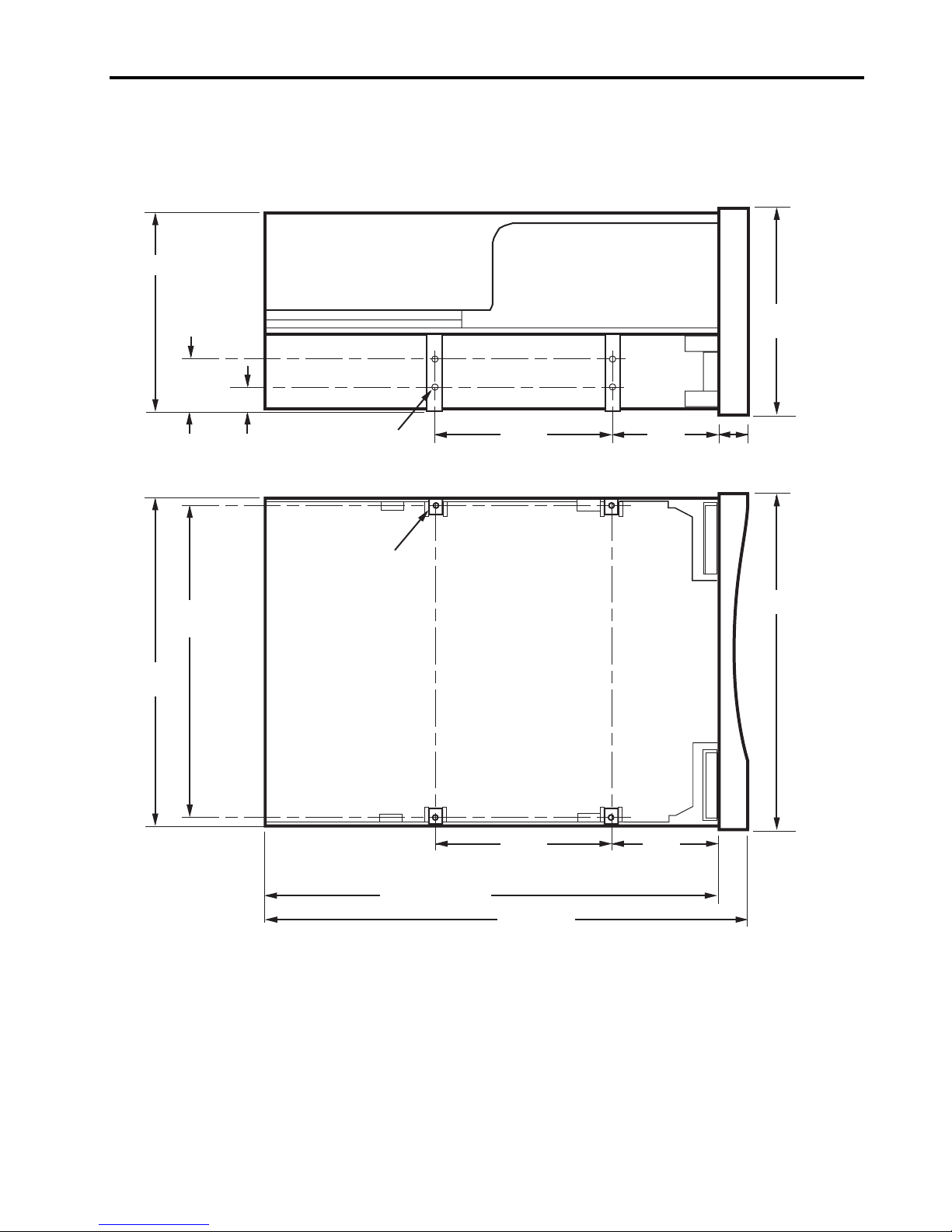
Figure 1 on the following page shows the dimensions of the internal Viper 200 drive.
Includes rubber feet (case alone is 6.45 inches high)
2
Includes fan grill on back of drive (case alone is 11.9 inches long)
Internal drive
without bezel
3.25 inches
(82.6 mm) max
5.75 inches
(146.05 ± 0.25 mm)
8.06 inches
(205 mm) max
6.2 lb. (2.82 kg) 6.5 lb. (2.95 kg) 9.5 lb (5.44 kg)
with bezel
3.32 inches
(84.26 mm)
5.82 inches
(147.75 mm)
8.346 inches
(212 mm)
External
drive
6.75 inches
(171.4 mm)
7.5 inches
(190.5 mm)
12 inches
(304.8 mm)
1
2
Installation
Figure 1. Internal Viper Drive—dimensions
7
82.6 mm (max)
21.80
± 0.20 mm
139.70 mm
± 0.20 mm
146.05
± 0.25 mm
9.90
± 0.20 mm
M3 X 5.0
4X Near side
4X Far side
4X M3 X 5.0
79.24
± 0.20 mm
Bottom View
Side View
± 0.20 mm
84.26 mm
(max)
48.9
7 mm
147.75 mm
205 mm (max)
79.24
± 0.20 mm
212 mm
48.9
± 0.20 mm

8 Viper 200 LTO Product Manual
Power specifications
The external Viper 200 drives (STU62001LW and STU62001WD) come with a builtin 90-260VAC (47-63 Hz) automatic switching power supply.
Maximum voltage and power specifications for the internal Viper 200 drives
(STU42001LW and STU62001WD) are listed in the tables below.
Voltage and current
+12 VDC +5 VDC
DC Voltage Tolerance + or – 10% + or – 5 %
Non-operating max voltage 14 Volts peak 7 Volts peak
Max Operating current
Continuous:
Peak:
Standby current (max) 0.5 amps RMS 2.0 amps RMS*
1.0 amps RMS
3.0 amps (1 sec max)
3.5 amps max RMS*
NA
Ripple (peak-to-peak)
Power dissipation
Max Standby Power 14 watts RMS*
Max Continuous Operating Power 30 watts RMS*
Max Peak Operating Power 48.5 watts (1 sec max)
* RMS parameters measured at the power connector using a true RMS digital meter.
Power connector
The following table lists pin assignments of the power connector for the internal Viper
drive.
Pin Assignment
1 +12 VDC power
2 +12 VDC return
3 +5 VDC return
4 +5 VDC power
100 mV
≤
100 mV
≤
 Loading...