

Seagate STU62001LW-S,Viper STU42001LW,Viper STU42001WD,Viper STU42001FC,Viper STU62001LW,Viper STU62001WD Installation Manual

Viper 200®
LTO Ultrium Tape Drive
Installation Manual

© 2002 Seagate Removable Storage Solutions LLC All rights reserved
Manufacturing Part Number: 100248193
Seagate and the Seagate logo are trademarks of Seagate Technology LLC.
Viper is a trademark of Seagate Removable Storage Systems LLC. Other
product names are trademarks or registered trademarks of their owners.
Seagate reserves the right to change, without notice, product offerings or
specifications. No part of this publication may be reproduced in any form
without written permission from Seagate Removable Storage Solutions LLC.
Publication T003, Rev. C4 September 04, 2002

Viper 200
LTO Ultrium Tape Drive
Installation Manual


Viper 200 Installation Manual 3
Contents
Contents 3
FCC notice 4
Introduction 5
Unpacking and Inspection 6
Installing an internal HVD or LVD Viper 200 7
Before you begin 7
Configuring an internal HVD or LVD drive 8
Mounting an an internal HVD or LVD drive 10
Cables and connectors (internal HVD or LVD drive) 12
Installing an internal Fibre Channel Viper 200 15
Before you begin 15
Configuring an internal Fibre Channel drive 16
Mounting an internal Fibre Channel drive 18
Cables and connectors (internal Fibre Channel drive) 20
Installing an external Viper 200 23
Configuring an external drive 23
Connecting the SCSI interface cable 24
Connecting the power cord 24
Operating and maintaining the Viper 200 25
Front Panel Display 25
Using Ultrium Cartridges 27
Drive maintenance 30
Parking the drive for shipping 31
Emergency reset and emergency cartridge eject 32
Manual cartridge removal 33
Unix configuration settings 41
A word about SCSI controllers 41
Configuring for the DEC/Compaq Unix Environment 42
Configuring for the Sun Environment 44
Configuring for the IBM AIX Environment 47
Configuring for SCO Open Server 5.0.x 49
Configuring for Linux 51
Configuring for SGI Irix 53
Configuring for HP-UX 11.0 55
Technical support 57
World-wide services: 57
Regional services 57

4 Viper 200 Installation Manual
FCC notice
This equipment has been tested and found to comply with the
limits for a Class B digital device, pursuant to part 15 of the FCC
Rules. These limits are designed to provide reasonable protection
against harmful interference in a residential installation. This
equipment generates, uses and can radiate radio frequency energy
and, if not installed and used in accordance with the instructions,
may cause harmful interference to radio communications.
However, there is no guarantee that interference will not occur in a
particular installation. If this equipment does cause harmful
interference to radio or television reception, which can be
determined by turning the equipment off and on, the user is
encouraged to try to correct the interference by one or more of the
following measures:
• Reorient or relocate the receiving antenna.
• Increase the separation between the equipment and receiver.
• Connect the equipment into an outlet on a circuit different
from that to which the receiver is connected.
If necessary, you should consult the dealer or an experienced radio/television
technician for additional suggestions. You may find the booklet, How to
Identify and Resolve Radio-TV Interference Problems, prepared by the
Federal Communications Commission, helpful. This booklet (Stock No. 004000-00345-4) is available from the U.S. Government Printing Office,
Washington, DC 20402.
Warning. Changes or modifications made to this equipment, which have
not been expressly approved by Seagate, may cause radio
and television interference problems that could void the user’s
authority to operate the equipment.
Further, this equipment complies with the limits for a Class B digital
apparatus in accordance with Canadian Radio Interference Regulations
ICES-003.
Cet appareil numérique de la classe B est conforme a la norme NMB-003 du
Canada.
The external device drive described in this manual requires shielded
interface cables to comply with FCC emission limits.
Additional Warnings:
• To prevent fire or electrical shock hazard, do not expose the unit to rain
or moisture.
• To avoid electrical shock, do not open the cabinet.
• Refer servicing to qualified personnel.

Viper 200 Installation Manual 5
Introduction
This installation manual summarizes the installation and
operation of the Seagate
®
Viper 200® Ultrium tape drive. The
Viper 200 is a high-performance eight-channel Ultrium tape
drive that uses ½-inch Ultrium tape cartridges with a native
capacity of up to 100 Gbytes (200 Gbytes assuming 2:1 data
compression). It supports Read While Write (RWW) and
provides intelligent hardware data compression as well as
cartridge soft load. It comes with an ULTRA 2 WIDE SCSI
LVD (LVD), an Ultra Wide SCSI HVD (HVD) or a Fibre
Channel LC Optical (FC) interface and a library RS-422 serial
interface.
The Viper 200 design is well suited for mid-range to high-end
servers, mainframe systems, and tape library automation
systems.
The internal Viper 200 is designed to fit in a 5¼-inch fullheight drive bay. The external drive is a standalone unit with
built-in power supply. The following Viper 200 models are
covered in this manual:
Model number Form factor Interface
STU42001LW 5.25-inch Internal drive LVD
STU42001WD 5.25-inch Internal drive HVD
STU42001FC 5.25-inch Internal drive FC
STU62001LW External drive LVD
STU62001WD External drive HVD
Note: LVD drives should be installed only in an SCSI LVD
environment, HVD drives should be only be used in a
SCSI HVD environment, and FC drives should only be
installed in an Fibre Channel environment.

6 Viper 200 Installation Manual
Unpacking and Inspection
Although drives are inspected and carefully packaged at the
factory, damage may occur during shipping. Follow these
steps for unpacking the drive.
1. Visually inspect the shipping containers and notify your
carrier immediately of any damage.
2. Place shipping containers on a flat, clean, stable surface;
then carefully remove and verify the contents against the
packing list. If parts are missing or the equipment is
damaged, notify your Seagate representative.
3. Save the containers and packing materials in case you
ever have to reship the drive.
Viper 200 Installation Manual 7
Installing an internal HVD or LVD Viper 200
This section describes the steps necessary to install an
internal Viper 200 drive with an Ultra 2 Wide SCSI LVD or
Ultra Wide SCSI HVD interface. For instructions on installing
a Fibre Channel drive, see page 15. For instructions on
installing an external HVD or LVD drive, see page 23.
Before you begin
The following guidelines and cautions apply to handling and
installing internal tape drives. Keep them in mind as you
install the drive.
• Determine if the drive is an FC, HVD or an LVD model.
Install an HVD drive only in an HVD environment, and an
LVD model only in an LVD environment. Do not mix HVD
and LVD devices. Look at the label above the drive’s
connector to determine if the drive is an FC, HVD or an
LVD model:
LVD label:
HVD label:
FC label:
Fibre Channel
Caution. Plugging an HVD drive into an LVD bus or vice
versa will make the entire bus non-functional and
may permanently damage the drive or other
SCSI devices on the bus.
• Because the Viper 200 drive can transmit data at up to 80
Mbytes/second, it is recommended that a maximum of
two Vipers be connected to one SCSI host adapter.
• Internal drives contain some exposed components that
are sensitive to static electricity. To reduce the possibility
of damage from static discharge, the drives are shipped
in a protective antistatic bag. Do not remove the drive
from the antistatic bag until you are ready to install it.
• Before you remove the drive from the antistatic bag,
touch a metal or grounded surface to discharge any static
electricity buildup from your body.

8 Viper 200 Installation Manual
• Always lay the drive either on top of the antistatic bag or
place it inside of the bag to reduce the chance of damage
from static discharge.
Configuring an internal HVD or LVD drive
Before you install the tape drive in your computer, you may
need to configure the drive’s SCSI ID and other drive
features. Jumpers located on the back of the drive (near the
left edge of the drive) are used to configure the SCSI ID and
to enable termination power.
Default settings
The default drive settings for the Viper 200 are listed below:
• SCSI ID: 6
• Termination Power: disabled.
If these default settings are appropriate for your needs, skip
ahead to “Mounting an internal HVD or LVD drive” on page
10.
Jumper settings
Configuration jumpers on the back of the drive control the
drive’s SCSI ID and SCSI terminator power. The jumpers can
also be used for remote SCSI address selection. Figure 1 on
the following page shows the locations of the jumper blocks
for the internal Viper 200.
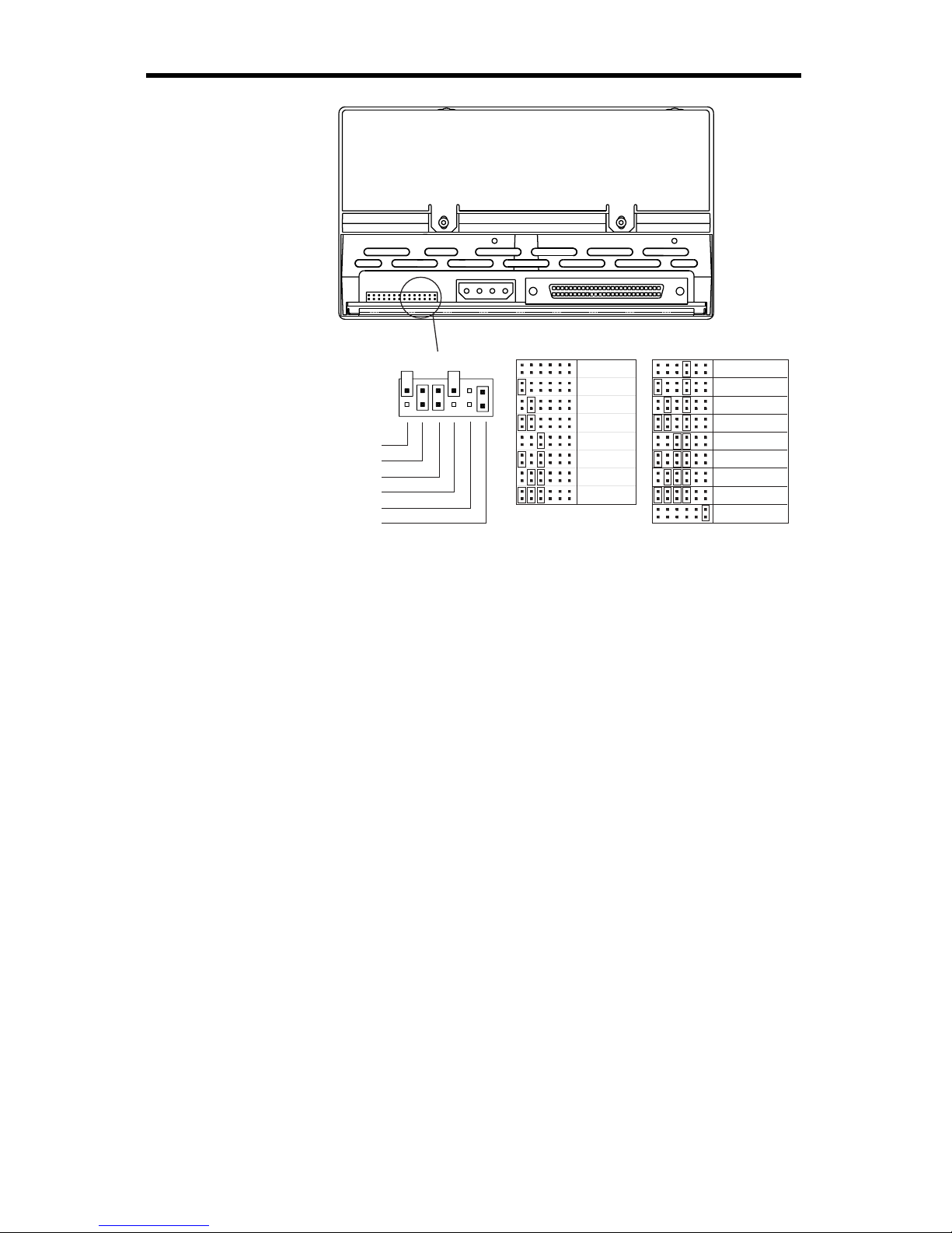
Viper 200 Installation Manual 9
Drive-configuration jumper pins
Jumper Settings:
Default
settings:
SCSI ID=0
SCSI ID=1
SCSI ID=2
SCSI ID=3
SCSI ID=4
SCSI ID=5
SCSI ID=6
SCSI ID=7
SCSI ID=8
SCSI ID=9
SCSI ID=10
SCSI ID=11
SCSI ID=12
SCSI ID=13
SCSI ID=14
SCSI ID=15
Term. power
Pins: Function:
1-2 SCSI ID bit 0
3-4 SCSI ID bit 1
5-6 SCSI ID bit 2
7-8 SCSI ID bit 3
9-10 Reserved
11-12 Termination Power
Figure 1. Jumper settings for the internal Viper 200 with
LVD or HVD interface
SCSI Address Selection (pins 1 through 8)
You can select the SCSI address used by the drive by
placing the appropriate jumpers on pin-pairs 1-2 through
7-8, as shown in Figure 1.
Note: Each SCSI device on a bus must have a unique SCSI
ID. The SCSI controller or host adapter generally uses
ID 7. In some systems, the boot drive uses ID 0 or ID 1.
Terminator power (pins 11 and 12)
Internal HVD and LVD Viper 200 drives are shipped with
terminator power disabled, as shown in Figure 1. You can
enable terminator power, if necessary, by placing a jumper
across pins 11 and 12.
Note: The internal Viper 200 does not provide SCSI
termination. Thus, a terminator must be installed on
the drive if it is the last device in a SCSI chain. See
“SCSI termination” on page 13 for more information.

10 Viper 200 Installation Manual
Mounting an internal HVD or LVD drive
You can mount the internal Viper 200 either horizontally or
vertically with the drives left side facing up (see Figure 2). If a
drive is mounted vertically, the left side of the drive must face
up and the side of the drive should be within 5 degrees of
horizontal. If a drive is mounted horizontally, the base of the
drive must be within 15 degrees of horizontal and the PCB
side of the drive must face down.
YES YES NO NO
Figure 2. Acceptable mounting orientations for the
internal Viper 200
Mount the drive in a 5.25-inch, full-height drive bay and
secure it using two M3.0 metric screws on each side of the
drive. The locations of screw holes are shown in Figure 3 on
the following page. Do not use screws longer than 5 mm or
you may damage the drive.
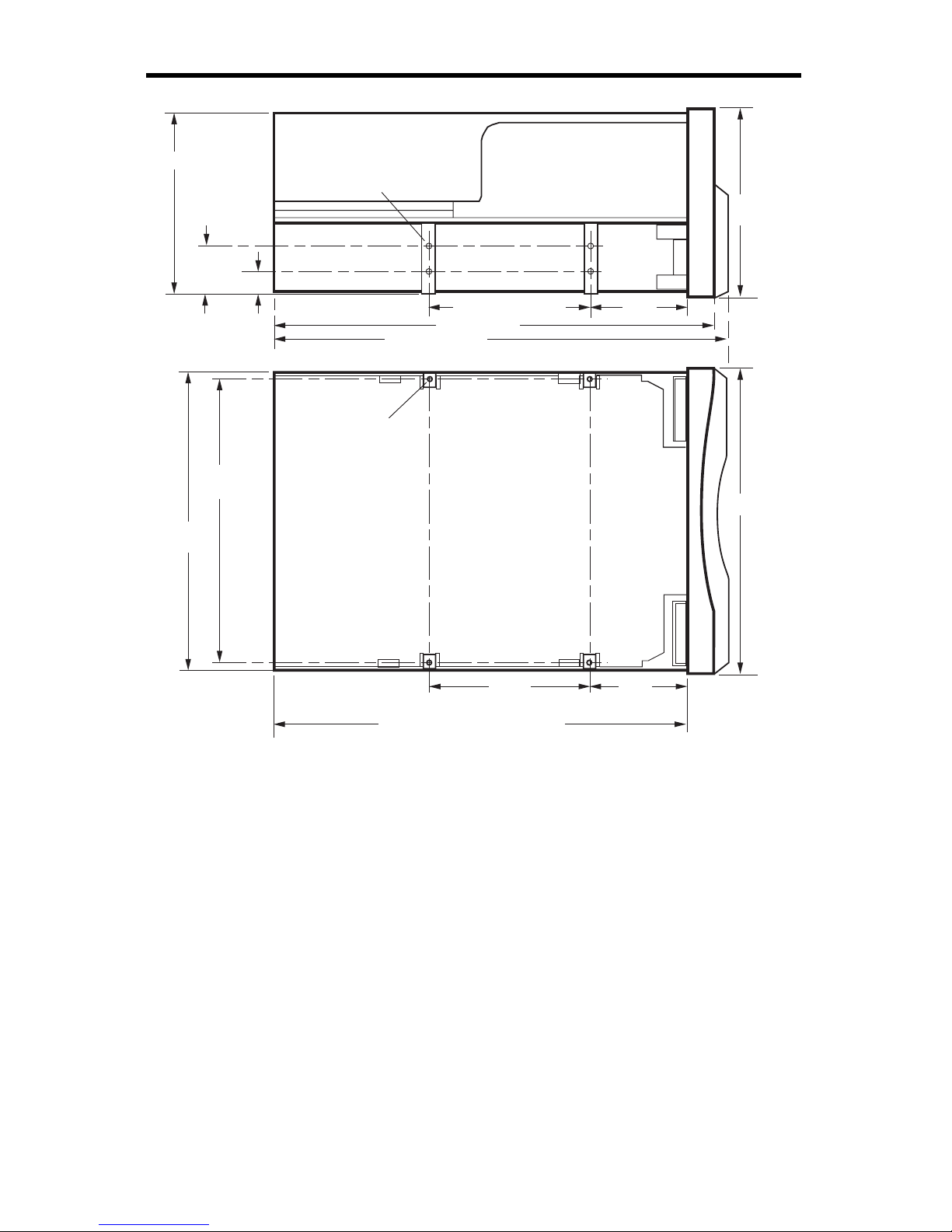
Viper 200 Installation Manual 11
9.90
± 0.20 mm
21.80
± 0.20 mm
M3 X 5.0
4X Near side
4X Far side
82.6 mm (max)
Side View
Bottom View
4X M3 X 5.0
146.05
± 0.25 mm
139.70 mm
± 0.20 mm
79.24 ± 0.20 mm
79.24
± 0.20 mm
48.9
± 0.20 mm
48.9
± 0.20 mm
84.26 mm
(max)
147.75 mm
205 mm (max, without bezel)
210.41 mm
219.00 mm max
Figure 3. Viper 200 mounting dimensions
12 Viper 200 Installation Manual
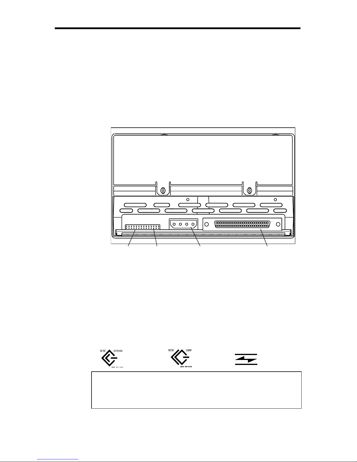
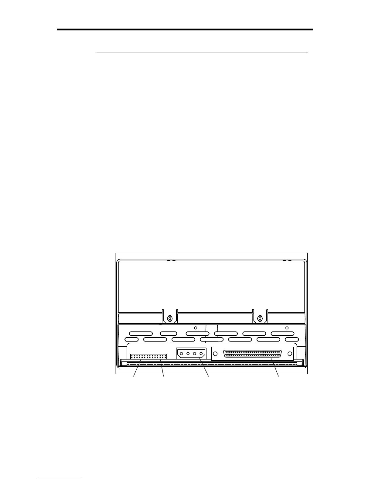
Cables and connectors (internal HVD or LVD drive)
Connecting the SCSI interface cable
Viper 200 drives are designed to be used with an Ultra2 SCSI
interface with a 68-pin HVD or LVD SCSI connector. Before
attaching or detaching cables, turn off all power to the drive
and computer. Attach the interface cable to the 68-pin SCSI
interface connector on the back of the drive (see Figure 4).
Serial Interface
connector (pins
on 2-mm centers)
Driveconfiguration
jumper pins
5 / 12 Volt
power
connector
68-pin
SCSI
connector
Figure 4. Rear view of the Viper 200 internal drive
Install an HVD drive only in an HVD environment and an LVD
drive only in an LVD environment. Do not mix HVD and LVD
devices. Look at the label above the drive’s SCSI connector
to determine if the drive is an HVD or an LVD model:
LVD label:
HVD label:
FC label:
Fibre Channel
Caution. Plugging an HVD drive into an LVD bus or vice
versa will make the entire bus non-functional and
may permanently damage the drive or other
SCSI devices on the bus.
Viper 200 Installation Manual 13
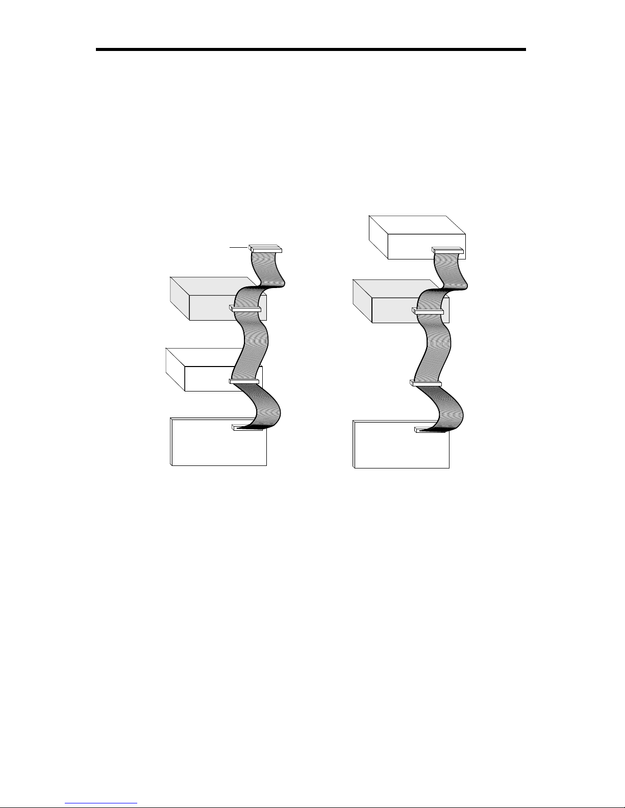
SCSI Termination
The Viper 200 internal drive does not provide SCSI
termination. You must place a SCSI bus terminator or a SCSI
device with termination enabled at the end of a SCSI chain.
Two examples of SCSI termination are shown in Figure 5.
The Viper 200 does provide terminator power if a jumper is
placed on the termination power jumper, as shown in Figure
1 on page 10.
SCSI Controller
(termination enabled)
Tape drive
SCSI device
SCSI device
(termination
enabled)
(termination
disabled)
(no
termination)
SCSI Terminator
SCSI Controller
(termination enabled)
Tape drive
(no
termination)
Figure 5. Two possible SCSI termination examples for
internal Viper 200.
Connecting a Serial Interface Cable (for tape libraries)
The Viper 200 drive includes an RS-422 serial interface for
tape libraries. The RS-422 serial interface connector is on the
lower left side of the back of the drive, as shown in Figure 4
on the previous page. The pin descriptions for the Serial
Interface connector are shown in the table on the following
page. These pins are on 2-mm centers.
14 Viper 200 Installation Manual
Pin numbers Description
1 through 8 Reserved (do not use)
9 Lib RXD-P (input to drive)
10 GND
11 Lib RXD-N (input to drive)
12 GND
13 Lib TXD-P (output from drive)
14 GND
15 Lib TXD-N (output from drive)
16 GND
Connecting a Power Cable
Attach a four-pin 5-volt / 12-volt power cable to the power
connector on the back of the drive. Figure 6 shows the
location of the power connector.
The recommended 4-pin power connector for the internal
Viper 200 is an AMP 1-48024-0 housing with AMP 60617-1
pins or equivalent.
Serial Interface
connector (pins
on 2-mm centers)
Driveconfiguration
jumper pins
5 / 12 Volt
power
connector
68-pin
SCSI
connector
Figure 6. Rear view of the Viper 200 internal drive,
showing 4-pin power connector

Viper 200 Installation Manual 15
Installing an internal Fibre Channel Viper 200
This section describes the steps necessary to install an
internal Viper 200 with a Fibre Channel LC Optical (FC)
interface. For instructions on installing a drive with an Ultra 2
Wide SCSI LVD or Ultra Wide SCSI HVD interface, see page
7. For instructions on installing an external HVD or LVD drive,
see page 23.
Before you begin
The following guidelines and cautions apply to handling and
installing internal tape drives. Keep them in mind as you
install the drive.
• Make sure your drive is an FC model. Install an FC model
only in a Fibre Channel environment. Look at the label
above the drive’s connector to determine if the drive is an
FC, HVD or an LVD model:
LVD label:
HVD label:
FC label:
Fibre Channel
• The Viper 200 drive can transmit data at an
instantaneous rate of 106.25 Mbytes/second and a
sustained rate of 80 Mbytes/second. In a Fibre Channel
loop environment, the maximum number of drives that
can be used simultaneously depends on the bandwidth of
the loop.
• Internal drives contain some exposed components that
are sensitive to static electricity. To reduce the possibility
of damage from static discharge, the drives are shipped
in a protective antistatic bag. Do not remove the drive
from the antistatic bag until you are ready to install it.
• Before you remove the drive from the antistatic bag,
touch a metal or grounded surface to discharge any static
electricity buildup from your body.
16 Viper 200 Installation Manual
• Always lay the drive either on top of the antistatic bag or
place it inside of the bag to reduce the chance of damage
from static discharge.
Configuring an internal Fibre Channel drive
Before you install the tape drive in your computer, you may
need to configure the drive’s hard-assigned loop identifier
and other drive features. Jumpers located on the back of the
drive (see Figure 7) are used to configure the ID.
BA
4-pin power
connector
Assigned loop identifier
jumper pins
serial
interface
connector
fibre-channel
optical connectors
Figure 7. Connectors and jumpers on the back of the
Viper 200 Fibre Channel drive
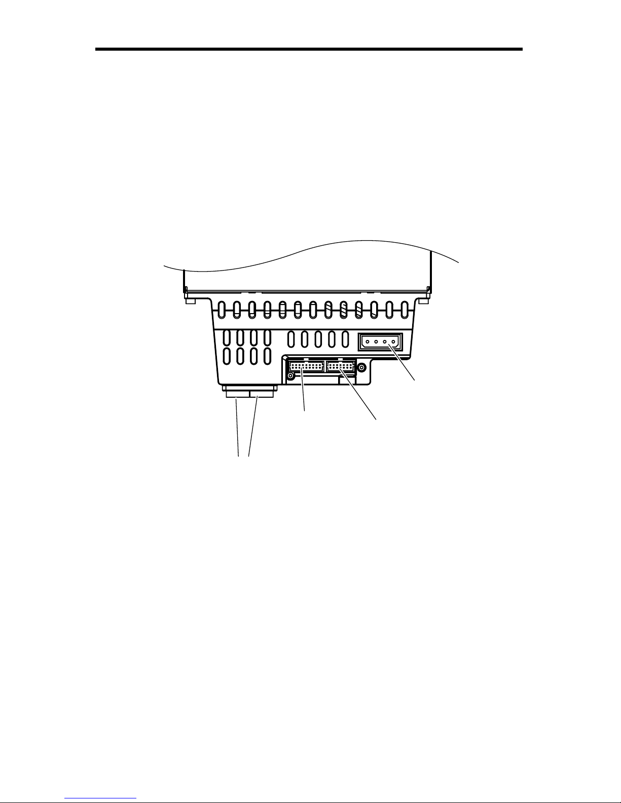
Jumper settings
Configuration jumpers on the back of the drive control the
assigned loop identifier, which the drive will attempt to
acquire during the LIHA (hard address) phase of the Loop
Initialization Process (LIP). The jumpers can also be used for
remote ID selection. Figure 8 shows the location of the
assigned loop identifier jumper pins on the Viper 200 FC
drive.
Viper 200 Installation Manual 17
BA
Assigned loop identifier
jumper pins
Pin
Numbers
13 11 9 7 5 3 1
14 12 10 8 6 4 2
Figure 8. Assigned loop identifier jumper pins for the
internal FC Viper 200
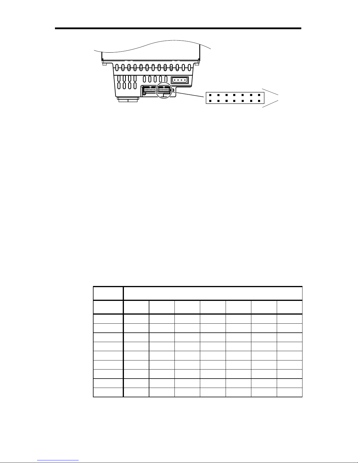
You can select the hard ID used by the drive by placing
jumpers on the appropriate assigned loop identifier jumper
pins. The seven sets of jumpers represent seven binary
digits, with the lowest binary weight (2^0) on the left (pins 13-
14) and the highest binary weight (2^6) on the right (pins 1-
2). If a jumper is placed on a set of pins (ON), the bit is set as
a “1.” If no jumper is on a set of pins, the bit is set as “0.”
The assigned loop identifier can be set from 0 to 125 (7Eh).
The Viper 200 FC is shipped with no jumpers in place (an ID
of 0000000).
The table below illustrates the system used for ID selection.
“ON” indicates a jumper installed on the pins indicated. Blank
cells indicate pins without a jumper installed.
Jumper Pins (blank indicates no jumper)
Loop ID 13-14 11-12 9-10 7-8 5-6 3-4 1-2
0
1
ON
2
ON
3
ON ON
4
ON
5
ON ON
6
ON ON
….
125
ON ON ON ON ON ON
Note: Setting an invalid ID (7Fh or 7Eh) will cause the drive
not to participate in LIHA and to instead attempt to
acquire an address during the LISA (soft address)
phase of LIP.
 Loading...