

Seagate ST9655 Family,ST9655AG,ST9550AG,ST9385AG Installation Manual

. . . . . . . . . . . . . . . . . . . . . . . . . .
ST9655 Family
. . . . . . . . . . . . . . . . . . . . . . . . . .
ST9655AG, ST9550AG
. . . . . . . . . . . . . . . . . . . . . . . . . .
ST9385AG
. . . . . . . . . . . . . . . . . . . . . . . . . .
AT Interface Drives
. . . . . . . . . . . . . . . . . . . . . . . . . .
Installation Guide
. . . . . . . . . . . . . . . . . . . . . . . . . .

Contents
Read before you begin
Configuring the drive . . . . . . . . . . . . . . . . . . . . 2
Attaching cables . . . . . . . . . . . . . . . . . . . . . . . 2
Mounting the drive . . . . . . . . . . . . . . . . . . . . . 4
Configuring your computer . . . . . . . . . . . . . . . . . 6
Formatting and partitioning the drive . . . . . . . . . . . 9
Installation troubleshooting . . . . . . . . . . . . . . . 10
Compatibility notes . . . . . . . . . . . . . . . . . . . . 17
Technical support services . . . . . . . . . . . . . . . . 18
Storing and shipping your drive . . . . . . . . . . . . . 20
© 1994 Seagate Technology, Inc. All rights reserved
Publication Number: 36286-001, Rev. A
October 1994
Seagate, Seagate Technology and the Seagate logo are registered trademarks of Seagate Technology, Inc. SeaFAX, SeaFONE, SeaBOARD and SeaTDD are trademarks of Seagate
Technology, Inc. Other product names are registered trademarks
or trademarks of their owners.
Seagate reserves the right to change, without notice, product
offerings or specifications. No part of this publication may be
reproduced in any form without written permission from Seagate
Technology, Inc.
... . . . . . . . . . . . . . . . . . . 1

ST9655 Family Installation Guide, Rev. A 1
Read before you begin
Application. Your drive is designed for IBM AT and compatible
personal computers, particularly laptop and notebook models.
Warning. Turn off the computer (and, if you have a notebook
or laptop computer, remove the battery) before you
open the case or touch any internal components.
Caution. Special training or tools may be needed to service
laptop and notebook computers. Opening the case
may void your warranty. Review the terms and conditions of your warranty before opening the case.
Static discharge. Observe the following precautions:
• Before handling any components, put on a grounded wrist strap.
• Use antistatic padding on all work surfaces.
• Avoid static-inducing carpeted areas.
• Keep the drive in its static-shielded bag until you are ready to
complete the installation. Do not attach any cables to the drive
while it is in its static-shielded bag.
• Handle the drive by its edges or frame.
• Do not touch the I/O connector pins or the circuit board.
Drive handling. The drive is extremely fragile—handle it with
care. Do not attach labels to any part of the drive.
Inspection. After you are familiar with the handling precautions
listed above, inspect the drive. If it appears to be damaged, call
your distributor or dealer immediately.
Warranty. See your authorized Seagate
Maintenance and repair. Seagate drives do not require main-
tenance. The head/disc assembly is sealed; if you break the seal,
...
®
distributor or dealer.

2 ST9655 Family Installation Guide, Rev. A
you void the warranty. Seagate customer service centers are the
only facilities authorized to repair Seagate drives. Seagate does
not sanction any third-party repair facilities.
Configuring the drive
1. Put on a grounded wrist strap. Wear the grounded wrist
strap throughout the installation procedure.
2. Install master/slave jumpers. In a two-drive system, you
need to designate one drive as the master, or drive 0, and
the other drive as the slave, or drive 1. To do this, install the
master/slave jumpers as shown in Figure 1. In a one-drive
system, configure the drive as a master (no jumpers installed).
Alternatively, you can configure the drive as a master or
slave using the cable select option. To use this option, the
host system and both drives must support cable select.
Cable selection requires a special daisy-chain cable that
grounds pin 28 (CSEL) on one of its two drive connectors.
If you attach the drive to the grounded CSEL connector, it
becomes a master. If you attach the drive to the ungrounded CSEL connector, it becomes a slave.
To configure an ST9655 family drive for cable select, install
both master/slave jumpers, as shown in Figure 1.
Attaching cables
This drive is designed for a host computer that supplies
interface signals and +5V power through a single 44-pin
connector and cable. If your computer has a fixed connector
that attaches directly to the drive, skip ahead to the following
section, “Mounting the drive.” Otherwise, perform the steps
listed on page 4.
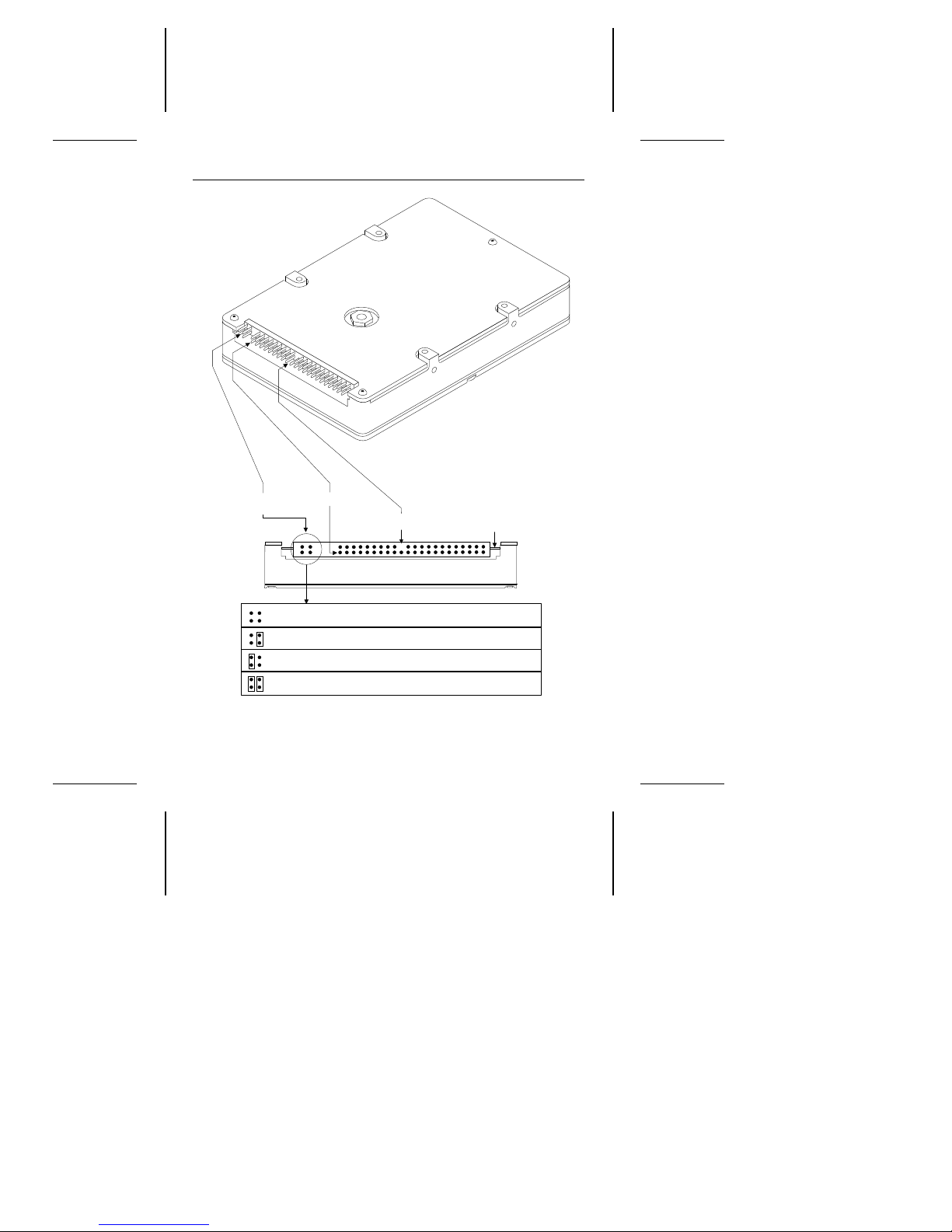
Master/slave
configuration jumpers
Circuit board
Pin 1
Pin 20 removed for keying
Note. Drive is shown with
circuit board up.
B D
A C
Drive is master; slave may be detected using DASP– signal
Drive is master; Seagate slave drive present
Drive is slave; Seagate master drive present
Use CSEL pin grounding to differentiate master from slave
ST9655 Family Installation Guide, Rev. A 3
Figure 1. ATA interface connector and master/slave
configuration jumpers

4 ST9655 Family Installation Guide, Rev. A
1. Turn off the computer and remove the battery.
2. Put on a grounded wrist strap.
3. Open your computer case. See your system manual for
instructions.
Caution. Opening the case may void your computer’s warranty.
4. Connect the 44-pin interface/power cable. Match pin 1 of
the cable to pin 1 of the interface connectors on the drive and
on the computer. Pin 1 is usually denoted by a stripe along
one edge of the cable. The location of pin 1 on the drive
interface connector is shown in Figure 1 on page 3. The cable
should be no longer than 18 inches (0.457 meters).
Caution. The printed circuit cables used in some laptop com-
puters are delicate. Be careful not to tear them.
Mounting the drive
Mount the drive securely in the computer using M3X0.5 metric
screws in the four bottom mounting holes or the four side mounting
holes shown in Figure 2. You can mount the drive in any orientation.
Be careful not to strain or crimp the interface/power cable.
Caution. To prevent damage to the drive:
• Be careful not to bend the drive connector pins, especially
when plugging the drive into a fixed connector.
• Use mounting screws of the correct size and length.
• Gently tighten the mounting screws—do not apply more than
3 inch-pounds of torque.
• Do not insert mounting screws more than 0.15 inch.
Note. This drive meets industry-standard MCC mounting speci-
fications. When installing this drive in a fixed-mounting
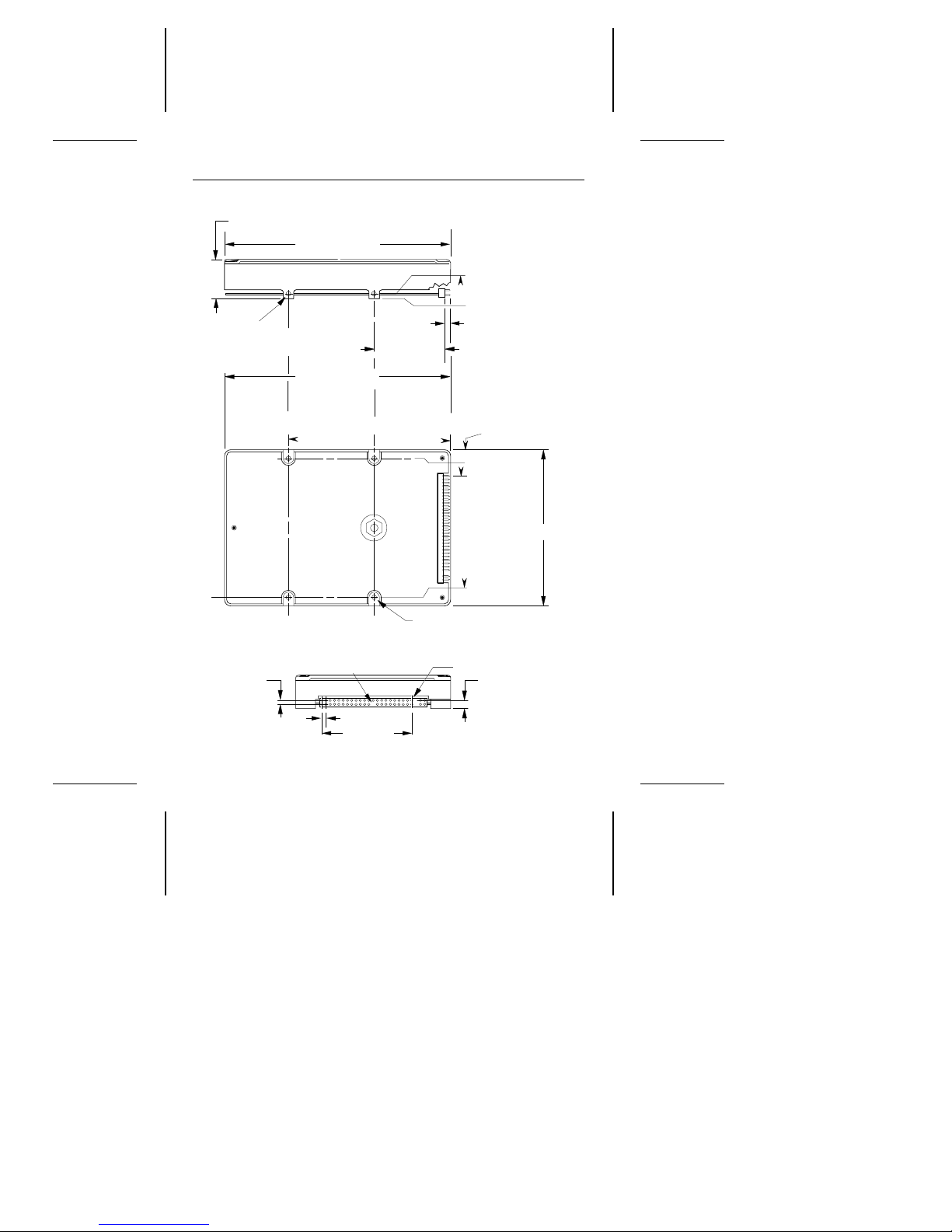
0.747 ± 0.007 (18.97 ± 0.18)
4X 3 mm × 0.5 mm
× 0.15 in. (3.81 mm) deep
min. full thread
(2 each side)
1.375 ± 0.015
(34.93 ± 0.38)
0.118 ± 0.010
(3.00 ± 0.25)
4.020 (102.11) max
(head/disc assembly
to tip of pins)
1.500 ± 0.010
(38.10 ± 0.25)
0.000
1.227 ± 0.020
(31.17 ± 0.51)
0.155 ± 0.020
(3.94 ± 0.51)
0.239 ± 0.035
(6.07 ± 0.89)
0.000
0.000
2.760 (70.10) max
2.430 ± 0.010
(61.72 ± 0.25)
0.157 ± 0.015
(3.99 ± 0.38)
Pin 1
0.079 (2.00)
Pin 20 removed
for keying
0.152 ± 0.005
(3.86 ± 0.13)
0.079 (2.00)
1.659 (42.14)
Dimensions are in inches (mm)
4X 3 mm × 0.5 mm
× 0.15 in. (3.81 mm) deep
min. full thread
4.010 (101.85) max.
(head/disc assembly)
ST9655 Family Installation Guide, Rev. A 5
Figure 2. Mounting dimensions for the ST9655 family drives

6 ST9655 Family Installation Guide, Rev. A
application, you must use MCC-compatible connectors
and mounting hardware. If the mounting holes in your
computer do not line up with the mounting holes on the
drive, your computer may not be MCC-compatible.
Configuring your computer
Before your computer can recognize a new drive, you must enter
basic information about the drive into the computer’s long-term
memory (usually a battery-powered CMOS chip). The computer’s basic input/output system (BIOS) uses this information to
control the flow of data to and from the drive.
Note. Some newer computers can automatically determine your
drive type and configure themselves appropriately at startup.
Read your system manual to determine whether this applies
to your computer. If so, then skip ahead to “Formatting and
partitioning the drive,” on page 9.
If your computer cannot automatically determine your drive type,
you must run a system setup program to specify the number of
cylinders, heads and sectors for each drive in your system. This
procedure is described on the following page. The table below
lists cylinder, head and sector information for the ST9655 family
drives.
Drive specification ST9655AG ST9550AG ST9385AG
No. cylinders 1,016 942 934
No. read/write heads 16 16 14
No. sectors per track 63 59 51
Total no. sectors 1,024,128 889,248 666,876
Bytes per sector 512 512 512
Capacity (Mbytes)
BIOS calculated 499 434 325
Usable 524 455 341
 Loading...