

Seagate ST8000VX004 User Manual
SATA Product Manual
Standard 512E model
ST8000VX004
100844776, Rev. B
Gen 2 - May 2019

Document Revision History
Revision Date Pages affected and Description of changes
Rev. A 04/30/2019 Initial release.
Rev. B 05/09/2019
fc, 5-7, 22 & 27: Removed 6TB model and specs
8: Updated Table 2 DC power requirements Operating &* footnote
© 2019 Seagate Technology LLC. All rights reserved.
Publication number: 100844776, Rev. B May 2019
Seagate, Seagate Technology and the Spiral logo are registered trademarks of Seagate Technology LLC in the United States and/or other countries. SkyHawk, PowerChoice and SeaTools
are either trademarks or registered trademarks of Seagate Technology LLC or one of its affiliated companies in the United States and/or other countries. The FIPS logo is a certification
mark of NIST, which does not imply product endorsement by NIST, the U.S., or Canadian governments. All other trademarks or registered trademarks are the property of their respective
owners.
No part of this publication may be reproduced in any form without written permission of Seagate Technology LLC.
Call 877-PUB-TEK1 (877-782-8351) to request permission.
When referring to drive capacity, one gigabyte, or GB, equals one billion bytes and one terabyte, or TB, equals one trillion bytes. Your computer’s operating system may use a different
standard of measurement and report a lower capacity. In addition, some of the listed capacity is used for formatting and other functions, and thus will not be available for data storage.
Actual quantities will vary based on various factors, including file size, file format, features and application software. Actual data rates may vary depending on operating environment
and other factors. The export or re-export of hardware or software containing encryption may be regulated by the U.S. Department of Commerce, Bureau of Industry and Security (for

Contents
Seagate® Technology Support Services . . . . . . . . . . . . . . . . . . . . . . . . . . . . . . . . . . . . . . . . . . . . . . . . . . . . . . . . . . . . . . . 4
1.0 Introduction . . . . . . . . . . . . . . . . . . . . . . . . . . . . . . . . . . . . . . . . . . . . . . . . . . . . . . . . . . . . . . . . . . . . . . . . . . . . . . . . . 5
1.1 About the Serial ATA interface . . . . . . . . . . . . . . . . . . . . . . . . . . . . . . . . . . . . . . . . . . . . . . . . . . . . . . . . . . . . . . . . 5
2.0 Drive specifications . . . . . . . . . . . . . . . . . . . . . . . . . . . . . . . . . . . . . . . . . . . . . . . . . . . . . . . . . . . . . . . . . . . . . . . . . . 6
2.1 Specification summary tables . . . . . . . . . . . . . . . . . . . . . . . . . . . . . . . . . . . . . . . . . . . . . . . . . . . . . . . . . . . . . . . . . 6
2.2 Formatted capacity . . . . . . . . . . . . . . . . . . . . . . . . . . . . . . . . . . . . . . . . . . . . . . . . . . . . . . . . . . . . . . . . . . . . . . . . . . 7
2.2.1 LBA mode. . . . . . . . . . . . . . . . . . . . . . . . . . . . . . . . . . . . . . . . . . . . . . . . . . . . . . . . . . . . . . . . . . . . . . . . . . 7
2.3 Recording and interface technology . . . . . . . . . . . . . . . . . . . . . . . . . . . . . . . . . . . . . . . . . . . . . . . . . . . . . . . . . . 8
2.4 Start/stop times . . . . . . . . . . . . . . . . . . . . . . . . . . . . . . . . . . . . . . . . . . . . . . . . . . . . . . . . . . . . . . . . . . . . . . . . . . . . . . 8
2.5 Power specifications . . . . . . . . . . . . . . . . . . . . . . . . . . . . . . . . . . . . . . . . . . . . . . . . . . . . . . . . . . . . . . . . . . . . . . . . . . 8
2.5.1 Power consumption . . . . . . . . . . . . . . . . . . . . . . . . . . . . . . . . . . . . . . . . . . . . . . . . . . . . . . . . . . . . . . . . 8
2.5.2 Conducted noise . . . . . . . . . . . . . . . . . . . . . . . . . . . . . . . . . . . . . . . . . . . . . . . . . . . . . . . . . . . . . . . . . . . 9
2.5.3 Voltage tolerance . . . . . . . . . . . . . . . . . . . . . . . . . . . . . . . . . . . . . . . . . . . . . . . . . . . . . . . . . . . . . . . . . . 9
2.5.4 Extended Power Conditions - PowerChoice™ . . . . . . . . . . . . . . . . . . . . . . . . . . . . . . . . . . . . . . . 10
2.6 Environmental limits. . . . . . . . . . . . . . . . . . . . . . . . . . . . . . . . . . . . . . . . . . . . . . . . . . . . . . . . . . . . . . . . . . . . . . . . . 12
2.6.1 Humidity. . . . . . . . . . . . . . . . . . . . . . . . . . . . . . . . . . . . . . . . . . . . . . . . . . . . . . . . . . . . . . . . . . . . . . . . . . 12
2.6.2 Effective Altitude (sea level) . . . . . . . . . . . . . . . . . . . . . . . . . . . . . . . . . . . . . . . . . . . . . . . . . . . . . . . 12
2.7 Shock and Vibration . . . . . . . . . . . . . . . . . . . . . . . . . . . . . . . . . . . . . . . . . . . . . . . . . . . . . . . . . . . . . . . . . . . . . . . . . 13
2.7.1 Shock . . . . . . . . . . . . . . . . . . . . . . . . . . . . . . . . . . . . . . . . . . . . . . . . . . . . . . . . . . . . . . . . . . . . . . . . . . . . . 13
2.7.2 Vibration . . . . . . . . . . . . . . . . . . . . . . . . . . . . . . . . . . . . . . . . . . . . . . . . . . . . . . . . . . . . . . . . . . . . . . . . . . 13
2.8 Acoustics . . . . . . . . . . . . . . . . . . . . . . . . . . . . . . . . . . . . . . . . . . . . . . . . . . . . . . . . . . . . . . . . . . . . . . . . . . . . . . . . . . . . 14
2.9 Test for Prominent Discrete Tones (PDTs). . . . . . . . . . . . . . . . . . . . . . . . . . . . . . . . . . . . . . . . . . . . . . . . . . . . . 14
2.10 Electromagnetic immunity . . . . . . . . . . . . . . . . . . . . . . . . . . . . . . . . . . . . . . . . . . . . . . . . . . . . . . . . . . . . . . . . . . . 14
2.11 Reliability . . . . . . . . . . . . . . . . . . . . . . . . . . . . . . . . . . . . . . . . . . . . . . . . . . . . . . . . . . . . . . . . . . . . . . . . . . . . . . . . . . . 15
2.11.1 Annualized Failure Rate (AFR) and Mean Time Between Failures (MTBF) . . . . . . . . . . . . . 15
2.12 Agency and Safety Certifications . . . . . . . . . . . . . . . . . . . . . . . . . . . . . . . . . . . . . . . . . . . . . . . . . . . . . . . . . . . . . 16
2.12.1 Safety certification . . . . . . . . . . . . . . . . . . . . . . . . . . . . . . . . . . . . . . . . . . . . . . . . . . . . . . . . . . . . . . . . 16
2.12.2 Regulatory Models . . . . . . . . . . . . . . . . . . . . . . . . . . . . . . . . . . . . . . . . . . . . . . . . . . . . . . . . . . . . . . . . 16
2.12.3 European Union (EU) CE Marking Requirements . . . . . . . . . . . . . . . . . . . . . . . . . . . . . . . . . . . . 16
2.12.4 Australian RCM Compliance Mark . . . . . . . . . . . . . . . . . . . . . . . . . . . . . . . . . . . . . . . . . . . . . . . . . . 16
2.12.5 Canada ICES-003 . . . . . . . . . . . . . . . . . . . . . . . . . . . . . . . . . . . . . . . . . . . . . . . . . . . . . . . . . . . . . . . . . . 16
2.12.6 South Korean KC Certification Mark . . . . . . . . . . . . . . . . . . . . . . . . . . . . . . . . . . . . . . . . . . . . . . . . 16
2.12.7 Morocco Commodity Mark . . . . . . . . . . . . . . . . . . . . . . . . . . . . . . . . . . . . . . . . . . . . . . . . . . . . . . . . 17
2.12.8 Taiwanese BSMI . . . . . . . . . . . . . . . . . . . . . . . . . . . . . . . . . . . . . . . . . . . . . . . . . . . . . . . . . . . . . . . . . . . 17
2.12.9 FCC verification . . . . . . . . . . . . . . . . . . . . . . . . . . . . . . . . . . . . . . . . . . . . . . . . . . . . . . . . . . . . . . . . . . . 17
2.13 Environmental protection. . . . . . . . . . . . . . . . . . . . . . . . . . . . . . . . . . . . . . . . . . . . . . . . . . . . . . . . . . . . . . . . . . . . 18
2.13.1 European Union Restriction of Hazardous Substance Law. . . . . . . . . . . . . . . . . . . . . . . . . . . 18
2.13.2 China Requirements —China RoHS 2 . . . . . . . . . . . . . . . . . . . . . . . . . . . . . . . . . . . . . . . . . . . . . . 18
2.13.3 Taiwan Requirements — Taiwan RoHS . . . . . . . . . . . . . . . . . . . . . . . . . . . . . . . . . . . . . . . . . . . . . 19
2.14 Corrosive environment . . . . . . . . . . . . . . . . . . . . . . . . . . . . . . . . . . . . . . . . . . . . . . . . . . . . . . . . . . . . . . . . . . . . . . 19
2.15 Reference documents . . . . . . . . . . . . . . . . . . . . . . . . . . . . . . . . . . . . . . . . . . . . . . . . . . . . . . . . . . . . . . . . . . . . . . . 20
2.16 Product warranty . . . . . . . . . . . . . . . . . . . . . . . . . . . . . . . . . . . . . . . . . . . . . . . . . . . . . . . . . . . . . . . . . . . . . . . . . . . . 20
Seagate SkyHawk Serial ATA Product Manual, Rev. B 2

Contents
3.0 Configuring and mounting the drive . . . . . . . . . . . . . . . . . . . . . . . . . . . . . . . . . . . . . . . . . . . . . . . . . . . . . . . . . 21
3.1 Handling and static-discharge precautions . . . . . . . . . . . . . . . . . . . . . . . . . . . . . . . . . . . . . . . . . . . . . . . . . . . 21
3.2 Configuring the drive . . . . . . . . . . . . . . . . . . . . . . . . . . . . . . . . . . . . . . . . . . . . . . . . . . . . . . . . . . . . . . . . . . . . . . . . 21
3.3 Serial ATA cables and connectors . . . . . . . . . . . . . . . . . . . . . . . . . . . . . . . . . . . . . . . . . . . . . . . . . . . . . . . . . . . . 21
3.4 Drive mounting . . . . . . . . . . . . . . . . . . . . . . . . . . . . . . . . . . . . . . . . . . . . . . . . . . . . . . . . . . . . . . . . . . . . . . . . . . . . . 21
3.4.1 Mechanical specifications . . . . . . . . . . . . . . . . . . . . . . . . . . . . . . . . . . . . . . . . . . . . . . . . . . . . . . . . . 22
4.0 Serial ATA (SATA) interface . . . . . . . . . . . . . . . . . . . . . . . . . . . . . . . . . . . . . . . . . . . . . . . . . . . . . . . . . . . . . . . . . . 23
4.1 Hot-Plug compatibility. . . . . . . . . . . . . . . . . . . . . . . . . . . . . . . . . . . . . . . . . . . . . . . . . . . . . . . . . . . . . . . . . . . . . . . 23
4.2 Serial ATA device plug connector pin definitions . . . . . . . . . . . . . . . . . . . . . . . . . . . . . . . . . . . . . . . . . . . . . 23
4.3 Supported ATA commands . . . . . . . . . . . . . . . . . . . . . . . . . . . . . . . . . . . . . . . . . . . . . . . . . . . . . . . . . . . . . . . . . . 24
4.3.1 Identify Device command . . . . . . . . . . . . . . . . . . . . . . . . . . . . . . . . . . . . . . . . . . . . . . . . . . . . . . . . . 26
4.3.2 Set Features command . . . . . . . . . . . . . . . . . . . . . . . . . . . . . . . . . . . . . . . . . . . . . . . . . . . . . . . . . . . . 29
4.3.3 S.M.A.R.T. commands . . . . . . . . . . . . . . . . . . . . . . . . . . . . . . . . . . . . . . . . . . . . . . . . . . . . . . . . . . . . . . 30
Seagate SkyHawk Serial ATA Product Manual, Rev. B 3

Seagate® Technology Support Services
For information regarding online support and services, visit: http://www.seagate.com/contacts/
For information regarding Warranty Support, visit: http://www.seagate.com/support/warranty-and-replacements/
For information regarding data recovery services, visit: http://www.seagate.com/services-software/recover/
For Seagate OEM, Distribution partner and reseller portals, visit: http://www.seagate.com/partners/
Seagate SkyHawk Serial ATA Product Manual, Rev. B 4
1.0 Introduction
This manual describes the functional, mechanical and interface specifications for the following:
Seagate® SkyHawk™ Serial ATA model drives::
5xxE Standard models
ST8000VX004
These drives provide the following key features:
• 7200 RPM spindle speed.
• Full-track multiple-sector transfer capability without local processor intervention.
• High instantaneous (burst) data-transfer rates (up to 600MB per second).
• Native Command Queuing with command ordering to increase performance in demanding applications.
• Perpendicular recording technology provides the drives with increased areal density.
• PowerChoice™ for selectable power savings
• SeaTools™ diagnostic software performs a drive self-test that eliminates unnecessary drive returns.
• State-of-the-art cache and on-the-fly error-correction algorithms.
• Support for S.M.A.R.T. drive monitoring and reporting.
• Supports latching SATA cables and connectors.
• Tarnish-resistant components to help protect drive from environmental elements, increasing field reliability.
• Worldwide Name (WWN) capability uniquely identifies the drive.
Note
Seagate recommends validating the configuration with the selected HBA/
RAID controller manufacturer to ensure use of full capacity is supported.
1.1 About the Serial ATA interface
The Serial ATA interface provides several advantages over the traditional (parallel) ATA interface. The primary advantages include:
• Easy installation and configuration with true plug-and-play connectivity.
It is not necessary to set any jumpers or other configuration options.
• Thinner and more flexible cabling for improved enclosure airflow and ease of installation.
• Scalability to higher performance levels.
In addition, Serial ATA makes the transition from parallel ATA easy by providing legacy software support. Serial ATA was designed to
allow users to install a Serial ATA host adapter and Serial ATA disk drive in the current system and expect all of the existing
applications to work as normal.
The Serial ATA interface connects each disk drive in a point-to-point configuration with the Serial ATA host adapter. There is no
master/slave relationship with Serial ATA devices like there is with parallel ATA. If two drives are attached on one Serial ATA host
adapter, the host operating system views the two devices as if they were both “masters” on two separate ports. This essentially
means both drives behave as if they are Device 0 (master) devices.
The host adapter may, optionally, emulate a master/slave environment to host software where two
Note
The Serial ATA host adapter and drive share the function of emulating parallel ATA device behavior to provide backward
compatibility with existing host systems and software. The Command and Control Block registers, PIO and DMA data transfers, resets,
and interrupts are all emulated.
devices on separate Serial ATA ports are represented to host software as a Device 0 (master) and
Device 1 (slave) accessed at the same set of host bus addresses. A host adapter that emulates a master/
slave environment manages two sets of shadow registers. This is not a typical Serial ATA environment.
The Serial ATA host adapter contains a set of registers that shadow the contents of the traditional device registers, referred to as the
Shadow Register Block. All Serial ATA devices behave like Device 0 devices. For additional information about how Serial ATA emulates
parallel ATA, refer to the “Serial ATA: High Speed Serialized AT Attachment” specification. The specification can be downloaded from
www.serialata.or
g.
Seagate SkyHawk Serial ATA Product Manual, Rev. B 5

2.0 Drive specifications
Unless otherwise noted, all specifications are measured under ambient conditions, at 25°C, and nominal power. For convenience, the
phrases the drive and this drive are used throughout this manual to indicate the following drive models
5xxE Standard models
ST8000VX004
2.1 Specification summary tables
The specifications listed in the following tables are for quick reference. For details on specification measurement or definition, see the
appropriate section of this manual.
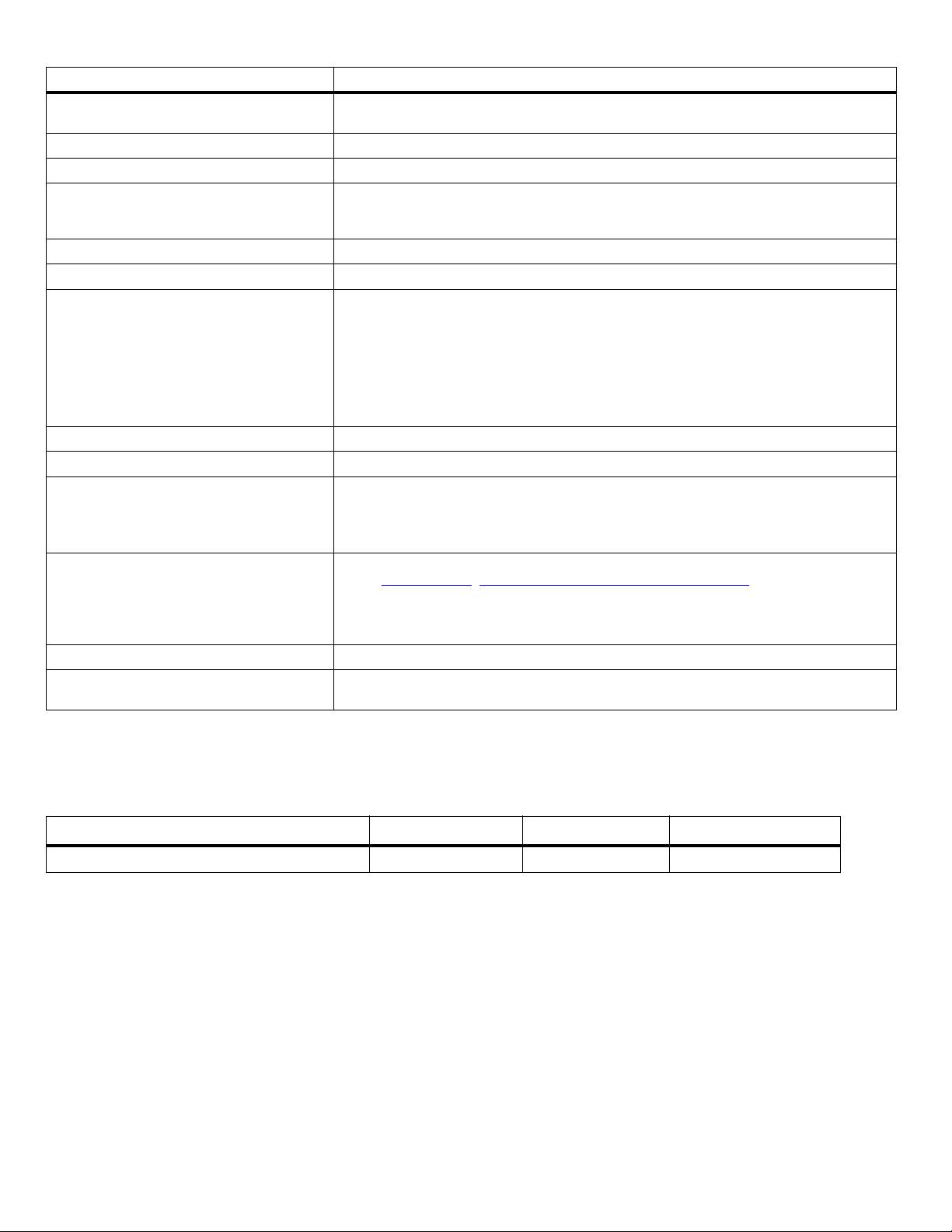
Table 1 Drive specifications summary
Drive specification
Formatted (512 bytes/sector)
Guaranteed sectors
Heads
Discs
Bytes per logical sector
Bytes per physical sector
Recording density, KBPI (Kb/in max)
Track density, KTPI (ktracks/in, 0 skew)
Areal density, (Gb/in2, @ 0 skew mid-disk)
Spindle speed (RPM)
Internal data transfer rate (Mb/s max)
Sustained data transfer rate OD (MiB/s max)
I/O data-transfer rate (MB/s max)
ATA data-transfer modes supported
Cache buffer
Weight: (maximum)
Average latency
Power-on to ready (sec) (typ/max)
Standby to ready (sec) (typ/max)
Startup current (typical) 12V (peak)
Voltage tolerance (including noise)
Non-Operating temperature –40° to 70°C (Ambient Temperature, see sections 2.6 and 2.11)
Operating temperature
Operating temperature
Temperature gradient (°C per hour max)
Relative humidity
Relative humidity gradient 30% per hour max
Altitude, operating
*
#
*
*
ST8000VX004
8TB
(see Section 2.2)
10
5
512
4096
2509
371
930
7200
2850
200 (210 MB/s max)
600
PIO modes 0–4
Multiword DMA modes 0–2
Ultra DMA modes 0–6
256MB (262,144KB)
716g (1.579 lb)
4.16ms
23/30
23/30
1.8A
5V +10/-5%
12V ±10%
5°C
70°C
20°C (operating)
30°C (nonoperating)
5% to 95% (operating)
5% to 95% (nonoperating)
–304.8 m to 3,048 m
(–1000 ft to 10,000+ ft)
Seagate SkyHawk Serial ATA Product Manual, Rev. B 6
Drive specification
Altitude, nonoperating
(below mean sea level, max)
ST8000VX004
–304.8 m to 12,192 m
(–1000 ft to 40,000+ ft)
Operational Shock (max at 2 ms - typical) Read 70 Gs / Write 40 Gs
Non-Operational Shock (max at 2 ms - typical) 300 Gs
5–22 Hz: 0.25 Gs, Limited displacement
Vibration, operating
22–350 Hz: 0.50 Gs
350–500 Hz: 0.25 Gs
Operation Rotational vibration 20–1500Hz: 12.5 rads/s²
Vibration, nonoperating 10–500 Hz: 5.0 Grms ref
Drive acoustics, sound power (bels)
2.8 (typical)
Idle
During periods of drive idle, some offline activity may occur according to the
3.0 (max)
SMART specification, which may increase acoustic and power to operational levels.
Performance seek
Nonrecoverable read errors 1 sector per 10
Annualized Failure Rate (AFR)
*
3.2 (typical)
3.4 (max)
15
bits read
0.87% based on 8760 POH
Maximum rate of <180TB/year
Maximum Rated Workload
*
Workloads exceeding the annualized rate may degrade the drive MTBF and impact product
reliability. The Annualized Workload Rate is in units of TB per year, or TB per 8760 power on
hours. Workload Rate = TB transferred * (8760 / recorded power on hours).
To determine the warranty for a specific drive, use a web browser to access the following web
page: http://www.seagate.com/support/warranty-and-replacements/.
Warranty
From this page, click on the “Is my Drive under Warranty” link. The following are required to
be provided: the drive serial number, model number (or part number) and country of
purchase.The system will display the warranty information for the drive.
Load-unload cycles (command controlled) 300,000
Supports Hotplug operation per
Serial ATA Revision 3.3 specification
#
One GB equals one billion bytes when referring to hard drive capacity. Accessible capacity may vary depending on operating environment and formatting.
* See Section 2.11, "Reliability" for rated MTBF device operating condition requirements.
Yes
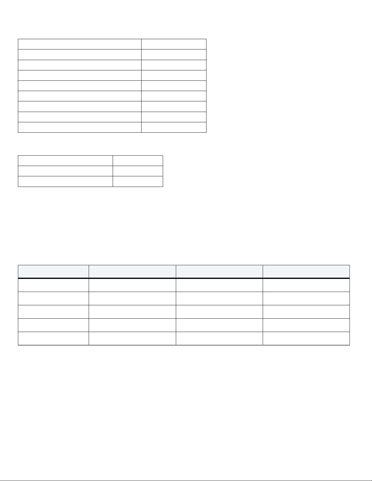
2.2Formatted capacity
ST models Formatted capacity* Guaranteed sectors Bytes per logical sector
ST8000VX004 8TB 15,628,053,168 512
* One GB equals one billion bytes when referring to hard drive capacity. Accessible capacity may vary depending on operating environment and formatting.
2.2.1 LBA mode
When addressing these drives in LBA mode, all blocks (sectors) are consecutively numbered from 0 to n–1, where n is the number of
guaranteed sectors as defined above.
See Section 4.3.1, "Identify Device command" (words 60-61 and 100-103) for additional information about 48-bit addressing
support of drives with capacities over 137GB.
Seagate SkyHawk Serial ATA Product Manual, Rev. B 7
2.3 Recording and interface technology
Interface Serial ATA (SATA)
Recording method Perpendicular
Recording density, KBPI (Kb/in max) 2509
Track density, KTPI (ktracks/in, 0 Skew) 371
Areal density (Gb/in2, @ 0 skew mid-disk) 930
Spindle speed (RPM) (± 0.2%) 7200
Internal data transfer rate (Mb/s max) 2850
Sustained data transfer rate (MiB/s max) 200 (210 MB/s max)
I/O data-transfer rate (MB/s max) 600 (Ultra DMA mode 5)
2.4 Start/stop times
Power-on to Ready (sec) (typ/max) 23/30
Standby to Ready (sec) (typ/max) 23/30
Ready to spindle stop (sec) (max) 23
2.5 Power specifications
The drive receives DC power (+5V or +12V) through a native SATA power connector. See Figure 2 on page 21 .
2.5.1 Power consumption
Power requirements for the drives are listed in Tab le 2 . Typical power measurements are based on an average of drives tested, under
nominal conditions, using 5.0V and 12.0V input voltage at 25°C ambient temperature.
Table 2 DC Power Requirements
Power Dissipation Avg (25°C) (Watts) Avg 5V typical (Amps) Avg 12V typical (Amps)
Spinup (max) 1.8A
1
Idle
Operating
*
Standby
Sleep 0.96 0.166 0.011
1. During periods of drive idle, some offline activity may occur according to the S.M.A.R.T. specification, which may increase acoustic and power to operational
levels.
* Based on IDEMA 3 stream workload
7.06 0.233 0.501
8.73 0.332 0.590
0.96 0.166 0.011
Seagate SkyHawk Serial ATA Product Manual, Rev. B 8
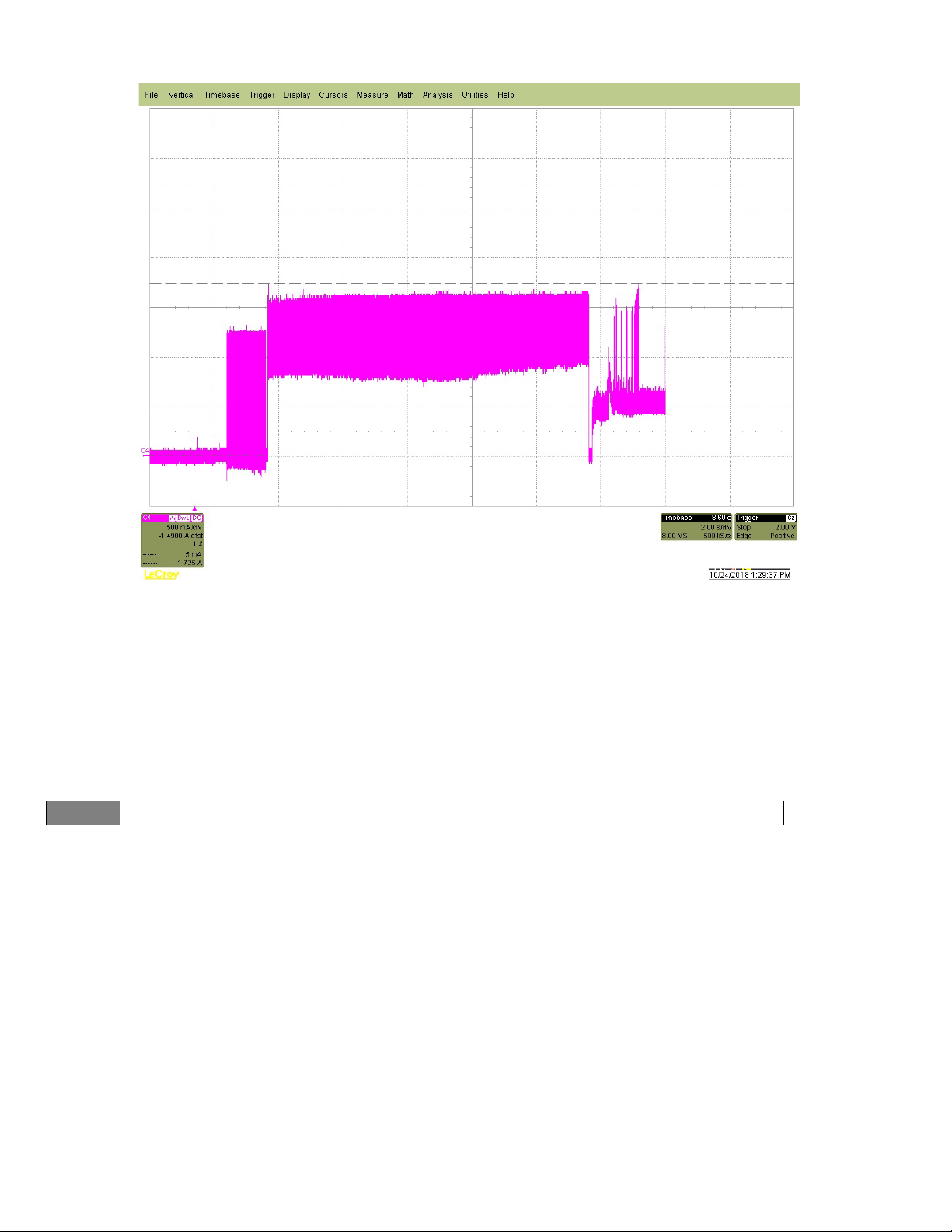
2.5.1.1 Typical current profiles
Figure 1. Typical 12V startup and operation current profile
2.5.2 Conducted noise
Input noise ripple is measured at the host system power supply across an equivalent 80-ohm resistive load on the +12 V line or an
equivalent 15-ohm resistive load on the +5V line.
• Using 12V power, the drive is expected to operate with a maximum of 120mV peak-to-peak square-wave injected noise at up to
10MHz.
• Using 5V power, the drive is expected to operate with a maximum of 100mV peak-to-peak square-wave injected noise at up to
10MHz.
Note
Equivalent resistance is calculated by dividing the nominal voltage by the typical RMS read/write current.
2.5.3 Voltage tolerance
Voltage tolerance (including noise):
5V +10/ -5% 12V ± 10%
Seagate SkyHawk Serial ATA Product Manual, Rev. B 9
 Loading...