

Page 1
Product Manual
Lyrion Series IDE
ST760211DE
ST730212DE
100462437
Rev. B
May 2007
Page 2

Revision history
Revision Date Sheets affected or comments
Rev. A 01/04/07 Initial Release.
Rev. B 05/01/07 Front cover, 1, 3-4, 9-11, 21-22, 26 and 28-31.
Copyright © 2007 Seagate Technology LLC. All rights reserved. Printed in U.S.A.
Publication number: 100462437, Rev. B May 2007
Seagate, Seagate Technology and the Wave logo are registered trademarks of Seagate Technology LLC
in the United States and/or other countries. Lyrion Series, SeaTools and SeaTDD are either trademarks or
registered trademarks of Seagate Technology LLC or one of its affiliated companies in the United States
and/or other countries. All othe r trademarks or register ed trademarks are the p roperty of their respectiv e
owners.
One gigabyte, or GB, equals one billion bytes when referring to hard drive capacity. Accessible capacity
may vary depending on operating environment and formatting. Seag ate reserves th e right to change, with
out notice, product offerings or specifications.
-
Page 3

Contents
1.0 Introduction. . . . . . . . . . . . . . . . . . . . . . . . . . . . . . . . . . . . . . . . . . . . . . . . . . . . . . . . . . . . . . . . . . . 1
1.1 Disclaimer . . . . . . . . . . . . . . . . . . . . . . . . . . . . . . . . . . . . . . . . . . . . . . . . . . . . . . . . . . . . . . 2
1.2 Drive care . . . . . . . . . . . . . . . . . . . . . . . . . . . . . . . . . . . . . . . . . . . . . . . . . . . . . . . . . . . . . . 2
2.0 Drive specifications . . . . . . . . . . . . . . . . . . . . . . . . . . . . . . . . . . . . . . . . . . . . . . . . . . . . . . . . . . . . 3
2.1 Overview . . . . . . . . . . . . . . . . . . . . . . . . . . . . . . . . . . . . . . . . . . . . . . . . . . . . . . . . . . . . . . . 3
2.2 Formatted capacity . . . . . . . . . . . . . . . . . . . . . . . . . . . . . . . . . . . . . . . . . . . . . . . . . . . . . . . 4
2.3 Default logical geometry . . . . . . . . . . . . . . . . . . . . . . . . . . . . . . . . . . . . . . . . . . . . . . . . . . . 4
2.4 Recording and interface technology . . . . . . . . . . . . . . . . . . . . . . . . . . . . . . . . . . . . . . . . . . 5
2.5 Physical characteristics . . . . . . . . . . . . . . . . . . . . . . . . . . . . . . . . . . . . . . . . . . . . . . . . . . . 5
2.6 Time to ready. . . . . . . . . . . . . . . . . . . . . . . . . . . . . . . . . . . . . . . . . . . . . . . . . . . . . . . . . . . . 5
2.7 Power specifications . . . . . . . . . . . . . . . . . . . . . . . . . . . . . . . . . . . . . . . . . . . . . . . . . . . . . . 6
2.7.1 Power consumption . . . . . . . . . . . . . . . . . . . . . . . . . . . . . . . . . . . . . . . . . . . . . . . 6
2.7.2 Conducted noise . . . . . . . . . . . . . . . . . . . . . . . . . . . . . . . . . . . . . . . . . . . . . . . . . 8
2.7.3 Voltage tolerance and Maximum current . . . . . . . . . . . . . . . . . . . . . . . . . . . . . . . 8
2.7.4 Power-management modes. . . . . . . . . . . . . . . . . . . . . . . . . . . . . . . . . . . . . . . . . 9
2.8 Environmental specifications. . . . . . . . . . . . . . . . . . . . . . . . . . . . . . . . . . . . . . . . . . . . . . . 10
2.8.1 Ambient temperature . . . . . . . . . . . . . . . . . . . . . . . . . . . . . . . . . . . . . . . . . . . . . 10
2.8.2 Temperature gradient. . . . . . . . . . . . . . . . . . . . . . . . . . . . . . . . . . . . . . . . . . . . . 10
2.8.3 Humidity. . . . . . . . . . . . . . . . . . . . . . . . . . . . . . . . . . . . . . . . . . . . . . . . . . . . . . . 10
2.8.4 Altitude. . . . . . . . . . . . . . . . . . . . . . . . . . . . . . . . . . . . . . . . . . . . . . . . . . . . . . . . 10
2.8.5 Shock. . . . . . . . . . . . . . . . . . . . . . . . . . . . . . . . . . . . . . . . . . . . . . . . . . . . . . . . . 11
2.8.6 Vibration. . . . . . . . . . . . . . . . . . . . . . . . . . . . . . . . . . . . . . . . . . . . . . . . . . . . . . . 11
2.8.7 Corrosive environment. . . . . . . . . . . . . . . . . . . . . . . . . . . . . . . . . . . . . . . . . . . . 13
2.9 Acoustics . . . . . . . . . . . . . . . . . . . . . . . . . . . . . . . . . . . . . . . . . . . . . . . . . . . . . . . . . . . . . . 14
2.10 Electromagnetic immunity . . . . . . . . . . . . . . . . . . . . . . . . . . . . . . . . . . . . . . . . . . . . . . . . . 14
2.11 Reliability . . . . . . . . . . . . . . . . . . . . . . . . . . . . . . . . . . . . . . . . . . . . . . . . . . . . . . . . . . . . . . 14
2.12 Agency certification . . . . . . . . . . . . . . . . . . . . . . . . . . . . . . . . . . . . . . . . . . . . . . . . . . . . . . 15
2.12.1 Safety certification . . . . . . . . . . . . . . . . . . . . . . . . . . . . . . . . . . . . . . . . . . . . . . . 15
2.12.2 Electromagnetic compatibility. . . . . . . . . . . . . . . . . . . . . . . . . . . . . . . . . . . . . . . 15
2.12.3 European Union Restriction of Hazardous Substances (RoHS) Directive. . . . . 15
2.12.4 China Restriction of Hazardous Substances (RoHS) Directive . . . . . . . . . . . . . 16
2.12.5 FCC verification . . . . . . . . . . . . . . . . . . . . . . . . . . . . . . . . . . . . . . . . . . . . . . . . . 16
3.0 Configuring and mounting the drive . . . . . . . . . . . . . . . . . . . . . . . . . . . . . . . . . . . . . . . . . . . . . 19
3.1 Handling and static discharge precautions . . . . . . . . . . . . . . . . . . . . . . . . . . . . . . . . . . . . 19
3.2 Drive installation . . . . . . . . . . . . . . . . . . . . . . . . . . . . . . . . . . . . . . . . . . . . . . . . . . . . . . . . 21
3.3 Mounting considerations . . . . . . . . . . . . . . . . . . . . . . . . . . . . . . . . . . . . . . . . . . . . . . . . . . 22
4.0 Interface description . . . . . . . . . . . . . . . . . . . . . . . . . . . . . . . . . . . . . . . . . . . . . . . . . . . . . . . . . . 23
4.1 Connector interface signals and connector pins . . . . . . . . . . . . . . . . . . . . . . . . . . . . . . . . 23
4.2 Supported ATA commands . . . . . . . . . . . . . . . . . . . . . . . . . . . . . . . . . . . . . . . . . . . . . . . . 25
4.2.1 Identify Device command. . . . . . . . . . . . . . . . . . . . . . . . . . . . . . . . . . . . . . . . . . 27
4.2.2 Set Features command . . . . . . . . . . . . . . . . . . . . . . . . . . . . . . . . . . . . . . . . . . . 30
4.3 Register default values . . . . . . . . . . . . . . . . . . . . . . . . . . . . . . . . . . . . . . . . . . . . . . . . . . . 31
5.0 Seagate Technology support services. . . . . . . . . . . . . . . . . . . . . . . . . . . . . . . . . . . . . . . . . . . . 33
Lyrion Series IDE Product Manual, Rev. B i
Page 4

ii Lyrion Series IDE Product Manual, Rev. B
Page 5

List of Figures
Figure 1. Lyrion Series (IDE interface) disc drive . . . . . . . . . . . . . . . . . . . . . . . . . . . . . . . . . . . . . . . . . . 1
Figure 2. Typical 3.3V startup and operation current profile . . . . . . . . . . . . . . . . . . . . . . . . . . . . . . . . . . 7
Figure 3. Location where tri-axial accelerometer will be placed on Lyrion Series drives. . . . . . . . . . . . 11
Figure 4. Drive axis definition for Lyrion Series drives. . . . . . . . . . . . . . . . . . . . . . . . . . . . . . . . . . . . . . 11
Figure 5. Lyrion Series breather hole location . . . . . . . . . . . . . . . . . . . . . . . . . . . . . . . . . . . . . . . . . . . . 19
Figure 6. Lyrion Series proper handling example . . . . . . . . . . . . . . . . . . . . . . . . . . . . . . . . . . . . . . . . . 19
Figure 7. Lyrion Series mechanical dimensions—top, side and end view. . . . . . . . . . . . . . . . . . . . . . . 21
Figure 8. Lyrion Series Area for Protective Mounting . . . . . . . . . . . . . . . . . . . . . . . . . . . . . . . . . . . . . . 22
Lyrion Series IDE Product Manual, Rev. B iii
Page 6

iv Lyrion Series IDE Product Manual, Rev. B
Page 7
1.0 Introduction
This manual describes the functional, mechanical and interface specifications for the following Seagate® Lyrion
®
Series
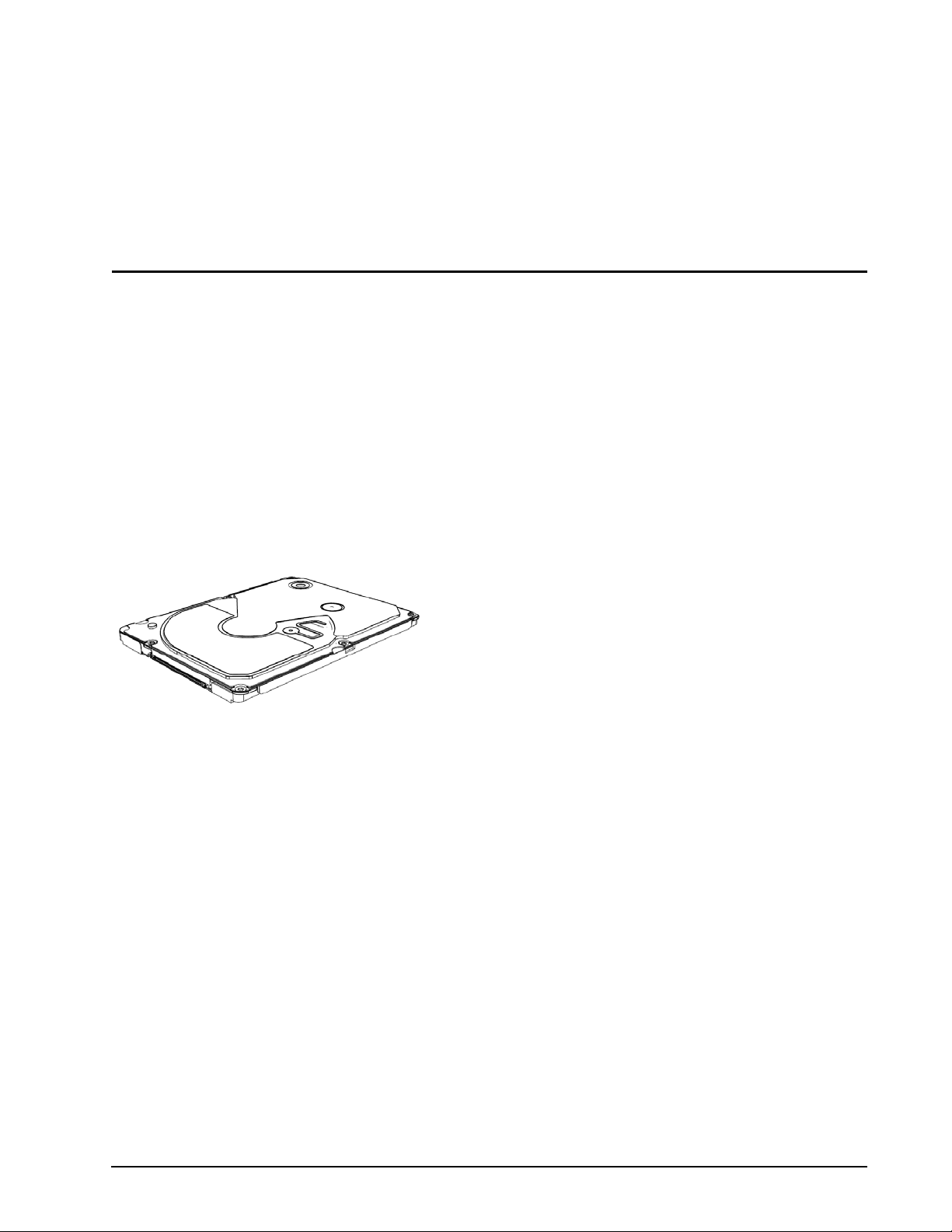
• ST760211DE-60GB, ST730212DE-30GB disc drives with an IDE interface.
These drives provide the following key features.
• 3,600-RPM spindle speed and a 2-Mbyte bu ffer combined for superior read/write performance.
• Quiet operation. Fluid Dynamic Bearing (FDB) motor.
• Perpendicular recording heads and EPRML techn ology, which provide the drives with increase d areal density.
• State-of-the-art cache and on-the-fly error-correction algorithms.
• 1500 G nonoperating shock, and 500 G operating shock.
• SeaTools™ diagnostic software performs a drive self-test that eliminates unnecessary drive returns.
IDE drives:
Figure 1. Lyrion Series (IDE interface) disc drive
Lyrion Series IDE Product Manual, Rev. B 1
Page 8

1.1 Disclaimer
Seagate Technology LLC makes no warranties whatsoever, including any warranty of merchantability, noninfringement, fitness for any particular purpose, or any warranty otherwise arising out of any proposal,
specification or sample. Seagate may not be held liable for any direct, indirect, incidental, special, exemplary,
or consequential damages (including, but not limited to, loss of use, data, or profits; procurement of substitute
goods or services; or business interruptions) however caused and on any theory of liability, whether in contract,
strict liability, or tort (including negligence or otherwise) arising in any way from the use of this kit, even if
advised of the possibility of such damage.
1.2 Drive care
Do not use the Lyrion Serie s disc drives out side of the range s of envi ronment al condition s found in Section 2.8,
"Environmental specifications." Doing so may void the warranty of the Lyrion Series disc drive.
2 Lyrion Series IDE Product Manual, Rev. B
Page 9
2.0 Drive specifications
Unless otherwise noted, all specifications are measured under ambient conditions, at 25°C, and nominal
power. For convenience, the phrases the drive and this drive are used throughout this manual to indicate
ST760211DE and ST730212DE model drives.
2.1 Overview
The specifications listed in this table are for quick reference. For details on specification measurement or
definition, see the appropriate section of this manual.
Table 1: Specifications
Drive specification ST760211DE ST730212DE
Formatted Gbytes 60 30
Guaranteed sectors 117,210,240 58,605,120
Bytes per sector (logical) 512
Cache (Mbytes) 2
Recording density, BPI (bits/inch average) 1,025,000
Track density. TPI (tracks/inch average) 165,000
Areal density (Gbits/inch2 average) 169
Spindle speed (RPM) 3,600
Internal data transfer rate OD (Mbits/sec max) 350
Sustained data transfer rate OD (Mbytes/sec) 24.5
I/O data-transfer rate (Mbytes/sec max) 66.7 (UDMA 4)
ATA data-transfer modes supported PIO modes 0–4;
Height 5.0 + 0.15 mm(0.1968 + 0.006 inches)
Width 54.0 +/-0.3 mm (2.1260 +/-0.0118 inches)
Length 71.0 +/-0.3 mm (2.7953 +/-0.0118 inches)
Weight 48.0 gm - 0.1058 lb. (typ)
Average latency (msec) 8.3
Power-on to ready (sec typical) 1.8
Standby to ready (sec typical) 1.8
Startup power (peak at 3.3v) (maximum RMS in 10ms window) 1.15 W
Read/write power (typical 3.3V) 1.0/0.9 W
Performance idle power (typical 3.3V) 0.5 W
Low power idle power (typical 3.3V) 0.3 W
Standby/Sleep power (typical 3.3V) 0.08 W
Voltage tolerance (including noise) 3.3V ± 5%
Ambient temperature 0° to 60°C (operating)
Multiword DMA modes 0-2;
Ultra DMA modes 0–4
–40° to 70°C (nonoperating)
Lyrion Series IDE Product Manual, Rev. B 3
Page 10
Table 1: Specifications
Drive specification ST760211DE ST730212DE
Temperature gradient (°C per hour max) 20°C (operating)
Relative humidity (noncondensing) 5% to 90% (operating)
Relative humidity gradient 30% per hour max
Wet bulb temperature (°C max) 33°C (operating)
Altitude, operating –60.98 m to 3,048 m (–200 ft to 10,000+ ft)
Altitude, nonoperating (below mean sea level, max) –60.98 m to 12,192 m (–200 ft to 40,000+ ft)
Shock, operating (Gs max at 2 msec) 500
Shock, nonoperating (Gs max at 1 msec) 1500
Vibration, operating
(max displacement may apply below 10 hz)
Vibration, nonoperating
(max displacement may apply below 22 hz)
Idle sound power (bels) (typical) 1.6
Operational sound power (bels) (typical) 2.2
Nonrecoverable read errors 1 per 1014 bits read
Load/Unload (LUL) cycles 20,000 power loss
30°C (nonoperating)
5% to 95% (nonoperating)
40°C (nonoperating)
1.0 Gs (0 to peak, 10–500 Hz) @ 2 oct/min sweep rate
5.0 Gs (0 to peak, 10–500 Hz) @ 0.5 oct/min sweep rate
2.2 Formatted capacity
Model Formatted
capacity
ST760211DE 60 Gbytes 117,210,240 512
ST730212DE 30 Gbytes 58,605,120 512
LBA mode addressing
When addressing these drives in LBA mode, all blocks (sectors) are consecutively numbered from 0 to n–1,
where n is the number of guaranteed sectors as defined above.
Guaranteed
sectors
Bytes per
sector (logical)
2.3 Default logical geometry
Model Cylinders Heads Sectors
ST760211DE 116,280 16 63
ST730212DE 58,149 16 63
4 Lyrion Series IDE Product Manual, Rev. B
Page 11
2.4 Recording and interface technology
Technology Specification
Interface IDE (Parallel ATA)
Recording method Perpendicular Magnetic Recording
Recording density BPI (bits/inch average) 1,025,000
Track density TPI (tracks/inch average) 165,000
Areal density (Gbits/inch2 average) 169
Spindle speed (RPM) (± 0.2%) 3,600
Internal data-transfer rate OD (Mbits/sec max) 350
Sustained data transfer rate OD (Mbytes/sec max) 24.5
I/O data-transfer rate (Mbytes/sec max) 66.7 (UDMA 4)
Cache buffer (Mbytes) 2
2.5 Physical characteristics
Height (mm)
(inches)
Width (mm)
(inches)
Length (mm)
(inches)
Typical weight (grams)
(pounds)
Interface Connector 40-way ZIF
5.0 + 0.15
0.1968 + 0.006
54.0 +/-0.3
2.1260 +/-0.0118
71.0 +/-0.3
2.7953 +/-0.0118
48.0 (typ)
0.1058 lb. (typ))
2.6 Time to ready
Time to ready Typical
Power-On to Ready (sec) 1.8
Standby to Ready (sec) 1.8
Lyrion Series IDE Product Manual, Rev. B 5
Page 12

2.7 Power specifications
The drive receives DC power (+3.3V) through the ZIF connector (IDE interface).
2.7.1 Power consumption
Power requirements for the drives are listed in the t able on page 7. Typical power measurements are ba sed o n
an average of drives tested, under nominal co nditions, using +3.3V inp ut voltag e at 25°C ambient temperatur e.
• Startup mode
Startup power is measured from the time of power-on to the time that the drive sp indle reaches operating speed.
• Seek mode
During seek mode, the read/write actuator arm moves towar d a specific position on the disc surface and does
not execute a read or write operation. Servo electronics are active. Seek power is measur ed base d o n thr ee
random seek operations every 100 msecs.
• Read/write mode
Read/write power is measured with the heads on track, while the head is reading/writing from/to disc. It is
performed with 100 percent duty cycle of read/write operation.
• Performance Idle mode
During Performance Idle mode, the heads are on track but no reading or writing is done . The spindle motor is
spinning at full speed.
• Low power idle mode
During Low power Idle mode, the heads are unloaded but the spindle motor is spinning at full speed. Servo
and read/write electronics are in powered down mode.
• Standby / Sleep mode
During Standby/Sleep mode, the spindle motor is not spinning, and the servo and read/write electronics are
in powered down mode.
6 Lyrion Series IDE Product Manual, Rev. B
Page 13
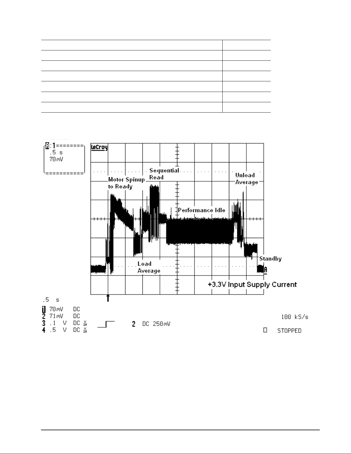
Table 2: DC power
Power Consumption at 3.3V Average (W)
Startup (max*) 1.15
Read 1.0
Write 0.9
Performance idle (typical) 0.5
Low power idle (typical) 0.3
Standby/Sleep (typical) 0.08
*Maximum is the average of the peak value in 10 msec window
2.7.1.1 Typical current profile
Figure 2. Typical 3.3V startup and operation current profile
Lyrion Series IDE Product Manual, Rev. B 7
Page 14

2.7.2 Conducted noise
Input noise ripple is measured at the host system powe r supply across an equivalent 15-ohm resistive load on
the +3.3 volt line.
Using 3.3-volt power, the drive is expected to operate with a maximum o f 70 mV peak-to-peak square-w ave
injected noise at up to 20 MHz.
Note. Equivalent resistance is calculated by dividing the nominal voltage by the typical RMS read/write
current.
2.7.3 Volt a ge tolerance and Maximum current
Voltage tolerance (including noise):
3.3V ± 5%
Maximum Current (peak-to-peak):
500mA
8 Lyrion Series IDE Product Manual, Rev. B
Page 15

2.7.4 Power-management modes
The drive provides programmable power management to provide greater energy efficiency. The drive features
the following power-management modes:
Table 3: Power-management modes
Power modes Heads Spindle Buffer
Active (read/write/seek) Tracking Rotating Enabled
Idle, performance Tracking Rotating Enabled
Idle, low power Parked Rotating Disabled
Standby/Sleep Parked Stopped Disabled
• Active mode
The drive is in Active mode during the read/write and seek operations.
• Performance idle mode
The drive enters this mode once the read/write/seek activity is completed. The buffer remains enabled, and
the drive accepts all commands and returns to Active mode any time disc access is necessary.
• Low power idle mode
Drive enters Low Power Idle mode from Performance Idle mode when the Advanced Power Management
Level is set between 80h and FD h, and the Idle timer r eaches 15 seconds. Disc is spinning and heads a re
parked and drive accepts all commands and returns to Active mode any time disc access is necessary.
• Standby/Sleep mode
The drive enters Standby mode when the host sends a Standby Immediate comman d. In Standb y mo de, th e
drive buffer is disabled, the heads are parked and the spindle is at rest. The drive accepts all commands and
returns to Active mode any time disc access is necessary.
Lyrion Series IDE Product Manual, Rev. B 9
Page 16

2.8 Environmental specifications
2.8.1 Ambient temperature
Ambient temperature is defined as the temperature of the environment immediately surrounding the drive.
Actual drive case temperature should not exceed
temperature of the drive operating at 60°C ambient may hit a maximum of 70°C at certain parts of the casing.
Above 1,000 feet (305 meters), the maximum operating temperature is derated linearly by 1°C every 1000 feet.
Operating 0° to 60°C (32° to 140°F) (70°C max case temperature)
Nonoperating –40° to 70°C (–40° to 158°F)
2.8.2 Temperature gradient
Operating 20°C per hour (36°F per hour max), without condensation
Nonoperating 30°C per hour (54°F per hour max), without condensation
2.8.3 Humidity
2.8.3.1 Relative humidity
70°C (158°F) within the operating ambient conditions. Case
Operating 5% to 90% noncondensing (30% per hour max)
Nonoperating 5% to 95% noncondensing (30% per hour max)
2.8.3.2 Wet bulb temperature
Operating 33°C (91.4°F max) [1]
Nonoperating 40°C (104°F max) [2]
[1] Operating: Wet bulb temperature is calculated by the operating Temperature and the Relative Humidity levels.
[2] Nonoperating: Wet bulb temperature is calculated by the nonoperating Temperature and the Relative Humidity levels.
2.8.4 Altitude
Operating –60.98 m to 3,048 m (–200 ft to 10,000+ ft)
Nonoperating –60.98 to 12,192 m (–200 ft to 40,000+ ft)
10 Lyrion Series IDE Product Manual, Rev. B
Page 17

2.8.5 Shock
All shock measurements in this section are carried out at drive level. For all linear shock test, operating or
nonoperating, the input shock level is measured at the fra m e of th e d rive at the sp ecif ic location as indicated in
Figure 3 below.
Shock Monitoring PositionShock Monitoring Position
Figure 3. Location where tri-axial accelerometer will be placed on Lyrion Series drives
All shock test cover all the 6 directions, +/- x, y and z axes. The drive axis definition in shown in Figure 4 below.
-Z
-Y
-X
+X
+Y
+Z
Figure 4. Drive axis definition for Lyrion Series drives
2.8.5.1 Operating shock
The drive is subjected to 10 shocks for ea ch dir ec tio n. Dur ing th e sh oc ks, the re mu st be a min im um dela y of 3
seconds between shock pulses. Soft errors and automatic retries are allowed during the test. No data loss or
permanent damage occurs during a half sine shock pulse of:
500 G, 2 msec
2.8.5.2 Nonoperating shock
The nonoperating shock level that the drive can experience without incurring any physical damage when subsequently put into operation is 1500 Gs. The same applies for shock levels of 1500 G, 1 msec pulse duration
on fresh drives for each level.
2.8.6 Vibration
All vibration specifications assume that the drive is mounted securely in a fixture that does not have fixture
resonances in the frequency test range.
Lyrion Series IDE Product Manual, Rev. B 11
Page 18

2.8.6.1 Operating sweep sine vibration
The following lists the maximum operating sweep sine vibration levels that the drive may experience while
meeting the performance standards specified. It consists of a forward and backward sweep from 10 Hz to
500
Hz to 10 Hz. The drive operates without a hard error while being subjected to the following vibration levels.
10 Hz to 500 Hz @ 2 oct/min 1.0 Gs (0 to pk). Maximum displacement may apply below 10 Hz.
2.8.6.2 Operating random vibration
The test consists of 30 minutes of random vibration using the power spectral density (PSD) levels specified in
the table below. The vibration test level is 0.67
Gs RMS. The drive operates without a hard error while being
subjected to the following vibration levels.
Table 4: Operating random vibration profile
Frequency (Hz) G2/Hz
17 1.1 x E-03
45 1.1 x E-03
48 8.0 x E-03
62 8.0 x E-03
65 1.0 x E-03
150 1.0 x E-03
200 5.0 x E-04
500 5.0 x E-04
2.8.6.3 Nonoperating sweep sine vibration
The following table lists the maximum nonoperating sweep sine vibration levels that the drive may experience
while meeting the performance standards specified. It consists of a forward and backward sweep from 5 Hz to
500 Hz to 5 Hz. The drive does not incur any physical damage when subsequently put into operation.
10 Hz to 500 Hz @ 0.5 oct/min 5.0 Gs (0 to pk). Maximum displacement may apply below 22 Hz.
5 Hz to 10 Hz 25.4 mm peak to peak displacement.
12 Lyrion Series IDE Product Manual, Rev. B
Page 19

2.8.6.4 Nonoperating random vibration
The test consists of 15 minutes of random vibration using the power spectral density (PSD) levels specified in
the table below. The vibration test level is 3.01 Gs RMS. The drive does not incur any physical damage when
subsequently put into operation.
Table 5: Nonoperating random vibration profile.
Frequency (Hz) G2/Hz
2.5 1.0 x E-03
5 3.0 x E-02
40 1.8 x E-02
500 1.8 x E-02
2.8.7 Corrosive enviro nment
Seagate electronic drive components pass accelerated corrosio n testing equi valent to ten years of expo sure to
light industrial environments containing sulfurous gases, chlorine and nitric oxide, classes G and H per ASTM
B845. However, this accelerated testing cannot duplicate every potential application environment.
Users should use caution exposing any electronic components to uncontrolled chemical pollutants and corrosive chemicals as electronic drive component reliability can be affected by the installation environment. The silver, copper, nickel and gold films used in Seagate products are especially sensitive to the presence of sulfide,
chloride, and nitrate contaminants. Sulfur is found to be the most da maging. In addi tion, electronic comp onent s
should never be exposed to condensing water on the surface of the printed circuit board assembly (PCBA) or
exposed to an ambient relative humidity greater than 95 percent. Materials used in cabinet fabrication, such as
vulcanized rubber, that can outgas corrosive compounds should be minimized or eliminated. The useful life of
any electronic equipment may be extended by replacing materials near circuitry with sulfide-free alternatives.
Lyrion Series IDE Product Manual, Rev. B 13
Page 20

2.9 Acoustics
Drive acoustics are measured as overall A-weighted acoustic sound power levels (no pure tones). Discrete
tone penalties are added to the A-weighted sound power (LW) with the following formula only when determin
ing compliance:
LWt(spec) == LW + 0.1Pt + 0.3 < 4.0 (Bels)
where
LW = A-weighted sound power level
pt == Value of discrete tone penalty [==dLt-6.0 (dBA)]
dLt = Tone-to-noise ratio taken in accordance with ISO 7779 at each octave band.
All measurements are consistent with ISO document 7779. Sound power measurements are taken under
essentially free-field conditions over a reflecting plane. For all tests, the drive is oriented with the cover facing
upward.
Table 6: Drive level acoustics
Acoustic mode
Idle Operational
1.6 bels (typ) 2.2 bels (typ)
)
-
2.10 Electromagnetic immunity
When properly installed in a representative host syst em, the drive operates without errors or degradation in
performance when subjected to the radio frequency (RF) environments defined in the follo wing table:
Table 7: Electromagnetic immunity
Performance
Test Description
Radiated RF immunity 80 to 1,000 MHz, 3 V/m,
80% AM with 1 kHz sine
900 MHz, 3 V/m, 50% pulse modulation @ 200
Hz
Electrical fast transient ± 1 kV on AC mains, ± 0.5 kV on external I/O B EN 61000-4-4: 95
Surge immunity ± 1 kV differential, ± 2 kV common, AC mains B EN 61000-4-5: 95
Conducted RF immunity 150 kHz to 80 MHz, 3 Vrms, 80% AM with 1
kHz sine
Voltage dips, interrupts 0% open, 5 seconds
0% short, 5 seconds
40%, 0.10 seconds
70%, 0.01 seconds
level
A EN 61000-4-3: 96
A EN 61000-4-6: 97
C
C
C
B
Reference
standard
ENV 50204: 95
EN 61000-4-11: 94
2.11 Reliability
Measurement type Specification
Nonrecoverable read errors 1 per 1014 bits read, max.
Load/Unload (LUL) cycles 20,000 power loss
14 Lyrion Series IDE Product Manual, Rev. B
Page 21

2.12 Agency certification
2.12.1 Safety certification
The drives are recognized in accordance with UL60950-1, CAN/CSA-C22.2 No.60950-1, EN60950 and IEC
60950.
2.12.2 Electromagnetic compatibility
Hard drives that display the CE mark comply with the European Union (EU) requirements specified in the Electromagnetic Compatibility Directive (89/336/EEC). Testing is performed to the levels specified by the product
standards for Information Technology Equipment (ITE). Emission levels a re define d by EN 5502 2, Cla ss B and
the immunity levels are defined by EN 55024.
Seagate uses an independent laboratory to confirm compliance with the EC directives specified in the previous
paragraph. Drives are tested in representative end-us er systems. Although CE-marked Seagate drives comply
with the directives when used in the test systems, we cannot guarantee that all systems will comply with the
directives. The drive is designed for operation inside a properly designed enclosure, with properly shielded I/O
cable (if necessary) and terminators on all unused I/O ports. Computer manufacturers and system integrators
should confirm EMC compliance and provide CE marking for their products.
Korean RRL
If these drives have the Korea Ministry of Information and Communication (MIC) logo, they comply with paragraph 1 of Article 11 of the Electromagnetic Compatibility control Regulation and meet the Electromagnetic
Compatibility (EMC) Framework requirements of the Radio Research Laboratory (RRL) Ministry of Information
and Communication Republic of Korea.
These drives have been tested and comply with the Electromagnetic Inte rference /Electr omagnetic Susce ptibil ity (EMI/EMS) for Class B products. Drives are tested in a representative, end-user system by a Korean-recognized lab.
• Family name: Lyrion Series
• Certificate numbers: STX-S181 (B)
Australian C-Tick (N176)
If these models have the C-Tick marking, they comply with the Australia/New Zealand Standard AS/NZS3548
1995 and meet the Electromagnetic Compatibility (EMC) Framework requireme nts of the Australian Communi
cation Authority (ACA).
2.12.3 European Union Restriction of Hazardous Substances (RoHS) Directive
Seagate designs its products to meet environme ntal protection requirements worldwide, including regulations
restricting certain chemical substances. A new law, the European Union Restriction of Hazardous Substances
(RoHS) Directive, restricts the presence of chemical substances, including Lead, Cadmium, Mercury,
Hexavalent Chromium, PBB and PBDE, in electronic products, effective July 2006. This drive is manufactured
with components and materials that comply with the RoHS Directive.
-
Lyrion Series IDE Product Manual, Rev. B 15
Page 22

2.12.4 China Restriction of Hazardous Substances (RoHS) Directive
2.12.4
This product has an Environmental Protection Use Period (EPUP) of 20 years. The following
table contains information mandated by China's "Marking Requirements for Control of Pollution
Caused by Electronic Information Products" Standard.
"O" indicates the hazardous and toxic substance con tent of the p art (at the h omogenous mater ial level) is lower
than the threshold defined by the China RoHS MCV Standard.
中国限制危险物品的指令
“O"表示该部件(于同类物品程度上)所含的危险和有毒物质低于中国RoHS MCV标准所定义的门槛值。
"X" indicates the hazardous and toxic substance content of the part (at the homogenous material level) is over
the threshold defined by the China RoHS MCV Standard.
“
X "表示该部件(于同类物品程度上)所含的危险和有毒物质超出中国RoHS M CV标准所定义的门槛值。
2.12.5 FCC verification
These drives are intended to be contained solely with in a pe rsonal com puter or simila r enclosur e ( not attached
as an external device). As such, each drive is considered to be a subassembly even when it is individually mar
keted to the customer. As a subassembly, no Federal Communications Commission verification or certification
of the device is required.
Seagate Technology LLC has tested this device in enclosures as described above to ensure that the total
assembly (enclosure, disc drive, motherboard, power supply, etc.) does comply with the limits for a Class B
computing device, pursuant to Subpart
likely to result in interference to radio and television reception.
Radio and television interference. This equipment generates and uses radio frequency energy and if not
installed and used in strict accordanc e with the manufacturer’s instructions, may cause interference to radio
and television reception.
This equipment is designed to provide reasonable protection against such interference in a residential installation. However, there is no guarantee that interference will not occur in a particular installation. If this equipment
does cause interference to radio or television, which can be determined by turning the equipment on and off,
you are encouraged to try one or more of the following corrective measures:
• Reorient the receiving antenna.
• Move the device to one side or the other of the radio or TV.
• Move the device farther away from the radio or TV.
• Plug the computer into a different outlet so that the receiver and computer are on different branch outlets.
J, Part 15 of the FCC rules. Operation with noncertified assemblies is
-
16 Lyrion Series IDE Product Manual, Rev. B
Page 23

If necessary, you should consult your dealer or an experienced radio/television technician for additional suggestions. You may find helpful the following booklet prepared by the Federal Communications Commission:
How to Identify and Resolve Radio-Television Interference Problems. This booklet is available from the Super
intendent of Documents, U.S. Government Printing Office, Washington, DC 20402. Refer to publication number 004-000-00345-4.
-
Lyrion Series IDE Product Manual, Rev. B 17
Page 24

18 Lyrion Series IDE Product Manual, Rev. B
Page 25

3.0 Configuring and mounting the drive
This section contains the specifications and instructions for configuring and mounting the drive.
3.1 Handling and static discharge precautions
After unpacking, and before installation, the drive may be exposed to potential handling and electrostatic
discharge (ESD) hazards. Observe the following standard handling and static-discharge precautions:
Caution:
• Do not cover or seal the breather hole! Covering or sealing the breather hole may result in loss of data.
Figure 5. Lyrion Series breather hole location
• Keep the drive in the electrostatic discharge (ESD) bag until you are ready for installation to limit the drive’s
exposure to ESD.
• Before handling the drives, put on a grounded wrist strap, or grou nd yourself fre quently by touchin g the metal
chassis of a computer that is plugged into a grounded outlet. Wea r a grounded wrist strap throughout the entire
installation procedure.
• Handle the drive only by its edges or frame.
Figure 6. Lyrion Series proper handling example
• The drive is fragile—handle it with care. Do not press down on the drive top cover or attempt to use a pen to
write on the drive’s label.
• Do not apply more than 6.8N of force to the top cover.
• Always rest the drives on a padded, antistatic surface until you mount it in the system.
Lyrion Series IDE Product Manual, Rev. B 19
Page 26

• Do not remove the factory-installed labels from the drive or cover them with additional labels. Removal voids
the warranty. Some factory-installed labels contain information needed to service the drive. Other labels are
used to seal out dirt and contamination.
• If provided, store drive in the protective casing when not in use.
• Turn the power off before installing or removing the drive.
• Do not apply any force to the drive during handling or installation.
• Do not touch the connector pins or the printed circuit board.
• Do not drop the drive.
• Do not expose the drive to wet conditions.
• Do not place the drive near a strong magnetic field.
• Do not expose the drive to extreme temperatures.
• The drive may become hot during operation. Be careful when removing the drive from the host device
immediately after operation.
20 Lyrion Series IDE Product Manual, Rev. B
Page 27

3.2 Drive installation
See Figure 7 for drive mechanical dimensions.
Follow these installation precautions when inserting the drive:
• Follow instructions for the installation of data storage devices, provided with your device’s user manual.
• Do not obstruct the breather hole on the drive (see Figure 5).
• Handle the drive only by its edges or frame or designated finger grip region during mounting (see Figure 6).
Temperature Measurement Position
X
Figure 7. Lyrion Series mechanical dimensions—top, side and end view
Lyrion Series IDE Product Manual, Rev. B 21
Page 28

3.3 Mounting considerations
• Use an elastic mounting material to protect drives so as to ensure that more shock can be absorbed.
• There are guides along the side for mounting. Refer to figure on areas (r efer to Figure 8, shaded area)
where the mounting material can rest for moun tin g.
• As the drive is a sensitive device, it is not recommended to have any mounting force on the top and bottom
surface of the drive other than the recommended mounting surfaces. Mounting force on non recommended
surfaces shall not exceed 6.8N.”
• The drive can be operated in any orientation but horizontal or vertical orientation is preferred.
• Allow a minimum clearance of 0.012 inches (0.30 mm) around the entire perimeter of the drive for cooling,
with the exception of the mounting edges for better airflow.
• In case the system design warrants bending of the FPC to the hard disc drive, care should be taken to
maximize the radius.
• Mounting materials are available from many third-party vendors.
• The 40-way connector is design to meet minimum 6N Horizontal FPC retention after mating.
• The connector has a specification of 20 insertion cycles.
Note. Drive thickness (t) around Bumper Region with Screw : 3.404 ± 0.200 mm
Drive thickness (t) around Bumper Region without Screw : 3.308 ± 0.200 mm
Figure 8. Lyrion Series Area for Protective Mounting
22 Lyrion Series IDE Product Manual, Rev. B
Page 29

4.0 Interface description
The drives use the industry-standard ATA (IDE) interface. It supports ATA programmed input/output (PIO)
modes 0–4; multiword DMA modes 0–2, and Ultra DMA modes 0–4.
4.1 Connector interface signals and connector pins
The following table summarizes the signals on the 40-way ZIF ATA interface connector.
Table 8: 40-way ZIF (IDE interface) connector signals
Pin number Signal Name Description
1 Reserved 2 Reserved 3 RESET- Hard Reset
4 GROUND Ground
5 DD07 Data bus bit 7
6 DD08 Data bus bit 8
7 DD06 Data bus bit 6
8 DD09 Data bus bit 9
9 DD05 Data bus bit 5
10 DD10 Data bus bit 10
11 DD04 Data bus bit 4
12 DD11 Data bus bit 11
13 DD03 Data bus bit 3
14 DD12 Data bus bit 12
15 DD02 Data bus bit 2
16 DD13 Data bus bit 13
17 DD01 Data bus bit 1
18 DD14 Data bus bit 14
19 DD00 Data bus bit 0
20 DD15 Data bus bit 15
21 GROUND Ground
22 DMARQ DMA reque st
Lyrion Series IDE Product Manual, Rev. B 23
Page 30

Table 8: 40-way ZIF (IDE interface) connector signals
23 GROUND Ground
24 DIOW- /
STOP
25 DIOR- /
HDMARDY- /
HSTROBE
26 GROUND Ground
27 IORDY /
DDMARDY- /
DSTROBE
28 GROUND Ground
29 DMACK- DMA Acknowledge
30 INTRQ Interrupt Request
31 DA01 Address bus bit 1
32 PDIAG- 33 DA00 Address bus bit 0
34 DA02 Address bus bit 2
35 CS0- Chip Select 0
36 CS1- Chip Select 1
37 DASP- Used to drive external LED when drive is accessed
I/O Write to write to device registers or the data port
Stop during Ultra DMA burst
I/O Read to read device registers or the data port
Flow control during Ultra DMA data-in burst
Data-out strobe signal for Ultra DMA data-out burst
I/O Channel Ready during register access
Flow control during Ultra DMA data-out burst
Data-in strobe signal for Ultra DMA data-in burst
38 3.3V V oltage input
39 3.3V V oltage input
40 Reserved -
24 Lyrion Series IDE Product Manual, Rev. B
Page 31

4.2 Supported ATA commands
The following table lists ATA-standard commands that the drive supports. For a detailed description of the ATA
commands, refer to ATA version 7 specification, Volume 1. (www.t13.org)
Table 9: Supported commands
Command Name Command Op-Code Command Type
NOP 00h Non data
Recalibrate 10h Non data
Read Sector(s) 20h PIO data-in
Read Sector(s) Ext 24h PIO data-in
Read DMA Ext 25h DMA data-in
Read Native Max Address Ext 27h Non data
Read Multiple Ext 29h PIO data-in
Write Sector(s) 30h PIO data-out
Write Sector(s) Ext 34h PIO data-out
Write DMA Ext 35h DMA data-out
Set Max Address Ext 37h Non data
Write Multiple Ext 39h PIO data-out
Read Verify Sector(s) 40h Non data
Read Verify Sector(s) Ext 42h Non data
Execute Drive Diagnostics 90h Non data
Download Microcode 92h PIO data-out
SMART B0h
SMART Disable Operations Non data
SMART Enable/Disable Autosave Non data
SMART Enable Operations Non data
SMART Execute Off-Line Immediate Non data
SMART Read Data PIO data-in
SMART Read Log PIO data-in
SMART Return Status Non data
SMART Write Log PIO data-out
Device Configuration B1h
Device Configuration Restore Non data
Device Configuration Freeze Lock Non data
Device Configuration Identify PIO data-in
Device Configuration Set PIO data-out
Read Multiple C4h PIO data-in
Write Multiple C5h PIO data-out
Set Multiple Mode C6h Non data
Read DMA C8h DMA data-in
Lyrion Series IDE Product Manual, Rev. B 25
Page 32

Table 9: Supported commands
Write DMA CAh DMA data-out
Standby Immediate E0h Non data
Idle Immediate E1h Non data
Standby E2h Non data
Idle E3h Non data
Read Buffer E4h PIO data-in
Check Power Mode E5h Non data
Sleep E6h Non data
Flush Cache E7h Non data
Flush Cache Ext EAh Non data
Write B uffer E8h PIO data-out
Identify Device ECh PIO data-in
Set Features EFh Non data
Security Set Pass word F1h PIO data-out
Security Unlock F2h P IO data-out
Security Erase Prepare F3h Non data
Security Erase Unit F4h PIO data-out
Security Freeze Lock F5h Non data
Security Disable Password F6h PIO data-out
Read Native Max Address F8h Non data
Set Max Address F9h Non data
26 Lyrion Series IDE Product Manual, Rev. B
Page 33

4.2.1 Identify Device comma n d
The Identify Device command (command code ECH) transfers information about the drive to the host following
power up. The data is organized as a single 512-byte (256 word) block of data, whose contents are as shown
in the following table.
Word ATA specification
Value
0 General configuration information bit-significant information
Bit 15: 0 = ATA device
Bit 7: 1 = removable media
Bit 6: 1 = non-removable/fixed device
10–19 Serial number: (20 ASCII characters) Serial number
23–26 Firmware revision (8 ASCII character string) Firmware revision
27–46 Drive model number:
(40 ASCII characters, padded with blanks to end of string)
47
49 Capabilities
53 Bit 2: 1= the fields reported in word 88 are valid
59 Bit 8: 1= Multiple sector setting is valid
60–61 Total number of user-addressable LBA sectors available 37E3E40h (30GB)
63 Bit 10: 1= Multiword DMA mode 2 is selected
64 Bits 7-0: PIO modes supported 0003h
Bits 7-0: Maximum number of sectors transferred per interrupt on
Read Multiple/ Write Multiple commands
Bit 13: 1= Standby timer values specified in ATA-7 are supported
Bit 11: 1= IORDY supported
Bit 10: 0= IORDY may not be disabled
Bit 9 : 1= LBA supported
Bit 8 : 1= DMA supported
Bit 1: 1= the fields reported in words (70:64) are valid
Bits 7-0: Current setting for number of sectors transferred during a
Read/Write Multiple command
0= Multiword DMA mode 2 is not selected
Bit 9: 1= Multiword DMA mode 1 is selected
0= Multiword DMA mode 1 is not selected
Bit 8: 1= Multiword DMA mode 0 is selected
0= Multiword DMA mode 0 is not selected
Bit 2: 1= Multiword DMA mode 2 and below are supported
Bit 1: 1= Multiword DMA mode 1 and below are supported
Bit 0: 1= Multiword DMA mode 0 is supported
0040h
Model number
8010h
2B00h
0007h
0110h
6FC7C80h (60GB)
xxx7h
65 Minimum Multiword DMA transfer cycle time per word
Bits 15-0: Cycle tim e in nanoseconds
66 Recommended Multiword DMA transfer cycle time
Bits 15-0: Cycle tim e in nanoseconds
67 Minimum PIO transfer cy cle time without flow control
Bits 15-0: Cycle tim e in nanoseconds
68 Minimum PIO transfer cycle time with IORDY flow control
Bits 15-0: Cycle tim e in nanoseconds
0078h
0078h
0078h
0078h
Lyrion Series IDE Product Manual, Rev. B 27
Page 34

82 Command sets supported
Bit 14: 1= NOP command supported
Bit 13: 1= READ BUFFER command supported
Bit 12: 1= WRITE BUFFER command supported
Bit 10: 1= Host Protected Area feature set supported
Bit 6: 1= Look-ahead supported
Bit 5: 1= Write cache supported
Bit 3: 1= Mandatory Power Management feature set supported
Bit 1: 1= SECURITY Mode feature set supported
Bit 0: 1= SMART feature set supported
83 Command sets supported
Bit 13: 1= FLUSH CACHE EXT command supported
Bit 12: 1= Mandatory FLUSH CACHE command supported
Bit 11: 1= DEVICE CONFIGURATION overlay feature set supported
Bit 10: 1= 48-bit Address feature set supported
Bit 8: 1= SET MAX security extension supported
Bit 5: 1= Power up in Standby feature supported
Bit 3: 1= Advanced Power Management feature set supported
Bit 0: 1= DOWNLOAD MICROCODE command supported
84 Command set/feature supported extension
Bit 5: 1= General Purpose Logging feature supported
Bit 1: 1= SMART self-test supported
Bit 0: 1= SMART error logging supported
85 Command sets referred in word 82 enabled
746Bh
7D29h
6063h
xxxxh
86 Command sets referred in word 83 enabled
87 Command set/feature default
Bit 5: 1= General Purpose Logging feature supported
Bit 1: 1= SMART self-test supported
Bit 0: 1= SMART error logging supported
88
91 Current Advanced Power Management value (default) C0C0h
100-103 Total number of user-addressable LBA sectors available for
Bit 12: 1= Ultra DMA mode 4 is selected
0= Ultra DMA mode 4 is not selected
Bit 11: 1= Ultra DMA mode 3 is selected
0= Ultra DMA mode 3 is not selected
Bit 10: 1= Ultra DMA mode 2 is selected
0= Ultra DMA mode 2 is not selected
Bit 9: 1= Ultra DMA mode 1 is selected
0= Ultra DMA mode 1 is not selected
Bit 8: 1= Ultra DMA mode 0 is selected
0= Ultra DMA mode 0 is not selected
Bit 4: 1= Ultra DMA mode 4 and below are supported
Bit 3: 1= Ultra DMA mode 3 and below are supported
Bit 2: 1= Ultra DMA mode 2 and below are supported
Bit 1: 1= Ultra DMA mode 1 and below are supported
Bit 0: 1= Ultra DMA mode 0 and below are supported
48-bit addressing feature (48-bit addressing not supported)
xxxxh
6063h
xx1Fh
37E3E40h (30GB)
6FC7C80h (60GB)
28 Lyrion Series IDE Product Manual, Rev. B
Page 35

The 512-byte data returned by the Iden tify De vi ce command is shown in the table below. The last 256-byte are
vendor specific data and are for reference only.
Word No. Value Word No. Value Word No. Value Word No. Value Word No. Value Word No. Value
0 0040 43 2020 86 3C29 129 7C80 172 0000 215 0000
1 3FFF 44 2020 87 6073 130 06FC 173 0000 216 0000
2 8C37 45 2020 88 101F 131 7C80 174 0000 217 0000
3 0010 46 2020 89 002C 132 06FC 175 0000 218 0000
4 0000 47 8010 90 0000 133 2E30 176 0000 219 0000
5 0000 48 0000 91 C0C0 134 3705 177 0000 220 0000
6 003F 49 2B00 92 0001 135 2CBE 178 0000 221 0000
100D 136 0210 179 0000 222 0000
230 0000
204 0000 247 0000
xxxx
xxxx
xxxx
Serial
Number
Firmware
Revision
Drive
Model
Number
7 06FC 50 4000 93
8 7C80 51 0200 94 8080 137 0000 180 0000 223 0000
9 0000 52 0000 95 0000 138 3C03 181 0000 224 0000
10 2020 53 0007 96 0000 139 3C1E 182 0000 225 0000
11 2020 54 3FFF 97 0000 140 FFFF 183 0000 226 0000
12 2020 55 0010 98 0000 141 400B 184 0000 227 0000
13 2020 56 003F 99 0000 142 0000 185 0000 228 0000
14 2020 57 FC10 100 7C80 143 0000 186 0000 229 0000
15 2020 58 00FB 101 06FC 144 069C 187 0000
16 xxxx 59 0110 102 0000 145 02A0 188 0000 231 0000
17 xxxx 60 7C80 103 0000 146 0102 189 0000 232 0000
18 xxxx 61 06FC 104 0000 147 0000 190 0000 233 0000
19 xxxx 62 0000 105 0000 148 0078 191 0000 234 0000
20 0000 63 0407 106 0000 149 0618 192 0000 235 0000
21 0000 64 0003 107 0000 150 0000 193 0000 236 0000
22 0004 65 0078 108 0000 151 0000 194 0000 237 0000
23 xxxx 66 0078 109 0000 152 0000 195 0000 238 0000
24 xxxx 67
25 2020 68 0078 111 0000 154 0028 197 0000 240 0000
26 2020 69 0000 112 0000 155 0000 198 0000 241 0000
27 xxxx 70 0000 113 0000 156 0000 199 0000 242 0000
28 xxxx 71 0000 114 0000 157 00C0 200 0000 243 0000
29 xxxx 72 0000 115 0000 158 00E1 201 0000 244 0000
30 xxxx 73 0000 116 0000 159 000A 202 0000 245 0000
31 xxxx 74 0000 117 0000 160 0000 203 0000 246 0000
32 2020 75 0000 118 0000 161 0000
33 2020 76 0000 119 0002 162 0000 205 0000 248 0000
34 2020 77 0000 120 0000 163 0000 206 0000 249 0000
35 2020 78 0000 121 0000 164 0000 207 0000 250 0000
36 2020 79 0000 122 0000 165 0000 208 0000 251 0000
37 2020 80 00F0 123 0000 166 0000 209 0000 252 0000
38 2020 81 0000 124 0000 167 0000 210 0000 253 0000
39 2020 82 746b 125 0000 168 0000 211 0000 254 0000
40 2020 83 7d29 126 0000 169 0000 212 0000 255 33A5
2020 84 6073 127 0000 170 0000 213 0000
41
42 2020 85 7469 128 0209 171 0000 214 0000
0078 110 0000 153 1212 196 0000 239 0000
Lyrion Series IDE Product Manual, Rev. B 29
Page 36

4.2.2 Set Features command
This command is used by the host to establish parameters th at affect the execution of certain drive feature s.
The supported features determined by the value in the Features register are as shown in
Table 10. Read look-
ahead and write cache are enabled by default upon power on.
Table 10: Features register values
Feature Description
02h Enable Write Cache
03h Set DMA and PIO transfer modes based on the value in the Sector Count register.
Sector Count register values
08h: Set PIO Transfer Mode 0
09h: Set PIO Transfer Mode 1
0Ah: Set PIO Transfer Mode 2
0Bh: Set PIO Transfer Mode 3
0Ch: Set PIO Transfer Mode 4
20h: Set Multiword Transfer Mode 0.
21h: Set Multiword Transfer Mode 1.
22h: Set Multiword Transfer Mode 2.
40h: Set Ultra DMA mode 0.
41h: Set Ultra DMA mode 1.
42h: Set Ultra DMA mode 2.
44h: Set Ultra DMA mode 4.
05h Enable Advanced Power Management (APM) with APM level as in the Sector Count register .
Sector Count register values
0h : Reserved
1h – 7Fh : Allow Spin-Down (Standby Mode)
80h – FEh : Disallow Spin-Down (Low Power Idle Mode)
FFh : Reserved
55h Disable Read Look-Ahead.
82h Disable Write Cache.
85h Disable Advanced Power Management (APM)
AAh Enable Read Look-Ahead .
The following drive features are set after a Power On Reset, Hardware Reset or Software Reset.
Transfer mode : Write Cache :
Power On Reset PIO 4, MDMA 2 Power On Reset Enabled
Hardware Reset PIO 4, MDMA 2 Hardware Reset Enabled
Software Reset Current setting Software Reset Current setting
Read look-ahead : APM :
Power On Reset Enabled Power On Reset C0h
Hardware Reset Enabled Hardware Reset Current setting
Software Reset Current setting Software Reset Current setting
30 Lyrion Series IDE Product Manual, Rev. B
Page 37

4.3 Register default values
The following table descibes the taskfile register default values following Power On Reset, Hardware Reset
and Software Reset.
Table 11: Register default values
Power On Reset Hardware Reset Software Reset
Error register 01h 01h 01h
Sector Count register 01h 01h 01h
Sector Number register 01h 01h 01h
Cylinder Lo register 00h 00h 00h
Cylinder Hi register 00h 00h 00h
Device/Head register 00h 00h 00h
Stat us re gi ster 50h 50h 50h
Alt Status register 50h 50h 50h
Lyrion Series IDE Product Manual, Rev. B 31
Page 38

32 Lyrion Series IDE Product Manual, Rev. B
Page 39

5.0 Seagate Technology support services
Internet
For information regarding Seagate products and services, visit www.seagate.com. Worldwide support is
available 24 hours daily by email for your questions.
Presales Support:
Presales@Seagate.com
Technical Support:
DiscSupport@Seagate.com
Warranty Support:
http://www.seagate.com/support/service/index.html
mySeagate
my.seagate.com is the industry's first Web portal designed specifically for OEMs and distributors. It prov ides
self-service access to critical applications, personalized content and the tools that allow our partners to
manage their Seagate account functions. Submit pricing requests, orders and returns through a single,
password-protected Web interface-anytime, anywhere in the world.
spp.seagate.com
spp.seagate.com supports Seagate resellers with product information, program benefits and sales tools. You
may register for customized communications that are not availab le on the web. These commu nications cont ain
product launch, EOL, pricing, promotions and other channel-related information. To learn more about the
benefits or to register, go to spp.seagate.com, any time, from anywhere in the world.
Seagate Service Centers
Presales Support
Our Presales Support staff can help you determine which Seagate products are best suited for your specific
application or computer system, as well as product availability and compatibility.
Technical Support
Seagate technical support is available to assist you online at support.seagate.com or through one of our call
centers. Have your system configuration information and your “ST” model number available.
SeaTDD™ (+1-405-324-3655) is a telecommunications device for the deaf (TDD). You can send questions or
comments 24 hours daily and exchange messages with a technical support specialist during normal business
hours for the call center in your region.
Lyrion Series IDE Product Manual, Rev. B 33
Page 40

Customer Service Operations
Warranty Service
Seagate offers worldwide customer su pport fo r Seag ate products. Seagate distributors, OEMs and other direct
customers should contact their Seagate Customer Service Operations (CSO) representative for warrantyrelated issues. Resellers or end users of drive products should contact their place of purchase or Seagate
warranty service for assistance. Have your serial number and model or part number available.
Data Recovery Services
Seagate offers data recovery services for all formats and all brands of storage media. Our data recovery
services labs are currently located throughout the world. . Additional information, including an online request
form and data loss prevention resources, is available at
http://services.seagate.com/index.aspx
Authorized Service Centers
Seagate Service Centers are available on a global basis for the return of defective products. Contact your
customer support representative for the location nearest you.
USA/Canada/Latin America support services
For an extensive list of telephone numbers to technical support, presales and warranty service in USA/
Canada/Latin America, including business hours, go to the "Contact Us" page on
www.seagate.com.
Global Customer Support
Presales, Technical, and Warranty Support
Call Center Toll-free Direct dial
USA, Canada,
and Mexico 1-800-SEAGATE +1-405-324-4700
Data Recovery Services
Call Center Toll-free Direct dial FAX
USA, Canada, 1-800-475-01435 +1-905-474-2162 1-800-475-0158
and Mexico +1-905-474-2459
Europe, the Middle East and Africa Support Services
For an extensive list of telephone numbers to technical support, presales and warranty service in Europe, the
Middle East and Africa, go to the "Contact Us" page on
www.seagate.com.
Asia/Pacific Support Services
For an extensive list of telephone numbers to technical support, presales and warranty service in Asia/Pacific,
go to the "Contact Us" page on
www.seagate.com.
34 Lyrion Series IDE Product Manual, Rev. B
Page 41

Publication feedback survey
We are interested in your comments and suggestions regarding this publication. Please take a few minutes to
participate in our survey at the following URL:
http://survey.seagate.com/survey/techpubs.nsf
Thank you for your time and comments.
Lyrion Series IDE Product Manual, Rev. B 35
Page 42

36 Lyrion Series IDE Product Manual, Rev. B
Page 43

Index
A
acoustics 14
Active mode 9
agency certification (regulatory) 15
altitude 10
ambient conditions 3
ambient temperature 10
areal density 1, 5
ATA-standard commands 25
Australian C-Tick 15
EU RoHS directive 15
European Union 15
F
FCC verification 16
Features register 30
formatted capacity 4
frequency 14
G
guaranteed sectors 4
B
BPI 5
buffer 1, 5
C
cache 1, 5
case temperature 10
CE mark 15
certification 15
China RoHS directive 16
commands 25
compliance 15
conducted noise 8
conducted RF immunity 14
configuring the drive 19
connector pins 23
consumption 7
Corrosive environment 13
C-Tick 15
current profile 7
D
DC power 6, 7
density 5
diagnostic software 1
disclaimer 2
drive care 2
drive self-test 1
E
electrical fast transient 14
electromagnetic compatibility 15
Electromagnetic Compatibility Directive 15
electromagnetic immunity 14
EMC compliance 15
enclosures 16
environmental specifications 10
EPRML 1
error-correction algorithms 1
errors 14
H
handling 19
heads 1
height 5
humidity 10
I
I/O data-transfer rate 5
Identify Device command 27
Idle mode power, low 6
Information Technology Equipment 15
interface 5
interface connector signals 23
Interface description 23
interface signals 23
interference 16
internal data-transfer rate OD 5
Introduction 1
ISO document 7779 14
K
Korean RRL 15
L
LBA mode 4
length 5
logical geometry 4
low power idle 7
Low power idle mode 9
M
maximum current 8
maximum temperature 10
mechanical dimensions 21
modes 23
Mounting considerations 22
mounting the drive 19, 21
Lyrion Series IDE Product Manual, Rev. B 37
Page 44

N
noise 8
nominal power 3
nonoperating random vibration 13
nonoperating shock 1, 11
Nonoperating sweep sine vibration 12
nonrecoverable read errors 14
O
Operating random vibration 12
operating shock 1, 11
Operating sweep sine vibration 12
P
performance idle 7
Performance idle mode 9
performance Idle mode 6
perpendicular recording heads 1
physical characteristics 5
pins 23
PIO 23
power consumption 6, 7
power management 9
power specifications 6
power-management modes 9
Power-on to Ready 5
precautions 21
programmable power management 9
protective mounting 22
R
radiated RF immunity 14
radio and television interference 16
radio frequency (RF) 14
read errors 14
read/write mode 6
recording and interface technology 5
recording density 5
recording heads 1
recording method 5
register 30
register default values 31
relative humidity 10
reliability 14
resistance 8
RF 14
RoHS 15, 16
Set Features command 30
shock 11
signals 23
sleep mode 6
sound 14
specifications 3
spindle speed 1, 5
Spinup 7
standby mode 6
Standby to Ready 5
Standby/Sleep 7
Standby/Sleep mode 9
startup mode 6
static-discharge precautions 19
subassembly 16
support services 33
surge immunity 14
sustained data transfer rate 5
T
technical support services 33
temperature 10
temperature gradient 10
theory of liability 2
time to ready 5
tort 2
track density 5
V
Vibration 11
voltage 8
voltage dips, interrupts 14
voltage tolerance 8
W
warranty 2
weight 5
wet bulb temperature 10
width 5
S
safety certification 15
SeaTools 1
sectors 4
seek mode 6
38 Lyrion Series IDE Product Manual, Rev. B
Page 45

Page 46

Seagate Technology LLC
920 Disc Drive, Scotts Valley, California 95066-4544, USA
Publication Number: 100462437, Rev. B, Printed in U.S.A.
 Loading...