

ST650211CF,ST625211FX,ST650211FX,ST625211CF,ST1 ST650211CF,ST1 ST650211FX,ST1 ST625211CF,ST1 ST625211FX
Seagate ST650211CF,ST625211FX,ST650211FX,ST625211CF,ST1 ST650211CF,ST1 ST650211FX,ST1 ST625211CF,ST1 ST625211FX Product Manual
ST1 Series
ST650211CF
ST650211FX
ST625211CF
ST625211FX


ST1 Series
ST650211CF
ST650211FX
ST625211CF
ST625211FX
Rev. A

©2004, Seagate Technology LLC All rights reserved
Publication number: 100325578, Rev. A
June 2004
Seagate and Seagate Technology are registered trademarks of Seagate Technology LLC.
SeaTools, SeaFONE, SeaBOARD, SeaTDD, and the Wave logo are either registered trade
marks or trademarks of Seagate Technology LLC. Other product names are registered trademarks or trademarks of their owners.
Seagate reserves the right to change, without notice, product offerings or specifications. No
part of this publication may be reproduced in any form without written permission of Seagate
Technology LLC.
-

Revision status summary sheet
Revision Date Sheets Affected
Rev. A 06/30/04 All.


Contents
1.0 Introduction. . . . . . . . . . . . . . . . . . . . . . . . . . . . . . . . . . . . . . . . . . . . . . . . . . . . . . . . . . . . . . . . . . . 1
1.1 Disclaimer . . . . . . . . . . . . . . . . . . . . . . . . . . . . . . . . . . . . . . . . . . . . . . . . . . . . . . . . . . . . . . 2
1.2 Drive care . . . . . . . . . . . . . . . . . . . . . . . . . . . . . . . . . . . . . . . . . . . . . . . . . . . . . . . . . . . . . . 2
1.3 Handling precautions. . . . . . . . . . . . . . . . . . . . . . . . . . . . . . . . . . . . . . . . . . . . . . . . . . . . . . 2
2.0 Drive specifications . . . . . . . . . . . . . . . . . . . . . . . . . . . . . . . . . . . . . . . . . . . . . . . . . . . . . . . . . . . . 3
2.1 Power, access times and acoustics. . . . . . . . . . . . . . . . . . . . . . . . . . . . . . . . . . . . . . . . . . . 3
2.2 Formatted capacity . . . . . . . . . . . . . . . . . . . . . . . . . . . . . . . . . . . . . . . . . . . . . . . . . . . . . . . 5
2.3 Default logical geometry . . . . . . . . . . . . . . . . . . . . . . . . . . . . . . . . . . . . . . . . . . . . . . . . . . . 5
2.4 Physical organization . . . . . . . . . . . . . . . . . . . . . . . . . . . . . . . . . . . . . . . . . . . . . . . . . . . . . 5
2.5 Recording and interface technology . . . . . . . . . . . . . . . . . . . . . . . . . . . . . . . . . . . . . . . . . . 6
2.6 Physical characteristics . . . . . . . . . . . . . . . . . . . . . . . . . . . . . . . . . . . . . . . . . . . . . . . . . . . 6
2.7 Seek time. . . . . . . . . . . . . . . . . . . . . . . . . . . . . . . . . . . . . . . . . . . . . . . . . . . . . . . . . . . . . . . 7
2.8 Time to ready. . . . . . . . . . . . . . . . . . . . . . . . . . . . . . . . . . . . . . . . . . . . . . . . . . . . . . . . . . . . 7
2.9 Power specifications . . . . . . . . . . . . . . . . . . . . . . . . . . . . . . . . . . . . . . . . . . . . . . . . . . . . . . 8
2.9.1 Power consumption . . . . . . . . . . . . . . . . . . . . . . . . . . . . . . . . . . . . . . . . . . . . . . . 8
2.9.2 Conducted noise . . . . . . . . . . . . . . . . . . . . . . . . . . . . . . . . . . . . . . . . . . . . . . . . 10
2.9.3 Voltage tolerance . . . . . . . . . . . . . . . . . . . . . . . . . . . . . . . . . . . . . . . . . . . . . . . . 10
2.9.4 Power-management modes . . . . . . . . . . . . . . . . . . . . . . . . . . . . . . . . . . . . . . . . 11
2.10 Environmental specifications . . . . . . . . . . . . . . . . . . . . . . . . . . . . . . . . . . . . . . . . . . . . . . . 12
2.10.1 Ambient temperature . . . . . . . . . . . . . . . . . . . . . . . . . . . . . . . . . . . . . . . . . . . . . 12
2.10.2 Temperature gradient. . . . . . . . . . . . . . . . . . . . . . . . . . . . . . . . . . . . . . . . . . . . . 12
2.10.3 Humidity . . . . . . . . . . . . . . . . . . . . . . . . . . . . . . . . . . . . . . . . . . . . . . . . . . . . . . . 12
2.10.4 Altitude . . . . . . . . . . . . . . . . . . . . . . . . . . . . . . . . . . . . . . . . . . . . . . . . . . . . . . . . 12
2.10.5 Shock . . . . . . . . . . . . . . . . . . . . . . . . . . . . . . . . . . . . . . . . . . . . . . . . . . . . . . . . . 13
2.10.6 Vibration . . . . . . . . . . . . . . . . . . . . . . . . . . . . . . . . . . . . . . . . . . . . . . . . . . . . . . . 14
2.11 Acoustics . . . . . . . . . . . . . . . . . . . . . . . . . . . . . . . . . . . . . . . . . . . . . . . . . . . . . . . . . . . . . . 16
2.12 Electromagnetic immunity . . . . . . . . . . . . . . . . . . . . . . . . . . . . . . . . . . . . . . . . . . . . . . . . . 16
2.13 Reliability . . . . . . . . . . . . . . . . . . . . . . . . . . . . . . . . . . . . . . . . . . . . . . . . . . . . . . . . . . . . . . 17
2.14 Agency certification . . . . . . . . . . . . . . . . . . . . . . . . . . . . . . . . . . . . . . . . . . . . . . . . . . . . . . 18
2.14.1 Safety certification . . . . . . . . . . . . . . . . . . . . . . . . . . . . . . . . . . . . . . . . . . . . . . . 18
2.14.2 Electromagnetic compatibility. . . . . . . . . . . . . . . . . . . . . . . . . . . . . . . . . . . . . . . 18
2.14.3 FCC verification . . . . . . . . . . . . . . . . . . . . . . . . . . . . . . . . . . . . . . . . . . . . . . . . . 18
3.0 Configuring and mounting the drive . . . . . . . . . . . . . . . . . . . . . . . . . . . . . . . . . . . . . . . . . . . . . 21
3.1 Handling and static discharge precautions . . . . . . . . . . . . . . . . . . . . . . . . . . . . . . . . . . . . 21
3.2 Drive installation . . . . . . . . . . . . . . . . . . . . . . . . . . . . . . . . . . . . . . . . . . . . . . . . . . . . . . . . 21
4.0 interface description . . . . . . . . . . . . . . . . . . . . . . . . . . . . . . . . . . . . . . . . . . . . . . . . . . . . . . . . . . 25
4.1 Connector interface signals and connector pins . . . . . . . . . . . . . . . . . . . . . . . . . . . . . . . . 25
4.1.1 Flex Interface Connector Signals . . . . . . . . . . . . . . . . . . . . . . . . . . . . . . . . . . . . 27
4.1.2 Supported ATA commands . . . . . . . . . . . . . . . . . . . . . . . . . . . . . . . . . . . . . . . . 29
4.1.3 Identify Device command. . . . . . . . . . . . . . . . . . . . . . . . . . . . . . . . . . . . . . . . . . 31
4.1.4 Set Features command . . . . . . . . . . . . . . . . . . . . . . . . . . . . . . . . . . . . . . . . . . . 35
4.1.5 Card Information Structure (CIS) Information for CF . . . . . . . . . . . . . . . . . . . . . 37
5.0 Seagate Technology support services. . . . . . . . . . . . . . . . . . . . . . . . . . . . . . . . . . . . . . . . . . . . 49
ST1 Series Product Manual, Rev. A v

vi ST1 Series Product Manual, Rev. A

List of Figures
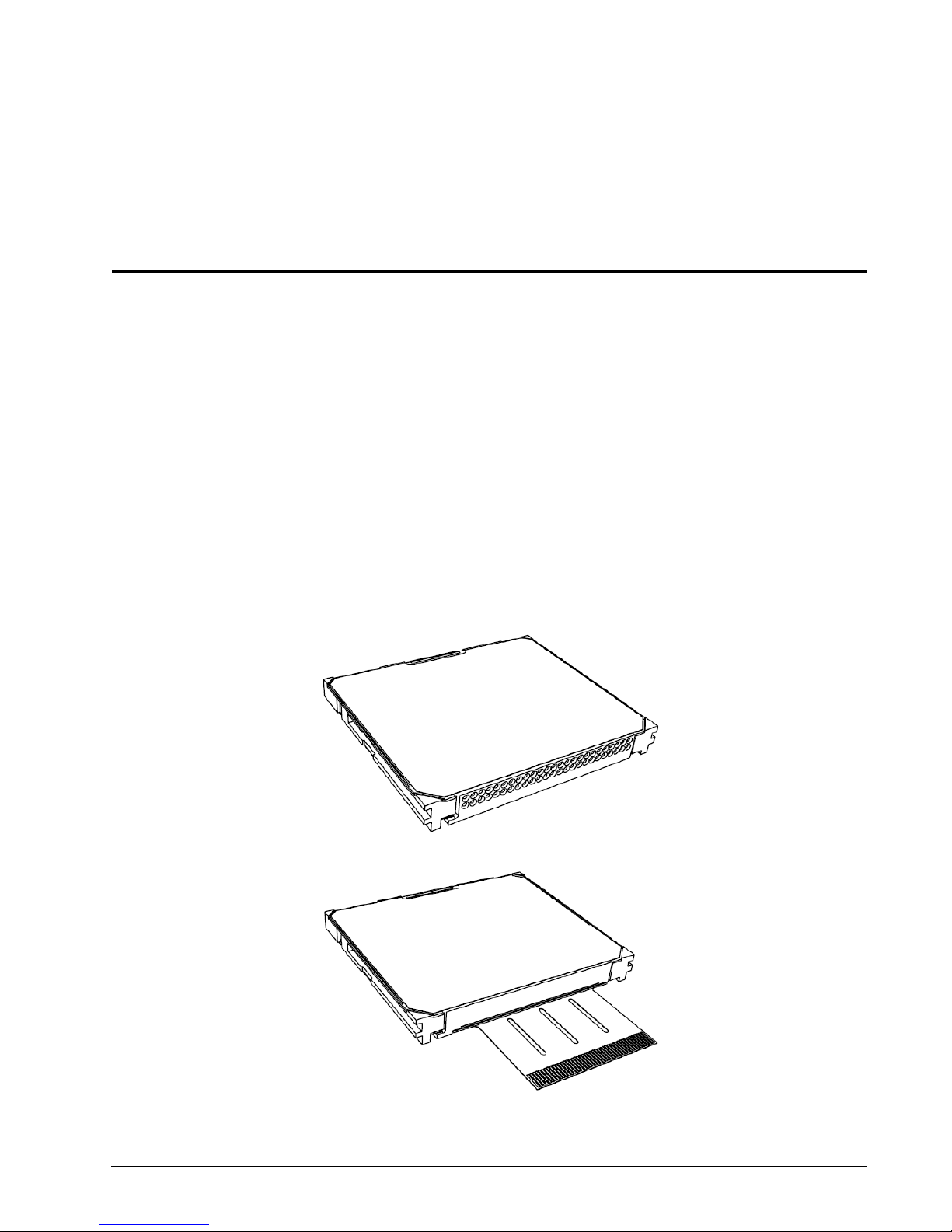
Figure 1. ST1 Series CompactFlash+ disc drive . . . . . . . . . . . . . . . . . . . . . . . . . . . . . . . . . . . . . . . . . . . 1
Figure 2. ST1 Series Flex (IDE interface) disc drive . . . . . . . . . . . . . . . . . . . . . . . . . . . . . . . . . . . . . . . . 1
Figure 3. Typical 3.3V startup and operation current profile . . . . . . . . . . . . . . . . . . . . . . . . . . . . . . . . . . 9
Figure 4. Location where tri-axial accelerometer will be placed on S1 drive. . . . . . . . . . . . . . . . . . . . . 13
Figure 5. Drive axis definition for S1 drives. . . . . . . . . . . . . . . . . . . . . . . . . . . . . . . . . . . . . . . . . . . . . . 13
Figure 6. CF model mechanical dimensions—top, side and end view . . . . . . . . . . . . . . . . . . . . . . . . . 22
Figure 7. FX Model mechanical dimensions—top, side and end view. . . . . . . . . . . . . . . . . . . . . . . . . . 23
ST1 Series Product Manual, Rev. A vii

viii ST1 Series Product Manual, Rev. A
1.0 Introduction
This manual describes the functional, mechanical and interface specifications for the following Seagate® ST1
®
Series drives:
• ST650211CF and ST625211CF CompactFlash+ Type II disc drives.
• ST650211FX and ST625211FX Flex (IDE interface) disc drives.
These drives provide the following key features:
• 3,600-RPM spindle speed and 2-Mbyte buffer combine for superior performance.
• Quiet operation. Fluid Dynamic Bearing (FDB) motor.
• Giant magnetoresistive (GMR) recording heads and EPRML technology, which provide the drives with
increased areal density.
• State-of-the-art cache and on-the-fly error-correction algorithms.
• 1.5K Gs nonoperating shock, and 200 Gs operating shock.
• SeaTools™ diagnostic software performs a drive self-test that eliminates unnecessary drive returns.
• The 3D Defense System™, which includes Drive Defense, Data Defense, and Diagnostic Defense, offers the
industry’s most comprehensive protection for disc drives
.
Figure 1. ST1 Series CompactFlash+ disc drive
Figure 2. ST1 Series Flex (IDE interface) disc drive
ST1 Series Product Manual, Rev. A 1

1.1 Disclaimer
Seagate Technology LLC makes no warranties whatsoever, including any warranty of merchantability, non
infringement, fitness for any particular purpose, or any warranty otherwise arising out of any proposal, specifi
cation or sample. Seagate may not be held liable for any direct, indirect, incidental, special, exemplary, or consequential damages (including, but not limited to, loss of use, data, or profits; procurement of substitute goods
or services; or business interruptions) however caused and on any theory of liability, whether in contract, strict
liability, or tort (including negligence or otherwise) arising in any way from the use of this kit, even if advised of
the possibility of such damage.
1.2 Drive care
Do not use the ST1 Series disc drives outside of the ranges of environmental conditions found in Section 2.10,
"Environmental specifications." Doing so may void the warranty of the ST1 Series disc drive.
1.3 Handling precautions
• Do not cover or seal the breather hole! Covering or sealing the breather hole may result in loss of data.
• Do not press on the drive! Do not apply any force to the drive during handling or installation.
• Always handle the drive with care to prevent damage from shock, vibration, or electrostatic discharge (ESD).
• Handle the drive carefully by the edges. Do not touch any exposed printed circuit board or the top cover.
• Do not write on the label or remove it. Do not apply additional labels.
• Always carry the drive in its plastic case.
• Do not drop the drive.
• Do not expose the drive to wet conditions.
• Do not place the drive near a strong magnetic field.
• Do not expose the drive to extreme temperatures.
• Do not use the drive in CF+TM Type II slots without an ejection mechanism.
• The drive may become hot during operation. Be careful when removing the drive from the host device
immediately after operation.
-
2 ST1 Series Product Manual, Rev. A
2.0 Drive specifications
Unless otherwise noted, all specifications are measured under ambient conditions, at 25°C, and nominal
power. For convenience, the phrases the drive and this drive are used throughout this manual to indicate
ST650211CF, ST650211FX, ST625211FX, and ST625211CF model drives.
2.1 Power, access times and acoustics
The specifications listed in this table are for quick reference. For details on specification measurement or definition, see the appropriate section of this manual.
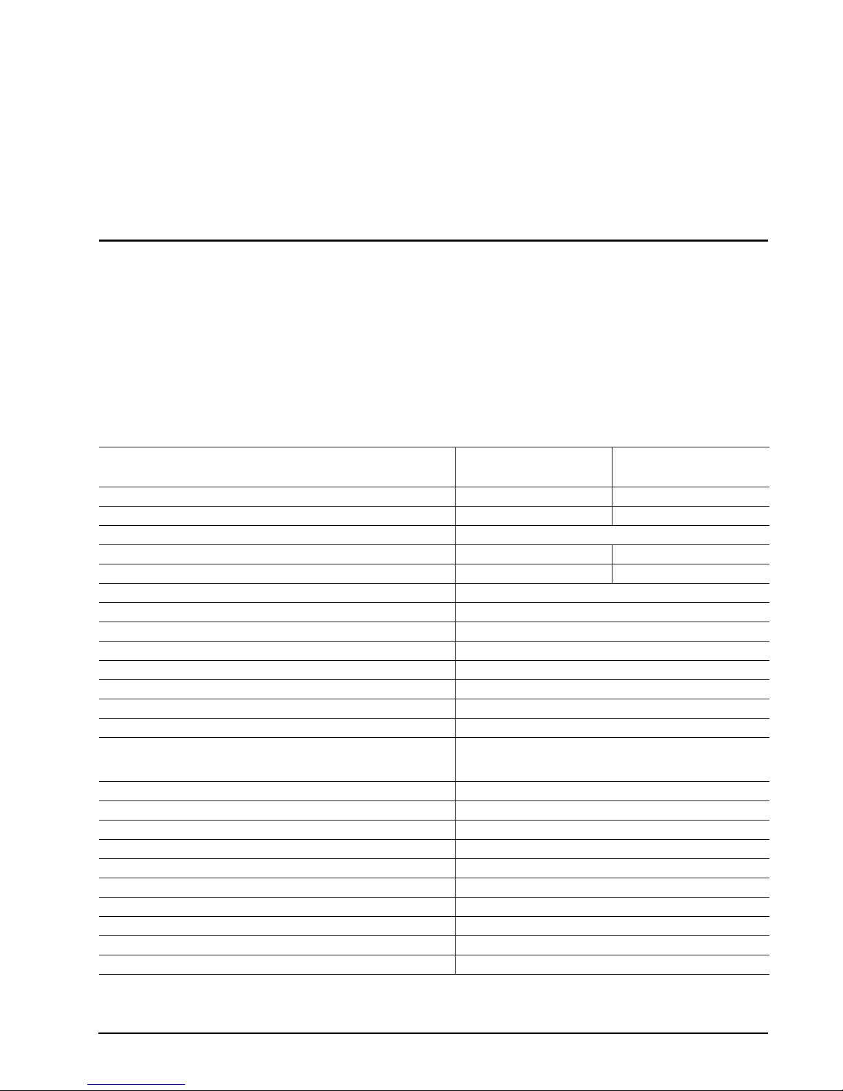
Table 1: Specifications
ST650211CF
Drive specification
Formatted Gbytes (512 bytes/sector) 5.0 2.5
Guaranteed sectors 9,767,520 4,883,760
Bytes per sector 512
Physical read/write heads 2 1
Discs 1 1
Cache (Mbytes) 2
Recording density, BPI (bits/inch max) 651,000
Track density. TPI (tracks/inch max) 105,000
Areal density (Gbits/inch2 max) 68.3
Spindle speed (RPM) 3,600
Internal data transfer rate OD (Mbytes/sec max) 9.67
Sustained data transfer rate OD (Mbytes/sec) 7.0
I/O data-transfer rate (Mbytes/sec max) 33.3MB/s (UDMA 2)
ATA data-transfer modes supported PIO modes 0–4;
Height 5.0 max (0.1968 inches max)
Width 42.80 +/-0.101 mm (1.685 +/-0.004 inches)
Length 36.40 +/-0.15 mm (1.433 +/-0.006 inches)
Weight (typical) 19 grams (0.041 lb.)
Average latency (msec) 8.3
Power-on to ready (sec typical / max) 2.0 / 2.5
Standby to ready (sec typical / max) 2.0 / 2.5
Startup current 5V (peak) (maximum RMS in 10ms window) 300 mA
Track-to-track average seek time (msec typical, read) 2.0
Average seek time (msec typical, read) 2.0
ST650211FX
Multiword DMA modes 0-2;
Ultra DMA modes 0–2
ST625211CF
ST625211FX
ST1 Series Product Manual, Rev. A 3
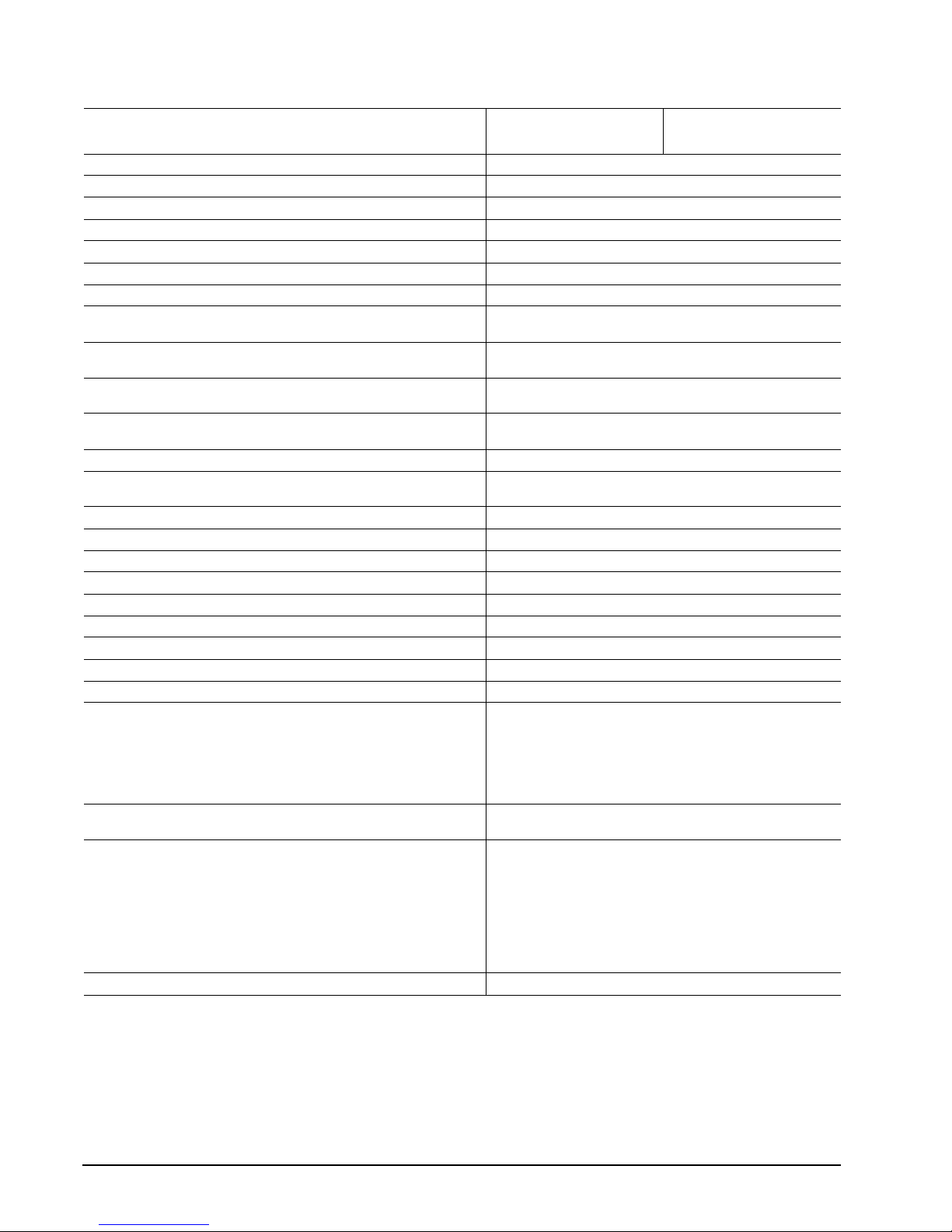
Table 1: Specifications
ST650211CF
Drive specification
Average seek, read (msec typical/max) 16.0/17.0
Full-stroke seek (msec typical/max) 26.0/27.0
Seek power (typical 3.3V) 226 mA
Read/write power (typical 3.3V) 300/310 mA
Performance idle mode (typical 3.3V) 200 mA
Low power idle mode (typical 3.3V) 90 mA
Standby/Sleep mode (typical) 30 mA
Voltage tolerance (including noise) 3.3V ± 5%
Ambient temperature 0° to 70°C (operating) (70°C case temperature)
Temperature gradient (°C per hour max) 20°C (operating)
Relative humidity (noncondensing) 5% to 90% (operating)
Relative humidity gradient 30% per hour max
Wet bulb temperature (°C max) 33°C (operating)
Altitude, operating –60.98 m to 3,048 m (–200 ft to 10,000+ ft)
Altitude, nonoperating (below mean sea level, max) –60.98 m to 12,192 m (–200 ft to 40,000+ ft)
Shock, operating (Gs max at1 msec) Read 200
Shock, operating (Gs max at 2 msec) Write 175
Shock, operating (Gs max at 2 msec) Write 175
Shock, nonoperating (Gs max at 1 msec) 1500
Shock, nonoperating (Gs max at 0.5 msec) 1500
Vibration, operating (max displacement may apply below 10 hz) 1.0 Gs (0 to peak, 5–500 Hz) @ 2 oct/min sweep rate
Vibration, nonoperating (max displacement may apply below 22 hz) 5.0 Gs (0 to peak, 5–500 Hz) @ 0.5 oct/min sweep rate
Drive acoustics, sound power (bels)
Idle (typical / max) 2.1/ 2.4
Operational (typical / max) 2.2 / 2.5
Nonrecoverable read errors
Mean time between failures (power-on hours) 100,000 at 40°C
Load/Unload (LUL) cycles
25°C, 50% relative humidity
32°C, 80% relative humidity
5°C, 80% relative humidity
5°C, 10% relative humidity
55°C, 16% relative humidity
Warranty Per agreement
ST650211FX
5V ± 10%
–40° to 70°C (nonoperating)
30°C (nonoperating)
5% to 95% (nonoperating)
40°C (nonoperating)
1 per 1014 bits read
Max case temperature: 70°C
300,000 software-controlled power on/off cycles
20,000 hard power on/off cycles
200,000 software-controlled power on/off cycles
20,000 hard power on/off cycles
ST625211CF
ST625211FX
4 ST1 Series Product Manual, Rev. A

2.2 Formatted capacity
Model Formatted capacity Guaranteed sectors Bytes per sector
ST650211CF
ST650211FX
ST625211CF
ST625211FX
5 Gbytes 9,767,520 512
2.5 Gbytes 4,883,760 512
2.3 Default logical geometry
Model Cylinders Read/write heads Sectors per track
ST650211CF
ST650211FX
ST625211CF
ST625211FX
9690 16 63
4845 16 63
LBA mode
When addressing these drives in LBA mode, all blocks (sectors) are consecutively numbered from 0 to n–1,
where n is the number of guaranteed sectors as defined above.
2.4 Physical organization
Model Read/write heads Number of discs
ST650211CF
ST650211FX
2 1
ST625211CF
ST625211FX
1 1
ST1 Series Product Manual, Rev. A 5

2.5 Recording and interface technology
Technology Specification
Interface CompactFlash 2.0 (CF+ 2.0)
Recording method RLL 0,20
Recording density BPI (bits/inch max) 651,000
Track density TPI (tracks/inch max) 105,000
Areal density (Gbits/inch2 max) 68.3
Spindle speed (RPM) (± 0.2%) 3,600
Internal data-transfer rate OD (Mbits/sec max) 9.67
Sustained data transfer rate OD (Mbytes/sec max) 7.0
I/O data-transfer rate (Mbytes/sec max) 33.3MB/s (UDMA 2)
Interleave 1:1
Cache buffer
ST650211CF, ST650211FX,
ST625211CF and ST625211FX
2.6 Physical characteristics
Height (mm)
(inches)
Width (mm)
(inches)
Length (mm)
(inches)
Typical weight (grams)
(pounds)
Interface Connector
ST650211CF, ST625211CF
ST650211FX, ST625211FX
5.0 +/-0.1 mm
0.1968 +/-0.004 inches
42.80 +/-0.101
1.685 +/-0.004
36.40 +/-0.15
1.433 +/-0.006
19
0.041
CompactFlash Type II Connector (50-pin)
Seagate Flex Connector (45-way)
2 Mbytes (2,048 kbytes)
6 ST1 Series Product Manual, Rev. A
2.7 Seek time
Seek measurements are taken with nominal power at 25°C ambient temperature. All times are measured using
drive diagnostics. The specifications below are defined as follows:
• Track-to-track seek time is an average of all possible single-track seeks in both directions.
• Average seek time is a true statistical random average of at least 5,000 measurements of seeks between
random tracks, less overhead.
*Seek times (msec) Read Write
Typical Max Typical Max
Track-to-track 2.0 2.5 3.0 3.5
Average 16.0 17.0 19.0 22.0
Full-stroke 26.0 27.0 29.0 32.0
Average latency 8.3
*Measured in performance mode
Note. These drives are designed to consistently meet the seek times represented in this manual. Physical seeks,
regardless of mode (such as track-to-track and average), are expected to meet or exceed the noted values.
However, due to the manner in which these drives are formatted, benchmark tests that include command
overhead or measure logical seeks may produce results that vary from these specifications.
2.8 Time to ready
Time to ready Typical Max
Power-on to Ready (sec) 2.0 2.5
Standby to Ready (sec) 2.0 2.5
ST1 Series Product Manual, Rev. A 7

2.9 Power specifications
The drive receives DC power (+3.3V or +5V) through the CompactFlash interface connector for ST650211CF
and ST625211CF models, and (+3.3V only) through the Flex interface connector for ST650211FX and
ST625211FX models.
2.9.1 Power consumption
Power requirements for the drives are listed in the table on page 9. Typical power measurements are based on
an average of drives tested, under nominal conditions, using +3.3V and +5.0V input voltage at 25°C ambient
temperature.
• Spinup power
Spinup power is measured from the time of power-on to the time that the drive spindle reaches operating speed.
• Seek mode
During seek mode, the read/write actuator arm moves toward a specific position on the disc surface and does
not execute a read or write operation. Servo electronics are active. Seek mode power is measured based on
three random seek operations every 100 msecs. This mode is not typical.
• Read/write power and current
Read/write power is measured with the heads on track, at the moment while the head is writing/reading
from/to disc. It is performed with 100% duty cycle of write/read operation.
• Idle mode power, low
Spindle motor is working normally with actuator unloaded to the parked position.
• Standby mode / Sleep mode
During Standby mode, the drive accepts commands, but the drive is not spinning, and the servo and read/
write electronics are in power-down mode.
8 ST1 Series Product Manual, Rev. A
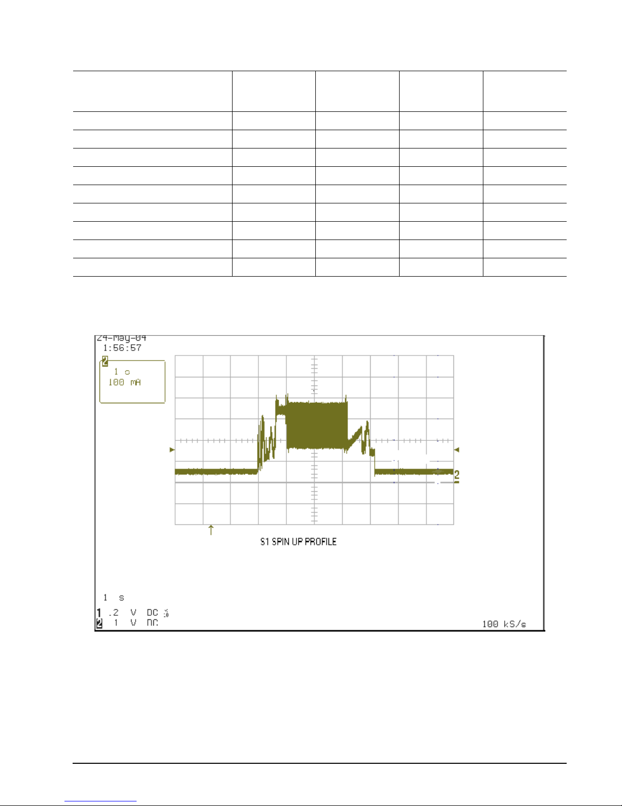
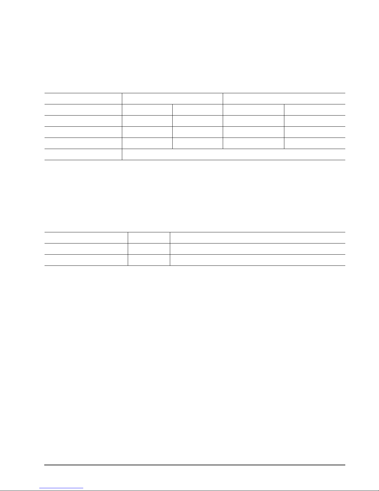
Table 2: DC power
ST1 Power Consumption (W)
Max current the average of the
peak value in 10ms window
Average
3.3V
Max
3.3V
Average
5.0V
Max
5.0V
Current 330 330
Spinup 300 300
Load/Unload current 300 300
Write 310 330 310 330
Read 310 330 320 340
Seek 226 300 226 300
Performance idle 200 205
Low power idle 90 92
Standby/Sleep 30 33
*During periods of drive idle, some offline activity may occur according to the S.M.A.R.T. specification, which may increase acoustic and
power to operational levels.
2.9.1.1 Typical current profile
Figure 3. Typical 3.3V startup and operation current profile
ST1 Series Product Manual, Rev. A 9

2.9.2 Conducted noise
Input noise ripple is measured at the host system power supply across an equivalent 15-ohm resistive load on
the +5 volt line.
Using 5-volt power, the drive is expected to operate with a maximum of 100 mV peak-to-peak square-wave
injected noise at up to 20 MHz.
Using 3.3-volt power, the drive is expected to operate with a maximum of 70 mV peak-to-peak square-wave
injected noise at up to 20 MHz.
Note. Equivalent resistance is calculated by dividing the nominal voltage by the typical RMS read/write
current.
2.9.3 Voltage tolerance
Voltage tolerance (including noise):
5.0V ± 10%
3.3V ± 5%
10 ST1 Series Product Manual, Rev. A

2.9.4 Power-management modes
The drive provides programmable power management to provide greater energy efficiency. The drive features
the following power-management modes:
Table 3: Power management modes
Power modes Heads Spindle Buffer
Active (operating) Tracking Rotating Enabled
Idle, low power Parked Rotating Disabled
Standby/Sleep Parked Stopped Disabled
• Active mode
The drive is in Active mode during the read/write and seek operations.
• Low power idle mode
Drive enters Low Power Idle mode from Active Idle mode when the Advanced Power Management Level is
set above 80h and the Idle timer is reached at 2 seconds. Disc is spinning and head is parked and drive accepts
all commands and returns to Active mode any time disc access is necessary.
• Performance idle mode
The buffer remains enabled, and the drive accepts all commands and returns to Active mode any time disc
access is necessary.
• Standby/Sleep mode
The drive enters Standby mode when the host sends a Standby Immediate command. If the host has set the
standby timer, the drive can also enter Standby mode automatically after the drive has been inactive for a
specifiable length of time. The standby timer delay is established using a Standby or Idle command. In Standby
mode, the drive buffer is enabled, the heads are parked and the spindle is at rest. The drive accepts all
commands and returns to Active mode any time disc access is necessary.
• Standby timers
Each time the drive performs an Active function (such as read, write or seek), the standby timer is reinitialized
and begins counting down from its specified delay times to zero. If the standby timer reaches zero before any
drive activity is required, the drive makes a transition to Standby mode. In both Idle and Standby mode, the
drive accepts all commands and returns to Active mode when disc access is necessary.
ST1 Series Product Manual, Rev. A 11
 Loading...