

Page 1

. . . . . . . . . . . . . . . . . . . . . . . . . . . . . . . . . . . . .. . . . .
Decathlon Family
. . . . . . . . . . . . . . . . . . . . . . . . . . . . . . . . . . . . .. . . . .
ST5660N, ST5660NC
. . . . . . . . . . . . . . . . . . . . . . . . . . . . . . . . . . . . .. . . . .
SCSI Interface Drives
. . . . . . . . . . . . . . . . . . . . . . . . . . . . . . . . . . . . .. . . . .
. . . . . . . . . . . . . . . . . . . . . . . . . . . . . . . . . . . . .. . . . .
Product Manual
. . . . . . . . . . . . . . . . . . . . . . . . . . . . . . . . . . . . .. . . . .
Page 2

Page 3
. . . . . . . . . . . . . . . . . . . . . . . . . . . . . . . . . . . . .. . . . .
Decathlon Family
. . . . . . . . . . . . . . . . . . . . . . . . . . . . . . . . . . . . .. . . . .
ST5660N, ST5660NC
. . . . . . . . . . . . . . . . . . . . . . . . . . . . . . . . . . . . .. . . . .
SCSI Interface Drives
. . . . . . . . . . . . . . . . . . . . . . . . . . . . . . . . . . . . .. . . . .
. . . . . . . . . . . . . . . . . . . . . . . . . . . . . . . . . . . . .. . . . .
Product Manual
. . . . . . . . . . . . . . . . . . . . . . . . . . . . . . . . . . . . .. . . . .
Page 4

© 1994 Seagate Technology, Inc. All rights reserved
Publication Number: 36245-004, Rev. B
September 1994
®
Seagate
, Seagate Technology® and the Seagate logo are registered
trademarks of Seagate Technology, Inc. Other product names are trademarks or registered trademarks of their owners.
Seagate reserves the right to change, without notice, product offerings
or specifications. No part of this publication may be reproduced in any
form without written permission from Seagate Technology, Inc.
Page 5

Decathlon Family Product Manual, Rev. B iii
Contents
1.0 Specifications summary . . . . . . . . . . . . . . . . . . . . 1
1.1 Formatted capacity . . . . . . . . . . . . . . . . . . . . . . 1
1.2 Physical geometry . . . . . . . . . . . . . . . . . . . . . . . 1
1.3 Functional specifications . . . . . . . . . . . . . . . . . . . 1
1.4 Physical dimens ions . . . . . . . . . . . . . . . . . . . . . . 2
1.5 Reliability . . . . . . . . . . . . . . . . . . . . . . . . . . . 2
1.6 Acoustics . . . . . . . . . . . . . . . . . . . . . . . . . . . 2
1.7 Seek time . . . . . . . . . . . . . . . . . . . . . . . . . . . 2
1.7.1 Read look-ahead and caching . . . . . . . . . . . . . . 3
1.8 Environmental . . . . . . . . . . . . . . . . . . . . . . . . . 3
1.8.1 Ambient temperature . . . . . . . . . . . . . . . . . . . 3
1.8.2 Temperature gradient . . . . . . . . . . . . . . . . . . . 3
1.8.3 Relative humidity . . . . . . . . . . . . . . . . . . . . . 3
1.8.4 Altitude . . . . . . . . . . . . . . . . . . . . . . . . . . 4
1.9 Shock and vibration . . . . . . . . . . . . . . . . . . . . . . 4
1.10 Start and stop time . . . . . . . . . . . . . . . . . . . . . . 4
1.10.1 Power-up sequence . . . . . . . . . . . . . . . . . . . 5
1.10.2 Power-down sequence . . . . . . . . . . . . . . . . . 5
1.10.3 Auto-park . . . . . . . . . . . . . . . . . . . . . . . . 6
1.11 DC power . . . . . . . . . . . . . . . . . . . . . . . . . . . 6
1.11.1 Input noise . . . . . . . . . . . . . . . . . . . . . . . . 6
1.12 Power management . . . . . . . . . . . . . . . . . . . . . 6
1.12.1 Power consumption . . . . . . . . . . . . . . . . . . . 7
1.13 Agency listings . . . . . . . . . . . . . . . . . . . . . . . . 9
1.14 FCC verification . . . . . . . . . . . . . . . . . . . . . . . 9
2.0 Hardware and interface . . . . . . . . . . . . . . . . . . . . 11
2.1 SCSI-2 compatibility . . . . . . . . . . . . . . . . . . . . . 11
2.2 Handling and static-discharge precautions . . . . . . . . . 11
2.3 Electrical interface . . . . . . . . . . . . . . . . . . . . . . 12
Page 6

iv Decathlon Family Product Manual, Rev. B
2.4 Interface and connector configuration . . . . . . . . . . . . 13
2.4.1 ST5660N interface connector . . . . . . . . . . . . . 13
2.4.2 ST5660N interface connector pin assignments . . . . 15
2.4.3 ST5660NC interface connector . . . . . . . . . . . . . 16
2.4.4 ST5660NC interface connector pin assignments . . . . 16
2.5 Interface cable requirements . . . . . . . . . . . . . . . . 18
2.5.1 Interface cable length for asynchronous operation . . . 19
2.5.2 Interface cable for Fast SCSI operation . . . . . . . . 19
2.6 Options jumper block . . . . . . . . . . . . . . . . . . . . 19
2.6.1 Active Termination . . . . . . . . . . . . . . . . . . . 20
2.6.2 SCSI address . . . . . . . . . . . . . . . . . . . . . . 20
2.6.3 Terminator power source selection . . . . . . . . . . . 20
2.6.4 Parity enable option . . . . . . . . . . . . . . . . . . 22
2.6.5 Start/stop option . . . . . . . . . . . . . . . . . . . . 22
2.6.6 Remote LED connection . . . . . . . . . . . . . . . . 22
2.7 Auxiliary SCSI ID block . . . . . . . . . . . . . . . . . . . 22
2.8 Daisy chaining . . . . . . . . . . . . . . . . . . . . . . . . 22
2.9 Hot-plugging . . . . . . . . . . . . . . . . . . . . . . . . . 24
2.10 Mounting the drive . . . . . . . . . . . . . . . . . . . . . 24
3.0 Command set . . . . . . . . . . . . . . . . . . . . . . . . . 27
3.1 Command descriptor block . . . . . . . . . . . . . . . . . 27
3.2 Status byte codes . . . . . . . . . . . . . . . . . . . . . . 27
3.3 Supported commands . . . . . . . . . . . . . . . . . . . . 29
3.4 Group 0 commands . . . . . . . . . . . . . . . . . . . . . 30
3.4.1 Test Unit Ready command (00
3.4.2 Rezero Unit command (01
3.4.3 Request Sense command (03
3.4.4 Format Unit command (04
3.4.5 Reassign Blocks command (07
3.4.6 Read command (08
3.4.7 Write command (0A
) . . . . . . . . . . . . . . . . . 39
H
) . . . . . . . . . . . . . . . . . 40
H
) . . . . . . . . . . . . 30
H
) . . . . . . . . . . . . . . 30
H
) . . . . . . . . . . . . 31
H
) . . . . . . . . . . . . . . 32
H
) . . . . . . . . . . . 37
H
Page 7

Decathlon Family Product Manual, Rev. B v
3.4.8 Seek command (0BH) . . . . . . . . . . . . . . . . . 41
3.4.9 Inquiry command (12
3.4.10 Mode Select command (15
3.4.11 Reserve command (16
3.4.12 Release command (17
3.4.13 Mode Sense command (1A
3.4.14 Start/Stop Unit command (1B
3.4.15 Receive Diagnost ic Results command (1C
3.4.16 Send Diagnost ic command (1D
) . . . . . . . . . . . . . . . . . 41
H
) . . . . . . . . . . . . . 42
H
) . . . . . . . . . . . . . . . 46
H
) . . . . . . . . . . . . . . . 47
H
) . . . . . . . . . . . . . 48
H
) . . . . . . . . . . . . 52
H
) . . . . . 53
H
) . . . . . . . . . . . 55
H
3.5 Group 1 commands . . . . . . . . . . . . . . . . . . . . . 56
3.5.1 Read Capacity command (25
3.5.2 Read Extended command (28
3.5.3 Write Extended command (2A
3.5.4 Seek Extended command (2B
3.5.5 Write and Verify command (2E
3.5.6 Verify command (2F
) . . . . . . . . . . . . . . . . . 62
H
3.5.7 Read Defect Data command (37
3.5.8 Write Data Buffer command (3B
3.5.9 Read Data Buffer command (3C
3.5.10 Read Long command (3E
3.5.11 Write Long command (3F
) . . . . . . . . . . . . 56
H
) . . . . . . . . . . . . 57
H
) . . . . . . . . . . . . 58
H
) . . . . . . . . . . . . 60
H
) . . . . . . . . . . . . 60
H
) . . . . . . . . . . . 63
H
) . . . . . . . . . . . 65
H
) . . . . . . . . . . . 66
H
) . . . . . . . . . . . . . . 68
H
) . . . . . . . . . . . . . . 69
H
3.6 Group 2, 3 and 4 commands . . . . . . . . . . . . . . . . 70
3.7 Group 5 and 6 commands . . . . . . . . . . . . . . . . . 70
3.8 Group 7 commands . . . . . . . . . . . . . . . . . . . . . 70
Appendix A. Supported messages . . . . . . . . . . . . . . . . 71
A.1 Single-byte messages . . . . . . . . . . . . . . . . . . . . 71
A.2 Synchronous data transfer request message (01
) . . . . . 72
H
Appendix B. Sense data . . . . . . . . . . . . . . . . . . . . . . 73
B.1 Additional sense data . . . . . . . . . . . . . . . . . . . . 73
B.2 Sense key . . . . . . . . . . . . . . . . . . . . . . . . . . 74
B.3 Additional sense code and additional sense code qualifier . 76
Page 8

vi Decathlon Family Product Manual, Rev. B
Appendix C. Mode pages . . . . . . . . . . . . . . . . . . . . . 81
A.1 Error Recovery page (01
A.2 Disconnect/Reconnect page (02
A.3 Format Device page (03
A.4 Rigid Disc Geometry page (04
A.5 Caching page (08
H
) . . . . . . . . . . . . . . . . . 83
H
) . . . . . . . . . . . . . 85
H
) . . . . . . . . . . . . . . . . . 87
H
) . . . . . . . . . . . . . . 90
H
) . . . . . . . . . . . . . . . . . . . . . 91
A.5.1 Read look-ahead and read caching . . . . . . . . . . 91
A.5.2 Write caching and write merging . . . . . . . . . . . . 92
A.5.3 Caching page description . . . . . . . . . . . . . . . 93
A.6 Control Mode page (0A
A.7 Notch page (0C
) . . . . . . . . . . . . . . . . . . . . . . 98
H
A.8 Cache Control page (38
A.9 Soft ID page (Flash memory) (3C
A.10 Operating page (Flash memory) (00
) . . . . . . . . . . . . . . . . . . 96
H
) . . . . . . . . . . . . . . . . . 100
H
) . . . . . . . . . . . . 101
H
) . . . . . . . . . . 102
H
Appendix D. Inquiry data . . . . . . . . . . . . . . . . . . . . 105
D.1 Inquiry data . . . . . . . . . . . . . . . . . . . . . . . . 105
D.2 Vital product data pages . . . . . . . . . . . . . . . . . 108
D.2.1 Unit Serial Number page (80
D.2.2 Implemented Operating Definition page (81
D.2.3 Firmware Numbers page (C0
D.2.4 Date Code page (C1
) . . . . . . . . . . . . . . . . 111
H
D.2.5 Jumper Settings page (C2
) . . . . . . . . . . . . 109
H
) . . . . 109
H
) . . . . . . . . . . . 110
H
) . . . . . . . . . . . . . 111
H
Appendix E. Timing diagrams . . . . . . . . . . . . . . . . . . 113
Page 9

Decathlon Family Product Manual, Rev. B vii
Figures
Figure 1.Typical startup current profile . . . . . . . . . . . . . . . . 8
Figure 2. Singled-ended transmitter and receiver . . . . . . . . . . 12
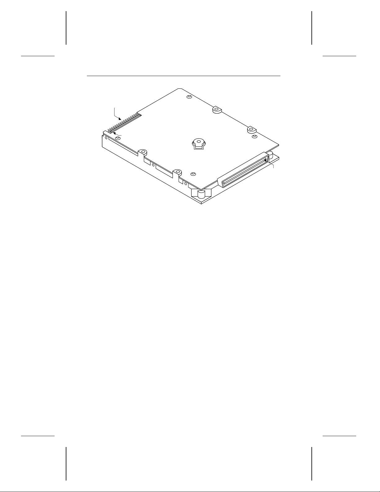
Figure 3. ST5660N connectors . . . . . . . . . . . . . . . . . . . 14
Figure 4. ST5660NC connectors . . . . . . . . . . . . . . . . . . 18
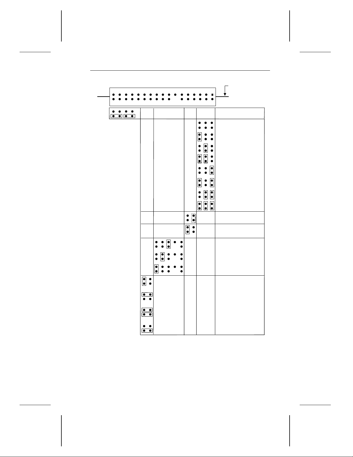
Figure 5. Options jumper block (J8) settings . . . . . . . . . . . . 21
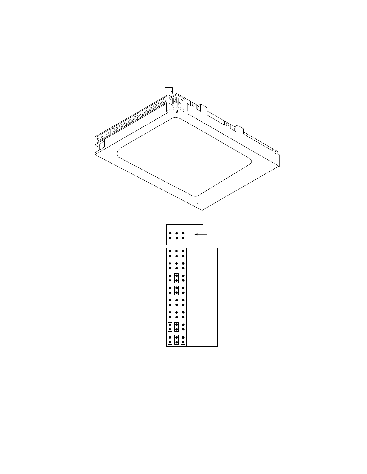
Figure 6. ST5660N auxiliary SCSI ID jumper block (J5) settings . . 23
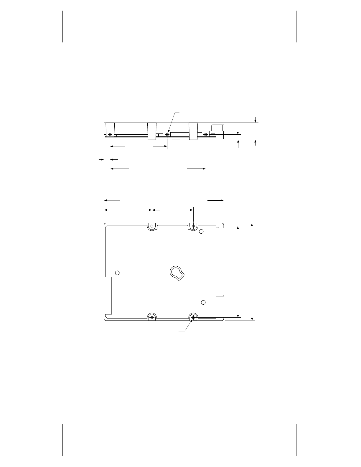
Figure 7. ST5660N mounting dimensions . . . . . . . . . . . . . . 25
Figure 8. ST5660NC mounting dimensions . . . . . . . . . . . . . 26
Figure 9. Arbitration, selection (without ATN) and command . . . 113
Figure 10. Arbitration, selection (with ATN) and message out . . 114
Figure 11. Identify message out to command . . . . . . . . . . . 115
Figure 12. Command descriptor block transfer . . . . . . . . . . 116
Figure 13. Command, status, command complete message and
bus free . . . . . . . . . . . . . . . . . . . . . . . . 117
Figure 14. Last command byte, disconnect message, bus free
and reselection . . . . . . . . . . . . . . . . . . . . 118
Figure 15. Arbitration, reselection and message in . . . . . . . . 119
Figure 16. Reselection, status, command complete and bus free 120
Figure 17. Last command byte to data in . . . . . . . . . . . . . 121
Figure 18. Last command byte to data out . . . . . . . . . . . . 122
Figure 19. Reselect identify message to data in . . . . . . . . . 123
Figure 20. Data in block transfer . . . . . . . . . . . . . . . . . 124
Figure 21. Data out block transfer . . . . . . . . . . . . . . . . . 125
Figure 22. Last data byte, save pointer message and disconnect
message . . . . . . . . . . . . . . . . . . . . . . . . 126
Figure 23. Data in, status, command complete message and bus
free . . . . . . . . . . . . . . . . . . . . . . . . . . . 127
Figure 24. Synchronous timing . . . . . . . . . . . . . . . . . . 128
Figure 25. Synchronous write timing . . . . . . . . . . . . . . . 129
Page 10

1 Decathlon Family Product Manual, Rev. B
1.0 Specifications summary
1.1 Formatted capacity
The capacities specified here do not include spare sectors and cylinders.
The media contains one spare sector per track and two spare cylinders
per drive.
Formatted capacity (Mbytes*) 545.29
Total sectors 1,065,036
* One Mbyte equals one million bytes.
1.2 Physical geometry
Discs 2
Read/write heads 4
Cylinders 3,002
1.3 Functional specifications
Interface Fast SCSI-2
Zone Bit Recording method RLL (1,7)
External data transfer rate
(Mbytes per sec, avg)
Internal data transfer rate
(Mbits per sec)
Spindle speed (RPM) 4,500 ± 0.5%
Bytes per sector 512
Track density (TPI) 3,309
Recording density
(BPI, max)
5.0 asynchronous
10.0 synchronous
27.6 to 47.2
52,602
Page 11

Decathlon Family Product Manual, Rev. B 2
1.4 Physical dimensions
Height (max) 0.748 inches (19 mm)
Width (max) 4.00 inches (102.1 mm)
Depth (max) 5.00 inches (127.0 mm)
Weight (max) 1.0 lb (0.45 Kg)
1.5 Reliability
Read error rates are measured with automatic retries and data correction
with ECC enabled and all flaws reallocated. MTBF is measured at
nominal power at sea level and 40°C ambient temperature.
13
Nonrecoverable read errors 1 per 10
Seek errors 1 per 10
MTBF 300,000 power-on hours
Service life 5 years
bits transferred
7
physical seeks
1.6 Acoustics
Sound pressure is measured at idle from 1 meter above the drive top
cover.
Sound pressure, typ 26 dBA
Sound pressure, max 29 dBA
1.7 Seek time
All seek time measurements are taken under nominal conditions of
temperature and voltage with the drive mounted horizontally. In the
following table:
Track-to-track
•
seeks in both directions.
•
Average/typical
least 5,000 measurements of seeks in both directions between random cylinders, less overhead.
•
Full-stroke
block address zero (LBA 0) to the maximum LBA and back to LBA 0.
seek time is the average of all possible single-track
seek time is a true statistical random average of at
seek time is one-half the time needed to seek from logical
Page 12

3 Decathlon Family Product Manual, Rev. B
Track-to-track
seek time
3.5 msec typ
4.0 msec max
Note. Host overhead varies between systems and cannot be specified.
Drive internal overhead is measured by issuing a no-motion seek.
Drive overhead is typically less than 1.0 msec.
Average/typical
seek time
12.0 msec read
14.0 msec write
Full-stroke
seek time
25.0 msec max 6.67 msec
Average
latency
1.7.1 Read look-ahead and caching
The drive uses algorithms that improve seek performance by storing data
in a buffer and processing it at a more convenient time. Three methods
are used: read look-ahead, read caching and write caching. These are
described in Appendix C.5.
1.8 Environmental
This section specifies acceptable environmental conditions for the drive.
The operating specifications assume that the drive is powered up. The
nonoperating specifications assume that the drive is packaged as it was
shipped from the factory.
1.8.1 Ambient temperature
Operating 5°C to 55°C (41°F to 131°F)
Nonoperating –40°C to 70°C (–40°F to 158°F)
1.8.2 Temperature gradient
Operating 20°C per hour (36°F per hour)
Nonoperating 30°C per hour (54°F per hour)
1.8.3 Relative humidity
Operating 8% to 80% noncondensing
Maximum wet bulb 26°C (79°F)
Operating gradient, max 10% per hour
Nonoperating 5% to 95% noncondensing
Maximum wet bulb 26°C (79°F)
Page 13

Decathlon Family Product Manual, Rev. B 4
1.8.4 Altitude
Operating –1,000 ft to 10,000 ft (–305 m to 3,048 m)
Nonoperating –1,000 ft to 40,000 ft (–305 m to 12,192 m)
1.9 Shock and vibration
All shock and vibration specifications assume that the inputs are measured
at the drive mounting screws. Shock measurements are based on an
11-msec, half sine wave shock pulse, not to be repeated more than twice
per second.
During normal operating shock and vibration, there is no physical damage to the drive or performance degradation.
During abnormal operating shock and vibration, there is no physical
damage to the drive, although performance may be degraded during the
shock or vibration episode. When normal operating shock levels resume,
the drive meets its performance specifications.
During nonoperating shock and vibration, the read/write heads are
positioned in the shipping zone.
Normal
operating
Shock 2 Gs 10 Gs 75 Gs
5–22 Hz vibration 0.020-inch
displacement
22–400 Hz vibration 0.50 Gs 0.75 Gs 4.00 Gs
Abnormal
operating Nonoperating
0.030-inch
displacement
0.160-inch
displacement
1.10 Start and stop time
If the motor start option is disabled, the drive becomes ready within
20 seconds after power is applied. If the motor start option is enabled,
the drive becomes ready within 20 seconds after it receives the Motor
Start command. If the drive receives a command to spin down or power
is removed, the drive stops within 15 seconds.
Page 14

5 Decathlon Family Product Manual, Rev. B
1.10.1 Power-up sequence
The following typical power-up sequence is provided to assist in evaluating drive performance. This information does not constitute a specification or a performance guarantee.
1. Power is applied to the disc drive.
2. The LED comes on for about 5 seconds.
3. Depending on whether there is a jumper installed on pins 15 and 16
of the options jumper block (J8) shown in Figure 5 on page 21, either
of the following sequences occurs:
a. If a jumper is not installed, the remote start option is not enabled,
and the drive begins to spin up as soon as power is applied.
b. If a jumper is installed, the remote start option is enabled and the
drive begins to spin up when the host commands the motor to start.
4. Within 250 msec after power is applied, the drive responds to the Test
Unit Ready, Request Sense, Mode Sense and Inquiry commands.
5. The drive begins to lock in speed-control circuits.
6. The actuator lock releases the actuator.
7. The spindle motor reaches operating speed in about 5 seconds. After
5 seconds, there are no speed variations.
8. The drive performs velocity adjustment seeks.
9. The drive seeks track 0 and becomes ready.
1.10.2 Power-down sequence
The following typical power-down sequence is provided to assist in
evaluating drive performance. This information does not constitute a
specification or a performance guarantee.
1. The power cable is unplugged from the drive, or the drive receives a
command to spin down.
2. Within 3 seconds after the motor begins to spin down, the actuator
lock engages, producing an audible sound.
3. The spindle stops within 15 seconds, whether the power cable is
unplugged from the drive or the drive receives the power-down
command.
Page 15

Decathlon Family Product Manual, Rev. B 6
1.10.3 Auto-park
Upon power-down, the read/write heads automatically move to the
shipping zone. The heads park inside the maximum data cylinder. When
power is applied, the heads recalibrate to track 0.
Caution. Do not move the drive until the spindle motor has come to a
complete stop; otherwise, you may damage the drive.
1.11 DC power
Except during the write procedure, you can apply power to the drive or
remove power from the drive, in any sequence, without losing data or
damaging the drive. If you remove power from the drive during the write
procedure, you may lose the data currently being written.
1.11.1 Input noise
+5V +12V
Voltage tolerance
(including noise)
Input noise frequency
(max)
Input noise
(max, peak-to-peak)
± 5% ± 5%
25 MHz 25 MHz
100 mV 240 mV
1.12 Power management
The drive supports power-management modes that reduce its overall
power consumption. The drive automatically changes from one mode to
another in response to interface activity. You do not need to change any
parameters or send any special commands to make the drive change
modes. The power-management modes are described below.
• Spinup. Spinup is defined as the period during which the spindle is
coming up to operating speed. The power consumed in this mode is
equivalent to the average power during the first 10 seconds after the
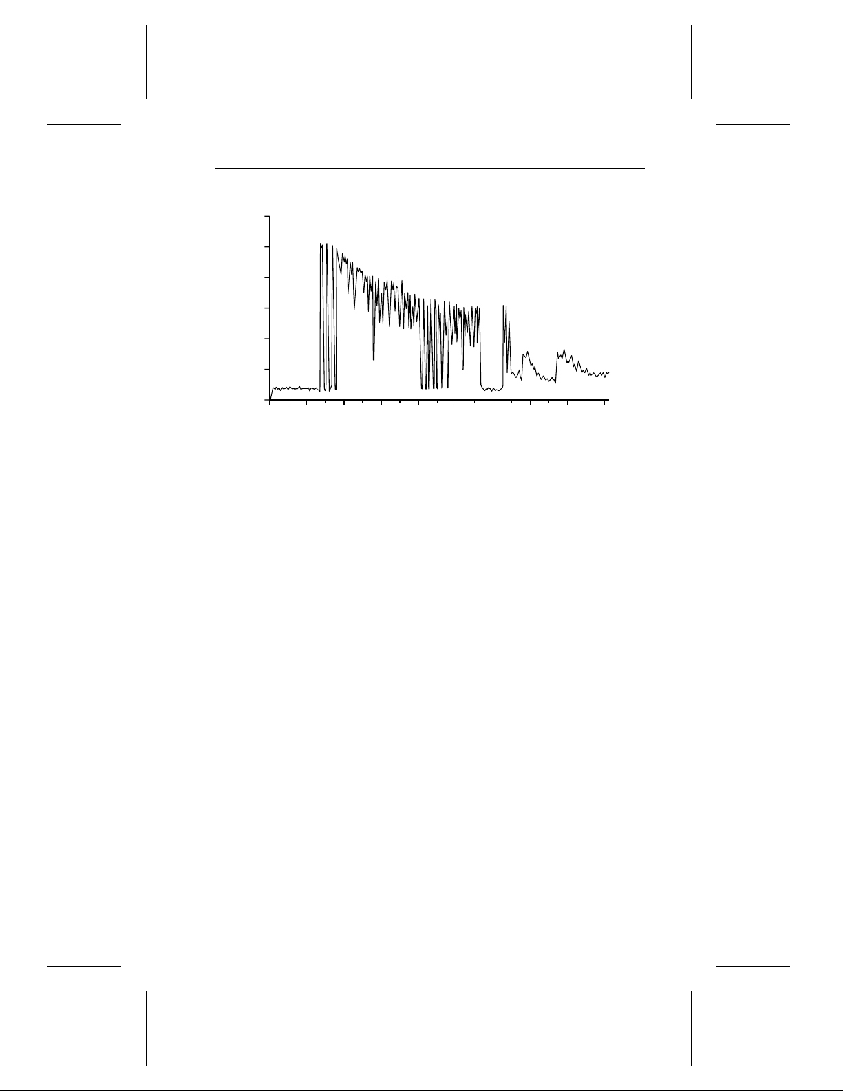
drive begins to spin up. Refer to the startup current chart in Figure 1
on page 8 for a typical representation of power consumption during
spinup.
Page 16

7 Decathlon Family Product Manual, Rev. B
• Seeking. The servo electronics are active and the heads are moving
to a specific location on the disc. The read/write electronics are
powered-down. The power consumed in this mode is equivalent to the
average power measured while executing random seeks with a 2revolution (26.6 msec) dwell between seeks. The drive enters this
mode from the Idle mode.
• Read/Write. The drive is reading or writing. All electronics are active
and the heads are on track. The drive enters this mode from the Idle
mode.
• Idle. The spindle is spinning, the heads are parked, and the servo and
read/write electronics are powered down. The drive is ready to accept
and execute any command after the heads recalibrate. The drive
enters this mode from the Read/Write mode.
• Standby. This mode is not implemented.
1.12.1 Power consumption
Values in the table below were measured at the drive power connector
with an RMS DC ammeter. The terminating resistor packs are removed
and terminator power is supplied through the SCSI connector. All values
are measured 10 minutes after the drive spins up except as noted.
During
Spinup
Current at +12V
Amps peak 1.25 — — —
RMS amps typ — 0.354 0.208 0.116
Watts typ — 4.25 2.50 1.394
Current at +5V
RMS amps typ — 0.35 0.40 0.221
Watts typ — 1.75 2.00 1.106
Power
Total watts typ — 6.00 4.50 2.50
Seeking
Read/
Write
Idle
Page 17
0
0
0.2
0.4
0.6
0.8
1.0
1.2
1
T1
T2
T3
T4 T5
T6
T7
2 3 4 5 6 7 8 9
Amps
Seconds
Decathlon Family Product Manual, Rev. B 8
Figure 1. Typical startup current profile
T1 Voltage is applied to the drive.
T2 After a delay, the startup current is applied and the spindle
begins to turn.
T3 The accelerating current is applied, causing the spindle speed
to increase.
T4 The spindle speed is close to the final, correct value. The drive
begins to lock in the speed-control circuits.
T5 The actuator lock releases the actuator.
T6 The final speed- control lock is achieved.
T7 The servo locks in on track 0 and the drive is ready.
Page 18

9 Decathlon Family Product Manual, Rev. B
1.13 Agency listings
This drive is listed by agencies as follows:
• Recognized in accordance with UL 478 and UL 1950
• Certified to CSA C22.2 No. 220-M1986 and CSA C22.2 No. 950
• Certified to VDE 0805/05.90 and EN 60950/1.88 as tested by VDE
1.14 FCC verification
Decathlon family drives are intended to be contained solely within a
personal computer or similar enclosure (not attached to an external
device). As such, a drive is considered to be a subassembly even when
individually marketed to the customer. As a subassembly, no Federal
Communications Commission authorization, verification or certification
of the device is required.
Seagate Technology, Inc. has tested these drives in an enclosure as
described above to ensure that the total assembly (enclosure, disc drive,
motherboard, power supply, etc.) does comply with the limits for a
Class B computing device, pursuant to Subpart J of Part 15 of the FCC
rules. Operation with noncertified assemblies is likely to result in interference to radio and television reception.
Radio and television interference. This equipment generates and uses
radio frequency energy and, if not installed and used in strict accordance
with the manufacturer’s instructions, may cause interference to radio and
television reception.
This equipment is designed to provide reasonable protection against
such interference in a residential installation. However, there is no
guarantee that interference will not occur in a particular installation. If this
equipment does cause interference to radio or television, which can be
determined by turning the equipment on and off, you are encouraged to
try one or more of the following corrective measures:
• Reorient the receiving antenna.
• Move the device to one side or the other of the radio or TV.
• Move the device farther away from the radio or TV.
• Plug the equipment into a different outlet so that the receiver and
computer are on different branch outlets.
Page 19

Decathlon Family Product Manual, Rev. B 10
If necessary, you should consult your dealer or an experienced radio/television technician for additional suggestions. You may find helpful the
following booklet prepared by the Federal Communications Commission:
How to Identify and Resolve Radio-Television Interference Problems.
This booklet is available from the Superintendent of Documents, US
Government Printing Office, Washington, DC 20402. Refer to publication
number 004-000-00345-4.
Note. This digital apparatus does not exceed the Class B limits for radio
noise emissions from computer equipment as set out in the radio
interference regulations of the Canadian Department of communications.
Le présent appareil numérique n′émet pas de bruits radioélectriques
dépassant les limites applicables aux appareils numériques de Classe B
prescrites dans le règlement sur le brouillage radioélectrique édicté par
le Ministère des Communications du Canada.
Sicherheitsanleitung
1. Das Gerrät ist ein Einbaugerät, das für eine maximale Umegebung-
stemperatur von 55°C vorgesehen ist.
2. Zur Befestigung des Laufwerks werden 4 Schrauben 6-32 UNC-2A
benötigt. Bei seitlicher Befestigung darf die maximale Länge der
Schrauben im Chassis nicht mehr als 5,08 mm und bei Befestigung
an der Unterseite nicht mehr als 5,08 mm betragen.
3. Als Versorgungsspannugen werden benötigt:
+5V ± 5% 0,65A
+12V ± 5% 0,45A (1,9A fur ca. 10 Sek. fur ± 10%)
4. Die Versorgungsspannung m uβ SELV entsprechen.
5. Alle Arbeiten dürfen nur von ausgebildetem Servicepersonal durchge-
führt werden.
6. Der Einbaudes Drives muβ den Anforderungen gemäβ DIN IEC 950V
DC 0805/05.90 entsprechen.
Page 20

Decathlon Family Product Manual, Rev. B 11
2.0 Hardware and interface
The Seagate Decathlon family drives use a SCSI-2 interface that consists
of a 9-bit bidirectional bus (8 data bits and 1 parity bit) and 9 control
signals. The interface supports multiple initiators, disconnect and reconnect, self-configuring host software and logical block addressing.
The interface employs a singled-ended driver/receiver configuration that
uses asynchronous or synchronous communication protocols. It supports asynchronous transfer rates of up to 5 Mbytes per second and
synchronous transfer rates of up to 10.0 Mbytes per second. The bus
protocol supports multiple initiators, disconnect and reconnect, additional
messages and 6-byte and 10-byte command descriptor blocks. The bus
cable can be up to 6 meters long for standard mode and up to 3 meters
long for Fast SCSI mode.
2.1 SCSI-2 compatibility
The drive interface is described in the
publication number 77738479. The drive complies with the mandatory
subset of the ANSI SCSI-2 Interface. The Fast SCSI-2 interface is based
on the ANSI Small Computer System Interface-2 (SCSI-2), document
x
number ANSI X3.131-199
(X3T9.2/86-109 Rev. 10h).
Seagate SCSI-2 Interface Manual
2.2 Handling and static-discharge precautions
The Decathlon family drives use static-sensitive devices. Avoid damaging the drive and these devices by observing the following standard
handling and static-discharge precautions:
Caution:
• Keep the drive in its static-shielded bag until you are ready to complete
the installation. Do not attach any cables to the drive while it is in its
static-shielded bag.
• Before handling the drive, put on a grounded wrist strap, or ground
yourself frequently by touching the metal chassis of a computer that
is plugged into a grounded outlet. Wear a grounded wrist strap
throughout the entire installation procedure.
Wool and synthetic clothes, carpets, plastics and Styrofoam are
contributors to electrostatic build-up. Static discharge can damage
sensitive components in your drive and computer.
• Handle the drive by its edges or frame only.
,
Page 21
Line driver
(transmitter or transceiver)
+2.85V
110
ohms
+2.85V
110
ohms
Flat cable pair
Line receiver
ANSI SCSI
compatible
circuit
ANSI SCSI
compatible circuit
12 Decathlon Family Product Manual, Rev. B
• The drive is extremely fragile—handle it with care. Do not press down
on the drive top cover.
• Always rest the drive on a padded, antistatic surface until you mount
it in the host system.
• Do not touch the connector pins or the printed circuit board.
• Do not remove the factory-installed labels from the drive or cover them
with additional labels. If you do, you void the warranty. Some factoryinstalled labels contain information needed to service the drive. Others
are used to seal out dirt and contamination.
2.3 Electrical interface
Decathlon family drives are designed to use singled-ended interface
signals. They employ singled-ended drivers and receivers and active
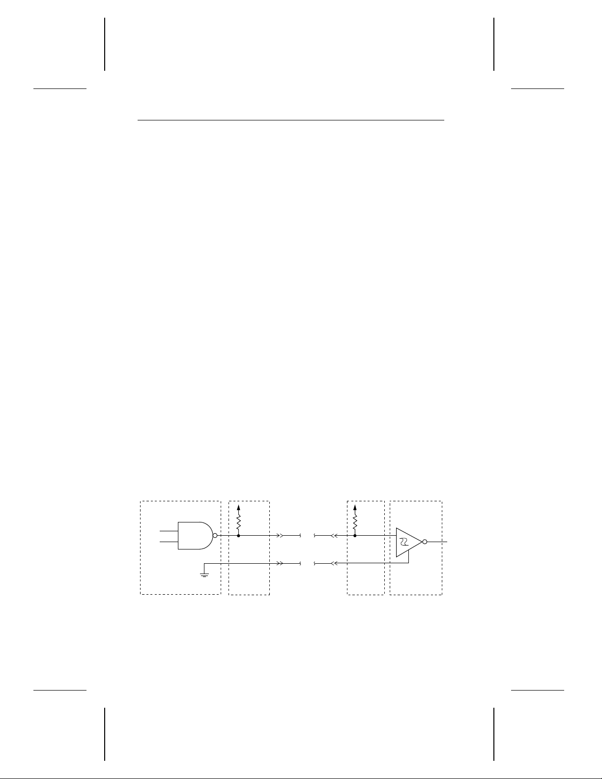
terminator circuitry. Figure 2 shows a single-ended transmitter and
receiver without the active terminator circuitry.
• Transmitter characteristics. The drive uses an ANSI SCSI-compat-
ible, open-collector, single-ended driver. This driver is capable of
sinking a current of 48 mA with a low-level output voltage of 0.4 volts.
• Receiver characteristics. The drive uses an ANSI SCSI single-
ended receiver with hysteresis gate or equivalent as a line receiver.
The loss in the cable is defined as the difference between the voltages
of the input and output signals, as shown below:
Logic level Driver output (x) Receiver input (x)
Asserted (1)
Negated (0)
Figure 2. Singled-ended transmitter and receiver
≤
x ≤ 0.4V 0.0V ≤ x ≤ 0.8V
0.0V
2.5V
≤ x ≤ 5.25V 2.0V ≤ x ≤ 5.25V
Page 22

Decathlon Family Product Manual, Rev. B 13
2.4 Interface and connector configuration
The Seagate ST5660N and ST5660NC drives are differentiated by their
connectors. The ST5660N comes with a standard 50-pin interface connector, a standard 4-pin power connector and an auxiliary SCSI ID block.
The ST5660NC comes with a single, 80-pin SCA interface connector.
The connectors for both drives are discussed below. To minimize noise,
use unshielded mating connectors.
2.4.1 ST5660N interface connector
The ST5660N uses a standard 50-pin, nonshielded, keyed connector.
The connector consists of two rows of 25 male contacts 0.100 inches
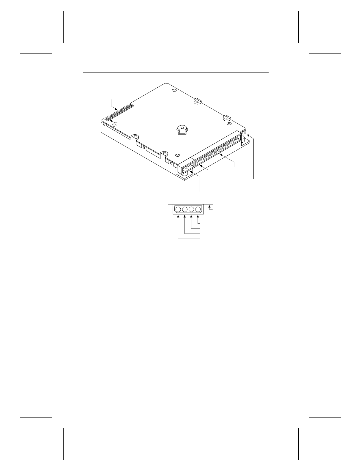
apart. The location of Pin 1 is shown in Figure 3 on page 14. Recommended mating connectors are listed below with their part numbers.
Part numbers for mating 3M connectors compatible with the drive are
listed below. These connectors do not have a center key and are
available with or without a strain relief.
No strain relief
No center key
Closed end
(for cable ends)
Open end
(for daisy chain)
Part numbers for mating Molex connectors compatible with the drive
are listed below. These connectors have a center key.
Closed end
(for cable ends)
Open end
(for daisy chain)
Below are part numbers for strain reliefs that can be used with the Molex
connectors.
Molex strain relief,
preferred version
in Europe
Molex strain relief,
preferred version
in Japan
3M
3425-7000
3M
3425-6000
Molex
39-51-2504
Molex
39-51-2501
Molex 90170-0050
Molex 15-25-1503
With strain relief
No center key
3M
3425-7050
3M
3425-6050
Page 23
J3. Standard
power connector
1
2
3
4
J1. Interface
connector
+5V
+5V return
+12V return
+12V
Circuit
board
pin 1
J8.
Options jumper block
pin 1
J5.
Auxiliary
selection
for
SCSI ID
14 Decathlon Family Product Manual, Rev. B
Figure 3. ST5660N connectors
Page 24

Decathlon Family Product Manual, Rev. B 15
2.4.2 ST5660N interface connector pin assignments
The table below shows the pin assignment for the 50-pin interface
connector. A minus sign (−) indicates an active-low signal.
Signal
Signal name
DB(0)– 2 1
DB(1)– 4 3
DB(2)– 6 5
DB(3)– 8 7
DB(4)– 10 9
DB(5)– 12 11
DB(6)– 14 13
DB(7)– 16 15
DB(P)– 18 17
Ground 19–22 —
Reserved 23–25 —
Terminator power 26 —
Reserved 27–28 —
Ground 29–30 —
ATN– 32 31
Ground 33–34 —
BSY– 36 35
ACK– 38 37
RST– 40 39
MSG– 42 41
SEL– 44 43
C/D– 46 45
REQ– 48 47
I/O– 50 49
Caution. Do not connect pin 25 to ground. If you plug in the connector
upside down, the terminator power on pin 26 is shorted to
ground. This may damage the drive.
pin number
Ground
pin number
Page 25

16 Decathlon Family Product Manual, Rev. B
2.4.3 ST5660NC interface connector
The ST5660NC uses an 80-pin, male, SCA connector. It is a single piece
connector that allows power for the drive to be transmitted through the
SCSI bus. The remote LED, motor start options and additional binary
codes are also placed on the SCSI bus. Pin 1 is shown in Figure 4 on
page 18.
We recommend the AMP Champ 50 mating connector (part number
94-0682-10-1).
2.4.4 ST5660NC interface connector pin assignments
The following table shows the pin assignments for the ST5660NC 80-pin
connector. A minus sign (−) indicates an active-low signal.
Signal Pin number Signal Pin number
+12V 1 12V GND 41
+12V 2 12V GND 42
+12V 3 12V GND 43
+12V 4 12V GND 44
NC 5 NC 45
NC 6 NC 46
NC 7 GND 47
NC 8 GND 48
NC 9 GND 49
NC 10 GND 50
IO− 11 GND 51
REQ− 12 GND 52
C/DQ− 13 GND 53
SEL− 14 GND 54
MSG− 15 GND 55
RST− 16 GND 56
ACK− 17 GND 57
BSY− 18 GND 58
ATN− 19 GND 59
DBP− 20 GND 60
DB7− 21 GND 61
DB6− 22 GND 62
DB5− 23 GND 63
DB4− 24 GND 64
DB3− 25 GND 65
Page 26

Decathlon Family Product Manual, Rev. B 17
Signal Pin number Signal Pin number
DB2− 26 GND 66
DB1− 27 GND 67
DB0− 28 GND 68
NC 29 GND 69
NC 30 GND 70
NC 31 GND 71
NC 32 GND 72
NC 33 GND 73
+5V 34 5V GND 74
+5V 35 5V GND 75
+5V 36 5V GND 76
NC 37 LEDC
MTRON
SCSIA0
SCSIA2
2
4
4
38 DLYDST
39 SCSIA1
40 SCSIA3
1
3
4
4
77
78
79
80
Notes 1 to 4 indicate pins also represented on the options jumper block.
Notes:
1. Drive activity signal; same as remote LED setting.
2. Asserted by host to enable Motor Start option (starts motor
through the SCSI bus command). Settings are mutually exclusive option.
3. Asserted by host to enable the Delayed Motor Start option
(motor starts at power on or after a delay of 12 seconds times
the drive ID). This is a mutually-exclusive option.
4. Binary code on A0, A1, A2 and A3 asserted by host to set up
SCSI bus ID in drive.
Page 27
pin 1
J8.
Options jumper block
pin 1
18 Decathlon Family Product Manual, Rev. B
Figure 4. ST5660NC connectors
2.5 Interface cable requirements
A characteristic impedance of 100 ohms +10% is recommended for the
unshielded flat or twisted pair interface cable. However, most available
cables have a somewhat lower characteristic impedance. To minimize
discontinuities and signal reflections, do not use cables of different
impedances in the same bus. Implementation may require tradeoffs in
wielding effectiveness, cable length, the number of loads and the transfer
rates to achieve satisfactory system operation. If shielded and unshielded cables are mixed within the same bus, the effect of impedance
mismatch must be carefully considered. This is especially important for
maintaining adequate margin for Fast SCSI transfer rates.
To minimize noise, use 28 AWG or larger 50-conductor flat cable or
25-conductor twisted pair ribbon cable. The following are part numbers
for nonshielded flat cables we recommend:
Part Manufacturer
Flat Cable 3M-3365-50
Twisted Pair Spectra Twist-N-Flat 455-248-50
Page 28

Decathlon Family Product Manual, Rev. B 19
2.5.1 Interface cable length for asynchronous
operation
The SCSI interface cable must meet the following requirements for
normal operation:
• The cable cannot be longer than 6.0 meters.
• Cable stubs cannot be more than 0.1 meter long and must be
separated by at least 0.3 meter.
2.5.2 Interface cable for Fast SCSI operation
When using fast synchronous data transfer rates, the SCSI interface
cable must meet the following additional requirements:
• The cable cannot be longer than 3.0 meters.
• The cable should not attenuate a 5 MHz signal more than 0.095 dB
per meter.
• The DC resistance at 20°C must not exceed 0.230 ohms per meter.
• A shielded, twisted-pair cable should not have a propagation delay
delta greater than 20 nsec per meter.
2.6 Options jumper block
Both ST5660N and ST5660NC have the options jumper block at J8 (see
Figure 3 on page 14 and Figure 4 on page 18 for its location). The options
jumper block allows you to manually:
• Enable or disable active termination
• Set the SCSI ID address
• Select the terminator power source
• Enable parity
• Activate the motor start/stop option
• Attach a remote LED
These functions are represented on the options jumper block for both
drives. Figure 5 on page 21 shows how to configure the jumpers.
However, the ST5660NC allows you to control some of these functions
through the SCSI bus (the pin assignment chart on page 17 shows the
functions that can be programmed through the bus).
Page 29

20 Decathlon Family Product Manual, Rev. B
The jumper block accepts 2-mm jumpers. Spare jumpers are included
with the drive attached to the pins shown in the figure. If you need
additional jumpers, use the jumpers listed below or equivalent.
Manufacturer Part number
Seagate 13211-001
Du Pont 89133-001
Methode 8618-202-70
2.6.1 Active Termination
The ST5660N and ST5660NC use a jumper on the options jumper block
to enable active termination. You can order the drive with the active
termination enabled or disabled. Active termination is enabled when a
jumper is placed on pins 19 and 20 of the options jumper block. Active
termination is disabled when there is no jumper on pins 19 and 20 of the
options jumper block.
2.6.2 SCSI address
SCSI ID is set on the ST5660N and ST5660NC using pins 1 and 2, 3 and
4 and 5 and 6 on the options jumper block. The drives are shipped with
jumpers on pins 1 and 2 and pins 3 and 4 for configuring the SCSI ID.
This means the drives have a default address of SCSI ID 3. You may
need to reset the drive’s address for your operation. Refer to your host
adapter reference manual for its preferred addressing scheme.
2.6.3 Terminator power source selection
To select the termination power source, install jumpers as follows:
• To select the drive power connector as the termination power source
for the resistor packs, install a jumper on pins 23 and 24 of the options
jumper block.
• To select the SCSI connector as the termination power source for the
resistor packs, install a jumper on pins 21 and 23 of the options jumper
block.
• To provide terminator power to the SCSI connector and the drive
terminator packs, install jumpers on pins 21 and 23 and pins 22 and 24
of the options jumper block. This is the default.
• To provide terminator power to the SCSI connector from the drive
power connector only, install a jumper on pins 22 and 24 of the options
jumper block.
Page 30
SCSI ID 0
SCSI ID 1
SCSI ID 2
SCSI ID 3
SCSI ID 4
SCSI ID 5
Note.
1. All other pins
are reserved. Do
not use them.
2. Jumpers on
pins 28 and 30
and 32 and 34
are spares; these
pins do not
require jumpers.
SCSI ID 6
SCSI ID 7
Remote LED
connection
Reserved
Do not use
Remote start
Parity enable
Terminator
disable
Power from drive
power connector
Power from
SCSI bus
Power from drive
power connector
and to SCSI bus
Power to SCSI
bus only
J8. Options jumper block
Circuit board
side up.
111291078563
4
13
14
1
2
15161718192021
22
3334313229302728252623
24
Spares
Decathlon Family Product Manual, Rev. B 21
Figure 5. Options jumper block (J8) settings
Page 31

22 Decathlon Family Product Manual, Rev. B
2.6.4 Parity enable option
When a jumper is installed on pins 17 and 18 of the options jumper block,
the parity bit is used. This is the default. When a jumper is not installed
on pins 17 and 18 of the options jumper block, the parity bit is not used.
2.6.5 Start/stop option
When a jumper is installed on pins 15 and 16 of the options jumper block,
the drive waits for a Start/Stop Unit command from the host before
starting or stopping the spindle motor.
2.6.6 Remote LED connection
Pins 9 and 10, located on the options jumper block, are reserved for a
remote LED. Pin 9 is ground. Use any 2-pin, 2-mm connector and, if you
are placing the drive in an array configuration, we recommend the
LiteOn (part number LTL-3231A) LED or equivalent.
2.7 Auxiliary SCSI ID block
The ST5660N comes with an auxiliary SCSI ID block at J5. It is located
next to the interface connector on the underside of the printed circuit
board as shown in Figure 6. This location may be used to set the SCSI
ID instead of the options jumper block.
SCSI address is set using either the options jumper block (J8) or the
auxiliary SCSI ID block (J5) but not both. If you use the auxiliary SCSI
ID block, leave the pins for SCSI ID on the options jumper block open.
The SCSI ID can be affected if jumpers are set at both locations.
2.8 Daisy chaining
The drive can be connected in a daisy chain with a maximum of eight
SCSI devices (including the host) that have single-ended drivers and
receivers. Each SCSI device must be set to a unique SCSI ID number.
SCSI ID 7 is usually used for the host adapter.
All signals are common between all SCSI devices. The SCSI devices at
both ends of the daisy chain must be terminated; the intermediate SCSI
devices should not be terminated.
Page 32
J5.
SCSI ID
SCSI ID 0
SCSI ID 1
SCSI ID 2
SCSI ID 3
SCSI ID 4
SCSI ID 5
SCSI ID 6
SCSI ID 7
Circuit board
bottom view
214
3
6
5
pin 1
Decathlon Family Product Manual, Rev. B 23
Figure 6. ST5660N auxiliary SCSI ID jumper block (J5) settings
Page 33

24 Decathlon Family Product Manual, Rev. B
2.9 Hot-plugging
You can connect and disconnect the I/O and power cables for each SCSI
device in a daisy chain without powering down the system. This is called
hot-plugging. When hot-plugging, the following conditions must be met:
• The terminators at either end of the SCSI bus are in place.
• The drive you are disconnecting or connecting is not the device
supplying terminator power or terminating resistance to the bus.
• All I/O transactions are complete before you install or remove a drive.
To avoid damage to the disc and head, the spindle must be completely
stopped and the heads must be parked before you remove the drive from
the system. There are two ways to stop the spindle and park the heads:
• If the drive is not configured to use the remote start/stop feature,
disconnect the DC power cable from the drive DC power connector
and wait 30 seconds.
• If the drive is configured to use the remote start/stop feature, issue the
Start/Stop Unit command and wait 30 seconds.
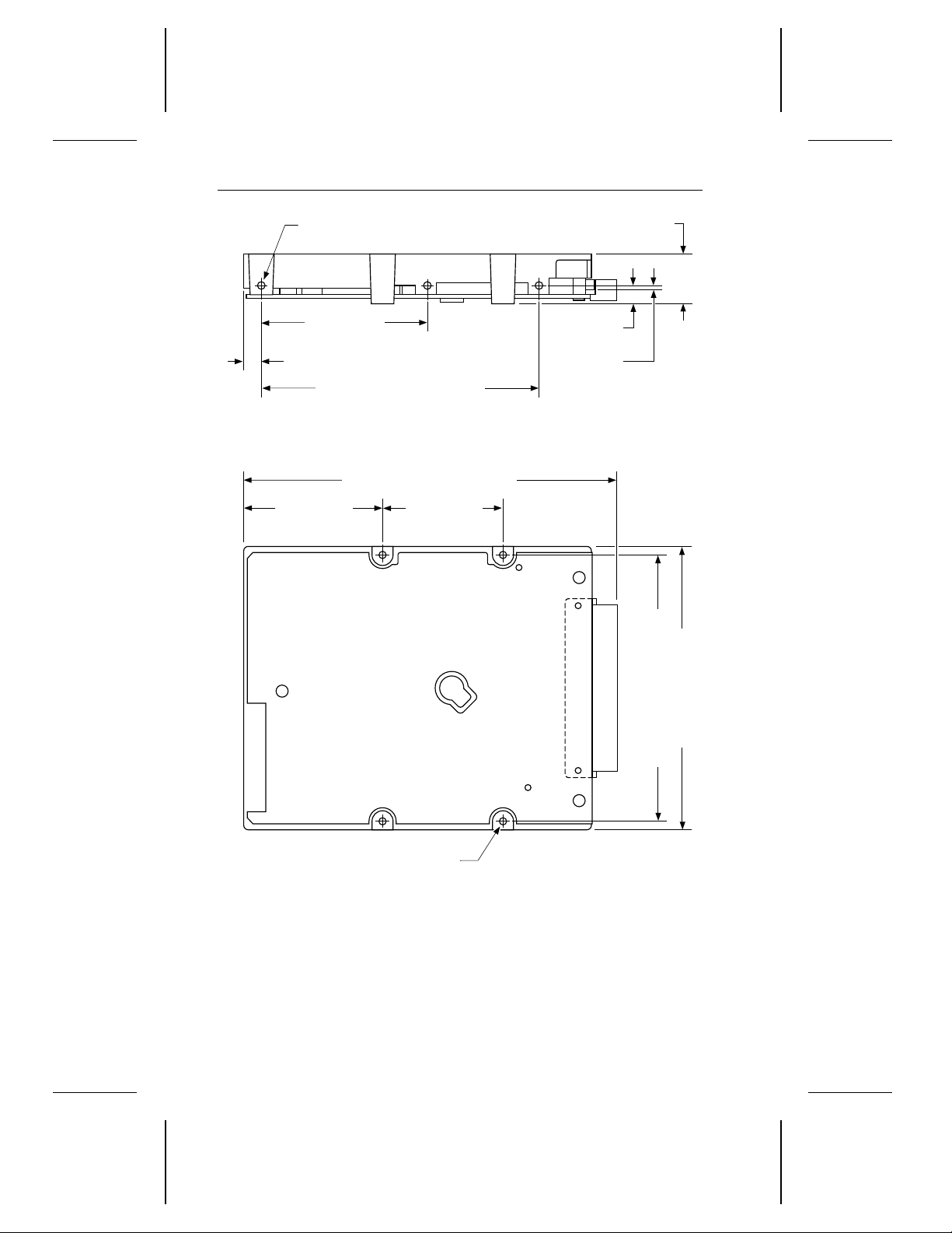
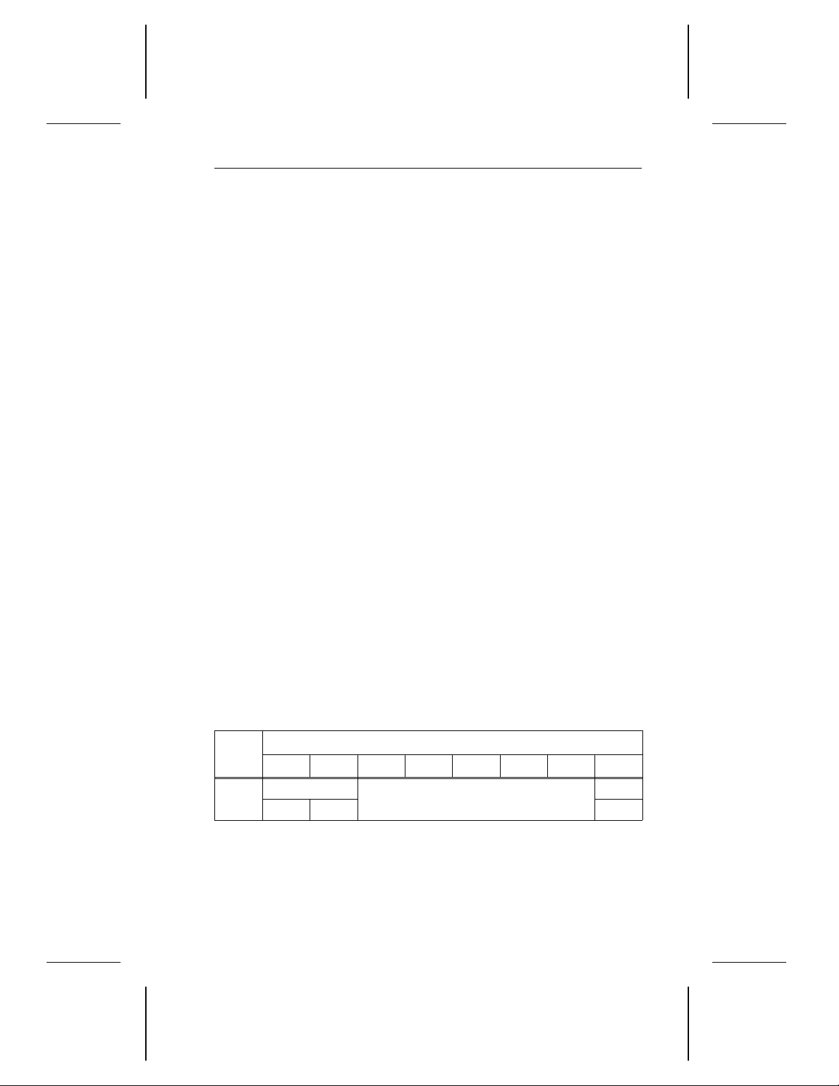
2.10 Mounting the drive
The ST5660N and ST5660NC are 3.5-inch form-factor drives with a
one-inch profile. You can mount them securely in the computer using
either the bottom or side mounting holes, as described below. Position
the drive so that you do not strain or crimp the cables. Figure 7 shows
the drive mounting dimensions and the side and bottom mounting holes
for the ST5660N. Figure 8 on page 26 shows the drive mounting dimensions and the side and bottom mounting holes for the ST5660NC.
Bottom mounting holes. Insert 6-32 UNC-2A mounting screws in the
four available bottom mounting holes. Do not insert the screws more than
0.20 inches (6 turns) into the drive frame.
Side mounting holes. Insert 6-32 UNC-2A mounting screws in four of
the six available side mounting holes. Use two mounting holes on each
side of the drive. Do not insert the screws more than 0.20 inches (6 turns)
into the drive frame.
Caution. To avoid damaging the drive:
• Use only mounting screws of the type specified.
• Gently tighten the mounting screws—do not apply more than 6 inch-lb
of torque.
Page 34
5.000 +0.000 −0.0200 (127.000 +0.000 −0.508)
1.985 ± 0.020
(50.419 ± 0.508)
1.750 ± 0.010
(44.450 ± 0.254)
3.750 ± 0.010 (95.250 ± 0.254)
4.020 max (102.108)
0.748 max
(19.000)
2.362 ± 0.010
(59.995. ± 0.254)
0.240 ± 0.020 (6.096
± 0.508)
4.000 ± 0.020 (101.60
± 0.508)
0.250 ± 0.010
(6.350 ± 0.254)
Six 6-32 UNC-2B threaded holes
Max screw insertion depth: 0.20 inch
Four 6-32 UNC-2B threaded holes
Max screw insertion depth: 0.20 inch
Decathlon Family Product Manual, Rev. B 25
The mounting dimensions for the ST5660N and ST5660NC are shownin
Figures 7 and 8 respectively. All dimensions are shown in both inches
and millimeters. Millimeters are shown in parenthesis.
Figure 7. ST5660N mounting dimensions
Page 35
5.120 ± 0.020 (130.000 ± 0.508)
1.985 ± 0.020
(50.419 ± 0.508)
1.750 ± 0.010
(44.450 ± 0.254)
3.750 ± 0.010 (95.250 ± 0.254)
4.020 max (102.108)
0.748 max
(19.000)
2.362 ± 0.010
(59.995. ± 0.254)
0.240 ± 0.020 (6.096
± 0.508)
4.000 ± 0.020 (101.60
± 0.508)
0.250 ± 0.010
(6.350 ± 0.254)
0.069 ± 0.020
(1.725 ± 0.508)
Six 6-32 UNC-2B threaded holes
Max screw insertion depth: 0.20 inch
Four 6-32 UNC-2B threaded holes
Max screw insertion depth: 0.20 inch
26 Decathlon Family Product Manual, Rev. B
Figure 8. ST5660NC mounting dimensions
Page 36
Decathlon Family Product Manual, Rev. B 27
3.0 Command set
The drive supports a subset of the Group 0 and Group 1 standard SCSI
commands. The commands are described in this section.
3.1 Command descriptor block
The initiator makes a request to the drive by sending a command
descriptor block (CDB) to the drive. Each CDB has the following common
characteristics:
• Byte 0 always contains the operation code.
• The three most significant bits (bits 7–5) of byte 1 contain the logical
unit number (LUN), which is always zero.
• If the link bit is zero, the flag bit must be zero; otherwise, the drive
returns a check condition status. If the link bit is one and the drive
completes the command without error, the flag bit specifies which
message the drive returns to the initiator. If the flag bit is zero, the
drive sends the
one, the drive sends the
sage.
linked command complete
linked command complete with flag
message. If the flag bit is
mes-
3.2 Status byte codes
After the drive terminates each command, the drive sends the status byte
(shown below) to the initiator during the status phase, unless the command is terminated by one of the following methods:
• An abort message
• A bus device reset message
• A hard reset
• A catastrophic reset condition
Bytes
0
7 6 5 4 3 2 1 0
Reserved
0 0 0
Bits
Status byte code
Rsrvd
Page 37

28 Decathlon Family Product Manual, Rev. B
The
status byte code
Good status. The drive has successfully completed a command.
00
H
Check condition status. The drive detected an error, an excep-
02
H
can be any of the following:
tion or an abnormal condition. In response, the initiator may issue
a Request Sense command to determine the nature of the condition.
Busy status. The drive is busy and is unable to accept a command
08
H
from an initiator. The initiator retries the command later. The drive
returns a busy status if 1) the initiator has not sent the disconnect
message and tries to queue a command or 2) the initiator rejects
the disconnect message and the queue is not empty.
Intermediate status. The drive successfully completed a com-
10
H
mand that was one of a series of linked commands without issuing
a check condition status or reservation conflict status. If the drive
had not returned an intermediate status, the series of linked
commands would have been terminated.
Reservation conflict status. A SCSI device tried to access the
18
H
drive, but was unable to because the drive was already reserved
by another SCSI device.
Queue full status. The drive received a command but rejected it
28
H
because the queue was full. The drive only uses this status if
tagged command queuing is implemented.
Page 38

Decathlon Family Product Manual, Rev. B 29
3.3 Supported commands
The drive supports the commands listed below.
Group 0 commands Operation code
Test Unit Ready 00
Rezero Unit 01
Request Sense 03
Format Unit 04
Reassign Blocks 07
Read 08
Write 0A
Seek 0B
Inquiry 12
Mode Select 15
Reserve 16
Release 17
Mode Sense 1A
Start/Stop Unit 1B
Receive Diagnostic Results 1C
Send Diagnostic 1D
H
H
H
H
H
H
H
H
H
H
H
H
H
H
H
H
Group 1 commands Operation code
Read Capacity 25
Read Extended 28
Write Extended 2A
Seek Extended 2B
Write and Verify 2E
Verify 2F
Read Defect Data 37
Write Data Buffer 3B
Read Data Buffer 3C
Read Long 3E
Write Long 3F
H
H
H
H
H
H
H
H
H
H
H
Page 39
30 Decathlon Family Product Manual, Rev. B
3.4 Group 0 commands
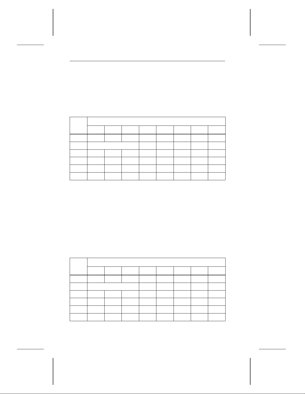
3.4.1 Test Unit Ready command (00
The Test Unit Ready command verifies that the drive is ready; it is not a
request for a self-test. If the drive accepts an appropriate media access
command without encountering an error, it returns a good status.
Bits
Bytes
7 6 5 4 3 2 1 0
0 0 0 0 0 0 0 0 0
1 LUN 0 0 0 0 0
2 0 0 0 0 0 0 0 0
3 0 0 0 0 0 0 0 0
4 0 0 0 0 0 0 0 0
5 0 0 0 0 0 0 Flag Link
)
H
3.4.2 Rezero Unit command (01H)
The Rezero Unit command requests that the drive set its logical block
address to zero and return the read/write heads to the track (or cylinder)
containing logical block 0.
This command is intended for systems that disable retries and have the
initiator perform error recovery. It is longer than a seek to logical block
address 0 and should be used if seek errors are encountered.
When used with a host adapter that supports disconnection, the drive
disconnects when it receives this command.
Bytes
7 6 5 4 3 2 1 0
0 0 0 0 0 0 0 0 1
1 LUN 0 0 0 0 0
2 0 0 0 0 0 0 0 0
3 0 0 0 0 0 0 0 0
4 0 0 0 0 0 0 0 0
5 0 0 0 0 0 0 Flag Link
Bits
Page 40
Decathlon Family Product Manual, Rev. B 31
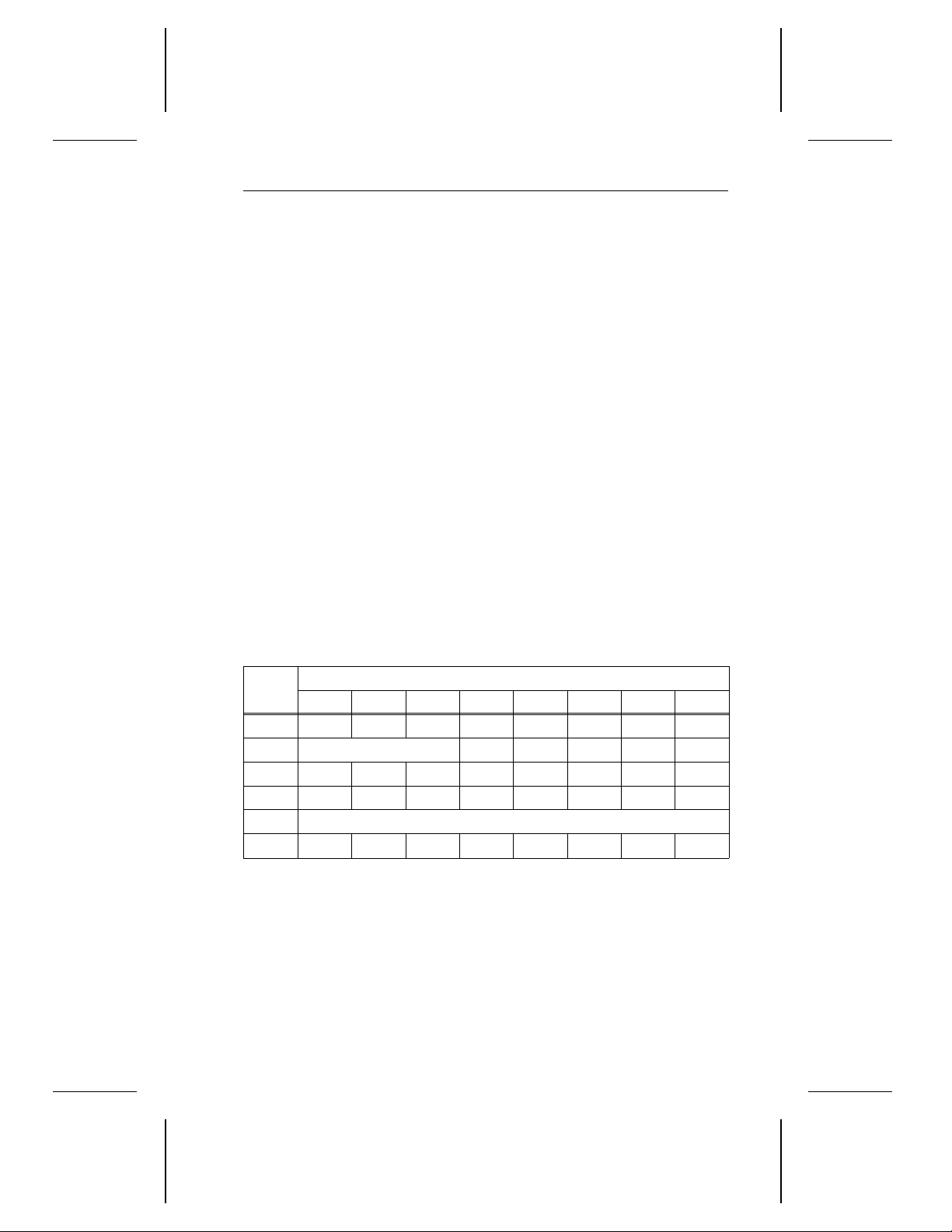
3.4.3 Request Sense command (03H)
The Request Sense command requests the drive to transfer sense data
to the initiator in the additional sense data format. The additional sense
format is described in Appendix B.
The sense data applies to the previous command on which a check
condition status was returned. This sense data is saved for the initiator
until:
• The initiator requests the sense data using the Request Sense command, or
• Another command is received from the initiator that issued the command, resulting in the check condition status.
If any of the following fatal errors occur during a Request Sense command, the drive sends a check condition status and the sense data may
be invalid.
• The drive receives a nonzero reserved bit in the CDB.
• An unrecovered parity error occurs on the data bus.
• A malfunction prevents return of sense data.
If any other error occurs during the Request Sense command, the drive
returns sense data with a good status.
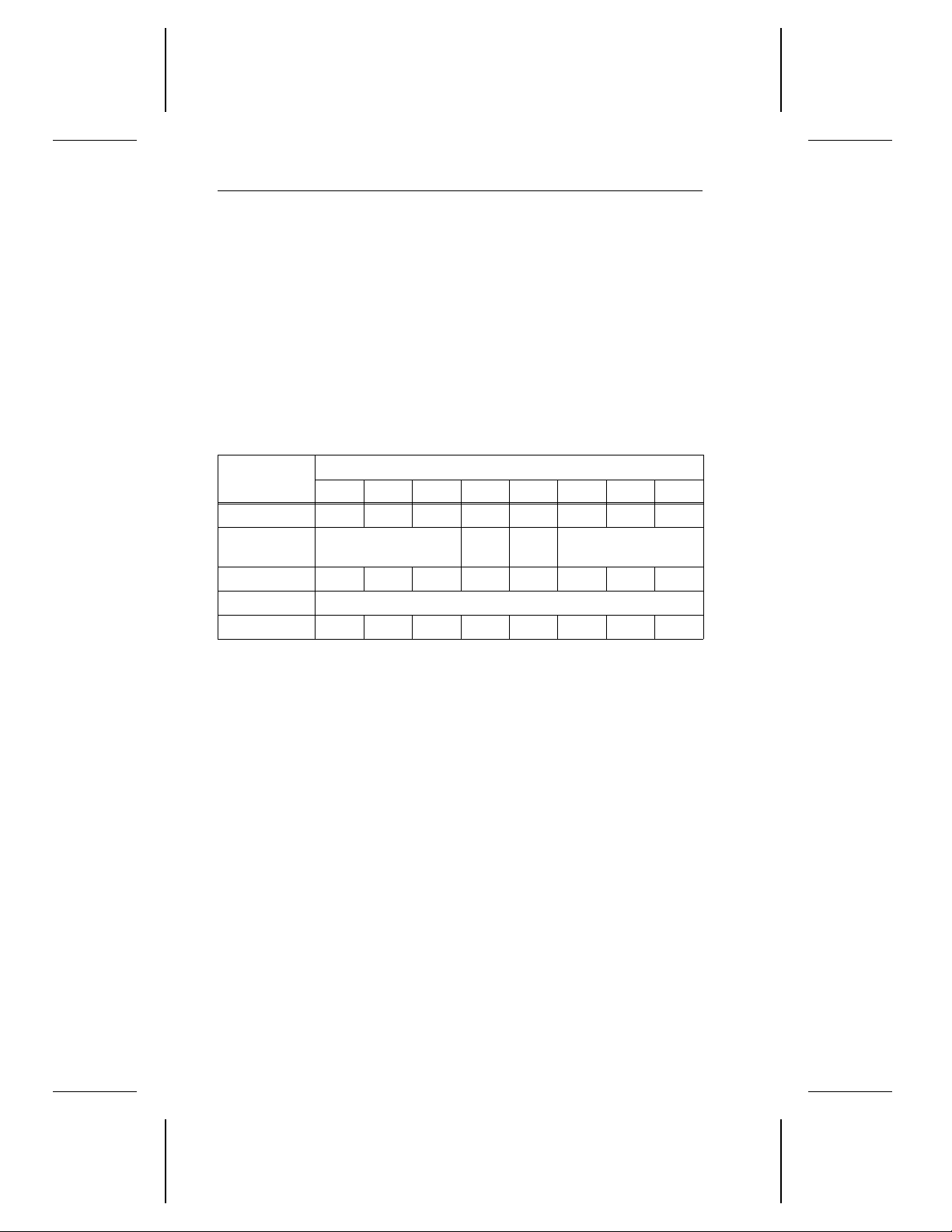
Bytes
0 0 0 0 0 0 0 1 1
1 LUN 0 0 0 0 0
2 0 0 0 0 0 0 0 0
3 0 0 0 0 0 0 0 0
4 Allocation length
5 0 0 0 0 0 0 Flag Link
Byte 4 The
7 6 5 4 3 2 1 0
allocation length
the initiator has allocated for returned sense data. The drive
returns up to, but no more than, 22 bytes of sense data. Therefore, if you want the initiator to receive all of the sense data, set
the allocation length to 22 bytes or more. If you set the allocation
length to zero, no sense data is returned.
specifies the maximum number of bytes
Bits
Page 41
32 Decathlon Family Product Manual, Rev. B
3.4.4 Format Unit command (04H)
The Format Unit command formats the disc so that all of the user-addressable data blocks can be accessed. In addition, the disc can be
certified and control structures can be created for managing the disc and
defects.
If the specified logical unit is reserved, the Format Unit command is
rejected with a reservation conflict status. Extent reservations are not
supported. See Section 3.4.11 for more information about reservations.
The initiator can specify (or not specify) sectors to be reallocated during
the formatting process.
Bytes
0 0 0 0 0 0 1 0 0
1 LUN
2 0 0 0 0 0 0 0 0
3–4 Interleave
5 0 0 0 0 0 0 Flag Link
Byte 1 The
Bytes 3–4 The
7 6 5 4 3 2 1 0
format data
bit,
and the
tion 3.4.4.2.
interleave
value. However, the drive always formats the disc with an
interleave of 1:1.
(Fmt Data) bit, the
Defect list format
field is not supported. It can contain any
Bits
Fmt
Data
Cmp
lst
Defect list format
complete list
field are described in Sec-
(Cmp lst)
Page 42

Decathlon Family Product Manual, Rev. B 33
3.4.4.1 Defect lists
When the Format Unit command is issued, media defect information can
be gathered from several sources. Four of these sources—primary
defect list, certification defect list, data defect list and grown defect
list—are defect lists written to the drive. They are defined below. Assignments in Byte 1 of the defect list header—described in Section 3.4.4.3—
determine the use of the defect list during formatting. The Reassign
Blocks and Read Defect Data commands also use these lists.
• The
• The
• The
• The
primary defect list (PList)
of media defects found when the drive is manufactured and written to
the disc in an area that is not directly accessible by the user. These
defects are considered permanent and cannot be changed.
certification defect list (CList)
incorrectly formatted during the Format Unit command. This list is
created when the DCRT bit of the defect list header is set to zero and
is added to the GList.
data defect list (DList)
the drive during a data-out phase of the current Format Unit command.
The drive sends the DList in the last bytes of the defect list described
in Section 3.4.4.3.
grown defect list (GList)
or detected by the target but does not include defects from the PList.
The GList includes defects detected by the format operation during
media certification, defects previously identified with a Reassign
Blocks command and defects previously detected by the target and
automatically reallocated. When the CmpLst bit is set to zero, the
DLists provided to the target during previous and the current Format
Unit commands are included in the GList.
(sometimes called the ETF list) is a list
is a list of sectors that the drive
is a list of sectors the initiator supplies to
is a list of defects supplied by the initiator
3.4.4.2 Format Unit parameters
For each format listed below, except the default format, the initiator sends
a defect list header. This header is described in Section 3.4.4.3. The
bytes-from-index format is described in Section 3.4.4.4 and the physical
sector format is described in Section 3.4.4.5. The block format is not
discussed.
Page 43
34 Decathlon Family Product Manual, Rev. B
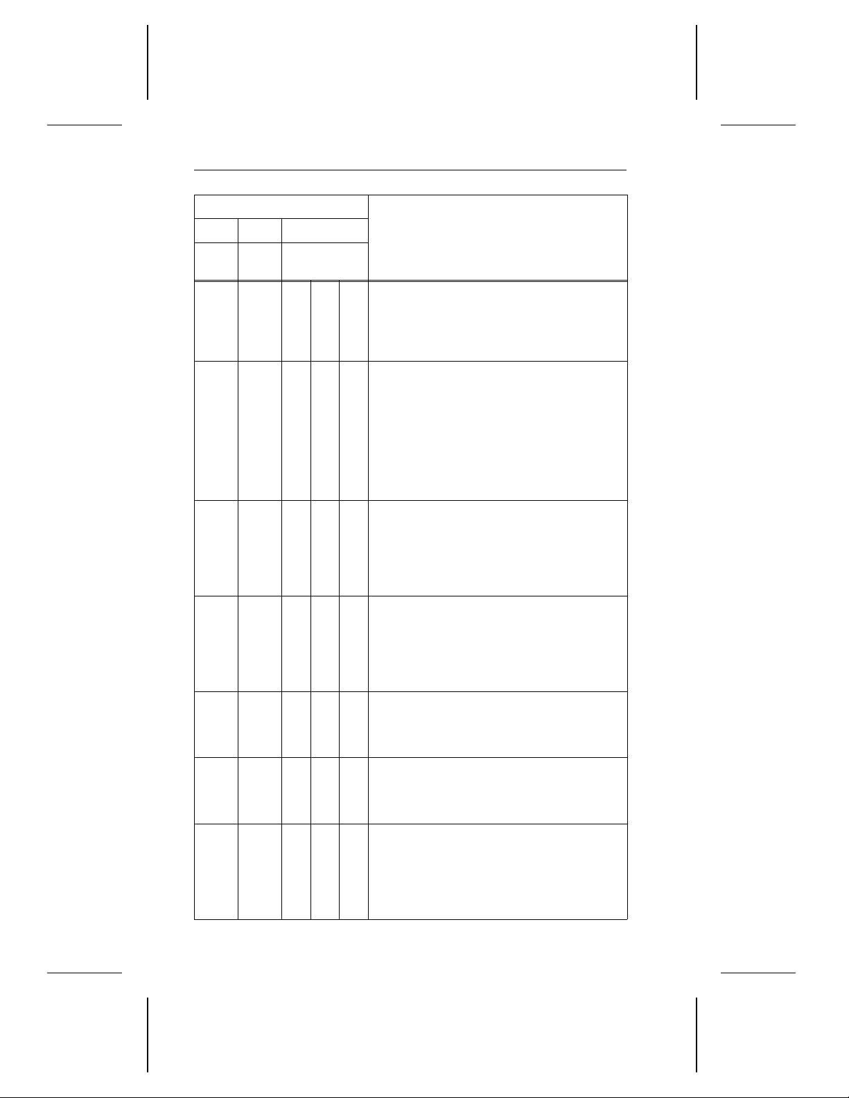
Byte 1 of CDB
Bit 4 Bit 3 Bit 2–Bit 0
Fmt
Data
Cmp
0 0 X X X
1 0 0 X X
1 0 1 0 0
1 0 1 0 1
1 1 0 X X
1 1 1 0 0
1 1 1 0 1
Lst
Defect List
Format
Description
Default format
send the defect list header or DList to
the drive. The drive reallocates all
sectors in the PList and erases the
GList.
Extended format.
defect list header, but no DList. Before
formatting, the reassigned LBAs are
merged into the grown defect list
(GList). All sectors are then reallocated
using the PList and the current GList. At
the end of the format, the new GList and
defect tables are stored on a reserved
area of the disc.
. The initiator does not
The initiator sends a
Format option with the GList and DList.
The initiator does not send a DList to
the drive. The drive uses the existing
GList to find defects and adds new
defects to the existing GList in the bytesfrom-index format.
Format option with the GList and DList.
The initiator does not send a DList to
the drive. The drive uses the existing
GList to find defects and adds new
defects to the existing GList in the
physical sector format.
Format option without GList or DList
selected. The initiator sends a defect list
header, but no DList. The drive erases
any previous GList.
Format option with DList
sends the defect list header followed by
a DList in the bytes-from-index format.
The drive erases any previous GList.
. The initiator
is
Format option with DList and without
GList
. The initiator sends a defect list
header followed by a DList of defects to
be reallocated. The DList is in the
physical sector format. Any previous
GList is erased.
Page 44
Decathlon Family Product Manual, Rev. B 35
3.4.4.3 Defect list header and defect list
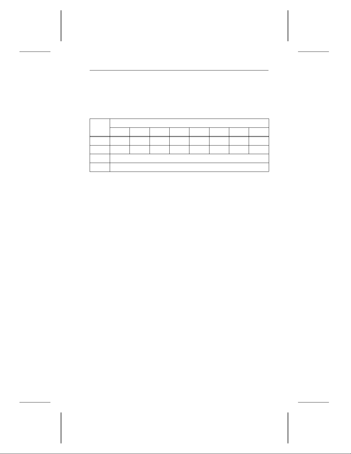
The defect list, shown below, contains a 4-byte header, followed by one
or more defect descriptors. Byte 1 of the defect list header determines
whether the P and C defects are reallocated.
Bytes
0 0 0 0 0 0 0 0 0
1 FOV DPRY DCRT STPF 0 0 0 0
2–3 Defect list length
4–
Byte 1 If the
7 6 5 4 3 2 1 0
n
FOV
bit is 1, the DPRY, DCRT and STPF bits are
interpreted. If the FOV bit is 0, the DPRY, DCRT and STPF
bits are checked for zeros.
The DPRY bit is always 0. The defects described in the
PList are reallocated during formatting. The drive sends a
check condition status if it cannot find the PList.
If the
DCRT
bit is 1, the drive does not verify the data written
during the format. Therefore, no CList for this format is
created or reallocated. If the DCRT is 0, the drive verifies
the data written during the format, creates a CList and
reallocates sectors that were incorrectly formatted.
If the
STPF
bit is 1, the drive stops formatting if it encounters
an error while accessing either the P or G defect list. If the
STPF
bit is 0, the drive continues formatting even though it
has encountered an error while accessing either the P or G
defect list.
Bits
Defect descriptor
Bytes 2–3 The
that follows the header. For each sector to be reallocated,
the defect list contains one defect descriptor that contains
8 bytes in either the bytes-from-index format or the physical
sector format. These formats are explained in Sections 3.4.4.4 and 3.4.4.5, respectively.
Bytes 4–
n
The two types of defect descriptors are described in Sections 3.4.4.4 and 3.4.4.5.
defect list length
is the length, in bytes, of the defect list
Page 45
36 Decathlon Family Product Manual, Rev. B
3.4.4.4 Defect descriptor—bytes-from-index format
Defects are specified in the bytes-from-index format when the defect list
format field is 100
Section 3.4.4.
. See byte 1 of the Format Unit command in
Binary
Each defect descriptor in the
bytes-from-index
format specifies the
beginning of a single-byte defect location on the disc. Each defect
descriptor is comprised of the cylinder number of the defect, the head
number of the defect and the number of bytes-from-index to the defect
location. The defect descriptors are always listed in ascending order.
A value for defect bytes-from-index of FFFFFFFF
(which means reas-
H
sign the entire track) is illegal.
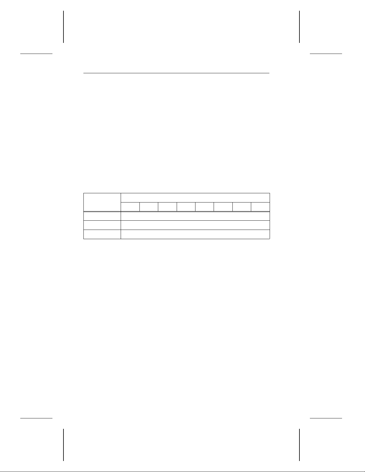
The information in the following table is repeated for each defect.
Bytes
7 6 5 4 3 2 1 0
Bits
0–2 Cylinder number of defect
3 Head number of defect
4–7 Defect bytes-from-index
3.4.4.5 Defect descriptor—physical sector format
Defects are specified in the physical sector format when the defect list
format field is 101
Section 3.4.4.
Each defect descriptor for the physical sector format specifies a sectorsize defect location comprised of the cylinder number of the defect, the
head number of the defect and the defect sector number. The defect
descriptors must be in ascending order.
. See byte 1 of the Format Unit command in
Binary
A defect sector number of FFFFFFFF
(which means reassign the entire
H
track) is illegal.
Note. The initiator cannot use any previously defined C, G or D lists if
the Mode Select command has changed the sector size (block
length). For more information on the Mode Select command, see
Section 3.4.10.
Page 46
Decathlon Family Product Manual, Rev. B 37
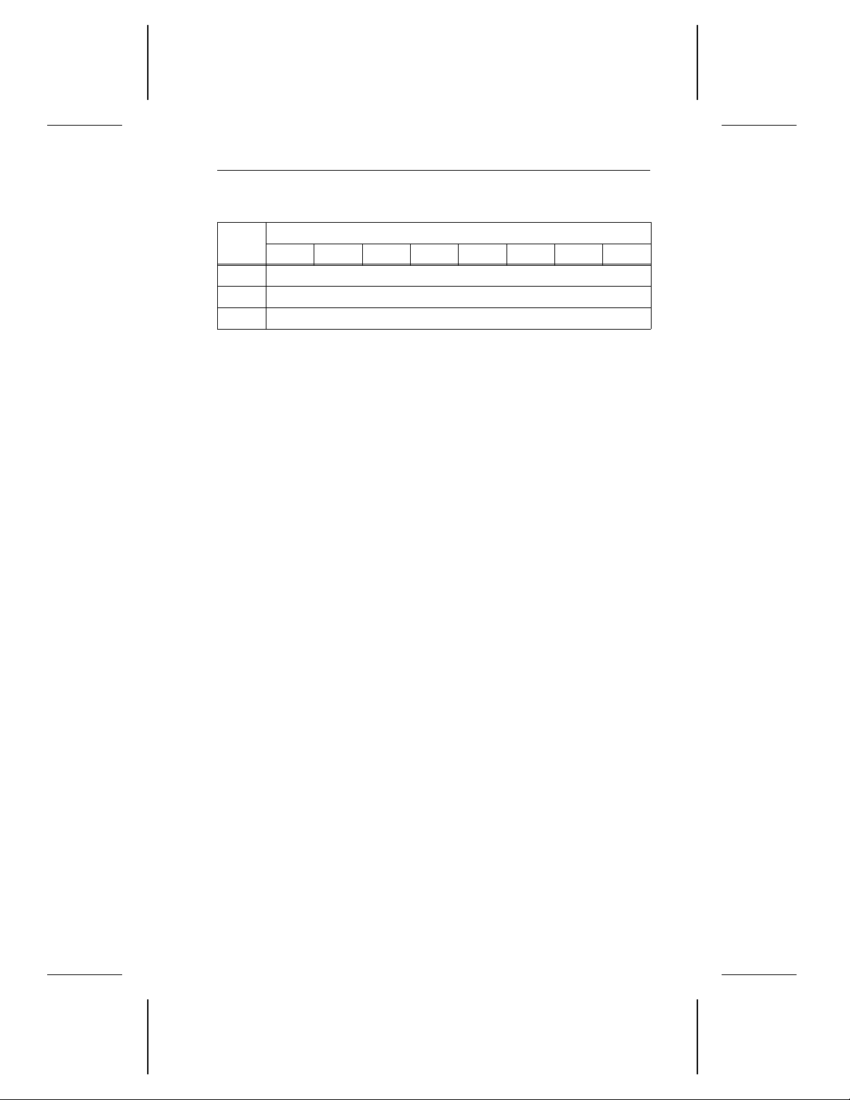
The information in the following table is repeated for each defect.
Bytes
0–2 Cylinder number of defect
3 Head number of defect
4–7 Defect sector number
7 6 5 4 3 2 1 0
Bits
3.4.5 Reassign Blocks command (07H)
When the drive receives the Reassign Blocks command, it reassigns
defective logical blocks to available spare sectors. Use this command
when the AWRE and ARRE bits are set to 0, which means that automatic
reallocation is disabled. These bits are contained in byte 2 of the Error
Recovery page, which is described in Appendix C.1.
If the system supports disconnection, the drive disconnects while executing this command. The initiator uses this command to immediately
reallocate any block (sector) that requires the drive to recover data using
ECC if the automatic reallocation feature is not enabled.
Note. Before sending this command, the initiator should recover the data
from the logical blocks to be reassigned. After completing this
command, the initiator can write the recovered data to the same
logical block addresses.
After sending the Reassign Blocks command, the initiator transfers a
defect list containing the logical block addresses to be reassigned. The
drive reassigns the logical blocks. The data contained in the logical
blocks is not preserved.
The drive can repeatedly assign a logical block to multiple physical
addresses until there are no more spare locations available on the disc.
Page 47
38 Decathlon Family Product Manual, Rev. B
If the drive does not have enough spare sectors to reassign all of the
defective logical blocks, the command terminates with a check condition
status and the sense key is set to media error. The logical block address
of the first logical block not reassigned is returned in the information bytes
of the sense data.
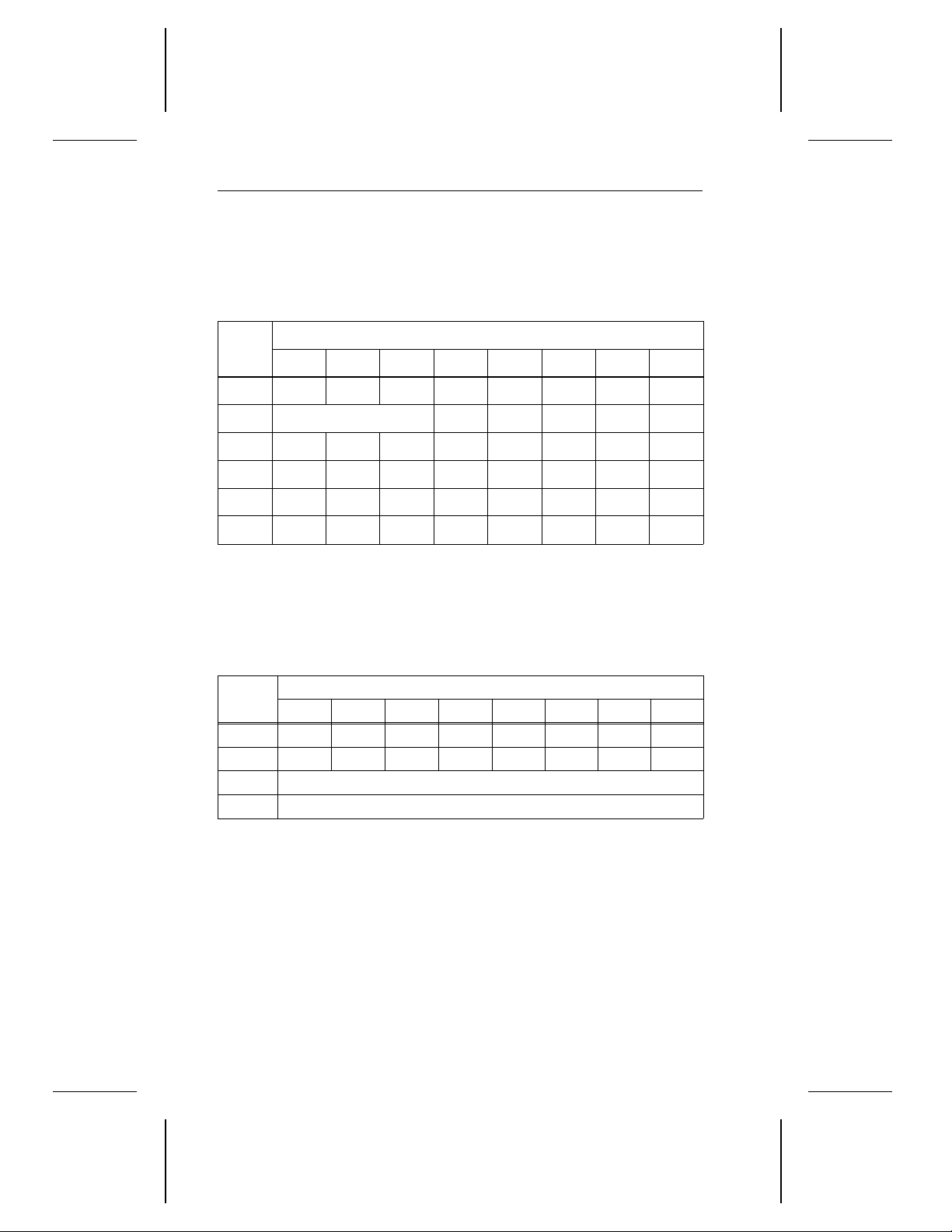
Bytes
7 6 5 4 3 2 1 0
0 0 0 0 0 0 1 1 1
1 LUN 0 0 0 0 0
2 0 0 0 0 0 0 0 0
3 0 0 0 0 0 0 0 0
4 0 0 0 0 0 0 0 0
5 0 0 0 0 0 0 Flag Link
Bits
3.4.5.1 Reassign Blocks defect list
The Reassign Blocks defect list contains a 4-byte header followed by one
or more defect descriptors. The length of each defect descriptor is 4
bytes.
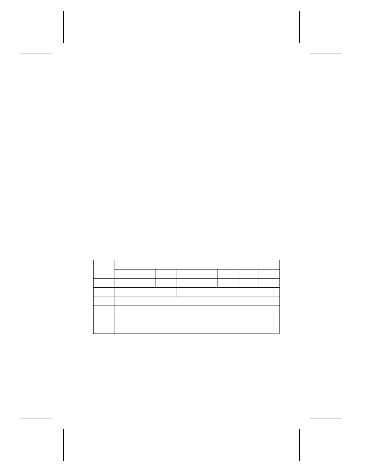
Bytes
0 0 0 0 0 0 0 0 0
1 0 0 0 0 0 0 0 0
2–3 Defect list length
4–
n
7 6 5 4 3 2 1 0
Defect descriptors
Bits
Byte 1 The
the defect descriptors that follow. The defect list length is
equal to four times the number of defect descriptors.
Bytes 4–
n
The
address of the defect. The defect descriptors must be in
ascending order.
defect list length
defect descriptor
specifies the total length, in bytes, of
contains the 4-byte logical block
Page 48
Decathlon Family Product Manual, Rev. B 39
3.4.6 Read command (08H)
When the drive receives the Read command, it transfers data to the
initiator.
The Error Recovery page (01
) determines how the drive handles errors
H
during a Read command. The Error Recover page is discussed in
Appendix C.1.
If there is a reservation access conflict, this command terminates with a
reservation conflict status and no data is read. For more information
about the reservation conflict status, see Section 3.2.
In systems that support disconnection, the drive disconnects when a valid
Read command is received, unless the data is available in the cache
buffer and the drive does not need to access the disc. The buffer-full ratio
byte of the Disconnect/Reconnect page determines when the drive
reconnects. (The Disconnect/Reconnect page is discussed in Sec-
tion C.2.) After the drive starts transferring data to the initiator, the drive
does not disconnect unless an internal error recovery procedure is
required or the data transfer to an initiator is interrupted for more than
1 msec.
Because the drive uses read look-ahead and caching functions, it may
read more data into the buffer than specified by the transfer length in the
CDB.
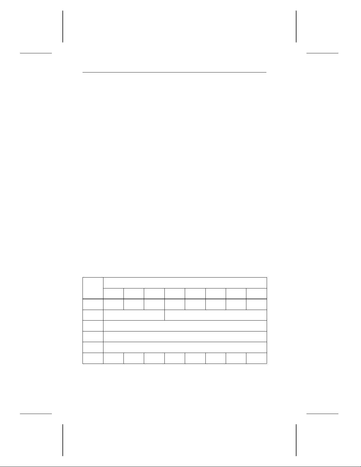
Bytes
7 6 5 4 3 2 1 0
Bits
0 0 0 0 0 1 0 0 0
1 LUN Logical block address (MSB)
2 Logical block address
3 Logical block address (LSB)
4 Transfer length
5 Control byte (00
)
H
Bytes 1–3 The
the read begins.
Byte 4 The
logical blocks of data to be transferred. A transfer length
of 0 indicates that 256 logical blocks are to be transferred.
Any other value indicates the number of logical blocks to be
transferred.
logical block address
transfer length
specifies the number of contiguous
specifies the logical block where
Page 49
40 Decathlon Family Product Manual, Rev. B
3.4.7 Write command (0AH)
When the drive receives the Write command, it writes the initiator’s data
to the disc. The drive receives all the write data before seeking or
disconnecting.
The AWRE bit of the Error Recovery page (01
) determines how the
H
drive handles bad sectors during a Write command. The Error Recovery
page is discussed in Appendix C.1.
If the system supports disconnection, the drive can disconnect and
reconnect while executing this command. The drive disconnects when
any of the following conditions arise:
• An internal error recovery procedure is required.
• The data transfer with the initiator is interrupted for more than 1 msec.
• The drive’s internal data buffer is full.
The buffer-empty ratio in the Disconnect/Reconnect page determines
when the drive reconnects. Section C.2 documents the Disconnect/Reconnect page.
The initiator must continue sending write data to the drive until the drive
sends a command complete status or until the initiator resets or aborts
the command.
If there is a reservation access conflict, this command terminates with a
reservation conflict status and no data is written. For more information
about the reservation conflict status, see Section 3.2.
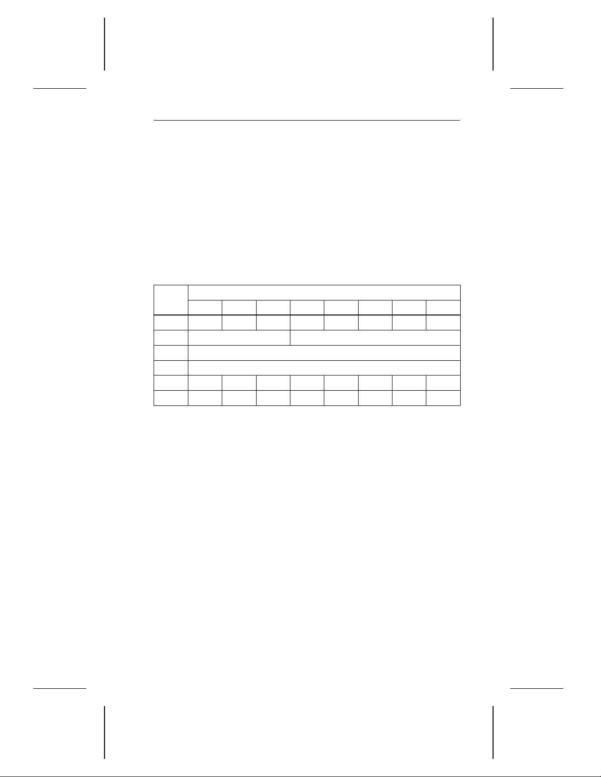
Bits
Bytes
7 6 5 4 3 2 1 0
0 0 0 0 0 1 0 1 0
1 LUN Logical block address (MSB)
2 Logical block address
3 Logical block address (LSB)
4 Transfer Length
5 0 0 0 0 0 0 Flag Link
Bytes 1–3 The
logical block address
specifies the logical block where
the write operation begins.
Page 50
Decathlon Family Product Manual, Rev. B 41
Byte 4 The
transfer length
blocks of data to be transferred. A transfer length of zero
indicates that 256 logical blocks are to be transferred. Any other
value indicates the number of logical blocks to be transferred.
specifies the number of contiguous logical
3.4.8 Seek command (0BH)
When the drive receives the Seek command, it seeks the specified logical
block address. This command is seldom used because all commands
that access the disc contain implied seeks. In systems that support
disconnection, the drive disconnects when it receives a valid Seek
command.
Bytes
0 0 0 0 0 1 0 1 1
1 LUN Logical block address (MSB)
2 Logical block address
3 Logical block address (LSB)
4 0 0 0 0 0 0 0 0
5 0 0 0 0 0 0 Flag Link
Bytes 1–3 The
7 6 5 4 3 2 1 0
logical block address
head seeks. For the maximum
may be specified for a Seek command, see Section 3.5.1.
Bits
specifies the logical block the
logical block address
that
3.4.9 Inquiry command (12H)
When the drive receives the Inquiry command, it asserts the data-in
phase and sends 68 bytes of inquiry data to the initiator. When the
requested inquiry data cannot be returned, a check condition status is
reported. After the data has been transferred to the initiator, the drive
deasserts the data-in phase.
If an Inquiry command is received from an initiator with a pending
unit-attention condition (before the drive reports a check condition
status), the drive performs the Inquiry command and the Unit Attention
condition is not cleared.
The initiator should allocate 36
returned to the initiator is summarized in Appendix D.
bytes for inquiry data. The inquiry data
H
Page 51
42 Decathlon Family Product Manual, Rev. B
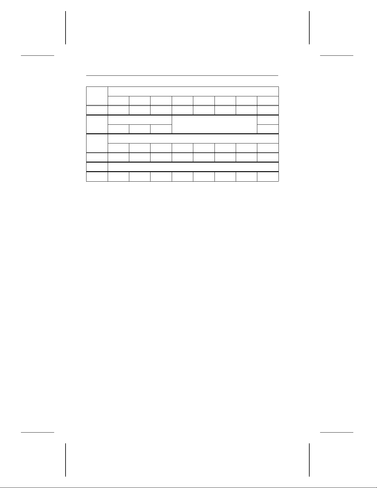
Bytes
0 0 0 0 1 0 0 1 0
1
2
3 0 0 0 0 0 0 0 0
4 Allocation length, in bytes
5 0 0 0 0 0 0 Flag Link
Byte 1 If the
Byte 2 The
Byte 4 The
7 6 5 4 3 2 1 0
LUN
0 0 0 0
0 0 0 0 0 0 0 0
enable vital product data (EVPD
returns the standard inquiry data. If the EVPD bit is one, the drive
returns the optional vital product data specified in byte 2.
page code
information the drive returns.
allocation length
has allocated for returned inquiry data. An allocation length of 0
indicates that no inquiry data is transferred. This condition is not
considered an error. Any other value indicates the maximum
number of bytes to be transferred. The allocation length should
be at least 36
data.
field specifies which page of the vital product
specifies the number of bytes the initiator
to allow the initiator to receive all of the inquiry
H
Bits
Reserved
Page code
) bit is zero, the drive
EVPD
3.4.10 Mode Select command (15H)
The Mode Select command allows the initiator to change parameters
stored in the mode pages. The mode pages are described in Appendix C.
The drive stores four copies of each mode page:
• Current values copy. This copy contains the parameter values the
drive uses to control its operation. After a power-on reset, hard reset
or bus device reset, the current values are equal to the saved values
if the saved values can be retrieved, or the default values if the saved
values cannot be retrieved.
• Changeable values copy. This copy does not actually contain any
parameters. Instead, it contains a map of each mode page indicating
which parameters are changeable by the initiator. If a bit contains a 1,
the corresponding value in the mode page is changeable. If a bit
contains a 0, the corresponding value in the mode page is not
changeable. The changeability values for each bit of each mode page
are listed in Appendix C with the default values.
Page 52
Decathlon Family Product Manual, Rev. B 43
• Default values copy. This copy contains the parameter values the
drive used as its current values when it was manufactured. The drive
defaults to these values after a reset condition, unless valid saved
values are available. The default values are listed in Appendix C.
• Saved values copy. The saved values are the values the drive stores.
If the parameter is changeable, these values can be set using a Mode
Select command. If the parameter is not changeable, the default
values are always used.
The drive has one set of mode parameters for all of the initiators on the
SCSI bus. If the initiator that issued the Mode Select command changes
a parameter that applies to another initiator, the drive generates a sense
key of
changed
sense codes are discussed in Appendix B.
Before sending any Mode Select commands, the initiator should send a
Mode Sense command requesting that the drive return all pages with
changeable values. The initiator uses this information to determine which
pages are supported, the proper length for those pages and which
parameters in those pages can be changed for that logical unit.
When the drive receives the Mode Select command, it updates the
savable parameters with the current values included in the Mode Select
command. After the drive saves the parameters, it reports a good status.
The drive verifies only Mode Select data that is defined as changeable.
unit attention
(26H) for all the other initiators. The sense keys and additional
with an additional sense of
mode parameters
If the drive detects invalid parameter data during the Mode Select
command, the drive sends a sense key of
additional sense code of
are changed.
Bytes
0 0 0 0 1 0 1 0 1
1 LUN PF = 1 0 0 0 SP
2 0 0 0 0 0 0 0 0
3 0 0 0 0 0 0 0 0
4 Parameter list length
5 0 0 0 0 0 0 Flag Link
Byte 1 The
7 6 5 4 3 2 1 0
page format (PF)
sent by the initiator after the mode select header and block
descriptors complies with the page format.
invalid field in parameter list
Bits
bit is always one. This means that the data
illegal request
and no parameters
with an
Page 53

44 Decathlon Family Product Manual, Rev. B
When the
pages in RAM and in nonvolatile memory.
When the
pages in RAM only, which means that the parameters are lost
when the drive is powered down.
When the drive executes the Mode Select command, it does not
save the Format Device page (03
page (04
mand.
Byte 4 The
header and mode page transferred to the drive. A parameter list
length of 0 means that no data is transferred. To calculate the
parameter list length for any given mode page, add the parameter list header (4 bytes), the block descriptor (if any, 8 bytes), the
2-byte mode page header and the length of the mode page. For
the lengths of the mode pages, refer to Appendix C.
save pages (SP)
save pages (SP)
); it saves these pages during the Format Unit com-
H
parameter list length
bit is 1, the drive saves the savable
bit is 0, the drive saves the savable
) and the Rigid Disc Geometry
H
specifies the length, in bytes, of the
Page 54

Decathlon Family Product Manual, Rev. B 45
3.4.10.1 Mode Select parameter list
The Mode Select parameter list contains a 4-byte header, followed by a
1-block descriptor (if any), followed by the pages of Mode Select parameters.
Each block descriptor specifies the media characteristics for all or part
of a logical unit. The rest of the Mode Select parameters are grouped by
function and organized into mode pages. The mode pages are described
in Appendix C.
Bytes
7 6 5 4 3 2 1 0
Bits
Parameter list header
0 (default) Reserved (00
1 (default) Medium type (00
2 (default) Reserved (00
3 (default) Block descriptor length (00
Block descriptor data
4 (default) Density code (00
5–7 Number of blocks
8 (default) Reserved (00
9–11 Block length
Parameter information
n
12–
Byte 1 The
medium type
Mode pages
field is always 00H, which means that the
drive is a direct-access device.
Byte 3 If the
block descriptor length
is sent to the drive. If the
is 8 bytes, a block descriptor
block descriptor length
no block descriptor is sent to the drive.
)
H
)
H
)
H
)
H
or 08H)
H
)
H
is 0 bytes,
Byte 4 The
Bytes 5–7 The
which is listed in the formatted capacity section of the
appropriate product manual.
Bytes 9–11 The
density code
is always 00H and cannot be changed.
number of blocks
block length
is always 0200H and cannot be changed.
is equal to the guaranteed sectors,
Page 55
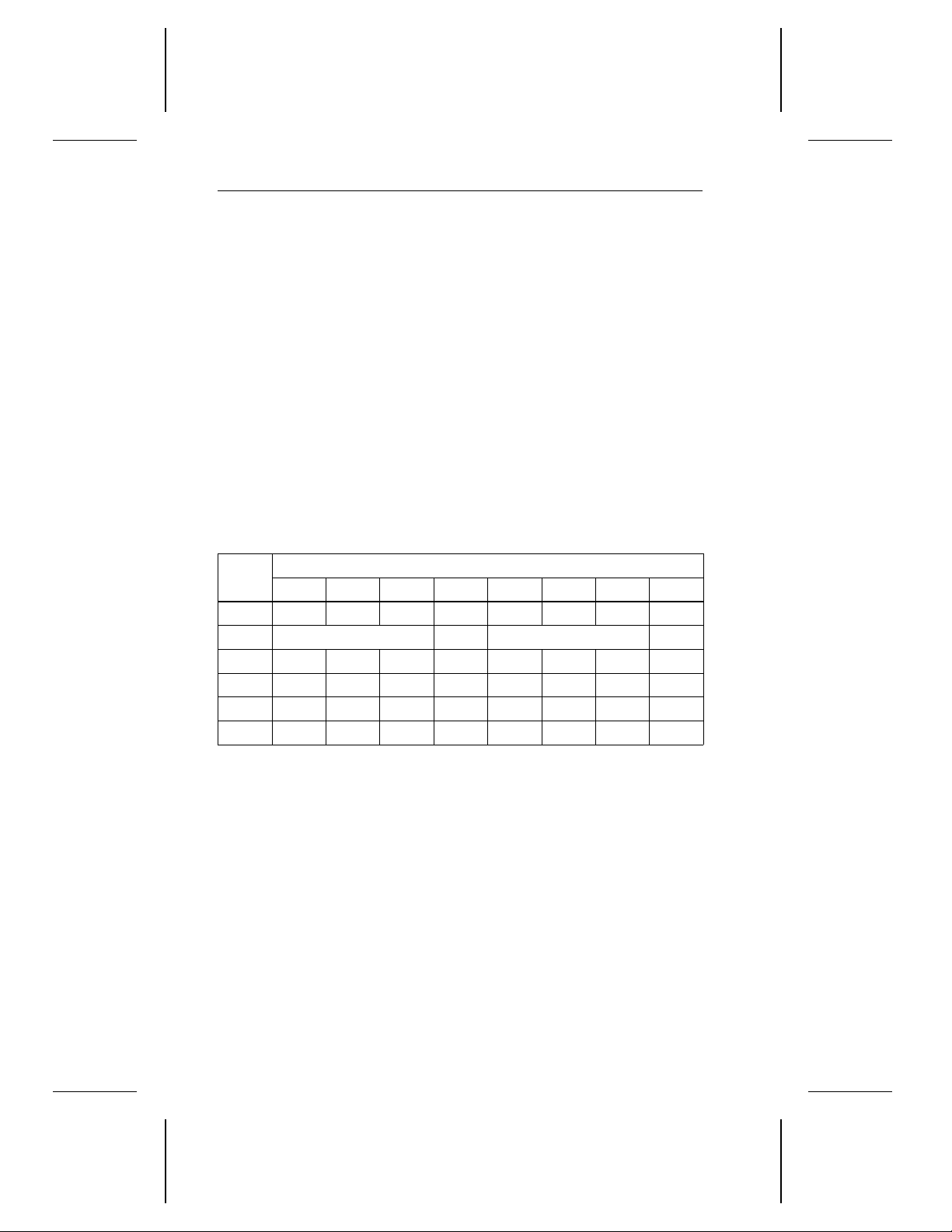
46 Decathlon Family Product Manual, Rev. B
3.4.11 Reserve command (16H)
When the initiator issues a Reserve command, it requests that the drive
be reserved for exclusive use by the initiator until the reservation is:
• Superseded by another Reserve command from the initiator that
made the reservation. An initiator that has already reserved the drive
can modify that reservation by issuing another Reserve command.
When the drive receives the superseding Reserve command, the
previous reservation is canceled.
• Released by a Release command from the same initiator. See the
Release command in Section 3.4.12.
• Released by a bus device reset message from any initiator
• Released by a hard reset
After the drive honors the reservation from one initiator, it accepts only
Request Sense and Inquiry commands from other initiators; the drive
rejects all other commands with a reservation conflict status.
Bytes
0 0 0 0 1 0 1 1 0
1 LUN 3rd pty 3rd party device ID Extent
2 0 0 0 0 0 0 0 0
3 0 0 0 0 0 0 0 0
4 0 0 0 0 0 0 0 0
5 0 0 0 0 0 0 Flag Link
Byte 1 If the
7 6 5 4 3 2 1 0
3rd pty
the 3rd pty bit is 1, the initiator reserves the drive for another
initiator. The SCSI ID of the third-party initiator is specified in the
3rd party device ID
extent
The
extent reservations. If the extent bit is 1, the drive generates a
check condition status.
bit is 0, the initiator reserves the drive for itself. If
field.
bit must always be 0. The drive does not support
Bits
Page 56
Decathlon Family Product Manual, Rev. B 47
3.4.12 Release command (17H)
When an initiator that had reserved the drive using the Reserve command issues the Release command, it cancels the reservation. If the
drive is not currently reserved and it receives a Release command, the
drive returns a good status.
Bytes
0 0 0 0 1 0 1 1 1
1 LUN 3rd pty 3rd party device ID Extent
2 0 0 0 0 0 0 0 0
3 0 0 0 0 0 0 0 0
4 0 0 0 0 0 0 0 0
5 0 0 0 0 0 0 Flag Link
Byte 1 If the
7 6 5 4 3 2 1 0
3rd pty
the 3rd pty bit is 1, the initiator releases the drive for another
initiator. An initiator can only release a third-party reservation
that it made. The SCSI ID of the third-party initiator is specified
in the
extent
The
extent reservations. If the extent bit is 1, the drive generates a
check condition status.
bit is 0, the initiator releases its own reservation. If
3rd party device ID
bit must always be 0. The drive does not support
Bits
field.
Page 57
48 Decathlon Family Product Manual, Rev. B
3.4.13 Mode Sense command (1AH)
When the initiator sends this command to the drive, it returns mode-page
parameters to the initiator. This command is used in conjunction with the
Mode Select command.
Bytes
0 0 0 0 1 1 0 1 0
1 LUN 0 0 0 0 0
2 PCF Page code
3 0 0 0 0 0 0 0 0
4 Allocation length
5 0 0 0 0 0 0 Flag Link
Byte 2 The
Byte 4 The
7 6 5 4 3 2 1 0
page control field (PCF)
Parameter bytes. Regardless of the value of the PCF, the block
descriptor always contains the current values.
PCF bit 7 PCF bit 6
0 0 Return current values.
0 1
1 0 Return default values.
1 1 Return saved values.
The
page code
The page codes are listed in Section 3.4.13.1.
allocation length
initiator has allocated for returned Mode Sense data. An allocation length of 0 means that no Mode Sense data is to be
transferred. This condition is not considered an error. Any other
value represents the number of bytes to be transferred. For a
description of the allocation length, see Section 3.4.13.1.
is the designator that is unique to each page.
specifies the number of bytes that the
Bits
determines the content of Mode
Effect
Return changeable values.
Page 58

Decathlon Family Product Manual, Rev. B 49
3.4.13.1 Page code and allocation length
The Mode Sense command descriptor block contains a page code
(byte 2, bits 5–0) and an allocation length (byte 4). These parameters
are described in the following table. You can transfer mode pages to the
initiator either of two ways:
• Transfer all mode pages at once by using page code 3F
, as de-
H
scribed in the last row of this table, or
• Transfer one mode page at a time by using the page code and
allocation length or any number greater than the allocation length of
the mode page.
Page
code
Allocation
length
Mode Sense data returned
4 bytes of Mode Sense header
01
H
18
8 bytes of block descriptor
H
2 bytes of mode-page header
10 bytes of Error Recovery parameters
4 bytes of Mode Sense header
02
H
18
8 bytes of block descriptor
H
2 bytes of mode-page header
12 bytes of Disconnect/Reconnect parameters
4 bytes of Mode Sense header
03
H
24
8 bytes of block descriptor
H
2 bytes of mode-page header
24 bytes of Format Device parameters
4 bytes of Mode Sense header
04
H
20
8 bytes of block descriptor
H
2 bytes of mode-page header
20 bytes of Rigid Disc Geometry parameters
4 bytes of Mode Sense header
08
H
20H
8 bytes of block descriptor
2 bytes of mode-page header
20 bytes of Caching parameters
4 bytes of Mode Sense header
0C
H
24
8 bytes of block descriptor
H
2 bytes of mode-page header
24 bytes of Notch and Partition parameters
continued
Page 59
50 Decathlon Family Product Manual, Rev. B
continued from previous page
Page
code
Allocation
length
Mode Sense data returned
4 bytes of Mode Sense header
0D
H
18
8 bytes of block descriptor
H
2 bytes of mode-page header
12 bytes of Power Condition parameters
4 bytes of Mode Sense header
38
H
1C
8 bytes of block descriptor
H
2 bytes of mode-page header
16 bytes of Cache Control parameters
4 bytes of Mode Sense header
3C
H
0FH
8 bytes of block descriptor
2 bytes of mode-page header
3 bytes of Soft ID parameters
4 bytes of Mode Sense header
00
*
H
10
8 bytes of block descriptor
H
2 bytes of mode-page header
4 bytes of Operating parameters
4 bytes of Mode Sense header
8 bytes of block descriptor
3F
H
143 or 144
2 bytes of mode-page header
143 or 144 bytes of mode parameters,
including all mode pages
* The allocation length depends on whether the Operating page has 2
or 3 bytes. The Operating page is described in Appendix C.10.
Page 60
Decathlon Family Product Manual, Rev. B 51
3.4.13.2 Mode Sense data
The Mode Sense parameter list contains a 4-byte header followed by an
8-byte block descriptor (if any), followed by the mode pages. The header
and block descriptor are shown below. The mode pages are described
in Appendix C.
Bytes
7 6 5 4 3 2 1 0
Bits
0 Mode Sense data length
1 (default) Medium type (00
2 WP=0 Reserved
3 (default) Block descriptor length (08
Block descriptor
4 (default) Density code (00
5–7 Number of blocks
8 (default) Reserved (00
H
9–11 Block length
Mode pages
n
12–
Byte 0 The
Mode Sense data length
Mode pages
specifies the number of
bytes minus 1 of the Mode Sense data to be transferred
to the initiator.
Byte 1 The
Byte 2 The
medium type
is always 0.
WP (write protect)
bit is always 0, which means the
media is write-enabled.
)
H
)
H
)
H
)
Byte 3 The
block descriptor length
block descriptor. This value does not include the page
headers and mode pages that follow the block descriptor,
if any.
Byte 4 The
Bytes 5–7 The
density code
number of blocks
blocks available to the user, which is specified on page 1.
Byte 8 Reserved
Bytes 9–11 The
block length
in each logical block described by the block descriptor.
is the number of bytes in the
is not supported.
field contains the total number of
specifies the number of bytes contained
Page 61
52 Decathlon Family Product Manual, Rev. B
3.4.14 Start/Stop Unit command (1BH)
When the drive receives the Start/Stop Unit command, the drive either
spins up or spins down, depending on the setting of the start bit in byte 4.
If the host adapter supports disconnection, the drive disconnects when
it receives the Start/Stop Unit command and reconnects when it is up to
speed and ready.
Bytes
0 0 0 0 1 1 0 1 1
1 LUN = 0 0 0 0 0 Immed
2 0 0 0 0 0 0 0 0
3 0 0 0 0 0 0 0 0
4 0 0 0 0 0 0 0 Start
5 0 0 0 0 0 0 Flag Link
Byte 1 If the
Byte 4 If the
7 6 5 4 3 2 1 0
immediate (Immed)
the command is completed. If the immed bit is 1, the drive returns
the status when it receives the command.
start
bit is 1, the drive spins up. If the
spins down.
Bits
bit is 0, the drive returns the status after
start
bit is 0, the drive
Page 62
Decathlon Family Product Manual, Rev. B 53
3.4.15 Receive Diagnostic Results command (1CH)
When the drive receives the Receive Diagnostics command, it sends
eight diagnostic data bytes to the initiator. The initiator sends the Receive
Diagnostic Results command after the drive completes the Send Diagnostic command, which is discussed in Section 3.4.16.
Bytes
0 0 0 0 1 1 1 0 0
1 LUN = 0 0 0 0 0 0
2 0 0 0 0 0 0 0 0
3–4 Allocation length
5 0 0 0 0 0 0 Flag Link
Bytes 3–4 The
7 6 5 4 3 2 1 0
allocation length
initiator has allocated for returned diagnostic result data. An
allocation length of 0 means that no diagnostic data is
transferred. Any other value indicates the maximum number of bytes to be transferred. The allocation length should
be at least 8 bytes to accommodate all the diagnostic data.
Bits
specifies the number of bytes the
Page 63
54 Decathlon Family Product Manual, Rev. B
3.4.15.1 Diagnostic data format
Bytes
7 6 5 4 3 2 1 0
0–1 (default) Additional length (0006
Bits
)
H
2–5 FRU code
6 Diagnostic error code
7 Vendor-unique error code
Byte 0–1 The
additional length
value indicates the number of additional bytes included in the diagnostic data list. A value of
0000
means that there are no additional bytes. A value of
H
0006
means that no product-unique bytes are available.
H
Bytes 2–5 If the
FRU information. If the FRU code is 01
field replaceable unit (FRU)
code is 00H, there is no
, replace the drive.
H
Other values are drive-unique.
Byte 6 The
Byte 7 The
diagnostic error code
is not supported.
vendor-unique error codes
are listed in Section
3.4.15.2.
3.4.15.2 Diagnostic error codes
The following diagnostic error codes are reported in byte 7 of the
diagnostic data format in Section 3.4.15.1.
Error code Description
01
H
02
H
09
H
H EEPROM test error
44
80
H
81
H
Sequencer test error
Microprocessor RAM diagnostic error
Fatal hardware error during drive diagnostics
Buffer controller diagnostic error
Buffer RAM diagnostic error
Page 64
Decathlon Family Product Manual, Rev. B 55
3.4.16 Send Diagnostic command (1DH)
When the drive receives this command, it performs diagnostic tests on
itself. In systems that support disconnection, the drive disconnects while
executing this command.
Bytes
0 0 0 0 1 1 1 0 1
1 LUN = 0 0 0
2 0 0 0 0 0 0 0 0
3–4 (default) Parameter list length (00
5 0 0 0 0 0 0 Flag Link
Byte 1 When the
Bytes 3–4 The
7 6 5 4 3 2 1 0
self test
diagnostics, which is the default self-test. If the default selftest is requested, the parameter list length is 0 and no data
is transferred. If the self-test passes successfully, the command terminates with a good status. If the self-test fails, the
command terminates with a check condition status and the
sense key is hardware error.
The
device off line (DevOfL)
unit off line (UnitOfL)
The
bit is 1, the drive performs the buffer RAM
parameter list length
supported.
Bits
Self
Test
)
H
bit is not supported.
bit is not supported.
must be zero. This byte is not
Dev
OfL
Unit
OfL
Page 65
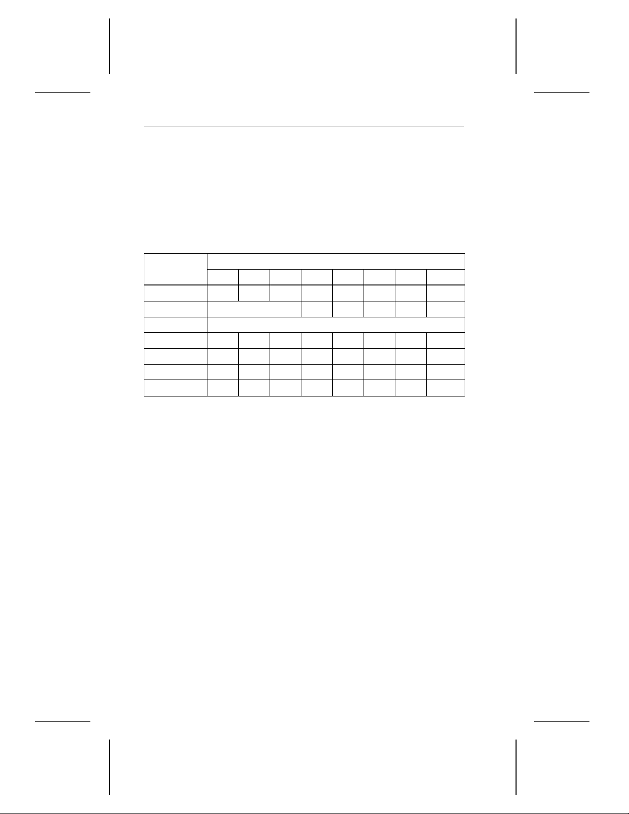
56 Decathlon Family Product Manual, Rev. B
3.5 Group 1 commands
3.5.1 Read Capacity command (25
The initiator uses the Read Capacity command to determine the capacity
of the drive. When the drive receives the Read Capacity command, it
sends the initiator read capacity data, which is described in Section 3.5.1.1.
Bytes
0 0 0 1 0 0 1 0 1
1 LUN 0 0 0 0 Rel Adr
2–5 Logical block address
6 0 0 0 0 0 0 0 0
7 0 0 0 0 0 0 0 0
8 0 0 0 0 0 0 0 PMI
9 0 0 0 0 0 0 Flag Link
Bytes 2–5 The
Byte 8 If the
7 6 5 4 3 2 1 0
logical block address
greater than the logical block address reported by the drive
in the read capacity data.
partial medium indicator (PMI)
block address in the CDB is also zero. The read capacity
data returned by the drive contains the logical block address
and block length of the last logical block of the drive.
Bits
specified in the CDB cannot be
)
H
bit is zero, the logical
If the PMI bit is one, the drive returns the read capacity data,
which contains the logical block address and block length
of the last logical block address, after which a substantial
delay (approximately 1 msec) in data transfer occurs. This
logical block address must be greater than or equal to the
logical block address specified in the CDB. This reported
logical block address is a cylinder boundary.
Page 66
Decathlon Family Product Manual, Rev. B 57
3.5.1.1 Read Capacity data
The Read Capacity data is shown below.
Bytes
0–3 Logical block address
4–7 Block length (00000200
Bytes 0–3 The logical block address is determined by the PMI bit in
Bytes 4–7 The block length is always 512.
7 6 5 4 3 2 1 0
the CDB of the Read Capacity command. The PMI bit is
described in Section 3.5.1.
Bits
)
H
3.5.2 Read Extended command (28H)
When the drive receives the Read Extended command, it transfers data
to the initiator. This command is the same as the Read command
discussed in Section 3.4.6, except that in the CDB for the Read Extended
command, a 4-byte logical block address and a 2-byte transfer length
can be specified.
If there is a reservation access conflict, this command terminates with a
reservation conflict status and no data is read. For more information
about the reservation conflict status, see Section 3.2.
Bytes
0 0 0 1 0 1 0 0 0
1 LUN DPO FUA 0 0 Rel Adr
2–5 Logical block address
6 0 0 0 0 0 0 0 0
7–8 Transfer length
9 0 0 0 0 0 0 Flag Link
7 6 5 4 3 2 1 0
Bits
Byte 1 If the
that the drive receives during this command has the lowest
priority for being retained in the cache. If the DPO is zero,
the cached data has the highest priority for being retained
in the cache.
disable page out (DPO)
bit is one, the cached data
Page 67

58 Decathlon Family Product Manual, Rev. B
If the
forced unit access (FUA)
access the disc to get the data requested by the initiator,
even if the data is available in the cache. If the FUA bit is
zero, the drive can get the data from the cache or the disc.
If the
RelAdr
bit is zero, the logical block address field
specifies the first logical block of the range of logical blocks
to be written and verified by the drive.
If the RelAdr bit is one, the logical block address field is a
two’s complement displacement. This displacement is
added to the logical block address last accessed on the
drive to determine the logical block address for this command.
Note. Set the RelAdr bit to one only if linked commands are
used.
bit is one, the drive must
Bytes 2–5 The
Bytes 7–8 The
logical block address
the read operation begins.
transfer length
logical blocks of data to be transferred. A transfer length
of 0 means that no logical blocks are to be transferred. This
condition is not considered an error. Any other value indicates the number of logical blocks to be transferred.
specifies the logical block where
specifies the number of contiguous
3.5.3 Write Extended command (2AH)
When the drive receives the Write Extended command, the drive writes
the data from the initiator to the disc. This command is like the Write
command, except that the CDB for this command contains a 4-byte
logical block address and a 2-byte transfer length. For more information
about the Write command, see Section 3.4.7.
If there is a reservation access conflict, this command terminates with a
reservation conflict status and no data is written. For more information
about the reservation conflict status, see Section 3.2.
Page 68
Decathlon Family Product Manual, Rev. B 59
Bytes
0 0 0 1 0 1 0 1 0
1 LUN DPO FUA 0 0 Rel Adr
2–5 Logical block address
6 0 0 0 0 0 0 0 0
7–8 Transfer length
9 0 0 0 0 0 0 Flag Link
Byte 1 If the
7 6 5 4 3 2 1 0
disable page out (DPO)
that the drive receives during this command has the lowest
priority for being retained in the cache. If the DPO is zero,
the cached data has the highest priority for being retained
in the cache.
If the
forced unit access (FUA)
access the disc to write the data sent by the initiator, even
if the data can be stored in the cache. If the FUA bit is zero,
the drive can write the data to the cache or the disc.
If the
RelAdr
specifies the first logical block of the range of logical blocks
to be written and verified by the drive.
If the RelAdr bit is one, the logical block address field is a
two’s complement displacement. This displacement is
added to the logical block address last accessed on the
drive to determine the logical block address for this command.
bit is zero, the logical block address field
Bits
bit is one, the cached data
bit is one, the drive must
Note. Set the RelAdr bit to one only if linked commands are
Bytes 2–5 The
the write operation begins.
Bytes 7–8 The
logical blocks of data to be transferred. A transfer length
of zero means that no logical blocks are to be transferred.
Any other value indicates the number of logical blocks to be
transferred.
used.
logical block address
transfer length
specifies the number of contiguous
specifies the logical block where
Page 69
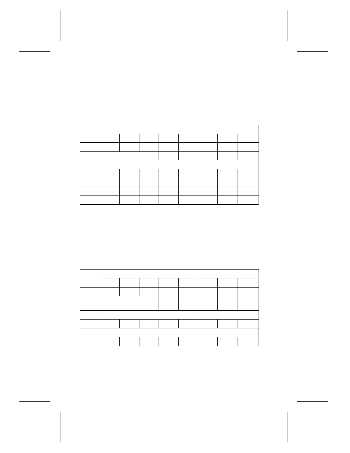
60 Decathlon Family Product Manual, Rev. B
3.5.4 Seek Extended command (2BH)
The Seek Extended command requests that the drive seek to the
specified logical block address. This command is the same as the Seek
command, except that the CDB includes a 4-byte logical block address.
The Seek command is described in Section 3.4.8.
Bytes
0 0 0 1 0 1 0 1 1
1 LUN 0 0 0 0 0
2–5 Logical block address
6 0 0 0 0 0 0 0 0
7 0 0 0 0 0 0 0 0
8 0 0 0 0 0 0 0 0
9 0 0 0 0 0 0 Flag Link
7 6 5 4 3 2 1 0
Bits
3.5.5 Write and Verify command (2EH)
When the drive receives the Write and Verify command, it writes the data
sent by the initiator to the media and then verifies that the data is correctly
written.
If the host adapter supports disconnection, the drive disconnects while
it is executing this command.
Bytes
0 0 0 1 0 1 1 1 0
1 LUN 0 0 0 BytChk
2–5 Logical block address
6 0 0 0 0 0 0 0 0
7–8 Transfer length
9 0 0 0 0 0 0 Flag Link
7 6 5 4 3 2 1 0
Bits
Rel
Adr
Byte 1 If the
media without performing a byte-by-byte comparison of the
data stored there. If the BytChk bit is one, the drive verifies
the media and performs a byte-by-byte comparison of the
data stored there.
byte check (BytChk)
bit is zero, the drive verifies the
Page 70

Decathlon Family Product Manual, Rev. B 61
If the
RelAdr
specifies the first logical block of the range of logical blocks
to be written and verified by the drive.
If the RelAdr bit is one, the logical block address field is a
two’s complement displacement. This displacement is
added to the logical block address last accessed on the
drive to determine the logical block address for this command.
Note. Set the RelAdr bit to one only if linked commands are
used.
bit is zero, the logical block address field
Bytes 2–5 The
where the drive begins writing and verifying the data.
Bytes 7–8 The
logical blocks to be transferred. If the transfer length is zero,
the initiator does not transfer any data and the drive does
not write or verify any data. This condition is not considered
an error.
logical block address
transfer length
field specifies the number of contiguous
field specifies the logical block
Page 71
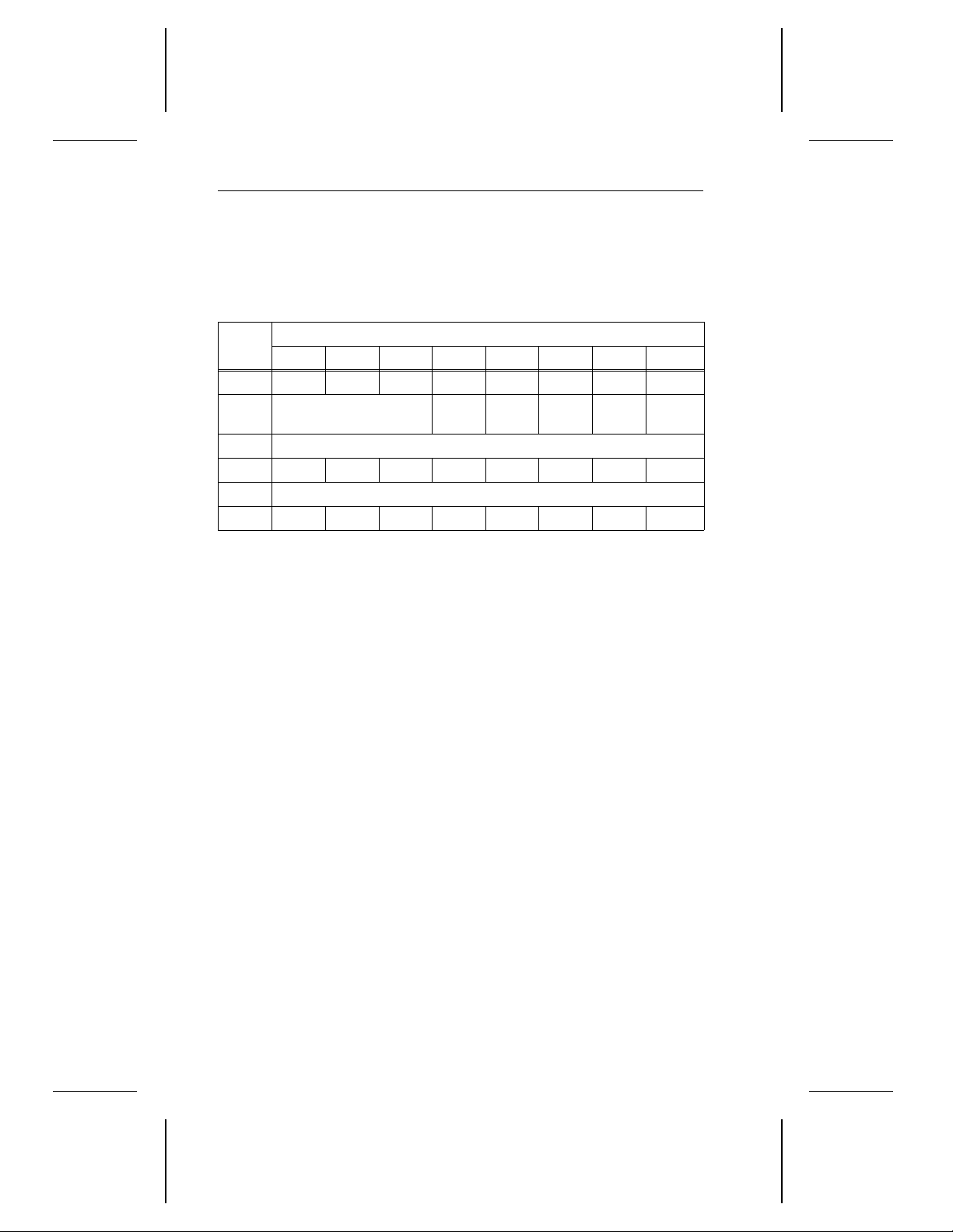
62 Decathlon Family Product Manual, Rev. B
3.5.6 Verify command (2FH)
When the drive receives the Verify command, it verifies the data on the
disc. If the host adapter supports disconnection, the drive disconnects
while it is executing this command.
Bytes
0 0 0 1 0 1 1 1 1
1 LUN 0 0 0
2–5 Logical block address
6 0 0 0 0 0 0 0 0
7–8 Verification Length
9 0 0 0 0 0 0 Flag Link
Byte 1 If the
7 6 5 4 3 2 1 0
byte check (BytChk)
media without performing a byte-by-byte comparison of the
stored data. If the BytChk bit is one, the drive verifies the
media and performs a byte-by-byte comparison of the
stored data.
A
RelAdr
field specifies the first logical block of the range of logical
blocks to be written by the drive.
If the RelAdr bit is one, the logical block address field is a
two’s complement displacement. This displacement is
added to the logical block address last accessed on the
drive to determine the logical block address for this command.
Note. Set the RelAdr bit to one only if linked commands are
bit of zero means that the logical block address
used.
Bits
Byt
Chk
bit is zero, the drive verifies the
Rel
Adr
Bytes 2–5 The
where the drive begins verifying the data.
Bytes 7–8 The
ous logical blocks to be verified. If the verification length is
zero, the drive does not verify any logical blocks, although
an implied seek is still performed. This condition is not
considered an error.
logical block address
verification length
field specifies the number of contigu-
field specifies the logical block
Page 72
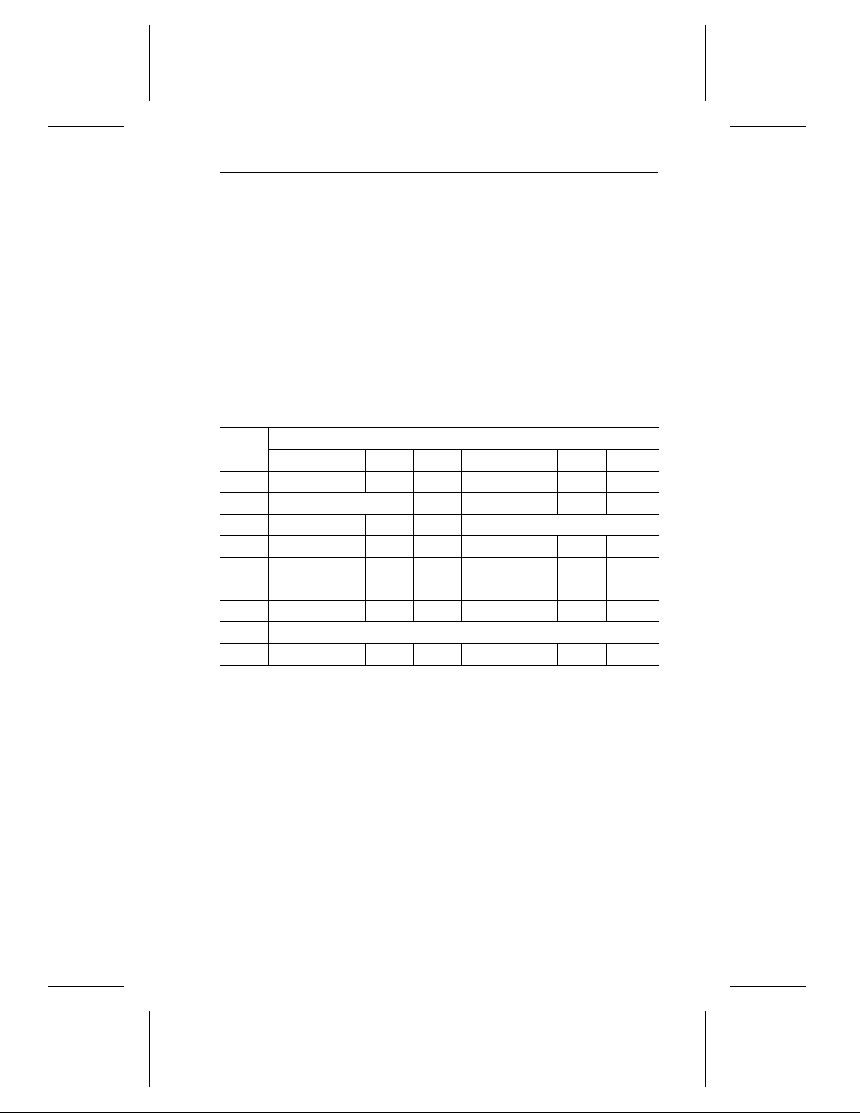
Decathlon Family Product Manual, Rev. B 63
3.5.7 Read Defect Data command (37H)
When the drive receives this command, it reads the defect data from
reserved cylinders or flash memory and transfers the defect data to the
initiator.
This command can be used in conjunction with the Format Unit command. Read Defect Data reads the defect lists off the reserved cylinders
or flash memory and resends the lists as defect data but does not change
the lists.
The Read Defect Data command can be used to access two types of
defect lists: the
primary defect list (PList)
These lists are described in Section 3.4.4.1.
and the
grown defect list (GList)
.
Bytes
7 6 5 4 3 2 1 0
Bits
0 0 0 1 1 0 1 1 1
1 LUN 0 0 0 0 0
2 0 0 0 PList GList Defect list format
3 0 0 0 0 0 0 0 0
4 0 0 0 0 0 0 0 0
5 0 0 0 0 0 0 0 0
6 0 0 0 0 0 0 0 0
7–8 Allocation length
9 0 0 0 0 0 0 Flag Link
Byte 2 If the
PList
bit is 1, the drive sends the primary defect list. If
the PList bit is 0, the drive does not send the primary defect
list.
If the
GList
bit is 1, the drive sends the grown defect list. If
the GList bit is 0, the drive does not send the grown defect
list.
If both the PList and GList bits are zero, the drive returns
the defect list header only.
If the
defect list format
field contains 100H, the drive returns
the defect data in the bytes-from-index format. If the defect
list format field contains 101
, the drive returns the defect
H
data in the physical sector format. If the defect list format
field contains 000
, the drive returns the defect data in the
H
default format, which is the physical sector format, and
generates a check condition status.
Page 73
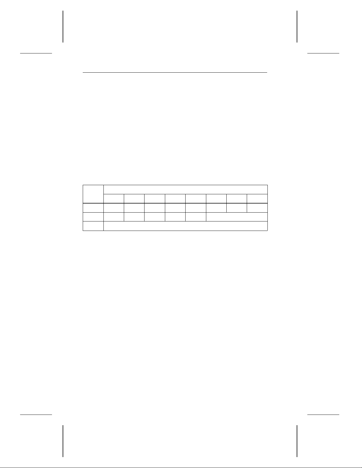
64 Decathlon Family Product Manual, Rev. B
Bytes 7–8 The
allocation length
initiator has allocated for the returned defect data. An
allocation length of 0 indicates that no defect data is transferred. Any other value indicates the maximum number of
bytes to be transferred. The data-in phase ends when the
allocation length bytes have been transferred or when all
available defect data has been transferred to the initiator,
whichever is less.
specifies the number of bytes the
3.5.7.1 Defect list header
The defect data always begins with a 4-byte header, followed by a 6-byte
descriptor for each defect. The defect list header format is described
below.
Bytes
0 0 0 0 0 0 0 0 0
1 0 0 0 PList GList Defect list format
2–3 Defect List Length
Byte 1 If the
7 6 5 4 3 2 1 0
PList
bit is 1, the defect data contains the primary
defect list. If the PList bit is 0, the defect data does not
contain the primary defect list.
Bits
If the
list. If the GList bit is 0, the defect data does not contain the
grown defect list.
The
Bytes 2–3 The
in bytes. If the PList and GList bits are 0, no defect descriptor bytes are sent to the initiator and the defect list length is
0. If the allocation length (in the CDB) is not large enough
to accommodate all the defect descriptors, the defect list
length contains the same value as the allocation length.
GList
bit is 1, the defect data contains the grown defect
defect list format
defect list length
field is described in Section 3.5.7.
specifies the length of the defect data
Page 74
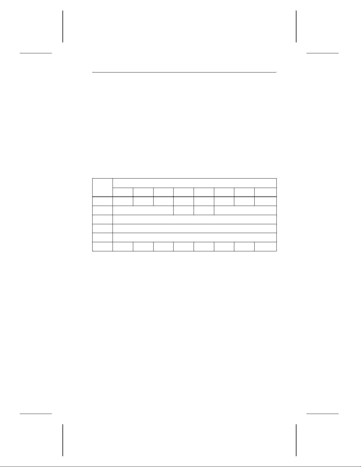
Decathlon Family Product Manual, Rev. B 65
3.5.8 Write Data Buffer command (3BH)
The Write Data Buffer command supports several different features.
The Write Data Buffer command can be used along with the Read Data
Buffer command to diagnose problems in the drive’s data buffer memory
and to test the integrity of the SCSI bus.
You can also use the Write Data Buffer command to download microcode
to the buffer and also to save it in flash memory.
Note. This command treats the buffer as a single segment, regardless
of the number of segments specified in Caching page 08
ing page 08
is described in Section C.5.3.)
H
. (Cach-
H
Bytes
7 6 5 4 3 2 1 0
Bits
0 0 0 1 1 1 0 1 1
1 LUN 0 0 Mode
2 Buffer ID (00
)
H
3–5 Buffer offset
6–8 Parameter list length
9 0 0 0 0 0 0 Flag Link
Byte 1 If the
mode
bits contain 000H, the initiator transfers data to the
drive buffer with a 4-byte header that contains all zeros. This
mode is called
mode
If the
drive buffer without the header. This mode is called
mode
If the
write combined header and data
.
bits contain 010H, the initiator transfers data to the
write data
bits contain 101H, the initiator downloads microcode
to the drive buffer, and the drive saves the microcode in flash
memory. The drive uses the new microcode for all future operations. This mode is called
Note. If the mode bits contain 101
download microcode and save
, the flag and link bits must
H
be 0.
After the microcode has been successfully downloaded, the
drive generates a unit attention condition of
downloaded
for all initiators except the one that issued the
microcode has been
current Write Data Buffer command.
.
.
All other settings for the mode bits are reserved.
Byte 2 The
buffer ID
is not supported and must always be zero.
Page 75
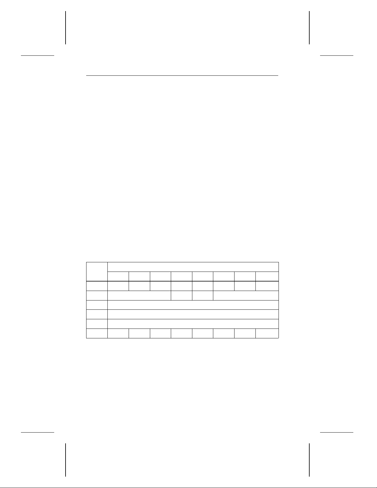
66 Decathlon Family Product Manual, Rev. B
Byte 3–5 The
buffer offset
is added to the starting address of the
buffer to determine the destination of the first data byte. The
bytes that follow are placed in sequential addresses. If the
sum of the buffer offset and the transfer length exceeds the
buffer size reported by the Read Data Buffer command (see
Section 3.5.9), the drive generates a check condition status
and the initiator does not transfer any data.
Bytes 6–8 The
parameter list length
field specifies the maximum number of bytes the initiator transfers. If the initiator transfers
the 4-byte header, the transfer length includes the header.
If the transfer length is zero, no data is transferred to the
drive buffer; this is not considered an error.
3.5.9 Read Data Buffer command (3CH)
The Read Data Buffer command supports several different features.
The Read Data Buffer command can be used along with the Write Data
Buffer command to diagnose problems in the drive’s data buffer memory
and to test the integrity of the SCSI bus.
Note. This command treats the buffer as a single segment, regardless
of the number of segments specified in mode page (08
page (08
Bytes
), the Caching page, is described in Section C.5.3.)
H
Bits
7 6 5 4 3 2 1 0
0 0 0 1 1 1 1 0 0
1 LUN 0 0 Mode
2 Buffer ID (00
)
H
3–5 Buffer offset
6–8 Allocation length
9 0 0 0 0 0 0 Flag Link
). (Mode
H
Byte 1 If the
drive buffer. The data is preceded by a 4-byte header. This mode
is called
If the
drive buffer without a header. This mode is called
All other settings for the mode bits are reserved.
Byte 2 The
mode
bits contain 000H, the initiator reads data from the
read combined header and data
mode
bits contain 010H, the initiator reads data from the
buffer ID
is not supported and must always be zero.
.
read data
.
Page 76
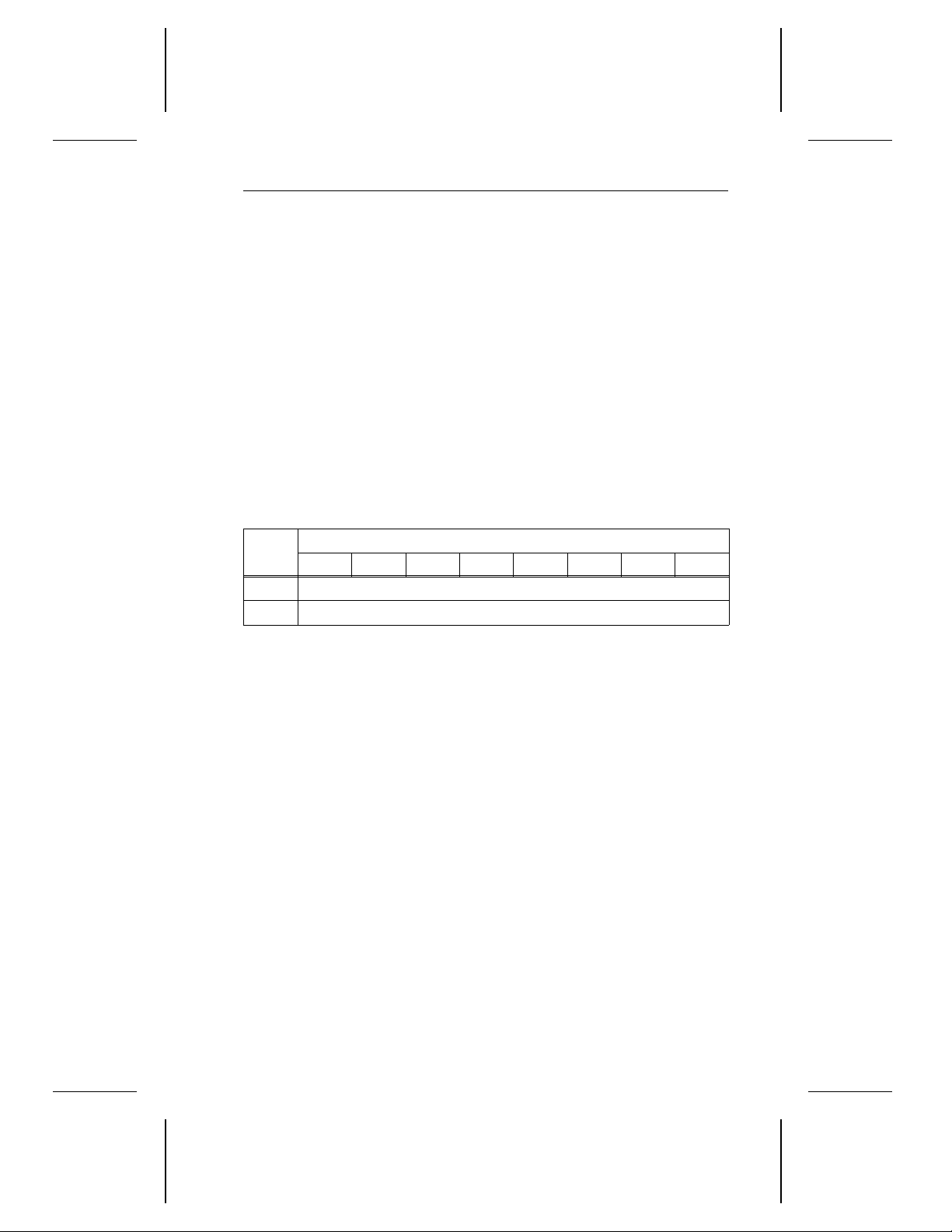
Decathlon Family Product Manual, Rev. B 67
Byte 3–5 The
Bytes 6–8 The
buffer offset
buffer to determine the source of the first data byte. The
bytes that follow are read from sequential addresses. If the
sum of the buffer offset and the transfer length exceeds the
available length reported in the Read Buffer header (see
Section 3.5.9.1), the drive transfers all the data contained
in the buffer.
allocation length
of bytes read by the initiator. If the 4-byte header is transferred, the transfer length includes the header. If the transfer
length is zero, no data is read; this is not considered an
error.
is added to the starting address of the
field specifies the maximum number
3.5.9.1 Read Buffer Header
The following table shows the structure of the 4-byte Read Buffer Header.
Bytes
0 0
1–3 Buffer capacity
Bytes 1–3 The
7 6 5 4 3 2 1 0
buffer capacity
buffer. Byte 1 is MSB; byte 3 is LSB.
Bits
field specifies the size of the drive
Page 77
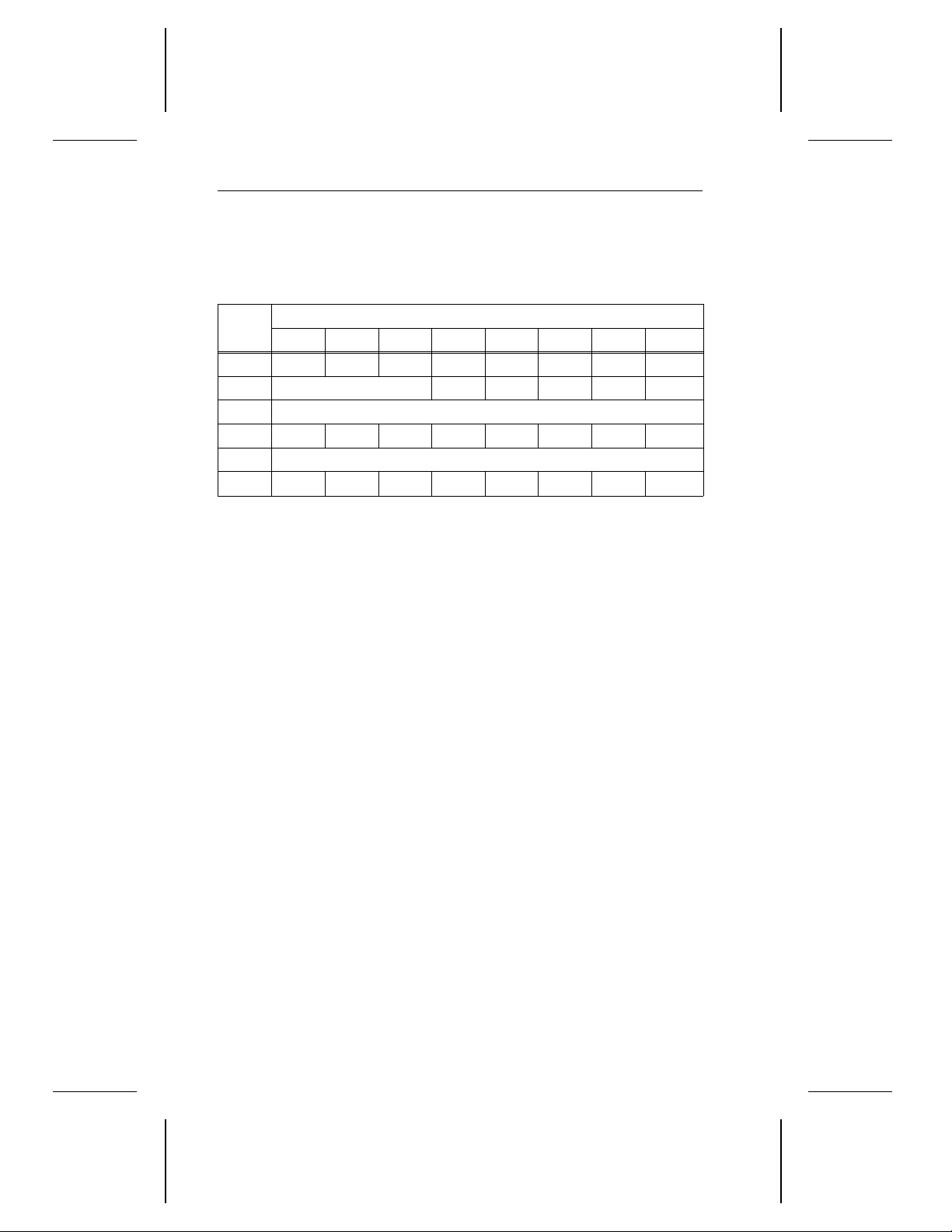
68 Decathlon Family Product Manual, Rev. B
3.5.10 Read Long command (3EH)
When the drive receives the Read Long command, it transfers data to
the initiator.
Bytes
0 0 0 1 1 1 1 1 0
1 LUN 0 0 0 0 0
2–5 Logical block address
6 0 0 0 0 0 0 0 0
7–8 Byte transfer length
9 0 0 0 0 0 0 Flag Link
Bytes 2–5 The
Bytes 7–8 The
7 6 5 4 3 2 1 0
logical block address
begins reading data.
byte transfer length
transferred to the initiator. The drive transfers the logical
block size plus eleven. If the byte transfer length is zero, the
drive does not transfer any data to the initiator. This condition is not considered an error.
Bits
specifies the LBA where the drive
specifies the number of bytes
Page 78
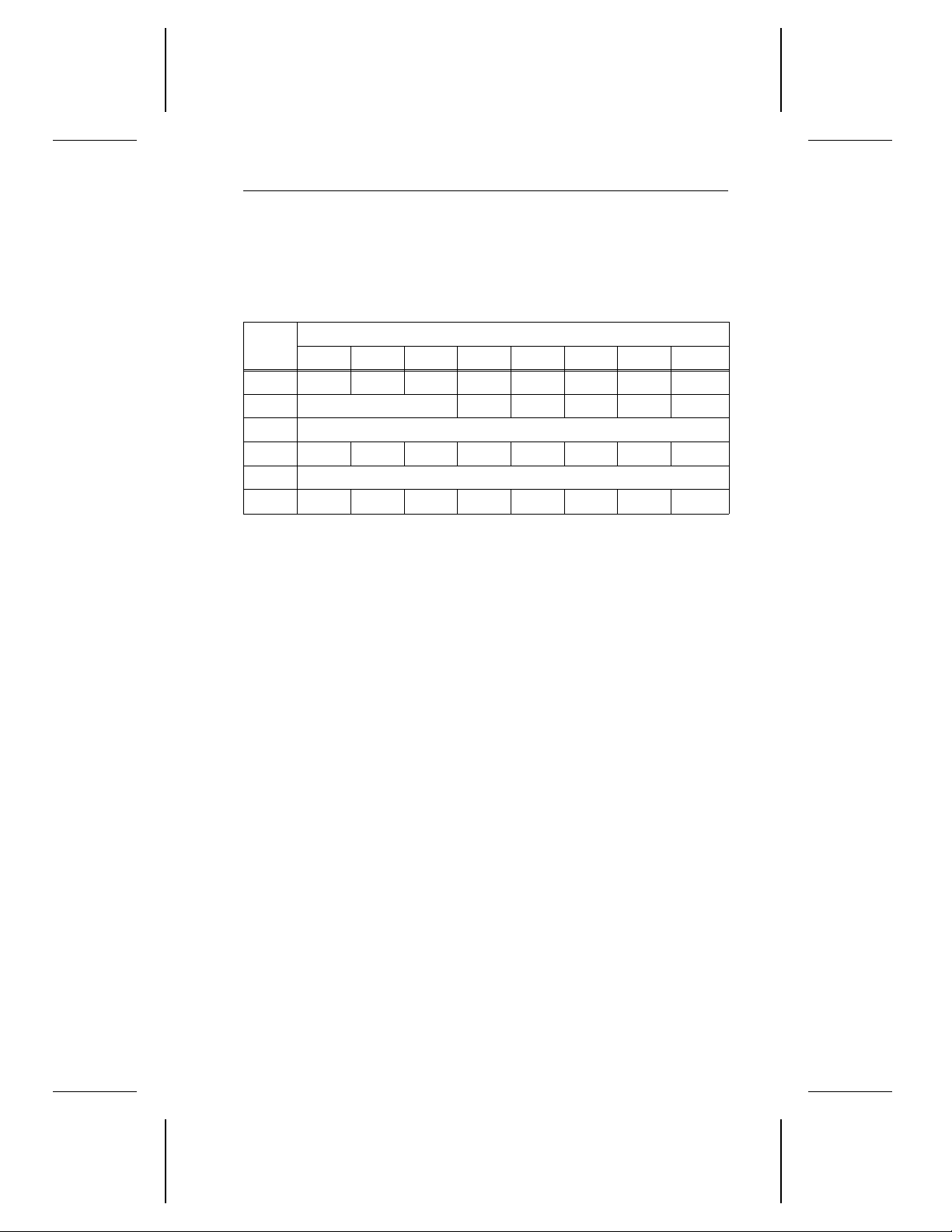
Decathlon Family Product Manual, Rev. B 69
3.5.11 Write Long command (3FH)
When the drive receives the Write Long command, it writes one logical
block of data and six bytes of error correction code (ECC) to the disc.
During this command, the drive does not perform any ECC verification.
Bytes
0 0 0 1 1 1 1 1 1
1 LUN 0 0 0 0 0
2–5 Logical block address
6 0 0 0 0 0 0 0 0
7–8 Byte transfer length
9 0 0 0 0 0 0 Flag Link
Bytes 2–5 The
Bytes 7–8 The
7 6 5 4 3 2 1 0
logical block address
begins writing data.
byte transfer length
initiator transfers to the drive.
If the transfer length does not equal the sum of the logical
block size plus eleven, the command is terminated with a
check condition status.
If the byte transfer length is zero, the initiator does not
transfer any data to the drive; this condition is not considered an error.
Bits
specifies the LBA where the drive
specifies the number of bytes the
Page 79

70 Decathlon Family Product Manual, Rev. B
3.6 Group 2, 3 and 4 commands
Group 2, 3 and 4 commands are 10-byte commands. Group 2 commands
are not implemented. Group 3 and 4 commands are reserved. If the drive
receives one of these commands, it returns a check condition status.
Caution. Do not use Group 3 and 4 commands. If you do, you may
destroy data on the disc.
3.7 Group 5 and 6 commands
Group 5 and 6 commands are 12-byte commands. Group 5 commands are
not implemented. If the drive receives a Group 5 command, it returns a check
condition status. Group 6 commands are reserved for Seagate use.
Caution. Do not use Group 6 commands. If you do, you may destroy
data on the disc.
3.8 Group 7 commands
Group 7 commands are 10-byte commands. These commands are not
implemented. If the drive receives one of these commands, it returns a
check condition status.
Page 80

Decathlon Family Product Manual, Rev. B 71
Appendix A. Supported messages
A.1 Single-byte messages
The implemented single-byte messages are listed below.
Must
Code Message name Direction
06
Abort O Yes
H
Abort tag O Yes
0D
H
Bus device reset O Yes
0C
H
Clear queue O Yes
0E
H
Command complete I —
00
H
Disconnect I —
04
H
Identify I/O No
80
H
Ignore wide residue I —
23
H
Initiate recovery I/O Yes
0F
H
Initiator detected error O Yes
05
H
Linked command complete
0A
H
Linked command complete
0B
H
I —
I —
(with flag)
09
Message parity error O Yes
H
Message reject I/O Yes
07
H
No operation O Yes
08
H
Head of queue tag O No
21
H
Ordered queue tag O No
22
H
Simple queue tag O No
20
H
Release recovery O Yes
10
H
Restore pointers I —
03
H
Save data pointer I —
02
H
Terminate I/O process O Yes
11
H
negate ATN
before last
ACK?
Page 81
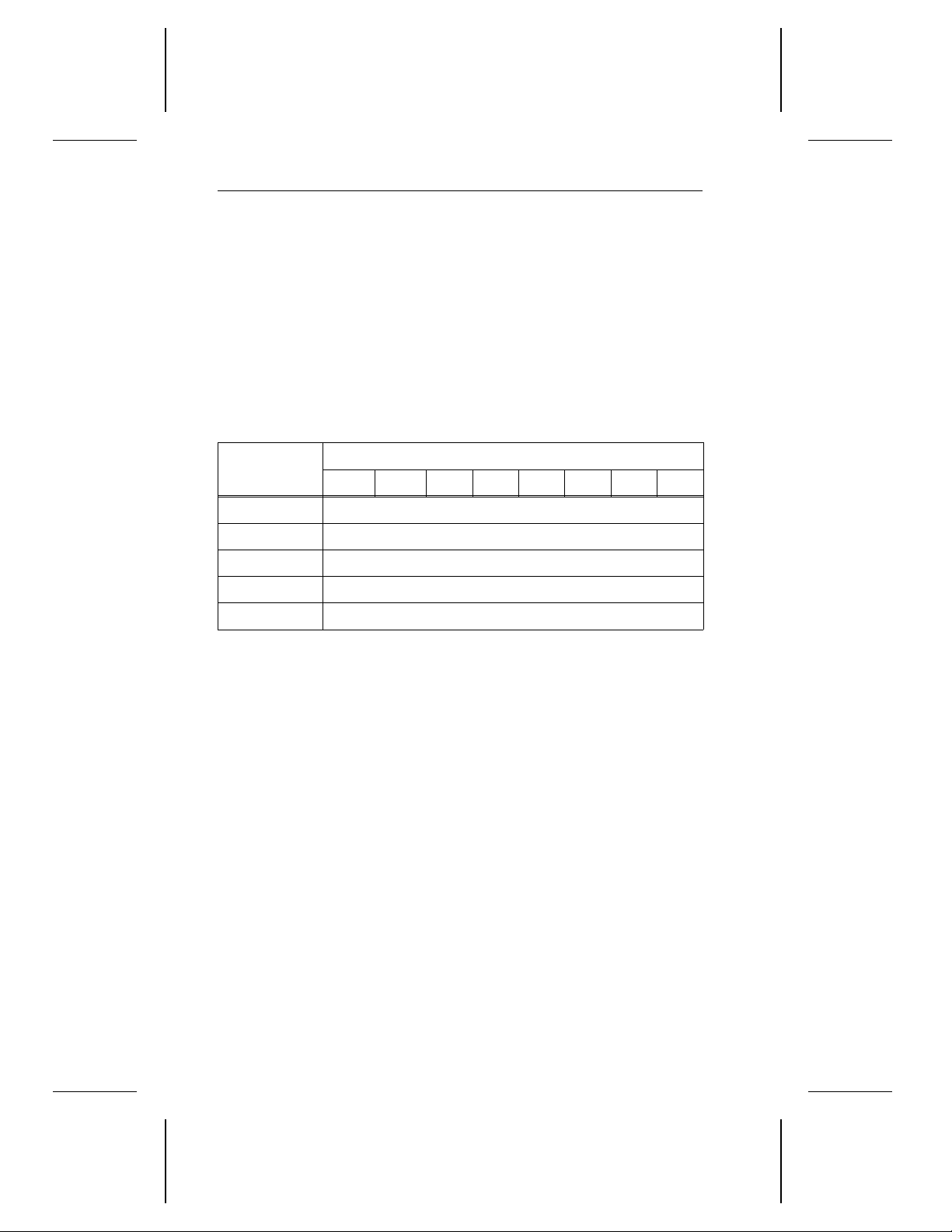
72 Decathlon Family Product Manual, Rev. B
A.2 Synchronous data transfer request message (01H)
The synchronous data transfer message is the only extended message
that the drive supports.
Depending on the value contained in the SSM bit (contained in byte 2 of
the Operating page in Appendix C.10), the drive or the initiator can
negotiate for synchronous data transfer after a reset. If any problem
precludes the successful exchange of synchronous data transfer request
messages, the initiator and drive default to asynchronous data transfers.
This exchange of messages establishes the transfer period and the
REQ/ACK offset.
Bytes
Bits
7 6 5 4 3 2 1 0
0 Extended message (01
1 Extended message length (03
2 Identifier code (01
)
H
)
H
)
H
3 Minimum transfer period divided by 4
4 REQ/ACK offset
Byte 0 This byte identifies the message as an extended message.
Byte 1 This byte reports the length of the message.
Byte 2 This byte identifies the message as a synchronous data transfer
request message.
Byte 3 The value contained in this byte is in nanoseconds. It is equal to
the minimum time between leading edges of successive REQ
and ACK pulses divided by four. In byte 3, the minimum value
supported by the drive is 25, which is equivalent to a transfer
period of 100 nanoseconds, or an external transfer rate of
10 Mbytes per second. A value of 50 is equivalent to a transfer
period of 200 nanoseconds, or an external transfer rate of
5 Mbytes per second.
Byte 4 The
REQ/ACK offset
is the maximum number of REQ pulses
that may be outstanding before its corresponding ACK pulse is
received at the target. A REQ/ACK offset of zero indicates
asynchronous mode. The drive supports a maximum REQ/ACK
offset of 0F
.
H
Page 82
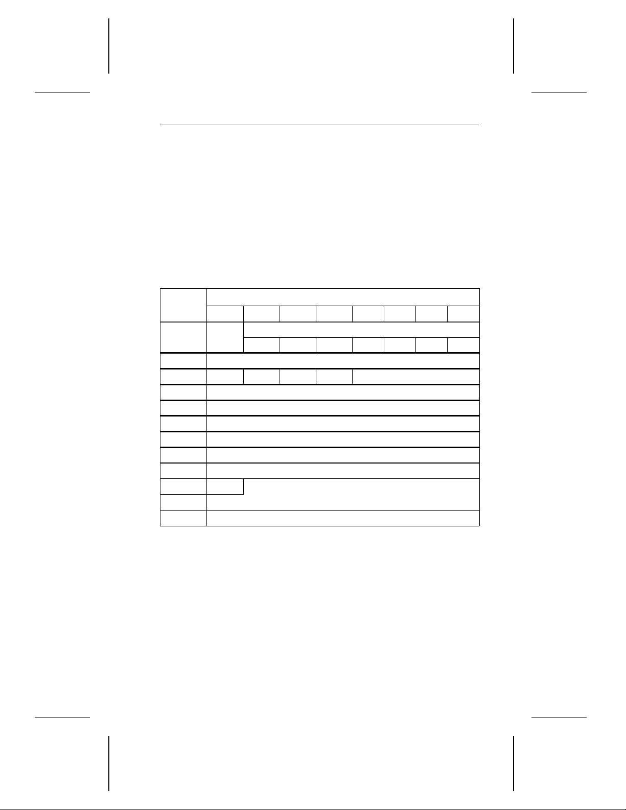
Decathlon Family Product Manual, Rev. B 73
Appendix B. Sense data
The appendix contains the descriptions for sense data returned by the
Request Sense command. For more information on the Request Sense
command, see the
, publication number 77738479-D.
sion 2
B.1 Additional sense data
When the initiator issues a Request Sense command, the drive returns
the following additional sense data.
Seagate SCSI-2/3 Interface Manual Volume 2; Ver-
Bytes
0 Valid
1 Segment number (00
2 0 0 ILI 0 Sense key
3–6 Information bytes
7 Additional sense length
8–11 Command specific data
12 Additional sense code
13 Additional sense code qualifier
14 FRU code
15 SKSV
16–17
18–22 Product-unique sense data (00
Byte 0 If the
7 6 5 4 3 2 1 0
1 1 1 0 0 0 X
Sense key specific
valid
bit is one, the information bytes (bytes 3 through 6)
are valid. If the valid bit is zero, the information bytes are not
valid.
If the
error code
the command that is currently pending. If the error code contains
a value of 71
previous command for which a good status has already been
returned.
contains a value of 70H, the error occurred on
, the error occurred during the execution of a
H
Bit
Error code
H
)
)
H
Byte 1 The
segment number
is always zero.
Page 83

74 Decathlon Family Product Manual, Rev. B
Byte 2 If the
incorrect length indicator (ILI)
bit is zero, the requested block of data from the previous command did not
match the logical block length of the data on the disc. If
the ILI bit is one, the requested block of data from the
previous command matched the logical block length of the
data on the disc.
The
sense key
indicates one of nine general error cate-
gories. These error categories are listed in Appendix B.2.
Bytes 3–6 When the
valid
bit is 1, the
information bytes
logical block address of the current logical block associated with the sense key. For example, if the sense key is
media error, the information bytes contain the logical
block address of the offending block.
Byte 7 The
additional sense length
0E
additional bytes. If the allocation length of the com-
H
is limited to a maximum of
mand descriptor block is too small to accommodate all of
the additional sense bytes, the additional sense length is
not adjusted to reflect the truncation.
Bytes 8–11 These bytes contain command-specific data.
Bytes 12–13 The
additional sense code
qualifier
provide additional details about errors. See Ap-
and
additional sense code
pendix B.3.
Byte 14 The
field replaceable unit (FRU) code
is used by field
service personnel only.
contain the
Bytes 15–22 These bytes are not used and are always 00
.
H
B.2 Sense key
The sense keys in the lower-order bits of byte 2 of the sense data returned
by the Request Sense command are described in the following table.
You can find a more detailed description of the error by checking the
additional sense code and the additional sense code qualifier in Section B.3.
Sense key Description
0
H
1
H
No Sense. In the case of a successful command, no
specific sense key information needs to be reported for
the drive.
Recovered error. The drive completed the last
command successfully with some recovery action.
When many recovered errors occur during one
command, the drive determines which error to report.
Page 84

Decathlon Family Product Manual, Rev. B 75
Sense key Description
2
H
Not ready. The addressed logical unit cannot be
accessed. Operator intervention may be required to
correct this condition.
3
H
Medium error. The command was terminated with a
nonrecoverable error condition, probably caused by a
flaw in the media or an error in the recorded data.
4
H
Hardware error. The drive detected a nonrecoverable
hardware failure while performing the command or
during a self-test. This includes, for example, SCSI
interface parity errors, controller failures and device
failures.
5
H
Illegal request. This indicates an illegal parameter in
the CDB or in the additional parameters supplied as
data for some commands (for example, the Format
Unit command, the Mode Sense command and
others). If the drive detects an invalid parameter in the
CDB, it terminates the command without altering the
media. If the drive detects an invalid parameter in the
additional parameters supplied as data, the drive may
have already altered the media.
6
H
Unit attention. The drive may have been reset. See
the
Seagate SCSI-2 Interface Manual
for more details
about the Unit Attention condition.
B
H
Aborted command. The drive aborted the command.
The initiator may be able to recover by retrying.
E
H
Miscompare. The source data did not match the data
read from the media.
Page 85

76 Decathlon Family Product Manual, Rev. B
B.3 Additional sense code and additional sense code
qualifier
The additional sense code and additional sense code qualifiers returned
in byte 12 and byte 13, respectively, of the Sense Data Format of the
Request Sense command are listed in the following table.
Error code (hex)
DescriptionByte 12 Byte 13
00 00 No additional information is supplied.
01 00 There is no index/sector signal.
02 00 There is no seek complete signal.
03 00 A write fault occurred.
04 00 The drive is not ready.
05 00
06 00 Track 0 was not found.
07 00 More than one drive is selected at a time.
08 00 There was a drive communication failure.
09 00 A track following error occurred.
0A 00 An error log overflow occurred.
0C 00
10 00 An ID CRC or ECC error occurred.
11 00 An unrecovered read error occurred.
12 00
13 00
14 00 No record was found.
14 01 No record was found.
15 00 A seek positioning error occurred.
16 00
17 01
18 01 The data was recovered with ECC.
18 02
The drive does not respond when it is selected.
A write error occurred.
The address mark was not found in the ID field.
The address mark was not found in the data
field.
A data address mark was recovered.
The data was recovered with retries.
The data was recovered and ARRE was
performed.
Page 86

Decathlon Family Product Manual, Rev. B 77
Error code (hex)
DescriptionByte 12 Byte 13
19 00
There is an error in the defect list.
1A 00
1B 00
1C 00
1C 01
1C 02
1D 00
1E 00
20 00
21 00
22 00
24 00
25 00
26 00
29 00
2A 01
2F 00
30 00
A parameter overrun occurred.
A synchronous transfer error occurred.
The defect list could not be found.
The primary defect list could not be found.
The grown defect list could not be found.
A miscompare occurred during a verify
operation.
An ID error was recovered.
The drive received an invalid command
operation code.
The logical block address was not within the
acceptable range.
The drive received a CDB that contains an
invalid bit. (This error code applies to direct-
access devices.)
The drive received a CDB that contains an
invalid bit. (This error code applies to all SCSI
devices.)
The drive received a CDB that contains an
invalid LUN.
The drive received a CDB that contains an
invalid field.
A power-on reset or a bus device reset
occurred.
The Mode Select parameters were changed
by another initiator.
The commands were cleared by another
initiator.
The medium is incompatible.
31 00
31 01
continued
The media format is corrupted.
The format command failed.
Page 87

78 Decathlon Family Product Manual, Rev. B
continued from previous page
Error code (hex)
DescriptionByte 12 Byte 13
32 00
There are no spare defect locations available.
37 00
3D 00
A rounded parameter caused an error.
The identify message contains invalid bits.
3F 00 The target operation command was changed.
3F 01 The microcode was changed.
40 00 There was a diagnostic failure.
A self-test error occurred (80-87 for tests 0-7).
40 8
40 88
40 89
x
Save RB failed during the reassignment of
blocks ARRE/AWRE.
Read RB failed during the reassignment of
blocks ARRE/AWRE.
40 90
40 Ax
40 A8
40 A9
A configuration error occurred.
A self-test error occurred (A1-AF for tests 1-F)
The flash memory cannot be read or written.
The flash memory directory cannot be read, or
it is corrupted.
40 AA
The flash memory contains an incompatible
version number.
40 AB
The flash memory contains an incompatible
revision number.
40 AC A flash memory checksum error occurred.
40 AD
40 AE
The flash memory contains invalid parameters.
The flash memory is incompatible with the
HDA and the circuit board. The flash memory
must be reconfigured.
40 AF SYNC/ASYNC discware was swapped.
40 B0 The servo command timed out.
40 B1 The servo command failed.
40 B2 The servo command was rejected.
40 B3 The servo interface does not work.
Page 88

Decathlon Family Product Manual, Rev. B 79
Error code (hex)
DescriptionByte 12 Byte 13
40 B4
40 B5
40 B6 During spinup, a servo error occurred.
40 B7 The servo pattern is inconsistent.
40 B8 A seek recovery error occurred.
40 B9
40 C0
The servo either failed to lock on track during
spinup or has wandered off track.
An internal servo error occurred.
The actuator did not achieve high-speed
calibration.
The defect list is full.
40 C1
40 C2
40 C3
40 C4
43 00 A message reject error occurred.
44 00 An internal controller error occurred.
45 00
47 00 A SCSI interface bus parity error occurred.
48 00 The initiator has detected an error.
49 00
4E 00
A failure occurred while the grown defect list
was being written.
The write life-cycle of the flash memory has
been exceeded.
There was an attempt to add an illegal entry to
the grown defect list.
There was an attempt to add a duplicate entry
to the grown defect list.
An error occurred during a selection or a
reselection.
The initiator received an invalid message from
the drive.
The drive attempted to perform overlapped
commands.
Page 89

Page 90

Decathlon Family Product Manual, Rev. B 81
Appendix C. Mode pages
Mode pages are groups of parameters stored by the drive. These
parameters can be read using the Mode Sense command and changed
using the Mode Select command. These commands are described in
Sections 3.4.10 and 3.4.13.
This appendix contains the default parameters and the changeable
parameters for the mode pages. The current parameters and the saved
parameters are not shown.
Note. The default values contained in this appendix may differ from the
default values actually contained in your drive. To determine the
default values, use the Mode Sense command.
Contains
changeable
Mode page Page code Bytes
Error Recovery page 01
Disconnect/Reconnect page 02
Format Device page 03
Rigid Disc Geometry page 04
Caching page (SCSI-3)
08
Control Mode page 0A
Notch page 0C
Cache Control page 38
Soft ID page 3C
Operating page 00
H
H
H
H
H
H
H
H
H
H
10 Yes
14 Yes
22 No
22 No
18 Yes
10 Yes
22 No
14 No
2 or 3 Yes
parameters
1 Yes
Page 91
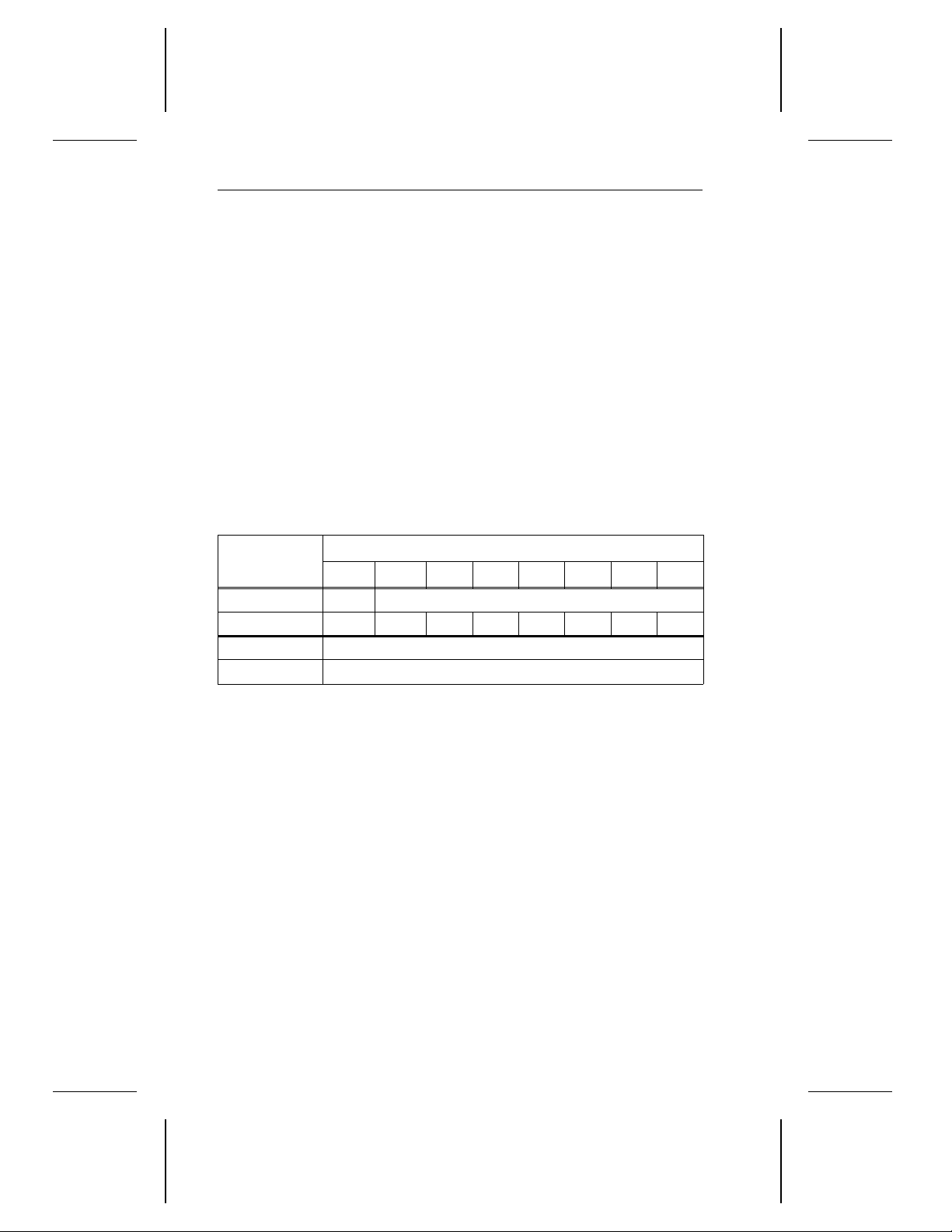
82 Decathlon Family Product Manual, Rev. B
For all mode pages:
• If the changeable value is 0, the initiator
If the changeable value is 1, the initiator
cannot
change the bit directly.
can
change the bit directly.
For example, in the header below, the changeable value for the page
code bits is 0, which means that the page code cannot be changed;
the changeable value of the PS bit is one, which means that the PS
bit can be changed.
• During the Mode Sense command, the PS (parameter savable) bit
is 1, which means the mode page is saved on the disc. During the
Mode Select command, you must set the PS bit to 0.
• An “X” means that the value of the bit cannot be specified. For
example, the default value of bit 0 of byte 1 of page 00
(the Operating
H
page) cannot be specified because the bit can be either 1 or 0.
All mode pages contain a 2-byte header that contains the page code and
the page length for that particular page. The header is shown below.
Bytes
Bits
7 6 5 4 3 2 1 0
0 PS Page code
changeable 1 0 0 0 0 0 0 0
1 Page length
changeable 00
H
Byte 0 During the Mode Sense command, the PS (parameter savable)
bit is 1, which means the mode page is saved on the disc. During
the Mode Select command, you must set the PS bit to 0.
The
Byte 1 The
page code
page length
is the unique code that identifies the page.
is the length, in bytes, of the page.
Page 92
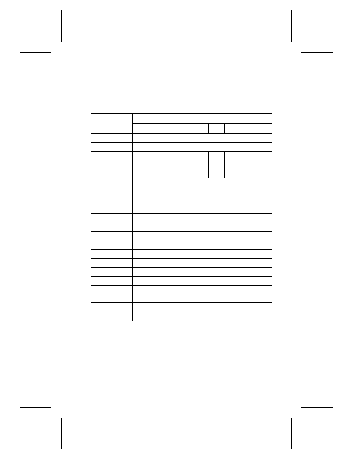
Decathlon Family Product Manual, Rev. B 83
C.1 Error Recovery page (01H)
The Error Recovery page is shown below. This table summarizes the
function, the default value and the changeability of each bit.
Bytes
Bits
7 6 5 4 3 2 1 0
0 PS (1) Page code (01
1 Page length (0A
)
H
)
H
2 AWRE ARRE TB RC EER PER DTE DCR
default 0 0 0 0 0 0 0 0
changeable 1 1 1 1 1 1 1 1
3 (default) Read retry count (20
changeable FF
H
)
H
4 (default) Correction span (16H)
changeable 00
H
5 (default) Head offset count (00H)
changeable 00
H
6 (default) Data strobe offset count (00H)
changeable 00
H
7 (default) Reserved (00H)
changeable 00
H
8 (default) Write retry count (20H)
changeable FF
H
9 (default) Reserved (00H)
changeable 00
H
10–11 (default) Recovery time limit (FFFFH)
changeable 0000
H
Page 93

84 Decathlon Family Product Manual, Rev. B
Byte 2 When the
the drive automatically reallocates bad blocks detected while
writing to the disc. When the AWRE bit is 0, the drive does not
perform automatic reallocation; instead, the drive reports a
check condition status with a sense key of media error.
Note. The AWRE bit does not apply during the Format com-
mand.
When the
the drive automatically reallocates bad blocks detected while
reading from the disc. When the ARRE bit is 0, the drive does
not automatically reallocate bad blocks. Instead, a check condition status is reported with a sense key of media error.
The
transfer block (TB)
When the
without doing any corrections. This function supersedes other
bits in this byte. When the RC bit is 0, the correction is performed
according to the other bits in this byte.
The
enable early recovery (EER)
post error (PER)
The
disable transfer on error (DTE)
The
When the
apply offline ECC to the data even if it can correct the data.
automatic write reallocation enabled (AWRE)
automatic read reallocation enabled (ARRE)
bit is not supported.
read continuous (RC)
bit is not supported.
disable correction (DCR)
bit is 1, the drive sends all data
bit is not supported.
bit is not supported.
bit is 1, the drive does not
bit is 1,
bit is 1,
Byte 3 The
Byte 4 The
Byte 5 The
Byte 6 The
Byte 7 Reserved
read retry count
drive attempts its recovery algorithms. The read retry count field
has a range of 0 through 20
correction span
bits, on which ECC correction is attempted. Longer errors are
reported as nonrecoverable.
head offset count
performed as part of the drive’s retry algorithms.
data strobe offset count
field is the maximum number of times the
.
H
is the size of the largest read data error, in
is not implemented. Head offsets are
is not implemented.
Page 94

Decathlon Family Product Manual, Rev. B 85
Byte 8 The
write retry count
field contains the maximum number
of times the drive attempts its recovery algorithms. This
byte is a reflection of byte 3 and is not directly changeable.
When mode selecting a change to this byte, the drive
responds with a good status and command complete
message.
Byte 9 Reserved
Bytes 10–11 The
recovery time limit
field always has a value of FFFFH,
which means that the recovery time is unlimited.
C.2 Disconnect/Reconnect page (02H)
The Disconnect/Reconnect page is shown below. This table summarizes
the function, the default value and the changeability of each bit.
Bytes
7 6 5 4 3 2 1 0
0 PS (1) Page code (02
1 Page length (0E
2 (default) Buffer full ratio (99
changeable FF
3 (default) Buffer empty ratio (99H)
changeable FF
4–5 (default) Bus inactivity limit (0000
changeable 0000
6–7 (default) Disconnect time limit (0000H)
changeable 0000
8–9 (default) Connect time limit (0000H)
changeable 0000
10–11 (default) Maximum burst size (0000H)
changeable 0000
12–15 (default) Reserved (00000000H)
changeable 00000000
Bits
)
H
)
H
)
H
H
H
)
H
H
H
H
H
H
Page 95

86 Decathlon Family Product Manual, Rev. B
Byte 2 The
how full the drive’s buffer is before reconnecting. The drive
rounds up to the nearest whole logical block. This parameter is the numerator of a fraction that has 256 as its
denominator.
Byte 3 The
mands, how empty the drive’s buffer is before reconnecting to fetch more data. The drive rounds up to the nearest
whole logical block. This parameter is the numerator of a
fraction that has 256 as its denominator.
Bytes 4–5 The
increments, that the drive can assert the Busy signal
without handshakes until it disconnects. The drive can
round down to its nearest capable value. If the bus inactivity limit is 0000
for 1 msec without handshakes.
Bytes 6–7 The
time, in 100-µsec increments, that the drive remains
disconnected until it attempts to reconnect. A value of 0
indicates that the drive is allowed to reconnect immediately.
Bytes 8–9 The
in 100-µsec increments, that the drive should remain
connected until it attempts to disconnect. The drive may
round to its nearest capable value. A value of 0 means
that the drive can remain connected indefinitely until it
tries to disconnect.
buffer full ratio
field indicates, on Read commands,
buffer empty ratio
bus inactivity limit
field indicates the time, in 100-µsec
, the drive maintains the BSY– signal
H
disconnect time limit
connect time limit
field indicates the maximum time,
field indicates, on Write com-
field indicates the minimum
Bytes 10–11 The
maximum burst size
that can be transferred during the data phase before the
drive disconnects from the host. The value, multiplied by
512, indicates the maximum number of bytes that can be
contained in a single burst. A value of 0 means that there
is no limit to how many bytes can be transferred during a
single burst.
Bytes 12–15 Reserved
field limits the amount of data
Page 96
Decathlon Family Product Manual, Rev. B 87
C.3 Format Device page (03H)
The Format Device page is shown below. This table summarizes the
function, the default value and the changeability of each bit.
This page is sent only before the Format Unit command is sent. The drive
parameters are updated immediately, but any changes between these
current parameters and the existing media format do not take effect until
after the Format Unit command is completed.
Bytes
Bits
7 6 5 4 3 2 1 0
0 PS (1) Page code (03
1 Page length (16
2–3 (default) Tracks per zone (0001
changeable 0000
H
)
H
)
H
)
H
4–5 (default) Alternate sectors per zone (0001H)
changeable 0000
6–7 (default) Alternate tracks per zone (0000
changeable 0000
H
)
H
H
8–9 (default) Alternate tracks per volume (0008H)
changeable 0000
H
10–11 (default) Sectors per track (0058H)
changeable 0000
H
12–13 (default) Data bytes per physical sector (0200H)
changeable 0000
H
14–15 (default) Interleave (0001H)
changeable 0000
H
16–17 (default) Track skew factor (000CH)
changeable 0000
H
18–19 (default) Cylinder skew factor (0017H)
changeable 0000
20 SSEC HSEC RMB SURF
default 1 0 0 0
H
Reserved
changeable 0 0 0 0 0 0 0 0
21–23 (default) Reserved (000000
changeable 000000
)
H
H
Page 97

88 Decathlon Family Product Manual, Rev. B
Bytes 2–3 The
drive allocates to each defect-management zone. Spare
sectors or tracks are placed at the end of each defectmanagement zone. If each zone is treated as containing one
track, the valid value for tracks per zone is 1. If each zone is
treated as containing one cylinder, the valid value is equal
to the number of read/write heads.
Bytes 4–5 The
of spare sectors to be reserved at the end of each defectmanagement zone. The drive defaults to one spare sector
per zone. If each zone is treated as containing one track,
the valid value for alternate sectors per zone is 1. If each
zone is treated as containing one cylinder, the valid values
are 1 through 3.
Bytes 6–7 The
of spare tracks the drive reserves at the end of each
defect-management zone. A value of 0 indicates that no
spare tracks are reserved at the end of each zone for
defect management.
Bytes 8–9 The
of spare tracks to be reserved at the end of the drive for
defect management. The default is equal to twice the
number of read/write heads.
Bytes 10–11 The
cal sectors the drive allocates per track. The drive reports
the average number of physical sectors per track because
the number of sectors per track varies between the outer
and inner tracks.
tracks per zone
field indicates the number of tracks the
alternate sectors per zone
alternate tracks per zon
alternate tracks per volume
sectors per track
field indicates the number of physi-
field indicates the number
e field indicates the number
field indicates the number
Bytes 12–13 The
number of data bytes allocated per physical sector.
Bytes 14–15 The
during the last Format Unit command. This field is valid
only for Mode Sense commands. The drive ignores this
field during Mode Select commands. The interleave is
always 1:1.
Bytes 16–17 The
cal sectors on the media between the last logical block of
one track and the first logical block of the next sequential
track of the same cylinder. The actual track skew factor
that the drive uses is different for every zone. The default
value is 000C
zone.
data bytes per physical sector
interleave
track skew factor
field is the interleave value sent to the drive
field indicates the number of physi-
, which is the track skew factor for the first
H
field indicates the
Page 98

Decathlon Family Product Manual, Rev. B 89
Bytes 18–19 The
cylinder skew factor
physical sectors between the last logical block of one
cylinder and the first logical block of the next cylinder. The
actual cylinder skew factor that the drive uses depends
on the zone. The default value is 0017
cylinder skew factor for the first zone.
Byte 20 The
drive type
soft sectoring (SSEC)
The
reported as not changeable. Although it can be set to
satisfy system requirements, it does not affect drive performance.
The
hard sectoring (HSEC)
reported as not changeable. Although it can be set to
satisfy system requirements, it does not affect drive performance.
The
removable media (RMB)
cating that the drive does not support removable media.
This same bit is also returned in the Inquiry parameters.
The
surface map (SURF)
drive allocates successive logical blocks to all sectors
within a cylinder before allocating logical blocks to the
next cylinder.
Bytes 21–23 Reserved
field indicates the number of
, which is the
H
field bits are defined as follows:
bit is set to 1. This bit is
bit is set to 0. This bit is
bit is always set to 0, indi-
bit is set to 0, indicating that the
Page 99
90 Decathlon Family Product Manual, Rev. B
C.4 Rigid Disc Geometry page (04H)
The Rigid Disc Geometry page is shown below. This table summarizes
the function, the default value and the changeability of each bit.
Bytes
Bits
7 6 5 4 3 2 1 0
0 PS (1) Page code (04
1 Page length (16
)
H
)
H
2–4 Number of cylinders
changeable 000000
H
5 Number of heads
changeable 00
H
6–8 Starting cylinder for write precompensation
default 000000
changeable 000000
H
H
9–11 Starting cylinder for reduced write current
default 000000
changeable 000000
H
H
12–13 (default) Drive step rate (0000H)
changeable 0000
H
14–16 (default) Loading zone cylinder (000000H)
changeable 000000
17
default 0 0
Reserved
H
RPL
changeable 0 0 0 0 0 0 0 0
18 (default) Rotational offset (00
changeable 00
H
)
H
19 (default) Reserved (00H)
changeable 00
H
20–21 Media rotation rate
default 1194
changeable 0000
H
H
22–23 (default) Reserved (0000H)
changeable 0000
H
Page 100

Decathlon Family Product Manual, Rev. B 91
Bytes 2–4 The
number of cylinders
field specifies the number of
user-accessible cylinders, including two spare cylinders
for defects. The drive uses the additional cylinders for
storing parameters and defect lists or for diagnostic purposes. The number of cylinders is specified on page 1.
Byte 5 The
number of heads
field specifies the number of
read/write heads on the drive. The number of heads is
specified on page 1.
Bytes 6–16 The
Byte 17 When the
starting cylinder for reduced write current, starting
cylinder for reduced read current, drive step rate
loading zone cylinder
rotational position locking (RPL)
00
, the rotational position locking is changeable.
Binary
When the RPL bits are 01
bytes are not used by the drive.
bits are
, the drive automatically
Binary
and
synchronizes its spindle with the synchronized master.
When the RPL bits are 10
Binary
or 11
, the drive is the
Binary
synchronized-spindle master. RPL is not supported.
Byte 18 The
rotational offset
is the rotational skew the drive uses
when synchronized. The rotational skew is applied in the
retarded direction (lagging the sync spindle master). A
value of zero means no rotational offset is used. This
feature is not supported.
Byte 19 Reserved
Bytes 20–21 The medium rotation rate is the spindle speed, which is
specified on page 1.
Bytes 22–23 Reserved
C.5 Caching page (08H)
The drive uses read look-ahead, read caching and write caching to
improve seek times and performance.
C.5.1 Read look-ahead and read caching
The drive uses an algorithm that improves seek performance by reading
the next logical sectors after the last requested sector. These unrequested sectors are read into a buffer and are ready to be transmitted to
the host before they are requested. Because these sectors are read
before they are requested, access read time for the sectors is virtually
eliminated. This process is called either read look-ahead or read caching.
 Loading...