

Seagate ST-506 Service Manual
SEAGATE
ThCHNOLOGY
ST-506
SERVICE
MICROWINCHESfER
MANUAL
MAY
1,
1982
360
El
Pueblo
Road
Scotts
Valley,
CA
95066
Phone(408)438-6550
SEO]CN
1.0
I~~Irn
1.1
1.2
..................................................
General
Description
Specification
1.2
•1 Phy
Sunnary
sical••
TABLE
CF
<XNIENTS
•••••••••••••••••••••••
••••••••••••••••••••••••••••••••••••
"" """ e e e
~
••••••••••••••
'"..'" '"..'" '" '"
••
1
1
2
2
2.0
~y
2.1
2.2
1.2.2
1.2
1.2.4
G'
General
2.1.1
.1.2
2
2.1.3
2.1.4
2.1.5
Reliability
•3
Per
Functional
CPERA.TICN'S
•...•..••.•.•.••••...•.•......••...•...•.••.••.•.•
Recording
Tr
Winchester
Discs
Air
Mechanical
2.1.1
Track~Sensor
f ormance
ack
Format
Filtration
Theory
•••••••••••••••••••••••••••••••••••••••
•••••••••••••••••••••••••••••••••••••••
•••••••••••••••••••••••••••••••••.•••••••
••••••••••••••••••••••••••••••••••••••••••
Format
••••••••••••••••••••••••••••••••••
•••••••••••••••••••••••••••••••
Heads
••••••••••••••••••••••••••••••••••
Systern
•••••••••••••••••••••••••••••
••••••••••••••••••••••••••••••••••••••••
•••••••••••••••••••••••••••••••••••.•
"
••••••
2
3
3
4
4
4
4
6
6
6
7
7
2.3
2.2.2
2.2.3
2.2.4
Electrical
2.3.1
2.3.2
2.3.3
Motor Speed
Auto
Drive
Index
Ground
Spindle
Sensor
Spr
Brake
Theory/Flowchart
Recalibration
Selection
••••••••••••••••••••••••••••••••••••••
ing
•••••••••••••••••••••••••••••••••••••
.......•....•.......................•
••••••••••••••••••••••••••••••
Control
•••••••••••••••••••••••••••••••
•••••••••••••••••••••••••••••••
•••••••.••••••••••••••••••••••••••
7
7
8
9
9
11
13
SEO]CN
TABLE
CE
a:NIENTS
2.3.4
2.3.5
2.3.6
2.4
Test
2 • 5 Schana
3.
0
~I~<:E/REI>AIR
3.1
Introduction
3.2
Rexnovals
3.2.1
3.2.2
3.2.3
Step
(peration
Read
Cperation
Write
Point
tic
Cperation
Description
s••• •• ••• •• ••• • •• •• • •• • ••• •• • •• • •• ••• • •• • •• • •• •28
•••••••••••••••••••••••••••••••••••••••••••
•••••••••••••••••••••••••••••••••••
•••••••••••••••••••••••••••••••••••
••••••••••••••••••••••••••••••••••
•••••••••••••••••••
,
••••••••••••••
••••••••••••••••••••••••••••••••••••••••••••
And
Main
Motor
Spindle
Adjusttnents
Control
Control
Brake
••••••••••••••••••••••••••••••••
P.C.B
•••••••••••••••••••••••••••••••
P.C.B
••••••••••••••••••••••••••••••
••••••••••••••••••••••••••••••••••••
14
17
19
22
34
34
35
35
35
36
4.0
3.2.4
3.2.5
3.2.6
3.2•7 Front Cover
3.2.8
3.2.9
ILLUSTRATED
4.1
Physical
4.1.1
4.1.2
4.2
Carr~onent
Index
Ground
Sensor
Spring
Track~Sensor
••••••••••••••••••••••••••••••••••••••
Front
Side
PARTS
Drive
Connectors
Cover
Franles
CATALOG
Locations
Exploded
LED
••••••••••••••••••••••••••••••••••••••
••••••••••••••••••••••••••••••••••••••
Exploded View
Locations
•••••••••••••••••••••••••••••••••••••
••••••••••••••••••••••••••••••••••••
•••••••••••••••••••••••••••••••••••
••••••••••••••••••••••••••••••••••
••••••••••••••••••••••••••••••••••••
View
••••••••••••••••••••••••••••••
•••••••••••••••••••••••••
•••••••••••••••••••••••••••••••••••••
36
37
37
38
38
38
40
40
41
42
43
ii
SEO]CN
TABLE
OF
c:INIFNrS
4.2.1
4.2.2
4.2.3
4.3.1
4.3.2
4.3.3
4.3.4
Main
Main
Motor
Main
Main
Motor
Spare
COntrol
COntrol
Control
Control
Control
Control
Parts
p.e.B.
P.C.B.
P.C.B.
P
.C.B.
P
.C.B.
P
.C.B.
List
PfiN
20019
PIN
20040
P/;N
20003
PjN
20019
20040
PIN
20003
PIN
••••••••••••••.•••••••••.••••••••
•••••••••••••••••••
•••••••••••••••••••
••••••••••••••••••
•••••••••••••••••••
•••••••••••••••••••
••••••••••••••••••
44
45
46
48
50
52
53
iii
FIGlRE
2.1
Tt
ack
Format
LIST
CF ILllSTRATICNS
••••••••••••••••••••••••••••
~
•••••••••••••••••••••
5
2.2
2.3
2.4
2.5
2.6
2.7
2.8
2.9
Test
Test
Test
Test
Test
Test
Point
Point
Point
Point
Point
Point
TestPoint
TestPoint
1 Tim.ing
2
Tilning
4
Tim.ing
5
Tilning
and
7
11 and
Layout
Layout
•••••••••••••••••
"-
•••.•••
eo
••••••
••••••••••••••••••••••••••••••••••••••••••
••••••••••••••••••••••••••••••••••••••••••
••••••••••••••••••••••••••••••••••••••••••
8
Tim.ing
13
p.e.B.
- P
••••••••••••••••••••••••••••
Tilning
.C.B.
••••••••••••••••••••••••••••••••••
P~
20019
PIN
20040
LIST CF
TABLES
••••••••••••••••••••••••
••••••••••••••••••••••••
~
~
••••••••
'
•••••
•••
••
24
24
24
24
25
25
26
27
TABLE
2.1
Step
Pulse
Encoding/Phase
Sequencing
iv
•••••••••••••••••••••••••
~
16
Introduction
1.0
INTRODUcnON
1.1
General
Description
ST-506
Service
Manual
The
ST-506
non-fcmovable
emplQYs
formatted
sectors
may
Low
actuator
simplicity
be
cost
one
capacity
per
daisy
and
and
of
maintenance
electronic
Mechanical
are
provided
PCB's
and
recirculating
second
ambient
aSSUf
the
motor
rise
and
power
port
air
es
adequate
head
assemblies
within
the
up
and
ability
with.nothermal
disc
5
i/4
moveable
track,
chain
unit
open
m.echanical
free
are
contamination
by
an
system
in
the
without
air flow and
disc
the
enclosure,
to
drive
is
inch
head
of
the
256
bytes
connected
reliability
loop
stepper
operation
mounted
impact
supplies
filter
chance
area.
from
Therm.al
the
providing
immediately
a
random
discs
four
in
to
he
per
as
service
ads
sector,
one
are
head
construction
throughout
outside
protection
resistant
clean
air
assembly
of
contamination.
uniform
isolation
disc
enclosure
significantly
perform
stabilization
access
storage
153
and
surfaces
612
system.
achieved
positioning
and
the
the
HDA
for
aluminum
through
allows
temperature
read
delay.
storage
media.
data
Each
tracks.
is
tracks).
through
mechanism.
electronic
life
of
for
field
the
heads,
enclosure.
a
0.3
pressure
A
patented
distribution
of
the
stepper
yieldsavery
greater
and
write
device
with
disc
The
5
meg
abyt
Up
to
four
the
use
ofaband
The
controls
the
drive.
serviceability.
actuator
A
self
micron
filter.
equalization
spindle
throughout
and
low
temperature
off-tr
ack
operations
two
surface
total
es
(32
drives
inherent
allows
Both
and
discs
contained
with
pump
spindle
margin
after
A
The
ST-506
SA1000
electrical
family
areidenticalto
same
DC
voltage
of8inch
the
industry
and
connector.
interface
fixed
standard
disc
is
drives.
No
similar
The
minifloppy
AC
power
to
ST-506
is
the
Shugart
disc
drives
required.
size
Associates
and
mounting
and
uses
the
Seagate
Technology
PAGE 1
5/1/82
Introduction
1.2
Specification
Summary
Sf-506
Service
Manual
1.2.1
Physical
Environmental
Ambient
Temperature
ReIative
Maximunelevat
Shock:
D.C.
Specifications
Lnnits
Temperature:
Ci>erating
Non-operating
Gradient:
Operating
Non-operating
HlIl1idi
ion:
Operating
Non-operating
<»erating
r-~on-opelati.ng
Power
+12V
+5V
Maximun
Requiranents:
±5%,
±5%"
Ripple
=
=
=
=
ty
=
=
=
=
:::
1.8A
Typical,4.5A
.7A
Typical,
=
400to
-400to
'180F / Hour (100C)
Below
8
to
10,000
-1000
,lOG's
50mv
1220F
1400F
condensation
80%
Non-condensing
Feet
to
30,000
(On
side
At power on
1.0A
Maximum
peak
to
(40to
(-400to
Feet
frames)
peak
(12V,
500C)
600C)
5V)
Seagate
1.2.2
Technology
Mechanical
Height
Width
Depth
'¥eight
Shipping
Heat
Dissipation:
Typical
Maxinulm =
Reliability
NITBF
MI1R =
P,M:
= Not
Component
Dimens
=
ions:
=
=
=
Vleight =
=
Specifications
=
design
PAGE 2
3.25
29
life
Inches
5.75
Inches
8.00
Inches
4.6
Pounds (2.1Kg)
7.0
Pounds (3.2Kg)
25
Watts
Watts
11,000
30
= 5
Minutes
required
Years'
PCH,
Typical
usage
5/1/82
Introduction
Sf-506
Service
Manual
1.2.3
Error
Perfonnance
Capaci
Rates:
Soft
Hard
Seek
*Not
ty
Unformat
Formatted:
Read
Errors
Read
Errors*
Error
Per
Per
Per
Per
Per
Per
Per
Sectors
s =
recoverable
Specifications
ted:
Drive
Surface
Track
Drive
Surface
Track
Sector
per
within
=
=
=
=
=
=
=
Track
=
=
=
1
1
1
16
per
per
per
retries
6.38
1 •59
10416
5
.0
1.25
8192
256
32
10
10
bits
12
10
bits
6
10
seeks
Megabytes
Meg
aby t es
Bytes
Meg
aby t es
Megabytes
Bytes
Bytes
read
read
1.2.4
Access Time:
Track
Avera.ge* =
lv1ax
imum
Settling
*Reducible
*Reducible
Transfer
Average
Functional
Rotational
Recording
Flux
Track
Cyl
iode!
Tracks
ReadfWrite
Di
scs
Rate:.
Latency:
Density
Densi
Density
s =
=
=
to
Track
=
** =
Time =
to
85
to
205
Specifications:
Speed
=
=
ty
=
=
Heads =
3
milliseconds
170
500
15
milliseconds
IDS
using
IDS
using
3600
7690 BPI Maximum
7690
255
153
612
4
2
TIl
RPM
FeI
fast
fast
5.0
8.33
±1%
1vlax
milliseconds
milliseconds
seek
algorithm
seek
algorithm
Megabits
milliseconds
imum
per
typical
second
Seagate
Technology
PAGE 3
5/1/82
Theory
2.0
of
Oper
THEORY
2.1
General
ations
OF
OPERATIONS
ST-506
ServiceManual
2.1.1
The
method
encoding
data
both
the
Due
precompensatiori.
insure
precompensation
pattern
amount
bits.
2.1.2
The
modified
format
ST-506
contain
Recording
ST-506
implemented
scheme
bits.
the
preceding
beginning
to
predictable
data
determines
of
this
All
other
Track
track
version
is
common
drives
the
uses
Clock
integrity
Format
format
bit
Format
modified
to
record
increases
bits
are
written
and
the
of
the
bit
cell,
bit-shift-
This
function
at
of
write
which
precompensation
data
used
of
are
formatted
pattern
patterns
the
to
many
UJL
data
bits
on
IBM
frequency
data
disc
data
current
while
the
specified
on
must
is
are
the
System
industry
at
the
Refer
on
capacity
only
when
bit
data
phenomena,
must
be
cylinders
be
precompensated.
12ns
written
Seagate
factory
to
34
standard
modulation
the
drive.
by
data
cell.
bi~s
are
provided
error
128
for
both
on
time.
ST-506
double
before
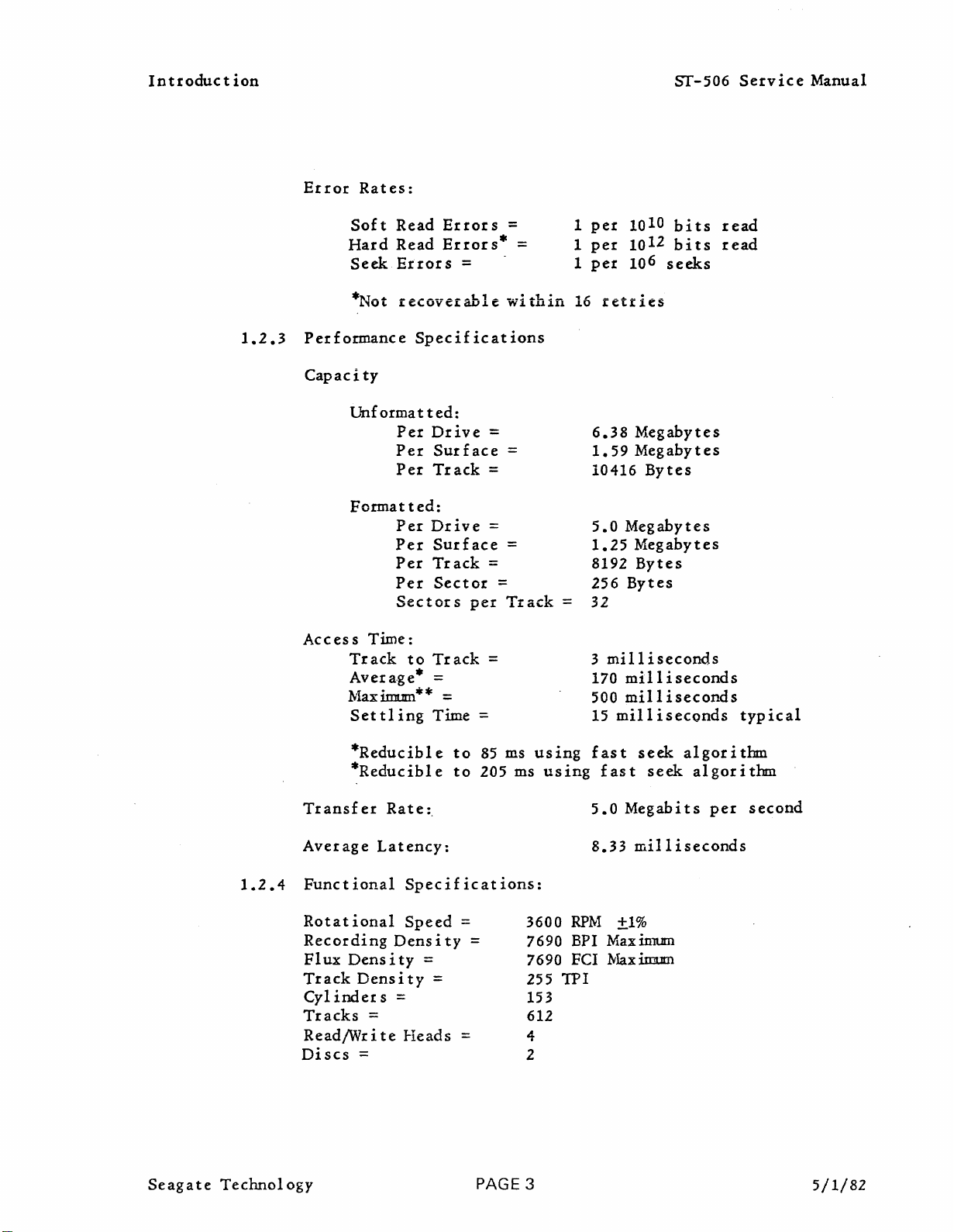
Figure-2.1
(MFM)
replacing
bits
Clock
written
write
by
rate.
through
early
disc
density
floppy
shipping.
(Track
as
This
double-density
clock
are
notpres
bits
in
data
the
The
Sf-506
152.
The
and
drive
format.
disc
Format).
the
encoding
bits
ent
are
written
the
middle.
may
require
controller
requires
The
recommended
late
written
isaslightly
drives.
Data
fields
with
in
at
to
data
This
All
The
Seagate
each
of
identification
field
m
It
not
format
Seagate
evaluation.
3%.
specified
containing
which
ark
should
required.
The
contains
and
is
format
ST-506
environmental
8192
error
be
an
The
soft-sector
256
bytes
bytes
field
that
cylinder,
checking
noted
Use
integral
that
of
uses
format
specification
format
of
are
is
different
head,
polynomials.
the
any
other
part
of
Cyclic
also
and
power
divides
data.
data."
format
the
Redundancy
allows
for
Total
than
and
format
drives'
foraplus
spindle
limits.
Each
any
sector
used
requires
performance
speed
each
track
by
track
capacity
sector
other
information
Seagate
careful
Checking
or minus
variation
into
is
identified
on
the
as
is
recommended
evaluation,
and
(eRC)
speed
32
sectors
is
10416
drive.
well
operation.
for
variation
is
1%
as
over
with
bytes,
by
The
address
and
as
the
The
error
the
an
ID
of
Seag
ate
Technology
PAGE 4
5/1/82
FIGURIE
20
-0
l>
C)
m
c.n
INDEX
~
WRITE
UPDATE
----fl
I
I
I
I
I
Gap 1
16X
SYNC
4E
13XOOA11
~
lOAM
FE
ID
Field
eSC
IrI
~I~I~I~
TRACK
~
Repeated32,times
--
- Gap
C
3xOO
FORMAl·
(314
2-
----
113xoo A11F81
J
'--r
Data
AM
AS
SHIPPED
Bytes)
Data
Fie~d
256
Data
I
GaIP
~I~
C C
3XOO
,
__
3
f15X4E
Gap4
352X
4E
Nominal
rL
__
lL--' _
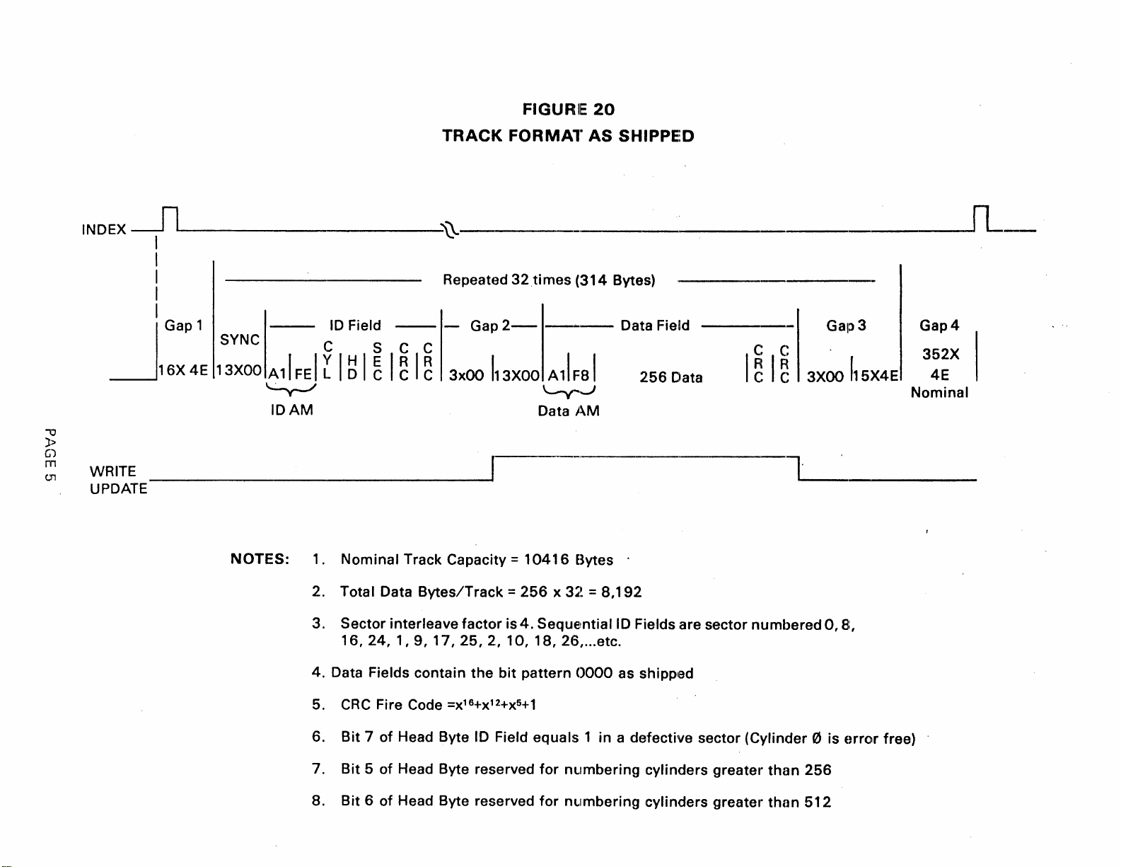
NOTES:
1. Nominal Track Capacity =
2. Total Data
3. Sector interleave factor is4.SequE!ntiallD Fieldsare sector numbered0,B,
16,24,
4. Data Fields contain
CRC
5.
6.
Bit7of
Bit5of
7.
8.
Bit6of
Bytes/Track=256
1,9,17,25,2,
the
Fire Code
Head Byte ID Field equals 1 in a defective sector (Cylinder 0 is
Head Byte reserved
Head Byte reserved
=X16+X12+X5+1
10,
bit
10416
x
18,
pattern
for
for
Bytes .
3~~
=
8,192
26,
...
etc.
0000
nl.lmberingcylinders
nl.lmbering cylinders greater
as shipped
greate,"
than
than
256
512
orror
free)
Theory
of
Operations
ST-506
Service
Manual
2.1.3
The
technology.
contact
radial
supported
The
grams.
operating
cylinder
height
micrcinches.
The
orientations
Winchester
head/£lexture
resistive
2.1.4
The
discs
oxide
by
40
diameter.
Winchester
Seagate
start-stop
track
on
Winchester
This
conditions.
is
of
load
force
to
Discs
ST-506
as
the
technology.
130mm
microinches
Technology
The
density
an
heads
is
19
microinches
the
heads
of
the
heads
assembly
head
disc
recording
outside
Heads
head/flexture
operation.
is
~1r
bearing
used
the
typical
Tne
at
of
9.5
grams
disc
drive
to
incorporates
and/or
drive
media.
The
diameter.
increasing
ST-506
(supporting
Bit
255
TPI.
creat~d
are
loaded
value
flying
withatolerance
the
any
media
uses
actual
linearly
height
outermost
is
sufficient
will
not
significant
an
damage
two
non-removable
The
discs
disc
Thickness
from
uses
The
by
conventional
arm)
packing
heads,
the
toward
to
allow
of
cylinder
enough
affect
extremely
when
are
dimensions
of
the
the
assembly
density
rotating
required
the
of
±3
the
degree.
shipping.
designed
magnetic
inside
Winchester
is
designed
is
7690 BPI and
when
the
heads
microincheseThe
so
low
are40mm
operational,
disc.
disc
at
is
24
that
flying
Additionally,
mass
double
upon
coating
diameter
surface
stability
the
microinches,
various
height
design
sided51/4
curr
inside
to
head
at
in
innermost
flying
mounting
of
that
ent
diameter
is
20
the
outside
for
the
are
9.5
all
±3
the
the
is
inch
iron
to
Seag
ate
Teclmology
The
disc
thickness.
The
disc
minimum
expectancy
2.1.5
All
filtration
the
functions.
seal
auxilIary
normal
the
Air
drives
life
ed
He
outside
surface
This
lubricant
of
10,000
of5years.
Filtration
manufactured
system.
of
the
First,
ad/D
isc
port
operation
allows
environm
is
value
start/stop
No
drive.
the
Assembly
there
coated
is
equivalent
has
sufficient
System
by
Sea&-ate
maintenance
The
filter
pressure
is
ent.
withaTeflon
to
abrasion
cycles.
Technology
or
adj.ustments
integral
maintains
throughout
equalization
no
measurable
PAGE 6
lubricant
a
uniform
The
0.3
Class
the
air
resistance
magnetic
incorporate
micron
100
IiIe
of
with
flow
40
to
60
monomolecular
to
discs
an
are
needed
air
filter
standards
the
drive.
ambient
between
angstroms
withstand
have
integral
throughout
performs
inside
Second,
air.
the
During
HDA
film.
a
life
air
two
the
an
and
5/1/82
in
a
Theory
of
2.2
Op
er
ations
Mechar..ical
ST-506
Service
Manual
2.2.1
The
Winchester
the
routine.
by
fJ/Phase
The
light-emitting-diode
heads
stepper
components
as
2.2.2
The
to
the
width.
The
transducer
preamplifier.
the
TracktJSensor
Track
internal
The
the
controller.
"A".
Track
are
positioned
motor
long
as
the
Index
Index
the
Index
Index
drive
sensor
interface
sensor
DC
~
optical
heads
drive
Track
tJ
shaft
of
light
Sensor
sensor
type.
The
returns
are
control
~
Note
optical
and
mechanically
the
sensor.
beam
provides
of
the
outputs
used
This
case
to
interrupter
positioned
electronics
signal
an
at
ST-506
is
that
interrupter
infrared
cylinder
The
remains
an
a
pulse
on
cylindrical
of
the
the
drive
aiso
the
index
drive.
the
over
signal
sensitive
J',
breaks
sensor
broken.
that
ST-506
sensor
casting.
provides
cylinder
during
output
at
an
the
will
pulse
Once
sensor
is
an
tJ.
the
power-on
to
the
drive
the
interfaceis
incorporates
photo-transistor.
interrupter
light
to
is
grounded
beam
outputavalid
the
recalibration
each
typically
revolution
drive
is
incorporates
output
This
arm
200
electrically
whenever
signalisused
auto-recalibrate
interface
an
attached
between
TrackfJsignal
microseconds
of
the
really
infrared
When
the
circuit
(16.67
reluctance
a
built-in
which
for
Track
to
the
by
use
the
the
two
and
ms),
in
ties
Seag
ate
Technology
The
hub
ferrous
the
spindle
the
Index
Note:
is
set
to
2.2.3
The
ST-506
hub
and
removing
hub.
of
the
composition
motor
sensor,
The
dimension
30 mils
Ground
incorporates
the
drive
all
Spring
unwanted
spindle
and
causes
therefore
(.030'~
casting.
motor
the
the
between
at
static
has
other
ferrous
inducing
the
the
factory.
a
grounding
This
electrical
PAGE 7
two
metal
is
non-magnetic.
tab
to
the
pulse
spindle
contact
ground
pass
output.
motor
spring
charges
tabs
attached;
within
tab
between
performs
from
Each
close
and
revolution
the
the
spindle
the
spindle
one
is
proximity
Index
the
sensor
motor
task
motor
5/1/82
of
a
of
of
of
Theory
of
Oper
ations
ST-506
Service
Manual
2.2.4
The
when
the
engages
The
designed
maximum
The
matches
the
(.0
SpindleBrake
ST-506
'DC
+12V
. ,
pad
brake
spindle
IOU). "
uses
power
supply.
against
contact
to
exceed
current
must
the
spindle
motor
an
electromechanical
is
removed.
the
material
When
spindle
The
+12V
motor
is
20,000 cy,cles. When
of
267 milliamps. '
be
adjusted
motor
hub
hub. When
and
the
brake
spindle
is
removed
hub
to
brake
slow
ofarubber-cork
energized,
so
that
the
disengaged,
pad
contact
to
is
from
the
composition
contour
the
should
slow
the
energized
the
drive,
motor.
the
brake
of
the
dimension
be
spindle
directly
with
will
pad
set
the
wear
draw
contact
between
at
10 mils
motor
from
brake
life
a
Seagate
Technology
PAGE 8
5/1/82
Theory
of
2.3
Operations
Electrical
Theory/Flowchart
ST-S06
Service
Manual
~L
SFNSCB
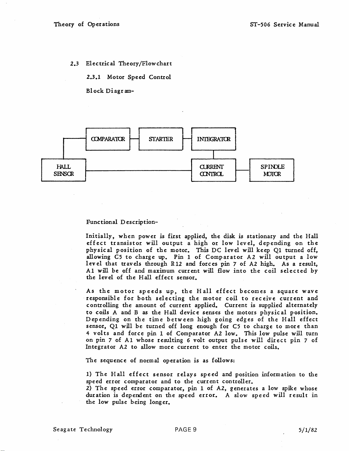
2.3.1
Block
Motor
Diagram-
Speed
Control
I I I
CI:MPARAKR
FunctionalDescription-
Initially,
effect
physical
allowing
level
Al
the
that
will
level
transistor
be
H
I
when
position
CS
to
travels
off
ot"
the
SfAR1ER
I I
power
will
of
charge
through
and
maximum
Hall
is
output
the
up.
effect
H
first
applied,
motor.
Pin
R12 and
current
sensor.
,
INIEGRA1rn
C1.RRENT
CINIRa..
i
I I
the
disk
a
1
high
of
or
This
DC
Comparator
forces
will flow
low
level
pin7of
1
~
I
is
stationary
level,
into
will
A2
A2
depending
keep
will
the
SPINJLE
~DKR
Ql
output
high.
coil
and
the
on
turned
As a
selected
Hall
the
off,
a
low
result,
by
Seag
ate
Technology
As
the
responsible
controlling
to
coils
A
Depending
sensor,
4
on
Integrator
The
1)
speed
2)
duration
the
Ql
volts
pin7of
sequence
The
Hall
error
The
speed
low
pulse
motor
for
the
andB
on
will
and
force
Al
A2
effect
comparator
is
dependent
speeds
both
amount
the
be
whose
to
allow
of
normal
error
being
selecting
of
as
the
time
turned
pin1of
resulting
more
operation
sensor
and
comparator,
on
longer.
up,
current
Hall
between
off
Comparator
current
relays
to
the
speed
PAGE
the
the
device
long
6
the
pin1of
Hall
motor
applied.
senses
high
enough
volt
output
to
is
as follows:
speed
current
error.
9
effect
coil
Current
the
going
for
A2
low.
enter
and
controller.
A2,
A
becomes
to
is
motors
edges
CS
to
This
pulse
the
generates
will
motor
position
slow
receive
supplied
physical
of
the
charge
low
direct
coils.
information
a low
speed
a
to
pulse
will
square
current
wave
alternately
position.
Hall
spike
mor
will
pin
result
effect
ethan
to
whose
5/1/82
and
turn
7
the
of
in
Theory
of
Oper
3)
The
to
maximum
speed
biases
4)
appropriate
the
5)
The
attaining
ations
pass
Pin
current
speed
a
error
error
the
integrator.
7
of
current
proper
error
low
frequency
during
information
Integrator
for
biasing
sourc
e. control,
speed
information
signal
start
and
A2
both
IC
A3,
as
directed
enters
directly
up.
The
combines
translates
halves
supplies
by IC
of
the
starting
starting
it
the
Ie AI:;
the
AI.
to
with
error
which
proper
ST-506
circuit
the
integrator
circuit
a
carrier
information
functions
amount
Servic
which
also
e Manual
functions
indic
inverts
that
properly
intoalevel
to
control
of
current
ating
the
for
Seagate
Technology
PAGE 10
5/1/82
Theory
of
Operations
ST-506
Servic
e Manual
I
~
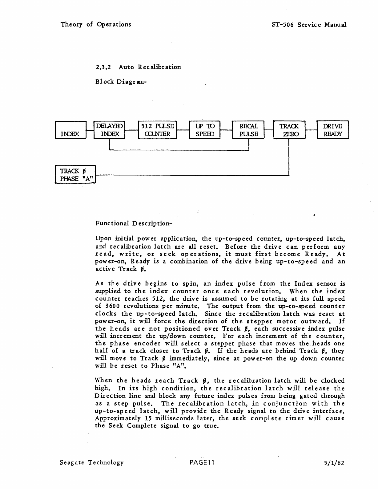
2.3.2
Block
AutoRecalibration
Diagram-
512PlLSE
aINIER
lP
10
SPEID
RECAL
PULSE
TRACK
ZERO
DRIVE
READY
~AIJ---------------------.;_......J
FunctionalDescription-
Upon
and
read,
power-on,
active
initial
recalibration
Track
power
write,
Ready
~.
application,
latch
or
isacombination
seek
are
all
operations,
the
reset.
of
up-to-speed
Before
it
must
the
drive
counter,
the
drive
first
being
up-to-speed
can
perform
become
up-to-speed
Ready.
latch,
and
any
At
an
As
the
drive
supplied
counter
of
3600
clocks
power-on,
the
will
the
half
will
will
When
high.
Direction
as
up-to-speed
Approximately
the
to
reaches
revolutions
the
heads
increment
phase
ofatrack
move
be
reset
the
In
its
line
a
step
Seek
Complete
it
are
encoder
to
heads
pulse.
begins
the
index
512,
up-to-speed
will
not
the
closer
Track~immediately,
to
Phase
high
and
latch,
15
to
spin,
counter
the
drive
per
minute.
latch.
force
the
positioned
up/down
will
to
select
Track~.
"A".
reach
block
milliseconds
Track
condition,
any
The
recalibration
will
provide
signal
to
direction
counter.
go
an
once
is
The
Since
over
a
~,
the
future
later,
true.
index
assumed
stepper
If
since
the
recalibration
index
the
the
pulse
each
output
the
of
the
Track
For
each
phase
the
at
recalibration
pulses
latch,
Ready
seek
from
revolution.
to
be
rotating
from
recalibration
stepper
~,
heads
power-on
the
each
increment
that
are
latch
from
in
conjunction
signal
complete
to
the
Index
When
at
up-to-speed
latch
motor
successive
of
moves
behind
the
latch
being
the
the
Track
up down
will
will
gated
drive
timer
sensor
the
its
full
counter
was
reset
outward.
index
the
counter,
heads
~,
counter
be
clocked
release
through
with
interface.
will
is
index
speed
at
If
pulse
one
they
the
the
cause
Seag
ate
Teclmology
PAGE11
5/1/82

Theory
of
Operations
The
normal
will
normal.
active
operations
stay
If
set
state
until
this
of
Seek
can
power
occurs,
Complete
begin.
is
interrupted
the
recalibration
The
is
a
signal
up-to-speed
or
drops
sequen.ce
ST-506
to
the
and
recalibration
·more
will
Service
controller
than
again
20%
be
initiated.
Manual
that
latches
below
Seag
ate
Technology
PAGE 12
5/1/82
Theory
of
Oper
ations
ST-506
Service
Manual
I
I
DRIVE
DRIVE
DRIVE
DRIVE
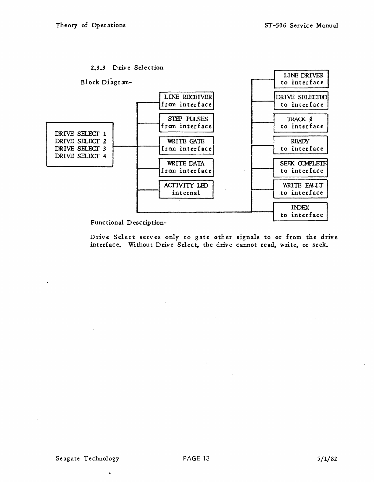
2.3.3
Block
SELECf 1
SELECT
SELECf 3
SELECf
Functlonal
Drive
interface.
Drive
Diagram-
2
4
I
Select
Selection
0 esc I1p
serves
Without
LINE
fran
I
fran
fran
fran
interface
SIEP
interface
WRITE
interface
WRITE
interface
REOHVER
Pi.LSES I
GA1E
DATA
A~IVIlY
[
tnternal
tlon-
only
Drive
to
Select,
~
gate
the
I
I
other
drive
r
signals
cannot
to
read,
LINE
to
interface
DRIVE
to
interface
UACK
I
to
interface
I
READY
to
interface
SEEK
to
interface
1
WR~1E
to
to
or
write,
interface
IIDEX
interface
from
I
DRIVER
SELECIID
_ I
<XMPlEIE
FAU.T I
the
drive
or
seek.
I
I
I
Seagate
Technology
PAGE 13
5/1/82
 Loading...