

Seagate ST373405LW, ST373405LWV, ST373405LC, ST373405LCV, ST336605LC Product Manual
...
. . . . . . . . . . . . . . . . . . . . . . . . . . . . . . . . . . . . . . . . . . . . . . . . .
Cheetah 73LP Family:
. . . . . . . . . . . . . . . . . . . . . . . . . . . . . . . . . . . . . . . . . . . . . . . . .
ST373405LW/LWV/LC/LCV
. . . . . . . . . . . . . . . . . . . . . . . . . . . . . . . . . . . . . . . . . . . . . . . . .
ST336605LC/LCV
. . . . . . . . . . . . . . . . . . . . . . . . . . . . . . . . . . . . . . . . . . . . . . . . .
. . . . . . . . . . . . . . . . . . . . . . . . . . . . . . . . . . . . . . . . . . . . . . . . .
Product Manual, Volume 1
. . . . . . . . . . . . . . . . . . . . . . . . . . . . . . . . . . . . . . . . . . . . . . . . .


. . . . . . . . . . . . . . . . . . . . . . . . . . . . . . . . . . . . . . . . . . . . . . . . .
Cheetah 73LP Family:
. . . . . . . . . . . . . . . . . . . . . . . . . . . . . . . . . . . . . . . . . . . . . . . . .
ST373405LW/LWV/LC/LCV
. . . . . . . . . . . . . . . . . . . . . . . . . . . . . . . . . . . . . . . . . . . . . . . . .
ST336605LC/LCV
. . . . . . . . . . . . . . . . . . . . . . . . . . . . . . . . . . . . . . . . . . . . . . . . .
. . . . . . . . . . . . . . . . . . . . . . . . . . . . . . . . . . . . . . . . . . . . . . . . .
Product Manual, Volume 1
. . . . . . . . . . . . . . . . . . . . . . . . . . . . . . . . . . . . . . . . . . . . . . . . .

© 2001 Seagate Technology LLC All rights reserved
Publication number: 100109943, Rev. C
May 2001
Seagate, Seagate Technology, and the Seagate logo are registered tradema rks of Seagate Technology LLC.
Cheetah, SeaFAX, SeaFONE, SeaBOARD, and SeaTDD are either re gistered trademarks or tradema rks of
Seagate Technology LLC. Other product names are registered trademarks or trademarks of their owners.
Seagate reserves the right to change, without notice, product offerings or specifications. No part of this publica-
tion may be reproduced in any form without written permission of Seagate Technology LLC.

Revision status summary sheet
Notice.
Product Manual 100109943 is Volume 1 of a two volume document with the SCSI Interface information
in the SCSI Interface Product Manual, part number 75789509.
If you need the SCSI Interface information, order the SCSI Interface Product Manual, part number
75789509.
Revision Date Writer/Engineer Sheets Affected
Rev. A (Class C Release) 11/6/2000 L. Newman/J. Nowitzke 1/1, v thru viii, 1-76.
Rev. B (Class A Release) 04/12/2001 L. Newman/J. Nowitzke All pages.
Rev. C 05/17/2001 L. Newman/J. Nowitzke Page 45.


Cheetah 73LP Product Manual, Rev. C v
Contents
1.0 Scope . . . . . . . . . . . . . . . . . . . . . . . . . . . . . . . . . . . . . . . . . . . . . . . . . . . . . . . . . . . . . . . . . . . . . . . . . . 1
2.0 Applicable standards and reference documentation. . . . . . . . . . . . . . . . . . . . . . . . . . . . . . . . . . . . 3
2.1 Standards. . . . . . . . . . . . . . . . . . . . . . . . . . . . . . . . . . . . . . . . . . . . . . . . . . . . . . . . . . . . . . . . . 3
2.1.1 Electromagnetic compatibility . . . . . . . . . . . . . . . . . . . . . . . . . . . . . . . . . . . . . . . . . . 3
2.1.2 Electromagnetic susceptibility. . . . . . . . . . . . . . . . . . . . . . . . . . . . . . . . . . . . . . . . . . 3
2.2 Electromagnetic compliance . . . . . . . . . . . . . . . . . . . . . . . . . . . . . . . . . . . . . . . . . . . . . . . . . . 3
2.3 Reference documents . . . . . . . . . . . . . . . . . . . . . . . . . . . . . . . . . . . . . . . . . . . . . . . . . . . . . . . 4
3.0 General description. . . . . . . . . . . . . . . . . . . . . . . . . . . . . . . . . . . . . . . . . . . . . . . . . . . . . . . . . . . . . . . 5
3.1 Standard features. . . . . . . . . . . . . . . . . . . . . . . . . . . . . . . . . . . . . . . . . . . . . . . . . . . . . . . . . . . 7
3.2 Media characteristics . . . . . . . . . . . . . . . . . . . . . . . . . . . . . . . . . . . . . . . . . . . . . . . . . . . . . . . . 7
3.3 Performance. . . . . . . . . . . . . . . . . . . . . . . . . . . . . . . . . . . . . . . . . . . . . . . . . . . . . . . . . . . . . . . 7
3.4 Reliability . . . . . . . . . . . . . . . . . . . . . . . . . . . . . . . . . . . . . . . . . . . . . . . . . . . . . . . . . . . . . . . . . 7
3.5 Unformatted and formatted capacities . . . . . . . . . . . . . . . . . . . . . . . . . . . . . . . . . . . . . . . . . . . 8
3.6 Programmable drive capacity. . . . . . . . . . . . . . . . . . . . . . . . . . . . . . . . . . . . . . . . . . . . . . . . . . 8
3.7 Factory installed accessories. . . . . . . . . . . . . . . . . . . . . . . . . . . . . . . . . . . . . . . . . . . . . . . . . . 8
3.8 Options (factory installed). . . . . . . . . . . . . . . . . . . . . . . . . . . . . . . . . . . . . . . . . . . . . . . . . . . . . 8
3.9 Accessories (user installed) . . . . . . . . . . . . . . . . . . . . . . . . . . . . . . . . . . . . . . . . . . . . . . . . . . . 8
4.0 Performance characteristics . . . . . . . . . . . . . . . . . . . . . . . . . . . . . . . . . . . . . . . . . . . . . . . . . . . . . . . 9
4.1 Internal drive characteristics (transparent to user). . . . . . . . . . . . . . . . . . . . . . . . . . . . . . . . . . 9
4.2 SCSI performance characteristics (visible to user) . . . . . . . . . . . . . . . . . . . . . . . . . . . . . . . . . 9
4.2.1 Access time . . . . . . . . . . . . . . . . . . . . . . . . . . . . . . . . . . . . . . . . . . . . . . . . . . . . . . . 9
4.2.2 Format command execution time (minutes) . . . . . . . . . . . . . . . . . . . . . . . . . . . . . . . 9
4.2.3 Generalized performance characteristics . . . . . . . . . . . . . . . . . . . . . . . . . . . . . . . . . 9
4.3 Start/stop time . . . . . . . . . . . . . . . . . . . . . . . . . . . . . . . . . . . . . . . . . . . . . . . . . . . . . . . . . . . . 10
4.4 Prefetch/multi-segmented cache control . . . . . . . . . . . . . . . . . . . . . . . . . . . . . . . . . . . . . . . . 10
4.5 Cache operation. . . . . . . . . . . . . . . . . . . . . . . . . . . . . . . . . . . . . . . . . . . . . . . . . . . . . . . . . . . 11
4.5.1 Caching write data . . . . . . . . . . . . . . . . . . . . . . . . . . . . . . . . . . . . . . . . . . . . . . . . . 11
4.5.2 Prefetch operation . . . . . . . . . . . . . . . . . . . . . . . . . . . . . . . . . . . . . . . . . . . . . . . . . 12
4.5.3 Optimizing cache performance for desktop and server applications . . . . . . . . . . . 12
5.0 Reliability specifications . . . . . . . . . . . . . . . . . . . . . . . . . . . . . . . . . . . . . . . . . . . . . . . . . . . . . . . . . 13
5.1 Error rates . . . . . . . . . . . . . . . . . . . . . . . . . . . . . . . . . . . . . . . . . . . . . . . . . . . . . . . . . . . . . . . 13
5.1.1 Environmental interference. . . . . . . . . . . . . . . . . . . . . . . . . . . . . . . . . . . . . . . . . . . 13
5.1.2 Read errors. . . . . . . . . . . . . . . . . . . . . . . . . . . . . . . . . . . . . . . . . . . . . . . . . . . . . . . 13
5.1.3 Write errors. . . . . . . . . . . . . . . . . . . . . . . . . . . . . . . . . . . . . . . . . . . . . . . . . . . . . . . 13
5.1.4 Seek errors . . . . . . . . . . . . . . . . . . . . . . . . . . . . . . . . . . . . . . . . . . . . . . . . . . . . . . . 13
5.2 Reliability and service. . . . . . . . . . . . . . . . . . . . . . . . . . . . . . . . . . . . . . . . . . . . . . . . . . . . . . . 14
5.2.1 Mean time between failure (MTBF) . . . . . . . . . . . . . . . . . . . . . . . . . . . . . . . . . . . . 14
5.2.2 Preventive maintenance . . . . . . . . . . . . . . . . . . . . . . . . . . . . . . . . . . . . . . . . . . . . . 14
5.2.3 Service life . . . . . . . . . . . . . . . . . . . . . . . . . . . . . . . . . . . . . . . . . . . . . . . . . . . . . . . 14
5.2.4 Service philosophy . . . . . . . . . . . . . . . . . . . . . . . . . . . . . . . . . . . . . . . . . . . . . . . . . 14
5.2.5 Service tools . . . . . . . . . . . . . . . . . . . . . . . . . . . . . . . . . . . . . . . . . . . . . . . . . . . . . . 14
5.2.6 Hot plugging Cheetah 73LP disc drives . . . . . . . . . . . . . . . . . . . . . . . . . . . . . . . . . 15
5.2.7 S.M.A.R.T. . . . . . . . . . . . . . . . . . . . . . . . . . . . . . . . . . . . . . . . . . . . . . . . . . . . . . . . 15
5.2.8 Drive Self Test (DST) . . . . . . . . . . . . . . . . . . . . . . . . . . . . . . . . . . . . . . . . . . . . . . . 16
5.2.9 Product warranty. . . . . . . . . . . . . . . . . . . . . . . . . . . . . . . . . . . . . . . . . . . . . . . . . . . 19
6.0 Physical/electrical specifications . . . . . . . . . . . . . . . . . . . . . . . . . . . . . . . . . . . . . . . . . . . . . . . . . . 21
6.1 AC power requirements . . . . . . . . . . . . . . . . . . . . . . . . . . . . . . . . . . . . . . . . . . . . . . . . . . . . . 21
6.2 DC power requirements . . . . . . . . . . . . . . . . . . . . . . . . . . . . . . . . . . . . . . . . . . . . . . . . . . . . . 21
6.2.1 Conducted noise immunity . . . . . . . . . . . . . . . . . . . . . . . . . . . . . . . . . . . . . . . . . . . 22
6.2.2 Power sequencing . . . . . . . . . . . . . . . . . . . . . . . . . . . . . . . . . . . . . . . . . . . . . . . . . 22
6.2.3 12 V - Current profile . . . . . . . . . . . . . . . . . . . . . . . . . . . . . . . . . . . . . . . . . . . . . . . 22
6.3 Power dissipation . . . . . . . . . . . . . . . . . . . . . . . . . . . . . . . . . . . . . . . . . . . . . . . . . . . . . . . . . . 25
6.4 Environmental limits . . . . . . . . . . . . . . . . . . . . . . . . . . . . . . . . . . . . . . . . . . . . . . . . . . . . . . . . 27

vi Cheetah 73LP Product Manual, Rev. C
6.4.1 Temperature . . . . . . . . . . . . . . . . . . . . . . . . . . . . . . . . . . . . . . . . . . . . . . . . . . . . . .27
6.4.2 Relative humidity . . . . . . . . . . . . . . . . . . . . . . . . . . . . . . . . . . . . . . . . . . . . . . . . . . .27
6.4.3 Effective altitude (sea level). . . . . . . . . . . . . . . . . . . . . . . . . . . . . . . . . . . . . . . . . . .28
6.4.4 Shock and vibration . . . . . . . . . . . . . . . . . . . . . . . . . . . . . . . . . . . . . . . . . . . . . . . . .28
6.4.5 Air cleanliness . . . . . . . . . . . . . . . . . . . . . . . . . . . . . . . . . . . . . . . . . . . . . . . . . . . . .30
6.4.6 Acoustics . . . . . . . . . . . . . . . . . . . . . . . . . . . . . . . . . . . . . . . . . . . . . . . . . . . . . . . . .30
6.4.7 Electromagnetic susceptibility . . . . . . . . . . . . . . . . . . . . . . . . . . . . . . . . . . . . . . . . .30
6.5 Mechanical specifications . . . . . . . . . . . . . . . . . . . . . . . . . . . . . . . . . . . . . . . . . . . . . . . . . . . .3 1
7.0 Defect and error management . . . . . . . . . . . . . . . . . . . . . . . . . . . . . . . . . . . . . . . . . . . . . . . . . . . . .33
7.1 Drive internal defects. . . . . . . . . . . . . . . . . . . . . . . . . . . . . . . . . . . . . . . . . . . . . . . . . . . . . . . .33
7.2 Drive error recovery procedures . . . . . . . . . . . . . . . . . . . . . . . . . . . . . . . . . . . . . . . . . . . . . . .33
7.3 SCSI systems errors . . . . . . . . . . . . . . . . . . . . . . . . . . . . . . . . . . . . . . . . . . . . . . . . . . . . . . . .34
8.0 Installation . . . . . . . . . . . . . . . . . . . . . . . . . . . . . . . . . . . . . . . . . . . . . . . . . . . . . . . . . . . . . . . . . . . . .35
8.1 Drive ID/option select header . . . . . . . . . . . . . . . . . . . . . . . . . . . . . . . . . . . . . . . . . . . . . . . . .35
8.1.1 Notes for Figures 15, 16, and 17. . . . . . . . . . . . . . . . . . . . . . . . . . . . . . . . . . . . . . .38
8.1.2 Function description. . . . . . . . . . . . . . . . . . . . . . . . . . . . . . . . . . . . . . . . . . . . . . . . .39
8.2 Drive orientation . . . . . . . . . . . . . . . . . . . . . . . . . . . . . . . . . . . . . . . . . . . . . . . . . . . . . . . . . . .40
8.3 Cooling . . . . . . . . . . . . . . . . . . . . . . . . . . . . . . . . . . . . . . . . . . . . . . . . . . . . . . . . . . . . . . . . . .40
8.4 Drive mounting . . . . . . . . . . . . . . . . . . . . . . . . . . . . . . . . . . . . . . . . . . . . . . . . . . . . . . . . . . . .41
8.5 Grounding . . . . . . . . . . . . . . . . . . . . . . . . . . . . . . . . . . . . . . . . . . . . . . . . . . . . . . . . . . . . . . . .41
9.0 Interface requirements. . . . . . . . . . . . . . . . . . . . . . . . . . . . . . . . . . . . . . . . . . . . . . . . . . . . . . . . . . . .43
9.1 General description . . . . . . . . . . . . . . . . . . . . . . . . . . . . . . . . . . . . . . . . . . . . . . . . . . . . . . . . .43
9.2 SCSI interface messages supported. . . . . . . . . . . . . . . . . . . . . . . . . . . . . . . . . . . . . . . . . . . .43
9.3 SCSI interface commands supported . . . . . . . . . . . . . . . . . . . . . . . . . . . . . . . . . . . . . . . . . . .44
9.3.1 Inquiry Vital Product data. . . . . . . . . . . . . . . . . . . . . . . . . . . . . . . . . . . . . . . . . . . . .47
9.3.2 Mode Sense data. . . . . . . . . . . . . . . . . . . . . . . . . . . . . . . . . . . . . . . . . . . . . . . . . . .48
9.4 SCSI bus conditions and miscellaneous features supported . . . . . . . . . . . . . . . . . . . . . . . . .51
9.5 Synchronous data transfer . . . . . . . . . . . . . . . . . . . . . . . . . . . . . . . . . . . . . . . . . . . . . . . . . . .52
9.5.1 Synchronous data transfer periods supported. . . . . . . . . . . . . . . . . . . . . . . . . . . . .52
9.5.2 REQ/ACK offset. . . . . . . . . . . . . . . . . . . . . . . . . . . . . . . . . . . . . . . . . . . . . . . . . . . .52
9.6 Physical interface . . . . . . . . . . . . . . . . . . . . . . . . . . . . . . . . . . . . . . . . . . . . . . . . . . . . . . . . . .52
9.6.1 DC cable and connector . . . . . . . . . . . . . . . . . . . . . . . . . . . . . . . . . . . . . . . . . . . . .52
9.6.2 SCSI interface physical description . . . . . . . . . . . . . . . . . . . . . . . . . . . . . . . . . . . . .54
9.6.3 SCSI interface cable requirements . . . . . . . . . . . . . . . . . . . . . . . . . . . . . . . . . . . . .54
9.6.4 Mating connectors . . . . . . . . . . . . . . . . . . . . . . . . . . . . . . . . . . . . . . . . . . . . . . . . . .55
9.7 Electrical description . . . . . . . . . . . . . . . . . . . . . . . . . . . . . . . . . . . . . . . . . . . . . . . . . . . . . . . .63
9.7.1 Multimode—SE and LVD alternatives . . . . . . . . . . . . . . . . . . . . . . . . . . . . . . . . . . .63
9.8 Terminator requirements . . . . . . . . . . . . . . . . . . . . . . . . . . . . . . . . . . . . . . . . . . . . . . . . . . . . .65
9.9 Terminator power . . . . . . . . . . . . . . . . . . . . . . . . . . . . . . . . . . . . . . . . . . . . . . . . . . . . . . . . . .65
9.10 Disc drive SCSI timing. . . . . . . . . . . . . . . . . . . . . . . . . . . . . . . . . . . . . . . . . . . . . . . . . . . . . . .66
9.11 Drive activity LED . . . . . . . . . . . . . . . . . . . . . . . . . . . . . . . . . . . . . . . . . . . . . . . . . . . . . . . . . .67
10.0 Seagate Technology support services. . . . . . . . . . . . . . . . . . . . . . . . . . . . . . . . . . . . . . . . . . . . . . .69

Cheetah 73LP Product Manual, Rev. C vii
List of Figures
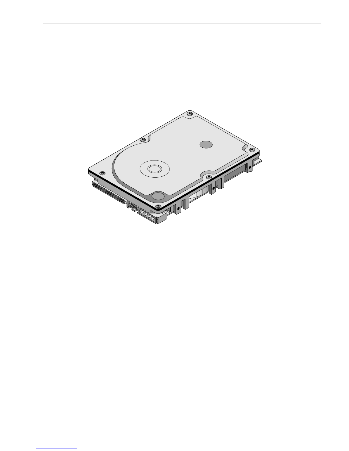
Figure 1. Cheetah 73LP family drive (ST373405LW shown) . . . . . . . . . . . . . . . . . . . . . . . . . . . . . . . . . 1
Figure 2. Cheetah 73LP family drive. . . . . . . . . . . . . . . . . . . . . . . . . . . . . . . . . . . . . . . . . . . . . . . . . . . . 6
Figure 3. Typical ST373405 drive +12 V current profile . . . . . . . . . . . . . . . . . . . . . . . . . . . . . . . . . . . . 22
Figure 4. Typical ST336605 drive +12 V current profile . . . . . . . . . . . . . . . . . . . . . . . . . . . . . . . . . . . . 23
Figure 5. Typical ST373405 drive +5 V current profile . . . . . . . . . . . . . . . . . . . . . . . . . . . . . . . . . . . . . 23
Figure 6. Typical ST336605 drive +5 V current profile . . . . . . . . . . . . . . . . . . . . . . . . . . . . . . . . . . . . . 24
Figure 7. ST373405 DC current and power vs. input/output operations per second (SE) . . . . . . . . . . 25
Figure 8. ST373405 DC current and power vs. input/output operations per second (LVD) . . . . . . . . . 25
Figure 9. ST336605 DC current and power vs. input/output operations per second (SE) . . . . . . . . . . 26
Figure 10. ST336605 DC current and power vs. input/output operations per second (LVD) . . . . . . . . . 26
Figure 11. Location of the HDA Temperature check point . . . . . . . . . . . . . . . . . . . . . . . . . . . . . . . . . . . 27
Figure 12. Recommended mounting . . . . . . . . . . . . . . . . . . . . . . . . . . . . . . . . . . . . . . . . . . . . . . . . . . . . 29
Figure 13. ST373405LW mounting configuration dimensions. . . . . . . . . . . . . . . . . . . . . . . . . . . . . . . . . 31
Figure 14. ST373405LC mounting configuration dimensions . . . . . . . . . . . . . . . . . . . . . . . . . . . . . . . . . 32
Figure 15. J6 jumper header . . . . . . . . . . . . . . . . . . . . . . . . . . . . . . . . . . . . . . . . . . . . . . . . . . . . . . . . . . 36
Figure 16. J5 jumper header (on LW models only) . . . . . . . . . . . . . . . . . . . . . . . . . . . . . . . . . . . . . . . . . 37
Figure 17. J2 option select header . . . . . . . . . . . . . . . . . . . . . . . . . . . . . . . . . . . . . . . . . . . . . . . . . . . . . 38
Figure 18. Air flow (suggested) . . . . . . . . . . . . . . . . . . . . . . . . . . . . . . . . . . . . . . . . . . . . . . . . . . . . . . . . 40
Figure 19. LW model drive physical interface (68-pin J1 SCSI I/O connector) . . . . . . . . . . . . . . . . . . . . 53
Figure 20. LC model drive physical interface (80-pin J1 SCSI I/O connector) . . . . . . . . . . . . . . . . . . . . 53
Figure 21. SCSI daisy chain interface cabling for LW drives. . . . . . . . . . . . . . . . . . . . . . . . . . . . . . . . . . 56
Figure 22. Nonshielded 68 pin SCSI device connector used on LW drives . . . . . . . . . . . . . . . . . . . . . . 57
Figure 23. Nonshielded 80 pin SCSI “SCA-2” connector, used on LC drives . . . . . . . . . . . . . . . . . . . . . 58
Figure 24. LVD output signals . . . . . . . . . . . . . . . . . . . . . . . . . . . . . . . . . . . . . . . . . . . . . . . . . . . . . . . . . 64
Figure 25. Typical SE-LVD alternative transmitter receiver circuits . . . . . . . . . . . . . . . . . . . . . . . . . . . . 64

Cheetah 73LP Product Manual, Rev. C 1
1.0 Scope
This manual describes Seagate Technology® LLC, Cheetah 73LP™ disc drives.
Cheetah 73LP dri ves suppor t the small computer system inte rface (SCSI) as descr ibed in the ANSI SPI-3
(SCSI Parallel Interface-3) interface specification to the extent described in this ma nual. The SCSI Interface
Product Manual (par t number 75789509) describ es general SCSI interface characteristics of t his and other
families of Seagate drives.
From this point on in this product manual the reference to Cheetah 73L P models is referred to as “the drive”
unless references to individual models are necessary.
Figure 1. Cheetah 73LP family drive (ST373405LW shown)

2 Cheetah 73LP Product Manual, Rev. C

Cheetah 73LP Product Manual, Rev. C 3
2.0 Applicable standards and reference documentation
The drive has been developed as a system peripheral to the highest standards of design and construction. The
drive depends upon i ts host equip ment to provide adequ ate power and environment i n order to achieve optimum performance and compli ance with applicable industry and governm ental regulations. Special attention
must be given in the areas of safety, power distribution, shielding, audible noise control, and temperature regulation. In particular, the drive must be secure ly mo unte d i n o rd er to guara ntee the s pec if ied per for ma nc e char acteristics. Mounting by bottom holes must meet the requirements of Section 8.4.
2.1 Standards
The Cheetah 73LP family complies with Seagate standards as noted in the appropriate sections of this Manual
and the Seagate SCSI Interface Product Manual, part number 75789509.
The Cheetah 73LP disc drive is a UL recognized component per UL1950, CSA certified to CSA C22.2 No. 950M89, and VDE certified to VDE 0805 and EN60950.
2.1.1 Electromagnetic compatibility
The drive, as delivered, is designed for system integration and installation into a suitable enclosure prior to use.
As such the drive is suppli ed as a subassembly and is not su bject to Subpar t B of Part 15 of the FCC Rules
and Regulations nor the Radio Interference Regulations of the Canadian Department of Communications.
The design characteristics of the drive serve to minimize radiation when installed in an enclosure that provides
reasonable shielding. As such, the drive is capable of meeting the Class B limits of the FCC Rules and Regulations of the Canadian Department of Communications when properly packaged. However, it is the user’s
responsibility to assure that the drive meets the appropriate EMI req uirements in their syst em. Shielded I/O
cables may be required if the e nclosure does not provide ad equate sh ielding. If the I/O c ables are externa l to
the enclosure, shielded cables should be used, with the shields grounded to the enclosure and to the host controller.
2.1.2 Electromagnetic susceptibility
As a component assembly, the drive is not required to meet any susceptibility per formance requ irements. It is
the responsibility of tho se integrating the dr ive within their sy stem s to perform thos e tests req uired and design
their system to ensu re that equipment operating in the sam e system as the drive or external to the s ystem
does not adversely affect the performance of the drive. See Section 5.1.1 and Table 2, DC power requirements.
2.2 Electromagnetic compliance
Seagate uses an independ ent laboratory to co nfirm compliance to the directives/standard(s) for CE Mark ing
and C-Tick Marking. The drive was tested in a representative system for typical applications. The selected system represents the most popular characteristics for test platforms. The system configurations include:
• Typical current use microprocessors
• 3.5-inch floppy disc drive
• Keyboard
• Monitor/display
•Printer
• External modem
•Mouse
Although the test system wi th this Seag ate mode l co mpl ie s to the dire cti ves/standa rd(s ), we cann ot gua rante e
that all systems will comply. The computer manufacturer or system i ntegrator shall confir m EMC complian ce
and provide CE Marking and C-Tick Marking for their product.
Electromagnetic compliance for the European Union
If this model has the CE Marki ng it complies with the European Union requirem ents of the Electromagnetic
Compatibility Direc tive 89/336/EEC o f 03 May 1989 as ame nded by Direct ive 92/31/EE C of 28 Ap r il 1992 an d
Directive 93/68/EEC of 22 July 1993.

4 Cheetah 73LP Product Manual, Rev. C
Australian C-Tick
If this model has the C-Tick Markin g it complies with the Australia/New Zea land Standard A S/NZS3548 199 5
and meets the Electro magnetic Compatibility (EMC) Framework requirements of Australia’s Spectrum Management Agency (SMA).
Korean MIC
If this model has the Korean Ministry of Information and Communication (MIC) logo, it complies with paragraph
1 of Articl e 11 of the Ele ctromagneti c Compatib ility (EM C) Control Regu lation and meets th e Electroma gnetic
Compatibility Framework requirements of the Radi o Research Laboratory (RRL) Minis try of Information and
Communication Republic of Korea.
Taiwanese BSMI
If this model has two Chinese words meani ng “EMC cer ti fication ” followed by an eight digit identification number, as a Marking, it complies with Chinese Na tional Standard (CNS) 13438 and meets the Electromagnetic
Compatibility (EMC) Framework requirements of the Taiwanese Bureau of Standa rds, Metrology, and Inspection (BSMI).
2.3 Reference documents
Cheetah 73LP Installation Guide Seagate P/N 100109946
SCSI Interface Product Manual Seagate P/N 75789509
ANSI small computer system interface (SCSI) document numbers:
T10/1143D Enhanced SCSI Parallel Interface (EPI)
T10/1236D SCSI Primary Commands-2 (SPC-2)
T10/996D SCSI Block Commands (SBC)
T10/1157D SCSI Architectural Mode l-2 (S AM - 2)
T10/1302D SCSI Parallel Interface Version 3 (SPI-3)
SFF-8451, Specification for SCA-2 Unshielded Connections
Package Test Specification Seagate P/N 30190-001 (under 100 lb.)
Package Test Specification Seagate P/N 30191-001 (over 100 lb.)
Specification, Acoustic Test Requirements, and Procedures Seagate P/N 30553-001
In case of conflict between this document and any referenced document, this document takes precedence.
Cheetah 73LP Product Manual, Rev. C 5
3.0 General description
Cheetah 73LP drives combine giant magnetoresistive (GMR) heads, partial response/maximum likelihood
(PRML) read channel el ectroni cs, embedd ed ser vo tech nology, and a wide Ultra160 SCSI interface to provide
high performance, high capaci ty data storage for a variety of syste ms inc luding en ginee ring work statio ns, network servers, mainframes, and supercomputers.
The Ultra160 interface uses negotiat ed transfer rates. These transfer rates will occur only if your host adapter
suppor ts these data transfer rates and is com patible with the requ ired hardware requir ements of the I/O circuit type. This dr ive also operates at SCSI-1 an d SCSI-2 data transfer rates for backward compati bility with
non-Ultra/Ultra2/Ultra3 SCSI host adapters.
Table 1 lists the features that differentiate the Cheetah 73LP models.
Table 1: Drive model number vs. differentiating features
[1] See Section 9.6 for details and definitions.
The drive records and recovers data on approximately 3.3-inch (84 mm) non-removable discs.
The drive suppor ts the Small Computer System Interface (SCSI) as descr ibed in the ANSI SCSI-2/SCSI-3
interface specifications t o the extent described in this manual (volume 1), which defines the product performance characteristics of the Cheetah 73LP family of drives, and the SCSI Interface Product Manual, part number 75789509, which describes the general interface characteristics of this and other families of Seagate SCSI
drives.
The drive’s interface supports multiple initiators, disconnect/reconnect, self-configuring host software, and
automatic features that relieve the host from the necessity of knowing the physical characteristics of the targets
(logical block addressing is used).
The head and disc assembly (HDA) is sealed at the factory. Air circulates within the HDA through a nonreplaceable filter to maintain a contamination-free HDA environment.
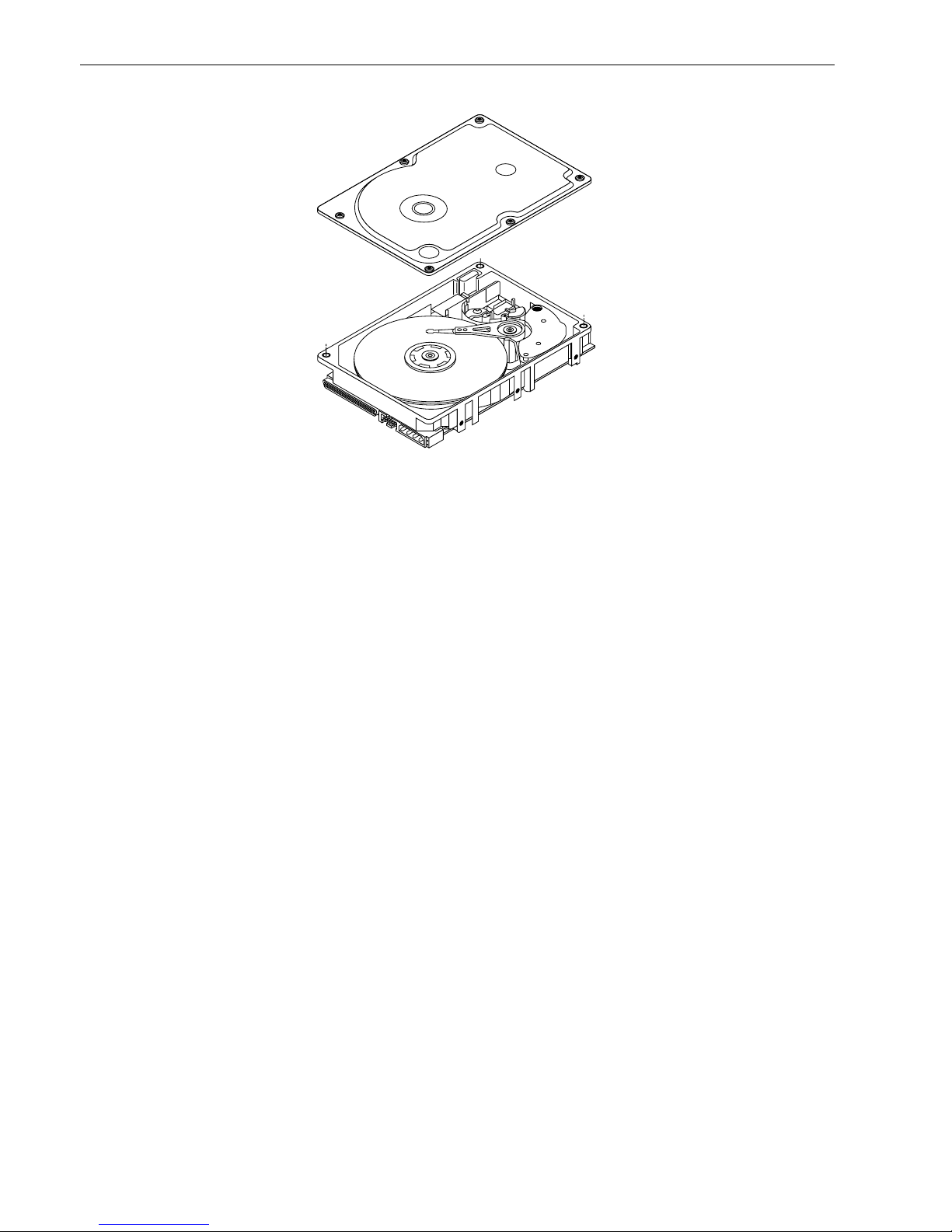
Refer to Figure 2 for an exploded view of the drive. This exploded view is for information only—never disassemble the HDA and do not attempt to service items in the se aled e nclosur e (head s, media, actuat or, etc.) as this
requires special facilities. The drive contains no replaceable parts. Opening the HDA voids your warranty.
Cheetah 73LP drives use a dedicated landing zone at the innermost radius of the media to eliminate the possibility of destroying or degrading da ta by landing in the d ata zone. The drive automa tically goes to the landing
zone when power is removed.
An automatic shipping lock prevents potential damage to the heads and discs that results from movement during shipping and ha ndl ing . T he shi ppi ng lock au toma tic al ly di se nga ges whe n power is applied to the drive and
the head load process begins.
Cheetah 73LP drives decode track 0 location data from the servo data embedded on each surface to eliminate
mechanical transducer adjustments and related reliability concerns.
A high-performance actuator assembly with a low-inertia, balanced, patented, straight-arm design provides
excellent performance with minimal power dissipation.
Model number
Number
of active
heads I/O circuit type [1]
Number of I/O
connector pins
Number of I/O
data bus bits
ST373405LW/LWV 8 Single-ended (SE) and low voltage
differential (LVD)
68 16
ST373405LC/LCV 8 Single-ended (SE) and low voltage
differential (LVD)
80 16
ST336605LC/LCV 4 Single-ended (SE) and low voltage
differential (LVD)
80 16
6 Cheetah 73LP Product Manual, Rev. C
Figure 2. Cheetah 73LP family drive

Cheetah 73LP Product Manual, Rev. C 7
3.1 Standard features
The Cheetah 73LP family has the following standard features:
• Integrated Ultra/Ultra2/Ultra3 SCSI controller
• Multimode SCSI drivers and receivers—single-ended (SE) and low voltage differential (LVD)
• 16 bit I/O data bus
• Asynchronous and synchronous data transfer protocol
• Firmware downloadable via SCSI interface
• Selectable even byte sector sizes from 512 to 4,096 bytes/sector
• Programmable sector reallocation scheme
• Flawed sector reallocation at format time
• Programmable auto write and read reallocation
• Reallocation of defects on command (post format)
• Enhanced ECC correction capability up to 240 bits
• Sealed head and disc assembly
• No preventative maintenance or adjustment required
• Dedicated head landing zone
• Embedded servo design
• Self diagnostics performed when power is applied to the drive
• 1:1 Interleave
• Zoned bit recording (ZBR)
• Vertical, horizontal, or top down mounting
• Dynamic spindle brake
• 4,096 kbyte data buffer (16,384 kbytes on LCV and LWV models)
• Hot plug compatibility (Section 9.6.4.2 lists proper host connector needed) for LC model drives
• Drive Self Test (DST)
3.2 Media characteristics
The media used on the dr ive has a di ameter of a pproximately 3 .3 in ches (8 4 mm). The alumi num substrat e is
coated with a thin film magneti c mat eria l, overcoated with a propr iet ar y prote ctive layer for improved durability
and environmental protection.
3.3 Performance
• Supports industry standard Ultra3 SCSI interface
• Programmable multi-segmentable cache buffer (see Section 4.5)
• 10,000 RPM spindle. Average latency = 2.99 ms
• Command queuing of up to 64 commands
• Background processing of queue
• Supports start and stop commands (spindle stops spinning)
3.4 Reliability
• 1,200,000 hour MTBF
• LSI circuitry
• Balanced low mass rotary voice coil actuator
• Incorporates industry-standard Self-Monitoring, Analysis and Reporting Technology (S.M.A.R.T.)
• 5-year warranty

8 Cheetah 73LP Product Manual, Rev. C
3.5 Unformatted and formatted capacities
Formatted capacity depends on the number of spare reallocation sectors reserved and the number of bytes per
sector. The following table shows the standard OEM model capacities:
Notes.
[1] Sector size selectable at for mat time. Users having the necessar y eq uipment may modify the data block
size before issuing a format co mmand and obtain different formatted capa cities than those listed. See
Mode Select Command and Format Command in the SCSI Interface Product Manual, part number
75789509.
[2] User available capacity depends on spare reallo cation scheme selec ted, the number of data tracks per
sparing zone, and the number of alternate sectors (LBAs) per sparing zone.
3.6 Programmable drive capacity
Using the Mode Select command, the drive can change its capacity to something less than maximum. See the
Mode Select Parameter List table in the SCS I Interface Product Manual, par t number 7578 9509. Refer to the
Parameter list block descriptor number of blocks field. A value of zero in the number of blocks field indi cates
that the drive shall not change the capacity it is curr ently formatte d to have. A number in the number of blocks
field that is less than the ma ximum number of L BAs changes the total drive capacity to the value in the block
descriptor number of blocks field. A value greater th an the max imum number of LB As is round ed down to th e
maximum capacity.
3.7 Factory installed accessories
OEM Standard dr ives are sh ip ped with the Ch eeta h 73L P Installation Guide, part number 100109946 (u nle ss
otherwise specified ). The factory also ships with the drive a small bag of jumper plugs us ed for the J2, J5, an d
J6 option select jumper headers.
3.8 Options (factory instal led)
All customer request ed options are incorporate d during production or packaged at the manufacturi ng facility
before shipping. Some of the options available are (not an exhaustive list of possible options):
• Other capacities can be ordered depending on sparing scheme and sector size requested.
• Single unit shipping pack. The drive is norm ally shipped in bulk packagin g to provide maximum protectio n
against transit damage. Units shipped individually require additional protection as provided by the single unit
shipping pack. Users planning single unit distribution should specify this option.
• The Cheetah 73LP Installation Guide, part number 100109946, is usually included with each standard OEM
drive shipped, but extra copies may be ordered.
3.9 Accessories (user installed)
The following accessories are available. All accessories may be installed in the field.
• Single unit shipping pack.
Formatted
data block size
512 bytes/sector [1] Unformatted
ST373405 088BB995h (73.4 GB) [2] 97.0 GB
ST336605 0445DCCBh (36.7 GB) [2] 48.5 GB

Cheetah 73LP Product Manual, Rev. C 9
4.0 Performance characteristics
4.1 Internal drive characteristics (transparent to user)
4.2 SCSI performance characteristics (visible to user)
The values given in Section 4.2.1 app ly to all mode ls of the Ch eetah 73LP family unless o therwise spec ified.
Refer to Section 9.10 and to the SC SI Interface Product Manual, part number 75789509, for additional timing
details.
4.2.1 Access time [5]
4.2.2 Format command execution time (minutes) [1]
4.2.3 Generalized performance characteristics
Data buffer transfer rate to/from disc media (one 512-byte sector):
ST373405 ST336605
Drive capacity 73.4 36.7 GByte (formatted, rounded off values)
Read/write heads 8 4
Bytes/track 397,385 397,385 Bytes (average, rounded off values)
Bytes/surface 12,100 12,100 Mbytes (unformatted, rounded off values)
Tracks/surface (total) 29,549 29,549 Tracks (user accessible)
Tracks/inch 38,000 38,000 TPI
Peak bits/inch 474 474 KBPI
Internal data rate 399-671 399-671 Mbits/sec (variable with zone)
Disc rotational speed 10,041 10,041 r/min (+
0.5%)
Average rotational latency 2.99 2.99 msec
Including controller overhead
(without disconnect) [1] [3]
Not including controller o v erhea d
(without disconnect) [1] [3]
Drive level Drive level
Read Write Read Write
msec msec
ST373405
Average—Typical [2] 5.3 5.7 5.1 5.5
Single Track—Typical [2] 0.6 0.8 0.4 0.6
Full Stroke—Typical [2] 9.6 10.0 9.4 9.8
ST336605
Average—Typical [2] 4.9 5.4 4.7 5.2
Single Track—Typical [2] 0.6 0.8 0.4 0.6
Full Stroke—Typical [2] 8.8 9.3 8.6 9.1
ST373405 ST336605
Maximum (with verify) 120 90
Maximum (no verify) 60 45
Minimum sector interleave 1 to 1
Minimum [3]* 38.4 MByte/sec
Average [3] 52.0 MByte/sec
Maximum [3] 63.9 MByte/sec

10 Cheetah 73LP Product Manual, Rev. C
SCSI interface data transfer rate (asynchronous):
Maximum instantaneous one byte wide 5.0 Mbytes/sec [4]
Maximum instantaneous two bytes wide 10.0 Mbytes/sec [4]
Synchronous formatted transfer rate Ultra2 SCSI Ultra3 SCSI
On narrow (8-bit) bus in LVD mode 5.0 to 40 Mbytes/sec 5.0 to 80 Mbytes/sec
On wide (16-bit) bus in LVD mode 5.0 to 80 Mbytes/sec 5.0 to 160 Mbytes/sec
Sector Sizes:
Default 512 byte user data blocks
Variable 512 to 4,096 bytes per sector in even number of bytes per sector.
If n (number of bytes per sector) is odd, then n-1 will be used.
Notes for Section 4.2.
[1] Execution time measured from receipt of the last byte of the Command Descr iptor Block (CDB) to the
request for a Status Byte Tr ansfer to the Initiator (excluding connect/disconnect).
[2] Typical access times are meas ured und er nomina l condition s of temperat ure, voltage, and hor izontal or i-
entation as measured on a representative sample of drives.
[3] Assumes no errors and no sector has been relocated.
[4] Assumes system ability to support the rates listed and no cable loss.
[5] Access time = controller overhead + average seek time.
Access to data = controller overhead + average seek time + latency time.
4.3 Start/stop time
After DC power at no minal voltage h as been appl ied, the d r ive becom es rea dy withi n 20 sec onds if the Mo tor
Start Opti on is disabled (i.e. the motor star ts as soon as the power has bee n applied). If a recoverable error
condition is detected during the start sequence, the drive executes a recovery procedure which may cause the
time to become rea dy to exceed 20 seconds. Dur ing spin up to ready time the dr ive responds to s ome commands over the SCSI interface in less than 3 seconds after application of power. Stop time is less than 30 seconds from removal of DC power.
If the Motor Star t Option is en abled, the inter nal cont roller accep ts the comm ands list ed in the SCSI In terface
Product Manual less th an 3 seconds after DC power has been applied. After the Motor Sta rt Comma nd has
been received the d rive becomes ready for nor mal opera tions withi n 20 seco nds typical ly (excluding an error
recovery procedure). The Mo tor Start Comm and can also be used to comm and the drive to stop the spindle
(see SCSI Interface Product Manual, part number 75789509).
There is no power control switch on the drive.
4.4 Prefetch/multi-segmented cache control
The drive provides prefetch (read look-ahead) and multi-segmented cache control algorithms that in many
cases can enhance system performance. “Cache” as used herein refers to the drive buffer storage space when
it is used in cache operations. To select prefetch and cache features the host sends the Mode Select command
with the proper values in th e applicable bytes in Mode Page 08h (see the SCSI Inte rface Product Manual).
Prefetch and cache operation are ind ependen t features from the stan dpoint th at each is enabled and disabled
independently via the Mode Select command. However , in actual operation the prefetch feature overlaps cache
operation somewhat as is noted in Section 4.5.1 and 4.5.2.
All default cache and prefetch Mode pa rameter values (Mode Page 08h) for standard OEM versions of this
drive family are given in Tables 7.
Read/write consecutive sectors on a track Yes
Flaw reallocation performance impact (for flaws reallocated at format time using
the spare sectors per sparing zone reallocation scheme.)
Negligible
Average rotational latency 2.99 msec

Cheetah 73LP Product Manual, Rev. C 11
4.5 Cache operation
In general, 3,600 kbytes (14,399 k bytes of the 16,3 84 kbytes in LWV and LCV models) of the 4,0 96 kbytes of
physical buffer space in the drive can be used as storage space for cache operations. The buffer can be divided
into logical segm ents (Mode Sele ct Page 08h, byte 13) from whic h data is read and to which da ta is written .
The drive maintains a table of logica l block disk medium ad dresse s of the data s tored in each segmen t of the
buffer . If cache operation is enabled (RCD bit = 0 in Mode Page 08h, byte 2, bit 0. See the SCSI Interface Prod-
uct Manual. Data requested by the host with a Read command is retrieved from the buffer (if it is there), before
any disc access is in iti ate d. If ca ch e o perati on is no t en abled, th e buffer (still segm ented with required number
of segments) is still used , but only as c irc ula r buffer segments dur i ng d isc me di um read opera tio ns (disregarding Prefetch operation for the moment). That is, the drive does not check in the buffer segments for the
requested read data, but goes di rectly to the med ium to retri eve it. The retrieved data merely passes throug h
some buffer segment on the way to the host. On a cache mis s, all d ata trans fers to the ho st a re in a cc orda nc e
with buffer-full ratio rules. On a cache hit the dr ive ignores the buffer-full ratio ru les. See explanations ass ociated with Mode page 02h (disconnect/reconnect control) in the SCSI Interface Product Manual.
The following is a simplified description of a read operation with cache operation enabled:
Case A - A Read command is received and the first logical block (LB) is already in cache:
1. Dr ive transfers to the initiator the firs t LB requested plus all subsequent co nti guo us LBs that ar e alrea dy in
the cache. This data may be in multiple segments.
2. When the requested LB is reached that is not in any cache segment, the drive fetches it and any remaining
requested LBs from the disc an d puts them in a s egment of the cache. The dr ive transfers the remainin g
requested LBs from the ca che to t he host in accorda nce with the disconn ect/r econn ect speci fication mentioned above.
3. If the prefetch feature is enabled, refer to Section 4.5.2 for operation from this point.
Case B - A Read command requests data, the first LB of which is not in any segment of the cache:
1. The drive fetches the requested LBs from the disc and transfers them into a segment, and from there to the
host in accordance with the disconnect/reconnect specification referred to in case A.
2. If the prefetch feature is enabled, refer to Section 4.5.2 for operation from this point.
Each buffer segment is actually a s elf-contained circular storage (wrap-around oc curs), the le ngth of which is
an integer number of disc medium sectors. The wrap-around capability of the individual segments greatly
enhances the buffer’s overall performance as a cache storage, allowing a wide range of user selectable configurations, which includes their use in the prefetch operation (if enabled), even when cache operation is disabled
(see Section 4.5.2). The number of se gments may be sel ected using th e Mode Sel ect comma nd, but the size
can not be direct ly s elec ted. S ize is s elec ted onl y as a by-produc t of selec ting the s egment number speci fication. The size in Kbytes of each segment is not reported by the Mode Sense command page 08h, bytes 14 and
15. The value 0XFFFF is always reported. If a size specification is sent b y the host in a Mode Sele ct comma nd
(bytes 14 and 15) no new segment size is set up by the drive, and if the STRICT bit in Mode page 00h (byte 2,
bit 1) is set to one, the drive resp onds as it does for any attempt to change unchang eable parameters (see
SCSI Interface Product Manual).
4.5.1 Caching write data
Write caching is a wr ite op eration by the dr ive that makes use of a drive buffer storage area where the data t o
be written to the medium is stored in one or more segments while the drive performs the write command.
If read caching is enabled (RCD=0), then data written to the medium is retained in the cache to be made available for future read cache hits. The same buffer space and segme ntat ion is u sed a s set up for read func tions.
The buffer segmentation scheme is set up or changed independently, having nothing to do with the state of
RCD. When a write co mmand is issued, if RCD=0 , the cache is first checked to see if any logical blocks that
are to be writte n are already stored in the cach e from a previous read or write comman d. If there are, the
respective cache segments are cleared. The new data is cached for subsequent Read commands.
If the number of wri te data lo gical blocks exceeds t he size of the segment b eing w ritten i nto, when the end of
the segment is reached, the data is written into the beginning of the same cache segment, overwriting the data

12 Cheetah 73LP Product Manual, Rev. C
that was written there at the beginning of the operation. However, the drive does not overwrite data that has not
yet been written to the medium.
If write caching is enabled (WCE=1), then the drive may return GOOD status on a write command after the
data has been transferred into the cache, but before the data has been written to the medium. If an error occurs
while writing the data to the medium, and GOOD status has already been returned, a deferred error will be
generated.
The Synchronize Cache command may be used to force the drive to write all cached write data to the medium.
Upon completion of a Synchronize Cache command, all data received from previous write commands will have
been written to the medium.
Tables 7 and 8 show Mode default settings for the drives.
4.5.2 Prefetch operation
If the Prefetch feature is enabled, data in conti guous lo gical blocks on the disc immedia tely b eyond that which
was requested by a Read comman d can be retri eved and stored in the buffer for immediate transfer from the
buffer to the host on subsequent Read commands that request those logical blocks (this is true even if cache
operation is disabled). Though th e prefetch operation us es the buffer as a cache, findin g the r equ es ted data i n
the buffer is a prefetch hit, not a cache operation hit. Prefetch is enabled using Mode Select page 08h, byte 12,
bit 5 (Disable Read Ahead - DRA bit). DRA bit = 0 enables prefetch. Since data that is prefetched replaces data
already in some buffer segment(s), the host can limit the am ount of prefetch data to optimize s ystem performance. The max prefetch field (bytes 8 and 9) limits the amount of prefetch. The drive does not use the
Prefetch Ceiling field (bytes 10 and 11).
During a prefetch operation, the dri ve crosses a cyl inder bou ndar y to fetch more data o nly if the Discontinuity
(DISC) bit is set to one in bit 4 of byte 2 of Mode parameters page 08h.
Whenever prefetch (read look-ahead) is enabled ( enabled by DRA = 0), it opera tes und er the co ntrol of ARLA
(Adaptive Read Look-Ahead). If the host uses software interleave, ARLA enables prefetch of contiguous blocks
from the disc when it sense s that a prefetch hit will l ikely occur, even if two consecutive read operations were
not for physically contiguous blocks of data (e.g., “software interleave”). ARLA disables prefetch when it
decides that a prefetch hit will not li kely occu r. If the host is not usin g so ftware interleave, and if two sequential
read operations are not for contiguous blocks of data, ARLA dis ables prefetch, but as long as sequential read
operations request contiguous blocks of data, ARLA keeps prefetch enabled.
4.5.3 Optimizing cache performance for desktop and server applications
Desktop and server applications require different drive caching operations for optimal performance. This
means it is difficult to provide a single configuration that meets both of these needs. In a desktop environment,
you want to configure the cache to r espond quickly to repetiti ve accesses of multiple s mall segments of dat a
without taking the time to “ look ahea d” to the next contiguous s egments of da ta. In a ser ver environment, you
want to configure the cac he to provide large volumes of sequential data in a non-repetitive manner. In this
case, the ability of the cache to “look a head” to the next contiguous segments of sequential data is a good
thing.
The Performance Mode (PM) bit contr ols the way the drive switches the cache buffer into different modes o f
segmentation. In “server mode” (PM bit = 0), the drive can dynamically change the number of cache buffer segments as needed to optimize the performance, based on the command stream from the host. In “desktop
mode” (PM bit = 1), the number of segments is maintained at the value defined in Mode Page 8, Byte 13, at all
times. For additional information about th e PM bit, refer to the Unit Attention Parameters page (00h) of the
Mode Sense command (1Ah) in the SCSI Interface Product Manual, part number 75789509.

Cheetah 73LP Product Manual, Rev. C 13
5.0 Reliability specifications
The following reliability spe cifications assume correct hos t/drive operational interface, including all interface
timings, power supply voltages, environmental requirements and drive mounting constraints (see Section 8.4).
Note.
[1] Error rate specified with automatic retries and data correction with ECC enabled and all flaws reallocated.
5.1 Error rates
The error rates stated in this specification assume the following:
• The drive is operated per this specification using DC power as defined in this manual (see Section 6.2).
• The drive has been formatted with the SCSI FORMAT command.
• Errors caused by media d efects or host sy stem failures are excluded fr om erro r rate comp utation s. Refer to
Section 3.2, “Media Characteristics.”
• Assume random data.
5.1.1 Environmental interference
When evaluating systems operatio n under condit ions of Ele ctromagnetic Interference (EMI), the performanc e
of the drive within the s ystem shall b e consi dered acce ptable if the dr ive does not g enerate an unre coverable
condition.
An unrecoverable error, or unrecoverable condition, is defined as one that:
• Is not detected and corrected by the drive itself;
• Is not capable of being detected from the error or fault status provided through the drive or SCSI interface; or
• Is not capable of being recovered by normal dr ive or sys tem re covery pro ce dures wit hou t opera tor inte rven-
tion.
5.1.2 Read errors
Before determination or measurement of read error rates:
• The data that is to be used for measurement of read error rates must be verified as being written correctly on
the media.
• All media defect induced errors must be excluded from error rate calculations.
5.1.3 Write errors
Write errors can occur as a result of media defects, environmental interference, or equipment malfunction.
Therefore, write errors are not predictable as a function of the number of bits passed.
If an unrecoverable write error occurs beca use of a n equipm ent mal functi on in the dr ive, the error is classi fied
as a failure affecting MTBF. Unrecoverable write errors are those which cannot be corrected within two
attempts at writing the record with a read verify after each attempt (excluding media defects).
5.1.4 Seek errors
A seek error is de fin ed as a failure o f t he drive to position the heads to t he addressed track. There shall b e n o
more than ten recoverable seek errors in 10
8
physical seek operations. After detecting an init ia l se ek err or, the
drive automatically per forms an error rec overy process. If the error r ecovery process fails, a seek posi tioning
Seek Errors
Less than 10 in 10
8
seeks
Read Error Rates [1]
Recovered Data Less than 10 errors in 10
12
bits transferred (OEM default settings)
Unrecovered Data Less than 1 sector in 10
15
bits transferred (OEM default settings)
Miscorrected Data Less than 1 sector in 10
21
bits transferred
MTBF 1,200,000 hours
Service Life 5 years
Preventive Maintenance None required

14 Cheetah 73LP Product Manual, Rev. C
error (15h) is repor ted wit h a Medium err or (3h) or Har dware error (4h) repo r ted in the Sense Key. This is an
unrecoverable seek error. Unrecoverable seek errors are classified as failures for MTBF calculatio ns. Refer to
the SCSI Interface Product Manual, part number 75789509, for Request Sense information.
5.2 Reliability and service
You can enhance the reliability of Cheetah 73LP disc drives by ensuring that the drive receives adequate cooling. Section 6.0 provide s recommended air- flow information, temperatur e measurements, and other information, which you can use to enhance the service life of the drive.
5.2.1 Mean time between failure (MTBF)
The production disc drive achieves an MTBF of 1,200,000 hours when operated in an environment that
ensures the case temperatures spec ified in Sectio n 6.4.1 are not exceeded. Shor t-ter m excursions up to the
specification limits of th e op erati ng e nvironmen t wi ll not a ffect MTBF p er formanc e. Ope rating th e drive at case
temperatures above these values will adversely affect the drive’s ability to meet specifications. See Section 6.4,
“Environmental limits”.
The MTBF target is specified as device power-on hours (POH) for all drives in service per failure.
The following expression defines MTBF:
Estimated power-on operating hours means power-on hours per disc drive times the total number of disc drives
in servic e. Each disc dr ive must have accumulated at least ni ne months of op eration. Data is c alculated on a
rolling average base for a minimum period of six months.
MTBF is based on the following assumptions:
• 8,760 power-on hours per year
• 250 average on/off cycles per year
• Operating at nominal voltages
• System provides adequate cooling to ensure the case temperatures specified in Section 6.4.1 are not
exceeded.
Drive failure means any stoppage or failure to meet defined specifications caused by drive malfunction.
A S.M.A.R.T. predictive failure indicates that the dr ive is dete riora ting to an imm inent failure and is consi dere d
an MTBF hit.
5.2.2 Preventive maintenance
No routine scheduled preventive maintenance is required.
5.2.3 Service life
The drive has a usefu l service life of five years. Depot repair or repl aceme nt of major par ts is pe r m itted during
the lifetime.
5.2.4 Service philosophy
Special equipment i s requir ed to repa ir the dr ive HDA. To achieve the above service life, repairs must be performed only at a proper ly equ ipped and s taffed Seagate ser v ice and r epair facili ty. Troubleshooting and repa ir
of PCBs in the field is not recommen ded becaus e of the extensive diagnostic equipm ent requir ed for effective
servicing. There are not spare parts available for this drive. The drive warranty is voided if the HDA is opened.
5.2.5 Service tools
No special tools are requi red for site instal lat ion or recomm ended for site maintenance. Refer to Section 5.2.4.
The depot repair philosophy of the drive precludes the necessity for special tools. Field repair of the drive is not
practical because users cannot purchase individual parts for the drive.
MTBF per mea s urement period = Es timated pow er-on operat ing hours in the period
Number of drive failures in the period

Cheetah 73LP Product Manual, Rev. C 15
5.2.6 Hot plugging Cheetah 73LP disc drives
The ANSI SPI-3 (T10 /1302D) documen t defines the physical requi rements for removal and inser tion of SCS I
devices on the SCSI bus. Four cases are addressed. The cases are differentiated by the state of the SCSI bus
when the removal or insertion occurs.
Case 1 - All bus devices powered off during removal or insertion
Case 2 - RST signal asserted continuously during removal or insertion
Case 3 - Current I/O processes not allowed during insertion or removal
Case 4 - Current I/O process allowed during insertion or removal, except on the device being changed
Seagate Cheetah 73LP di s c dr i ves support all four hot plugging ca se s. Provision s ha ll be ma de by the sys te m
such that a device being inserted makes power and ground connections prior to the conne ction of any device
signal contact to the bus. A device being re moved shall maintain power and groun d connecti ons after the disconnection of any device signal contact from the bus (see T10/1302D SPI-3 Annex C).
It is the responsibility of the systems integrator to assure that no hazards from temperature, energy, voltage, or
ESD potential are presented during the hot connect/disconnect operation.
All I/O processe s for the SCSI device being i nser ted or removed shall be quiescent. A ll SCSI devices on th e
bus shall have receivers that conform to the SPI-3 standard.
If the device being hot plugged uses single-ended (SE) drivers and the bus is currently operating in low voltage
differential (LVD) mode, then all I/O processes for all devices on the bus must be completed , and the bus quiesced, before attempting to hot plug. Following the insertion of the newly installed device, the SCSI host
adapter must issue a Bus Res et, followed by a synchronous transfer negotiation. Failure to perform the SCSI
Bus Reset could result in erroneous bus operations.
The SCSI bus termination and termination power source shall be external to the device being inser ted or
removed.
End users should not mix devices with high voltage differential (H VD) drivers and receivers and devices wit h
SE, LVD, or multimode drivers and receivers on the s ame SCSI bus since the commo n mode voltages in the
HVD environment may not be controlled to safe levels for SE and LVD devices (see ANSI SPI-3).
Caution. The disc drive spindle must come to a complete stop pr ior to completely removi ng the drive from
the cabinet chassis. Use of the Stop Spindle command or partial withdrawal of the drive, enough to
be disconnected from the power sour ce, pri or to removal are methods for insuri ng th at thi s requ irement is met. Durin g drive insertion, c are should be taken to avoid exceeding the limits stated i n
Section 6.4.4, “Shock and vibration” in this manual.
5.2.7 S.M.A.R.T.
S.M.A.R.T. is an acronym for Self-Monitori ng Analys is and Rep or ting Technology. This technology is intended
to recognize conditions tha t indicate imminent d rive failure and is designed to provide sufficient warni ng of a
failure to allow you to back up the data before an actual failure occurs.
Note. The dr ive’s firmware monitors spe cific attributes for degradation over time but can’t predict inst anta-
neous drive failures.
Each monitored att r ibute has been s elec ted to moni tor a speci fic set of failure condi tions in the op erating performance of the drive and the thresholds are optimized to minimize “false” and “failed” predictions.
Controlling S.M.A.R.T.
The operating mode of S.M.A.R.T. is controlled by the DEXCPT and PERF bits on the Informational Exceptions
Control mode page ( 1Ch). Use th e DEXCPT bit to enable or disable the S.M.A.R.T. feature. Setting the DEXCPT bit disables all S.M.A.R.T . functions. When enabled, S.M.A.R.T. collects on-line data as the drive performs
normal read an d write operations. When the PE RF bit is set, the drive is consi dered to be in “On-line Mod e
Only” and will not perform off-line functions.

16 Cheetah 73LP Product Manual, Rev. C
You can measure off-line attr ibutes and force the drive to save the data by using the Rezero Unit comm and.
Forcing S.M.A.R.T. resets the timer so that the next scheduled interrupt is in two hours.
You can interrogate the drive through the host to determine the time remaining before the next scheduled measurement and data logging process occurs. To accomplish this, issue a Log Sense command to log page 0x3E.
This allows you to control when S.M.A.R.T. interruptions occur. Forcing S.M.A.R.T. w ith the RTZ command
resets the timer.
Performance impact
S.M.A.R.T. attribute data is saved to the disc so th at the events that caused a predictive failure can be r ecreated. The drive measures and saves parameters onc e every two hours subj ect to an idle per iod on the F C-A L
bus. The process of measur i ng off-li ne att r ibute data a nd saving data to the d isc is unin terr uptable. The m aximum on-line only processing delay is summarized below:
Reporting control
Reporti ng is controll ed by the MRIE b its in the Infor mational E xceptio ns Control mo de page (1C h). Subje ct to
the repor ting me thod, th e firmware will issue to the ho st an 01-5Dxx sense c ode. The error c ode is prese r ved
through bus resets and power cycles.
Determining rate
S.M.A.R.T. monitors the rate at which errors occur and signals a predictive failure if the rate of degraded errors
increases to an unacceptable level. To determine rate, error events are logged and compared to the number of
total operations for a given attribute. The inte r val defines the numbe r of operat ions over which t o measur e the
rate. The counter that keeps track of the current number of operations is referred to as the Interval Counter.
S.M.A.R.T. measures error rates. All errors for each monitored attribute are recorded . A counter keeps track of
the number of errors for the current interval. This counter is referred to as the Failure Counter.
Error rate is the number of errors per operation. The algorithm that S.M.A.R.T. uses to record rates of error is to
set thresholds for the number of e rrors an d their inte r val. If the numbe r of e rrors exceeds the threshol d before
the interval expires, the error rat e is considered to be unacceptable. If the number of er rors does not exceed
the threshold before the interval expires, the error rate is considered to be acceptable. In either case, the interval and failure counters are reset and the process starts over.
Predictive failures
S.M.A.R.T. signals predictive failures when the drive is performing unacc eptably for a period o f time. The f ir mware keeps a running count of the number of times the error rate for each attribute is unacceptable. To accomplish this, a counter is increme nted each time the er ror rate is unacceptable and dec remented (not to exceed
zero) whenever the error rate is acceptable. If the counter continually increm ents such that it reaches the predictive threshold, a predi ctive failure is signaled. Thi s counter is referred to as the Failure History Counter.
There is a separate Failure History Counter for each attribute.
5.2.8 Drive Self Test (DST)
Drive Self Test (DST) is a tech nology designed to recognize d rive fault conditions that qu alify the drive as a
failed unit. DST validates the functionality of the drive at a system level.
There are two test coverage options implemented in DST:
1. Extended test
2. Short text
Maximum processing delay
On-line only delay
DEXCPT = 0, PERF = 1
Fully-enabled delay
DEXCPT = 0, PERF = 0
S.M.A.R.T. delay times
50 milliseconds
300 milliseconds

Cheetah 73LP Product Manual, Rev. C 17
The most thorough option is the extended test that per forms various tes ts on the d r i ve and scans every logic al
block address (LBA) of the dr ive. The short test is time-restricte d and limited in length —it does not scan th e
entire media surface, but does some fundamental tests and scans portions of the media.
If DST encounters an er ror during either of these t ests, it reports a fault condition . If the drive fails the test,
remove it from service and return it to Seagate for service.
5.2.8.1 DST Failure Definition
The drive will presen t a “diagnostic failed” conditio n through the self-tests results value of the diagnost ic log
page if a functional failure is enc ountered during D ST. The channel and ser vo parameter s are not mod ified to
test the drive more stringently, and the number of retries are not reduced. All retries and recovery processes
are enabled during the test. If data is recoverable, no failure condition will be reported regardless of the number
of retries required to recover the data.
The following conditions are considered DST failure conditions:
• Seek error after retries are exhausted
• Track-follow error after retries are exhausted
• Read error after retries are exhausted
• Write error after retries are exhausted.
Recovered errors will not be reported as diagnostic failures.
5.2.8.2 Implementation
This section provides all of the information necessary to implement the DST function on this drive.
5.2.8.2.1 State of the drive prior to testing
The drive must be in a ready state before issuing the Send Diagnostic c ommand. There are multi ple reasons
why a drive may not be ready, some of which are valid conditions, and not errors. For example, a drive may be
in process of doing a format, or another DST. It is the responsibility of the host application to determine the “not
ready” cause.
While not technically part of DST, a Not Ready condition also qualifies the drive to be returned to Seagate as a
failed drive.
A Drive Not Ready condition is reported by the drive under the following conditions:
• Motor will not spin
• Motor will not lock to speed
• Servo will not lock on track
• Drive cannot read configuration tables from the disc
In these conditions, the drive responds to a Test Unit Ready command with an 02/04/00 or 02/04/03 code.
While performing a self-t est in background mode, the drive responds to all commands except another DST
command as it would if there were no DST is process. If the dr ive receives another DST comma nd while executing a DST command, it respond s with a CHECK CONDITION/ DRIVE NOTE READY/DST IN PROGRESS
(02/04/09).
5.2.8.2.2 Invoking DST
To invoke DST, submit the Send Diagnostic command with the ap propri ate Functi on Code (001 b for the short
test or 010b for the extended test) in bytes 1, bits 5, 6, and 7. Refer to the Seagate SCSI Interface Manual, Volume 2, part number 75789509 for additional information about invoking DST.
 Loading...