

Page 1
. . . . . . . . . . . . . . . . . . . . . . . . . . . . . . . . . . . . .. . . . .
Medalist Pro Family
. . . . . . . . . . . . . . . . . . . . . . . . . . . . . . . . . . . . .. . . . .
Medalist Pro 6450 (ST36450A)
. . . . . . . . . . . . . . . . . . . . . . . . . . . . . . . . . . . . .. . . . .
Medalist Pro 5040 (ST35040A)
. . . . . . . . . . . . . . . . . . . . . . . . . . . . . . . . . . . . .. . . . .
ATA Interface drives
. . . . . . . . . . . . . . . . . . . . . . . . . . . . . . . . . . . . .. . . . .
Product Manual
. . . . . . . . . . . . . . . . . . . . . . . . . . . . . . . . . . . . .. . . . .
Page 2

Page 3
. . . . . . . . . . . . . . . . . . . . . . . . . . . . . . . .. . . . . . . . . . .
Medalist Family
. . . . . . . . . . . . . . . . . . . . . . . . . . . . . . . .
Medalist Pro 6450 (ST36450A)
. . . . . . . . . . . . . . . . . . . . . . . . . . . . . . . .. . . . . . .
Medalist Pro 5040 (ST35040A)
. . . . . . . . . . . . . . . . . . . . . . . . . . . . . . . .. . . . . . .
ATA Interface drives
. . . . . . . . . . . . . . . . . . . . . . . . . . . . . . . .. . . . . . .
Product Manual
. . . . . . . . . . . . . . . . . . . . . . . . . . . . . . . .. . . . . . .
Page 4

© 1997 Seagate Technology, Inc. All rights reserved
Publication Number: 32652-001, Rev. A, February 1997
Seagate, Seagate Technology, the Seagate logo, Medalist and the
Medalist logo are registered trademarks of Seagat e Technology, Inc.
Other product names are trademarks or registered trademarks of their
owners.
Seagate reserves the right to change, wi thout notice, product of ferings
or specifications. No part of this publication may be reproduced in any
form without written permission from Seagate Technology, Inc.
Page 5

Medalist Pro 6450/5040 Product Manual, February 1997 iii
Contents
Introduction . . . . . . . . . . . . . . . . . . . . . . . . . . . . . 1
Quick specification chart . . . . . . . . . . . . . . . . . . . . . . 3
1.0 Specifications . . . . . . . . . . . . . . . . . . . . . . . . . . 5
1.1 Formatted Capacity . . . . . . . . . . . . . . . . . . . . . . 5
1.1.1 Standard Configuration . . . . . . . . . . . . . . . . . . 5
1.2 Physical organization . . . . . . . . . . . . . . . . . . . . . 6
1.3 Functional specifications . . . . . . . . . . . . . . . . . . . 6
1.4 Physical dimensions . . . . . . . . . . . . . . . . . . . . . . 7
1.5 Seek time . . . . . . . . . . . . . . . . . . . . . . . . . . . 7
1.6 Multisegmented cache buffer . . . . . . . . . . . . . . . . . 7
1.7 Start and stop times . . . . . . . . . . . . . . . . . . . . . . 8
1.8 Typical power-up and power-down sequence . . . . . . . . . 8
1.9 Power-up sequence . . . . . . . . . . . . . . . . . . . . . 9
1.9.1 Power-down sequence . . . . . . . . . . . . . . . . . . 9
1.10 Auto-park . . . . . . . . . . . . . . . . . . . . . . . . . . . 9
1.11 Power specifications . . . . . . . . . . . . . . . . . . . . . 9
1.11.1 Power management . . . . . . . . . . . . . . . . . . . 9
1.11.2 Power consumption . . . . . . . . . . . . . . . . . 11
1.12 Input noise . . . . . . . . . . . . . . . . . . . . . . . . . 11
1.13 Environmental specifications . . . . . . . . . . . . . . . . 11
1.13.1 Ambient temperature . . . . . . . . . . . . . . . . . 11
1.13.2 Temperature gradient . . . . . . . . . . . . . . . . . 12
1.13.3 Altitude . . . . . . . . . . . . . . . . . . . . . . . . 12
1.13.4 Relative humidity . . . . . . . . . . . . . . . . . . . 12
1.14 Shock and vibration . . . . . . . . . . . . . . . . . . . . 12
1.15 Acoustics . . . . . . . . . . . . . . . . . . . . . . . . . . 13
1.16 Reliability . . . . . . . . . . . . . . . . . . . . . . . . . . 13
1.17 Agency listings . . . . . . . . . . . . . . . . . . . . . . . 13
1.18 Electromagnetic Compliance for the European Union . . . 14
Page 6

iv Medalist Pro 6450/5040 Product Manual, February 1997
1.19 FCC verification . . . . . . . . . . . . . . . . . . . . . . 14
2.0 Configuring and mounting the drive . . . . . . . . . . . . . 17
2.1 Handling and static-discharge precautions . . . . . . . . . 17
2.2 I/O cable and connector. . . . . . . . . . . . . . . . . . . 18
2.3 Power connector . . . . . . . . . . . . . . . . . . . . . . . 18
2.4 Options jumper block . . . . . . . . . . . . . . . . . . . . 19
2.4.1 Master/slave configuration . . . . . . . . . . . . . . 20
2.4.2 Alternate capacity jumper . . . . . . . . . . . . . . . . 21
2.4.3 Remote LED connection . . . . . . . . . . . . . . . . 21
2.4.4 Cable-select option . . . . . . . . . . . . . . . . . . . 21
2.5 Mounting the drive . . . . . . . . . . . . . . . . . . . . . . 22
3.0 ATA interface . . . . . . . . . . . . . . . . . . . . . . . . . 25
3.1 ATA Interface connector pin assignments . . . . . . . . . . 25
3.2 Command set . . . . . . . . . . . . . . . . . . . . . . . . 27
3.2.1 Identify drive command (EC
3.2.2 Set Features command (EF
. . . . . . . . . . . . . 29
H)
) . . . . . . . . . . . . . 32
H
3.2.3 Standby timer timeout period . . . . . . . . . . . . . . 34
3.2.4 Sleep command (99
, E6H) . . . . . . . . . . . . . . 34
H
3.2.5 Automatic Reallocation . . . . . . . . . . . . . . . . . 34
3.2.6 S.M.A.R.T. command (B0
) . . . . . . . . . . . . . . 3 5
H
Appendix. Timing diagrams . . . . . . . . . . . . . . . . . . . . 37
Page 7

Medalist Pro 6450/5040 Product Manual, February 1997 v
Figures
Figure 1. Typ i cal startup cur rent profile . . . . . . . . . . . . . . . . 8
Figure 2. ATA interface connector . . . . . . . . . . . . . . . . . 18
Figure 3. Connectors . . . . . . . . . . . . . . . . . . . . . . . . 19
Figure 4. Configuration settings . . . . . . . . . . . . . . . . . . . 20
Figure 5. Connecting cable-selected drives . . . . . . . . . . . . . 22
Figure 6. Mounting dimensions . . . . . . . . . . . . . . . . . . . 23
Figure 7. ATA interface connector pin assignments . . . . . . . . 26
Figure 8. Programmed I/O timing without IORDY . . . . . . . . . . 37
Figure 9. Programmed I/O timing with IORDY . . . . . . . . . . . 38
Figure 10. Multiword DMA timing . . . . . . . . . . . . . . . . . . 39
Page 8

vi Medalist Pro 6450/5040 Product Manual, February 1997
Page 9

Medalist Pro 6450/5040 Product Manual, February 1997 1
Introduction
This manual describes the functional, mechanical and interface specifications for the Medalist
®
Pro 6450 and Medalist Pro 5040 hard disc
drives. The drives are referred to throughout this manual by their model
numbers, ST36450A for the Medalist Pro 6450 and ST35040A for the
Medalist Pro 5040.
Seagate
®
desktop products take a step into the future with the ST36450A
and ST35040A. These drives feature MR heads and PRML recording
technology, Fast ATA-2 performance, segmented cache, embedded
servo technology, low noise, power management and S.M.A.R.T. capabilities.
The ST36450A contains five discs and the ST35040A contains four
discs. These drives use MR heads and PRML recording te chnology that
provide the drives with increased areal densit y. This means that more
data can be stored on each disc.
Fast ATA-2 performance means that the drives support P IO mode 4,
multiword DMA mode 2 transfer modes and multiple block read/write.
When the host chooses either transfer mode, the driv es provide burs ttransfer rates of up to 16.6 Mbytes per second. The multiple block
read/write feature allows the drives to store several blocks of data in
cache and transfer them in a single burst.
These drives use a 512-Kbyte segmented cache. Segmenting the cache
provides a designated area where blocks of contiguous read or write data
can be staged for transfer in a single burst.
The ST36450A and ST35040A drives hav e other features that ensure
fast data throughput. Embedded servo technology allows the drives to
position the heads for data retrieval efficiently and accurately while
eliminating the periodic thermal recalibration t hat can interrupt during
data transfers. These drives also use a 16-bit microprocessor and an
intelligent controller t hat provides data streaming: direct data transfers
between the drive and the host without microprocessor intervention.
These features allow for a sus tained data-transfer rate that facilitates
video playback and other multimedia operations.
These drives support Active, Idle and Standby power-management
modes. Power-saving modes can be controlled by the host computer.
Standby mode reduces power consumption to 1 watt (typical) while
retaining drive accessibility.
Self-Monitoring, Analysis and Reporting Technology (S.M.A.R.T.) is
available on these drives. This feature is discussed on page 35. To use
the feature, you must have a BIOS, a software driver or application
software that supports S.M.A.R.T.
Page 10

2 Medalist Pro 6450/5040 Product Manual, February 1997
The ATA commands with specific applications for these drives and the
Seagate-unique commands the drives use are discussed in Section 3.0
on page 25. A complete list of the commands the drives support are found
in the table on page 27.
The following is a summary of the drives’ features:
Capacity
• 6. 4 and 5.0 Gbytes formatted
• LBA translation support
• Av ailable software driver that surpasses the 528-Mbyte barrier and
4,096 cylinder barrier limited by some system BIOSs
• Av ailable software driver that provides expanded 32-bit disk access
support for Windows 3.
x
Performance
• Fast ATA-2 (Supports multiword DMA mode 2 and P IO mode 4 for up
to 16.6-Mbyte-per-second burst transfer rates. Supports multiple
block read/write.)
• 512-K byte segmented buffer
• 12-msec average read seek time
• 13. 5-msec average write seek time
• Data streaming
Energy efficiency
• Activ e, Idle and Standby power-management modes
• 2 watt typical power dissipation rating in Standby mode
Page 11
Medalist Pro 6450/5040 Product Manual, February 1997 3
Quick specification chart
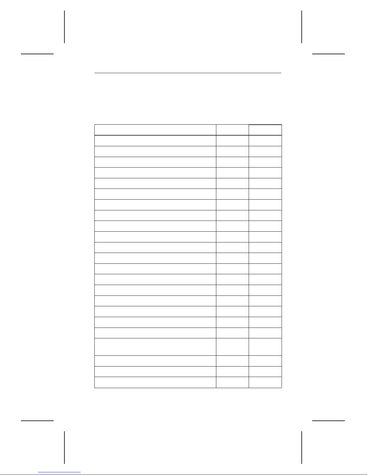
The following table serves as a quick reference for the drives’ performance specifications. These and other specifications are discussed in
“Specifications” on page 5.
Drive specification ST36450A ST35040A
9
Guaranteed capacity (Gbytes) (×10
Guaranteed sectors 12,594,960 9,782,640
Bytes per sector 512 512
Sectors per track 63 63
Logical read/write heads 15 15
Logical cylinders 13,328 10,352
Physical cylinders 6,536 6,536
Physical read/write heads 10 8
Physical discs 5 4
Areal density (Mbits per square inch) 928.8 928.8
bytes) 6.5 5.0
Data zones 19 19
Recording density (bits per inch) 138,011 138,011
Track density (tracks per inch) 6,730 6,730
Spindle speed (RPM) 5,397 5,397
Track-to-track se ek time (msec typical) 2.0 2.0
Average read seek time (msec typical) 9.5 9.5
Average write seek time (msec typical) 10.0 10.0
Full-stroke seek time (msec typical) 20 20
Average latency (msec) 5.58 5.58
Internal data-transfer rate
(Mbits per sec max) 63 to 116
63 to 116
External transfer rate (Mbytes per sec max) 16.6 16.6
Cache buffer (Kbytes) 512 512
ECC on-the-fly (bits) 65 65
continued
Page 12
4 Medalist Pro 6450/5040 Product Manual, February 1997
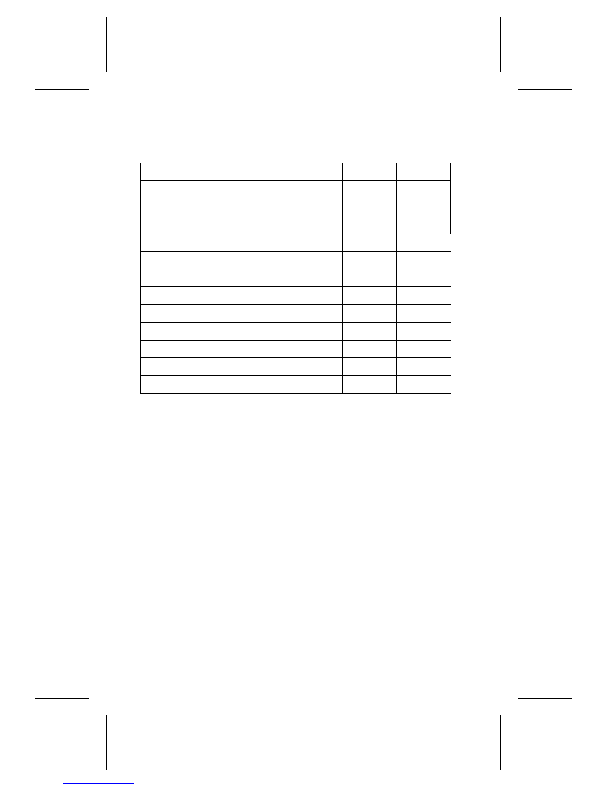
continued from previous page
Drive specification ST36450A ST35040A
Height (inches max) 1.027 1.027
Width (inches max) 4.023 4.023
Depth (inches max) 5.787 5.787
Typical weight (lb) 1.5 1.5
Spinup current (max) 3.0A 3.0A
Seek power (typical) 9.8W 9.8W
Read/Write power and current (typical) 7.8W 7.8W
Idle total power (typical) 7.8W 7.8W
Standby/Sleep total power (typical) 2.0W 2.0W
Voltage tolerance (including noise): +5V ± 5% ± 5%
Voltage tolerance (including noise): +12V ± 5% ± 5%
Operating temperature (°C) 5 to 55°C 5 to 55°C
Page 13

Medalist Pro 6450/5040 Product Manual, February 1997 5
1.0 Specifications
1.1 Formatted Capacity
Medalist Pro drives are low-level formatted at the factory. You cannot
low-level format them.
These drives suppo rt cylinder-he ad-sec tor (CHS) and log ical-bloc k addre ssing (LBA) translatio n modes . You can use the Ident ify drive (EC
to verify the address modes the drives support, the number of cylinders,
sectors per track, t ot al num ber of sectors, heads and other paramete rs . Th e
Identify drive para meters are listed in Sect ion 3.2.1 on pa ge 29.
Notes:
. DOS cannot acce ss more than 2. 147 G bytes per partition. Yo u
1
must create multiple pa rtitions to access the drive’s full ca pacity.
One Mbyte equals one million bytes.
2.
. If the system BIOS does not support more than 4,096 cylin-
3
ders, it can cause the computer to hang during startup, or it
can truncate or wrap the cylinders. To resolve this issue, the
system BIOS needs to be modified: the cylinder register or
variable must be increased from 12-bits to 16-bits to accommodate more than 4,096 cylinders.
) comma nd
H
1.1.1 Standard Configuration
ST36450A CHS LBA
Cylinders 13,328
Heads 15
Sectors 63
Guaranteed sectors 12,594,960 12,594,960
Guaranteed capacity (Gbytes) 6.4 6.4
ST35040A CHS LBA
Cylinders 10,352
Heads 15
Sectors 63
Guaranteed sectors 9,782,640 9,782,640
Guaranteed capacity (Gbytes) 5.0 5.0
Page 14

6 Medalist Pro 6450/5040 Product Manual, February 1997
1.2 Physical organization
ST36450 ST35040A
Read/write heads 10 8
Discs 5 4
1.3 Functional specifications
ST36450A ST35040A
Interface ATA ATA
Recording method PRML (8/9 ) PRML (8/9)
External data burst transfer rate:
DMA mode 2 (Mbytes per sec)
PIO mode 4 (Mbytes per sec)
Internal data-transfer rate
(Mbits per sec)
Spindle speed (RPM) 5,397 ± 0.5% 5,397 ± 0.5%
Cache size (Kbytes) 512 512
Logical cylinders 13,328 10,352
Physical cylinders 6,536 6,536
Bytes per sector 512 512
Areal density (Mbytes/sq. in) 928.8 928.8
Data zones 19 19
Recording density, max (BPI) 138,011 138,011
Track density (TPI) 6, 730 6,730
16.6
16.6
63 to 116 63 to 116
16.6
16.6
See Figure 10 on page 39 for multiword DMA timing specifi ca-
Note.
tions. See Figure 8 on page 37 and Figure 9 on page 38 for PIO
timing specifications.
Page 15

Medalist Pro 6450/5040 Product Manual, February 1997 7
1.4 Physical dimensions
The mounting dimensions are shown in Figure 6 on page 23.
Height, max 1.027 inch (26.09 mm)
Width, max 4.025 inches (102.2 mm)
Depth, max 5.787 inches (146.99 mm)
Weight 1.5 lb (0.68 Kg)
1.5 Seek time
Seek value is the interval between the time the actuator begins to move
and the time the head has settled over the target track. Seek time is a
true statistical average of at least 10,000 measurements of seek time.
All measurements are taken under nominal conditions of temperature
and voltage with the drive mounted horizontally. The specifications in the
table below are defined as follows:
• Track -to-track seek time is the average of all possible s ingle-track
seeks in both directions.
• Average seek time is measured by executing seeks in both directions
between random cylinders.
• Ful l-stroke seek time is half the time needed to seek from track 0 to
the maximum track and back to track 0.
Track-to-track
seek time (typ)
2.0 msec seek
2.5 msec read
3.5 msec write
Host overhead varies between systems and cannot be specified.
Note.
Drive internal overhead is measured by issuing a no-motion seek.
Overhead is typically less than 0.5 msec.
Average/typical
seek time
9.5 msec read
10.0 msec write
Full-stroke
seek time (typ)
20.0 msec seek
22.0 msec read
23.5 msec write
Average
latency
5.58 msec
1.6 Multisegmented cache buffer
The Medalist Pro ST36450A and ST35040A drives are available with a
512-Kbyte, multisegmented cache buffer that improves performance by
reducing access times.
Read look-ahead.
logical sectors, after the last requested sector, into a buffer befor e the
computer requests the additional sectors. The c ache buffer stor es data
The drive uses the read segments to store additional
Page 16
8 Medalist Pro 6450/5040 Product Manual, February 1997
from the start of a read until the buffer segment is full or until another
command is received.
Write immediate
. The drive uses the write segment to store write
commands and data. After the drive receives all of the data for the
command, it issues a write complete. Then, the drive writes the data to
the disc.
Write merging.
The drive accepts contiguous write commands and
executes them as one command.
1.7 Start and stop tim es
Within 20 seconds after power is applied, the drive is ready. Within 15
seconds after power is removed, the drive spindle stops rotating.
1.8 Typical power-up and power-down sequence
This section describes typical power-up and power-down sequences to
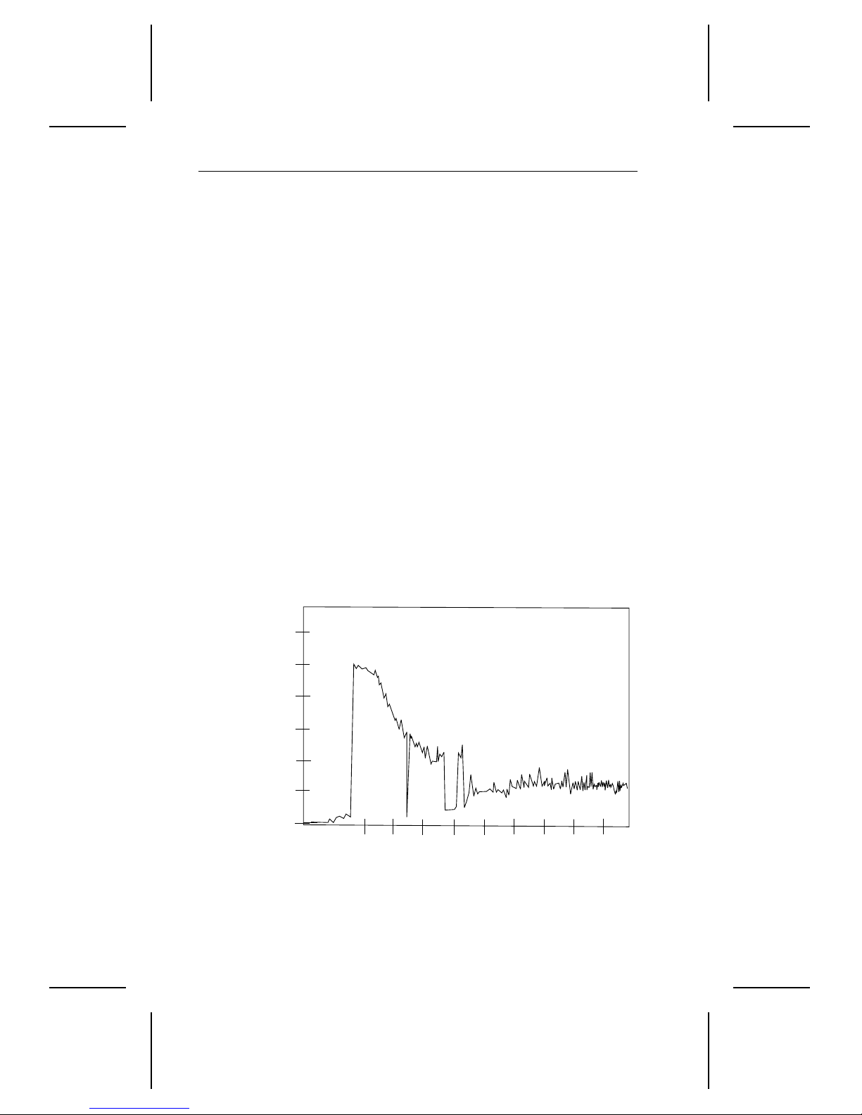
assist you in evaluating the dri ve’s performance. They are not performance specifications. A typical startup current profile is shown in Figure 1.
Startup current profiles are unique for each drive.
Current (Amps)
3.5
3.0
2.5
2.0
1.5
1.0
0
0
Figure 1. Typical startup current p rofi l e
4
2
6
8
10
12
Time (seconds)
14
16
18
Page 17

Medalist Pro 6450/5040 Product Manual, February 1997 9
1.9 Power-up sequence
Power is applied to the drive.
1.
When power is applied, the LED stays on for about 1 second.
2.
The spindle motor reaches operating speed in about 4 seconds.
3.
The magnetic actuator-lock releases the actuator.
4.
The drive achieves final speed-control lock.
5.
The heads position over track 0 and the drive is ready.
6.
1.9.1 Power-down sequence
Caution.
The power is turned off.
1.
Within 15 seconds, the drive spindle stops rotating.
2.
The read/write heads automatically move to the landing zone, which
3.
is inside the maximum data cylinder.
The magnetic actuator-lock mechanism locks the arm. This completes
4.
the power-down sequence.
Do not move the drive until the motor has come to a complete
stop.
1.10 Auto-park
During power-down, the read/write heads automatically move to the
landing zone. The heads park inside the maximum data cylinder and the
magnetic actuator-lock engages. When power is applied, the heads
recalibrate to track 0.
1.11 Power specifications
1.11.1 Power ma nagement
The drive supports Active, Idle and Standby power-management modes.
The power-management commands the drive supports are listed in the
table on page 27. The table on page 11 shows the average typical power
consumption rates for each power-management mode. The test criteria
for each mode is defined below. The Idle and Standby timers are disabled
at the factory.
Page 18

10 Medalist Pro 6450/5040 Product Manual, February 1997
All measurements were taken at t he dr ive power c onnector. A true RMS
meter is used to measure all modes except Standby. A DMM is used for
Standby measurements.
1.11.1.1 Acti ve mode
During the Active mode, the drive is involved in spinup, seeking or
read/write activities. The table on page 11 shows the typical power-consumption rates for these activities.
•
Spinup
and brings the spindle and discs up to operating speed. Power in this
mode is defined as the peak power after starting spinup.
•
Seek.
read/write heads are moved to a specific location on the disc surface
in preparation for reading from or writing to the disc. Read/write
electronics are powered down but servo electronics are active. Typical
power is defined as the power average of executing random seeks
with a 2-revolution (22.2 msec) dwell between Seek commands.
•
Read/write.
electronics are activated and t he servo is on track. The driv e reads
from or writes to the disc.
. The drive enters the Spinup mode from the Standby mode
The drive enters the Seek mode from the Idle mode. The
Read/write mode is entered from Idle mode. Read/write
1.11.1.2 Idle mode
The Idle mode is entered 1 minute after the last disc I/O activity. The motor
is up to speed and the actuator is repositioned once every minute. This mode
uses an algorithm that minimizes head media interface stresses. The drive
can enter Idle mode from either Active or Standby mode.
1.11.1.3 Standby mode
The spindle is stopped, t he heads are parked in the landing zone, the
actuator is latched and some of the drive electronics are powered down.
When recovering from Standby or Sleep mode, you must allow
Note.
the drive to post ready before reporting a timeout. The drive can
take up to 20 seconds to post ready. In a master and slave
configuration, the master can wait up to 31 seconds for the slave
to complete diagnostics before posting ready.
1.11.1.4 Sleep mode
The sleep mode implementation is the same as Standby mode.
Page 19
Medalist Pro 6450/5040 Product Manual, February 1997 11
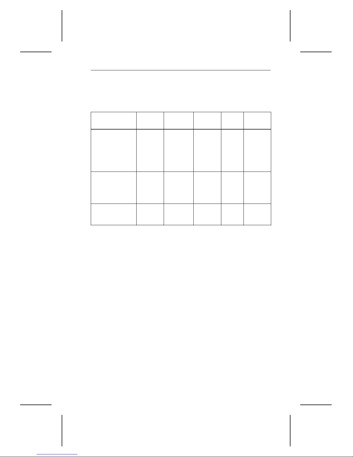
1.11.2 Power consumption
In the table below, the values apply at the drive power connector. Current
was measured with an RMS DC ammeter.
Read/
Spinup Seek
Current at +12V
write Idle Standby
Amps max
RMS amps typ
Watts typ
Current at +5V
RMS amps typ
Watts typ
Power
Total watts typ
1.12 Input noise
Voltage tolerance
(including noise)
Input noise frequency
(max)
Input noise
(max, peak-to-peak)
3.0A — — — —
— 0.68 0.50 0.50 0.02
— 8.1 6.0 6.0 0.25
— 0.36 0.36 0.36 0.35
— 1.8 1.8 1.8 1.75
— 9.8W 7.8W 7.8W 2.0W
+5V +12V
± 5% ± 5%
25 MHz 25 MHz
100 mV 240 mV
1.13 Environmental specifications
1.13.1 Ambient temperature
Operating
Nonoperating –40° to 70°C (–40° to 158°F)
The system must provide sufficient airflow to maintain a
Note.
surface termperature of the aluminum base below 60°C.
5° to 55°C (41° to 122°F)
Page 20

12 Medalist Pro 6450/5040 Product Manual, February 1997
1.13.2 Temperature grad ient
Operating 20°C per hour (36°F per hour)
Nonoperating 25°C per hour (45°F per hour)
1.13.3 Altitude
Operating –1,000 ft. to 10,000 ft. (–305 m to 3,048 m)
Nonoperating –1,000 ft. to 40,000 ft. (–305 m to 12,192 m)
1.13.4 Relative humidity
Operating 8% to 80% noncondensing
Maximum wet bulb 29.4°C (85°F)
Maximum operating
gradient
Nonoperating 5% to 95% noncondensing
10% per hour
Maximum wet bulb 35°C (95°F)
1.14 Shock and vibration
All shock and vibration specifications apply when the drive is mounted
as recommended in Section 2.5 on page 22, with the input levels
measured at the drive mounting screws. Shock measurements are based
on an 11 msec, half sine wave shoc k pulse, not to be repeated m ore than
twice per second.
During normal operating shock and vibration, there is no phys ic al damage to the drive or performance degradation. During nonoperating shock
and vibration, the read/write heads are positioned in the landing zone.
During abnormal operating shock and vibration, there is no physical
damage to the drive, although performance may be degraded during the
shock or vibration episode. When normal operating shock levels resume,
the drive meets its performance specifications.
Operating Abnormal Nonoperating
Shock 2 Gs 10 Gs 75 Gs
5–22 Hz vibration 0.020-inch
displacement
22–350 Hz vibration 0.50 Gs — 2.00 Gs
—
0.081-inch
displacement
Page 21

Medalist Pro 6450/5040 Product Manual, February 1997 13
1.15 Acoustics
This table shows the overall A-weighted acoustic sound power and sound
pressure levels for the drives. All measurements are generally consistent
with ISO document 7779. Acoustic measurements are taken under
essentially free-field conditions over a reflecting plane. The drive is
oriented with the top cover up for all tests.
Overall A-weighted Value Idle Seek
Sound power, typ (bels) 3.6 4.3
Sound power, max (bels) 4.0 4.4
Sound pressure, typ (dBA) 30 34
Sound pressure, max (dBA) 33 34
1.16 Reli ability
Read error rates are measured with automatic retries and data correction
with ECC enabled and all flaws reallocated. The mean time between
failures (MTBF) is measured at nominal power at sea level and an
ambient temperature of 25°C.
Nonrecoverable read errors 1 per 10
Seek errors 1 per 10
13
bits transferred
7
physical seeks
Contact start/stops 30,000 cycles
MTBF 300,000 power-on hours
Service life 5 years
1.17 Agency listings
This drives are listed by agencies as follows:
• Recognized in accordance with UL478 and UL1950
• Certified to CSA C22.2 No. 220-M1986 and CSA C22.2 No. 950
• Certified to VDE 0805/05.90 and EN 60950/1.88 as tested by VDE
Page 22

14 Medalist Pro 6450/5040 Product Manual, February 1997
1.18 Electromagnetic Compliance for the European
Union
If this model has the CE Marking, it complies with the European Union
requirements of the Electromagnetic Compatibility Directive 89/336/EEC
of 03 May 1989 as amended by Directive 92/31/EEC of 28 April 1992
and Directive 93/68/EEC of 22 July 1993.
Seagate uses an independent laboratory to confirm compliance to the
above directives. The drive was tested in a representative system for
typical applications. T he selected system r epresents the most popular
characteristics for test platforms. The system configurations include:
• 486, Pentium, and PowerPC microprocessors
• 3. 5-i nch floppy disc drives
• Key board
• Monitor/display
Although the test system with this Seagate model complies to the
directives, we cannot guarantee that al l systems will comply. The computer manufacturer or system integrator shall c onfirm EMC compliance
and provide CE Marking for their product. The drive is not meant for
external use (without properly des igned enclosure, shielded I/O cable,
etc.) and that a terminator should be used on all unused I/O ports.
1.19 FCC verification
The Medalist Pro ATA interface drives are intended to be contained
solely within a personal computer or s imilar enclosure (not at tached to
an external device). As such, a drive is c onsidered to be a subassembly
even when individually marketed to the customer. As a subassembly, no
Federal Communications Commission authorization, verification or certification of the device is required.
Seagate Technology, Inc. has tested these drives in an enclosure as
described above to ensure that the total assembly (enclosure, disc
drives, motherboard, power supply, etc.) does comply with the limits for
a Class B computing device, pursuant to Subpart J of Part 15 of the FCC
rules. Operation with noncertified assemblies is likely to result in interference to radio and television reception.
Radio and television interference.
radio frequency energy and, if not installed and used in strict accordance
with the manufacturer’s instructions, may cause interference to radio and
television reception.
This equipment is designed to provide reasonable protection against
This equipment generates and uses
Page 23

Medalist Pro 6450/5040 Product Manual, February 1997 15
such interference in a residential installation. However, there is no
guarantee that interference will not occur in a particular installation. If this
equipment does cause interference to radio or television, which can be
determined by turning the equipment on and off, you are encouraged to
try one or more of the following corrective measures:
• Reorient the receiving antenna.
• Move the device to one side or the other of the radio or TV.
• Move the device farther away from the radio or TV.
• Plug the equipment into a different outlet so that the receiver and
computer are on different branch outlets.
If necessary, you should consult your dealer or an experienced radio/television technician for additional suggesti ons. You may find helpful the
following booklet prepared by the Federal Communications Commission:
How to Identify and Resolve Radio-Television Interference Problems
This booklet is available from the Superintendent of Documents, US
Government Printing Office, Washington, DC 20402. Refer to publication
number 004-000-00345-4.
This digital apparatus does not exceed the Class B limits for radio
Note.
noise emissions from computer equipment as set out in the radio
interference regulations of the Canadian Department of communications.
Le présent appareil numérique n′émet pas de bruits radioélectri-
ques dépassant les limites applicables aux appareils numériques
de Classe B prescrites dans le règlement sur le brouillage radioélectrique édicté par le Ministère des Communications du
Canada.
.
Page 24

16 Medalist Pro 6450/5040 Product Manual, February 1997
Sicherheitsanleitung
Das Gerrät ist ein Einbaugerät, das für eine maximale Umgebung-
1.
stemperatur von 50°C vorgesehen ist.
Zur Befestigung des Laufwerks werden 4 Schrauben 6-32 UNC-2A
2.
benötigt. Bei seitlicher Befestigung darf die maximale Länge der
Schrauben im Chassis nicht mehr als 5,08 mm und bei Befestigung
an der Unterseite nicht mehr als 5,08 mm betragen.
Als Versorgungsspannugen werden benötigt:
3.
+5V æ 5% 0.55A
+12Væ 5% 0.35A (2. 0A fur ca . 30 Sek. fur ± 10%)
Die Versorgungsspannung muss SELV entsprechen.
4.
Alle Arbeiten an der Festplatte dürfen nur von ausgebildetem Serv-
5.
icepersonal durchgeführt werden. Bitte entfernen Sie nic ht die Aufschriftenschilder des Laufwerkes.
. Der Einbau des Laufwerkes muss den Anforderungen gemäss DIN
6
IEC 950 VDE 0805/05.90 entsprechen.
Page 25

Medalist Pro 6450/5040 Product Manual, February 1997 17
2.0 Configuring and mounting the drive
This section contains the specifications and instructions for configuring
and mounting the drive.
2.1 Handling and static-discharge precautions
After you unpack the drive, and before you install it in a system, be careful
not to damage it through mishandling. Observe the f ollowing standard
handling and static-discharge precautions:
Caution:
• Keep the drive in its static-shielded bag until you are ready to complete
the installation. Do not attach any cables to the drive while it is in its
static-shielded bag.
• Before handling the drive, put on a grounded wris t strap, or ground
yourself frequently by touching the metal chassis of a computer that
is plugged into a grounded outlet. Wear a grounded wrist strap
throughout the entire installation procedure.
• Handle the drive by its edges or frame only.
• The drive is extremely fragile—handle it with care. Do not press down
on the drive top cover.
• Always rest the drive on a padded, antistatic surface until you mount
it in the computer.
• Do not touch the connector pins or the printed circuit board.
• Do not remove the factory-installed labels from the drive or cover them
with additional labels. Rem oval voids the warranty. Some factory-installed labels contain information needed t o service the driv e. Other
labels are used to seal out dirt and contamination.
Page 26
18 Medalist Pro 6450/5040 Product Manual, February 1997
2.2 I/O cable and connector
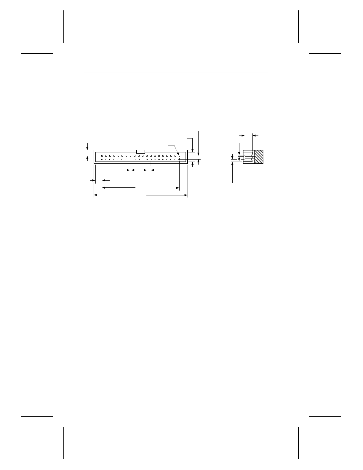
The drive uses a 40-pin, male I/O connector with two rows of twenty pins
each and a notch for keying. Pin 20 is removed for keying purposes. A
drawing of the I/O connector is shown in Figure 2. Pin 1 is located near
the 4-pin power connector when the I/O connector is mounted.
0.70 ± 0.010
0.100 ± 0.010
0.235 ± 0.025
pin 1
0.230 ± 0.003
0.025 ± 0.002
0.025
± 0.002
0.160
1.90
2.00
Figure 2. ATA inte rface connector
0.100 typ
0.070 ± 0.010
The table below lists recommended parts for the mating connector. You
can use equivalent parts.
Part Description 3M part number
Connector 40-pin 3M-3417-7000
Connector 40-pin 3M-3448-2040
Flat cable AWG28 (stranded) 3M-3365-40
To ensure the integrity of your data, use a 40-connector, nonshielded I/O
cable with a maximum length of 18 inches (46 centimeters).
2.3 Power connector
The drive uses a standard 4-pin, male power connector. We recommend
the following part number or their equivalents for the mating connector.
Part Description Part number
Connector Housing AMP 1-480424-0
Connector Pin (loose piece) AMP 60619-4
Connector Pin (reel) AMP 6117-4
Cable 18 AWG
Page 27
Medalist Pro 6450/5040 Product Manual, February 1997 19
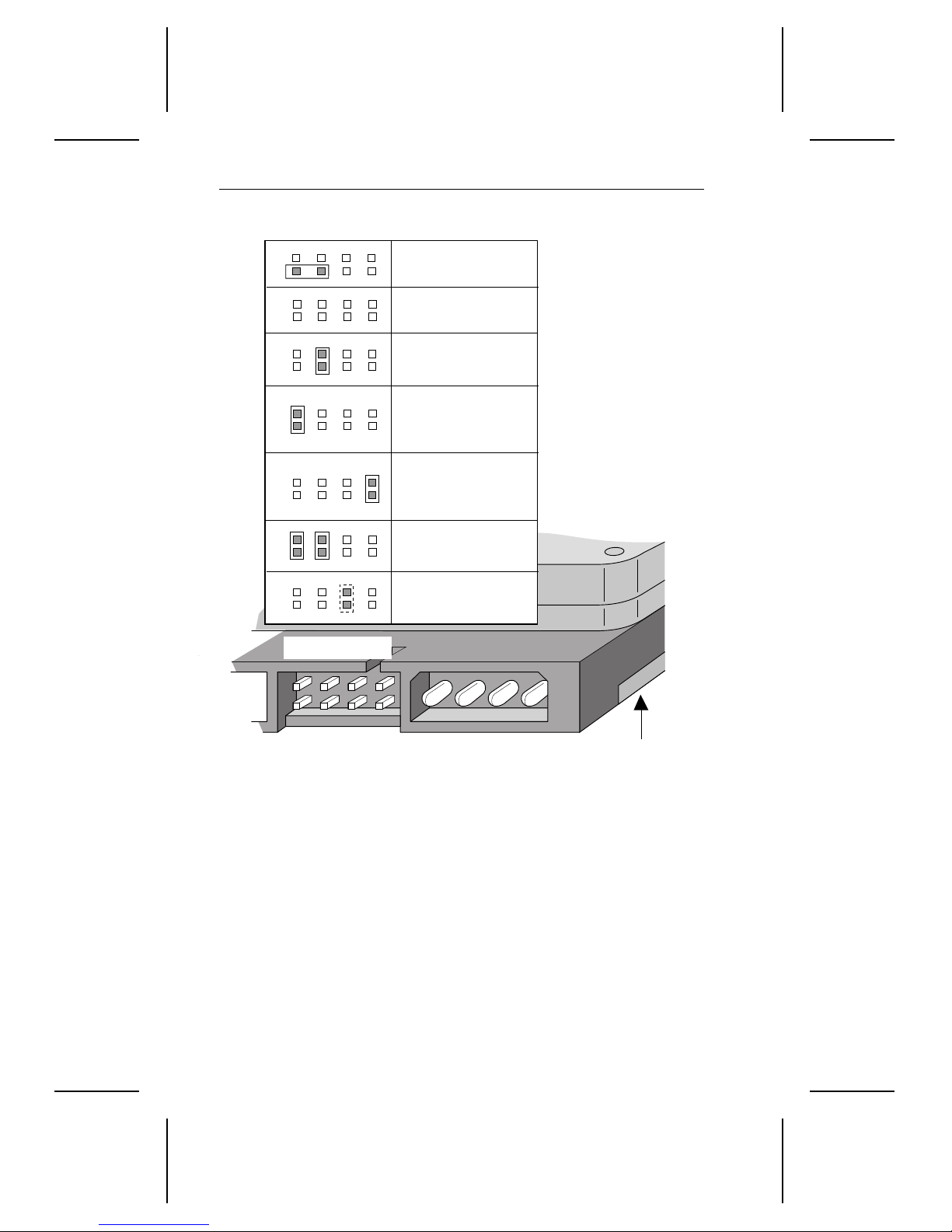
2.4 Options jumper block
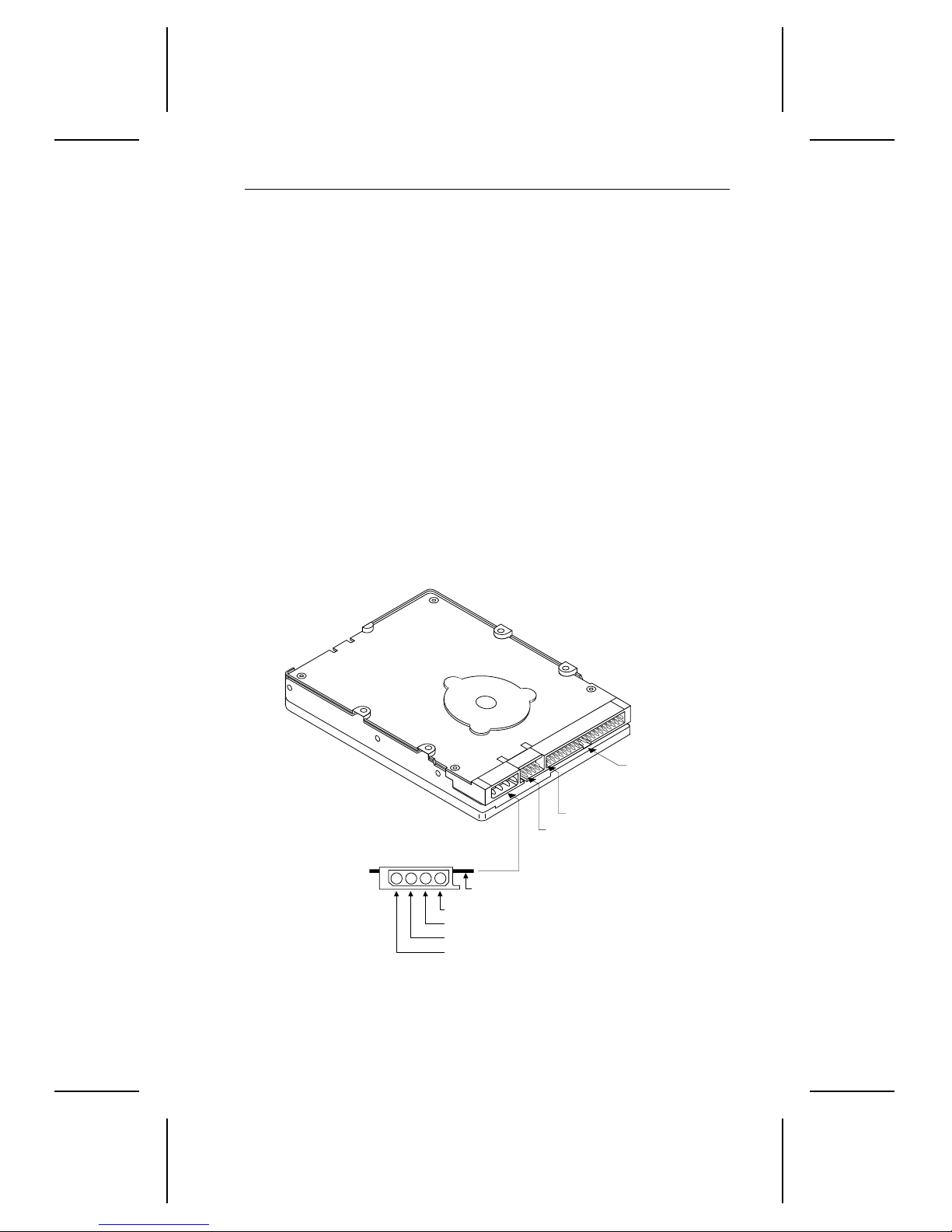
The options jumper block (J5), shown in Figure 3, is used to configure
the drives for operation. It is the 8-pin dual header between the I/O
connector and the power connector. Pin 1 is l ocated next to the power
connector and is farthest from the printed circuit board. It accepts
0.1-inch jumpers. The options jumper block is used to:
• Configure the drive for single-drive operation
• Configure the drive as master with an ATA-compatible slave
• Configure the drive as the slave
• Configure the drive for alternate capacity
• Configure the drive for cable select
• I nstall a remote LED
The jumper settings for these options are shown in Figure 4 on page 20.
The drive is shipped with a spare jum per att ached to pins 6 and 8. Use
this jumper to configure the drive.
Figure 3. Conne ct ors
Standard
power connector
3
1
4
2
+5V
+5V return
+12V return
+12V
Circuit board
Pin 1
(J5)
Pin 1
Interface
connector
Page 28
20 Medalist Pro 6450/5040 Product Manual, February 1997
Options jumper block (J5)
Spare
Jumper
One drive only
Drive is slave
Master with an
ATA-compatible
slave
Alternate Capacity
(AC)
Cable select
Remote LED
connection
1753
684
Figure 4. Confi gur at io n Set tings
2.4.1 Master/slave configuration
Use the following settings to configure the drive as master or slave.
One drive only.
operation. No jumpers are required for single-drive operation. The spare
jumper on pins 6 and 8 does not affect drive operation.
Drive as slave
Drive as master with an ATA-compatible slave.
pins 7 and 8.
. Place a jumper on pins 5 and 6.
2
The drive is configured at the factory for single-drive
Circuit Board
Place a jumper on
Page 29

Medalist Pro 6450/5040 Product Manual, February 1997 21
2.4.2 Alternate capacity jumper
This jumper lowers the drive capacity by setting the default translation to
4.092 cylinders. Some BIOSs that only auto-detect may require this
jumper. Place a jumper on pins 1 and 2 of the J5 options jumper block
to enable this option. When installing this jumper, you may need thirdparty partitioning software to achieve full capacity of the drive.
2.4.3 Cable-select option
Computers that use cable-select determine the master and slave drives
by selecting or deselecting pin 28, CSEL, on the interface bus. Master
and slave drives are determined by their physical position on the cable.
• The drive plugged into the I/O connector that carries the CSEL signal
is the master.
• The drive plugged into the I/O connector that does not carry the CSEL
signal is the slave.
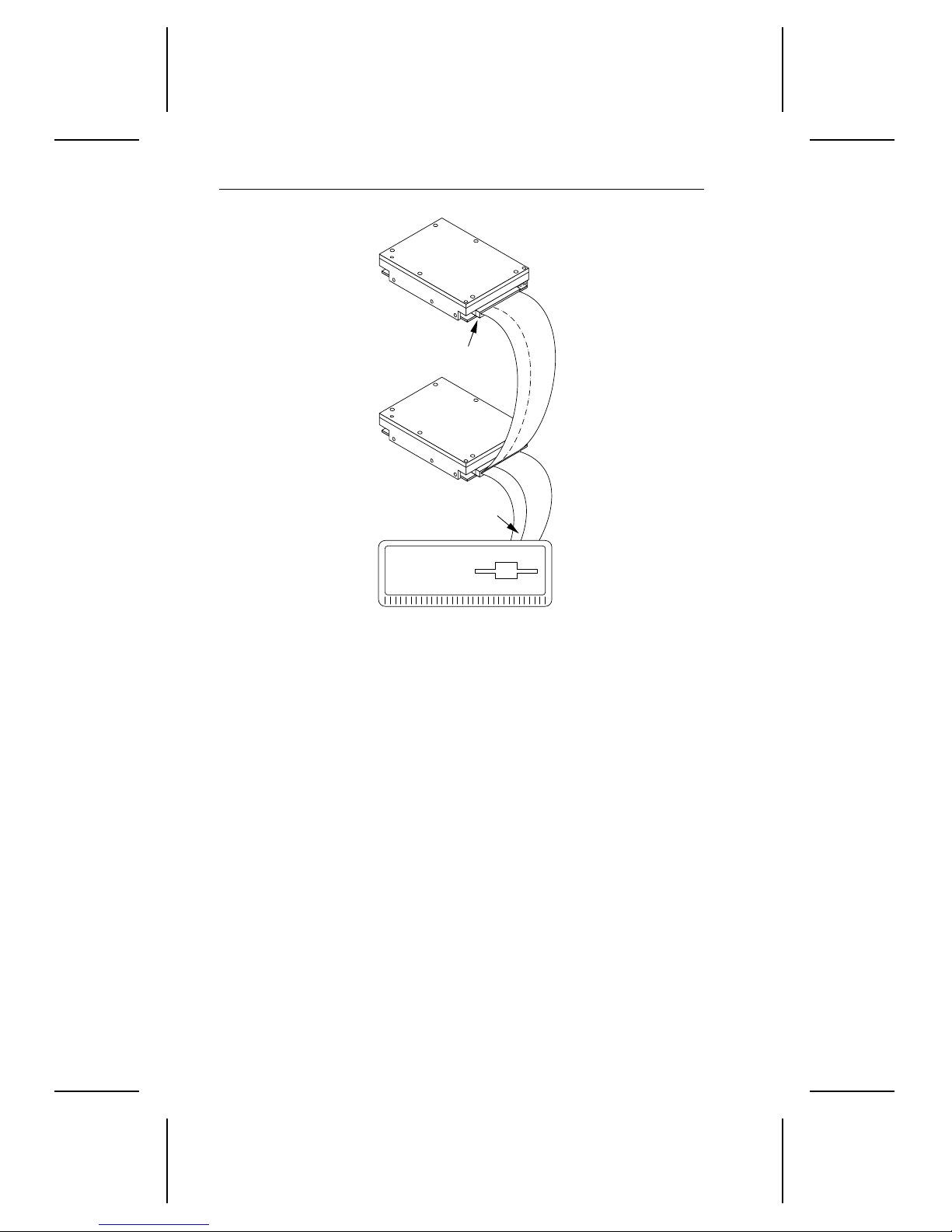
To configure the drives for computers that use cable select:
• I nstall jum pers on pins 5 and 6 and pins 7 and 8 as shown in
Figure 4 on page 20.
• Connect the drives to the cable as shown in Figure 5 on page 22.
2.4.4 Remote LED
You can connect a remote LED to pins 3(–) and 4(+) of the options jumper
block (J5). Do not install a shunt jumper on these pins.
Because the jumper block uses a 0.1-inch connector, you may need to
replace the current connector. Use Seagate connector part number
10562-001 or an equivalent.
Page 30
22 Medalist Pro 6450/5040 Product Manual, February 1997
Slave
CSEL not carried
to pin 28 of
this connector
Master
Pin 28 grounded
at computer
Computer
Figure 5. Conne ct in g cabl e- selected drives
2.5 Mounting the drive
You can mount the drive in any orientation.
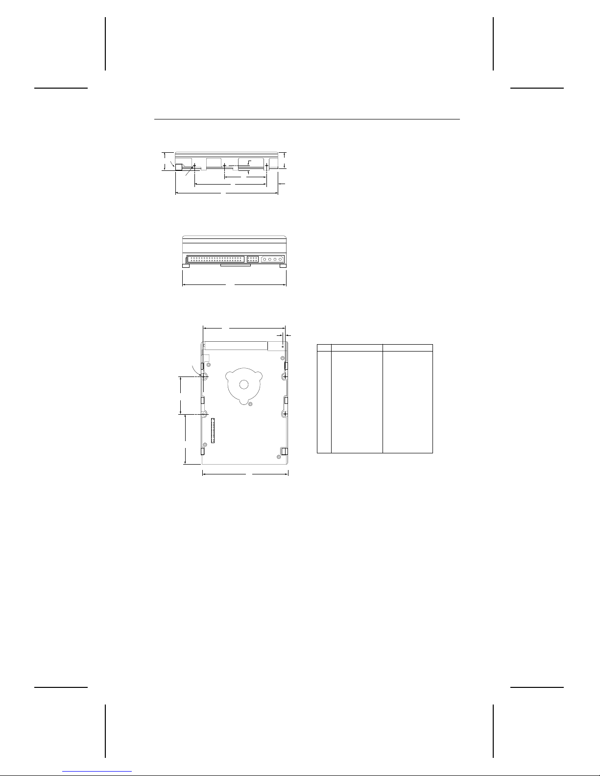
Use the set of mounting guidelines below that are appropriate to the type
of mounting holes used: either bottom mounting holes or side mounting
holes. Refer to Figure 6 on page 23 for mounting dimensions.
Bottom mounting holes.
mounting holes as shown in Figure 6.
Caution.
Do not insert the bottom mounting screws more than
0.20 inches (6 turns) into the drive frame.
Side mounti ng holes.
available side mounting holes as shown in Figure 6. Use two mounting
holes on each side of the drive.
Caution.
Do not insert the side mounting screws more than 0.20
inches (6 turns) into the drive frame. If you use a screw that is
too long, you risk damaging the drive’s circuit board.
Insert four 6-32 UNC screws in the four bottom
Use four 6-32 UNC screws in four of the six
Page 31
Medalist Pro 6450/5040 Product Manual, February 1997 23
[3]
C
[1]
A
[2]
H
K
G
D
F
B
J
[4] M
K
E
Notes.
[1]
Mounting holes three on each side, 6-32 UNC.
Max screw length into side of drive 0.15 in. (3.81
mm). Screw tightening torque 6.0 in-lb (0.675
NM) max with minimum thread engagement of
0.12 in. (3.05 mm).
Mounting holes four on bottom, 6-32 UNC. Max
[2]
screw length into bottom of drive 0.15 in. (3.81
mm). Screw tightening torque 6.0 in-lb (0.675 NM)
max with minimum thread engagement of 0.12 in.
(3.05 mm).
Power and interface connectors can extend past
[3]
the “A” dimension by 0.040 in. (1.02 mm).
[4]
Centerline of pad for Pin 1 of power connector.
[5]
Dimensions to Pin 1 of each connector are
nominal values.
Dimension Table
Inches
± 0.010
5.74
A
B
C
D
E
F
G
H
J
K
L
M
± 0.010
4.00
+ 0.021
1.00
– 0.009
± 0.010
2.362
± 0.020
0.620
± 0.010
4.000
+ 0.010
0.250
– 0.005
± 0.010
1.750
± 0.010
3.750
± 0.010
1.00
± 0.010
4.000
0.143
[5] [5]
Millimeters
145.80
101.60
+ 0.53
25.40
60.00
15.75
101.60
6.35
44.45
95.25
25.4
101.6
3.63
± 0.25
± 0.25
– 0.22
± 0.25
± 0.50
± 0.25
+ 0.25
– 0.12
± 0.25
± 0.25
± 0.25
± 0.25
L
Figure 6. Mount i ng dimensions
Page 32

24 Medalist Pro 6450/5040 Product Manual, February 1997
Page 33

Medalist Pro 6450/5040 Product Manual, February 1997 25
3.0 ATA Interface
The drives use an ATA-3 interface. The interface complies with
ATA (AT Attachment) Interface X3T10 Rev. 6.0
Extension for Local Bus Attachments, Rev. 2. 0
drives Data for drives Under 8 GB
support are listed on pages 27 and 28. Commands and features with
specific applications for these drives are also discussed in this section.
The ATA interface consists of single-ended, TTL-compatible receivers
and drivers that use an asynchronous interface protocol. The drivers can
sink up to 24 mA and drive a load up to 300 pF. The integrity of the ATA
interface is affected by the interface cable. It is designed to support a
40-conductor, nonshielded interface cable with a maximum length of 18
inches (46 centimeters).
. The ATA commands that the drives
;
SFF 8011: ATA Timing
and SFF 8019:
ANSI
Identify
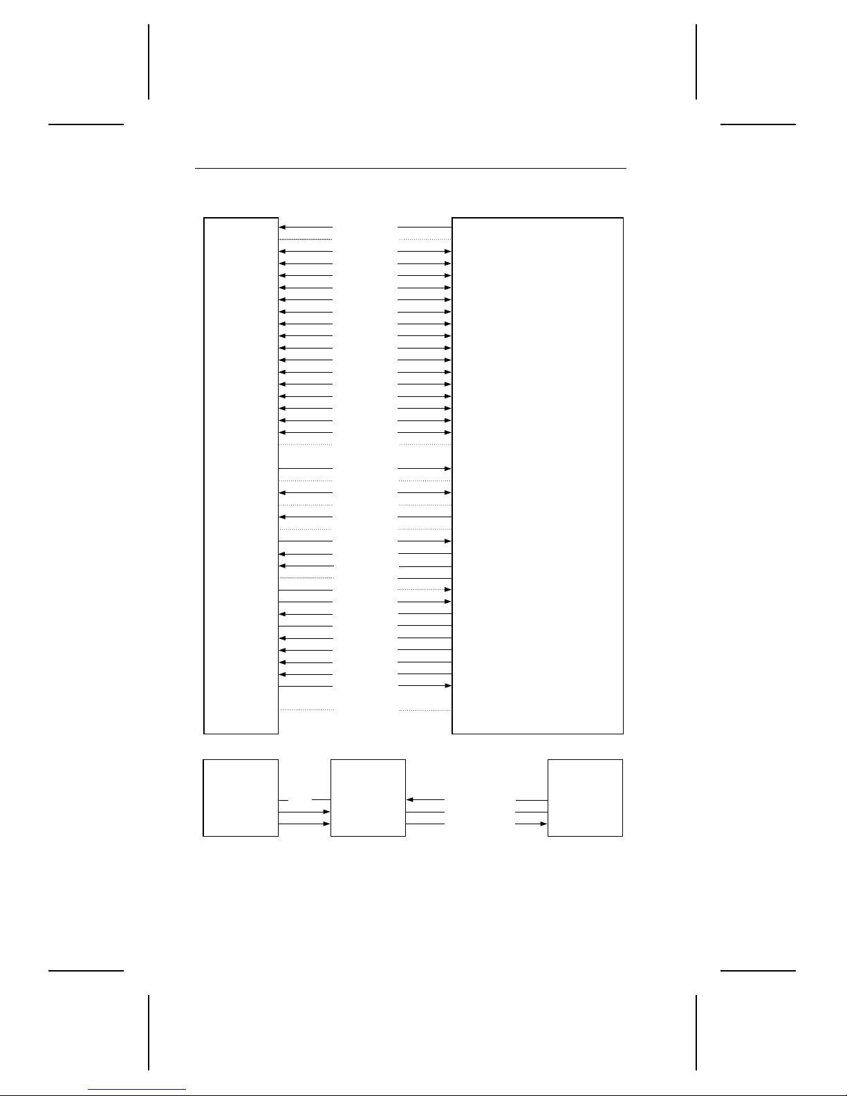
3.1 ATA Interface connector pin assignments
The signal name and signal direction for each I/O connector pin is shown
in Figure 7 on page 26. See the
Manual
each pin.
Signal names are shown in upper-case letters. If the signal name is
followed by a minus sign (–), the signal is active low. Otherwise, the signal
is active high.
, publication number 36111-
Seagate ATA Interface Reference
, for a complete description of
xxx
Page 34
26 Medalist Pro 6450/5040 Product Manual, February 1997
Drive
1
2
3
4
5
6
7
8
9
10
11
12
13
14
15
16
17
18
19
20
21
22
23
24
25
26
27
28
29
30
31
32
33
*34
35
36
37
38
*39
40
*
Drive-to-drive signals
Reset–
Ground
DD7
DD8
DD6
DD9
DD5
DD10
DD4
DD11
DD3
DD12
DD2
DD13
DD1
DD14
DD0
DD15
Ground
(removed)
DMARQ
Ground
DIOW–
Ground
DIOR–
Ground
IORDY
CSEL
DMACK–
Ground
INTRQ
IOCS16–
DA1
PDIAG–
DA0
DA2
CS1FX–
CS3FX–
DASP–
Ground
Host
1
Host Reset
2
Ground
3
Host Data Bus Bit 7
4
Host Data Bus Bit 8
5
Host Data Bus Bit 6
6
Host Data Bus Bit 9
7
Host Data Bus Bit 5
8
Host Data Bus Bit 10
9
Host Data Bus Bit 4
10
Host Data Bus Bit 11
11
Host Data Bus Bit 3
12
Host Data Bus Bit 12
13
Host Data Bus Bit 2
14
Host Data Bus Bit 13
15
Host Data Bus Bit 1
16
Host Data Bus Bit 14
17
Host Data Bus Bit 0
18
Host Data Bus Bit 15
19
Ground
(No Pin)
20
21
DMA Request
22
Ground
23
Host I/O Write
24
Ground
25
Host I/O Read
26
Ground
27
I/O Channel Ready
28
Cable Select
29
DMA Acknowledge
30
Ground
31
Host Interrupt Request
32
Host 16 Bit I/O
33
Host Address Bus Bit 1
34
Passed Diagnostics
35
Host Address Bus Bit 0
36
Host Address Bus Bit 2
37
Host Chip Select 0
38
Host Chip Select 1
39
Drive Active/
Drive 1 Present
40
Ground
Drive 1
(slave)
28
34
39
Figure 7. ATA inte rface connector pin assi gnm ent s
NC
Drive 0
(master)
28
34
39
CSEL
PDIAG
DASP–
Host
–
28
34
39
Page 35
Medalist Pro 6450/5040 Product Manual, February 1997 27
3.2 Command set
This section lists all of the ATA commands the drives use. Only the
commands with unique implementation for the dri ves are discussed in
this manual. For information about the ATA interface, refer to
Draft X3T10.2008D Rev. 6, Information Technology—AT Attachment-3
Interface ATA-3
features is provided in
,
xxx
Small Form Factor Specification, SFF-8011 Rev 1.1, September 18,
, and
1993
January 8,1996, Revision 1.0, Preliminary Document
The table below lists all commands implemented in the drives. It uses
the following abbreviations:
FR Features register
SC Sector Count register
SN Sector Number register
CY Cylinder register
DH Drive/Head register
n This register does not contain a valid parameter for this
command.
y This regi ster contains a valid parameter for this command. In
the Drive/Head register, both the drive and head parameters
are valid for this command.
D The Drive/Head register contains a valid drive parameter for
this command. The head parameter is not valid for this
command.
Read DMA, Read Long, Read Sector, Read Verify Sector, Write
Note.
DMA, Write Long and Write Sector support with retry and without
retry commands.
. Additional information about the drive commands and
Seagate ATA Interface Reference Manual, 36311-
Small Form-Factor Committee Specification Draft SFF-8055i,
.
Working
Command name
Active and Set Idle Timer FB n y n n D
Active Immediate F9 nnnnD
Check Idle Mode FD n y n n D
Check Power Mode 98, E5 n y n n D
Execute Drives Diagnostic 90 nnnnD
continued
Command
code (in hex)
Parameters used
FR SC SN CY DH
Page 36
28 Medalist Pro 6450/5040 Product Manual, February 1997
continued from previous page
Command name
Command
code (in hex)
Parameters used
FR SC SN CY DH
Identify drives EC nnnnD
Idle 97, E3 n y n n D
Idle and Set Idle Timer FA n y n n D
Idle Immediate 95, F8, E1 nnnnD
Initialize Drive Parameters 91 n y n n y
Read DMA C8, C9 — yyyy
Read Long 22, 23 n yyyy
Read Multiple C4 n yyyy
Read Sector 20, 21 n yyyy
Read Sector Buffer E4 nnnnD
Read Verify Sector 40, 41 n yyyy
Recalibrate 1X nnnnD
Seek 7X n n y y y
Set Features E F y n n n D
Set Multiple Mode C6 n y n n D
Sleep 99, E6 nnnnD
S.M.A.R.T. B0 y y n y y
Standby 96, E2 nnnnD
Standby Immediate 94, E0 nnnnD
Write DMA CA, CB —yyyy
Write Long 32, 33 n yyyy
Write Multiple C5 n yyyy
Write Sector 30, 31 nyyyy
Write Sector Buffer E8 nnnnD
Page 37
Medalist Pro 6450/5040 Product Manual, February 1997 29
3.2.1 Identify drive command (ECH)
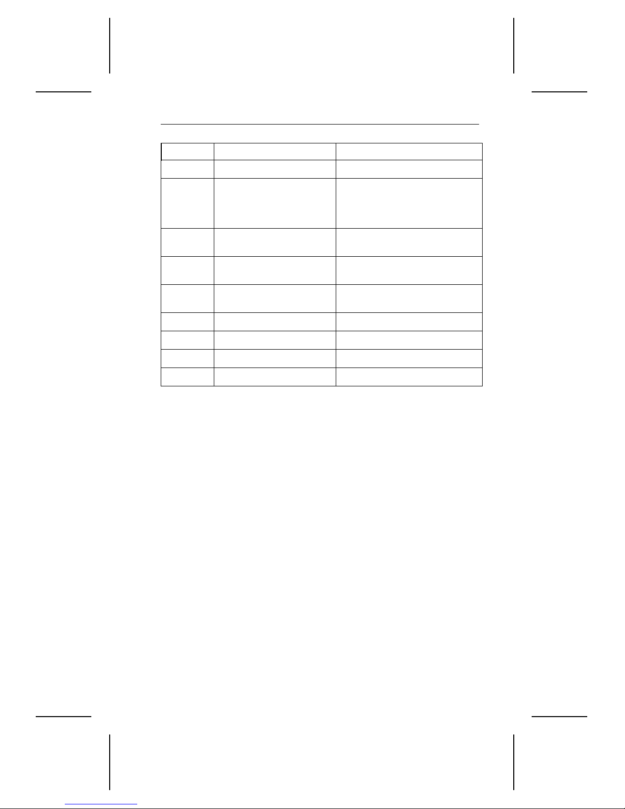
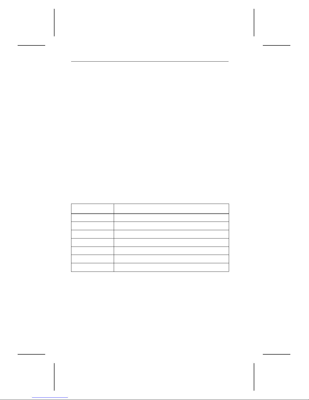
The Identify drive parameters for the drives are listed in the table below.
If the alternate capacity jumper is installed on the drive, the drive
Note.
capacity is reduced in Word 1 to 4.092 cylinders.
Word Description ST Value
0
Configuration 045A
H
1
2
3
4
5
6
7–9
10–19
20
21
22
23–26
27–46
47
Number of logical
cylinders
ST36450A = 13,328
ST35040A = 10,352
Reserved 0000
Number of logical heads 15
Vendor-specific 35,141
Vendor-specific 580
Number of logical sectors
63
per track
Vendor-specific 0000
Serial number (20 ASCII
drive-unique
characters)
Vendor-specific 3
Vendor-specific 224
ECC bytes (R/W Long) 0004
Firmware revision
H
drive-unique
(8 ASCII characters)
Model number (40 ASCII
characters)
Vendor-specific 8010
ST36450A
ST35040A
H
48
49
50
51
continued
Reserved 0000
Capabilities 0B01
0001H IORDY supported
Reserved 0000
PIO data-transfe r cycle
0200
timing mode
H
H
Page 38
30 Medalist Pro 6450/5040 Product Manual, February 1997
continued from previous page
Word Description ST Value
52
Obsolete 0200
H
53
54
55
56
57–58
59
60–61
62
63
64
65
66
67
68
Current valid 0003
0001H words 54–58, 64–70
valid
Number of current logical
cylinders
Number of current logical
ST36450A = 13,328
ST35040A = 10,352
15
heads
Number of current
63
sectors
Current capacity in
sectors (CHS)
= Current setting for
xx
H
ST36450A = 12,594,960
ST35040A = 9,782,640
0000s
number of sector that can
be transferred per
interrupt on Read/Write
Multiple command
Total number of useraddressable LBA sectors
ST36450A = 12,594,960
ST35040A = 9,782,640
Obsolete 0000
Multiword DMA transfer
mode active
0107
Mode 0 is active
Modes 0, 1, and 2 supported
Advanced PIO transfer
mode supported
Minimum multiword DMA
0003
Modes 3 and 4 supported
120 nsec
transfer cycle time per
word
Manufacturer
120 nsec
recommended multiword
DMA transfer cycle time
Minimum PIO transfer
240 nsec
cycle time without flow
control
Minimum PIO transfer
120 nsec
with IORDY flow control
H
H
H
Page 39
Medalist Pro 6450/5040 Product Manual, February 1997 31
Word Description ST Value
69–79
Reserved 0000
80
81
82
83
84–127
128
129–159
160–255
Major version number 0007
supports ATA-3
supports ATA-2
supports ATA-1
Minor version number 0000
Not supported
Command set support 0000
Not supported
Command set support 0000
Not supported
Reserved
Security status 0000
Vendor-specific
Reserved
H
Page 40
32 Medalist Pro 6450/5040 Product Manual, February 1997
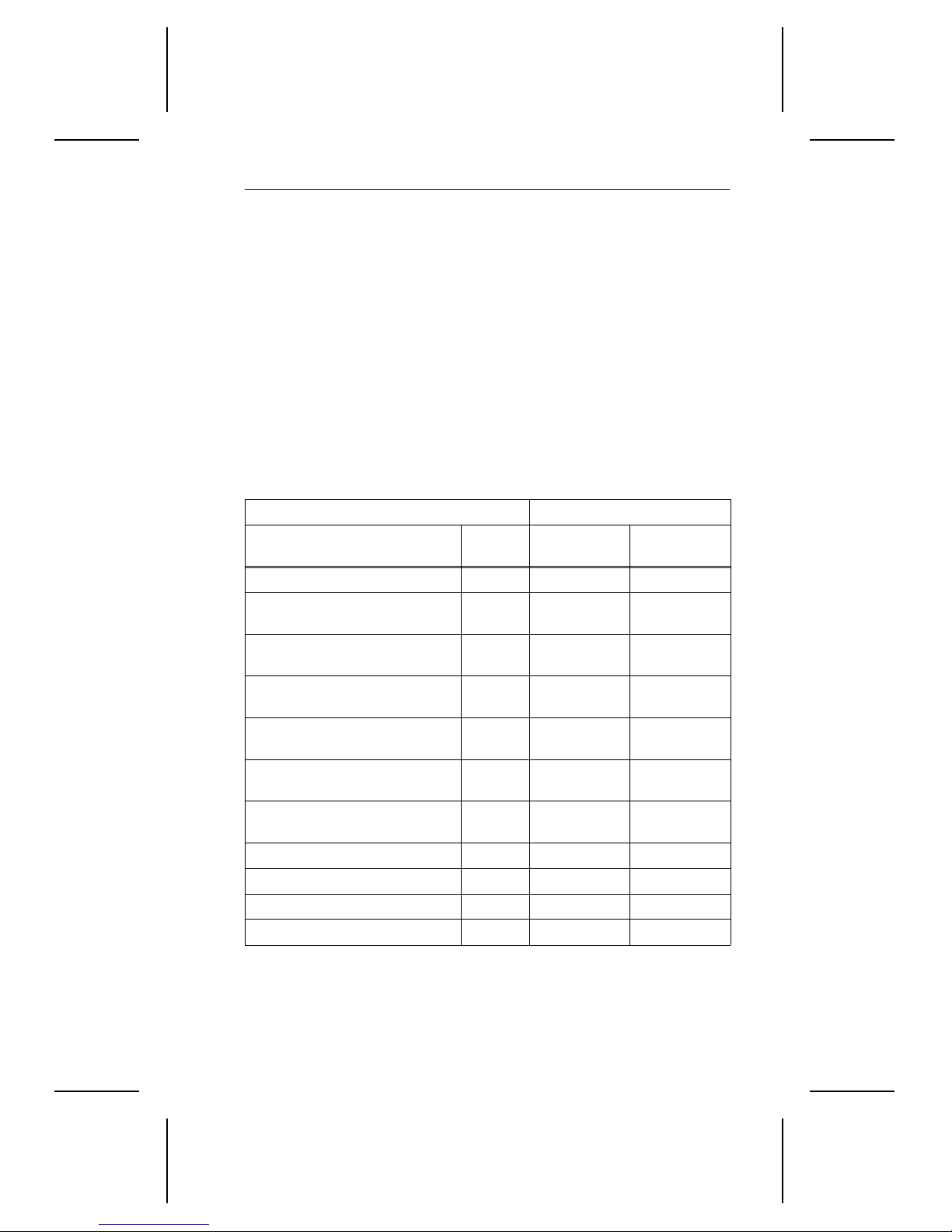
3.2.2 Set Features command (EFH)
The Set Features command (command code E FH) allows you to enable
and disable the multisegmented cache and Automatic Reallocation
features and to identify the transfer modes the drive uses. The multisegmented buffer consists of Read Look-ahead and write-immediate and
write-merging features. The table below lists the features the drives
support. The features that are set to default by the factory are indicated
in the Feature column.
To use the command:
Write the Feature value to the Features register.
1.
Write the Set Features command to the command register.
2.
If the value in the Features register is not supported or is invalid,
Note.
the drives post an Aborted Command error.
At power-on or after a hard reset, the feature selections are r estored to
the factory-default values.
The table below shows alterable features that the drives support. Values
that are preset at the factory are indicated as default in the feature
description.
Feature Value Feature
Enable write cache (default)
02
H
03
04
55
82
84
AA
H
H
H
H
H
H
Set transfer mode
Enable Read Automatic Reallocation (default)
Disable read look-ahead cache
Disable write cache
Disable Read Automatic Reallocation
Enable read look-ahead cache (default)
Page 41
Medalist Pro 6450/5040 Product Manual, February 1997 33
3.2.2.1 PIO and DMA Data-Transfer Modes
You can set the multiword DMA mode and identify the PIO data-transfer
mechanism and transfer mode with the Set Features command. To set
the multiword DMA mode:
1.1.Write Set Features command value 03
(Set Data Transfer mode) to
H
the Features register.
Write a transfer types value to the Sector Count register. The upper 5
2.
bits of this value define the type of data transfer, and the lower 3 bits
encode the mode value.
This changes word 63 of the Identify Drive command to the mode you
enter in the Sector Count register.
The following table identifies allowable transfer types values:
Data-Transfer Mechanism Transfer Types value
Mechanism name
Mode
value
Data
Upper 5 bits
Lower 3 bits
PIO Transfer Mode (default) 2 00000 000
PIO Transfer Mode:
Set PIO Mode = 2
PIO Flow Control Transfer
Mode: Set PIO Mode = 0
PIO Flow Control Transfer
Mode: Set PIO Mode = 1
PIO Flow Control Transfer
Mode: Set PIO Mode = 2
PIO Flow Control Transfer
Mode: Set PIO Mode = 3
PIO Flow Control Transfer
Mode: Set PIO Mode = 4)
2 00000 001
0 00001 000
1 00001 001
2 00001 010
3 00001 011
4 00001 100
Multiword DMA Mode 0 00100 000
Multiword DMA Mode 1 00100 001
Multiword DMA Mode 2 00100 010
Reserved — 01000
If the drive does not support a commanded mode, it returns a 04
Note.
nnn
aborted command error.
Page 42

34 Medalist Pro 6450/5040 Product Manual, February 1997
3.2.3 Standby timer ti m eo ut pe ri od
The Idle command and Standby command Sector Count registers are
used to activate t he Standby timer. The host can enable the Standby
timer by placing a value in the sector-count register of the Idle command
or Standby command. The value corresponds to a predetermined period
of drive inactivity. The table below lists the values the Seagate drives use
and their corresponding timeout period.
Sector Count Register contents Corresp onding timeout period
0 (0
) Timeout disabled
H
1–12 (1
) value = 60 seconds
H–CH
13–240 (DH–F0H) (value * 5) seconds
241–251 (F1
252 (FC
253 (FD
254 (FE
–FBH) (value – 240) * 30) minutes
H
) 21 minutes
H
) 8 hours
H
) Reser ved
H
255 (FFH) 21 minutes 15 seconds
The drives are shipped with the Standby timer disabled.
3.2.4 Sleep command (99H, E6H)
This command performs the same function as the Standby Immedi ate
command (94
, E0H).
H
3.2.5 Automatic Re allocation
This feature allows the drive to identify grown media defects and to
reallocate the sector without host intervention using both Read and Write
Automatic Reallocation.
You can disable Read Reallocation by using the Set Features command
Disable Read Automatic Reallocation, feature value 84
not used for the Read Long command.
. This feature is
H
Page 43
Medalist Pro 6450/5040 Product Manual, February 1997 35
You can disable The Writ e Reallocation, in addition t o write cache by
using the Set Feature command Disable Write Cache, feature value 82
H.
This feature is not implemented for the Write Long command.
You can disable both the Write Reallocation and write cache using value
82
. These two features coexsist as a pair and are enabled/disabled
H
together.
3.2.6 S.M.A.R.T. command (B0H)
Self-Monitoring, Analysis and Reporting Technology (S.M.A.R.T.) is an
emerging technology that provides near-term failure prediction for disc
drives. When S.M.A.R.T. is enabled, the Seagate drive monitors predetermined attributes within its elf that are susceptible to degradation over
time. S.M.A.R.T. makes a status report available s o that the host can
prompt the user to back up the drive if self-monitoring determines that a
failure is likely. Not all failures are predictable. S.M.A.R.T. predictabil ity
is limited to only those attributes the drive can monitor.
The S.M.A.R.T. feature is disabled at the factory. You must have a BIOS,
software driver or application software that supports S.M.A.R.T. to
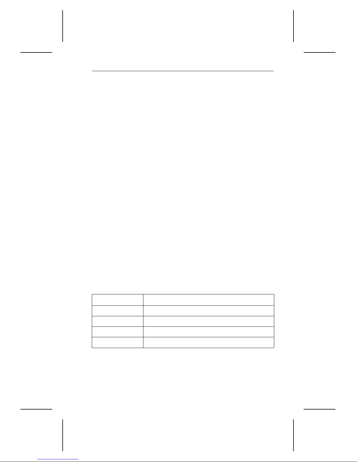
enable this feature. The table below shows the S.M.A.R.T. command
codes the Seagate drives use.
To implement a S.M.A.R.T. command, the host must write the
Note.
value 0x4F to Cylinder_lo register and the value 0xC2 to the
Cylinder_hi register at the same time it writes the S.M.A.R.T.
command code to the Features register. If these values are not
included with the command code, the command is aborted and
0x04 (abort) is written to the Error register.
Command code Feature description
D2
D8
D9
DA
H
H
H
H
Enable/disable attribute autosave
Enable operation
Disable operation
Return S.M.A.R.T. status
Page 44

36 Medalist Pro 6450/5040 Product Manual, February 1997
Page 45
Medalist Pro 6450/5040 Product Manual, February 1997 37
Appendix. Timing diagrams
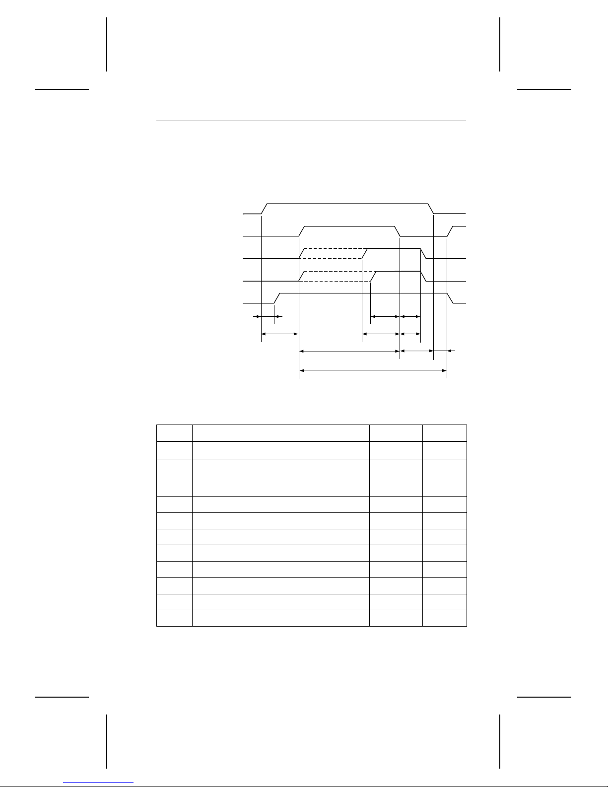
Without IORDY, the drives operate at programmed I/O timing specifications, as shown below.
Address valid
DIOR− and DIOW−
Write data valid
Read data valid
IOCS16−
T7
T1
T2
Figure 8. Programmed I/O timing without IORDY
T0
T3
T5
T6
T4
T9 T8
Time Description M in Max
T0 Cycle time 200 nsec —
Drives address (CS1FX–, CS3FX–,
T1
30 nsec —
DA0, DA1 and DA2) valid and
DIOR– and DIOW setup
T2 DIOW– or DIOR– pulse width 80 nsec —
T3 DIOW– data setup 30 nsec —
T4 DIOW– data hold 15 nsec —
T5 DIOR– data setup 20 nsec
T6 DIOR– data hold 5 nsec —
T7 DIOW– or DIOR– to address valid hold — 40 nsec
T8 DIOW– false to write data hold — 30 nsec
T9 DIOR– false to read data hold 10 nsec
Page 46
38 Medalist Pro 6450/5040 Product Manual, February 1997
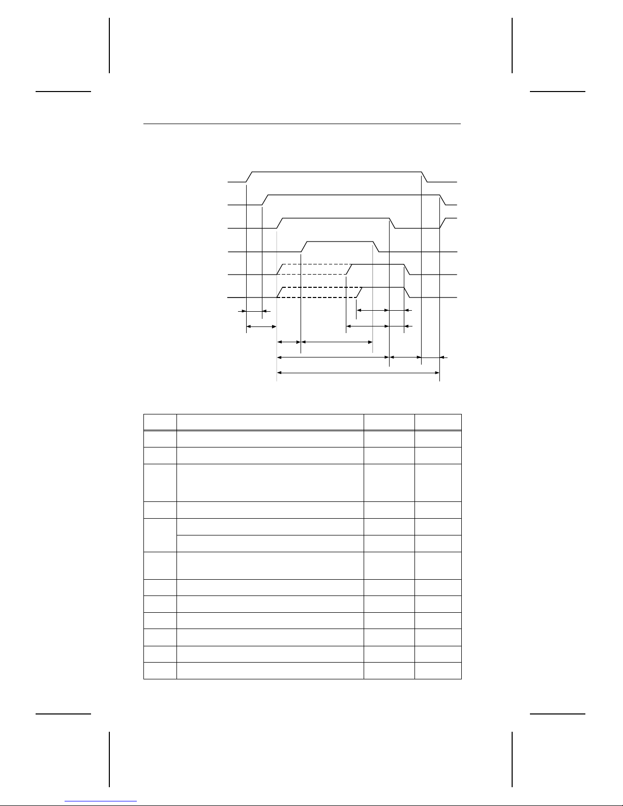
When using IORDY, the drives operate at programmed timing specifications, as shown below.
Address valid
IOCS16−
DIOR− or DIOW−
IORDY
Write data valid
Read data valid
T1
T2
T3
Figure 9. Programmed I/O timing with IORDY
T7
T6
T5
T4
T0
T8
T9
T10
T11
Time Description Min Max
T0 Cycle time 120 nsec —
T1 Address valid until IOCS16– is asserted — 30 nsec
Drive address (CS1FX–, CS3FX–,
T2
25 nsec —
DA0, DA1 and DA2) valid before DIOR–
or DIOW– setup
T3 IORDY s e tu p ti me — —
DIOW– or DIOR– pulse width (8-bit) 70 nsec —
T4
DIOW– or DIOR– pulse width (16-bit) 70 nsec —
T5 IORDY pulse width —
1,250
nsec
T6 DIOW– data setup 20 nsec —
T7 DIOR– data setup 20 nsec —
T8 DIOR– data hold 5 nsec —
T9 DIOW– data hold 10 nsec —
T10 DIOW– or DIOR– to address valid hold 5 nsec —
T11 Address valid until IOCS16– is negated — 25 nsec
Page 47
Medalist Pro 6450/5040 Product Manual, February 1997 39
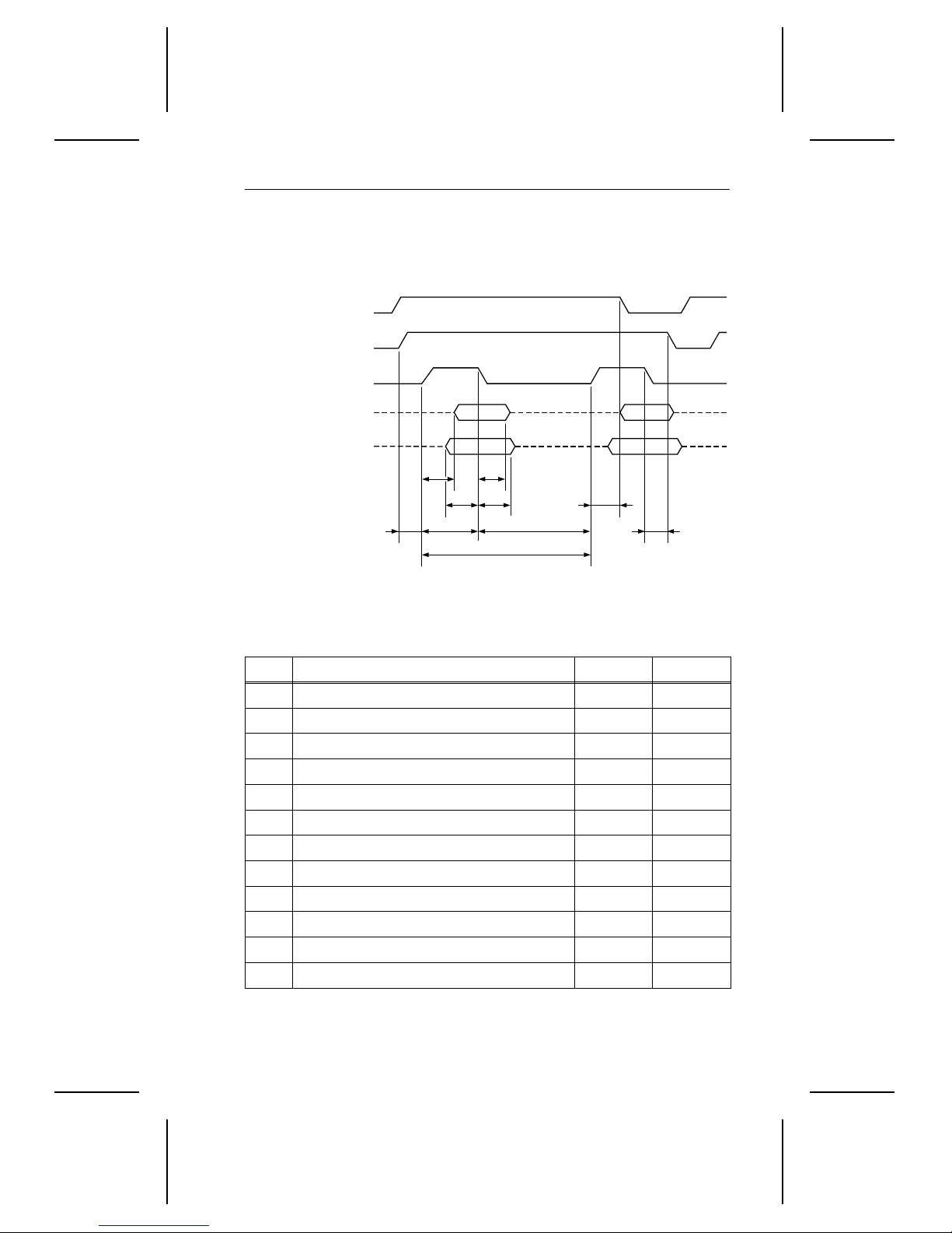
The drives operate at multiword DMA mode 2 timing specifications, as
shown below.
DMARQ
DMACK−
DIOR− or DIOW−
Read data valid
Write data valid
TE
Figure 10. Multiword DMA timing
TF
TG
TH
TDTI TJ
TK
T0
TL
Time Description Min Max
T0 Cycle time 120 nsec —
TD DIOW– or DIOR– pulse width (16-bit) 70 nsec —
TE DIOR– data access — —
TF DIOR– data hold 5 nsec —
TG DIOW– data setup 20 nsec —
TH DIOW– data hold 10 nsec —
TI DMACK– to DIOR– or DIOW– setup 0 nsec —
TJ DIOR– or DIOW– to DMACK– hold 5 nsec —
DIOR– negated pulse width 25 nsec —
TK
R
TK
DIOW– negated pulse width 25 nsec —
W
DIOR– to DMARQ delay — 35 nsec
TL
R
TL
DIOW– to DMARQ delay — 25 nsec
W
Page 48

Page 49

Page 50

Page 51

Page 52
Seagate Technology, Inc.
920 Disc Drive, Scotts Valley, California 95066, USA
Publication Number: 32652-001, February 1997, Printed in USA
 Loading...