

Page 1

. . . . . . . . . . . . . . . . . . . . . . . . .. . . . . . . .
ST3491 Family:
. . . . . . . . . . . . . . . . . . . . . . . . .. . . . . . . . . . .
ST3250A, ST3291A
. . . . . . . . . . . . . . . . . . . . . . . . .. . . . . . . .
ST3391A, ST3491A
. . . . . . . . . . . . . . . . . . . . . . . . .. . . . . . . .
AT Interface Drives
. . . . . . . . . . . . . . . . . . . . . . . . .
Installation Guide
. . . . . . . . . . . . . . . . . . . . . . . . .. . . . . . . .
Page 2

Contents
Read before you begin... . . . . . . . . . . . . . . . . . . . 1
Configuring the drive . . . . . . . . . . . . . . . . . . . . . 2
Attaching cables . . . . . . . . . . . . . . . . . . . . . . . 3
Mounting the drive . . . . . . . . . . . . . . . . . . . . . . 5
Configuring the computer . . . . . . . . . . . . . . . . . . . 5
Low-level formatting . . . . . . . . . . . . . . . . . . . . . 7
Partitioning . . . . . . . . . . . . . . . . . . . . . . . . . . 7
High-level formatting . . . . . . . . . . . . . . . . . . . . . 8
Using the MIRROR utility . . . . . . . . . . . . . . . . . . . 8
Basic troubleshooting . . . . . . . . . . . . . . . . . . . . . 10
Advanced troubleshooting . . . . . . . . . . . . . . . . . . 11
Technical support services . . . . . . . . . . . . . . . . . . 15
Storing and shipping your drive . . . . . . . . . . . . . . . 17
© 1994 Seagate Technology, Inc. All rights reserved
Publication Number: 36255-004, Rev. B
April 1994
®
Seagate
registered trademarks of Seagate Technology, Inc. SeaFAX,
SeaFONE, SeaBOARD and SeaTDD are trademarks of
Seagate Technology, Inc. Other product names are registered
trademarks or trademarks of their owners.
Seagate reserves the right to change, without notice, product
offerings or specifications. No part of this publication may be
reproduced in any form without written permission from Seagate
Technology, Inc.
, Seagate Technology® and the Seagate logo are
Page 3

ST3491 Family Installation Guide, Rev. B 1
Read before you begin...
Application. Your Seagate® drive is designed for IBM AT and
compatible personal computers. It uses the ATA interface.
Warning. Turn off the computer before you open the case, touch
any internal components or install the drive.
Static discharge. Observe these precautions to avoid static
electricity, which can damage a drive or computer. Static electricity can be generated by wool or synthetic clothing, carpets and
plastics of any kind including most bags.
• Keep the drive in its static-shielded bag until you are ready to
install it. Do not attach any cables to the drive while it is in its
static-shielded bag.
• Before you handle the drive, put on a grounded wrist strap, or
ground yourself frequently by touching the metal chassis of a
computer that is plugged into a grounded outlet. Wear a
grounded wrist strap throughout the installation procedure.
• Handle the drive gently and only by its edges or frame. Until
you are ready to install it, place it only on an antistatic surface.
• Do not touch the drive’s connector pins or its printed circuit
board.
Drive handling. The drive is extremely fragile—handle it with
care. Do not attach labels to any part of the drive.
Inspection. After you are familiar with the handling precautions
listed above, inspect the drive. If it appears to be damaged, call
your distributor or dealer immediately.
Warranty. See your authorized Seagate distributor or dealer.
Maintenance and repair. Seagate drives do not require mainte-
nance. The head/disc assembly is sealed; a broken seal voids
the warranty. Seagate customer service centers are the only
facilities authorized to repair Seagate drives. Seagate does not
sanction any third-party repair facilities.
Page 4

2 ST3491 Family Installation Guide, Rev. B
Configuring the drive
1. Turn the computer off.
2. Remove your computer’s cover.
Caution. Special training or tools may be needed to service
laptop computers. Removing the cover may void
your warranty. Review the terms and conditions of
your warranty before removing the cover.
3. Ground yourself. Wear a grounded wrist strap throughout
this procedure, or frequently touch the metal chassis of a
computer that is plugged into a grounded outlet.
4. Remove the drive from its antistatic bag.
5. Install master/slave jumpers. The master/slave jumper
block, shown in Figure 1 on page 4, accepts 2-mm connectors
and jumpers. Use Seagate part number 13211-001 or equivalent.
One-drive system: Configure the drive for a one-drive system
as shown in Figure 1.
Two-drive system: With two ATA interface drives, you must
designate one drive as the master, or drive 0, and the other
drive as the slave, or drive 1. This can be done in either of two
ways:
•
When using a standard ATA interface cable (that is, you are
not using cable select): configure the drive as a master or a
slave using the options jumper block as shown in Figure 1
on page 4.
•
When using cable select (that is, you have a special cable
supporting this drive selection method, and your computer
and both drives all support cable select): first install a jumper
on pins 3-4 of the options jumper block as shown in Figure
1; then use a drive-select cable as described in step 5 of
“Attaching cables” on page 3 to designate master and slave
drives.
Page 5

ST3491 Family Installation Guide, Rev. B 3
Attaching cables
Refer to Figure 1 on page 4 for the locations of the connectors.
1. Make sure the computer is off.
2. Put on a grounded wrist strap.
3. Connect the remote LED (optional).
4. Attach the power cable. Attach one of the computer power
cables from the power supply of your computer to the 4-pin
power connector on the drive.
5. Attach the interface cable. (Interface ribbon cable length
must be 18 inches or less.)
Caution. Connector misalignment can damage the computer
and the drive. Ribbon cables are delicate—be careful not to crimp or strain them.
One-drive system using a standard ATA 40-pin interface cable:
Connect one end of the cable to the computer’s host adapter
card or to the hard drive connector located on the motherboard; connect the other end to the 40-pin interface connector.
Align pin 1 on each cable connector with pin 1 on its matching
equipment connector. (Cable lead 1 going to connector pin 1
is often denoted by a colored edge-stripe on the cable; the
stripe will lie adjacent to the 4-pin power connector.)
Two-drive system with a standard ATA 40-pin interface cable:
If you are using a standard 40-pin two-drive ribbon cable, plug
one connector into J1 on each drive and attach the remaining
connector to the host adapter. Align pin 1 on connectors as
described above for a one-drive system.
Two-drive system using interface cable supporting cable select:
If in step 5 on page 2 you followed the instructions for two
drives and cable-select, you must assign master and slave
status to drives by the following method: to make a drive the
Page 6
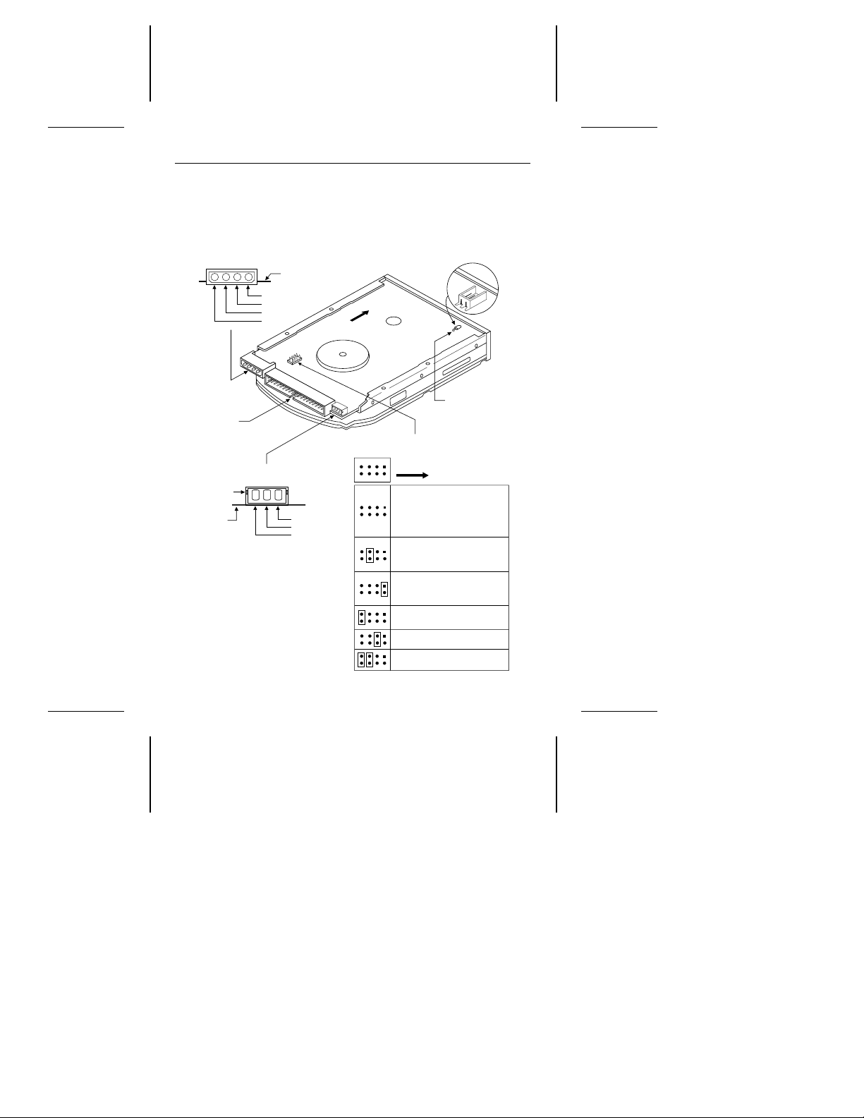
Front
4-pin
power connector
8-pin
options jumper block
Front
Cable select
40-pin
AT interface
connector
4
3
2
1
Circuit board
+5V
+5V return
+12V return
+12V
The drive is a master; a
slave is present, but it does
not have a DASP− signal.
Available
2-pin
header
Drive activity
LED
3-pin
power connector
1
2
3
Keyway
Ground
+12V
+5V
The drive is a master;
a slave is present, but
it is not ATA-compatible.
The drive is a slave to an
ATA-compatible master.
The drive is a master;
the slave is either an
ST3491 family drive or
another ATA-compatible
drive, or there is no slave.
21436
587
Factory test (Do not use.)
Circuit
board
4 ST3491 Family Installation Guide, Rev. B
master, attach it to the connector that has the CSEL signal line
connected to pin 28. To make a drive the slave, attach it to
the connector that has pin 28 unconnected (open). Finally,
Figure 1. Jumpers and connectors
Page 7

ST3491 Family Installation Guide, Rev. B 5
connect the remaining cable connector to the host adapter.
Note that CSEL is grounded on the host adapter.
Mounting the drive
Mount the drive securely in the computer in any orientation using
either the bottom or side mounting holes, as described below.
Position the drive so that you do not strain or crimp the cables.
All ST3491 family drives have the same overall dimensions.
However, the positions of the mounting holes are different for
metric and standard drives.
• Standard size drives have an “S” stamped on the frame runner
and accept 6-32 UNC screws.
• Metric drives have an “M” stamped on the frame runner and
accept M3 screws.
Caution. To prevent drive mounting hole damage, use only the
appropriate type of screws as specified. Tighten them
gently using no more than 6 inch-lb of torque.
Bottom mounting holes. Insert four mounting screws not more
than 0.20 inches (6 full turns) into the drive frame.
Side mounting holes. Insert four mounting screws not more than
0.13 inches (4 full turns) into the drive frame.
After you have mounted the drive in the computer, disconnect
your grounded wrist-strap and replace the computer cover.
Configuring the computer
1. Turn the computer on.
2. Enter the System Setup routine (also known as CMOS Setup)
and define the new drive’s translation geometry as follows:
2A. Select the drive type according to the following guidelines:
Select a drive type matching your drive’s translation geometry.
(continued)
Page 8

6 ST3491 Family Installation Guide, Rev. B
If none of the standard drive types offered by the System
Setup routine match the translation geometry shown in the
following table, select the
type to enter your drive’s translation geometry.
If your System Setup routine does not offer a
drive type, select a standard drive type with a capacity that
approximates, but does not exceed, your drive’s capacity
(shown in the last column of the table). If you do not know
what drive types your System Setup routine supports,
download the FindType utility from the Seagate BBS (see
page 16) to assist you in choosing an appropriate drive
type.
The following table shows the recommended translation geometry for the drive.
user-defined
or
custom
user-defined
drive
Model
ST3250A 213.9 1,024 12 34 204.0
ST3291A 272.7 761 14 50 260.1
ST3391A 341.3 768 14 62 325.5
ST3491A 427.8 899 15 62 408.2
2B. The drive does not use the
parameters. For each parameter, enter the number of
cylinders plus 1. Example for ST3491A: 899+1, or 900.
2C. Save your entered values into CMOS memory, then exit
System Setup. On some systems this is one step.
CHKDSK
Mbytes
Translation geometry
Cyl Heads
write precomp
Sectors
per track
and
CMOS
(Setup)
Mbytes
landing zone
Page 9

ST3491 Family Installation Guide, Rev. B 7
Low-level formatting
AT drives are low-level formatted at the factory to 512 bytes per
sector. You do not need to low-level format AT drives.
Partitioning
You must partition a drive into one or more logical drives before
you can use it. If you are using DOS Version 3.3 or earlier, disc
partitions are limited to about 33 Mbytes. Beginning with DOS
Version 4.0, you can put the entire drive on one partition.
Caution. Partitioning or formatting a drive at any level erases all
data on it. Before you repartition or reformat your drive,
save all existing files to backup files. Seagate assumes
no liability if you erase your data.
You can partition a drive as follows:
1. Put a bootable DOS diskette in the A drive and boot the
computer. This loads DOS from the floppy and runs it.
ENTER
2. At the DOS prompt, type FDISK and then press
the FDISK utility.
3. Select
4. Select
create DOS partition or logical DOS drive
ENTER.
create primary DOS partition
. Use the maximum available size for your primary partition and make the partition
active. This puts the entire drive on one partition and allows
the computer to boot (load DOS) from the partition. Press
ENTER after every selection.
5. After you make all the appropriate selections, the computer
automatically reboots itself.
Many Unix-based operating systems allow you to partition the
drive for DOS applications. See your operating system manual
for details.
to run
and press
Page 10

8 ST3491 Family Installation Guide, Rev. B
High-level formatting
High-level formatting verifies the information written by the lowlevel format and builds the file allocation table (FAT) used by DOS
to access files on the drive. Use the DOS FORMAT utility to
high-level format the drive as follows:
1. Type the following command line at the DOS prompt:
format
drive:
are formatting the boot drive or if your system contains only
one hard drive. To format a non-boot drive, type
/V
formatted. Labeling the drive can prevent someone from accidentally deleting the partition and losing your data.
/S
necessary system files to the drive.
2. When the computer prompts you for a volume label, type any
valid name you want to designate the drive.
In Unix, high-level formatting creates the i-node used for file
access information. Drive formatting and partitioning are both
performed by a single operating system utility. Refer to your Unix
operating system documentation for instructions.
drive:
/V /S
designates the drive you are formatting. Use c: if you
d:
instead.
tells the computer you want to label the drive after it is
tells the computer to make the drive bootable and copy the
Using the MIRROR utility
If a virus or a faulty computer program destroys your drive’s file
allocation table (FAT) or its partition information, you can usually
recover your data if you save copies of these important files. To
do this, add the MIRROR command to your autoexec.bat file.
1.1. Using an ASCII text editor, open the autoexec.bat file, which
is located in the boot drive’s root directory.
2. At the end of the autoexec.bat file, add the following command
line to back up the C: drive’s FAT:
c:\DOS\MIRROR c:
Page 11

ST3491 Family Installation Guide, Rev. B 9
If you have many partitions (logical drives), you can add
additional drive letters (for example, d: e: f:) to the command
line to represent these drives.
Note. If the mirror utility on your computer is not in the DOS
directory under the root directory, you must specify the
pathname leading to the utility’s location.
3. Save your changes, exit the editor and reboot your computer.
After every reboot, the computer automatically executes the
autoexec.bat file. Verify that the MIRROR command runs
successfully; the MIRROR command copies the FAT and
makes a partition record named mirror.fil in the drive’s root
directory. If a virus or a faulty program destroys the FAT,
recovery utilities use this file to recover the FAT.
Now, back up the boot drive’s partition record to a diskette:
1. Insert a blank, formatted diskette in the floppy drive and type
the following command line at the DOS prompt:
c:\DOS\mirror /partn
The computer copies the file mirror.fil to the floppy diskette.
2. Remove the diskette from the drive and keep it in a safe place.
If your drive’s partition record ever becomes corrupted, you
can use recovery utilities along with this diskette to recover
your data. If you ever repartition the drive, back up the partition
record again.
Page 12

10 ST3491 Family Installation Guide, Rev. B
Basic troubleshooting
Note. The Seagate drives in this family include special
power-saving features. If a drive has not been accessed
for a while, it will automatically go into power-saving idle
mode and park the heads. This action may be audible
to the user as a small mechanical sound. However, it is
a normal feature and no cause for concern.
Warning. Always turn off the computer before changing jump-
ers or unplugging cables and cards.
In the event of problems, you should perform the following basic
checks, which can resolve common installation difficulties.
• Verify compatibility. Verify that the host adapter and the
drive are appropriately matched to each other and to your
computer. Refer to relevant documentation for details.
• Verify equipment configuration. Using the instructions in
the drive and host adapter installation guides, make sure that
all appropriate jumpers are installed, or removed, to suit your
application.
• Check the power supply specifications. If new devices are
installed, your computer’s power supply may not support the
new total power requirement. When in doubt, consult your
dealer.
• Check all cards. Verify that all cards are seated in their slots
on the motherboard and are secured with mounting screws.
• Verify the drive type setting stored in system CMOS
memory. The drive type stored in CMOS memory by your
System Setup program must approximate, but not exceed, the
physical specifications of your drive.
• Check all cables. Make sure all ribbon cables and power
cables are securely connected. Ribbon cables are especially
fragile. Verify that they are not crimped or damaged, and if in
doubt, substitute cables that are new or known to be good.
Verify for each cable that cable connector pin 1 aligns with
Page 13

ST3491 Family Installation Guide, Rev. B 11
equipment-connector pin 1. Pin 1 is often denoted by a colored
stripe on one edge of the ribbon cable.
Caution. Do not reverse-plug connectors. This can damage
the computer and the drive.
Note. A floppy diskette cable contains a split and twisted
section and cannot be used with a hard drive.
• Check for viruses.
in your system for the first time, scan the diskette for viruses.
Before you use someone else’s diskette
Advanced troubleshooting
If you have performed the preceding basic checks but the problem has not been solved, follow these guidelines for troubleshooting specific cases:
The system does not recognize the presence of the drive.
• Check all cables.
• Make sure the power supply is adequate for system needs.
• Reboot the computer and make sure the drive motor runs. (If
your drive is very quiet, it may be difficult to hear its discs reach
operating speed.) If the drive does not appear to be running,
recheck all drive cables.
• Verify the CMOS setup drive type values.
• Try a warm boot (a reboot without turning off computer power).
To do this, press CTRL, ALT, and DELETE at the same time.
If a warm boot causes a previously unrecognized drive to
become recognized, there may be a timing problem in which
the drive fails to become ready for operation before the computer’s power-on self-test is complete.
One possible solution is to slow your computer’s processor
speed during startup. If your computer has a turbo switch, set
it to slow speed before turning the computer on. If there is no
turbo switch, you may be able to use keyboard commands to
slow the processor speed; see your computer manual for
Page 14

12 ST3491 Family Installation Guide, Rev. B
details. After the computer is up and running, return the
processor to the fast speed. Another solution is to warm-boot
your computer after every power-on.
• Check for I/O address conflicts. To isolate the conflict, first
verify that the drive and host adapter are compatible with your
computer by removing all the peripheral adapter cards (power
must be off) except for the video card. Then reinstall the drive
and host adapter card. If this is successful, reinstall the other
peripherals one at a time until the conflict reoccurs.
After you have isolated the source of the address conflicts,
you can resolve the conflict by changing the I/O address of the
peripheral that appears to cause the conflict.
The dealer partitioned and high-level formatted the drive for
you in the store. Later, you installed the drive and it does not
work at all.
• Reboot the computer and make sure the drive spins up.
• Check all cables.
• Make sure the power supply is adequate for system needs.
• Use the same version of DOS within all partitions. Make sure
the DOS version the dealer used to partition and high-level
format the drive is the same as the version you have installed
on your computer. If it isn’t, see your dealer.
• Verify the CMOS drive type setup value. You must install the
drive using the same drive type or translation geometry that
was set before initial partitioning by your computer dealer.
• Check for I/O address conflicts between peripheral cards.
• Check for viruses.
The screen goes blank when you power up the system.
• Make sure the monitor is plugged in and turned on.
• Check all cards. Make sure the video card is seated in its slot
and secured with mounting screws.
Page 15

ST3491 Family Installation Guide, Rev. B 13
• Check all cables. Make sure the video card cables are securely attached.
• While the computer is powered down, remove the drive host
adapter. If the screen turns on after you reboot, the host
adapter may be incompatible or defective. If so, see your
dealer.
The system hangs in FDISK or fails to create or save the
partition record.
• Check all cables.
• The DOS utilities diskette may be corrupted. Try your backup
DOS diskette.
• Make the partitions smaller.
• Use another drive type or translation geometry. Sometimes
the computer’s BIOS does not accept a particular translation
geometry for writing into the CMOS setup memory.
• Change the interrupt jumper setting on the host adapter.
• Check for media defects at the beginning of the drive. Use a
third-party surface scan utility.
System error message, “Drive not Ready,” appears.
• Check all cables. For each ribbon cable, verify that pin 1 of the
cable is matched to pin 1 of the connector. Pin 1 is usually
denoted by a stripe on the side of the ribbon cable.
• Make sure the power supply is adequate for system needs.
• Reboot the computer and make sure the drive spins up.
The FDISK error message, “No Fixed Disk Present,” appears.
• Check all cables.
• Make sure the power supply is adequate for system needs.
• Reboot the computer and make sure the drive spins up.
• Verify the CMOS setup drive type values.
• Check for I/O address conflicts.
Page 16

14 ST3491 Family Installation Guide, Rev. B
During the DOS high-level format, the drive does not format
to full capacity.
• Verify your computer’s CMOS setup drive type values. One of
the following problems may have occurred: 1) CMOS setup
may be set for an incorrect drive type or translation geometry;
2) you may have entered a parameter value that exceeded the
physical capacity of the drive; or 3) you selected a CMOS
geometry or drive type that does not take full advantage of the
drive’s capacity.
If any of these cases is true, follow the instructions on pages
5 and 6 for configuring the computer.
If you reset CMOS setup drive type value, partition and highlevel format the drive again. Note that DOS does not allow
more than 1,024 cylinders.
• If you partitioned the drive into individual logical drives, you
may need to make the partitions smaller so that the computer
can use all of the drive’s capacity.
DOS messages, “Disk Boot Failure,” “Non-System Disk,” or
“No ROM Basic - SYSTEM HALTED,” appear.
• Check all cables.
• Use the same version of DOS throughout all partitions on your
computer.
• Reinstall the DOS system files using the DOS SYS utility.
• Verify using FDISK that the primary partition is active.
• Check for viruses.
Page 17

ST3491 Family Installation Guide, Rev. B 15
Technical support services
Always consult your computer dealer first for technical support.
Dealers can offer help with unique system configurations.
Technical support is available for all Seagate products by calling
the SeaFAX, Seagate Technical Support FAX, SeaFONE,
SeaBOARD and SeaTDD services.
SeaFAX.
You can use a touch-tone telephone to access Seagate’s
automated FAX system to receive technical support information by return FAX. This service is available 24 hours daily.
Location
United States
England
Telephone number
408-438-2620
44-62-847-7080
Seagate Technical Support FAX. 408/438-8137
You can FAX questions or comments to technical support
specialists 24 hours daily. Responses are sent between
A.M. and 5:00 P.M. (Pacific time), Monday through Friday.
8:00
SeaFONE. 408/438-8222
You can talk to a technical support specialist between
A.M. and 5:00 P.M. (Pacific time), Monday through Friday.
8:00
SeaFONE provides recorded technical information on selected Seagate products while you are on hold. You can
access the recordings 24 hours daily. Before calling, note your
system configuration and drive model number (ST
xxxx
).
Page 18

16 ST3491 Family Installation Guide, Rev. B
SeaBOARD
Using a modem, you can:
• Access documentation, drive specifications and jumper set-
tings for Seagate’s entire product line.
• Download software for installing and analyzing your drive.
• Request a return phone call from the technical support staff.
SeaBOARD is available 24 hours daily. It supports communications up to 9,600 baud. Set your communications software
to eight data bits, no parity, and one stop bit (8-N-1). SeaBOARD phone numbers are listed in the following table.
Location Modem number
United States 408-438-8771
Canada 416-856-5581
England 44-62-847-8011
France 33-1-40 67 10 34
Germany 49-89-140-9331
Singapore 65-292-6973
Australia 61-2-756-2359
Korea 82-2-556-7294
SeaTDD. 408/438-5382
Using a telecommunications device for the deaf (TDD), you
can send questions or comments 24 hours daily and exchange
messages with a technical support specialist between 8:00
A.M.
and 5:00
P.M.
(Pacific time), Monday through Friday
.
Page 19

Foam
Antistatic bag
Drive
Foam
Foam
Antistatic bag
Drive
Foam
ST3491 Family Installation Guide, Rev. B 17
Storing and shipping your drive
Keep your original box and packing materials for storing or
shipping your drive. The box has a
label. Shipping a drive in an unapproved container voids the
warranty. Call your authorized Seagate distributor to purchase
additional boxes.
The following figure shows how a drive fits in an approved
single-pack box, including the packing materials.
Seagate Approved Package
Figure 2. A drive in an approved package
Page 20

Seagate Technology, Inc.
920 Disc Drive, Scotts Valley, CA 95066, USA
Publication Number: 36255-004, Rev. B Printed in USA
 Loading...