

Page 1

.
.........................................
.
.
.
.
.
.
Barracuda ATA V Family
.........................................
ST3120023A, ST380023A,
.........................................
ST360015A, ST340017A,
.........................................
ST330013A
.........................................
Ultra ATA Interface Drives
.........................................
Product Manual
.........................................
Page 2

Page 3

.......................................
Barracuda ATA V Family
.......................................
ST3120023A, ST380023A,
.......................................
ST360015A, ST340017A,
.......................................
ST330013A
.......................................
Ultra ATA Interface Drives
.......................................
Product Manual
.......................................
Page 4

©2002 Seagate Technology LLC All rights reserved
Publication number: 1002 2137 4, R ev. E
December 2002
Seagate, Seagate Technology, and the Seagate logo are either registered
trademarks or trademarks of Seagate Technology LLC. Barracuda,
DiscWizard, SeaFAX, SeaFONE, SeaShell , SeaShield, S eaTDD, and 3D
Defense System are either registered trademarks or trademarks of
Seagate Technology LLC. Other product names are registered trademarks or trademarks of their owners.
Seagate reserves the ri ght to change, without notic e, product offerings or
specifications. No par t of this publication may be reprodu ced in any form
without written permission of Seagate Technology LLC.
Page 5

Revision status summary sheet
Revision Date Writer/PLM Sheets Affected
Rev. A 09/16/02 L. Newman/J. Singh All.
Rev. B 09/18/02 L. Newman/J. Singh Pages 3 and 7.
Rev. C 09/19/02 L. Newman/J. Singh Pages 3 and 6.
Rev. D 10/14/02 L. Newman/J. Singh Pages 5, 8, 10, 27,
30, and 33.
Rev. E 12/11/02 L. Newman/J. Singh Page 16.
Page 6

Page 7

Barracuda ATA V Product Manual, Rev. E v
Contents
1.0 Introduction. . . . . . . . . . . . . . . ...........................1
2.0 Drivespecifications...................................3
2.1 Specification summary table . . . . . . . . . . . . . . . . . . . . . . . 3
2.2 Formatted capacity . . . . . . . . . . . . . . . . . . . . . . . . . . . . . . 6
2.3 Default logical geometry . . . . . . . . . . . . . . . . . . . . . . . . . . 6
2.4 Physical organization. . . . . . . . . . . . . . . . . . . . . . . . . . . . . 6
2.5 Recording and interface technology . . . . . . . . . . . . . . . . . 7
2.6 Physical characteristics . . . . . . . . . . . . . . . . . . . . . . . . . . . 7
2.7 Seek time. . . . . . . . . . . . . . . . . . . . . . . . . . . . . . . . . . . . . . 8
2.8 Start/stop times . . . . . . . . . . . . . . . . . . . . . . . . . . . . . . . . . 8
2.9 Power specifications . . . . . . . . . . . . . . . . . . . . . . . . . . . . . 8
2.9.1 Power consumption . . . . . . . . . . . . . . . . . . . . . . 9
2.9.2 Conducted noise . . . . . . . . . . . . . . . . . . . . . . . 12
2.9.3 Voltage tolerance . . . . . . . . . . . . . . . . . . . . . . . 12
2.9.4 Power-management modes. . . . . . . . . . . . . . . 12
2.10 Environmental specifications . . . . . . . . . . . . . . . . . . . . . . 13
2.10.1 Ambient temperature . . . . . . . . . . . . . . . . . . . . 13
2.10.2 Temperature gradient. . . . . . . . . . . . . . . . . . . . 14
2.10.3 Humidity . . . . . . . . . . . . . . . . . . . . . . . . . . . . . . 14
2.10.4 Altitude . . . . . . . . . . . . . . . . . . . . . . . . . . . . . . . 14
2.10.5 Shock . . . . . . . . . . . . . . . . . . . . . . . . . . . . . . . . 15
2.10.6 Vibration . . . . . . . . . . . . . . . . . . . . . . . . . . . . . . 15
2.11 Acoustics . . . . . . . . . . . . . . . . . . . . . . . . . . . . . . . . . . . . . 16
2.12 Electromagnetic immunity . . . . . . . . . . . . . . . . . . . . . . . . 17
2.13 Reliability . . . . . . . . . . . . . . . . . . . . . . . . . . . . . . . . . . . . . 17
2.14 Agency certification . . . . . . . . . . . . . . . . . . . . . . . . . . . . . 18
2.14.1 Safety certification . . . . . . . . . . . . . . . . . . . . . . 18
2.14.2 Electromagnetic compatibility. . . . . . . . . . . . . . 18
2.14.3 FCC verification . . . . . . . . . . . . . . . . . . . . . . . . 19
3.0 Configuring and mounting the drive. . . . . . . . .............21
3.1 Handling and static discharge precautions . . . . . . . . . . . 21
3.2 Jumper settings . . . . . . . . . . . . . . . . . . . . . . . . . . . . . . . . 22
3.2.1 Master/slave configuration . . . . . . . . . . . . . . . . 22
3.2.2 Cable-select option. . . . . . . . . . . . . . . . . . . . . . 22
3.2.3 Alternate capacity jumper. . . . . . . . . . . . . . . . . 23
3.2.4 Ultra ATA/100 cable . . . . . . . . . . . . . . . . . . . . . 23
3.3 Drive mounting. . . . . . . . . . . . . . . . . . . . . . . . . . . . . . . . . 24
4.0 ATAinterface .......................................25
4.1 ATA interface signals and connector pins . . . . . . . . . . . . 25
Page 8

vi Barracuda ATA V Product Manual, Rev. E
4.1.1 Supported ATA commands. . . . . . . . . . . . . . . . 27
4.1.2 Identify Device command . . . . . . . . . . . . . . . . .28
4.1.3 Set Features command. . . . . . . . . . . . . . . . . . .33
4.1.4 S.M.A.R.T. commands . . . . . . . . . . . . . . . . . . .35
5.0 Seagate Technology support services . . . . . . . ............37
Page 9

Barracuda ATA V Product Manual, Rev. E vii
List of Figures
Figure 1. Typical 5V startup and operation current profile . . . . . . . . . 11
Figure 2. Typical 12V startup and operation current profile . . . . . . . . 11
Figure 3. Master/slave jumper settings . . . . . . . . . . . . . . . . . . . . . . . 22
Figure 4. Ultra ATA cable connectors . . . . . . . . . . . . . . . . . . . . . . . . 23
Figure 5. Mounting dimensions—top, side and end view. . . . . . . . . . 24
Figure 6. I/O pins and supported ATA signals . . . . . . . . . . . . . . . . . . 26
Page 10

viii Barracuda ATA V Product Manual, Rev. E
Page 11

Barracuda ATA V Product Manual, Rev. E 1
1.0 Introduction
This manual describes the functional, mechanical and interface specifications
for Seagate
®
Barracuda® ATA V ST3120023A, ST380023A, ST360015A,
ST340017A, and ST330013A model drives. These drives provide the following
key features:
• 7,200-RPM spindle speed and 2-Mbyte buffer combine for superior desktop
performance.
• High instantaneous (burst) data transfer rates (up to 100 Mbytes per second)
using Ultra DMA mode 5.
• Giant magnetoresistive (GMR) recording heads and EPRML technology,
which provide the drives with increased areal density.
• State-of-the-art cache and on-the-fly error-correction algorithms.
• Full-track multiple-sector transfer capability without local processor interven-
tion.
• Quiet operation.
• 350 Gs nonoperating shock.
®
• The innovative, shock-absorbing SeaShield
cover protects the drive against
electrostatic dischar ge (ESD) and ot her handling da mage. It also i ncludes
installation instructions and jumper settings.
• SeaTools diagnostic software performs a drive self-test that eliminates
unnecessary drive returns.
• The 3D Defense System™, which in cludes Drive Defens e, Data Defense,
and Diagnostic Defense, offers the indu stry’s mos t comprehen sive protec tion for disc drives.
• Support for S.M.A.R.T. drive monitoring and reporting.
• Support for Read Multiple and Write Multiple commands.
• Support for autodetection of master/slave drives that use cable select
(CSEL).
Page 12

2 Barracuda ATA V Product Manual, Rev. E
Page 13
Barracuda ATA V Product Manual, Rev. E 3
2.0 Drive specifications
Unless otherwise noted, all specific ations are me asured un der ambient c onditions, at 25°C, and nom inal po wer. For conveni ence, th e phrases the drive
and this drive are used throughout this manual to indicate ST3120023A,
ST380023A, ST360015A, ST340017A and ST330013A model drives.
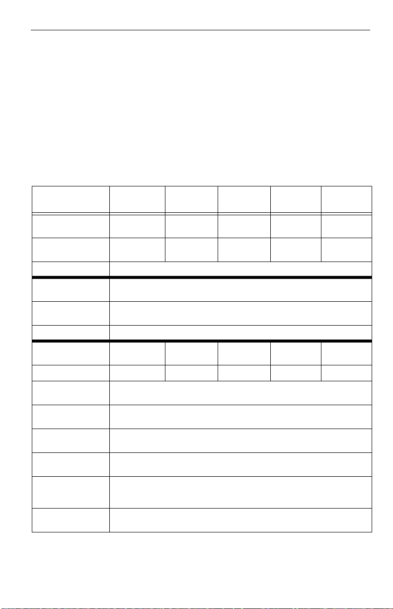
2.1 Specification summary table
The specification s listed in this table are for quick referenc e. For details on
specification me asurement or definition, see the appropriate section of this
manual.
Drive
specification
Formatted Gbytes
(512 bytes/sector)
Guaranteed
sectors
Bytes per sector 512
Default sectors
per track
Default read/write
heads
Default cylinders 16,383
Physical read/write
heads
Discs 2 2 1 1 1
Recording density
BPI (bits/inch max)
Track density TPI
(tracks/inch max)
Areal density
(Mbits/inch
Spindle speed
(RPM)
Max. Internal
transfer rate
(Mbits/sec)
Sustained transfer
rate (Mbytes/sec)
2
max)
ST3120023A ST380023A ST360015A ST340017A ST330013A
120 80 60 40 30
234,441,648 156,301,488 117,231,408 78,165,360 58,633,344
63
16
43221
542,000
78,000
42,200
7,200
570
27 to 44
Page 14

4 Barracuda ATA V Product Manual, Rev. E
Drive
specification
I/O data transfer
rate (Mbytes/sec
max)
ATA data-transfer
modes supported
Cache buffer 2 Mbytes (2,048 kbytes)
Height (mm max) 26.1
Width (mm max) 101.85
Length (mm max) 147.0
Weight (typical) 635 grams (1.4 lb)
Average latency
(msec)
Power-on to ready
(sec typical)
Standby to ready
(sec typical)
Startup current
(typical) 12V (peak)
Track-to-track seek
time (msec typical)
Average seek time
(msec typical)
Average seek, read
(msec typical)
Average seek, write
(msec typical)
Seek power
typical)
Read/write power
(typical)
Idle mode (typical) 9.5 watts
Standby mode 0.7 watts (typical), 0.75 watts (max)
Sleep mode 0.7 watts (typical), 0.75 watts (max)
Voltage tolerance
(including noise)
ST3120023A ST380023A ST360015A ST340017A ST330013A
100
PIO modes 0–4
Multiword DMA modes 0–2
Ultra DMA modes 0–5
4.16
10 sec
10 sec
2.8 amps
1.0 (read), 1.2 (write)
9.4 9.0
9.4 9.0
10.5 10.0
13 watts
12 watts
5V ± 5%
12V ± 10%
Page 15

Barracuda ATA V Product Manual, Rev. E 5
Drive
specification
Ambient
temperature
Temperature
gradient
(°C per hour max)
Relative humidity 5% to 90% (operating)
Relative humidity
gradient
Wet bulb temperature (°C max)
Altitude,
operating
Altitude,
nonoperating
(below mean sea
level, max)
Shock, operating
(Gs max at 2 msec)
Shock,
nonoperating
(Gs max at 2 msec)
Vibration,
operating
Vibration,
nonoperating
Drive acoustics
Sound power (bels)
Quiet seek
Performance seek
Nonrecoverable
read errors
Mean time between
failures (power-on
hours)
Contact start-stop
cycles (25°C, 40%
relative humidity)
SeaShield Yes
ST3120023A ST380023A ST360015A ST340017A ST330013A
0° to 60°C (operating)
–40° to 70°C (nonoperating)
20°C (operating)
30°C (nonoperating)
5% to 95% (nonoperating)
30% per hour max
30 (operating)
40 (nonoperating)
–198.12 m to 3,048 m
(–650 ft to 10,000+ ft)
Idle*
–198.12 m to 12,192 m
(–650 ft to 40,000
350 Gs
0.50 Gs (0 to peak, 22–350 Hz)
5.0 Gs (0 to peak, 22–350 Hz)
(two discs) (one disc)
2.8 (typical), 3.0 (max)
2.8 (typical), 3.0 (max)
3.3 (typical), 3.6 (max)
1 per 10
600,000
50,000
+ ft)
63
2.1 (typical), <2.5 (max)
2.4 (typical), 2.8 (max)
3.0 (typical), 3.4 (max)
14
bits read
*During periods of drive idle, some offline activity may occur according to the S.M.A.R.T.
specification, which may increase acoustic and power to operational levels.
Page 16
6 Barracuda ATA V Product Manual, Rev. E
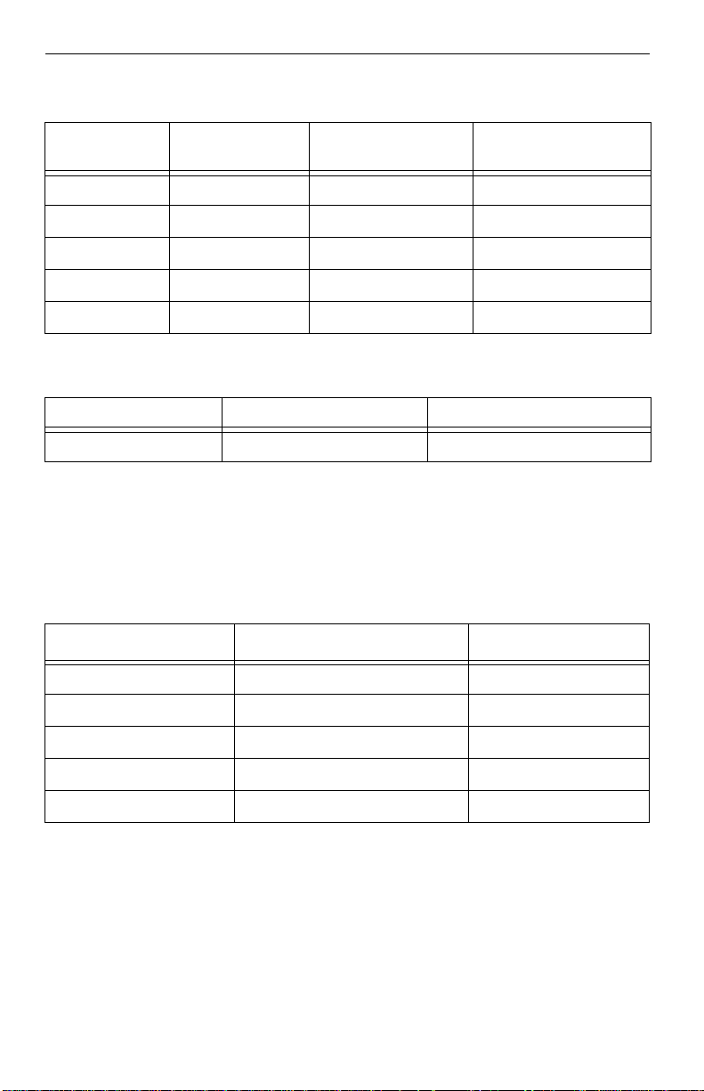
2.2 Formatted capacity
Model
ST3120023A 120 Gbytes 23 4,4 41,648 512
ST380023A 80 Gbytes 156,301,488 512
ST360015A 60 Gbytes 117,231,408 512
ST340017A 40 Gbytes 78,165,360 512
ST330013A 30 Gbytes 58,633,344 512
capacity
Formatted
Guaranteed
sectors Bytes per sector
2.3 Default logical geometry
Cylinders Read/write heads Sectors per track
16,383 16 63
LBA mode
When addressing these dri v es in LB A mo de, al l bl oc ks (s ector s ) are con secutively numbered from 0 to n–1, where n is the number of guaranteed sectors
as defined above.
2.4 Physical organization
Model Read/write heads Number of discs
ST3120023A 4 2
ST380023A 3 2
ST360015A 2 1
ST340017A 2 1
ST330013A 1 1
Page 17
Barracuda ATA V Product Manual, Rev. E 7
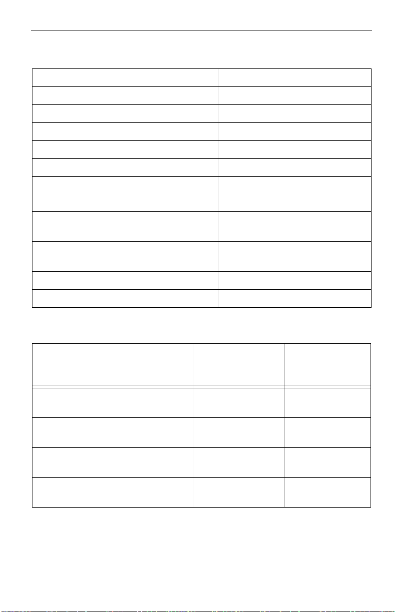
2.5 Recording and interface technology
Interface ATA
Recording method 16/17 EPRML
Recording density BPI (bits/inch max) 542,000
Track density TPI (tracks/inch max) 78,000
Areal density (Mbits/inch
Spindle speed (RPM) (± 0.2%) 7,200
Max. Internal transfer rate (Mbits/sec) 570
2
max) 42,200
Sustained transf e r rate
(Mbytes/sec)
I/O data transfer rate
(Mbytes/se c ma x)
Interleave 1:1
Cache buffer 2 Mbytes (2,048 kbytes)
27 to 44
16.6 (PIO mode 4)
100 (Ultra DMA mode 5)
2.6 Physical characteristics
ST360015A
Drive specification
Maximum height (mm)
(inches)
Maximum width (mm)
(inches)
Maximum length (mm)
(inches)
Typical weight (grams)
(pounds)
ST3120023A
ST380023A
26.1
1.028
101.85
4.01
147.0
5.787
635
1.40
ST340017A
ST330013A
26.1
1.028
101.85
4.01
147.0
5.787
635
1.40
Page 18
8 Barracuda ATA V Product Manual, Rev. E
2.7 Seek time
Seek measurements a re taken with nom inal p ower at 25°C amb ient tem perature. All times are measured using drive diagnostics. The specifications in
the table below are defined as follows:
• Track-to-track seek time is an avera ge of all possibl e single-tr ack seeks in
both directions.
• Average seek time is a true statistical random average of at leas t 5,000
measurements of seeks between random tracks, less overhead.
Typical seek times (msec) Read Write
Track-to-track 1.0 1.2
Average
2 discs
1 disc
Average latency: 4.16 4.16
9.4
9.0
10.5
10.0
Note. These drives are designed to consistently meet the seek times represented
in this manual. Physical seeks, regardless of mode (such as track-to-track
and average), are expected to meet the noted values. However, due to the
manner in which these drives are formatted, benchmark tests that include
command overhead or measure logical seeks may produce results that vary
from these specifications.
2.8 Start/stop times
Power-on to Ready (sec) 10 (max)
Standby to Ready (sec) 10 (max)
Ready to spindle stop (sec) 10 (max)
2.9 Power specifications
The drive receives DC power (+5V or +12V) through a four-pin standard drive
power connector.
Page 19

Barracuda ATA V Product Manual, Rev. E 9
2.9.1 Power consumption
Power requirements for the dr ives are liste d in the table on page 10. Typical
power measurements are based on an average of drives tested, under nominal
conditions, using 5.0V and 12.0V input voltage at 25°C ambient temperature.
• Spinup power
Spinup power is measured fr om the time of power-on to the time that th e
drive spindle reaches operating speed.
• Seek mode
During seek mode, the read/write actuator arm moves towar d a specific
position on the disc surface and does not execute a read or write operation.
Servo electronics are ac tive. Seek m ode po wer r eprese nts th e worst-c ase
power consumption, using only random seeks with read or write latency time.
This mode is not typical and is provided for worst-case information.
• Read/write power and current
Read/write power is measured with the heads on track, based on a 16-sector
write followed by a 32-msec delay, then a 16-sector read followed by a 32msec delay.
• Operating power and current
Operating power is measured using 40 percen t random seeks , 40 percent
read/write mode (1 write for each 10 reads) and 20 percent drive idle mode.
• Idle mode power
Idle mode power is measured with the drive up to speed, with servo
electronics active and with the heads in a random track location.
• Standby mode
During Standby mode, the drive accepts commands, but the drive is not
spinning, and the servo and read/write electronics are in power-down mode.
Page 20

10 Barracuda ATA V Product Manual, Rev. E
Power dissipation
(watts, ST3120023A, 2-disc)
Average
(watts, 25° C)
5V typ
amps
12V typ
amps
Spinup — — 2.8 (peak)
Idle 7.5 0.525 0.407
Idle* (with offline activity) 9.5 0.844 0.439
Operating 40% r/w.
40% seek, 20% inop.
12 0.634 0.74
Seeking 13 0.511 0.871
Standby 0.7 0.116 0.01
Sleep 0.7 0.116 0.01
*During periods of drive idle, some offline activity may occur according to the S.M.A.R.T.
specification, which may increase acoustic and power to operational levels.
Page 21

Barracuda ATA V Product Manual, Rev. E 11
2.9.1.1 Typical current profile
0.9
DC average of waveform
0.75
0.6
Amps
0.45
0.3
0.15
+5 Volt Current during spindle start — Typical Amperes
0.0
0.0 2 4 6 8 10 12 14 16
Seconds
Figure 1. Typical 5V startup and operation current profile
2.25
+12 Volt Current during spindle start — Typical Amperes
1.875
1.5
Amps
1.125
0.75
0.375
0.0
0.0 2 4 6 8 10 12 14 16
Seconds
DC average of waveform
Figure 2. Typical 12V startup and operation current profile
Page 22

12 Barracuda ATA V Product Manual, Rev. E
2.9.2 Conducted noise
Input noise ripple is measured at the host system power supply across an
equivalent 80-ohm resistive load on the +12 volt line or an equivalent 15-ohm
resistive load on the +5 volt line.
• Using 12-volt power, the drive is expected to operate with a maximum of 120
mV peak-to-peak square-wave injected noise at up to 10 MHz.
• Using 5-volt power, the drive is expected to operate with a maximum of 100
mV peak-to-peak square-wave injected noise at up to 10 MHz.
Note. Equival ent r esistan ce is cal culated b y div idin g the n ominal volt age by
the typical RMS read/write current.
2.9.3 Voltage tolerance
Voltage tolerance (including noise):
5V ± 5%
12V ± 10%
2.9.4 Power-management modes
The drive provides programmable power management to provide greater
energy efficiency. In most systems, you can control power management
through the system setu p program. The drive featur es the following powermanagement modes:
Power modes Heads Spindle Buffer
Active Tracking Rotating Enabled
Idle Tracking R otating Enabled
Standby Parked Stopped Enabled
Sleep Parked Stopped Disabled
• Active mode
The drive is in Active mode during the read/write and seek operations.
• Idle mode
The buffer remains enabled, and the drive accepts all commands and returns
to Active mode any time disc access is necessary.
• Standby mode
The drive enters Standby mode when the host sends a Standby Immediate
Page 23

Barracuda ATA V Product Manual, Rev. E 13
command. If the host has s et the standby timer, the drive can als o enter
Standby mode automat ically after the driv e has bee n inacti ve for a specifiable length of time. The standby timer delay is established using a Standby
or Idle command. In Standb y mode, the drive buffer is enable d, the heads
are parked and the sp indle is at rest. The drive accepts all c om m an ds an d
returns to Active mode any time disc access is necessary.
• Sleep mode
The drive enters Sleep mode after receiving a Sleep command from the
host. In Sleep mode, the drive buffer is disabled, the heads are parked and
the spindle is a t r es t. Th e dr i ve le av es Sl eep mode after it recei ves a H a rd
Reset or Soft Reset from the host. After receiving a reset, the dr ive exits
Sleep mode and enters Standby mode with all current translation parameters
intact.
• Idle and Standby timers
Each time the drive performs an Active function (read, write or s eek), the
standby timer is reinitialized and be gins counting down from its specified
delay times to zero. If the standby timer reaches zero before any drive activity
is required, the d riv e m ake s a transition to Standby mode. In both Idle and
Standby mode, the drive accepts all commands and returns to Active mode
when disc access is necessary.
2.10 Environmental specifications
2.10.1 Ambient temperature
Ambient temperature is defined as the temperature of the environment immediately surrounding the drive. Actual drive case temperature should not exceed
69°C (156°F) within the operating ambient conditions.
Above 1,000 feet (305 meters), the maximum temperature is derated linearly
to 112°F (44°C) at 10,000 feet (3,048 meters).
Operating: 0° to 60°C (32° to 140°F)
Nonoperating: –40° to 70°C (–40° to 158°F)
Page 24

14 Barracuda ATA V Product Manual, Rev. E
2.10.2 Temperature gradient
Operating: 20°C per hour (68°F per hour max), without
condensation
Nonoperating: 30°C per hour (86°F per hour max)
2.10.3 Humidity
2.10.3.1 Relative humidity
Operating: 5% to 90% noncondensing (30% per hour max)
Nonoperating: 5% to 95% noncondensing (30% per hour max)
2.10.3.2 Wet bulb temperature
Operating: 30°C (86°F max)
Nonoperating: 40.0°C (104°F max)
2.10.4 Altitude
Operating: –198.12 m to 3,048 m (–650 ft to 10,000+ ft)
Nonoperating: –198.12 m to 12,192 m (–650 ft to 40,000+ ft)
Page 25

Barracuda ATA V Product Manual, Rev. E 15
2.10.5 Shock
All shock spec ifications assum e that the driv e is mounted secu rely with the
input shock applied at the drive mounting screws. Shock may be applied in the
X, Y or Z axis.
2.10.5.1 Operating shock
These drives comply wi th the performanc e levels speci fied in this do cument
when subjected to a maxi mum operating sho ck of 63 Gs based on ha lf-sine
shock puls es of 2 ms ec . S ho c ks sh o ul d no t be re p eat ed m or e t h an t wo t im e s
per second.
2.10.5.2 Nonoperating shock
The nonoperating sh oc k l eve l tha t the driv e ca n ex pe ri ence without incurring
physical damage or degr adation in p erformance when subseque ntly put int o
operation is 350 Gs based on a nonrepetitive half-sine shock pulse of 2 msec
duration.
2.10.6 Vibration
All vibration specifications assume that the drive is mounted securely with the
input vibration applied at the drive mounting screws. Vibration may be applied
in the X, Y or Z axis.
2.10.6.1 Operating vibration
The following table lists the maximum vibration levels that the drive may
experience while mee ting the p erformance stan dards speci fied in thi s document.
5–22 Hz 0.25-inch displacement (zero to peak)
22–350 Hz 0.50 Gs acceleration (zero to peak)
2.10.6.2 Nonoperating vibration
The following table lists the maximum nonoperating vibratio n that the drive
may experience without incurring physical damage or degradation in performance when subsequently put into operation.
5–22 Hz 1.0-inch displacement (zero to peak)
22–350 Hz 5.0 Gs acceleration (zero to peak)
Page 26

16 Barracuda ATA V Product Manual, Rev. E
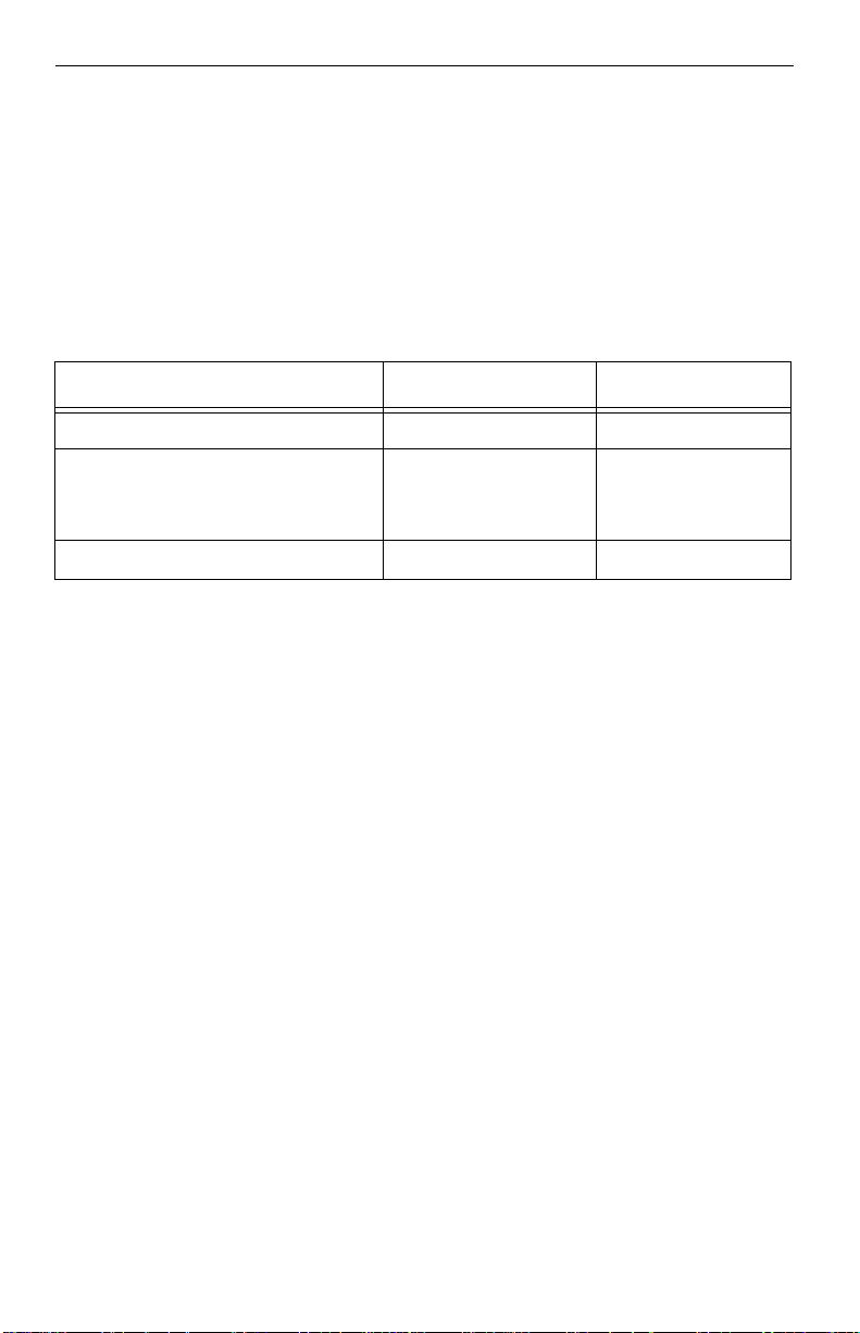
2.11 Acoustics
Drive acoustics are measured as overall A-weig hted acoustic sound power
levels (no pure tones). All measurements are consistent with ISO document
7779. Sound power measurements are taken under essentially free-field
conditions over a reflecti ng plane. For all tests, the drive is orient ed with th e
cover facing upw ar d.
Note. For seek mode tests, the drive is placed in seek mode only. The number
of seeks per second is defined by the following equation:
(Number of seeks per second = 0.4 / (average latency + average access time)
Table 1: Fluid Dynamic Bearing (FDB) motor acoustics
Acoustic mode
Models Idle* Quiet seek Performance seek
ST3120023A and
ST380023A
ST360015A,
ST340017A and
ST330013A
*During periods of drive idle, some offline activity may occur according to the S.M.A.R.T.
specification, which may increase acoustic and power to operational levels.
2.5 bels (typ)
2.7 bels (max)
2.1 bels (typ)
2.3 bels (max)
2.85 bels (typ)
3.05 bels (max)
2.45 bels (typ)
2.65 bels (max)
3.4 bels (typ)
3.7 bels (max)
3.1 bels (typ)
3.5 bels (max)
Page 27

Barracuda ATA V Product Manual, Rev. E 17
2.12 Electromagnetic immunity
When properly ins talled in a represen tative host system , the drive operates
without errors or degradation in performance when subjected to the radio
frequency (RF) environments defined in the following table:
Performance
Test Description
Electrostatic
discharge
Radiated RF
immunity
Electrical fast
transient
Surge
immunity
Conducted
RF immunity
Voltage dips,
interrupts
Contact, HCP, VCP: ± 4
Air:
± 8 kV
80 to 1,000 MHz, 3 V/m,
80% AM with 1 kHz sine
900 MHz, 3 V/m, 50% pu lse
modulation @ 200 Hz
± 1 kV on AC mains, ± 0.5
kV on external I/O
± 1 kV differential, ± 2 kV
common, AC mains
150 kHz to 80 MHz, 3 Vrms,
80% AM with 1 kHz sine
0% open, 5 seconds
0% short, 5 seconds
40%, 0.10 seconds
70%, 0.01 seconds
level
kV;
B EN 61000-4-2: 95
A EN 61000-4-3: 96
B EN 61000-4-4: 95
B EN 61000-4-5: 95
A EN 61000-4-6: 97
C
C
C
B
2.13 Reliability
Nonrecoverable read errors 1 per 10
Mean time between failures 600,000 power-on hours
(nominal power, 25°C ambient temperature)
Contact start-stop cycles 50,000 cycles
(at nominal v oltage and tempe rature , with 6 0 cycles
per hour and a 50% duty cycle)
14
bits read, max.
Reference
standard
ENV 50204: 95
EN 61000-4-11: 94
Preve nti ve maintenance None required
Page 28

18 Barracuda ATA V Product Manual, Rev. E
2.14 Agency certification
2.14.1 Safety certification
The drives are recognized in accordance with UL 1950 and CSA C22.2 (950)
and meet all applic able s ections of IE C950 a nd EN 60950 a s test ed by T UV
North America.
2.14.2 Electromagnetic compatibility
Hard drives that displ ay the CE mark co mply with the European Union (EU)
requirements specified in the Electromagnetic Compatibility Directive (89/336/
EEC). Testing is pe rformed to the lev els specified by the product s tandards
for Information Techn ology Equi pment (I TE). Emissio n levels are defined by
EN 55022, Class B and the immunity levels are defined by EN 55024.
Seagate uses an indepen dent laborato ry to confirm co mpliance with the EC
directives specifie d in th e pr ev iou s para gr aph . Driv es are te st ed in re pres entative end-user systems. Although CE-marked Seagate drives comply with the
directives when used in the test systems, we cannot guarantee that all systems
will comply with the di rectives. The drive is desig ned for operation inside a
properly designed enc losure, with properl y shielded I/O cab le (if necessary)
and terminators on all unused I/O ports. Computer manufacturers and system
integrators should confirm EMC compliance and provide CE marking for their
products.
Korean RRL
If these drives have the Korea Ministry of Information and Communication
(MIC) logo, they comply with paragraph 1 of Article 11 of the Electromagnetic
Compatibility control Re gulation a nd meet the E lectromagn etic Compa tibility
(EMC) Framework requirements of the Radio Research Laboratory (RRL)
Ministry of Information and Communication Republic of Korea.
These drives have been tested and comply with the Electromagnetic Interference/Electromagneti c Susceptib ility (EMI/EMS ) for Class B produc ts. Drives
are tested in a representative, end-user system by a Korean-recognized lab.
• EUT name (model numbers): ST3120023A, ST380023A, ST360015A,
ST340017A, and ST330013A
• Certificate numbers: ST3120023A E-H011-02-2918
ST380023A E-H011-02-2916
ST360015A E-H011-02-2917
ST330013A E-H011-02-2919
• Trade name or applicant: Seagate Technology
• Manufacturer/nationality: Singapore
Page 29

Barracuda ATA V Product Manual, Rev. E 19
Australian C-Tick (N176)
If these models have the C-Tick marking, they comply with the Australia/New
Zealand Standard AS/NZS3548 1995 and meet the Electromagnetic Compatibility (EMC) Fram ework require ments of the A ustralian Commu nication Authority (ACA).
2.14.3 FCC verification
These drives are intended to be contained solely within a personal computer or
similar enclosure (not attached as an external device). As such, each drive is
considered to be a subassembly even when it is individually marketed to the
customer. As a subassembly, no Federal Communications Commission verification or certification of the device is required.
Seagate Technology L LC has tested this devi ce in enclosures as described
above to ensure that the total assembl y (enclo sure , disc dri ve, moth erboa rd,
power supply, etc.) does comply with the limits for a Class B computing device,
pursuant to Subpart J, Part 15 of the FCC rules. Op eration with nonc ertified
assemblies is likely to result in interference to radio and television reception.
Radioand televisioninterference. This equipment generates and uses radio
frequency energy and if not installed and used in st rict accorda nce with the
manufacturer’s instructions, may caus e interference to radio and telev ision
reception.
This equipment is designed to provide reasonable protection against such
interference in a residenti al instal lation. Ho wever, ther e is no g uarantee that
interference will no t occur in a particular in stallation. If this equipm ent does
cause interference to radio or tel ev isio n, whi ch can be determ ine d by turn in g
the equipment on and off, you are encouraged to try one or more of the
following corrective measures:
• Reorient the receiving antenna.
• Move the device to one side or the other of the radio or TV.
• Move the device farther away from the radio or TV.
• Plug the computer into a diff erent outlet so th at the receive r and compu ter
are on different branch outlets.
If necessary, you should consult your dealer or an experienced radio/television
technician for additional suggestions. You may find helpful the following
booklet prepared by the Federal Communications Commission: How toIdentify
andResolveRadio-Television Interference Problems. This booklet is available
from the Superintendent of Documents, U.S. Government Printing Office,
Washington, DC 20402. Refer to publication number 004-000-00345-4.
Page 30

20 Barracuda ATA V Product Manual, Rev. E
Page 31

Barracuda ATA V Product Manual, Rev. E 21
3.0 Configuring and mounting the drive
This section conta ins the specificatio ns and instructions f or configuring and
mounting the drive.
3.1 Handling and static discharge precautions
After unpacking, and before installation, the drive may be exposed to potential
handling and electrostatic discharge (ESD) hazards. Observe the following
standard handling and static-discharge precautions:
Caution:
• The SeaShell™ replaces electrostatic discharge (ESD) bags. The SeaShell
package is a shock-ribbed, transparent clamshell enclosure that limits a
drive’s exposure to ESD and also protects against external shocks and
stresses. The desig n permits attac hing cable s, software loading and la bel/
barcode scanning without removing the drive from the SeaShell. This
minimizes handling da mage. Keep the dr ive in the SeaSh ell package until
you are ready for installation.
• The drive has a cover called SeaShield
cover—it protec ts the drive from electrosta tic discharge (ESD) and mi nor
impact damage. Removing the SeaShield voids the warranty.
• Before handling the drive, put on a grounded wrist strap, or ground yourself
frequently by touching the metal chassis of a com puter that is plugged int o
a grounded outlet. Wear a grounded wrist strap throughout the entire
installation procedure.
• Handle the drive by its edges or frame only.
• The drive is extremely fragile—handle it with care. Do not press down on the
drive top cover.
• Always rest the drive on a padded, antistatic surface until you mount it in the
computer.
• Do not touch the connector pins or the printed circuit board.
• Do not remove the factory-installed labels from the drive or cover them with
additional labels. Removal voids the warranty. Some factory-installed labels
contain information n eeded to service the drive. Ot her labels are used to
seal out dirt and contamination.
. Do not remove this permanent
Page 32

22 Barracuda ATA V Product Manual, Rev. E
3.2 Jumper settings
3.2.1 Master/slave configuration
The options jumper block shown in Figure 3 is used to configure the drive for
operation. It is the 8-pin dual header between the interface connector and the
power connector. Use the following settings to configure the drive as a master
or a slave.
Master or single drive. The drive is configured at the factory for a master or
single-drive operation with a jumper set on pins 7 and 8.
Driveasslave. Remove all jumpers.
Drive as master with a non-ATA-compatible slave.
Use this jumper setting only if the drive do es not work as a master with n o
jumpers installed.
Options jumper block
Master or single drive
Drive is slave
Master with non ATAcompatible slave
Cable select
Limit drive capacity
to 32 Gbytes
1753
684
2
Circuit Board
Figure 3. Master/slave jumper settings
3.2.2 Cable-select option
Computers that use cable select determine the master an d slave drives by
selecting or deselecting pin 28, CSEL, on the interface bus. Master and slave
drives are determined by their physical position on the cable. To enable cable
select, set a jumper on pins 5 and 6 as shown in Figure 3. Refer to your
computer manual to determine whether your computer supports this option.
Page 33

Barracuda ATA V Product Manual, Rev. E 23
3.2.3 Alternate capacity jumper
Some older computers may “hang” at startup if their BI OS det ects a di sc dr ive
with a capacity gr eater than 32 Gbyt es. This l imits the d rive’s capacity to 32
Gbytes when the alternate capacity jumper is used. To access the full capacity
of the drive, you can:
• Update the BIOS
™
• Use third-party software such as DiscWizard
or Disk Manager
• Use a third-party host adapter
For drives with capacities greater than 32 Gbytes, the alternate capacity jumper
changes the total available LBA sectors to 32 Gbytes to solve issues with some
BIOS during power on. The ATA Set Features subcommand “F1
Report Full
H
Capacity Available” causes Identify Data words 60 and 61 to report the f ull
capacity. See Section 4.1.3 on page 33 for more details on the Set Features
command.
Windows XP, Windows Me, Windows 98 or newer versions are needed to
support drives with capacities greater than 32 Gbytes.
3.2.4 Ultra ATA/100 cable
An 80-conductor 40 -pin cable is required to r un Ultra DMA mode 3, mode 4
and mode 5. This cabl e uses even-numbered condu ctors connected to the
ground pins to improve signal integrity.
Note. If you are using a 40-pin 80-conductor
Master
Slave
Figure 4. Ultra ATA cable connectors
Pin 1
Computer
Motherboard
cable, attach the blue connector to the
motherboard, the black connector to the
master drive, and the grey connector
to the slave.
Note. The drive supports both host and drive cable detection. The host
detects the 80-conductor cable by sampling pin 34, CBLID–, o n the
interface bus. The drive detects the 80-conduct or cable by sensing a
capacitor at the host side through the CBLID– signal. The result is
reported i n a Fast Rise Detected bit ( bit 13 of word 93 in the Ident ify
drive parameter block).
Page 34

24 Barracuda ATA V Product Manual, Rev. E
3.3 Drive mounting
You can mount the drive in any orientation using four screws in the sidemounting holes or four screws in the bottom-mounting holes. See Figure 5 for
drive mounting dimensions. Follow these important mounting precautions
when mounting the drive:
• Allow a minimum cle arance of 0.030 inches (0 .76 mm) around the entir e
perimeter of the drive for cooling.
• Use only 6-32 UNC mounting screws.
• Use only .045” +/ - .005 high by .050” diame ter bosses (4x) for bottom mountin g
applications to prevent defo rmat ion of the Sea Shiel d.
• Do not overtighten the mounting screws (maximum torque: 6 inch-lb).
• Do not use a drive interface cable that is more than 18 inches long.
Notes:
1. Dimensions are shown in inches (mm).
2 Dimensions per SFF-8301 specification.
3 Dimension measured from bottom of SeaShield.
Recommended
case temperature
measurement location
1.028 max
(26.11)
3 x 0.25 0.015
(6.35 0.037)
both sides
1.122 0.02
(28.5 0.51)
1.638 0.01
(41.61 0.25)
3 x 6-32 UNC-2B
.225 (5.71) max. fastener
penetration both sides. 3 threads
minimum engagement.
3
3
2
4.0 0.01
(101.60 0.25)
5.787 max
(146.99)
0.218
(5.54)
3
2.23
(56.56)
2.83
(71.80)
3.71
(94.35)
0.125 0.01
(3.18 0.25)
3.75 0.01
(95.25 0.25)
4.0 0.01
(101.60 0.25)
Figure 5. Mounting dimensions—top, side and end view
0.168
(4.27)
3
1.625 0.02
(41.28 0.51)
1.75 0.01
(44.45 0.25)
4 x 6-32 UNC-2B
.250 (6.35) max. fastener
penetration. 3 threads
minimum engagement.
Recommended
case temperature
measurement location
Page 35

Barracuda ATA V Product Manual, Rev. E 25
4.0 A TA interface
These drives use the industry -standard A TA task file interface tha t supports
16-bit data transfers . It supports ATA program med in put /output (PIO) modes
0–4; multiword DM A modes 0–2, and Ultr a DMA modes 0–5. The dr ive als o
supports the use of the IORDY signal to provide reliable high-speed data
transfers.
You can use a daisy-chain cable to connect two drives to a single AT host bus.
For detailed information about the ATA interface, refer to the draft of AT
Attachment with Packet Interface Extension (ATA/ATAPI-5), NCITS T13
1153D, subsequently referred to as the Draft ATA-5 Standard.
4.1 ATA interface signals and connector pins
Figure 6 on page 26 summ arizes the s ignals on the ATA interface connector
that the drive suppor ts. For a detailed description of the se signals, refer to
the Draft ATA-5 Standard.
Page 36

26 Barracuda ATA V Product Manual, Rev. E
Drive pin #
10
11
12
13
14
15
16
17
18
19
20
21
22
23
24
25
26
27
28
29
30
31
32
33
34
35
36
37
38
39
40
Signal name
–
1
2
3
4
5
6
7
8
9
Reset
Ground
DD7
DD8
DD6
DD9
DD5
DD10
DD4
DD11
DD3
DD12
DD2
DD13
DD1
DD14
DD0
DD15
Ground
(removed)
DMARQ
Ground
DIOW–
STOP
Ground
DIOR
–
HDMARDY
HSTROBE
Ground
IORDY
DDMARDY–
DSTROBE
CSEL
–
DMACK
Ground
INTRQ
–
IOCS16
DA1
–
PDIAG
CBLID–
DA0
DA2
–
CS0
–
CS1
–
DASP
Ground
–
Host pin # and signal description
1
Hardware Reset
2
Ground
3
Host Data Bus Bit 7
4
Host Data Bus Bit 8
5
Host Data Bus Bit 6
6
Host Data Bus Bit 9
7
Host Data Bus Bit 5
8
Host Data Bus Bit 10
9
Host Data Bus Bit 4
10
Host Data Bus Bit 11
11
Host Data Bus Bit 3
12
Host Data Bus Bit 12
13
Host Data Bus Bit 2
14
Host Data Bus Bit 13
15
Host Data Bus Bit 1
16
Host Data Bus Bit 14
17
Host Data Bus Bit 0
18
Device Data (15:0)
19
Ground
(No Pin)
20
21
DMA Request
22
Ground
23
Device I/O Write:
Stop Ultra DMA Burst
24
Ground
25
Device I/O Read:
Host Ultra DMA Ready:
Host Ultra DMA Data Strobe
26
Ground
27
I/O Channel Ready
Device Ultra DMA Ready
Device Ulta DMA Data Strobe
28
Cable Select
29
DMA Acknowledge
30
Ground
31
Device Interrupt
32
Reserved
33
Host Address Bus Bit 1
34
Passed Diagnostics
Cable Assembly Type Identifier
35
Device Address (2:0)
36
Device Address (2:0)
37
Chip Select (1:0)
38
Chip Select (1:0)
39
Drive Active/Slave Present
40
Ground
Pins 28, 34 and 39 are used for master-slave communication (details shown below).
28
34
39
Drive 0 (master)Drive 1 (slave)
28
34
39
CSEL
PDIAG
DASP–
–
Host
28
34
39
Figure 6. I/O pins and supported ATA signals
Page 37

Barracuda ATA V Product Manual, Rev. E 27
4.1.1 Supported ATA commands
The following table lists ATA-standard commands that the drive supports. For
a detailed description of the ATA commands, refer to the DraftATA-5 Standard.
See “S.M.A.R.T. commands” on page 35 for details and subcommands used
in the S.M.A.R.T. implementation.
Command name Command code (in hex)
ATA-standard commands
Download Microcode 92
Execute Device Diagnostics 90
Flush Cache E7
Identify Device EC
Initialize Device Parameters 91
Read Buffer E4
Read DMA C8
Read Multiple C4
Read Native Max Addess F8
Read Sectors 20
Read Verify Sectors 40
Seek 70
Set Features EF
Set Max F9
Note: Individual Set Max commands
are identified b y the v alue pl aced in the
Set Max Features Register as defined
to the right.
Freeze Lock 04
Set Multiple Mode C6
S.M.A.R.T. B0
Write Buffer E8
Write DMA CA
H
H
H
H
H
H
H, C9H
H
H
H, 21H
H, 41H
H
H
H
Address: 00
Password: 01
Lock: 02
Unlock: 03
H
H
H
H
H, CBH
H
H
H
H
Page 38

28 Barracuda ATA V Product Manual, Rev. E
Command name Command code (in hex)
Write Multiple C5
Write Sectors 30
H
H, 31H
ATA-standard power-management commands
Check Power Mode 98H or E5
Idle 97H or E3
Idle Immediate 95H or E1
Sleep 99H or E6
Standby 96H or E2
Standby Immediate 94H or E0
ATA-standard security commands
Security Set Password F1
Security Unlock F2
Security Erase Prepare F3
Security Erase Unit F4
Security Freeze Lock F5
Security Disable Password F6
H
H
H
H
H
H
H
H
H
H
H
H
4.1.2 Identify Device command
The Identify Device command (command code EC
) transfers information
H
about the drive to the host followin g power up. The data is organized as a
single 512-byte block of data, whose contents are shown in the table on
page 27. All reserved bits or words sh ould be set to zero. Parame ters listed
with an “x” are drive-specific or vary with the state of the drive. See Section
2.0 on page 3 for default parameter settings.
The following commands contain drive-specific features that may not be
included in the Draft ATA-5 Standard.
Page 39

Barracuda ATA V Product Manual, Rev. E 29
Word Description Value
Configuration information:
0C5A
• Bit 15: 0 = ATA; 1 = ATAPI
0
• Bit 7: removable media
• Bit 6: removable controller
• Bit 0: reserved
1 Number of logical cylinders 16,383
2 ATA-reserved 0000
3 Number of logical heads 16
4 Retired 0000
5 Retired 0000
6 Number of logical secto rs per logical
003F
track: 63
7–9 Retired 0000
10–19 Seri al number: (20 ASCII characters,
0000
= none)
H
ASCII
20 R etired 0000
21 R etired 0400
22 Obsolete 0000
23–26 Firmware revision (8 ASCII character
x.xx
string, padded with blanks to end of
string)
H
H
H
H
H
H
H
H
H
27–46 Drive model number: (40 ASCII charac-
ters, padded with blanks to end of string)
ST3120023A
ST380023A
ST360015A
ST340017A
ST330013A
47 (Bits 7–0) Maximum sectors per i nterrupt
8010
on Read multiple and Write multiple (16)
48 Reserved 0000
49 Standard Standby timer, IORDY sup-
2F00
ported and may be disable d
50 ATA-reserved 0000
H
H
H
H
Page 40

30 Barracuda ATA V Product Manual, Rev. E
Word Description Value
51 PIO data-transfer cycle timing mode 0200
52 R etired 0200
53 Words 54–58, 64–70 and 88 are valid 0007
54 N umber of current logical cylinders xxxx
55 Number of current logical heads xxxx
56 N umber of current logical sectors per
xxxx
logical track
57–58 Current capacity in sectors xxxx
59 N umber of sectors transferred during a
xxxx
Read Multiple or Write Multiple com-
mand
60–61 Total number of user-addressable LBA
sectors available
(see Section 2.2 for related information)
ST3120023A = 234,441,648
ST380023A = 156,301,488
ST360015A = 117,231,408
ST340017A = 78,165,360
ST330013A = 58,633,344
62 R etired 0000
63 Multiword DMA active and modes sup-
xx07
ported (see note following this table)
H
H
H
H
H
H
H
H
H
H
64 Advanced PIO modes supported (modes
0003
3 and 4 supported)
65 Minimum multiword DMA transfer cycle
0078
time per word (120 nsec)
66 Recommended multiword DMA transfer
0078
cycle time per word (120 nsec)
67 Minimum PIO cycle time without IORDY
00F0
flow control (240 nsec)
68 Minimum PIO cycle time with IORDY
0078
flow control (120 nsec)
69–74 ATA-reserved 0000
75 Queue depth 0000
H
H
H
H
H
H
H
Page 41

Barracuda ATA V Product Manual, Rev. E 31
Word Description Value
76–79 ATA-reserved 0000
80 Major version number 003E
81 Minor version number 0000
82 C ommand sets supported 306B
83 C ommand sets supported 4001
84 C ommand sets support extension 4000
85 Command sets enabled 30xx
86 Command sets enabled 0001
87 Command sets enable extension 4000
88 U ltra DMA support and current mode
xx3F
(see note following this table)
89 Security erase time 0000
90 Enhanced security erase time 0000
91 Advanced power management value 0040
92 Master password revision code FFFE
93 H ardware reset value (see description
xxxx
following this table)
H
H
H
H
H
H
H
H
H
H
H
H
H
H
H
94 Auto acoustic management setting xxxx
95–127 ATA-reserved 0000
128 Security status 0001
129–159 Seagate-reserved xxxx
160–254 ATA-reserved 0000
255 Integrity word xxA5
H
H
H
H
H
H
Page 42

32 Barracuda ATA V Product Manual, Rev. E
Note. S ee the bit descrip tions below for words 63, 88, 93 and 94 of the
Identify Drive data:
Description (if bit is set to 1)
Bit Word 63
0 Multiword DMA mode 0 is supported.
1 Multiword DMA mode 1 is supported.
2 Multiword DMA mode 2 is supported.
8 Multiword DMA mode 0 is currently active.
9 Multiword DMA mode 1 is currently active.
10 Multiword DMA mode 2 is currently active.
Bit Word 88
0 Ultra DMA mode 0 is suppo rted.
1 Ultra DMA mode 1 is suppo rted.
2 Ultra DMA mode 2 is suppo rted.
3 Ultra DMA mode 3 is suppo rted.
4 Ultra DMA mode 4 is suppo rted.
8 Ultra DMA mode 0 is currently active.
9 Ultra DMA mode 1 is currently active.
10 Ultra DMA mode 2 is currently active.
11 Ultra DMA mode 3 is currently active.
12 Ultra DMA mode 4 is currently active.
13 Ultra DMA mode 5 is currently active.
Bit Word 93
13 1 = 80-conductor cable detected, CBLID above V
0 = 40-conductor cable detected, CBLID below VIL
Bit Word 94
0–7 Current AAM setting
8–15 AAM Power on default
IH
Page 43

Barracuda ATA V Product Manual, Rev. E 33
4.1.3 Set Features command
This command control s the imple mentation o f var ious f eatures t hat the d rive
supports. When th e drive receives this command , it sets BSY, checks the
contents of the Features register, clears BSY and generates an interrupt. If the
value in the regis ter do es no t r epres en t a feat ur e th at t he d r iv e sup por ts , th e
command is aborted. Po wer-on default has the read look-ahead and writ e
caching features enabled. The acceptable values for the Features register are
defined as follows:
02
03
05
42
55
82
Enable write cache (default).
H
Set transfer mode (based on Sec tor Count register value).
H
00
Set PIO mode to default (PIO mode 2).
H
01
Set PIO mode to default and disable IORDY (PIO mode 2).
H
08
PIO mode 0
H
09
PIO mode 1
H
0A
PIO mode 2
H
0B
PIO mode 3
H
0C
PIO mode 4 (default)
H
20
Multiword DMA mode 0
H
21
Multiword DMA mode 1
H
22
Multiword DMA mode 2
H
40
Ultra DMA mode 0
H
41
Ultra DMA mode 1
H
42
Ultra DMA mode 2
H
43
Ultra DMA mode 3
H
44
Ultra DMA mode 4
H
45
Ultra DMA mode 5
H
Enable advanced power management.
H
Auto acoustic management (based on section count register value).
H
FE
Performance seek
H
80
Quiet acoustic seek
H
Disable read look-ahead (read cache) feature.
H
Disable write cache.
H
Page 44

34 Barracuda ATA V Product Manual, Rev. E
AA
F1
Enable read look-ahead (read cache) feature (default).
H
Report full capacity avai lable.
H
Note. At power-on, or after a hardware or software reset, the default values
of the features are as indicated above.
Page 45

Barracuda ATA V Product Manual, Rev. E 35
4.1.4 S.M.A.R.T. commands
S.M.A.R.T. provides near-term failure prediction for disc drives. When
S.M.A.R.T. is enabled, the d rive monitors predetermine d drive attribut es that
are susceptible to degradation over time. If self-monitoring determines that a
failure is like ly, S.M .A. R.T . ma kes a st atus rep ort av ailab le t o th e host. No t all
failures are predictable. S.M.A.R.T. predictability is limited to the attributes the
drive can monitor. For more information on S.M.A.R.T. commands and implementation, see the Draft ATA-5 Standard.
SeaTools diagnostic software activates a built-i n drive self-test (DST S.M.A.R. T.
command for D4
) that eliminates unnecessary drive returns. The diagnostic
H
software ships with all new drives a nd is al so ava ilable at:
http://seatools.sea
gate.com.
This drive is ship ped with S.M.A.R.T. features disabled. Y ou must have a
recent BIOS or software package that supports S.M.A.R.T. to enable this
feature. The table below shows the S.M.A.R.T. command codes that the drive
uses.
Code in features
register S.M.A.R.T. command
D0
D1
D2
D3
D4
D5
D6
D7
D8
D9
DA
H
H
H
H
H
H
H
H
H
H
H
S.M.A.R.T. Read Data
Vendor-specific
S.M.A.R.T. Enable/Disable Attribute Auto save
S.M.A.R.T. Save Attribute Values
S.M.A.R.T. Execute Off-line Immediate (runs DST)
S.M.A.R.T. Read Log Sector
S.M.A.R.T. Write Log Sector
Vendor-specific
S.M.A.R.T. Enable Opera tio ns
S.M.A.R.T. Disable Op erations
S.M.A.R.T. Return Status
Note. If an appropriate code is not written to the Features Register, the
command is aborted and 0x04 (abort) is written to the Error register.
Page 46

36 Barracuda ATA V Product Manual, Rev. E
Page 47

Barracuda ATA V Product Manual, Rev. E 37
5.0 Seagate Technology support services Online Services
Internet
www.seagate.com for information about Seagate products and services.
Worldwide suppor t is available 24 hours daily by e-mail for your disc or tape
questions.
Presales Support:
Disc: www.seagate.com/support/email/email_presales.html or
DiscPresales@Seagate.com
Tape: www.seagate.com/support/email/email_tape_presales.html or
Tape_Sales_Support@Seagate.com
Technical Support:
Disc: www.seagate.com/support/email/email_disc_support.html or
DiscSupport@Seagate.com
Tape: www.seagate.com/support/email/email_tape_support.html or
TapeSupport@Seagate.com
Reseller Marketplace
Reseller Marketplace is the storage industry’s first collaborative, e-commerce
marketplace offering resellers the fastest, most efficient online purchasing
process for Seagate storage solutio ns. The Reseller Marketplace at ma rketplace.seagate.com, an exclusive ser vice for US reselle rs par ticipating in the
Seagate Partner Pr ogram (SPP), is designed to stream line the purchasing
process of Seagate soluti ons and provide unprecedented value to Seagat e
resellers through real-time pr icing and availability, fa st and easy com parison
shopping, and seamless integration with key distributors for a one-stop shopping experience.
For support, questions and comments: reseller.seagate.com/benefits/T1.html
or 1-877-271-3285 ( toll-free) 9
A.M. to 7 P.M. (eastern ti me) Monday through
Friday.
Ta pe Purchases
US customers ca n purchase S eagate data ca r tridges, tap e supplies, acces sories, and select Seagate tape drive products 24 hours daily at
buytape.seagate.com.
Automated Services
SeaFONE®(1-800-SEAGATE) is the Seagat e toll-free number (1-800-732-
4283) to access our automated self-help services. Using a touch-tone phone,
you can find answers to service phone numbers, commonly asked questions,
troubleshooting tips and specifications for disc drives and tape drives 24
Page 48

38 Barracuda ATA V Product Manual, Rev. E
hours daily. International callers can reach this service by dialing +1-405936-1234.
SeaFAX
Using a touch-tone p hone, you can obtain technical s upport informati on by
return FAX 24 hours daily.
®
(1-800-SEAGATE) is the Seagate automated FAX delivery system.
Presales Support
Presales Support
Our Presales Support staff can help you determine which Seagate products
are best suited for your specific application or computer system.
Technical Support
If you need help installing your drive, consult your dealer. Dealers are familiar
with their unique sys tem configurations and can hel p you with system conflicts and other technical issues. If you need additional help, you can talk to a
Seagate technical support specialist. Before calling, note your system configuration and drive model number (ST####).
SeaTDD™ (+1-405-936-1687) is a telecommunicati ons device for the deaf
(TDD). You can send questi ons or comments 24 hours daily and exchange
messages with a technical support specialist from 8:00
1:00
P.M. to 6:00 P.M. (central time) Monday through Friday.
A.M. to 11:45 A.M. and
Customer Service (CSO)
Warranty Service
Seagate offers worldwide customer support for Seagate drives. Seagate
direct OEM, Distribution and System Integrator customers should contact
their Seagate ser vice center representa tive for warranty information . Other
customers should contact their place of purchase.
Authorized Service Centers
If you live outside the US, you can contact an Authorized Service Cente r for
service.
Page 49

Barracuda ATA V Product Manual, Rev. E 39
USA/Canada/Latin America Support Services
Presales Support
Call Center Toll-free Direct dial FAX
Disc: 1-877-271-3285 +405-936-1210 +1-405-936-1683
Tape: 1-800-626-6637 +1-714-641-2500 +1-714-641-2410
Technical Support (SeaFONE)
1-800-SEAGATE or +1-405-936-1234 (for specific product phone number)
FAX: Disc: +1-405-936-1685; Tape and Server Appliance: +1-405-936-1683
SeaFAX 1-800-SEAGATE
SeaTDD +1-405-936-1687
Warranty Service
Call Center Toll-free Direct dial FAX / Internet
USA, Mexico and 1-800-468-3472 +1-405-936-1456 +1-405-936-1462
Latin America
Canada
Memofix1 1-800-636-6349 +1-905-660-4936 +1-905-660-4951
www.memofix.com
Adtech* 1-800-624-9857 +1-905-890-3099 +1-905-812-3977
www.adtech1.com
Brazil
MA Centro
de Serviços* — +55-21-2509-7267 +55-21-2507-6672
e-mail: centro.de.servicos.brasil@seagate.com
European Support Services
For European customer support, dial the toll-free number for your specific
country for presales s upport, technical suppor t, SeaFAX and warranty service.
If your country is not listed here, dial our European call center at +31-20-3167222 from 8:30
day. The European call center is located in Amsterdam, The Netherlands.
Call Center
Austria 0 800-20 12 90
Belgium 0 800-74 876
Denmark 80881266
France 0 800-90 90 52
Germany 0 800-182 6831
1Authorized Service Centers
A.M. to 5:00 P.M. (European central time) Monday through Fri-
Page 50

40 Barracuda ATA V Product Manual, Rev. E
Ireland 1 800-55 21 22
Italy 800-790695
Netherlands 0 800-732 4283
Norway 800-113 91
Poland 00 800-311 12 38
Spain 900-98 31 24
Sweden 0 207 90 073
Switzerland 0 800-83 84 11
Turkey 00 800-3192 91 40
United Kingdom 0 800-783 5177
FAX Services—All European Countries
Presales/Technical Support/WarrantyService31-20-653-3513
Africa/Middle East Support Services
For presales, technical suppor t, warranty ser vice and FAX services in Afri ca
and the Middle East, dial our Europe an call cen ter at +31-20 -316-7222 from
8:30
A.M. to 5:00 P.M. (European central time) Monday through Friday, or
send a FAX to +31-20-653-3513. The European call center is located in
Amsterdam, The Netherlands.
Asia/Pacific Support Services
For Asia/Pacific presales and tec hnical suppor t, dial the toll-free numb er for
your specific country. The Asia/Pacific toll-free numbers are available from
6:00
A.M. to 10:45 A.M. and 12:0 0 P.M. to 6:00 P.M. (Australian eastern tim e)
Monday through Friday. If your country is not listed here, direct dial one of our
technical support locations.
Call Center Toll-free Direct dial FAX
Australia 1800-14-7201 ——
China ——+86-10-6871-4316
Hong Kong 800-90-0474 — +852-2368 7173
India1 1-600-33-1104 ——
Indonesia 001-803-1-003-2165 ——
Japan ——+81-3-5462-2978
Malaysia 1-800-80-2335 ——
New Zealand 0800-443988 ——
Singapore 800-1101-150 — +65-6488-7525
Taiwan — +886-2-2514-2237 +886-2-2715-2923
Thailand 001-800-11-0032165 ——
1Authorized Service Center
Page 51

Barracuda ATA V Product Manual, Rev. E 41
Warranty Service
Call Center Toll-free Direct dial FAX
Asia/Pacific — +65-6485-3595 +65-6485-4860
Australia 1800-12-9277 ——
Page 52

42 Barracuda ATA V Product Manual, Rev. E
Page 53

Barracuda ATA V Product Manual, Rev. E 43
Index
Numerics
3D Defense System 1
A
acoustics 16
Active mode
adio frequency (RF)
agency certification (regulatory)
alternate capacity jumper
altitude
ambient co nditions
ambient temperatu re
areal density
ATA interface
ATA-standard commands
Australian C-Tick
autodetection
average seek time
B
BIOS 23
BPI
7
buffer
burst
1
C
cable 23
cable select
cache
case temperature
CE mark
certification
Check Power Mode
commands
compliance
conducted noise
conducted RF immunity
configuring the drive
12
17
23
14
3
8, 13
1, 7
25
27
19
1
8
1, 7
1, 22
1, 7
13
18
18
28
27
18
12
17
21
18
connector pins
connectors
contact start-stop cycles
CSA C22.2 (950)
CSEL
22
C-Tick
19
current profile
cycles
17
25
23
17
18
11
D
Data Defense 1
data-transfer rates
DC power
density
Diagnostic Defense
diagnostic software
discs
DiscWizard
Disk Manager
dissipation
Download Microcode
Drive Defense
drive diagnostics
drive monitoring
drive self-test
DST
8
7
6
23
10
35
1
1
1, 35
23
27
1
8
1
1, 35
E
electrical fast transient 17
electromagnetic compatibility
Electromagnetic Compatibility Direc-
tive
18
electromagnetic immunity
electrostatic discharge
EMC compliance
EN 60950
enclosures
environmental specifications
EPRML
error-correction algorithms
errors
European Union
18
1, 7
17
18
19
18
18
17
1, 17
13
1
Page 54

44 Barracuda ATA V Product Manual, Rev. E
Execute Device Diagnostics 27
F
failure prediction 35
FCC verification
Features register
Flush Cache
formatted capacity
frequency
19
33
27
6
17
G
GMR 1
guaranteed sectors
6
H
handling 21
heads
1, 6
height
7
humidity
14
I
I/O data-transfer rate 7
Identify Device command
Idle
10, 28
Idle and Standby timers
Idle Immediate
Idle mode
Idle mode power
IEC950
Information Technology Equipment
Initialize Device Parameters
interface
interface signals
interference
interleave
internal data-transfer rate OD
ISO document 7779
18
28
12
9
18
7, 25
25
19
7
27, 28
13
27
7
16
J
jumper settings 22
K
Korean RRL 18
L
LBA mode 6
length
7
logical geometry
6
M
maintenance 17
master
22
master/slave
maximum temperature
mean time between failures (MTBF)
modes
monitoring
mounting the drive
1, 22
13
17
25
1
21, 24
N
noise 12
nominal power
nonoperating shock
nonoperating vibration
nonrecoverable read errors
3
15
15
O
operating 10
operating power and current
operating shock
operating vibration
orientation
15
15
24
P
physical characteristics 7
physical organization
6
17
9
Page 55

Barracuda ATA V Product Manual, Rev. E 45
pins 25
PIO
25
power consumption
power dissipation
power management
power specifications
power-management comma nds
power-management modes
power-on to ready
precautions
preventive maintenance
programmable power management
24
12
9
10
12
8
28
12
8
17
R
radiated RF immunity 17
radio and television interference
random track location
Read Buffer
Read DMA
read errors
Read Multiple
Read Sectors
Read Verify Sectors
read/write heads
read/write power and current
recording and interface technology
recording density
recording heads
recording method
register
relative humidity
reliability
resistance
resistive load
RF
17
27
27
17
1, 27
27
7
33
17
12
12
9
27
6
7
1
7
14
19
9
S
S.M.A.R.T. 27
S.M.A.R.T. commands
S.M.A.R.T. drive monitoring
35
1
safety certification
screws
SeaShell
SeaShield
SeaTools
sectors
security commands
Security Disable Password
Security Erase Prepare
Security Erase Unit
Security Freeze Lock
Security Set Password
Security Unlock
Seek
seek mode
seek time
Seeking
servo electronic s
Set Features command
Set Multiple Mode
shock
signals
single-track seeks
slave
Sleep
Sleep mode
sound
specifications
spindle speed
spinup
spinup power
Standby
Standby Immediate
Standby mode
standby to ready
start/stop times
start-stop cycles
static-discharge precautions
stop times
subassembly
support services
surge immunity
24
21
1, 21
1, 35
6
27
9
8
10
15
25
22
10, 28
13
16
3
7
10
9
10, 28
9, 12
8
19
18
28
28
28
28
28
28
28
9
27, 33
27
8
28
8
8
17
21
37
17
Page 56

46 Barracuda ATA V Product Manual, Rev. E
T
technical support servic es 37
temperature
temperature gradient
timers
track density
track-to-track seek time
TUV North America
13
14
13
7
8
18
U
UL 1950 18
Ultra ATA/100
Ultra DMA
23
23
V
vibration 15
voltage
voltage dips, interrupts
voltage tolerance
12
17
12
W
weight 7
wet bulb temperature
width
7
Write Buffer
Write DMA
Write Multiple
Write Sectors
27
27
1, 28
28
14
Page 57

Page 58

Seagate Technology LLC
920 Disc Drive, Scotts Valley, California 95066-4544, USA
Publication Number: 100221374, Rev. E, Printed in USA
 Loading...