

Page 1

Users
Barracuda 7200.7 Plus
ST3160023A
ST3120026A
ST380013A
Barracuda 72 00.7
ST3160021A
ST3120022A
ST380011A
ST360014A
ST340014A
Page 2

Page 3
Users
Barracuda 7200.7 Plus
ST3160023A
ST3120026A
ST380013A
Barracuda 72 00.7
ST3160021A
ST3120022A
ST380011A
ST360014A
ST340014A
Page 4

©2003, Seagate Technology LLC All rights reserved
Publication number: 100286645, Rev. E
December 2003
Seagate, Seagate Technology, and the Seagate logo are registered trademar ks of Seagate
Technology LLC. SeaTools, SeaFONE, SeaBOARD, and SeaTDD are either registered
trademarks or tradema rks of Seaga te Technology LLC. Othe r product nam es are regist ered
trademarks or trademarks of their owners.
Seagate reserves the right to ch ange, witho ut notice, product offerings or spec ifications . No
part of this publication may be reproduc ed in any form w ithout wr itte n per mi ssio n of Seagate
Technology LLC.
Page 5

Revision status summary sheet
Revision Date Sheets Affected
Rev. A 04/21/03 All.
Rev. B 05/07/03 Pages 8, 34-36, 38, and 41-45
Rev. C 07/17/03 Pages 1, 4, 7, 12, and 13. Also new design and page size.
Rev. D 09/02/03 Page 20.
Rev. E 12/01/03 Page 18.
Page 6

Page 7

Contents
1.0 Introduction. . . . . . . . . . . . . . . . . . . . . . . . . . . . . . . . . . . . . . . . . . . . . . . . . . . . . . . . . . . . . . . . . . . 1
2.0 Drive specifications . . . . . . . . . . . . . . . . . . . . . . . . . . . . . . . . . . . . . . . . . . . . . . . . . . . . . . . . . . . . 3
2.1 Specification summary table . . . . . . . . . . . . . . . . . . . . . . . . . . . . . . . . . . . . . . . . . . . . . . . . 3
2.2 Formatted capacity . . . . . . . . . . . . . . . . . . . . . . . . . . . . . . . . . . . . . . . . . . . . . . . . . . . . . . . 5
2.2.1 LBA mode . . . . . . . . . . . . . . . . . . . . . . . . . . . . . . . . . . . . . . . . . . . . . . . . . . . . . . 5
2.3 Default logical geometry . . . . . . . . . . . . . . . . . . . . . . . . . . . . . . . . . . . . . . . . . . . . . . . . . . . 5
2.4 Physical organization. . . . . . . . . . . . . . . . . . . . . . . . . . . . . . . . . . . . . . . . . . . . . . . . . . . . . . 5
2.5 Recording and interface technology . . . . . . . . . . . . . . . . . . . . . . . . . . . . . . . . . . . . . . . . . . 6
2.6 Physical characteristics . . . . . . . . . . . . . . . . . . . . . . . . . . . . . . . . . . . . . . . . . . . . . . . . . . . . 6
2.7 Seek time. . . . . . . . . . . . . . . . . . . . . . . . . . . . . . . . . . . . . . . . . . . . . . . . . . . . . . . . . . . . . . . 7
2.8 Start/stop times . . . . . . . . . . . . . . . . . . . . . . . . . . . . . . . . . . . . . . . . . . . . . . . . . . . . . . . . . . 7
2.9 Power specifications . . . . . . . . . . . . . . . . . . . . . . . . . . . . . . . . . . . . . . . . . . . . . . . . . . . . . . 7
2.9.1 Power consumption . . . . . . . . . . . . . . . . . . . . . . . . . . . . . . . . . . . . . . . . . . . . . . . 8
2.9.2 Conducted noise . . . . . . . . . . . . . . . . . . . . . . . . . . . . . . . . . . . . . . . . . . . . . . . . 10
2.9.3 Voltage tolerance . . . . . . . . . . . . . . . . . . . . . . . . . . . . . . . . . . . . . . . . . . . . . . . . 10
2.9.4 Power-management modes. . . . . . . . . . . . . . . . . . . . . . . . . . . . . . . . . . . . . . . . 10
2.10 Environmental specifications. . . . . . . . . . . . . . . . . . . . . . . . . . . . . . . . . . . . . . . . . . . . . . . 11
2.10.1 Ambient temperature . . . . . . . . . . . . . . . . . . . . . . . . . . . . . . . . . . . . . . . . . . . . . 11
2.10.2 Temperature gradient. . . . . . . . . . . . . . . . . . . . . . . . . . . . . . . . . . . . . . . . . . . . . 11
2.10.3 Humidity. . . . . . . . . . . . . . . . . . . . . . . . . . . . . . . . . . . . . . . . . . . . . . . . . . . . . . . 11
2.10.4 Altitude. . . . . . . . . . . . . . . . . . . . . . . . . . . . . . . . . . . . . . . . . . . . . . . . . . . . . . . . 11
2.10.5 Shock. . . . . . . . . . . . . . . . . . . . . . . . . . . . . . . . . . . . . . . . . . . . . . . . . . . . . . . . . 12
2.10.6 Vibration. . . . . . . . . . . . . . . . . . . . . . . . . . . . . . . . . . . . . . . . . . . . . . . . . . . . . . . 12
2.11 Acoustics . . . . . . . . . . . . . . . . . . . . . . . . . . . . . . . . . . . . . . . . . . . . . . . . . . . . . . . . . . . . . . 12
2.12 Electromagnetic immunity . . . . . . . . . . . . . . . . . . . . . . . . . . . . . . . . . . . . . . . . . . . . . . . . . 13
2.13 Reliability . . . . . . . . . . . . . . . . . . . . . . . . . . . . . . . . . . . . . . . . . . . . . . . . . . . . . . . . . . . . . . 13
2.14 Agency certification . . . . . . . . . . . . . . . . . . . . . . . . . . . . . . . . . . . . . . . . . . . . . . . . . . . . . . 14
2.14.1 Safety certification . . . . . . . . . . . . . . . . . . . . . . . . . . . . . . . . . . . . . . . . . . . . . . . 14
2.14.2 Electromagnetic compatibility. . . . . . . . . . . . . . . . . . . . . . . . . . . . . . . . . . . . . . . 14
2.14.3 FCC verification . . . . . . . . . . . . . . . . . . . . . . . . . . . . . . . . . . . . . . . . . . . . . . . . . 15
3.0 Configuring and mounting the drive . . . . . . . . . . . . . . . . . . . . . . . . . . . . . . . . . . . . . . . . . . . . . 17
3.1 Handling and static discharge precautions . . . . . . . . . . . . . . . . . . . . . . . . . . . . . . . . . . . . 17
3.2 Breather filter hole precautions . . . . . . . . . . . . . . . . . . . . . . . . . . . . . . . . . . . . . . . . . . . . . 18
3.3 Jumper settings . . . . . . . . . . . . . . . . . . . . . . . . . . . . . . . . . . . . . . . . . . . . . . . . . . . . . . . . . 19
3.3.1 Master/slave configuration. . . . . . . . . . . . . . . . . . . . . . . . . . . . . . . . . . . . . . . . . 19
3.3.2 Cable-select option . . . . . . . . . . . . . . . . . . . . . . . . . . . . . . . . . . . . . . . . . . . . . . 19
3.3.3 Alternate capacity jumper. . . . . . . . . . . . . . . . . . . . . . . . . . . . . . . . . . . . . . . . . . 19
3.3.4 Ultra ATA/100 cable. . . . . . . . . . . . . . . . . . . . . . . . . . . . . . . . . . . . . . . . . . . . . . 20
3.4 Drive mounting . . . . . . . . . . . . . . . . . . . . . . . . . . . . . . . . . . . . . . . . . . . . . . . . . . . . . . . . . 20
4.0 ATA interface . . . . . . . . . . . . . . . . . . . . . . . . . . . . . . . . . . . . . . . . . . . . . . . . . . . . . . . . . . . . . . . . 23
4.1 ATA interface signals and connector pins . . . . . . . . . . . . . . . . . . . . . . . . . . . . . . . . . . . . . 23
4.1.1 Supported ATA commands . . . . . . . . . . . . . . . . . . . . . . . . . . . . . . . . . . . . . . . . 25
4.1.2 Identify Device command. . . . . . . . . . . . . . . . . . . . . . . . . . . . . . . . . . . . . . . . . . 27
4.1.3 Set Features command . . . . . . . . . . . . . . . . . . . . . . . . . . . . . . . . . . . . . . . . . . . 30
4.1.4 S.M.A.R.T. commands. . . . . . . . . . . . . . . . . . . . . . . . . . . . . . . . . . . . . . . . . . . . 31
5.0 Seagate Technology support services. . . . . . . . . . . . . . . . . . . . . . . . . . . . . . . . . . . . . . . . . . . . 33
Barracuda 7200.7 Product Manual, Rev. E v
Page 8

vi Barracuda 7200.7 Product Manual, Rev. E
Page 9

List of Figures
Figure 1. Typical 5V startup and operation current profile. . . . . . . . . . . . . . . . . . . . . . . . . . . . . . . . . . . . 9
Figure 2. Typical 12V startup and operation current profile . . . . . . . . . . . . . . . . . . . . . . . . . . . . . . . . . . . 9
Figure 3. Breather filter hole location. . . . . . . . . . . . . . . . . . . . . . . . . . . . . . . . . . . . . . . . . . . . . . . . . . . 18
Figure 4. Master/slave jumper settings . . . . . . . . . . . . . . . . . . . . . . . . . . . . . . . . . . . . . . . . . . . . . . . . . 19
Figure 5. Ultra ATA cable connectors . . . . . . . . . . . . . . . . . . . . . . . . . . . . . . . . . . . . . . . . . . . . . . . . . . 20
Figure 6. Mounting dimensions—top, side and end view . . . . . . . . . . . . . . . . . . . . . . . . . . . . . . . . . . . 21
Figure 7. I/O pins and supported ATA signals . . . . . . . . . . . . . . . . . . . . . . . . . . . . . . . . . . . . . . . . . . . . 24
Barracuda 7200.7 Product Manual, Rev. E vii
Page 10

viii Barracuda 7200.7 Product Manual, Rev. E
Page 11

1.0 Introduction
This manual describes the functional, mechanical and interface specifications for the following Seagate
Barracuda® 7200.7 model drives:
Barracuda 7200.7 Plus
• ST3160023A
• ST3120026A
• ST380013A
Barracuda 7200.7
• ST3160021A
• ST3120022A
• ST380011A
• ST360014A
• ST340014A
These drives provide the following key features:
• 7,200-RPM spindle speed and 2-Mbyte buffer (8 Mbytes on “Plus” models: ST3160023A, ST3120026A, and
ST380013A) combine for superior desktop performance.
• High instantaneous (burst) data transfer rates (up to 100 Mbytes per second) using Ultra DMA mode 5.
• Giant magnetoresistive (GMR) recording heads and EPRML technology, which provide the drives with
increased areal density.
• State-of-the-art cache and on-the-fly error-correction algorithms.
• Full-track multiple-sector transfer capability without local processor intervention.
• Quiet operation.
• 350 Gs nonoperating shock.
• SeaTools diagnostic software performs a drive self-test that eliminates unnecessary drive returns.
• The 3D Defense System™ , which includes Drive Defe nse, Data Defense, and Diag nostic Defense, offers
the industry’s most comprehensive protection for disc drives.
• Support for S.M.A.R.T. drive monitoring and reporting.
• Support for Read Multiple and Write Multiple commands.
• Support for autodetection of master/slave drives that use cable select (CSEL).
®
Barracuda 7200.7 Product Manual, Rev. E 1
Page 12

2 Barracuda 7200.7 Product Manual, Rev. E
Page 13
2.0 Drive specifications
Unless otherwise noted, all specifications are measured under ambient conditions, at 25°C, and nominal
power. For convenience, the phrases the drive and this drive are used throughout this manual to indicate
ST3160021A, ST3160023A, ST3120022A, ST3120026A, ST380011A, ST380013A, ST360014A, and
ST340014A model drives.
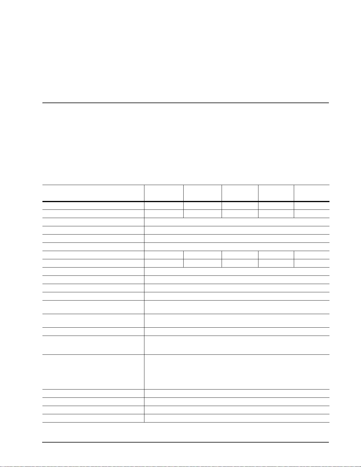
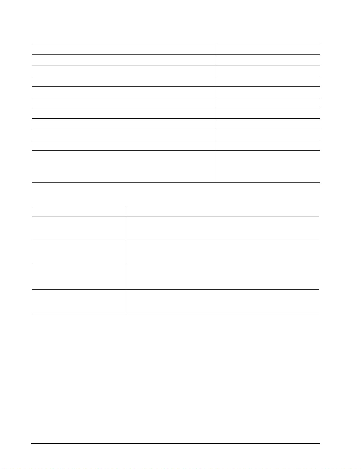
2.1 Specification summary table
The specificatio ns lis ted in th is table ar e for quick reference. F or details on specification me as ur eme nt o r de finition, see the appropriate section of this manual.
Drive specification
Formatted Gbytes (512 bytes/sector) 160 120 80 60 40
Guaranteed sectors 312,581,808 234,441,648 156,301,488 117,231,408 78,165,360
Bytes per sector 512
Default sectors per track 63
Default read/write heads 16
Default cylinders 16,383
Physical read/write heads 4 3 2 2 1
Discs 2 2 1 1 1
Recording density, BPI (bits/inch max) 595,000
Track density , TPI (tracks/inch max) 94,600
Areal density, (Mbits/inch2 max) 56.3
Spindle speed (RPM) 7,200
Internal data transfer rate OD
(Mbytes/sec max)
Sustained data transfer rate OD
(Mbytes/sec)
I/O data-transfer rate (Mbytes/sec max) 100
ATA data-transfer modes supported PIO modes 0–4
Cache buffer
ST3160021A, ST3120022A, ST380011A,
ST360014A, and ST340014A
ST3160023A, ST3120026A, and
ST380013A
Height (mm max) 26.035 mm (1.028 inches)
Width (mm max ) 101.6 mm (4.000 inches)
Length (mm max) 146.99 mm (5.787 inches)
Weight (typical) 635 grams (1.4 lb)
ST3160021A
ST3160023A
85.4
58
Multiword DMA modes 0–2
Ultra DMA modes 0–5
2 Mbytes (2,048 kbytes)
8 Mbytes (8,192 kbytes)
ST3120022A
ST3120026A
ST380011A
ST380013A ST360014A ST340014A
Barracuda 7200.7 Product Manual, Rev. E 3
Page 14
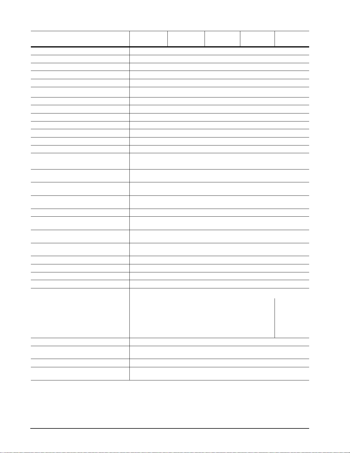
ST3160021A
Drive specification
Average latency (msec) 4.16
Power-on to ready (sec typical) 10 sec
Standby to ready (sec typical) 10 sec
Startup current (typical) 12V (peak) 2.8 amps
Track-to-track seek time (msec typical) <1.0 (read), <1.2 (write)
Average seek time (msec typical)
Average seek, read (msec typical) 8.5
Average seek, write (msec typical) 9.5
Seek power (typical) 12.5 watts
Read/write power (typical) 12.0 watts
Idle mode (typical) 7.5 watts
Standby mode (typical) 0.9 watts
Sleep mode (typical) 0.9 watts
Voltage tolerance (including noise)
Ambient temperature 0° to 60°C (operating)
Temperature gradient (°C per hour max) 20°C (operating)
Relative humidity 5% to 90% (operating)
Relative humidity gradient 30% per hour max
Wet bulb temperature (°C max) 33 (operating)
Altitude, operating –60.96 m to 3,048 m
Altitude, nonoperating (below mean sea
level, max)
Shock, operating (Gs max at 2 msec) 63
Shock, nonoperating (Gs max at 2 msec) 350 Gs
Vibration, operating 1.0 G (0 to peak, 5–350 Hz)
Vibration, nonoperating 5.0 Gs (0 to peak, 22–350 Hz)
Drive acoustics Sound power (bels)
ST3160023A
8.5
5V ± 5%
12V ± 10%
–40° to 70°C (nonoperating)
30°C (nonoperating)
5% to 95% (nonoperating)
40 (nonoperating)
(–200 ft to 10,000+ ft)
–60.96 m to 12,192 m
(–200 ft to 40,000+ ft)
ST3120022A
ST3120026A
ST380011A
ST380013A ST360014A ST340014A
Idle* <2.5 (typical)
Quiet seek 2.8 (typical)
Performance seek 3.4 (typical)
Nonrecoverable read errors 1 per 10
Mean time between failures
(power-on hours)
Service life 5 Years
Contact start-stop cycles
(25°C, 40% rel. humidity)
*During periods of drive idle, some o ffline activity may occur according to the S. M.A.R.T. specification, which may increase acoust ic and
power to operational levels.
2.7 (max)
3.0 (max)
3.7 (max)
14
600,000
50,000
bits read
<2.2 (typ)
2.4 (max)
2.5 (typ)
2.7 (max)
3.1 (typ)
3.5 (max)
4 Barracuda 7200.7 Product Manual, Rev. E
Page 15
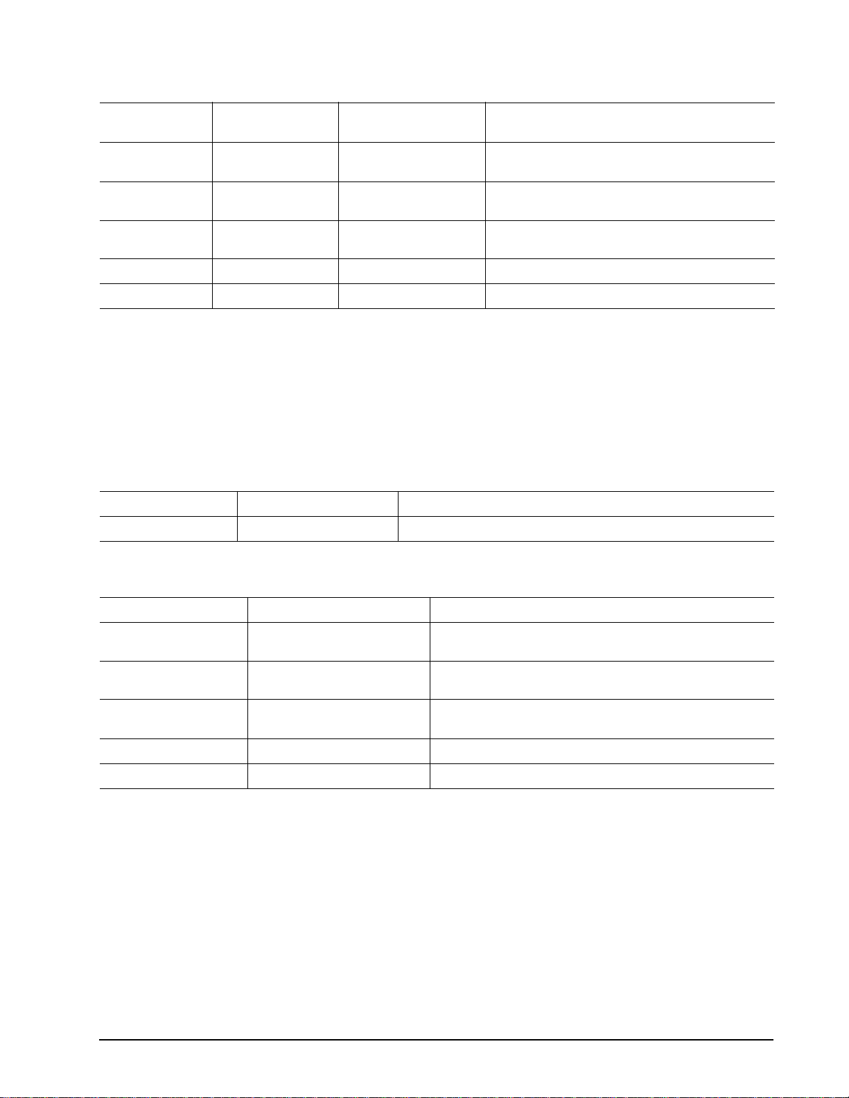
2.2 Formatted capacity
Model
ST3160021A
ST3160023A
ST3120022A
ST3120026A
ST380011A
ST380013A
ST360014A 60 Gbytes 117,231,408 512
ST340014A 40 Gbytes 78,165,360 512
Formatted
capacity
160 Gbytes 312,581,808 512
120 Gbytes 234,441,648 512
80 Gbytes 156,301,488 512
Guaranteed
sectors
Bytes per sector
2.2.1 LBA mode
When addressing these d rives in LBA mode, all bl ocks (sectors) are c onsecutively numbered fr om 0 to n–1,
where n is the number of guaranteed sectors as defined above.
See Section 4. 1.2, "Id enti fy Dev i ce co mma nd" ( wor ds 60 -6 1 a nd 1 00- 10 3) for a ddi tio nal in for ma tio n ab out 48bit addressing support of drives with capacities over 137 Gbytes.
2.3 Default logical geometry
Cylinders Read/write heads Sectors per track
16,383 16 63
2.4 Physical organization
Model Read/write heads Number of discs
ST3160021A
ST3160023A
ST3120022A
ST3120026A
ST380011A
ST380013A
ST360014A 2 1
ST340014A 1 1
4 2
3 2
2 1
Barracuda 7200.7 Product Manual, Rev. E 5
Page 16
2.5 Recording and interface technology
Interface ATA
Recording method 16/17 EPRML
Recording density BPI (bits/inch max) 595,000
Track density TPI (tracks/inch max) 94,600
Areal density (Mbits/inch2 max) 56.3
Spindle speed (RPM) (± 0.2%) 7,200
Internal data-transfer rate OD (Mbytes/sec max) 85.4
Sustained data transfer rate OD (Mbytes/sec max) 58
I/O data-transfer rate (Mbytes/sec max) 100 (Ultra DMA mode 5)
Interleave 1:1
Cache buffer
ST3160021A, ST3120022A, ST380011A, ST360014A, and ST340014A 2 Mbytes (2,048 kbytes)
ST3160023A, ST3120026A, and ST380013A 8 Mbytes (8,192 kbytes)
2.6 Physical characteristics
Drive specification
Maximum height
Maximum width
Maximum lengt h
Typic al we ig ht
(mm)
(inches)
(mm)
(inches)
(mm)
(inches)
(grams)
(pounds)
26.035
1.028
101.6
4.00
146.99
5.787
635
1.4
6 Barracuda 7200.7 Product Manual, Rev. E
Page 17

2.7 Seek time
Seek measurements are taken with nominal power at 25°C ambient temperature. All times are measured using
drive diagnostics. The specifications in the table below are defined as follows:
• Track-to-track seek time is an average of all possible single-track seeks in both directions.
• Average seek time is a true statistical rand om average of at least 5,000 measure ments of seeks between
random tracks, less overhead.
T ypic al see k times (mse c) Read Write
Track-to-track <1.0 <1.2
Average 8.5 9.5
Average latency: 4.16 4.16
Note. These drives are designed to consistently meet the seek times represented in this manual. Physical seeks,
regardless of mode (such as track-to-track and average), are expected to meet or exceed the noted values.
However, due to the manner in which these drives are formatted, benchmark tests that include command
overhead or measure logical seeks may produce results that vary from these specifications.
2.8 Start/stop times
Power-on to Ready (sec) 10 (max)
Standby to Ready (sec) 10 (max)
Ready to spindle stop (sec) 20 (max)
2.9 Power specifications
The drive receives DC power (+5V or +12V) through a four-pin standard drive power connector.
Barracuda 7200.7 Product Manual, Rev. E 7
Page 18

2.9.1 Power consumption
Power requirements for the drives are listed in the table on page 8. Typical power measurements are based on
an average of drives tested, under nomi nal conditions, using 5.0 V and 12.0V input vo ltage at 25°C ambient
temperature.
• Spinup power
Spinup power is measured from the time of power-on to the time that the drive spindle reaches operating speed.
• Seek mode
During seek mode, the read/write actuator arm moves toward a specific position on the disc surface and does
not execute a read or write operatio n. Serv o electr onics ar e active. S eek mode power repres ents the worstcase power consump tion, using only random se eks with read or write laten cy time. This mode is not typic al
and is provided for worst-case information.
• Read/write power and current
Read/write power is mea sured with the he ads on track, base d on a 16-secto r write followed by a 32-msec
delay, then a 16-sector read followed by a 32-msec delay.
• Operating power and current
Operating power is mea sure d using 40 percent random seek s, 40 p er cent r ead /wr ite mod e ( 1 wri te fo r e ac h
10 reads) and 20 percent drive idle mode.
• Idle mode power
Idle mode power is measur ed wi th th e driv e up to s pee d, wi th ser vo ele ctron ics act ive and with the heads in
a random track location.
• Standby mode
During Standby mode, the driv e accepts commands, but the dr ive is not spinning, and the ser vo and read/
write electronics are in power-down mode.
Power dissipation (watts)
Example: ST3160021A, 2-disc
Spinup — — 2.8 (peak)
Idle 7.5 0.482 0.424
Idle* (with offline activity) 9.3 0.587 0.530
Operating 40% r/w, 40% seek, 20% inop. 12.0 0.638 0.739
Seeking 12.5 0.412 0.870
Standby 0.900 0.144 0.015
Sleep 0.900 0.144 0.015
*During periods of drive idle, some o ffline activity may occur according to the S. M.A.R.T. specification, which may increase acoust ic and
power to operational levels.
Average
(watts, 25° C)
5V typ
amps
12V typ
amps
8 Barracuda 7200.7 Product Manual, Rev. E
Page 19
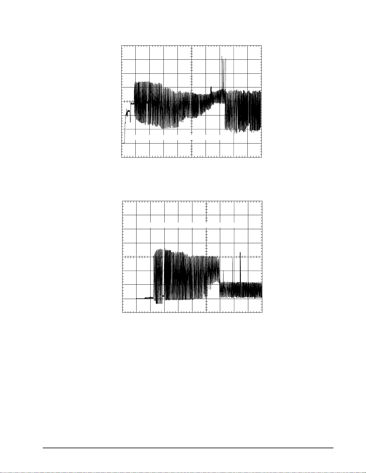
2.9.1.1 T ypical current profile
A
A
1.2
1.0
0.8
mps
0.6
0.4
0.2
0.0
+5 Volt Current during spindle start — Typical Amperes
1234 56789
Seconds
Figure 1. Typical 5V startup and operation current profile
3.0
2.5
2.0
mps
1.5
1.0
0.5
0.0
+12 Volt Current during spindle start — Typical Amperes
012345678
Seconds
Figure 1. Typical 12V startup and operation current profile
Barracuda 7200.7 Product Manual, Rev. E 9
Page 20

2.9.2 Conducted noise
Input noise ripple is mea su red at the ho st system power supply acro ss an equ iv al ent 80 -o hm res ist ive load on
the +12 volt line or an equivalent 15-ohm resistive load on the +5 volt line.
• Using 12-volt power, the drive is expected to operate with a maximum of 120 mV peak-to-peak square-wave
injected noise at up to 10 MHz.
• Using 5-volt power, the drive is expect ed to ope rate wi th a max imum of 10 0 mV pe ak-t o-peak s quare- wave
injected noise at up to 10 MHz.
Note. Equivalent resis tance is calculated by div iding the nominal voltage by the typical RMS read/write
current.
2.9.3 Voltage tolerance
Voltage tolerance (including noise):
5V ± 5%
12V ± 10%
2.9.4 Power-management modes
The drive provides programmab le power mana gement to provide grea ter energy efficiency. In most systems,
you can control power management through the system setup program. The drive features the following
power-management modes :
Power mode Heads Spindle Buffer
Active Tracking Rotating Enabled
Idle Tracking Rotating Enabled
Standby Parked Stopped Enabled
Sleep Parked Stopped Disabled
• Active mode
The drive is in Active mode during the read/write and seek operations.
• Idle mode
The buffer remains en abled, and the drive a ccepts a ll comm ands and re turns to Ac tive mode any time disc
access is necessary.
• Standby mode
The drive enters Standby mode when the host sends a Standby Immediate command. If the host has set the
standby timer, the dri ve can also enter Stand by mode automaticall y after the drive has be en inactive for a
specifiable length of time. The standby timer delay is established using a Standby or Idle command. In Standby
mode, the d rive buffer is enabled, the heads ar e parked and the spindle is at rest. T he drive accepts all
commands and returns to Active mode any time disc access is necessary.
• Sleep mode
The drive enters Sleep mode after receiving a Sleep command from the host. In Sleep mode, the drive buffer
is disabled, the he ads are p arke d and the spind le is at rest. T he dr ive leav es Slee p mo de after it rece ives a
Hard Reset or Soft Reset from the host. After receiving a reset, the drive exits Sleep mode and enters Standby
mode with all current translation parameters intact.
• Idle and Standby timers
Each time the drive perfo rms an Active function (read, wr ite or seek), the standby time r is reinitialized and
begins counting down from its specified delay times to zero. If the standby timer reaches zero before any drive
10 Barracuda 7200.7 Product Manual, Rev. E
Page 21

activity is required, the driv e makes a transi tion to Standb y mode. In both Idle and Standby mode, the d rive
accepts all commands and returns to Active mode when disc access is necessary.
2.10 Environmental specifications
2.10.1 Ambient temperature
Ambient temperature is defined as the temperature of the environment immediately surrounding the drive.
Actual drive case temperature should not exceed
Above 1,000 feet (305 meters), the ma ximum temperature is derated linearly to 112°F (44°C) at 10,000 feet
(3,048 meters).
Operating: 0° to 60°C (32° to 140°F)
Nonoperating: –40° to 70°C (–40° to 158°F)
2.10.2 Te mperature gradient
Operating: 20°C per hour (68°F per hour max), without condensation
Nonoperating: 30°C per hour (86°F per hour max)
2.10.3 Humidity
69°C (156°F) within the operating ambient conditions.
2.10.3.1 Relative humidity
Operating: 5% to 90% noncondensing (30% per hour max)
Nonoperating: 5% to 95% noncondensing (30% per hour max)
2.10.3.2 Wet bulb temperature
Operating: 33°C (91.4°F max)
Nonoperating: 40.0°C (104°F max)
2.10.4 Altitude
Operating: –60.96 m to 3,048 m (–200 ft to 10,000+ ft)
Nonoperating: –60.96 m to 12,192 m (–200 ft to 40,000+ ft)
Barracuda 7200.7 Product Manual, Rev. E 11
Page 22

2.10.5 Shock
All shock specificat ions assume that the drive is mou nted securely with the input s hock applied at the drive
mounting screws. Shock may be applied in the X, Y or Z axis.
2.10.5.1 Operating shock
These drives compl y with the performance level s specified in this docu ment when subjected to a ma ximum
operating shock of 6 3 Gs based on half-sine sh ock pulses of 2 msec. S hocks should not be repeat ed more
than two times per second.
2.10.5.2 Nonoperating shock
The nonoperating s hock l evel that th e driv e can expe rience withou t incur ring ph ysic al d amage or degr adatio n
in performance when subsequently put into operation is 350 Gs based on a nonrepetitive half-sine shock pulse
of 2 msec duration.
2.10.6 Vibration
All vibration spec ifications assume that the drive is moun ted securely with the input vibration applied at the
drive mounting screws. Vibration may be applied in the X, Y or Z axis.
2.10.6.1 Operating vibration
The following table lists the maximum vibration lev els that the dri ve may expe rience while meet ing the perfor mance standards specified in this document.
5–350 Hz 1.0 G acceleration (zero to peak)
2.10.6.2 Nonoperating vibration
The following table l ists the maximum no noperating vibr ation that the drive may expe rience without incurring
physical damage or degradation in performance when subsequently put into operation.
5–22 Hz 1.0-inch displacement (zero to peak)
22–350 Hz 5.0 Gs acceleration (zero to peak)
2.11 Acoustics
Drive acoustics a re measured as overall A -weighted acoustic sound p ower levels (no pure to nes). All measurements are consistent with ISO document 7779. S ound power measureme nts are taken under essentially
free-field conditions over a reflecting plane. For all tests, the drive is oriented with the cover facing upward.
Note. For seek mode tests, the drive is placed in seek mode only. The number of seeks per second is defined
by the following equation:
(Number of seeks per second = 0.4 / (average latency + average access time)
12 Barracuda 7200.7 Product Manual, Rev. E
Page 23

Table 1: Fluid Dynamic Bearing (FDB) motor acoustics
Acoustic mode
Models Idle* Quiet seek Performance seek
ST3160021A
ST3160023A
ST3120022A
ST3120026A
ST380011A
ST380013A
ST360014A
ST340014A <2.2 bels (typ)
*During periods of drive idle, some o ffline activity may occur according to th e S.M.A.R.T. specification, which may increase ac oustic and
power to operational levels.
<2.5 bels (typ)
2.7 bels (max)
2.4 bels (max)
2.8 bels (typ)
3.0 bels (max)
2.5 bels (typ)
2.7 bels (max)
3.4 bels (typ)
3.7 bels (max)
3.1 bels (typ)
3.5 bels (max)
2.12 Electromagnetic immunity
When properly installed in a representative host system, the drive operates without err ors or degradation in
performance when subjected to the radio frequency (RF) environments defined in the following table:
Test Description
Electrostatic discharge Contact, HCP, VCP: ± 4 kV; Air:
± 8 kV
Radiated RF immunity 80 to 1,000 MHz, 3 V/m,
80% AM with 1 kHz sine
900 MHz, 3 V/m, 50% pulse
modulation @ 200 Hz
Performance
level
B EN 61000-4-2: 95
A EN 61000-4-3: 96
Reference
standard
ENV 50204: 95
Electrical fast transient ± 1 kV on AC mains, ± 0.5 kV on
external I/O
Surge immunity ± 1 kV differential, ± 2 kV com-
mon, AC mains
Conducted RF immunity 150 kHz to 80 MHz, 3 Vrms,
80% AM with 1 kHz sine
Voltage dips,interrupts 0% open, 5 seconds
0% short, 5 seconds
40%, 0.10 seconds
70%, 0.01 seconds
B EN 61000-4-4: 95
B EN 61000-4-5: 95
A EN 61000-4-6: 97
C
C
C
B
EN 61000-4-11: 94
2.13 Reliability
Nonrecoverable read errors 1 per 1014 bits read, max.
Mean time between failures 600,000 power-on hours (nominal power, 25°C ambient temperature)
Contact start-stop cycles 50,000 cycles
(at nominal voltage and temperature, with 60 cycles per hour and a 50% duty cycle)
Service Life 5 Years
Preventive maintenance None required
Barracuda 7200.7 Product Manual, Rev. E 13
Page 24

2.14 Agency certification
2.14.1 Safety certification
The drives are recogni ze d in ac co rd anc e with UL 1950 and CSA C22.2 (950 ) and m eet all applicable sections
of IEC950 and EN 60950 as tested by TUV North America.
2.14.2 Electromagnetic compatibility
Hard drives that display the CE mark comply with the European Union (EU) requirements specified in the Electromagnetic Compatibility Di rective (89/336/EE C). Testing is performed to the lev els specified by the pr oduct
standards for Information Technology Equipment (ITE). Emission levels are defined by EN 55022, Class B and
the immunity levels are defined by EN 55024.
Seagate uses an independent laboratory to confirm compliance with the EC directives specified in the previous
paragraph. Drives are tested in representative end-user systems. Although CE-marked Seagate drives comply
with the directives wh en used in the test systems, we cannot guarantee th at all systems will comply wit h the
directives. The drive is designed for operation inside a properly designed enclosure, with properly shielded I/O
cable (if necessary) and termi nators on all unu sed I/O ports. Compute r manufacture rs and system inte grators
should confirm EMC compliance and provide CE marking for their products.
Korean RRL
If these drives have the Korea M inistry of Information a nd Comm unication ( MIC) logo , they co mply with paragraph 1 of Article 11 of the Electromagnetic Compatibili ty control Regulation and meet the Electr omagnetic
Compatibility (EMC) Framework req ui remen ts of the Radio Res earc h Labo rator y (RRL) Minis try of Infor ma tio n
and Communication Republic of Korea.
These drives have been tested and comply with the Electromagnetic Interference/Electromagnetic Susceptibility (EMI/EMS) for Class B products. Drives are tested in a representative, end-user system by a Korean-recognized lab.
• EUT name (model numbers): ST3160023A, ST3160021A, ST3120026A, ST3120022A, ST380013A,
ST380011A, ST360014A, and ST340014A.
• Certificate numbers: ST3160023A E-H011-03-0089
ST3160021A E-H011-03-0085
ST3120026A E-H011-03-0086
ST3120022A E-H011-03-0087
ST380011A E-H011-03-0084
ST340014A E-H011-03-0083
ST380013A E-H011-03-0088
ST360014A E-H011-03-0088
• Trade name or applicant: Seagate Technology
• Manufacturing date: January 2003
• Manufacturer/nationality: Singapore and China
Australian C-Tick (N176)
If these models h ave the C-Tick marki ng, th ey com ply wi th the Aus tralia/N ew Z ealand Standard AS/NZS 3548
1995 and meet the Electromagnetic Compatibility (EMC) Framework requirements of the Australian Communi
cation Authority (ACA).
-
14 Barracuda 7200.7 Product Manual, Rev. E
Page 25

2.14.3 FCC verification
These drives are intended to be contained solely within a personal computer or similar enclosure (not attached
as an external device). As such, each drive is considered to be a subassembly even when it is individually mar
keted to the customer. As a subassembly, no Federal Communications Commission verification or ce rt ifica tion
of the device is required.
Seagate Technology LLC has tested this device in enclosures as described above to ensure that the total
assembly (enclosure, dis c drive, motherboard, power supply, etc.) does comply with the limits for a Class B
computing device , pursuant to S ubpart
likely to result in interference to radio and television reception.
Radio and television interference. This equipment generates and uses radio frequency energy and if not
installed and used in strict accordance with th e manufacturer ’s instructions, may cause i nterference to radio
and television reception.
This equipment is designed to provide reasonable protection against such interference in a residential installation. However, there is no guarantee that interference will not occur in a particular installation. If this equipment
does cause interfer ence to radio or te levision, whic h can be determi ned by turning t he equipment on and off,
you are encouraged to try one or more of the following corrective measures:
• Reorient the receiving antenna.
• Move the device to one side or the other of the radio or TV.
• Move the device farther away from the radio or TV.
• Plug the computer into a different outlet so that the receiver and computer are on different branch outlets.
J, Part 15 of the FCC rule s. Operatio n with noncertifi ed assemblies is
-
If necessary, you should consult your deal er or an experienced radio /television technician for additional suggestions. You may find helpful the following booklet prepared by the Feder al Communications Commission:
How to Identify and Resolve Radio-Television Interference Problems. This booklet is available from the Super
intendent of Documents, U.S. Government Printi ng Office, Washington, DC 20402. Refer to p ublication number 004-000-00345-4.
-
Barracuda 7200.7 Product Manual, Rev. E 15
Page 26

16 Barracuda 7200.7 Product Manual, Rev. E
Page 27

3.0 Configuring and mounting the drive
This section contains the specifications and instructions for configuring and mounting the drive.
3.1 Handling and static discharge precautions
After unpacking, and before ins tallation, the dr ive may be ex posed to pote ntial handli ng and electrostatic discharge (ESD) hazards. Observe the following standard handling and static-discharge precautions:
Caution:
• The SeaShell™ replaces electrostatic discharge (ESD) bags. The SeaShell package is a shock-ribbed,
transparent clamshell enclosure that limits a drive’s exposu re to ESD and also protects agains t external
shocks and st resses. The design permits attaching cables, software loading and labe l/barcode scanning
without removing the driv e fr om the SeaSh ell. Th is mi nimi zes handli ng dam age. K eep the drive in the Sea
Shell package until you are ready for installation.
• Before handling the drive, put on a grounded wrist strap, or ground yourself frequently by touching the metal
chassis of a com puter that is plugge d into a grounded outl et. Wear a grounded wris t strap throughout th e
entire installation procedure.
• Handle the drive by its edges or frame only.
• The drive is extremely fragile—handle it with care. Do not press down on the drive top cover.
• Always rest the drive on a padded, antistatic surface until you mount it in the computer.
• Do not touch the connector pins or the printed circuit board.
• Do not remove the factory-installed labels from the drive or cover them with additional labels. Removal voids
the warranty. Some factory-installed labels co ntain in for ma tio n nee ded to s er vice the d ri ve. Other l abe ls are
used to seal out dirt and contamination.
-
Barracuda 7200.7 Product Manual, Rev. E 17
Page 28

3.2 Breather filter hole precautions
This section contains information regarding the precautions which should be taken regarding the breather filter
hole in Seagate hard d isc drives. Prop er precautions should be taken to en sure full functio nality and preven t
possible damage to the drive.
Breather Hole
Do not cover
or seal.
Figure 1. Breather filter hole location
Caution: Do not cover, seal, or insert any object into this h ole.
This hole has two purposes:
• To allow condensation inside the hard disc to escape
• To allow air pressure inside the hard disc to equalize with ambient pressure
Note. If this hole is covered, sealed, or penetrated by any object, the drive reliability may be compromised
and could lead to permanent damage—doing so voids the warranty.
18 Barracuda 7200.7 Product Manual, Rev. E
Page 29

3.3 Jumper settings
rd
3.3.1 Master/slave configuration
The options jumper b lock shown in Figure 1 is used to configure the drive for operatio n. It is the 8-pin dual
header between the in terface connec tor and the power connector. Use the following settings to con figure the
drive as a master or a slave.
Master or single drive. The drive is configured at the factor y for a master or single-drive operation with a
jumper set on pins 7 and 8.
Drive as slave. Remove all jumpers.
Drive as master with a non-ATA-compatible slave.
Use this jumper setting only if the drive does not work as a master with no jumpers installed.
Options jumper block
Master or single drive
Drive is slave
Master with non ATAcompatible slave
Cable select
Limit drive capacity
to 32 Gbytes
1753
684
2
Figure 1. Master/slave jumper settings
Circuit Boa
3.3.2 Cable-select option
Computers that use cable select det ermine the master and slave drives by selecting or dese lecting pin 28,
CSEL, on the interface bus. Master and slav e dr ives are det ermi ned by their phys ical pos i tio n on the cab le. To
enable cable selec t, set a jumper on pins 5 and 6 as shown i n Figure
1. Refer to your computer manual to
determine whether your computer supports this option.
3.3.3 Alternate capacity jumper
Some older comput ers may “hang ” at startup if their B IOS de tects a disc drive with a ca pacity gre ater than 3 2
Gbytes. This limits the drive’s capacity to 32 Gbytes when the alternate capacity jumper is used. To access the
full capacity of the drive, you can:
• Update the BIOS
• Use third-party software such as DiscWizard™ or Disk Manager
• Use a third-party host adapter
For drives with capacitie s greater than 32 Gbytes, the al ternate capacity jumper changes the total available
LBA sectors to 32 Gb ytes to solve is sues with some BI OS during power on . The ATA Set Features subcom
mand “F1H Report Full Capacity Availab le” causes Identif y Data words 60 and 61 to rep ort the full capacity.
See Section 4.1.3 on page 30 for more details on the Set Features command.
-
Barracuda 7200.7 Product Manual, Rev. E 19
Page 30

Windows XP, Windows Me, Windows 98 or newer versions are needed to support drives with capacities
r
e
M
S
greater than 32 Gbytes.
3.3.4 Ultra ATA/100 cable
An 80-conductor 40-pin cable is required to run Ultra DMA mode 3, mode 4 and mode 5. This cable uses evennumbered conductors connected to the ground pins to improve signal integrity.
Note. If you are using a 40-pin, 80-conducto
cable, attach the blue connector to the
aster
lave
Pin 1
Computer
Motherboard
motherboard, the black connector to th
master drive, and the gray connector
to the slave.
Figure 1. Ultra ATA cable connectors
Note. The drive supports both host and drive cable detection. The host detects the 80-conductor cable by
sampling pin 34, CBLID–, on the interface bus . The drive detec ts the 80-conduc tor cable by sens
ing a capacitor at the host side thr ough the CBLID– signal. The result is repor ted in a Fast Rise
Detected bit (bit 13 of word 93 in the Identify drive parameter block).
3.4 Drive mounting
You can mount the driv e in any o rientation u sing four s crews in the side -mountin g holes or four screws i n the
bottom-mounting holes. See Figure
tions when mounting the drive:
• Allow a minimum clearance of 0.030 inches (0.76 mm) around the entire perimeter of the drive for cooling.
• Use only 6-32 UNC mounting screws.
• Do not overtighten the mounting screws (maximum torque: 6 inch-lb).
• Do not use a drive interface cable that is more than 18 inches long.
1 for drive mounting dimensions. Follow these important mounting precau-
20 Barracuda 7200.7 Product Manual, Rev. E
Page 31
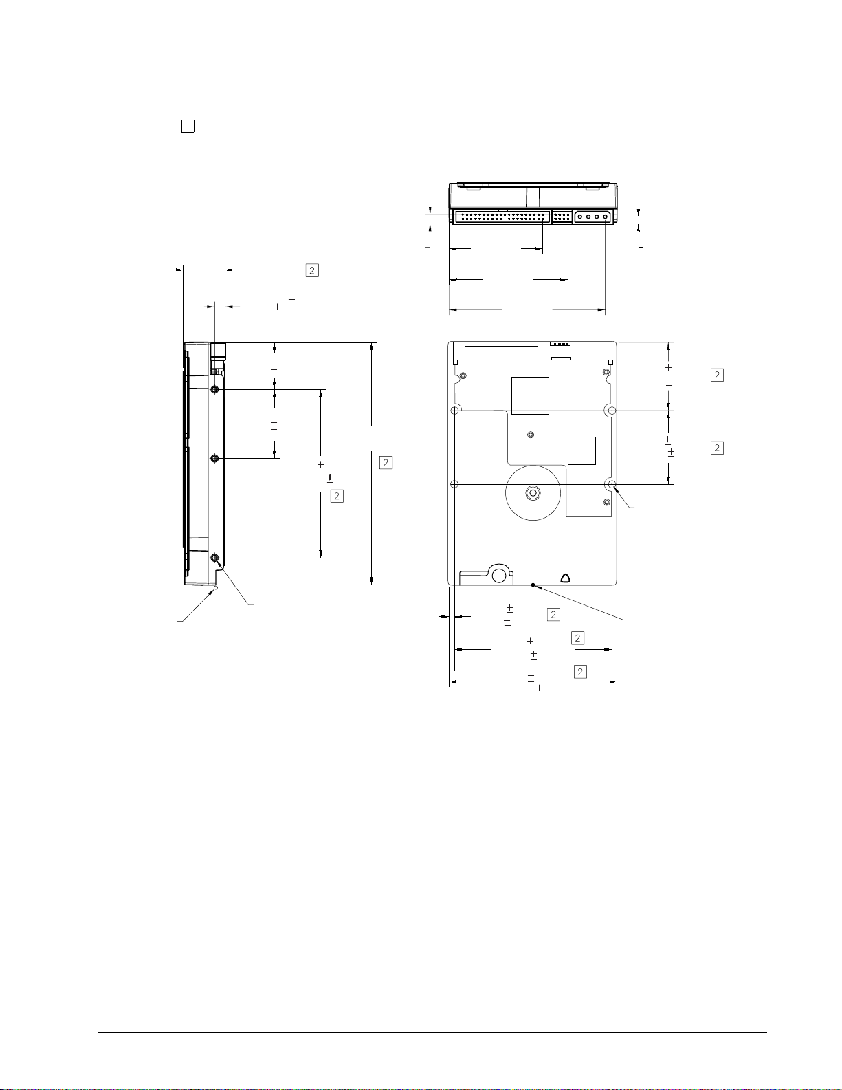
Notes:
1. Dimensions are shown in inches (mm).
R
c
m
er
2 Dimensions per SFF-8301 specification.
ecommended
ase temperature
easurement location
1.028 max
(26.11)
3 x 0.25 0.015
(6.35 0.037)
both sides
1.122 0.02
(28.5 0.51)
1.638 0.01
(41.61 0.25)
3 x 6-32 UNC-2B
0.150 (3.81) max. fastener
penetration both sides. 3 threads
minimum engagement.
2
5.787 max
(146.99)
4.0 0.01
(101.60 0.25)
0.228
(5.79)
2.23
(56.56)
2.83
(71.80)
3.71
(94.35)
0.125 0.01
(3.18 0.25)
3.75 0.01
(95.25 0.25)
4.0 0.01
(101.60 0.25)
0.178
(4.27)
1.625 0.02
(41.28 0.51)
1.75 0.01
(44.45 0.25)
4 x 6-32 UNC-2B
0.150 (3.81) max. fasten
penetration. 3 threads
minimum engagement.
Recommended
case temperature
measurement location
Figure 1. Mounting dimensio ns—to p, side and end view
Barracuda 7200.7 Product Manual, Rev. E 21
Page 32

22 Barracuda 7200.7 Product Manual, Rev. E
Page 33

4.0 ATA interface
These drives use t he industry-standard ATA task file interface that s upports 16-bit data transfer s. It supports
ATA programmed input/output (PIO) modes 0–4; m ultiwor d DMA m odes 0– 2, and Ul tra DMA mod es 0–5. The
drive also supports the use of the IORDY signal to provide reliable high-speed data transfers.
You c an us e a dai sy-ch ain cabl e to co nnect two dri ves to a singl e AT host bus. For detailed inform ation about
the ATA interface, refer to the draft of AT Attachment with Packet Interface Extension (ATA/ATAPI-6), NCITS
T13 1410D, subsequently referred to as the Draft ATA-6 Standard.
4.1 ATA interface signals and connector pins
Figure 1 on page 24 su mmarizes the signals on the ATA interface conne ctor that the drive supports. For a
detailed description of these signals, refer to the Draft ATA-6 Standard.
Barracuda 7200.7 Product Manual, Rev. E 23
Page 34

Drive pin #
.
10
11
12
13
14
15
16
17
18
19
20
21
22
23
24
25
26
27
28
29
30
31
32
33
34
35
36
37
38
39
40
Signal name
–
1
2
3
4
5
6
7
8
9
Reset
Ground
DD7
DD8
DD6
DD9
DD5
DD10
DD4
DD11
DD3
DD12
DD2
DD13
DD1
DD14
DD0
DD15
Ground
(removed)
DMARQ
Ground
DIOW–
STOP
Ground
DIOR
–
HDMARDY
HSTROBE
Ground
IORDY
DDMARDY–
DSTROBE
CSEL
–
DMACK
Ground
INTRQ
–
IOCS16
DA1
–
PDIAG
CBLID–
DA0
DA2
–
CS0
–
CS1
–
DASP
Ground
–
Host pin # and signal description
1
Hardware Reset
2
Ground
3
Host Data Bus Bit 7
4
Host Data Bus Bit 8
5
Host Data Bus Bit 6
6
Host Data Bus Bit 9
7
Host Data Bus Bit 5
8
Host Data Bus Bit 10
9
Host Data Bus Bit 4
10
Host Data Bus Bit 11
11
Host Data Bus Bit 3
12
Host Data Bus Bit 12
13
Host Data Bus Bit 2
14
Host Data Bus Bit 13
15
Host Data Bus Bit 1
16
Host Data Bus Bit 14
17
Host Data Bus Bit 0
18
Device Data (15:0)
19
Ground
(No Pin)
20
21
DMA Request
22
Ground
23
Device I/O Write:
Stop Ultra DMA Burst
24
Ground
25
Device I/O Read:
Host Ultra DMA Ready:
Host Ultra DMA Data Strobe
26
Ground
27
I/O Channel Ready
Device Ultra DMA Ready
Device Ulta DMA Data Strobe
28
Cable Select
29
DMA Acknowledge
30
Ground
31
Device Interrupt
32
Reserved
33
Host Address Bus Bit 1
34
Passed Diagnostics
Cable Assembly Type Identifier
35
Device Address (2:0)
36
Device Address (2:0)
37
Chip Select (1:0)
38
Chip Select (1:0)
39
Drive Active/Slave Present
40
Ground
Pins 28, 34 and 39 are used for master-slave communication (details shown below)
28
34
39
Drive 0 (master)Drive 1 (slave)
28
34
39
CSEL
PDIAG
DASP–
–
Host
28
34
39
Figure 1. I/O pins and supported ATA signals
24 Barracuda 7200.7 Product Manual, Rev. E
Page 35

4.1.1 Supported ATA commands
The following table lists ATA-standard com man ds th at the driv e s upp orts. For a detaile d des cri pti on of the ATA
commands, refer to the Draft ATA-6 Standard.
See “S.M.A.R.T. commands” on page 31 for details and sub-
commands used in the S.M.A.R.T. implementation.
Command name Command code (in hex)
ATA-standard commands
Download Microcode 92
Execute Device Diagnostics 90
Flush Cache E7
Flush Cache Extended EA
Identify Device EC
Initialize Device Parameters 91
Read Buffer E4
Read DMA C8
Read DMA Extended 25
Read Multiple C4
Read Multiple Extended 29
Read Native Max Address F8
Read Native Max Address Extended 27
Read Sectors 20
Read Sectors Extended 24
Read Verify Sectors 40
Read Verify Sectors Extended 42
Seek 70
Set Features EF
Set Max F9
Note: Individual Set Max commands are identified b y the value
placed in the Set Max Features
register as defined to the right.
Set Multiple Mode C6
S.M.A.R.T. B0
Write Buffer E8
Write DMA CA
Write DMA Extended 35
Write Multiple C5
Write Multiple Extended 39
Write Sectors 30
H
H
H
H
H
H
H
H, C9H
H
H
H
H
H
H, 21H
H
H, 41H
H
H
H
H
H
H
H
H, CBH
H
H
H
H, 31H
Address:
Password:
Lock:
Unlock:
Freeze Lock:
00
01
02
03
04
H
H
H
H
H
Barracuda 7200.7 Product Manual, Rev. E 25
Page 36

Command name Command code (in hex)
Write Sectors Extended 34
H
ATA-standard power-management commands
Check Power Mode 98H or E5
Idle 97H or E3
Idle Immediate 95H or E1
Sleep 99H or E6
Standby 96H or E2
Sta ndb y Imm ed iate 94H or E0
ATA-standard security commands
Security Set Password F1
Security Unlock F2
Security Erase Prepare F3
Security Erase Unit F4
Security Freeze Lock F5
Security Disable Password F6
H
H
H
H
H
H
H
H
H
H
H
H
26 Barracuda 7200.7 Product Manual, Rev. E
Page 37

4.1.2 Identify Device command
The Identify Device command (command code ECH) transfers information about the drive to the host following
power up. The data is o rg ani ze d a s a sin gle 512-byte block of data, who se conte nts ar e sho wn in the table o n
page 27. All reserved bits or words s hould be set to zero. Parameter s listed with an “x” are drive-sp ecific or
vary with the state of the drive.
See Section 2.0 on page 3 for default parameter settings.
The following commands contain drive-specific features that may not be included in the Draft A T A-6 Standard.
Word Description Value
0
Configuration information:
• Bit 15: 0 = ATA; 1 = ATAPI
• Bit 7: removable media
0C5A
• Bit 6: removable controller
• Bit 0: reserved
1 Number of logical cylinders 16,383
2 ATA-reserved 0000
3 Number of logical heads 16
4 Retired 0000
5 Retired 0000
6 Number of logical sectors per logical track: 63 003F
7–9 Retired 0000
10–19 Serial number: (20 ASCII characters, 0000H = none) ASCII
20 Retired 0000
21 Retired 0400
22 Obsolete 0000
23–26 Firmware revision (8 ASCII character string, padded with blanks to end
x.xx
of string)
27–46 Drive model number
(40 ASCII characters, padded with blanks to end of string)
ST3160021A
ST3160023A
ST3120022A
ST3120026A
ST380011A
ST380013A
ST360014A
ST340014A
H
H
H
H
H
H
H
H
H
47 (Bits 7–0) Maximum sectors per interrupt on Read multiple and Write
multiple (16)
48 Reserved 0000
49 Standard Standby timer, IORDY supported and may be disabled 2F00
50 ATA-reserved 0000
51 PIO data-transfer cycle timing mode 0200
52 Retired 0200
53 Words 54–58, 64–70 and 88 are valid 0007
54 Number of current logical cylinders xxxx
55 Number of current logical heads xxxx
8010
H
H
H
H
H
H
H
H
H
Barracuda 7200.7 Product Manual, Rev. E 27
Page 38

Word Description Value
56 Number of current logical sectors per logical track xxxx
57–58 Current capacity in sectors xxxx
59 Number of sectors transferred during a Read Multiple or Write Multiple
xxxx
command
60–61 Total number of user-addressable LBA sectors available
(see Section 2.2 for related information)
*Note: The maximum value allowed in this field is: 0FFFFFFFh
(268,435,455 sectors, 137 Gbytes). Drives with capacities over 137
Gbytes will have 0FFFFFFFh in this fie ld an d the ac tua l num be r of use raddressable LBAs specified in words 100-103. This is required for
drives that support the 48-bit addressing feature.
ST3160021A =0FFFFFFFh*
ST3160023A =0FFFFFFFh*
ST3120022A = 234,441,648
ST3120026A = 234,441,648
ST380011A = 156,301,488
ST380013A = 156,301,488
ST360014A = 117,231,408
ST340014A = 78,165,360
62 Retired 0000
63 Multiword DMA active and modes supported
xx07
(see note following this table)
64 Advanced PIO modes supported (modes 3 and 4 supported) 0003
65 Minimum multiword DMA transfer cycle time per word (120 nsec) 0078
66 Recommended multiword DMA transfer cycle time per word (120 nsec) 0078
67 Minimum PIO cycle time without IORDY flow control (240 nsec) 00F0
68 Minimum PIO cycle time with IORDY flow control (120 nsec) 0078
69–74 ATA-reserved 0000
75 Queue depth 0000
76–79 ATA-reserved 0000
80 Major version number 007E
81 Minor version number 0000
82 Command sets supported 346B
83 Command sets supported 7D01
84 Command sets support extension 4003
85 Command sets enabled 34xx
86 Command sets enabled 3xxx
87 Command sets enable extension 4003
88 Ultra DMA support and current mode
xx3F
(see note following this table)
H
H
H
H
H
H
H
H
H
H
H
H
H
H
H
H
H
H
H
H
H
H
89 Security erase time 0000
90 Enhanced security erase time 0000
92 Master password revision code FFFE
93 Hardware reset value (see description following this table) xxxx
95–99 ATA-reserved 0000
H
H
H
H
H
28 Barracuda 7200.7 Product Manual, Rev. E
Page 39

Word Description Value
100–103 Total number of user-addressable LBA sectors available
(see Section 2.2 for related information)
These words are required for drives that support the 48-bit addressing
feature. Maximum value: 0000FFFFFFFFFFFFh.
ST3160021A = 312,581,808
ST3160023A = 312,581,808
ST3120022A = 234,441,648
ST3120026A = 234,441,648
ST380011A = 156,301,488
ST380013A = 156,301,488
ST360014A = 117,231,408
ST340014A = 78,165,360
104–127 ATA-reserved 0000
128 Security status 0001
129–159 Seagate-reserved xxxx
160–254 ATA-reserved 0000
255 Integrity word xxA5
H
H
H
H
H
Note. Advanced Power Manag ement (APM) and Au tomati c Acoustic Mana gement (AAM) f eatu res are n ot supporte d
Note. See the bit descriptions below for words 63, 88, and 93 of the Identify Drive data:
Description (if bit is set to 1)
Bit Word 63
0 Multiword DMA mode 0 is supported.
1 Multiword DMA mode 1 is supported.
2 Multiword DMA mode 2 is supported.
8 Multiword DMA mode 0 is currently active.
9 Multiword DMA mode 1 is currently active.
10 Multiword DMA mode 2 is currently active.
Bit Word 88
0 Ultra DMA mode 0 is supported.
1 Ultra DMA mode 1 is supported.
2 Ultra DMA mode 2 is supported.
3 Ultra DMA mode 3 is supported.
4 Ultra DMA mode 4 is supported.
8 Ultra DMA mode 0 is currently active.
9 Ultra DMA mode 1 is currently active.
10 Ultra DMA mode 2 is currently active.
11 Ultra DMA mode 3 is currently active.
12 Ultra DMA mode 4 is currently active.
13 Ultra DMA mode 5 is currently active.
Barracuda 7200.7 Product Manual, Rev. E 29
Page 40

Bit Word 93
13 1 = 80-conductor cable detected, CBLID above VIH
0 = 40-conductor cable detected, CBLID below VIL
4.1.3 Set Features command
This command controls the implementation of various features that the drive supports. When the drive receives
this command, it sets BSY, ch ecks the contents of the Features registe r, clears BSY and generates an inter
rupt. If the value in the register does not represent a fea ture that the driv e supports, the comman d is aborted .
Power-on default has the rea d look-ahe ad and write cach ing features enabled . The ac ceptable va lues for th e
Features register are defined as follows:
02
03
55
82
AA
F1
Enable write cache (default).
H
Set transfer mode (based on value in Sector Count register).
H
Sector Count register values:
00
01
08
09
Set PIO mode to default (PIO mode 2).
H
Set PIO mode to default and disable IORDY (PIO mode 2).
H
PIO mode 0
H
PIO mode 1
H
0AHPIO mode 2
0B
0C
20
21
22
40
41
42
43
44
45
Disable read look-ahead (read cache) feature.
H
Disable write cache.
H
Enable read look-ahead (read cache) feature (default).
H
Report full capacity available
H
PIO mode 3
H
PIO mode 4 (default)
H
Multiword DMA mode 0
H
Multiword DMA mode 1
H
Multiword DMA mode 2
H
Ultra DMA mode 0
H
Ultra DMA mode 1
H
Ultra DMA mode 2
H
Ultra DMA mode 3
H
Ultra DMA mode 4
H
Ultra DMA mode 5
H
-
Note. At power-on, or after a hardwar e or software reset, the default v alues of the features are as indi-
cated above.
30 Barracuda 7200.7 Product Manual, Rev. E
Page 41

4.1.4 S.M.A.R.T. commands
S.M.A.R.T. provides near-term failure pred iction for disc drives. When S.M .A.R.T. is ena bled, the drive monitors predetermined driv e attr i bute s tha t are susceptible to d egr ad ati on over t ime . I f s elf -mon ito ri ng de termi nes
that a failure is likely, S.M.A.R.T. makes a status report a vailable to the host. Not a ll failures are predi ctable.
S.M.A.R.T. predictability is limite d to the attributes the dr ive can monitor. For more information on S.M.A.R.T.
commands and implementation, see the Draft ATA-6 Standard.
SeaTool s dia gnostic software a ctiva tes a b uilt-in driv e sel f-test ( DST S. M.A.R .T. command for D4H) that eliminates unnecessary drive returns. The diagnostic software ships with all new drives and is also available at:
http://seatools.seagate.com.
This drive is shipped with S.M.A.R.T. features disabled. Y ou must have a recent BIOS or software package that
supports S.M.A.R.T. to enable this feature. The table below shows the S.M.A.R.T. command codes tha t the
drive uses.
Code in features
register
D0
H
D1
H
D2
H
D3
H
D4
H
D5
H
D6
H
D7
H
D8
H
D9
H
DA
H
S.M.A.R.T. command
S.M.A.R.T. Read Data
Vendor-specific
S.M.A.R.T. Enable/Disable Attribute Autosave
S.M.A.R.T. Save Attribute Values
S.M.A.R.T. Execute Off-line Immediate (runs DST)
S.M.A.R.T. Read Log Sector
S.M.A.R.T. Write Log Sector
Vendor-specific
S.M.A.R.T. Enable Operations
S.M.A.R.T. Disable Operations
S.M.A.R.T. Return Status
Note. If an appropriate code is not writte n to the Features Register, the command is aborted and 0x 04
(abort) is written to the Error register.
Barracuda 7200.7 Product Manual, Rev. E 31
Page 42

32 Barracuda 7200.7 Product Manual, Rev. E
Page 43

5.0 Seagate Technology support services
Online Services
Internet
www.seagate.com for informatio n about Seagate products and servic es. Worldwide support is availab le 24
hours daily by e-mail for your questions.
Presales Support: www.seagate.com/support/email/email_presales.html or DiscPresales@Seagate.com
Technical Support: www.seagate.com/support/email/email_disc_support.html or DiscSupport@Seagate.com
mySeagate
my.seagate.com is the industry’s first Web portal de signed specifically for OEMs and distri butors. It provides
self-service a ccess to cr itical app lications, personaliz ed content and the tool s that allo w our partner s to man
age their Seagate account fun ctions. Submit prici ng requests, order s and returns through a singl e, passwordprotected Web interface—anytime, anywhere in the world.
For support, questions and comments:
E-mail: partner.support@seagate.com
Phone (direct): +1-405-324-4740
Phone (toll-free): 1-877 -347-2444 (US and Canada ), or access a complete list of regi on-specific intern ational
toll-free phone numbers at
reseller.seagate.com
reseller.seagate.com supports Seag ate resellers with produc t information, program benefi ts and sales tools.
You m ay register for customized communications that are not avai lable on the web. These commun ications
contain product launc h, EOL, pr icing, promoti ons and oth er channel- related infor mation. To learn more about
the benefits or to register, go to
my.seagate.com
reseller.seagate.com, any time, from anywhere in the world.
-
reseller.seagate.com partner support
24 hours a day, seven days a week:
By web form: reseller.seagate.com/contact/forms
By phone: Access a complete list of regional phone numbers at reseller.seagate.com/support/
Seagate Online Store
US customers can purchase Seagate disc drives 24 hours daily at www.seagate.com/buy/online/.
Automated Phone Services
SeaFONE® (1-800-SEAGATE) is the Seagate toll-free number (1-800-732-4283) to access our automated
self-help and di rectory a ssistance f or Seagate s upport ser vices. Using a touch- tone phone, you can find ser
vice and suppo rt phone nu mbers, answers to common ly asked que stions, tr oubleshooti ng tips and spec ifications for disc drives 24 hours daily. International callers can reach this service by dialing +1-405-324-4770.
Barracuda 7200.7 Product Manual, Rev. E 33
-
Page 44

Presales, Technical Support and Customer Service
Presales Support
Our Presales Suppo rt staff can help you deter mine which Seagate products are best suited for your specific
application or computer system.
Technical Support
If you need help installing your dr ive, c ons ul t yo ur sy stem's doc ume ntation or contact the deal er's s upp or t services department for assista nce specific to your sy stem. Seagate techn ical support is also av ailable to assist
you online at
configuration information and your drive’s “ST” model number available.
SeaTDD™ (+1-405-324-3655) is a telecommunica tions devi ce fo r the deaf (TD D). You can send question s or
comments 24 hours d aily an d excha nge m essag es wi th a techni cal suppor t spec ialis t dur ing n ormal bus iness
hours for the technical support call center in your region.
Warranty Service
Seagate offers worldwide customer supp ort for Seagate drives. Seagate dis tributors, OEMs and other direct
customers should contact their Seagate service center representative for warranty-related issues. Resellers or
end users of drive products should contact their place of purchase or one of the Seagate warranty service cen
ters for assistance. Have your drive’s “ST” model number and serial number available.
Authorized Service Centers
In some countries outside the US, you can contact an Authorized Service Center for service.
support.seagate.com or through one of ou r tec hnica l suppor t ser vice ce nters . Have your syste m
-
USA/Canada/Latin America Support Services
Presales Support
Call Center Toll-free Direct dial FAX
Americas 1-877-271-3285
Technical Support
Call Center Toll-free Direct dial FAX
Americas 1-800-SEAGATE
Warranty Service
Call Center Toll-free Direct dial FAX / Internet
USA, Mexico and 1-800-468-3472
Latin America
Canada
Memofix
Brazil
MA Centro de Serviços
5
1-800-636-6349 +1-905-660-4936 +1-905-660-4951
5
— +55-21-2509-7267 +55-21-2507-6672
1
+1-405-324-4730
2
+1-405-324-4700
4
+1-405-324-4720
1
3
4
+1-405-324-4704
+1-405-324-4702
+1-405-324-4722
www.memofix.com
www.mainformatica.com.br/produtos.htm
1
Hours of operation are 8:00 A.M. to 11:45 A.M. and 1:00 P.M. to 6:00 P.M., Monday through Friday (Central time)
2
For product-specific phone number
3
Hours of operation are 8:00 A.M. to 8:00 P.M., Monday through Friday (Central time)
4
Hours of operation are 8:30 A.M. to 12:15 P.M. and 1:30 P.M. to 5:30 P.M., Monday through Friday (Central time)
5
Authorized Service Center
34 Barracuda 7200.7 Product Manual, Rev. E
Page 45

European Support Services
For presales and technical support in Europe, dial the toll-free number for your specific country. If your country
is not listed h ere, dial our presales and te chnical support call center at +1-405-324-4714 from 8:00
11:45
A.M. and 1:00 P.M. to 5:00 P.M. (Central Europe time) Monday through Friday. The presales and technical
support call center is located in Oklahoma City, USA.
For European warranty se rvice, dial the tol l-free number for your specific coun try. If your country is not listed
here, dial our European call center at +31-20-316-7222 from 8:30
A.M. to 5:00 P.M. (Central Europe time) Mon-
day through Friday. The warranty service call center is located in Amsterdam, The Netherlands.
Toll-Free Support Numbers
Call Center Presales and Technical Support Warranty Service
Austria 0 800-20 12 90 0 800-20 12 90
Belgium 00 800-47324283 (00 800-4SEAGATE) 00 800-47324289
Denmark 00 800-47324283 00 800-47324289
France 00 800-47324283 00 800-47324289
Germany 00 800-47324283 00 800-47324289
Ireland 00 800-47324283 00 800-47324289
Italy 00 800-47324283 00 800-47324289
Netherlands 00 800-47324283 00 800-47324289
Norway 00 800-47324283 00 800-47324289
Poland 00 800-311 12 38 00 800-311 12 38
Spain 00 800-47324283 00 800-47324289
Sweden 00 800-47324283 00 800-47324289
Switzerland 00 800-47324283 00 800-47324289
Turkey 00 800-31 92 91 40 00 800-31 92 91 40
United Kingdom 00 800-47324283 00 800-47324289
A.M. to
FAX Servi ces—Al l European Countries (toll call)
Warranty Service +31-20-653-3513
Africa/Middle East Support Services
For presales and tec hnical suppo rt in Africa and the Midd le East, dia l our presal es and technic al support c all
center at +1-405-32 4-471 4 from 8:00
day through Friday. The presales and technical support call center is located in Oklahoma City, USA.
For warranty service in Africa and the Middle East, dial our European call center at +31-20-316-7222 from 8:30
A.M. to 5:00 P.M. (Central Europe ti me) Monday throug h Friday, or send a FA X to +31-20-653-35 13. The war-
ranty service center is located in Amsterdam, The Netherlands.
A.M. to 11:45 A.M. and 1:00 P.M. to 5:00 P.M. (Central Europe time) Mon-
Barracuda 7200.7 Product Manual, Rev. E 35
Page 46

Asia/Pacific Support Services
For Asia/Pacific p resales and technical su pport, dial the toll-free number for your speci fic country. The Asia/
Pacific toll-free numbers are available from 6:00
ern time) Monday through Friday, except as noted. If your country is not listed here, direct dial one of our technical support loc ations. Warranty service is available fro m 9:00 A.M. to 6:00 P.M. Apr il through October, and
10:00
P.M. to 7:00 P.M. Novem ber through M arch (Austr alian Ea stern time) Monday throu gh Friday, except as
noted.
Call Center Toll-free Direct dial FAX
Australia 1800-14-7201 — —
China (Chinese)
1, 3
800-810-9668 +86-10-6225-5336 —
Hong Kong 800-90-0474 — —
Hong Kong (Chinese)
2, 3
India
1, 3
001-800-0830-1730 — —
1-600-33-1104 — —
Indonesia 001-803-1-003-2165 — —
Japan — — +81-3-5462-2978
Malaysia 1-800-80-2335 — —
New Zealand 0800-443988 — —
Singapore 800-1101-150 — +65-6488-7525
Taiwan (Chinese)
1, 3
00-800-0830-1730 — —
Thailand 001-800-11-0032165 — —
Warranty Service
Call Center Toll-free Direct dial FAX
Asia/Pacific — +65-6485-3595 +65-6485-4860
Australia 1800-12-9277 — —
3
India
— +91-44-821-6164 +91-44-827-2461
A.M. to 10:45 A.M. and 12:00 P.M. to 6:00 P.M. (Australian East-
1
Hours of operation are 8:30 A.M. to 5:30 P.M., Monday through Friday (Australian Western time).
2
Hours of operation are 9:00 A.M. to 6:00 P.M., Monday through Saturday.
3
Authorized Service Center
36 Barracuda 7200.7 Product Manual, Rev. E
Page 47

Index
Numerics
3D Defens e System 1
A
acoustics 12
Active mode 10
adio frequency (RF) 13
agency certification (regulatory) 14
alternate capacity jumper 19
altitude 11
ambient co nditions 3
ambient temperature 7, 11
areal density 1, 6
ATA interface 23
ATA-standard commands 25
Australian C-Tick 14
autodetection 1
average seek time 7
B
BIOS 19
BPI 6
breather filter hole precautions 18
buffer 1, 6
burst 1
C
cable 20
cable select 1
cable-select option 19
cache 1, 6
case temperature 11
CE mark 14
certification 14
Check Power Mode 26
commands 25
compliance 14
conducted noise 10
conducted RF immunity 13
configuring the drive 17
connector pins 23
connectors 20
contact start-stop cycles 13
CSA C22.2 (950) 14
CSEL 19
C-Tick 14
current profile 9
cycles 13
D
Data Defense 1
data-transfer rates 1
DC power 7
density 6
Diagnostic Defense 1
diagnostic software 1, 31
discs 5
DiscWizard 19
Disk Manager 19
dissipation 8
Download Microcode 25
Drive Defense 1
drive diagnostics 7
drive monitoring 1
drive self-test 1, 31
DST 31
E
electrical fast transient 13
electromagnetic compatibility 14
Electromagnetic Compatibility Directive 14
electromagnetic immunity 13
electrostatic discharge 13
EMC compliance 14
EN 60950 14
enclosures 15
environmental specifications 11
EPRML 1, 6
error-correction algorithms 1
errors 13
European Union 14
Execute Device Diagnostics 25
F
failure prediction 31
FCC verification 15
Features register 30
Flush Cache 25
Flush Cache Extended 25
formatted capacity 5
frequency 13
G
GMR 1
guaranteed sectors 5
H
handling 17
heads 1, 5
height 6
humidity 11
Barracuda 7200.7 Product Manual, Rev. E 39
Page 48

I
I/O data-transfer rate 6
Identify Device 25
Identify Device command 27
Idle 8, 26
Idle and Standby timers 10
Idle Immediate 26
Idle mode 10
Idle mode power 8
IEC950 14
Information Technology Equi pm ent 14
Initialize Device Parameters 25
interface 6, 23
interface signals 23
interference 15
interleave 6
internal data-transfer rate OD 6
ISO document 7779 12
operating vibration 12
orientation 20
P
physical characteristics 6
physical organization 5
pins 23
PIO 23
power consumption 8
power dissipation 8
power management 10
power specifications 7
power-management comma nds 26
power-management modes 10
Power-on to Ready 7
precautions 20
preventive maintenance 13
programmable power management 10
J
jumper settings 19
K
Korean RRL 14
L
LBA mode 5
length 6
logical geometry 5
M
maintenance 13
master 19
master/slave 1
Master/slave configuration 19
maximum temperature 11
Mean time between failures (MTBF) 13
modes 23
monitoring 1
mounting the drive 17, 20
N
noise 10
nominal power 3
nonoperating shock 12
nonoperating vibration 12
nonrecoverable read errors 13
O
operating 8
operating power and current 8
operating shock 12
R
radiated RF immunity 13
radio and television interference 15
random track location 8
Read Buffer 25
Read DMA 25
Read DMA Extended 25
read errors 13
Read Multiple 1, 25
Read Multiple Extended 25
Read Native Max Address 25
Read Native Max Address Extended 25
Read Sectors 25
Read Sectors Extended 25
Read Verify Sectors 25
Read Verify Sectors Extended 25
read/write heads 5
read/write power and current 8
recording and interface technology 6
recording density 6
recording heads 1
recording method 6
register 30
relative humidity 11
reliability 13
resistance 10
resistive load 10
RF 13
S
S.M.A.R.T. 25
S.M.A.R.T. commands 31
S.M.A.R.T . drive monitoring 1
safety certification 14
screws 20
40 Barracuda 7200.7 Product Manual, Rev. E
Page 49

SeaShell 17
SeaTools 1, 31
sectors 5
security commands 26
Security Disable Password 26
Security Erase Prepare 26
Security Erase Unit 26
Security Freeze Lock 26
Security Set Password 26
Security Unlock 26
Seek 25
seek mode 8
seek time 7
Seeking 8
Service Life 13
servo electronics 8
Set Features 25
Set Features command 30
Set Max 25
Set Multiple Mode 25
shock 12
signals 23
single-track seeks 7
slave 19
Sleep 8, 26
Sleep mode 10
sound 12
specifications 3
spindle speed 6
Spinup 8
spinup power 8
Standby 8, 26
Standby Immediate 26
Standby mode 8, 10
Standby to Ready 7
start/stop times 7
start-stop cycles 13
static-discharge precautions 17
stop times 7
subassembly 15
support services 33
surge immunity 13
Ultra ATA/100 20
Ultra DMA 20
V
vibration 12
voltage 10
voltage dips, interrupts 13
voltage tolerance 10
W
weight 6
wet bulb temperature 11
width 6
Write Buffer 25
Write DMA 25
Write DMA Extended 25
Write Multiple 1, 25
Write Multiple Extended 25
Write Sectors 25
Write Sectors Extended 26
T
technical support serv ic es 33
temperature 11
temperature gradient 11
timers 10
track density 6
track-to-track seek time 7
TUV North America 14
U
UL 1950 14
Barracuda 7200.7 Product Manual, Rev. E 41
Page 50

42 Barracuda 7200.7 Product Manual, Rev. E
Page 51

Page 52

Seagate Technology LLC
920 Disc Drive, Scotts Valley, California 95066-4544, USA
Publication Number: 100286645, Rev. E, Printed in USA
 Loading...