

Seagate ST318406LW, ST336706LW, ST318406LC, ST336706LC Product Manual

. . . . . . . . . . . . . . . . . . . . . . . . . . . . . . . . . . . . . . . . . . . . . . . . .
Cheetah 36ES Family:
. . . . . . . . . . . . . . . . . . . . . . . . . . . . . . . . . . . . . . . . . . . . . . . . .
ST336706LW/LC
. . . . . . . . . . . . . . . . . . . . . . . . . . . . . . . . . . . . . . . . . . . . . . . . .
ST318406LW/LC
. . . . . . . . . . . . . . . . . . . . . . . . . . . . . . . . . . . . . . . . . . . . . . . . .
Product Manual, Volume 1
. . . . . . . . . . . . . . . . . . . . . . . . . . . . . . . . . . . . . . . . . . . . . . . . .


. . . . . . . . . . . . . . . . . . . . . . . . . . . . . . . . . . . . . . . . . . . . . . . . .
Cheetah 36ES Family:
. . . . . . . . . . . . . . . . . . . . . . . . . . . . . . . . . . . . . . . . . . . . . . . . .
ST336706LW/LC
. . . . . . . . . . . . . . . . . . . . . . . . . . . . . . . . . . . . . . . . . . . . . . . . .
ST318406LW/LC
. . . . . . . . . . . . . . . . . . . . . . . . . . . . . . . . . . . . . . . . . . . . . . . . .
Product Manual, Volume 1
. . . . . . . . . . . . . . . . . . . . . . . . . . . . . . . . . . . . . . . . . . . . . . . . .

© 2001 Seagate Technology LLC All rights reserved
Publication number: 100141982, Rev. A
June 2001
Seagate, Seagate Technology, and the Seagate logo are registered tradema rks of Seagate Technology LLC.
Cheetah, SeaFAX, SeaFONE, SeaBOARD, and SeaTDD are either re gistered trademarks or tradema rks of
Seagate Technology LLC. Other product names are registered trademarks or trademarks of their owners.
Seagate reserves the right to change, without notice, product offerings or specifications. No part of this publica-
tion may be reproduced in any form without written permission of Seagate Technology LLC.

Revision status summary sheet
If original equipment designers contemplating use of this drive require more certain knowledge on
some particular specification value that is critical to the design of their host equipment, they should
contact Seagate Applications Engineers. Seagate Applications Engineers will try to obtain a value for
the particular desired specification that is as close to permanent as is possible at the time of inquiry.
Notice.
Product Manual 100141982 is Volume 1 of a two-volume document with the SCSI interface information
in the SCSI Interface Product Manual, Volume 2, part number 75789509.
If you need the SCSI interface information, order the SCSI Interface Product Manual, Volume 2, part
number 75789509.
Revision Date Writer/Engineer Sheets Affected
Rev. A 06/27/2001 K. Schweiss/B. Reynolds 1/1, v thru viii, 1-83.


Cheetah 36ES Product Manual, Rev. A vii
Contents
1.0 Scope . . . . . . . . . . . . . . . . . . . . . . . . . . . . . . . . . . . . . . . . . . . . . . . . . . . . . . . . . . . . . . . . . . . . . . . . . . 1
2.0 Applicable standards and reference documentation. . . . . . . . . . . . . . . . . . . . . . . . . . . . . . . . . . . . 3
2.1 Standards. . . . . . . . . . . . . . . . . . . . . . . . . . . . . . . . . . . . . . . . . . . . . . . . . . . . . . . . . . . . . . . . . 3
2.1.1 Electromagnetic compatibility . . . . . . . . . . . . . . . . . . . . . . . . . . . . . . . . . . . . . . . . . . 3
2.1.2 Electromagnetic susceptibility. . . . . . . . . . . . . . . . . . . . . . . . . . . . . . . . . . . . . . . . . . 3
2.2 Electromagnetic compliance . . . . . . . . . . . . . . . . . . . . . . . . . . . . . . . . . . . . . . . . . . . . . . . . . . 3
2.3 Reference documents . . . . . . . . . . . . . . . . . . . . . . . . . . . . . . . . . . . . . . . . . . . . . . . . . . . . . . . 4
3.0 General description. . . . . . . . . . . . . . . . . . . . . . . . . . . . . . . . . . . . . . . . . . . . . . . . . . . . . . . . . . . . . . . 5
3.1 Standard features. . . . . . . . . . . . . . . . . . . . . . . . . . . . . . . . . . . . . . . . . . . . . . . . . . . . . . . . . . . 7
3.2 Media characteristics . . . . . . . . . . . . . . . . . . . . . . . . . . . . . . . . . . . . . . . . . . . . . . . . . . . . . . . . 7
3.3 Performance. . . . . . . . . . . . . . . . . . . . . . . . . . . . . . . . . . . . . . . . . . . . . . . . . . . . . . . . . . . . . . . 7
3.4 Reliability . . . . . . . . . . . . . . . . . . . . . . . . . . . . . . . . . . . . . . . . . . . . . . . . . . . . . . . . . . . . . . . . . 7
3.5 Formatted capacities . . . . . . . . . . . . . . . . . . . . . . . . . . . . . . . . . . . . . . . . . . . . . . . . . . . . . . . . 8
3.6 Programmable drive capacity. . . . . . . . . . . . . . . . . . . . . . . . . . . . . . . . . . . . . . . . . . . . . . . . . . 8
3.7 Factory installed accessories. . . . . . . . . . . . . . . . . . . . . . . . . . . . . . . . . . . . . . . . . . . . . . . . . . 8
3.8 Options (factory installed). . . . . . . . . . . . . . . . . . . . . . . . . . . . . . . . . . . . . . . . . . . . . . . . . . . . . 8
4.0 Performance characteristics . . . . . . . . . . . . . . . . . . . . . . . . . . . . . . . . . . . . . . . . . . . . . . . . . . . . . . . 9
4.1 Internal drive characteristics (transparent to user). . . . . . . . . . . . . . . . . . . . . . . . . . . . . . . . . . 9
4.2 SCSI performance characteristics (visible to user) . . . . . . . . . . . . . . . . . . . . . . . . . . . . . . . . . 9
4.2.1 Access time [5] . . . . . . . . . . . . . . . . . . . . . . . . . . . . . . . . . . . . . . . . . . . . . . . . . . . . . 9
4.2.2 Format command execution time (minutes) [1] . . . . . . . . . . . . . . . . . . . . . . . . . . . . 9
4.2.3 Generalized performance characteristics . . . . . . . . . . . . . . . . . . . . . . . . . . . . . . . . . 9
4.3 Start/stop time . . . . . . . . . . . . . . . . . . . . . . . . . . . . . . . . . . . . . . . . . . . . . . . . . . . . . . . . . . . . 10
4.4 Prefetch/multi-segmented cache control . . . . . . . . . . . . . . . . . . . . . . . . . . . . . . . . . . . . . . . . 10
4.5 Cache operation. . . . . . . . . . . . . . . . . . . . . . . . . . . . . . . . . . . . . . . . . . . . . . . . . . . . . . . . . . . 11
4.5.1 Caching write data . . . . . . . . . . . . . . . . . . . . . . . . . . . . . . . . . . . . . . . . . . . . . . . . . 11
4.5.2 Prefetch operation . . . . . . . . . . . . . . . . . . . . . . . . . . . . . . . . . . . . . . . . . . . . . . . . . 12
4.5.3 Optimizing cache performance for desktop and server applications . . . . . . . . . . . 12
5.0 Reliability specifications . . . . . . . . . . . . . . . . . . . . . . . . . . . . . . . . . . . . . . . . . . . . . . . . . . . . . . . . . 15
5.1 Error rates . . . . . . . . . . . . . . . . . . . . . . . . . . . . . . . . . . . . . . . . . . . . . . . . . . . . . . . . . . . . . . . 15
5.1.1 Environmental interference. . . . . . . . . . . . . . . . . . . . . . . . . . . . . . . . . . . . . . . . . . . 15
5.1.2 Read errors. . . . . . . . . . . . . . . . . . . . . . . . . . . . . . . . . . . . . . . . . . . . . . . . . . . . . . . 15
5.1.3 Write errors. . . . . . . . . . . . . . . . . . . . . . . . . . . . . . . . . . . . . . . . . . . . . . . . . . . . . . . 15
5.1.4 Seek errors . . . . . . . . . . . . . . . . . . . . . . . . . . . . . . . . . . . . . . . . . . . . . . . . . . . . . . . 15
5.2 Reliability and service. . . . . . . . . . . . . . . . . . . . . . . . . . . . . . . . . . . . . . . . . . . . . . . . . . . . . . . 16
5.2.1 Mean time between failure . . . . . . . . . . . . . . . . . . . . . . . . . . . . . . . . . . . . . . . . . . . 16
5.2.2 Preventive maintenance . . . . . . . . . . . . . . . . . . . . . . . . . . . . . . . . . . . . . . . . . . . . . 16
5.2.3 Service life . . . . . . . . . . . . . . . . . . . . . . . . . . . . . . . . . . . . . . . . . . . . . . . . . . . . . . . 16
5.2.4 Service philosophy . . . . . . . . . . . . . . . . . . . . . . . . . . . . . . . . . . . . . . . . . . . . . . . . . 16
5.2.5 Service tools . . . . . . . . . . . . . . . . . . . . . . . . . . . . . . . . . . . . . . . . . . . . . . . . . . . . . . 16
5.2.6 Hot plugging Cheetah 36ES disc drives . . . . . . . . . . . . . . . . . . . . . . . . . . . . . . . . . 17
5.2.7 S.M.A.R.T. . . . . . . . . . . . . . . . . . . . . . . . . . . . . . . . . . . . . . . . . . . . . . . . . . . . . . . . 17
5.2.8 Drive Self Test (DST) . . . . . . . . . . . . . . . . . . . . . . . . . . . . . . . . . . . . . . . . . . . . . . . 18
5.2.8.1 DST Failure Definition . . . . . . . . . . . . . . . . . . . . . . . . . . . . . . . . . . . 19
5.2.8.2 Implementation . . . . . . . . . . . . . . . . . . . . . . . . . . . . . . . . . . . . . . . . 19
5.2.9 Product warranty. . . . . . . . . . . . . . . . . . . . . . . . . . . . . . . . . . . . . . . . . . . . . . . . . . . 20
6.0 Physical/electrical specifications . . . . . . . . . . . . . . . . . . . . . . . . . . . . . . . . . . . . . . . . . . . . . . . . . . 23
6.1 AC power requirements . . . . . . . . . . . . . . . . . . . . . . . . . . . . . . . . . . . . . . . . . . . . . . . . . . . . . 23
6.2 DC power requirements . . . . . . . . . . . . . . . . . . . . . . . . . . . . . . . . . . . . . . . . . . . . . . . . . . . . . 23
6.2.1 Conducted noise immunity . . . . . . . . . . . . . . . . . . . . . . . . . . . . . . . . . . . . . . . . . . . 24
6.2.2 Power sequencing . . . . . . . . . . . . . . . . . . . . . . . . . . . . . . . . . . . . . . . . . . . . . . . . . 24
6.2.3 12 V - Current profile . . . . . . . . . . . . . . . . . . . . . . . . . . . . . . . . . . . . . . . . . . . . . . . 24
6.3 Power dissipation . . . . . . . . . . . . . . . . . . . . . . . . . . . . . . . . . . . . . . . . . . . . . . . . . . . . . . . . . . 27

viii Cheetah 36ES Product Manual, Rev. A
6.4 Environmental limits . . . . . . . . . . . . . . . . . . . . . . . . . . . . . . . . . . . . . . . . . . . . . . . . . . . . . . . .28
6.4.1 Temperature . . . . . . . . . . . . . . . . . . . . . . . . . . . . . . . . . . . . . . . . . . . . . . . . . . . . . .28
6.4.2 Relative humidity . . . . . . . . . . . . . . . . . . . . . . . . . . . . . . . . . . . . . . . . . . . . . . . . . . .29
6.4.3 Effective altitude (sea level). . . . . . . . . . . . . . . . . . . . . . . . . . . . . . . . . . . . . . . . . . .30
6.4.4 Shock and vibration . . . . . . . . . . . . . . . . . . . . . . . . . . . . . . . . . . . . . . . . . . . . . . . . .30
6.4.4.1 Shock . . . . . . . . . . . . . . . . . . . . . . . . . . . . . . . . . . . . . . . . . . . . . . . .30
6.4.4.2 Vibration . . . . . . . . . . . . . . . . . . . . . . . . . . . . . . . . . . . . . . . . . . . . . .32
6.4.5 Air cleanliness . . . . . . . . . . . . . . . . . . . . . . . . . . . . . . . . . . . . . . . . . . . . . . . . . . . . .32
6.4.6 Acoustics . . . . . . . . . . . . . . . . . . . . . . . . . . . . . . . . . . . . . . . . . . . . . . . . . . . . . . . . .32
6.4.7 Electromagnetic susceptibility . . . . . . . . . . . . . . . . . . . . . . . . . . . . . . . . . . . . . . . . .32
6.5 Mechanical specifications . . . . . . . . . . . . . . . . . . . . . . . . . . . . . . . . . . . . . . . . . . . . . . . . . . . .33
7.0 Defect and error management . . . . . . . . . . . . . . . . . . . . . . . . . . . . . . . . . . . . . . . . . . . . . . . . . . . . .35
7.1 Drive internal defects. . . . . . . . . . . . . . . . . . . . . . . . . . . . . . . . . . . . . . . . . . . . . . . . . . . . . . . .35
7.2 Drive error recovery procedures . . . . . . . . . . . . . . . . . . . . . . . . . . . . . . . . . . . . . . . . . . . . . . .35
7.3 SCSI systems errors . . . . . . . . . . . . . . . . . . . . . . . . . . . . . . . . . . . . . . . . . . . . . . . . . . . . . . . .36
8.0 Installation . . . . . . . . . . . . . . . . . . . . . . . . . . . . . . . . . . . . . . . . . . . . . . . . . . . . . . . . . . . . . . . . . . . . .37
8.1 Drive ID/option select header . . . . . . . . . . . . . . . . . . . . . . . . . . . . . . . . . . . . . . . . . . . . . . . . .37
8.1.1 Notes for Figures 13, 14, and 15. . . . . . . . . . . . . . . . . . . . . . . . . . . . . . . . . . . . . . .40
8.1.2 Function description. . . . . . . . . . . . . . . . . . . . . . . . . . . . . . . . . . . . . . . . . . . . . . . . .41
8.2 Drive orientation . . . . . . . . . . . . . . . . . . . . . . . . . . . . . . . . . . . . . . . . . . . . . . . . . . . . . . . . . . .42
8.3 Cooling . . . . . . . . . . . . . . . . . . . . . . . . . . . . . . . . . . . . . . . . . . . . . . . . . . . . . . . . . . . . . . . . . .42
8.4 Drive mounting . . . . . . . . . . . . . . . . . . . . . . . . . . . . . . . . . . . . . . . . . . . . . . . . . . . . . . . . . . . .42
8.5 Grounding . . . . . . . . . . . . . . . . . . . . . . . . . . . . . . . . . . . . . . . . . . . . . . . . . . . . . . . . . . . . . . . .42
9.0 Interface requirements. . . . . . . . . . . . . . . . . . . . . . . . . . . . . . . . . . . . . . . . . . . . . . . . . . . . . . . . . . . .43
9.1 General description . . . . . . . . . . . . . . . . . . . . . . . . . . . . . . . . . . . . . . . . . . . . . . . . . . . . . . . . .43
9.2 SCSI interface messages supported. . . . . . . . . . . . . . . . . . . . . . . . . . . . . . . . . . . . . . . . . . . .43
9.3 SCSI interface commands supported . . . . . . . . . . . . . . . . . . . . . . . . . . . . . . . . . . . . . . . . . . .44
9.3.1 Inquiry Vital Product data. . . . . . . . . . . . . . . . . . . . . . . . . . . . . . . . . . . . . . . . . . . . .47
9.3.2 Mode Sense data. . . . . . . . . . . . . . . . . . . . . . . . . . . . . . . . . . . . . . . . . . . . . . . . . . .47
9.4 SCSI bus conditions and miscellaneous features supported . . . . . . . . . . . . . . . . . . . . . . . . .53
9.5 Synchronous data transfer . . . . . . . . . . . . . . . . . . . . . . . . . . . . . . . . . . . . . . . . . . . . . . . . . . .54
9.5.1 Synchronous data transfer periods supported. . . . . . . . . . . . . . . . . . . . . . . . . . . . .54
9.5.2 REQ/ACK offset. . . . . . . . . . . . . . . . . . . . . . . . . . . . . . . . . . . . . . . . . . . . . . . . . . . .54
9.6 Physical interface . . . . . . . . . . . . . . . . . . . . . . . . . . . . . . . . . . . . . . . . . . . . . . . . . . . . . . . . . .54
9.6.1 DC cable and connector . . . . . . . . . . . . . . . . . . . . . . . . . . . . . . . . . . . . . . . . . . . . .54
9.6.2 SCSI interface physical description . . . . . . . . . . . . . . . . . . . . . . . . . . . . . . . . . . . . .56
9.6.3 SCSI interface cable requirements . . . . . . . . . . . . . . . . . . . . . . . . . . . . . . . . . . . . .56
9.6.4 Mating connectors . . . . . . . . . . . . . . . . . . . . . . . . . . . . . . . . . . . . . . . . . . . . . . . . . .57
9.6.4.1 Mating connectors for LW model drives . . . . . . . . . . . . . . . . . . . . . .57
9.6.4.2 Mating connectors for LC model drives . . . . . . . . . . . . . . . . . . . . . .57
9.7 Electrical description . . . . . . . . . . . . . . . . . . . . . . . . . . . . . . . . . . . . . . . . . . . . . . . . . . . . . . . .65
9.7.1 Multimode—SE and LVD alternatives . . . . . . . . . . . . . . . . . . . . . . . . . . . . . . . . . . .65
9.7.1.1 Single-ended drivers/receivers. . . . . . . . . . . . . . . . . . . . . . . . . . . . .67
9.7.1.2 Low voltage differential I/O circuits. . . . . . . . . . . . . . . . . . . . . . . . . .67
9.7.1.3 General cable characteristics . . . . . . . . . . . . . . . . . . . . . . . . . . . . . .67
9.8 Terminator requirements . . . . . . . . . . . . . . . . . . . . . . . . . . . . . . . . . . . . . . . . . . . . . . . . . . . . .67
9.9 Terminator power . . . . . . . . . . . . . . . . . . . . . . . . . . . . . . . . . . . . . . . . . . . . . . . . . . . . . . . . . .67
9.10 Disc drive SCSI timing. . . . . . . . . . . . . . . . . . . . . . . . . . . . . . . . . . . . . . . . . . . . . . . . . . . . . . .68
9.11 Drive activity remote LED signal status. . . . . . . . . . . . . . . . . . . . . . . . . . . . . . . . . . . . . . . . . .69
10.0 Seagate Technology support services. . . . . . . . . . . . . . . . . . . . . . . . . . . . . . . . . . . . . . . . . . . . . . .71

Cheetah 36ES Product Manual, Rev. A ix
List of Figures
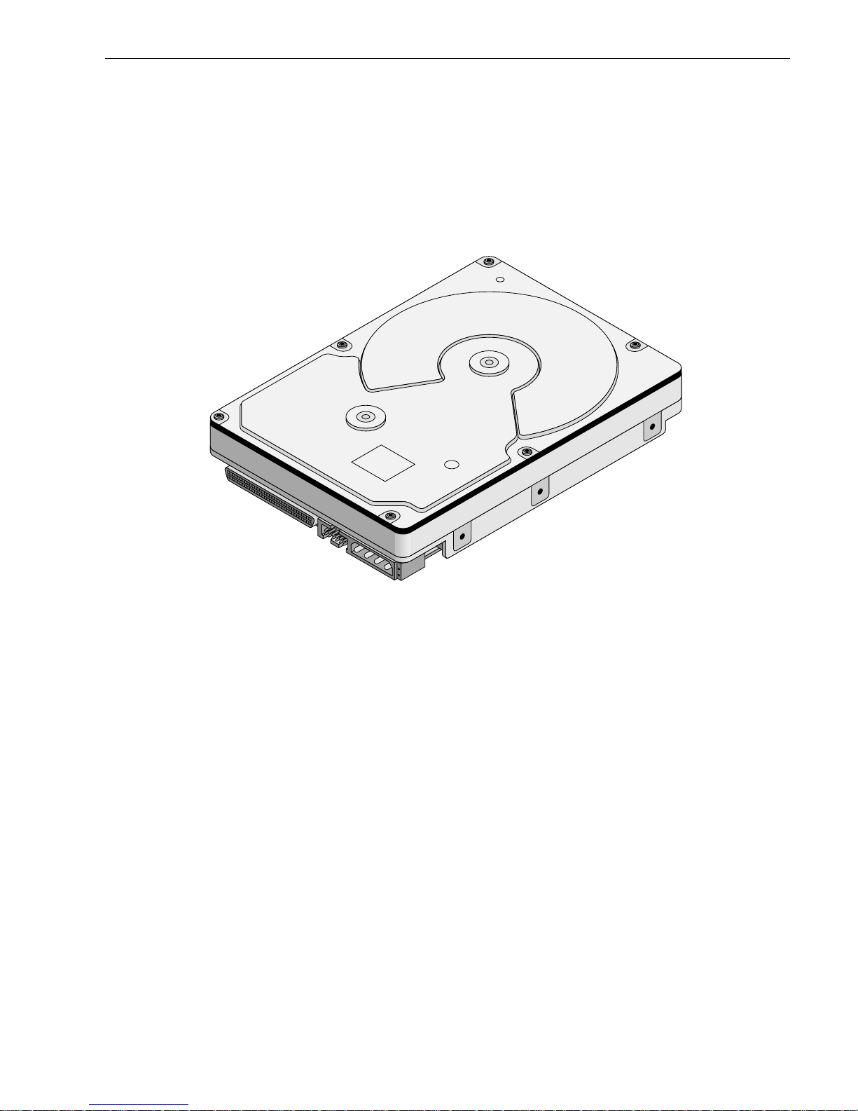
Figure 1. Cheetah 36ES family drive (ST336706LC shown). . . . . . . . . . . . . . . . . . . . . . . . . . . . . . . . . . 1
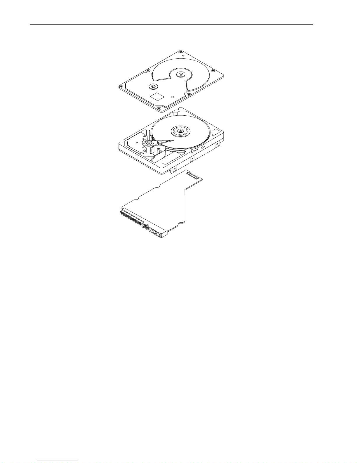
Figure 2. Cheetah 36ES family drive. . . . . . . . . . . . . . . . . . . . . . . . . . . . . . . . . . . . . . . . . . . . . . . . . . . . 6
Figure 3. Typical ST336706 drive +12 V current profile . . . . . . . . . . . . . . . . . . . . . . . . . . . . . . . . . . . 25
Figure 4. Typical ST318406 drive +12 V current profile . . . . . . . . . . . . . . . . . . . . . . . . . . . . . . . . . . . . 25
Figure 5. Typical ST336706 drive +5 V current profile . . . . . . . . . . . . . . . . . . . . . . . . . . . . . . . . . . . . 26
Figure 6. TypicalST318406 drive +5 V current profile . . . . . . . . . . . . . . . . . . . . . . . . . . . . . . . . . . . . . . 26
Figure 7. ST336706 DC current and power vs. input/output operations per second. . . . . . . . . . . . . . . 27
Figure 8. ST318406 DC current and power vs. input/output operations per second. . . . . . . . . . . . . . . 28
Figure 9. Location of HDA Temperature Check Point. . . . . . . . . . . . . . . . . . . . . . . . . . . . . . . . . . . . . . 29
Figure 10. Recommended mounting . . . . . . . . . . . . . . . . . . . . . . . . . . . . . . . . . . . . . . . . . . . . . . . . . . . . 31
Figure 11. LW mounting configuration dimensions . . . . . . . . . . . . . . . . . . . . . . . . . . . . . . . . . . . . . . . . . 33
Figure 12. LC mounting configuration dimensions . . . . . . . . . . . . . . . . . . . . . . . . . . . . . . . . . . . . . . . . . 34
Figure 13. J6 jumper header . . . . . . . . . . . . . . . . . . . . . . . . . . . . . . . . . . . . . . . . . . . . . . . . . . . . . . . . . . 38
Figure 14. J5 jumper header (on LW model only) . . . . . . . . . . . . . . . . . . . . . . . . . . . . . . . . . . . . . . . . . . 39
Figure 15. J2 option select header . . . . . . . . . . . . . . . . . . . . . . . . . . . . . . . . . . . . . . . . . . . . . . . . . . . . . 40
Figure 16. LW model drive physical interface (68-pin J1 SCSI I/O connector) . . . . . . . . . . . . . . . . . . . . 55
Figure 17. LC model drive physical interface (80-pin J1 SCSI I/O connector) . . . . . . . . . . . . . . . . . . . . 55
Figure 18. SCSI daisy chain interface cabling for LW drives. . . . . . . . . . . . . . . . . . . . . . . . . . . . . . . . . . 58
Figure 19. Nonshielded 68 pin SCSI device connector used on LW drives . . . . . . . . . . . . . . . . . . . . . . 59
Figure 20. Nonshielded 80 pin SCSI “SCA-2” connector, used on LC drives . . . . . . . . . . . . . . . . . . . . . 60
Figure 21. LVD output signals . . . . . . . . . . . . . . . . . . . . . . . . . . . . . . . . . . . . . . . . . . . . . . . . . . . . . . . . . 66
Figure 22. Typical SE-LVD alternative transmitter receiver circuits . . . . . . . . . . . . . . . . . . . . . . . . . . . . 66

Cheetah 36ES Product Manual, Rev. A 1
1.0 Scope
This manual describes Seagate Technology® LLC Cheetah 36ES™ disc drives.
Cheetah 36ES dri ves support the Sm all Computer System Interface (SCSI) as described in the ANSI SCSI
interface specifications to the extent descr ibed i n this ma nual. The SCSI Interface Product Manual, part num-
ber 75789509, descr ibes general SCSI interface characteristic s of this and other families of Seagate drives.
The SCSI Interface Product Manual references information from the documents listed in Section 2.3.
From this point on in this produc t manual the reference to Cheetah 36ES models is r eferred to as “the drive”
unless references to individual models are necessary.
Figure 1. Cheetah 36ES family drive (ST336706LC shown)

2 Cheetah 36ES Product Manual, Rev. A

Cheetah 36ES Product Manual, Rev. A 3
2.0 Applicable standards and reference documentation
The drive has been developed as a system peripheral to the highest standards of design and construction. The
drive depends upon i ts host equip ment to provide adequ ate power and environment i n order to achieve optimum performance and compli ance with applicable industry and governm ental regulations. Special attention
must be given in the areas of safety, power distribution, shielding, audible noise control, and temperature regulation. In particular, the drive must be secur e ly mo unte d i n o rd er to guara ntee the s pec if ied per for ma nc e char acteristics. Mounting by bottom holes must meet the requirements of Section 8.4.
2.1 Standards
The Cheetah 36ES family complies with Seagate standards as noted in the appropriate sections of this Manual
and the Seagate SCSI Interface Product Manual, part number 75789509.
The Cheetah 36ES disc dr ive is a UL recognized component per UL1950, CSA cer tified to CSA C22.2 No.
950-95, and VDE certified to VDE 0805 and EN60950.
2.1.1 Electromagnetic compatibility
The drive, as delivered, is designed for system integration and installation into a suitable enclosure prior to use.
As such the drive is suppli ed as a subassembly and is not su bject to Subpar t B of Part 15 of the FCC Rules
and Regulations nor the Radio Interference Regulations of the Canadian Department of Communications.
The design characteristics of the drive serve to minimize radiation when installed in an enclosure that provides
reasonable shielding. As such, the drive is capable of meeting the Class B limits of the FCC Rules and Regulations of the Canadian Department of Communications when properly packaged. However, it is the user’s
responsibility to assure that the drive meets the appropriate EMI req uirements in their syst em. Shielded I/O
cables may be required if the e nclosure does not provide ad equate sh ielding. If the I/O c ables are externa l to
the enclosure, shielded cables should be used, with the shields grounded to the enclosure and to the host controller.
2.1.2 Electromagnetic susceptibility
As a component assembly, the drive is not required to meet any susceptibility per formance requ irements. It is
the responsibility of tho se integrating the dr ive within their sy stem s to perform thos e tests req uired and design
their system to ensu re that equipment operating in the sam e system as the drive or external to the s ystem
does not adversely affect the performance of the drive. See Section 5.1.1 and T able 2, DC power requirements.
2.2 Electromagnetic compliance
Seagate uses an independ ent laboratory to co nfirm compliance to the directives/standard(s) for CE Mark ing
and C-Tick Marking. The drive was tested in a representative system for typical applications. The selected system represents the most popular characteristics for test platforms. The system configurations include:
• Typical current use microprocessor
• 3.5-inch floppy disc drive
• Keyboard
• Monitor/display
•Printer
• External modem
•Mouse
Although the test system wi th this Seag ate mode l co mpl ie s to the dire cti ves/standa rd(s ), we cann ot gua rante e
that all systems will comply. The computer manufacturer or system i ntegrator shall confir m EMC complian ce
and provide CE Marking and C-Tick Marking for their product.
Electromagnetic compliance for the European Union
If this model has the CE Marki ng it complies with the European Union requirem ents of the Electromagnetic
Compatibility Direc tive 89/336/EEC o f 03 May 1989 as ame nded by Direct ive 92/31/EE C of 28 Ap r il 1992 an d
Directive 93/68/EEC of 22 July 1993.

4 Cheetah 36ES Product Manual, Rev. A
Australian C-Tick
If this model has the C-Tick Markin g it complies with the Australia/New Zea land Standard A S/NZS3548 199 5
and meets the Electro magnetic Compatibility (EMC) Framework requirements of Australia’s Spectrum Management Agency (SMA).
Korean MIC
If this model has the Korean Ministry of Information and Communication (MIC) logo, it complies with paragraph
1 of Articl e 11 of the Ele ctromagneti c Compatib ility (EM C) Control Regu lation and meets th e Electroma gnetic
Compatibility Framework requirements of the Radio Res earch Laboratory (RRL) Minis try of Information and
Communication Republic of Korea.
This drive has been tested an d compli es with the Electroma gnetic I nterference/Elect romagnetic Suscep tibility
(EMI/EMS) for Class B products.
• EUT name (model numbers): ST336706LW, ST336706LC, ST318406LW, and ST318406LC.
• Certificate number: E-H011-01-2540(B), E-H011-01-2533(B), E-H011-01-2539(B), and E-H011-01-2532(B).
• Trade name or applicant: Seagate T echnology International
• Manufacturing start date: June 2001
• Manufacturer/nationality: Singa pore
Taiwanese BSMI
If this model has two Chinese words meani ng “EMC cer ti fication ” followed by an eight digit identification number, as a Marking, it complies with Chinese Na tional Standard (CNS) 13438 and meets the Electromagnetic
Compatibility (EMC) Framework requirements of the Taiwanese Bureau of Standa rds, Metrology, and Inspection (BSMI).
2.3 Reference documents
Cheetah 36ES Installation Guide Seagate P/N 100141983
Safety and Regulatory Agency Spec ifi catio ns Seagate P/N 75789512
SCSI Interface Product Manual Seagate P/N 75789509
Applicable ANSI Small Computer System Interface (SCSI) document numbers:
T10/1143D Enhanced SCSI Parallel Interface (EPI)
T10/1236D Primar y Comm and s-2 (S PC -2 )
T10/996D SCSI Block Commands (SBC)
T10/1157D SCSI Architectural Mode l-2 (S AM - 2)
T10/1302D SCSI Parallel Interface (SPI-3)
SFF-8451, SCA-2 Unshielded Connections
Package Test Specification Seagate P/N 30190-001 (under 100 lb.)
Package Test Specification Seagate P/N 30191-001 (over 100 lb.)
Specification, Acoustic Test Requirements, and Procedures Seagate P/N 30553-001
In case of conflict between this document and any referenced document, this document takes precedence.

Cheetah 36ES Product Manual, Rev. A 5
3.0 General description
Cheetah 36ES drives combine giant magnetoresistive (GMR) heads, partial response/maximum likelihood
(PRML) read channel el ectroni cs, embedd ed ser vo tech nology, and a wide SCSI Ultra16 0 interface to provide
high performance, high capaci ty data storage for a variety of syste ms incl uding en ginee ring work statio ns, network servers, mainframes, and supercomputers.
Ultra160 SCSI uses negotiated transfer rates. These transfer rates will occur only if your host adapter supports
these data transfer rates and is compatible with the required hardware requirements of the I/O circuit type. This
drive also operates at Ultra160 data transfer rates.
Table 1 lists the features that differentiate the Cheetah 36ES models.
Table 1: Drive model number vs. differentiating features
[1] See Section 9.6 for details and definitions.
The drive records and recovers data on approximately 3.75-inch (95 mm) non-removable discs.
The drive suppor ts the Small Computer System Interface (SCSI) as described in the ANSI SCSI interface
specifications to the extent des cri bed i n this ma nual (Volume 1), which defines the pr oduct performa nce c haracteristics of the Cheetah 36ES family of drives, and the SCSI Interface Product Manual, part number
75789509, which des cribes the general interface characteristi cs of this and other families of Seagate SCSI
drives.
The drive’s interface supports multiple ini tiators, disconne ct/reco nnect, and au tomatic features that relieve the
host from the necessity of knowing the physical characteristics of the targets (logical block addressing is used).
The head and disc assembly (HDA) is sealed at the factory. Air circulates within the HDA through a nonreplaceable filter to maintain a contamination-free HDA environment.
Refer to Figure 2 for an exploded view of the drive. This exploded view is for information only—never disassemble the HDA and do not attempt to service items in the seal ed enclo sure (h eads, med ia, actuat or, etc.) as this
requires special facilities. The drive contains no replaceable parts. Opening the HDA voids your warranty.
Cheetah 36ES drives use a dedicated landing zone at the innermost radius of the media to eliminate the possibility of destroying or degrading da ta by landing in the d ata zone. The drive automa tically goes to the landing
zone when power is removed.
An automatic shipping lock prevents potential damage to the heads and discs that results from movement during shipping and ha ndl ing . T he shi ppi ng lock au toma tic al ly di se nga ges whe n power is applied to the drive and
the head load process begins.
Cheetah 36ES drives decode track 0 location data from the servo data embedded on each surface to eliminate
mechanical transducer adjustments and related reliability concerns.
Model number
Number
of active
heads I/O circuit type [1]
Number of I/O
connector pins
Number of I/O
data bus bits
Data buffer
size (MB)
ST336706LW 4 Single-ended (SE) and low
voltage differential (LVD)
68 16 4
ST336706LC 4 Single-ended (SE) and low
voltage differential (LVD)
80 16 4
ST318406LW 2 Single-ended (SE) and low
voltage differential (LVD)
68 16 4
ST318406LC 2 Single-ended (SE) and low
voltage differential (LVD)
80 16 4
6 Cheetah 36ES Product Manual, Rev. A
A high-performance actuator assembly with a low-inertia, balanced, patented, straight-arm design provides
excellent performance with minimal power dissipation.
Figure 2. Cheetah 36ES family drive

Cheetah 36ES Product Manual, Rev. A 7
3.1 Standard features
The Cheetah 36ES family has the following standard features:
• Integrated Ultra160 SCSI controller
• Multimode SCSI drivers and receivers—single-ended (SE) and low voltage differential (LVD)
• 16 bit I/O data bus
• Asynchronous and synchronous data transfer protocol
• Firmware downloadable via SCSI interface
• Selectable even byte sector sizes from 512 to 4,096 bytes/sector
• Programmable sector reallocation scheme
• Flawed sector reallocation at format time
• Programmable auto write and read reallocation
• Reallocation of defects on command (post format)
• Enhanced ECC maximum burst corre ction length of 240 bits with a guaranteed burst correction le ngth of
233 bits
• Sealed head and disc assembly
• No preventative maintenance or adjustment required
• Dedicated head landing zone
• Embedded servo design
• Self diagnostics performed when power is applied to the drive
• 1:1 Interleave
• Zoned bit recording (ZBR)
• Vertical, horizontal, or top down mounting
• Dynamic spindle brake
• 4,096 kbyte data buffer
• Hot plug compatibility (Section 9.6.4.2 lists proper host connector needed) for LC model drives
• Drive Self Test (DST)
3.2 Media characteristics
The media used on the dr ive has a diam et er of a pproximatel y 37 5 inc he s (95 mm ) . Th e alu mi num substra te is
coated with a thin film magneti c mat eria l, overcoated with a propr iet ar y prote ctive layer for improved durability
and environmental protection.
3.3 Performance
• Supports industry standard Ultra160 SCSI interface
• Programmable multi-segmentable cache buffer (see Section 3.1)
• 10,028 RPM spindle. Average latency = 2.99 ms
• Command queuing of up to 64 commands
• Background processing of queue
• Supports start and stop commands (spindle stops spinning)
3.4 Reliability
• 1,200,000 hour MTBF
• LSI circuitry
• Balanced low mass rotary voice coil actuator
• Incorporates industry-standard Self-Monitoring, Analysis and Reporting Technology (S.M.A.R.T.)
• 5-year warranty

8 Cheetah 36ES Product Manual, Rev. A
3.5 Formatted capacities
Formatted capacity depends on the number of spare reallocation sectors reserved and the number of bytes per
sector. The following table shows the standar d OEM model read capacities data. Total LBAs = read cap acity
data (shown below) +1.
Notes.
[1] Sector size selectable at for mat time. Users having the necessar y eq uipment may modify the data block
size before issuing a format co mmand and obtain different formatted capa cities than those listed. See
Mode Select command and Format command in the SCSI Interface Product Manual, part number
75789509.
[2] User available capacity depends on spare reallo cation scheme selec ted, the number of data tracks per
sparing zone, and the number of alternate sectors (LBAs) per sparing zone.
3.6 Programmable drive capacity
Using the Mode Select command, the drive can change its capacity to something less than maximum. See the
Mode Select Parameter List table in the SCS I Interface Product Manual, par t number 7578 9509. Refer to the
Parameter list block descriptor number of blocks field. A value of zero in the number of blocks field indi cates
that the drive shall not change the capacity it is curr ently formatte d to have. A number in the number of blocks
field that is less than the ma ximum number of L BAs changes the total drive capacity to the value in the block
descriptor number of blocks field. A value greater th an the max imum number of LB As is round ed down to th e
maximum capacity.
3.7 Factory installed accessories
OEM Standard drives are shipped with the Cheetah 36ES Installation Guide, part number 100141983, and the
Safety and Regulatory Ag ency Spec ific ations , part number 75789512, unles s other wise sp ecified. The factor y
also ships with the drive a small bag of jumper plugs used for the J2, J5, and J6 option select jumper headers.
3.8 Options (factory instal led)
All customer request ed options are incorporate d during production or packaged at the manufacturi ng facility
before shipping. Some of the options available are (not an exhaustive list of possible options):
• The Cheetah 36ES Installation Guide, part number 100141983, is usually included with each standard OEM
drive shipped, but extra copies may be ordered.
• The Safety and Regulatory Agency Specifications, par t number 75789512, is usually include d with each
standard OEM drive shipped, but extra copies may be ordered.
Formatted
(data block size
512 bytes/sector) [1]
ST336706 445DCC9h (36.704 GB) [2]
ST318406 222EE55h (18.352 GB) [2]

Cheetah 36ES Product Manual, Rev. A 9
4.0 Performance characteristics
4.1 Internal drive characteristics (transparent to user)
4.2 SCSI performance characteristics (visible to user)
The values given in Section 4.2.1 apply to all models of the Cheetah 36ES family unl ess otherwise s pecified.
Refer to Section 9.10 and to the SC SI Interface Product Manual, part number 757895 09, for addit ional tim ing
details.
4.2.1 Access time [5]
4.2.2 Format command execution time (minutes) [1]
4.2.3 Generalized performance characteristics
Data buffer transfer rate to/from disc media (one contiguous 512-byte sector):
Data buffer transfer rate to/from disc media (<1 track)
ST336706 ST318406
Drive capacity 36.704 18.352 GByte (formatted, rounded off values)
Read/write heads 4 2
Bytes/track 348,900 348,900 Bytes (average, rounded off values)
Bytes/surface 9,176 9,176 Mbytes (unformatted, rounded off values)
Tracks/surface (total) 26,302 26,302 Tracks (user accessible)
Tracks/inch 38,000 38,000 TPI
Peak bits/inch 460.00 460.00 KBPI
Internal data rate 530-674 530-674 Mbits/sec (variable with zone)
Disc rotational speed 10,028 10,028 r/min (+
0.5%)
Average rotational latency 2.99 2.99 msec
Including controller overhead
(without disconnect) [1] [3]
Not including controller overhead
(without disconnect) [1] [3]
Drive level Drive level
Read Write Read Write
msec msec
Average—Typical [2] 5.4 6.4 5.2 6.2
Single Track—Typical [2] 0.7 1.1 0.5 0.9
Full Stroke—Typical [2] 10.2 11.2 10.0 11.0
ST336706 ST318406
Maximum (with verify) 25 12.5
Maximum (no verify) 13 6.5
Minimum sector interleave 1 to 1
Minimum [3] 52 MByte/sec
Average [3] 62 MByte/sec
Maximum [3] 68 MByte/sec
Minimum [3] 48 MByte/sec
Average [3] 58 MByte/sec
Maximum [3] 62 MByte/sec

10 Cheetah 36ES Product Manual, Rev. A
SCSI interface data transfer rates (asynchronous):
Maximum instantaneous 8 bit wide 5.0 Mbytes/sec [4]
Maximum instantaneous 16 bit wide 10.0 Mbytes/sec [4]
Synchronous formatted transfer rates: Ultra2 SCSI Ultra160 SCSI
In SCSI Wide (16 bit) 10.0 to 80 Mbytes/sec 10.0 to 160 Mbytes/sec [6]
Sustainable data transfer rates:
Minimum 39 Mbytes/sec
Average 47 Mbytes/sec
Maximum 51 Mbytes/sec
Sector Sizes:
Default 512 byte user data blocks
Variable 512 to 4,096 bytes per sector in even number of bytes per sector.
If n (number of bytes per sector) is odd, then n-1 will be used.
Notes for Section 4.2.
[1] Execution time measured from receipt of the last byte of the Command Descr iptor Block (CDB) to the
request for a Status Byte Tr ansfer to the Initiator (excluding connect/disconnect).
[2] Typical access times are meas ured und er nomina l condition s of temperat ure, voltage, and hor izontal or i-
entation as measured on a representative sample of drives.
[3] Assumes no errors and no sector has been relocated.
[4] Assumes system ability to support the rates listed and no cable loss.
[5] Access time = controller overhead + average seek time.
Access to data = controller overhead + average seek time + latency time.
[6] Drive required to be in LVD mode to attain maximum transfer rates.
4.3 Start/stop time
After DC power at no minal voltage h as been appl ied, the d r ive becom es rea dy withi n 20 sec onds if the Mo tor
Start Opti on is disabled (i.e. the motor star ts as soon as the power has bee n applied). If a recoverable error
condition is detected during the start sequence, the drive executes a recovery procedure which may cause the
time to become rea dy to exceed 20 seconds. Dur ing spin up to ready time the dr ive responds to s ome commands over the SCSI interface in less than 1.5 seconds afte r application of power. Stop time is less than 15
seconds from removal of DC power.
If the Motor Star t Option is en abled, the inter nal cont roller accep ts the comm ands lis ted in the SCSI Inter face
Product Manual less tha n 1.5 s econ ds after DC power has bee n appl ied. A fter the Motor Start Command has
been received the d rive becomes ready for nor mal o perations withi n 16 seco nds typic ally (excluding an error
recovery procedure). The Mo tor Start Comm and can also be used to comm and the drive to stop the spindle
(see SCSI Interface Product Manual, part number 75789509).
There is no power control switch on the drive.
4.4 Prefetch/multi-segmented cache control
The drive provides prefetch (read look-ahead) and multi-segmented cache control algorithms that in many
cases can enhance system performance. “Cache” as used herein refers to the drive buffer storage space when
it is used in cache operations. To select prefetch and cache features the host sends the Mode Select command
with the proper values in the ap plicable bytes in Mode Page 08h (see SCSI Interface Product Manual, part
number 75789509). Pre fetch and cache operation are independent features from the s tandpoint that each is
Read/write consecutive sectors on a track Yes
Flaw reallocation performance impact (for flaws reallocated at format
time using the spare sectors per sparing zone reallocation scheme.)
Negligible
Average rotational latency 2.99 msec

Cheetah 36ES Product Manual, Rev. A 11
enabled and disabled independentl y vi a the Mod e Sele ct com mand. However, in actual operation the prefetch
feature overlaps cache operation somewhat as is noted in Section 4.5.1 and 4.5.2.
All default cache and prefetch Mode pa rameter values (Mode Page 08h) for standard OEM versions of this
drive family are given in Tables 7 and 8.
4.5 Cache operation
In general, 4096 kbytes of the physical buffer space in the drive can be u se d as storage s pac e for cache oper ations. The buffer can be divided into logical segm ents (Mode Select Page 08h, byte 13) from which data is
read and to which data is written. The drive maintains a table of logical block disk medium ad dresses of the
data stored in each segment of the buffer. If cache operation is enabled (RCD bit = 0 in Mode Page 08h, byte 2,
bit 0. See SCSI Interface Prod uct Manual, part numb er 75789509), data requested by the host with a Read
command is retrieved from the buffer (if it is there), before any disc access is initiated. If cache operation is not
enabled, the buffer (still segmented with required numb er of segments ) is still use d, but only as circula r buffer
segments during d isc medium read op erations (disregard ing Prefetch operation for the moment) . That is, the
drive does not check in the buffer segments for the requested read data, but goes di rectly to the medium to
retrieve it. The retrieved data merely passes thr ou gh some buffer segment on the way to the host. On a cache
miss, all data transfers to the host are in accordance with buffer-full ratio rules. On a cache hit the drive ignores
the buffer-full ratio rules. See explanations as sociated with Mode p age 02h (disconne ct/reconnect contr ol) in
the SCSI Interface Product Manual.
The following is a simplified description of a read operation with cache operation enabled:
Case A - A Read command is received and the first logical block (LB) is already in cache:
1. Drive transfers to the initiator the first LB requeste d plu s all subsequent contiguous LBs that ar e already in
the cache. This data may be in multiple segments.
2. When the requested LB is reached that is not in any cache segment, the drive fetches it and any remaining
requested LBs from the disc an d puts them in a s egment of the cache. The dr ive transfers the remainin g
requested LBs from the ca che to t he host in accorda nce with the disconn ect/r econn ect speci fication mentioned above.
3. If the prefetch feature is enabled, refer to Section 4.5.2 for operation from this point.
Case B - A Read command requests data, the first LB of which is not in any segment of the cache:
1. The drive fetches the requested LBs from the disc and transfers them into a segment, and from there to the
host in accordance with the disconnect/reconnect specification referred to in case A.
2. If the prefetch feature is enabled, refer to Section 4.5.2 for operation from this point.
Each buffer segment is actually a self-contained circular storage area (wrap-around occurs), the length of
which is an integer number of disc medium sectors. The wrap-around capab ility of the individual segments
greatly enhances the buffer’s overall performance as a cache storage, allowing a wide range of user selectable
configurations, which inc ludes their use in the pre fetch operation (if enabled), even when cache operation is
disabled (see Section 4.5.2). T he number of segmen ts may be selected us ing the M ode Select comm and, but
the size can not be direc tly selected. Size is se lected only as a by-prod uct of selecting the s egment number
specification. The size in Kbytes of each segment is not repor ted by the Mode Sense comman d page 08h,
bytes 14 and 15. The value 0x0000 is always reported. If a size specifi cation is sent by the host in a Mod e
Select command (bytes 14 an d 1 5) n o n ew segm ent size is set up by the d rive, and if the STRICT bi t i n Mod e
page 00h (byte 2, bit 1) is set to one, the dr ive responds as it doe s for any attempt to change u nchangeable
parameters (see SCSI Interface Product Manual, part number 75789509). The drive supports operation of any
integer number of segments from 1 to 32. The default number of segments is defined in Tables 7 and 8.
4.5.1 Caching write data
Write caching is a wr ite op eration by the dr ive that makes use of a drive buffer storage area where the data t o
be written to the medium is stored in one or more segments while the drive performs the write command.
If read caching is enabled (RCD=0), then data written to the medium is retained in the cache to be made available for future read cache hits. The same buffer space and segme ntat ion is u sed a s set up for read func tions.
The buffer segmentation scheme is set up or changed independently, having nothing to do with the state of

12 Cheetah 36ES Product Manual, Rev. A
RCD. When a write comma nd is issued, if RCD=0 , the cache is first checked to see if any logical blocks that
are to be writte n are already stored in the cach e from a previous read or write comman d. If there are, the
respective cache segments are cleared. The new data is cached for subsequent Read commands.
If the number of wri te data lo gical blocks exceeds t he size of t he segme nt being w ritte n into, when the end o f
the segment is reached, the data is written into the beginning of the same cache segment, overwriting the data
that was written there at the beginning of the operation. Howev er, the drive does not overwrite data that has not
yet been written to the medium.
If write caching is enabled (WCE=1), then the drive may return Good status on a write command after the data
has been transferred into the cache, but before the data has been written to the medium. If an error occurs
while writing the data to the medium, and Good status has already been returned, a deferred error will be generated.
The Synchronize Cache command may be used to force the drive to write all cached write data to the medium.
Upon completion of a Synchronize Cache command, all data received from previous write commands will have
been written to the medium.
Tables 7 and 8 show Mode default settings for the drives.
4.5.2 Prefetch operation
If the Prefetch feature is enabled, data in conti guous lo gical blocks on the disc immedia tely b eyond that which
was requested by a Read comman d can be retri eved and stored in the buffer for immediate transfer from the
buffer to the host on subsequent Read commands that request those logical blocks (this is true even if cache
operation is disabled). Though th e prefetch operation us es the buffer as a cache, findin g the r equ es ted data i n
the buffer is a prefetch hit, not a cache operation hit. Prefetch is enabled using Mode Select page 08h, byte 12,
bit 5 (Disable Read Ahead - DRA bit). DRA bit = 0 enables prefetch. Since data that is prefetched replaces data
already in some buffer segment(s), the host can limit the am ount of prefetch data to optimize s ystem performance. The max prefetch field (bytes 8 and 9) limits the amount of prefetch. The drive does not use the
Prefetch Ceiling field (bytes 10 and 11).
During a prefetch operation, the dri ve crosses a cyl inder bou ndar y to fetch more data o nly if the Discontinuity
(DISC) bit is set to one in bit 4 of byte 2 of Mode parameters page 08h.
Whenever prefetch (read look-ahead) is enabled ( enabled by DRA = 0), it opera tes und er the co ntrol of ARLA
(Adaptive Read Look-Ahead). If the host uses software interleave, ARLA enables prefetch of contiguous blocks
from the disc when it sense s that a prefetch hit will l ikely occur, even if two consecutive read operations were
not for physically contiguous blocks of data (e.g., “software interleave”). ARLA disables prefetch when it
decides that a prefetch hit will not li kely occu r. If the host is not usin g so ftware interleave, and if two sequential
read operations are not for contiguous blocks of data, ARLA dis ables prefetch, but as long as sequential read
operations request contiguous blocks of data, ARLA keeps prefetch enabled.
4.5.3 Optimizing cache performance for desktop and server applications
Desktop and server applications require different drive caching operations for optimal performance. This
means it is difficult to provide a single configuration that meets both of these needs. In a desktop environment,
you want to configure the cache to r espond quickly to repetiti ve accesses of multiple s mall segments of dat a
without taking the time to “ look ahea d” to the next contiguous s egments of da ta. In a ser ver environment, you
want to configure the cac he to provide large volumes of sequential data in a non-repetitive manner. In this
case, the ability of the cache to “look a head” to the next contiguous segments of sequential data is a good
thing.
The Performance Mode (PM) bit contr ols the way the drive switches the cache buffer into different modes o f
segmentation. In “ser ver mode” (PM bit = 0), the dr ive can increase the number of cache buffer segments
above the value defined in Mode Page 8, Byte 13, as neede d to o ptim ize the perfor ma nc e, based on the command stream from the host. In “desktop mode” (PM bit = 1), the number of segments is maintained at the value
defined in Mode Page 8, Byte 13, at all times. For additional infor mation about the PM bit, refer to the Unit
Attention Parameters page (00h) of the Mode Sense command ( 1Ah) in the SCSI Interface Produ ct Manual,
part number 75789509.
Cheetah 36ES Product Manual, Rev. A 13
The base cache buffer configuration for desktop o r server environments needs to be set co rrectly by the host
system. This involves setting the PM bit in M ode Page 0, Byte 2, as well as the numbe r of cache buffer segments in Mode Page 8, Byte 13. The firm ware default values are set to desktop mode (PM bit = 1), and the
number of cache buffer segments set to 16 (10h). The OEM saved values for drives with LW interface is the
same as the fir mware default values. For drives with th e LC interface, the OEM saved values are ch anged to
server mode (PM bit=0), and the number of cache buffer segments are set to 3 (03h). Refer to Ta bles 9a
through 9f in Section 9.3.2 for drive default values for the PM bit in Mode Page 0, Byte 2 and the number of
cache buffer segments in Mode Page 8, Byte 13.
Caching Parameters page (08h)
Byte 13 (Number of Cache Segments)
Unit Attention Parameters page (00h)
Byte 2, Bit 7 (PM bit)
Desktop mode 10h (16 segments -- default for LW models)
1
Server mode 03h (3 segments -- default for LC models)
0

14 Cheetah 36ES Product Manual, Rev. A

Cheetah 36ES Product Manual, Rev. A 15
5.0 Reliability specifications
The following reliability spe cifications assume correct hos t/drive operational interface, including all interface
timings, power supply voltages, environmental requirements and drive mounting constraints (see Section 8.4).
Note.
[1] Error rate specified with automatic retries and data correction with ECC enabled and all flaws reallocated.
5.1 Error rates
The error rates stated in this specification assume the following:
• The drive is operated per this specification using DC power as defined in this manual (see Section 6.2).
• The drive has been formatted with the SCSI Format command.
• Errors caused by media d efects or host sy stem failures are excluded fr om erro r rate comp utation s. Refer to
Section 3.2, “Media Characteristics.”
• Assume random data.
5.1.1 Environmental interference
When evaluating systems operatio n under condit ions of Ele ctromagnetic Interference (EMI), the performanc e
of the drive within the s ystem shall b e consi dered acce ptable if the dr ive does not g enerate an unre coverable
condition.
An unrecoverable error, or unrecoverable condition, is defined as one that:
• Is not detected and corrected by the drive itself;
• Is not capable of being detected from the error or fault status provided through the drive or SCSI interface; or
• Is not capable of being recovered by normal dr ive or sys tem re covery pro ce dures wit hou t opera tor inte rven-
tion.
5.1.2 Read errors
Before determination or measurement of read error rates:
• The data that is to be used for measurement of read error rates must be verified as being written correctly on
the media.
• All media defect induced errors must be excluded from error rate calculations.
5.1.3 Write errors
Write errors can occur as a result of media defects, environmental interference, or equipm ent malfunction.
Therefore, write errors are not predictable as a function of the number of bits passed.
If an unrecoverable write error occurs beca use of a n equipm ent mal functi on in the dr ive, the error is classi fied
as a failure affecting MTBF. Unrecoverable write errors are those which cannot be corrected within two
attempts at writing the record with a read verify after each attempt (excluding media defects).
5.1.4 Seek errors
A seek error is de fin ed as a failure o f t he drive to position the h eads to t he addressed track. There sh all b e n o
more than ten recoverable seek errors in 10
8
physical seek operations. After detecting an init ia l se ek err or, the
drive automatically per forms an error rec overy process. If the error r ecovery process fails, a seek posi tioning
Seek Errors
Less than 10 in 10
8
seeks
Read Error Rates [1]
Recovered Data Less than 10 errors in 10
12
bits transferred (OEM default settings)
Unrecovered Data Less than 1 sector in 10
15
bits transferred (OEM default settings)
Miscorrected Data Less than 1 sector in 10
21
bits transferred
MTBF 1,200,000 hours
Service Life 5 years
Preventive Maintenance None required

16 Cheetah 36ES Product Manual, Rev. A
error (15h) is repor ted wit h a Medium err or (3h) or Har dware error (4h) repo r ted in the Sense Key. This is an
unrecoverable seek error. Unrecoverable seek errors are classified as failures for MTBF calculatio ns. Refer to
the SCSI Interface Product Manual, part number 75789509, for Request Sense information.
5.2 Reliability and service
You can enhance the reliability of Cheetah 36ES disc drives by ensuring that the drive receives adequate cooling. Section 6.0 pr ovides tempe rature me asurements and othe r information that may be used to en hance the
service life of the drive.
5.2.1 Mean time between failure
The production disc dr ive shall achieve an MTBF of 1,200,000 hours when operated in an environment that
ensures the case temp eratures are not exceeded. Shor t-term excursions up to th e specification limits of th e
operating environment will no t affect MTBF performance. Continual or s ustained operation at case temperatures above the values specified in Section 6.4.1 may degrade product reliability .
The MTBF target is specified as device power-on hours (POH) for all drives in service per failure.
Estimated power-on operating hours in the period = MTBF per measurement period
Number of drive failures in the period
Estimated power-on operation hours means power-up hours per disc drive times the total number of disc drives
in servic e. Each dis c dr ive shal l have accumulated a t leas t nine month s of o peration. Data sha ll be calc ulated
on a rolling average base for a minimum period of six months.
MTBF is based on the following assumptions:
• 8,760 power-on hours per year.
• 250 average on/off cycles per year.
• Operations at nominal voltages.
• Systems will provide adequate cooling to ensure the cas e temperatures speci fied in Section 6.4.1 are not
exceeded.
Drive failure means any stoppage or substandard performance caused by drive malfunction.
A S.M.A.R.T. predictive failure indicates that the dr ive is dete riora ting to an imm inent failure and is consi dere d
an MTBF hit.
5.2.2 Preventive maintenance
No routine scheduled preventive maintenance shall be required.
5.2.3 Service life
The drive shall have a useful ser vic e life of five years. Depot repair or repl aceme nt of maj or parts is per m itted
during the lifetime (see Section 5.2.4).
5.2.4 Service philosophy
Special equipmen t is requir ed to repair the drive HDA. In order to achi eve the above service life, repairs must
be performed only at a proper ly equip ped and staffed ser vice and repair facility. Troubleshooting and r epair of
PCBs in the field i s not recommended, be cause of the extensive diagnostic equipment required for effective
servicing. Also, there are no spare parts available for this drive. Drive warranty is voided if the HDA is opened.
5.2.5 Service tools
No special tools are requi red for site instal lat ion or recomm ended for site maintenance. Refer to Section 5.2.4.
The depot repair philosophy of the drive precludes the necessity for special tools. Field repair of the drive is not
practical since there are no user purchasable parts in the drive.

Cheetah 36ES Product Manual, Rev. A 17
5.2.6 Hot plugging Cheetah 36ES disc drives
The ANSI SPI-3 (T10 /1302D) documen t defines the physical requi rements for removal and inser tion of SCS I
devices on the SCSI bus. Four cases are addressed. The cases are differentiated by the state of the SCSI bus
when the removal or insertion occurs.
Case 1 - All bus devices powered off during removal or insertion
Case 2 - RST signal asserted continuously during removal or insertion
Case 3 - Current I/O processes not allowed during insertion or removal
Case 4 - Current I/O process allowed during insertion or removal, except on the device being changed
Seagate Cheetah 36ES disc drives support all four hot plugging cases. Provision shall be made by the system
such that a device being inserted makes power and ground connecti ons pri or to the co nnection o f any device
signal contact to the bus. A device being re moved shall maintain power and groun d connecti ons after the disconnection of any device signal contact from the bus (see T10/1302D SPI-3 Annex C).
It is the responsibility of the systems integrator to assure that no hazards from temperature, energy, voltage, or
ESD potential are presented during the hot connect/disconnect operation.
All I/O processe s for the SCSI device being i nser ted or removed shall be quiescent. A ll SCSI devices on th e
bus shall have receivers that conform to the SPI-3 standard.
If the device being hot plugged uses single-ended (SE) drivers and the bus is currently operating in low voltage
differential (LVD) mode, then all I/O processes for all devices on the bus must be completed , and the bus quiesced, before attempting to hot plug. Following the insertion of the newly installed device, the SCSI host
adapter must issue a Bus Res et, followed by a synchronous transfer negotiation. Failure to perform the SCSI
Bus Reset could result in erroneous bus operations.
The SCSI bus termination and termination power source shall be external to the device being inserted or
removed.
End users should not mix devices with high voltage differential (H VD) drivers and receivers and devices wit h
SE, LVD, or multimode drivers and receivers on the s ame SCSI bus since the commo n mode voltages in the
HVD environment may not be controlled to safe levels for SE and LVD devices (see ANSI SPI-3).
The disc drive spindle must co me to a complete st op prior to comple tely removing the dr ive from the cabinet
chassis. Use of the Stop Spin dle co mmand o r partial with drawal of the drive, enough to be disc onnec ted fro m
the power source, prior to removal are methods for insuring that this requirement is met. During drive insertion,
care should be taken to avoid exceeding the limits stated in Section 6.4.4, "Shock and vibration" in this manual.
5.2.7 S.M.A.R.T.
S.M.A.R.T. is an acronym for Self-Monitori ng Analys is and Rep or ting Technology. This technology is intended
to recognize conditions that indi cate a dri ve failure and is designed to provide suffic ient war ning of a failure to
allow data back-up before an actual failure occurs.
Note. The firmware will monitor specific attributes for degradation over time but cannot predict instantaneous
drive failures.
Each attribute ha s bee n s el ec ted to mo nit or a sp ec ifi c s et of failure c ond itio n s in the operating performanc e o f
the drive, and the thresholds are optimized to minimize “false” and “failed” predictions.
Controlling S.M.A.R.T.
The operating mode of S.M.A.R.T. is controlled by the DEXCPT bit and the PERF bi t of the “Informational
Exceptions Control Mo de Page” (1Ch). The DEXCPT bit is us ed to enable or disable the S.M.A.R.T. process.
Setting the DEXCPT bit will disable all S.M.A.R.T. functions. When enabled, S.M.A.R.T. will collect on-line data
as the drive performs nor m al re ad/wr ite operatio ns. When t he PER F bit is set, th e dr ive is consi dered to be in
“On-line Mode Only” and will not perform off-line functions.

18 Cheetah 36ES Product Manual, Rev. A
The process of measur ing off-line attributes and saving data can be forced by the RTZ command. Forcing
S.M.A.R.T. will reset the timer so that the next scheduled interrupt will be two hours.
The drive can be interrogated by the host to determine the time remaining before the next scheduled measurement and data loggi ng process will oc cur. This is accomplished by a log sense command to log page 0x3E .
The purpose is to allow the customer to control when S.M.A.R.T. interruptions occur. As described above, forcing S.M.A.R.T by the Rezero Unit command will reset the timer.
Performance impact
S.M.A.R.T. attribute data will be saved to the disc for the purpose of recreating the events that caused a predictive failure. The drive will measure and save parameters once every two hours subject to an idle per iod on the
SCSI bus. The process of m easuring off-line attr ibute data and saving data to th e disc is u ninterrup table and
the maximum delay is summarized below:
Maximum processing delay
On-line only delay Fully enabled delay
DEXCPT = 0, PERF = 1 DEXCPT = 0, PERF = 0
S.M.A.R.T. delay times ST336706:
150 ms ST336706: 270 ms
ST318406:
100 ms ST318406: 190 ms
Reporting control
Reporting i s controlled in the Informational Excep tions Control Page (1Ch). Subj ect to the repor ting method,
the firmware will is su e a 01- 5D0 0 s ense c od e to the hos t. T h e err or c ode is pr eserved through bus resets an d
power cycles.
Determining rate
S.M.A.R.T. monitors the rate at which errors occur and s ignals a pred ictive failure if the rate of degraded er ror
rate increases to an una cc ept able level. To determine rate, error events are logged and co mp ared t o th e number of total operations for a given attr ibute. The inter val defines the number of operations over which to m easure the rate. The counter that keeps track of the c urrent number of operations is referred to as the I nterval
Counter.
S.M.A.R.T. measures error rate, hence for each attr ibute the occurrence of an erro r is recorded. A counter
keeps track of the number of errors for the current interval. This counter is referred to as the Failure Counter.
Error rate is simply the number of errors per ope ration. The algorithm that S.M.A.R.T. uses to record rates of
error is to set thresholds for the number of errors and the interval. If the number of errors exceeds the threshold
before the interval expires, then the error rate is cons idered to b e unacceptable. If the numbe r of errors d oes
not exceed the threshold before the interval expires, then the error rate is considered to be acceptable. In either
case, the interval and failure counters are reset and the process starts over.
Predictive failures
S.M.A.R.T. signals predictive failures when the drive is performing unacc eptably for a period o f time. The f ir mware keeps a running count of the number of times the error rate for each attribute is unacceptable. To accomplish this, a counte r is incremen ted whenever the error rate is una cceptable and de cremented ( not to exceed
zero) whenever the error rate is acceptable. Should the counter continually be incremented such that it reaches
the predictive threshold, a predictive failure is signaled. This counter is referred to as the Failure History
Counter. There is a separate Failure History Counter for each attribute.
5.2.8 Drive Self Test (DST)
Drive Self Test (DST) is a tech nology designed to recognize d rive fault conditions that qu alify the drive as a
failed unit. DST validates the functionality of the drive at a system level.
There are two test coverage options implemented in DST:
1. extended test
2. short test
 Loading...