

Page 1

. . . . . . . . . . . . . . . . . . . . . . . . . . . . . . . . . . . . . . . . . . . . . . . . .
Barracuda 4XL Family:
. . . . . . . . . . . . . . . . . . . . . . . . . . . . . . . . . . . . . . . . . . . . . . . . .
ST34572N/W/WD/WC/DC
. . . . . . . . . . . . . . . . . . . . . . . . . . . . . . . . . . . . . . . . . . . . . . . . .
ST32272N/W/WD/WC/DC
. . . . . . . . . . . . . . . . . . . . . . . . . . . . . . . . . . . . . . . . . . . . . . . . .
. . . . . . . . . . . . . . . . . . . . . . . . . . . . . . . . . . . . . . . . . . . . . . . . .
Product Manual, Volume 1
. . . . . . . . . . . . . . . . . . . . . . . . . . . . . . . . . . . . . . . . . . . . . . . . .
Page 2

Page 3

. . . . . . . . . . . . . . . . . . . . . . . . . . . . . . . . . . . . . . . . . . . . . . . . .
Barracuda 4XL Family:
. . . . . . . . . . . . . . . . . . . . . . . . . . . . . . . . . . . . . . . . . . . . . . . . .
ST34572N/W/WD/WC/DC
. . . . . . . . . . . . . . . . . . . . . . . . . . . . . . . . . . . . . . . . . . . . . . . . .
ST32272N/W/WD/WC/DC
. . . . . . . . . . . . . . . . . . . . . . . . . . . . . . . . . . . . . . . . . . . . . . . . .
. . . . . . . . . . . . . . . . . . . . . . . . . . . . . . . . . . . . . . . . . . . . . . . . .
Product Manual, Volume 1
. . . . . . . . . . . . . . . . . . . . . . . . . . . . . . . . . . . . . . . . . . . . . . . . .
Page 4

© 1997 Seagate Tech nology, Inc. All rights reserved
Publication number: 77767500, Rev. B
November 1997
Seagate , Seagate Technology , and the Seagate logo are registered trademarks of Seagate Technology, Inc. Barracuda, SeaFAX, SeaFONE, SeaNET, SeaTDD, and SeaBOARD are either
trademarks or registered trademarks of S eagate Technol ogy, Inc. or one of its subsidiaries. All
other trademarks or registered trademarks are the property of their respective owners.
Seagate reserves the right to change, without notice, product offerings or specifications. No part
of this publication may be reproduced in any form without written permission of Seagate Technol-
ogy, Inc.
Page 5

Revision status summary sheet
Revision Date Writer/Engineer Sheets Affected
A Issue 03/26/97 L. Newman/A. Ukani 1/1, v thru viii, 1 thru 82.
B 11/04/97 L. Newman/A. Ukani 8, 9, 10, 28, 29, 30, 47, 49, 50, and 72.
Notice.
This manual is volume 1 of a two-volume document with the SCSI interface information in the Volume 2
SCSI Interface Product Manual
If you need the SCSI interf ace information, order the volume 2
number 77738479.
, part number 77738479.
SCSI Interface Product Manual
, part
Page 6

Page 7

Barr acuda 4X L P roduct Manual, Rev. B vii
Contents
1.0 Scope . . . . . . . . . . . . . . . . . . . . . . . . . . . . . . . . . . . . . . . . . . . . . . . . . . . . . . . . . . . . . . . . . . . . . . . . . . 1
2.0 Applicable standards and reference documentation. . . . . . . . . . . . . . . . . . . . . . . . . . . . . . . . . . . . 3
2.1 Standards. . . . . . . . . . . . . . . . . . . . . . . . . . . . . . . . . . . . . . . . . . . . . . . . . . . . . . . . . . . . . . . . . 3
2.1.1 Electromagnetic compatibility . . . . . . . . . . . . . . . . . . . . . . . . . . . . . . . . . . . . . . . . . . 3
2.1.2 Electromagnetic susceptibility. . . . . . . . . . . . . . . . . . . . . . . . . . . . . . . . . . . . . . . . . . 3
2.2 Electromagnetic com pliance . . . . . . . . . . . . . . . . . . . . . . . . . . . . . . . . . . . . . . . . . . . . . . . . . . 3
2.3 Reference documents . . . . . . . . . . . . . . . . . . . . . . . . . . . . . . . . . . . . . . . . . . . . . . . . . . . . . . . 4
3.0 General description. . . . . . . . . . . . . . . . . . . . . . . . . . . . . . . . . . . . . . . . . . . . . . . . . . . . . . . . . . . . . . . 5
3.1 Standard features. . . . . . . . . . . . . . . . . . . . . . . . . . . . . . . . . . . . . . . . . . . . . . . . . . . . . . . . . . . 7
3.2 Media characteristics . . . . . . . . . . . . . . . . . . . . . . . . . . . . . . . . . . . . . . . . . . . . . . . . . . . . . . . . 7
3.3 Performance. . . . . . . . . . . . . . . . . . . . . . . . . . . . . . . . . . . . . . . . . . . . . . . . . . . . . . . . . . . . . . . 7
3.4 Re liability . . . . . . . . . . . . . . . . . . . . . . . . . . . . . . . . . . . . . . . . . . . . . . . . . . . . . . . . . . . . . . . . . 7
3.5 Unformatted and formatted capacit ies . . . . . . . . . . . . . . . . . . . . . . . . . . . . . . . . . . . . . . . . . . . 8
3.6 Programmabl e drive capacity. . . . . . . . . . . . . . . . . . . . . . . . . . . . . . . . . . . . . . . . . . . . . . . . . . 8
3.7 Factory installed accessories. . . . . . . . . . . . . . . . . . . . . . . . . . . . . . . . . . . . . . . . . . . . . . . . . . 8
3.8 Options (factory installed). . . . . . . . . . . . . . . . . . . . . . . . . . . . . . . . . . . . . . . . . . . . . . . . . . . . . 8
3.9 Accessories (user installed) . . . . . . . . . . . . . . . . . . . . . . . . . . . . . . . . . . . . . . . . . . . . . . . . . . . 8
4.0 Performance characteristics . . . . . . . . . . . . . . . . . . . . . . . . . . . . . . . . . . . . . . . . . . . . . . . . . . . . . . . 9
4.1 Internal drive characteristics (transparent to user) . . . . . . . . . . . . . . . . . . . . . . . . . . . . . . . . . . 9
4.2 SCSI Seek performance characteristics (visible to user). . . . . . . . . . . . . . . . . . . . . . . . . . . . . 9
4.2.1 Access time . . . . . . . . . . . . . . . . . . . . . . . . . . . . . . . . . . . . . . . . . . . . . . . . . . . . . . . 9
4.2.2 Format command execution time (minutes) . . . . . . . . . . . . . . . . . . . . . . . . . . . . . . 10
4.2.3 Generalized performance characteristics. . . . . . . . . . . . . . . . . . . . . . . . . . . . . . . . 10
4.3 Start/stop time . . . . . . . . . . . . . . . . . . . . . . . . . . . . . . . . . . . . . . . . . . . . . . . . . . . . . . . . . . . . 11
4.4 Prefetch/multi-segmented cache control . . . . . . . . . . . . . . . . . . . . . . . . . . . . . . . . . . . . . . . . 11
4.5 Cache operation. . . . . . . . . . . . . . . . . . . . . . . . . . . . . . . . . . . . . . . . . . . . . . . . . . . . . . . . . . . 11
4.5.1 Caching write data . . . . . . . . . . . . . . . . . . . . . . . . . . . . . . . . . . . . . . . . . . . . . . . . . 12
4.5.2 Prefetch operation . . . . . . . . . . . . . . . . . . . . . . . . . . . . . . . . . . . . . . . . . . . . . . . . . 12
5.0 Reliability specifications . . . . . . . . . . . . . . . . . . . . . . . . . . . . . . . . . . . . . . . . . . . . . . . . . . . . . . . . . 15
5.1 Error rates . . . . . . . . . . . . . . . . . . . . . . . . . . . . . . . . . . . . . . . . . . . . . . . . . . . . . . . . . . . . . . . 15
5.1.1 Environmental interference. . . . . . . . . . . . . . . . . . . . . . . . . . . . . . . . . . . . . . . . . . . 15
5.1.2 Read errors. . . . . . . . . . . . . . . . . . . . . . . . . . . . . . . . . . . . . . . . . . . . . . . . . . . . . . . 15
5.1.3 Write errors. . . . . . . . . . . . . . . . . . . . . . . . . . . . . . . . . . . . . . . . . . . . . . . . . . . . . . . 15
5.1.4 Seek errors. . . . . . . . . . . . . . . . . . . . . . . . . . . . . . . . . . . . . . . . . . . . . . . . . . . . . . . 16
5.2 Re liability and serv ic e. . . . . . . . . . . . . . . . . . . . . . . . . . . . . . . . . . . . . . . . . . . . . . . . . . . . . . . 16
5.2.1 Mean time between failure . . . . . . . . . . . . . . . . . . . . . . . . . . . . . . . . . . . . . . . . . . . 16
5.2.2 Preventive maintenance . . . . . . . . . . . . . . . . . . . . . . . . . . . . . . . . . . . . . . . . . . . . . 16
5.2.3 Servi ce life . . . . . . . . . . . . . . . . . . . . . . . . . . . . . . . . . . . . . . . . . . . . . . . . . . . . . . . 16
5.2.4 Service philosophy . . . . . . . . . . . . . . . . . . . . . . . . . . . . . . . . . . . . . . . . . . . . . . . . . 16
5.2.5 Servi ce tools. . . . . . . . . . . . . . . . . . . . . . . . . . . . . . . . . . . . . . . . . . . . . . . . . . . . . . 16
5.2.6 Hot plugging Barracuda 4XL disc drives. . . . . . . . . . . . . . . . . . . . . . . . . . . . . . . . . 17
5.2.7 S.M.A.R.T. . . . . . . . . . . . . . . . . . . . . . . . . . . . . . . . . . . . . . . . . . . . . . . . . . . . . . . . 17
5.2.8 Product warranty. . . . . . . . . . . . . . . . . . . . . . . . . . . . . . . . . . . . . . . . . . . . . . . . . . . 18
6.0 Physical/electrical specifications . . . . . . . . . . . . . . . . . . . . . . . . . . . . . . . . . . . . . . . . . . . . . . . . . . 21
6.1 AC power requirements . . . . . . . . . . . . . . . . . . . . . . . . . . . . . . . . . . . . . . . . . . . . . . . . . . . . . 21
6.2 DC power requirements. . . . . . . . . . . . . . . . . . . . . . . . . . . . . . . . . . . . . . . . . . . . . . . . . . . . . 21
6.2.1 Conducted noise immunity . . . . . . . . . . . . . . . . . . . . . . . . . . . . . . . . . . . . . . . . . . . 22
6.2.2 Power sequencing . . . . . . . . . . . . . . . . . . . . . . . . . . . . . . . . . . . . . . . . . . . . . . . . . 22
6.2.3 12 V - Current profile . . . . . . . . . . . . . . . . . . . . . . . . . . . . . . . . . . . . . . . . . . . . . . . 22
6.3 Power dissipation. . . . . . . . . . . . . . . . . . . . . . . . . . . . . . . . . . . . . . . . . . . . . . . . . . . . . . . . . . 23
6.4 Environmental limits. . . . . . . . . . . . . . . . . . . . . . . . . . . . . . . . . . . . . . . . . . . . . . . . . . . . . . . . 2 3
6.4.1 Temperature. . . . . . . . . . . . . . . . . . . . . . . . . . . . . . . . . . . . . . . . . . . . . . . . . . . . . . 23
Page 8

viii Barracuda 4XL Product Manual, Rev. B
6.4.2 Relative humidity . . . . . . . . . . . . . . . . . . . . . . . . . . . . . . . . . . . . . . . . . . . . . . . . . . .25
6.4.3 Effective altitude (sea level). . . . . . . . . . . . . . . . . . . . . . . . . . . . . . . . . . . . . . . . . . .25
6.4.4 Shock and vibration. . . . . . . . . . . . . . . . . . . . . . . . . . . . . . . . . . . . . . . . . . . . . . . . .25
6.4.4.1 Shock. . . . . . . . . . . . . . . . . . . . . . . . . . . . . . . . . . . . . . . . . . . . . . . . . . .25
6.4.4.2 Vibration. . . . . . . . . . . . . . . . . . . . . . . . . . . . . . . . . . . . . . . . . . . . . . . . .27
6.4.5 Air cleanliness . . . . . . . . . . . . . . . . . . . . . . . . . . . . . . . . . . . . . . . . . . . . . . . . . . . . .27
6.4.6 Acoustics . . . . . . . . . . . . . . . . . . . . . . . . . . . . . . . . . . . . . . . . . . . . . . . . . . . . . . . . .27
6.4.7 Electromagnetic susceptibility . . . . . . . . . . . . . . . . . . . . . . . . . . . . . . . . . . . . . . . . .27
6.5 Mechanical specifications . . . . . . . . . . . . . . . . . . . . . . . . . . . . . . . . . . . . . . . . . . . . . . . . . . . .28
7.0 Defect and error management . . . . . . . . . . . . . . . . . . . . . . . . . . . . . . . . . . . . . . . . . . . . . . . . . . . . .31
7.1 Drive internal defects and errors. . . . . . . . . . . . . . . . . . . . . . . . . . . . . . . . . . . . . . . . . . . . . . .31
7.2 SCSI systems errors . . . . . . . . . . . . . . . . . . . . . . . . . . . . . . . . . . . . . . . . . . . . . . . . . . . . . . . .31
8.0 Installation . . . . . . . . . . . . . . . . . . . . . . . . . . . . . . . . . . . . . . . . . . . . . . . . . . . . . . . . . . . . . . . . . . . . .33
8.1 Drive ID/option select header . . . . . . . . . . . . . . . . . . . . . . . . . . . . . . . . . . . . . . . . . . . . . . . . .33
8.1.1 Notes for Figures 9, 10, 11, 12, and 13. . . . . . . . . . . . . . . . . . . . . . . . . . . . . . . . . .38
8.1.2 Function description. . . . . . . . . . . . . . . . . . . . . . . . . . . . . . . . . . . . . . . . . . . . . . . . .40
8.2 Drive orientation . . . . . . . . . . . . . . . . . . . . . . . . . . . . . . . . . . . . . . . . . . . . . . . . . . . . . . . . . . .41
8.3 Cooling . . . . . . . . . . . . . . . . . . . . . . . . . . . . . . . . . . . . . . . . . . . . . . . . . . . . . . . . . . . . . . . . . .41
8.3.1 Air flow. . . . . . . . . . . . . . . . . . . . . . . . . . . . . . . . . . . . . . . . . . . . . . . . . . . . . . . . . . .41
8.4 Drive mounting . . . . . . . . . . . . . . . . . . . . . . . . . . . . . . . . . . . . . . . . . . . . . . . . . . . . . . . . . . . .42
8.5 Grounding . . . . . . . . . . . . . . . . . . . . . . . . . . . . . . . . . . . . . . . . . . . . . . . . . . . . . . . . . . . . . . . .42
9.0 Interface requiremen ts. . . . . . . . . . . . . . . . . . . . . . . . . . . . . . . . . . . . . . . . . . . . . . . . . . . . . . . . . . . .43
9.1 General description . . . . . . . . . . . . . . . . . . . . . . . . . . . . . . . . . . . . . . . . . . . . . . . . . . . . . . . . .43
9.2 SCSI interface messag es supported. . . . . . . . . . . . . . . . . . . . . . . . . . . . . . . . . . . . . . . . . . . .43
9.3 SCSI interface command s supported . . . . . . . . . . . . . . . . . . . . . . . . . . . . . . . . . . . . . . . . . . .44
9.3.1 Inquiry Vital Product data. . . . . . . . . . . . . . . . . . . . . . . . . . . . . . . . . . . . . . . . . . . . .47
9.3.2 Mode Sense data. . . . . . . . . . . . . . . . . . . . . . . . . . . . . . . . . . . . . . . . . . . . . . . . . . .48
9.4 SCSI bus conditions and miscellaneous features support ed . . . . . . . . . . . . . . . . . . . . . . . . .51
9.5 Synchronous data transfer . . . . . . . . . . . . . . . . . . . . . . . . . . . . . . . . . . . . . . . . . . . . . . . . . . .52
9.5.1 Synchronous data transfer periods supported. . . . . . . . . . . . . . . . . . . . . . . . . . . . .52
9.5.2 REQ/ACK offset. . . . . . . . . . . . . . . . . . . . . . . . . . . . . . . . . . . . . . . . . . . . . . . . . . . .52
9.6 Physical interface . . . . . . . . . . . . . . . . . . . . . . . . . . . . . . . . . . . . . . . . . . . . . . . . . . . . . . . . . .52
9.6.1 DC cable and connector . . . . . . . . . . . . . . . . . . . . . . . . . . . . . . . . . . . . . . . . . . . . .52
9.6.2 SCSI interface physical description. . . . . . . . . . . . . . . . . . . . . . . . . . . . . . . . . . . . .55
9.6.3 SCSI interface cable requirements . . . . . . . . . . . . . . . . . . . . . . . . . . . . . . . . . . . . .55
9.6.3.1 S ingle-ended I/O circuits (“N” and “W” models). . . . . . . . . . . . . . . . . . .56
9.6.3.2 Differential I/O circuits (“WD” and “DC” models) . . . . . . . . . . . . . . . . . .56
9.6.4 Mating connectors . . . . . . . . . . . . . . . . . . . . . . . . . . . . . . . . . . . . . . . . . . . . . . . . . .56
9.6.4.1 Ma ting connec tors for “N” models . . . . . . . . . . . . . . . . . . . . . . . . . . . . .57
9.6.4.2 Mating connectors for “W” and “WD” models . . . . . . . . . . . . . . . . . . . .57
9.6.4.3 Ma ting connec tors for “WC” and “DC” models. . . . . . . . . . . . . . . . . . . .57
9.7 Electrical description . . . . . . . . . . . . . . . . . . . . . . . . . . . . . . . . . . . . . . . . . . . . . . . . . . . . . . . .68
9.7.1 Single-ended drivers/receivers . . . . . . . . . . . . . . . . . . . . . . . . . . . . . . . . . . . . . . . .68
9.7.2 Differential drivers/receivers . . . . . . . . . . . . . . . . . . . . . . . . . . . . . . . . . . . . . . . . . .69
9.8 Terminator requirements. . . . . . . . . . . . . . . . . . . . . . . . . . . . . . . . . . . . . . . . . . . . . . . . . . . . .71
9.9 Terminator power . . . . . . . . . . . . . . . . . . . . . . . . . . . . . . . . . . . . . . . . . . . . . . . . . . . . . . . . . .71
9.10 Disc drive SCSI timing. . . . . . . . . . . . . . . . . . . . . . . . . . . . . . . . . . . . . . . . . . . . . . . . . . . . . . .72
10.0 Seagate technical support services. . . . . . . . . . . . . . . . . . . . . . . . . . . . . . . . . . . . . . . . . . . . . . . . .75
Page 9

Barr acuda 4X L P roduct Manual, Rev. B ix
Figures
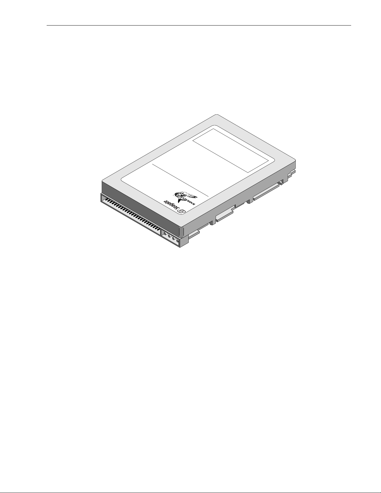
Figure 1. Barracuda 4XL family drive . . . . . . . . . . . . . . . . . . . . . . . . . . . . . . . . . . . . . . . . . . . . . . . . . . . 1
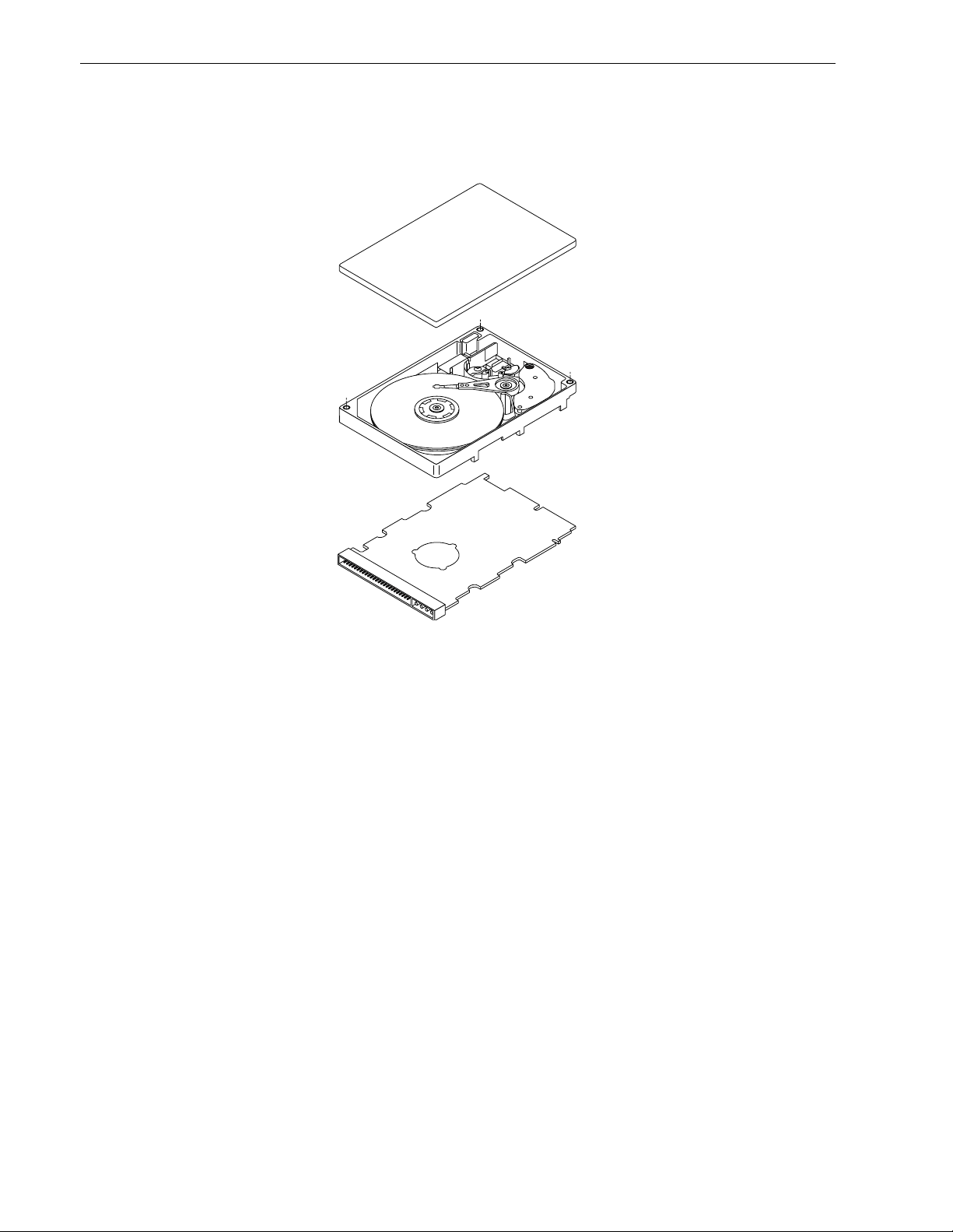
Figure 2. Barracuda 4XL family drive . . . . . . . . . . . . . . . . . . . . . . . . . . . . . . . . . . . . . . . . . . . . . . . . . . . 6
Figure 3. Typical Barracuda 4XL family drive +5 V and +12 V current profile. . . . . . . . . . . . . . . . . . . . 22
Figure 4. Locations of printed circuit board (PCB) components listed in Table 3 . . . . . . . . . . . . . . . . . 24
Figure 5. Recommended mounting . . . . . . . . . . . . . . . . . . . . . . . . . . . . . . . . . . . . . . . . . . . . . . . . . . . . 26
Figure 6. Mounting configuration dimensions for models “N” . . . . . . . . . . . . . . . . . . . . . . . . . . . . . . . . 28
Figure 7. Mounting configuration dimensions for models “W” and “WD”. . . . . . . . . . . . . . . . . . . . . . . . 29
Figure 8. Mounting configuration dimensions for models “WC” and “DC”. . . . . . . . . . . . . . . . . . . . . . . 30
Figure 9. Barracuda 4XL family drive ID select header for models “N” . . . . . . . . . . . . . . . . . . . . . . . . . 34
Figure 10. Barracuda 4XL family drive ID select for models “W,” “WC,” “WD,” and “DC”. . . . . . . . . . . . 35
Figure 11. Barracuda 4XL family drive ID select header J1-auxiliary for models “W” and “WD”
(J1-Auxiliary Pins 1A - 12A) . . . . . . . . . . . . . . . . . . . . . . . . . . . . . . . . . . . . . . . . . . . . . . . . . . 36
Figure 12. Barracuda 4XL family drive option select header for models “N,” “W,” and “WD” . . . . . . . . . 37
Figure 13. Barracuda 4XL family drive option select header for models “WC” and “DC” . . . . . . . . . . . . 37
Figure 14. Air flow (suggested) . . . . . . . . . . . . . . . . . . . . . . . . . . . . . . . . . . . . . . . . . . . . . . . . . . . . . . . . 41
Figure 15. Physical interface for “N” model drives. . . . . . . . . . . . . . . . . . . . . . . . . . . . . . . . . . . . . . . . . . 53
Figure 16. Physical interface for “W” and “WD” model drives . . . . . . . . . . . . . . . . . . . . . . . . . . . . . . . . . 54
Figure 17. Physical interface for “WC” and “DC” model drives . . . . . . . . . . . . . . . . . . . . . . . . . . . . . . . . 54
Figure 18. SCSI daisy-chain interface cabling for “N,” “W,” and “WD” model drives . . . . . . . . . . . . . . . . 58
Figure 19. Nonshielded 50 pin SCSI device connector used on “N” model drives . . . . . . . . . . . . . . . . . 59
Figure 20. Non-shielded 68 pin SCSI device connector used on “W” and “WD” model drives . . . . . . . . 60
Figure 21. Non-shielded 80 pin SCSI “SCA-2” connector, used on “WC” and “DC” model drives . . . . . 61
Figure 22. Single-ended transmitters and receivers . . . . . . . . . . . . . . . . . . . . . . . . . . . . . . . . . . . . . . . . 68
Figure 23. Typical differential I/O line transmitter/receiver and external terminators . . . . . . . . . . . . . . . 70
Page 10

Page 11
Barr acuda 4X L P roduct Manual, Rev. B 1
1.0 Scope
This manual describes the Seagate Technology®, Inc. Barracuda 4XL™ disc drives.
Barracuda 4XL drives suppor t the small computer system interface (SCSI) as describe d in the ANSI SCSI,
SCSI-2, and SCS I-3 (Fast-20) interface specifications to t he extent descr ibed in this manual. The
face Product Manual
other families of Seagate drives.
From this point on in this product manual the reference to Barracuda 4XL models is referred to as “the drive”
(unless references to individual models are necessary).
.
(part number 77738479) describes general SCSI interface characteristics of this and
SCSI Inter-
*
*Model “N” version with 50 pin SCSI I/O connector
Figure 1. Barracuda 4XL famil y drive
Page 12

Page 13

Barr acuda 4X L P roduct Manual, Rev. B 3
2.0 Applicable standards and reference documentation
The drive has been developed as a system peripheral to the highest standards of design and construction. The
drive depends upon its host eq uipment to provide adeq uate power and environment in order to a chieve optimum performance and c ompliance with applicable industry a nd governmental regulations. Special attention
must be given in the areas of safety, power distribution, shielding, audible noise control, and temperature regulation. In par ticular, the drive must be securely mo unte d in o rder to guarante e th e spec ified pe rformanc e characteristics. Mounting by bottom holes must meet the requirements of Section 8.4.
2.1 Standards
Barracuda 4XL family drives comply with Seagate standards as noted in the appropriate sections of this manual and the Seagate
Barracuda 4XL disc drives are UL recognized components per UL1950, CSA certified to CSA C22.2 No. 950M89, and VDE certified to VDE 0805 and EN 60950 .
2.1.1 Electromagnetic compatibility
The drive, as delivered, is designed f or system integration and installation into a suitable enclosure prior to use.
As such the drive is supplied as a subassembly and is not subject to Subpart B of Part 15 of the FCC Rules
and Regulations nor the Radio Interference Regulations of the Canadian Department of Communications.
The design characteristics of the drive serve to minimize radiation when installed in an enclosure that provides
reasonable shielding. As such, the drive is capable of meeting the Class B limits of the FCC Rules and Regulations of the Canadian Department of Communications when properly packaged. However, it is the user’s
responsibility to assure that the drive meets the appropriate EMI requirements in their system. Shielded I/O
cables may be required if the enclosure does not provide adequate shielding. If the I /O cables are external t o
the enclosure, shielded cables should be used, with the shields grounded to the enclosure and to the host controller.
SCSI Interface Product Manual
, part number 77738479 (Vol. 2).
2.1.2 Electromagnetic susceptibility
As a component assembly, the drive is not required to meet any susceptibility performance requirem ents. It is
the responsibility of those integrating the dri ve within their system s to perform thos e tes ts req uired a nd desig n
their system to ensure that equipm ent operating in the same system as the drive or external to the system
does not adversely affect the performance of the drive. See Section 5.1.1 and Table 2, DC power requirements.
2.2 Electromagnetic compliance
Seagate uses an independen t laboratory to confirm compliance to the directives/standard(s) for CE Marking
and C-Tick Marking. The drive was tested in a representative system for typical applications. The selected system represents the most popular characteristics for test platforms. The system configurations include:
• 486, Pentium, and PowerPC microprocessors
• 3.5-inch floppy disc drive
• Keyboard
• Monitor/display
• Printer
• External modem
•Mouse
Although the test system with this Seagate model complies to the directives/standard(s), we cannot guarantee
that all systems will comply. The computer manufacturer or system integrator shall confirm EMC compliance
and provide CE Marking and C-Tick Marking for their product.
Electromagnetic compliance for the European Union
If this model has the CE Marking it complies with the European Union requirements of the Electromagnet ic
Compatibility Directive 89/336/EEC of 03 May 1989 as amended by Directive 92/31/EEC of 28 April 1992 and
Directive 93/68/EEC of 22 July 1993.
Page 14

4 Barracud a 4X L Product Man ual, Rev. B
Australian C-Ti ck
If this model has the C-Tick Marking it complies with the Australia/New Zealand Standard AS/NZS3548 1995
and meets the Electromagnetic Compatibility (EMC) Framework requirements of Australia’s Spectrum Management Agency (SMA).
2.3 Reference documents
Barracuda 4XL Installation Guide: Seagate P/N 77767501
SCSI Interface Product Manual: Seagate P/N 77738479
ANSI Small Computer System Interface (SCSI): ANSI3.131-1986 (X3T9/84.40 Rev. 1B)
(X3T9.2/82-2 Rev. 17B), X3T9.2/86-109 Revision 10H (SCSI-2), X3T9.2/91/010 Rev. 10 (SCSI-3) parallel interface, X3T9.2-184 Rev. 4 (SCSI-3) and ANSI SCSI-3 Fast-20, X3T10/1071D.
Package Test Specification Seagate P/N 30190-001 (under 100 lb.)
Package Test Specification Seagate P/N 30191-001 (over 100 lb.)
Specification, Acoustic Test Requirements: Seagate P/N 30553-001
In case of conflict between this document and any referenced document, this document takes precedence.
Page 15
Barr acuda 4X L P roduct Manual, Rev. B 5
3.0 General description
Barracuda 4XL drives combine magnetoresistive (MR) heads, partial response/maximum likelihood (PRML)
read channel electronics, embedded servo technology, and a SCSI-3 (Fast-20) interface to provide high performance, high capacity data storage for a variety of systems including engineering workstations, network servers, mainframes, and supercomputers.
Fast-20 (also known as Ultra SCSI) is a negotiated transfer rate. This transfer rate will occur only if your host
adapter also supports Fast-20 data transfer rates. This drive also operates at SCSI-1 and SCSI-2 data transfer
rates for backward compatibility with non-Fast-20 capable SCSI host adapters.
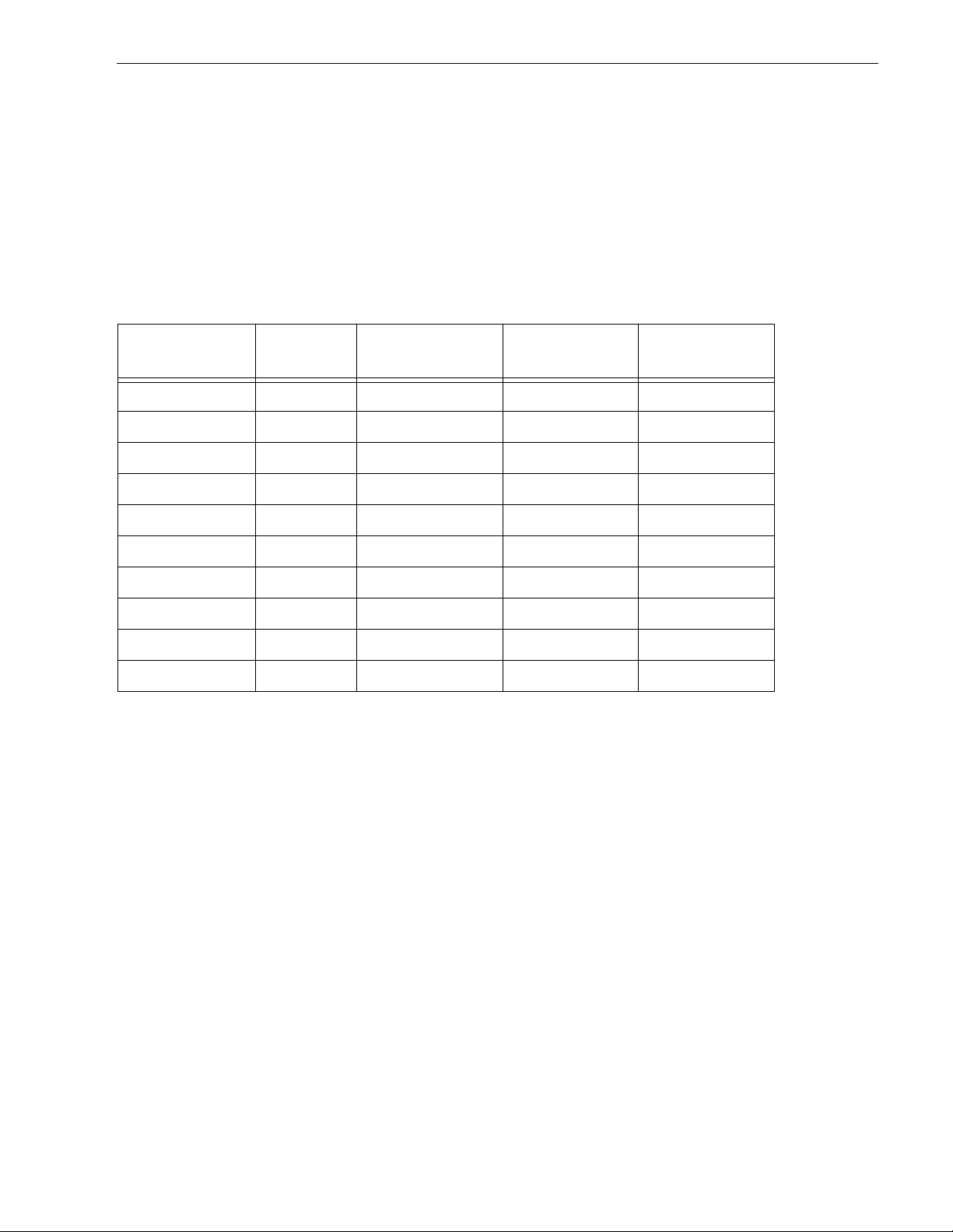
Table 1 lists the features that differentiate the various Barracuda 4XL SCSI-3 Fast-20 (Ultra SCSI) models.
Table 1: Drive model number vs. differentiating features
Number
Model number
ST34572N 8 single-ended 50 8
ST34572W 8 single-ended 68 16
ST34572WD 8 differential 68 16
ST34572WC 8 single-ended 80 16
ST34572DC 8 differential 80 16
ST32272N 4 single-ended 50 8
ST32272W 4 single-ended 68 16
ST32272WD 4 differential 68 16
ST32272WC 4 single-ended 80 16
ST32272DC 4 differential 80 16
The drive records and recovers data on 3.5-inch (86 mm) non-removeable discs.
The drive suppor ts the Small Computer System Interface (SCSI) as describ ed in the ANSI SCSI-2 interface
specifications to the extent described in this manual (volume 1), which defines the product perform ance characteristics of the Barracuda 4XL family of drives, and the
ber 77738479, which describes the general interface characteristics of this and other families of Seagate SCSI
drives.
of heads I/O circuit type
Number of I/O
connector pins
Number of I/O
data bus bits
SCSI Interface Product Manual
(volume 2), part num-
The drive’s interface supports multiple initiators, disconnect/reconnect, self-configuring host software, and
automatic features that relieve the host from the necessity of knowing the physical characteristics of the targets
(logical block addressing is used).
The head and disc assembly (HDA) is sealed at the factory. Air circulates within the HDA through a nonreplaceable filter to maintain a contamination-free HDA environment.
Refer to Figure 2 for an exploded view of the drive. This exploded view is for information only—never disassemble the HDA and do not attempt to service items in the sealed enclosure (heads, med ia, actuator, etc.) as this
requires special facilities. The drive contains no replaceable parts. Opening the HDA voids your warranty.
Barracuda 4XL drives use a dedic ated landi ng zone at the innermost radius of the me dia to eli minat e the pos sibility of destroying or degrading data by landing in the data zone. The drive automatically goes to the landing
zone when power is removed.
An automatic shipping lock prevents potential damage to the heads and discs that results from movement during shipping and handling. The shipping lock automatical ly disenga ges when power is appli ed to the drive and
the head load process begins.
Page 16
6 Barracud a 4X L Product Man ual, Rev. B
Barracuda 4XL drives decode track 0 location data from the servo data embedded on each surface to eliminate
mechanical transducer adjust m ents and re lated r eliability concerns.
A high-performance actuator ass embly with a low-inertia, balanced, pa tented, straight-arm design provides
excellent performance with minimal power dissipation.
Figure 2. Barracuda 4XL famil y drive
Page 17

Barr acuda 4X L P roduct Manual, Rev. B 7
3.1 Standard features
The Barracuda 4XL family has the following standard features:
• Integrated SCSI controller
• Single-ended and differential SCSI drivers and receivers
• 8 bit and 16 bit I/O data bus models available
• Asynchronous and synchronous data transfer protocol
• Firmware downloadable via SCSI interface
• Selectable even byte sector sizes from 180 to 4,096 bytes/sector
• Programmable drive capacity
• Programmable sector reallocation scheme
• Flawed sector reallocation at format time
• Programmable auto write and read reallocation
• Reallocation of defects on command (Post format)
• 128-bit Reed-Solomon error correcting code
• Sealed head and disc assembly
• No preventative maintenance or adjustment required
• Dedicated laser textured head landing zone
• Embedded servo data rather than a separate servo data surface
• Self diagnostics performed when power is applied to the drive
• 1:1 Interleave
• Zoned bit recording (ZBR)
• Vertical, horizontal, or top down mounting
• Dynamic spindle brake
• Active IC terminators enabled by jumpers (“N” and “W” models only)
• 512 K byte data buffer
• Hot plug compatibility (section 9.6.4.3 lists the proper host connector needed) for “WC” and “DC” drives
• SCAM (SCSI Configured AutoMagically) plug-n-play level 2 compliant
• Low audible noise for office environment
• Low power consumption
• Audio Visual (A/V) ready
3.2 Media characteristics
The media used on the drive has a diameter of approximately 3.5 inches (86 mm). The aluminum substrate is
coated wi th a thin film mag net ic mat eria l, overcoat ed wit h a prop rie tar y pro tective layer for improved d urabilit y
and environmental protection.
3.3 Performance
• Supports industry standard Ultra SCSI interface (also called “Fast -20 SCSI”)
• Programmable multi-segmentable cache buffer
• 7200 RPM spindle. Average latency = 4.17 ms
• Command queuing of up to 64 commands
• Background processing of queue
• Supports start and stop commands (spindle stops spinning)
3.4 Reliability
• 1,000,000 hour MTBF
• LSI circuitry
• Balanced low mass rotary voice coil actuator
• Incorporates industr y -standa rd Self-Monit orin g, Analysis and Reporting Technology (S.M.A.R.T.)
• Incorporates Seek To Improve Reliability algor ithm (STIR )
• 5-year warranty
Page 18

8 Barracud a 4X L Product Man ual, Rev. B
3.5 Unformatted and formatted capacities
Formatted capacity depends on the number of spare reallocation sectors reserved and the number of bytes per
sector. The following table sho ws the st andard OEM model read capacity data. Total LBAs = read capacity data
shown below + 1.
Formatted [1]
data block size
Model
ST34572 87A25Bh (4.55 GB) 6.5 GB 118 spares per six cylinder region
ST32272 436F87h (2.26 GB) 3.25 GB 59 spares per six cylinder region
Notes.
[1] Sector size selectable at format time. Users having the necessary equipment may modify the data block
size before issuing a format command and ob tain different formatted capacities than those listed. User
available capacity depends on spare reallocation scheme selected. See Mo de S elect Comm and a nd Format Command in the
3.6 Programmable drive capacity
Using the Mode Select command, the drive can change its capacity to something less than maximum. See
Table 5.2.1-13 in the
descriptor, bytes 1, 2 and 3. A value of zero in bytes 1 , 2 and 3 indicat es that the drive shall not change the
capacity it is currently formatted to have. A number in bytes 1, 2 and 3 that is less than the maximum number of
LBAs changes the total drive capacity to the value in the block descriptor bytes 1, 2 and 3. A value greater than
the maximum number of LBAs is rounded down to the maximum capacity .
512 byte/sector Unformatted Sparing
SCSI Interface Product Manual
SCSI Interface Product Manual
(part number 77738479).
(part number 77738479). Refer to the Parameter list bl oc k
3.7 Factory installed accessories
OEM Standard drives are shipped with
erwise specified. The factory also ships with the drive a small bag of the two jumper plug types used for the J6,
J2, and J1-Aux option select jumper headers.
3.8 Options (factory installed)
All customer request ed options are incor porated during prod uction or packaged at the manufactur ing facility
before shipping. Some of the options available are:
• The capacities shown in Section 3.5. You can order other capacities by selecting other sparing schemes and
sector sizes.
• Single unit shipping pack. The drive normally ships in bulk packaging to provide maximum protection against
transit damage. Units shipped ind ividually require additional p rotection as provided by the s ingle unit shipping pack. Specify this option if you are planning to ship single units to your customers.
• The
3.9 Accessories (user installed)
The following accessories are available. Qualified individuals can install these accessories in the field.
• Front panel kit (with green rectangular LED lens), part number 73501451.
• Single unit shipping pack.
•
Barracuda 4XL Installation Guide
drive. You may order additional copies of this publication.
Barracuda 4XL Installation Guide
Barracuda 4XL Installation Guide
(part number 777 67501) i s u sually in cluded wi th e ach s tandard OE M
(part number 77767501).
(part num ber 77767501) unless oth-
Page 19

Barr acuda 4X L P roduct Manual, Rev. B 9
4.0 Perfo rmance characteristics
4.1 Internal drive characteristics (transparent to user)
ST34572 ST32272
Drive Capacity 6.5 3.25 GByte (unformatted)
Read/Write Heads 8 4
Bytes/Track 124,000 124,000 Bytes (average, unformatted)
Bytes/Surface 812.5 812 .5 Mbytes (unformatted)
Tracks/Surface, Total 6,311 6,311 Tracks (user accessible)
Tracks/Inch 6,800 6,800 TPI
Peak Bits/Inch 139,209 139,209 BPI
Internal Data Rate 92-140 92-140 Mbits/sec (variable with zone)
Disc Rotational Speed 7,200 7,200 r/min
Average Rotational Latency 4.17 4.17 ms
4.2 SCSI Seek performance characteristics (visible to user) [6]*
The values given in Section 4.2.1 apply to all models o f the Barracuda 4XL family unless otherwise s pecified.
Refer to Section 9.10 and to the
details.
SCSI Interface Product Manual
(part number 77738479 ) for additional timing
4.2.1 Access time [8]
Including Controller Overhead
(without disconnect) [1] [4]
Drive Level
Read Write
ms
Average – Typical [3] 9.4 10.4
Maximum [2] 10.8 11.9
Single Track – Typical [3] 1.7 1.8
Maximum [2] 1.8 1.9
Full Stroke – Typical [ 3] 16.7 17.7
Maximum [2] 19.7 20.2
*[ ] All notes for Section 4.2 are listed at end of Section 4.2.3.
Page 20

10 Barracuda 4XL Product Manual, Rev. B
4.2.2 Format command execution time (minutes) [1]*
ST34572 ST32272
Maxim um (with verif y) 95 50
Maximum (no verify) 65 35
4.2.3 Generalized performance characteristics
Minimum sector interleave 1 to 1
Data buffer transfer rate to/from disc media (one 512-byte sector):
Min. [4]* 11.5 MByte/sec
Avg. [4] 15.5 MByte/sec
Max. [4] 17.5 MByte/sec
Data buffer transfer rate to/from disc media: (< 1 track):
Min. [4] 7.86 MB yte/sec divided by (interleave factor)
Avg. [4] 11.0 MB yte/sec divided by (interleave factor)
Max. [4] 12.5 MByte/sec divided by (interleave factor)
SCSI interface data transfer rate (asynchronous) [5]:
Maximum instantaneous 6.0 Mbytes/sec [6]
Maximum average 6.0 Mbytes/sec [7]
Synchronous transfer rate for SCSI Fast-20 (Ultra SCSI): 1.25 to 20 Mbytes/sec
(8 bit data bus models)
Synchronous transfer rate for SCSI Fast-20 (Ultra SCSI): 2.5 to 40 Mbytes/sec
(16 bit data bus models)
Synchronous transfer rate for fast SCSI-2: 1.25 to 10 Mbytes/sec
(8 bit data bus models)
Synchronous transfer rate for fast SCSI-2: 2.5 to 20 Mbytes/sec
(16 bit data bus models).
Secto r Sizes:
Default 512 byte user data blocks
Var iable 180 to 4,096 bytes per sector in even number
of bytes per sector.
If n (number of bytes per sector) is odd, then
n-1 will be us ed .
Read/write consecutive sectors on a track Yes
Flaw reallocation performance impact (for flaws reallocated at format time using
Negligible
the spare sectors per sparing region reallocation scheme.)
Overhead time for head switch (512 byte sectors) in sequential mode 1 msec
Overhead time for one track cylinder switch in sequential mode <2.4 msec (typical)
Average rotational latency 4.17 msec
*[] Notes listed at end of Section 4.2.3.
Page 21

Barr acuda 4X L P roduct Manual, Rev. B 11
Notes for Section 4.2.
[1] Execution time is measured from receipt of the last Byte of the Command Desc riptor Block (CDB) to th e
request for a Status Byte Tr ansf er to the Initiator (excluding connect/disconnect).
[2] Maximum times are specified over the worst case conditions of temperature, voltage margins and dr ive
orientation. When comparing spec ified access times, care should be taken to distinguish between typical
access times and maximum access times. The best comparison is obtained by system benchmark tests
conducted under identical conditions. Maximum times do not include error recovery.
[3] Typical acce ss times are meas ured under nom inal conditions of temperat ure, voltage, and horizontal ori-
entation as measured on a representative sample of drives.
[4] Assumes no errors and no sector has been relocated.
[5] Rate measured from the start of the first sector transfer to or from the host.
[6] Assumes system ability to support the rates listed and no cable loss.
[7] Simulated.
[8] Access time = controller overhead + average seek time
Access to data = controller overhead + average seek time + latency time
4.3 Start/stop time
After DC power at nominal voltage has been applied, the drive becomes ready within 20 seconds if the Motor
Start Option is disabled (i.e. the motor starts as soon as the power has been applied). If a recoverable error
condition is detected during the star t sequence, the drive executes a recovery procedure which may cause the
time to become ready to exceed 20 seconds. During spin up to read y time the drive responds to some commands over the SCSI interface in less than 3 seconds after application of power. Stop time is less than 20 seconds from removal of DC power.
If the Motor Start Option is enabled, the internal cont roller accepts the comm ands listed in the SC SI Interface
Product Manual less than 3 seconds after DC power has been applied. After the Motor Start Command has
been received the drive becomes ready for normal operations within 13 seconds typically (excluding an error
recovery procedure). The Motor Start Command can also be used to command the drive to stop the spindle
SCSI Interface Product Manual
(see
There is no power control switch on the drive.
4.4 Prefetch/multi-segmented cache control
The drive provides prefetch (read look-ahead) and multi-segmented cache control algorithms that in many
cases can enhance system performance. “Cache” as used herein refers to the drive bu ffer storage space when
it is used in “cache” operat ions. To sele ct prefetch and cache features the hos t sends the Mo de Select command with the proper values in the a pplicable bytes in Mode Page 08h (see
part number 77738479). Prefetch and cache operation are independent features from the standpoint that each
is enabled and disabled independently via the Mode Select command. However, in actual operation the
prefetch feature overlaps cache operation somewhat as is noted in Section 4.5.1 and 4.5.2.
All default cache and prefetch Mode parameter values (Mode Page 08h) for standard OEM versions of t his
drive family are given in Tables 8 and 9.
4.5 Cache operation
In general, 480 Kbytes of the 512 Kbytes of physical buffer space in the drive can be used as storage space for
cache operations. The buffer can be divided into logical segments (Mode Select Page 08h, byte 13) from which
data is read and to which data is written. The drive maintains a table of logical block disk medium addresses of
the data stored in each segment of the buffer. If cache operation is enabled (RCD bit = 0 in Mode Page 08h,
byte 2, bit 0. See
Read command is retrieved from the buffer (if it is there), before any disc access is initiated. If cache operation
is not enabled, the buffer (still seg mented with required number of segm ents) is s till used, but onl y as circu lar
buffer segments during disc medium read operations (disregarding Prefetch operation for the moment). That is,
the drive does not check in the buffer segments for the requested read data, but goes directly to the medium to
retrieve it. The retrieved data merely passes through som e buffer segment on the way to the host. On a cache
SCSI Interface Product Manual
, part number 77738479).
SCSI Interface Product Manual
(par t number 7773847 9), data request ed by the ho st with a
,
Page 22

12 Barracuda 4XL Product Manual, Rev. B
“miss”, all data transfers to the host are in accordance with “buffer-full” ratio rules. On a cache “hit” the drive
ignores the “buffer-full” ratio rules. See explanations associated with Mode page 02h (disconnect/reconnect
control) in the
The following is a simplified description of a read operation with cache operation enabled:
Case A - A Read command is received and the first logical block (LB) is already in cache:
1. Drive transfers to the initiator the first LB requested plus all subsequent contiguous LB’s that are already in
the cache. This data may be in multiple segments.
2. When the requested LB is reached that is not in any cache segment, the drive fetches it and any remaining
requested LBs from the di sc and puts them in a segment of the cache. The drive transfers the rem aining
requested LBs from th e cac he to the hos t in accorda nc e with t he disconnec t /reconn ect spe cification m entioned above.
3. If the prefetch feature is enabled, refer to Section 4.5.2 for operation from this point.
Case B - A Read command requests data, the first LB of which is not in any segment of the cache:
1. The d rive fetches the requested LB’s from the disc and transfers them into a segment, and from t here to
the host in accordance with the disconnect/reconnect specification referred to in case A.
2. If the prefetch feature is enabled, refer to Section 4.5.2 for operation from this point.
Each buffer segment is actually a self-contained circular storage (wrap-around occurs), the length of which is
an integer number of disc medium sectors. The wrap-around capability of the individual segments greatly
enhances the buffer’s ov erall performance as a cache storage, allowing a wide range of user selectable configurations, which includes their use in the prefe tch operation (if enabled), even when cache operation is disabled
(see Section 4.5.2). The number of segm ents may be selected using the M ode Select com mand, but the size
can not be directly selected. Size is selected only as a by-product of selecting the segment number specification. The size in Kbytes of each segment is reported by the Mode Sense command page 08h, bytes 14 and 15.
If a size specification is sent by the host in a Mode Select command (bytes 14 and 15) no new segment size is
set up by the drive, and if the “STRICT” bit in Mode page 00h (byte 2, bit 1) is set to one, the drive responds as
it does for any attempt to change unchangeable parameters (see
77738479). The drive supports operation of any integer number of segments from 1 to 16.
SCSI Interface Product Manual
(part number 77738479).
SCSI Interface Product Manual
, part number
4.5.1 Caching write data
Write caching is a write operation by the d rive tha t makes use of a d r ive buffer storage area where the dat a t o
be written to the medium is stored in one or more segments while the drive performs the write command.
Write caching is enabled along w ith read c aching. For write caching, the s am e buffer space and segment ation
is used as set up for read functions. The buffer segmentation scheme is set up or changed independently , having nothing to do with whether or not read and write caching is enabled or disabled. When a write command is
issued, the cache is first checked to see if any logical blocks that are to be written are already stored in the
cache from a previous read or write com mand. If there are, the re spective cache segments are c leared. The
new data is cached for subsequent Read commands.
If the number of write data logical blocks exceeds the size of the segment being written into when the end of
the segment is reached, the data is written into the beginning of the same cache segment, overwriting the data
that was written there at the beginning of the operation. Howev er, the drive does not overwrite data that has not
yet been written to the medium.
Tables 8 and 9 show Mode default settings for the drives.
4.5.2 Prefetch operation
If the Prefetch feature is enabled, data i n cont igu ous lo gical blocks on the disc imm edi ately beyond that which
was requested by a Read command can be retrieved and stored in the buffer for immediate transfer from the
buffer to the host on subsequent Read comm and s that request those logical blocks (this is true even if “cache”
operation is disabled). Though the prefetch operation uses the buffer as a “cache”, finding the requested data
in the buffer is a prefet ch “hit”, not a “cache” operation “hit”. Prefetch is enabled using Mode Select page 08h,
byte 12, bit 5 (Disable Read Ahead - DRA bit). DRA bit = 0 enables prefetch. Since data that is prefetched
replaces data already in some buffer segment(s), the host c an limit the amount of prefetch data to optimize
Page 23

Barr acuda 4X L P roduct Manual, Rev. B 13
system performance. The max prefetch field (bytes 8 and 9) limits the am ount of prefetch. The drive does not
use the prefetch “ceiling” field (bytes 10 and 11).
During a prefetch operation, the drive crosses a cylinder bo undary to fetch more data only if the Discont inuity
(DISC) bit is set to one in bit 4 of byte 2 of Mode parameters page 08h.
Whenever prefetch (read look-ahead) is enabled (enabled by DRA = 0), it operates under the control of ARLA
(Adaptive Read Look-Ahead). If the host uses software interleave, ARLA enables prefetch of contiguous blocks
from the disc when it senses t hat a prefetch “hit” will likely occur, even if two consecutive read operations were
not for phy si cally contiguous blocks of data (e.g. “software interleave”). ARLA disables prefetch when it decides
that a prefetch “hit” will not likely occur. If the host is not using software interleave, and if two seque ntial read
operations are not for contiguous blocks of data, ARLA disables prefetch, but as long as sequential read operations request contiguous blocks of data, ARLA keeps prefetch enabled.
Page 24

Page 25

Barr acuda 4X L P roduct Manual, Rev. B 15
5.0 Reliability specifications
The following reliabilit y specifications assume correct host/dri ve operational interface, including all interface
timings, power supply voltages, environmental requirements and drive mounting constraints (see Section 8.4).
Seek Errors
Less than 1 in 10
Read Error Rates [1]
Recovered Data Less than 10 errors in 10
Unrecovered Data Less tha n 1 sector in 10
Miscorrected Data Less than 1 sector in 10
MTBF 1,000,000 hours
Service Life 5 years
Preventive Maintenance None required
Note.
[1] Error rate specified with automatic retries and data correction with ECC enabled and all flaws reallocated.
5.1 Error rates
The error rates stated in this specification assume the following:
• The drive is operated per this specification using DC power as defined in this manual (see Section 6.2).
• The drive has been formatted with the SCSI FORMAT commands.
• Errors caused by media defects or host system failures are excluded from error rate computations.
7
seeks
11
bits transferred (default settings)
14
bits transferred (default settings)
21
bits transferre d
5.1.1 Environmental interference
When evaluating systems operation under conditions of Electromagnetic Interference (EMI), the performance
of the drive within the system shall be c onsidered acce ptable if the drive does not generate a n unrecoverable
condition.
An unrecoverable error, or unrecoverable condition, is defined as one that:
• Is not detected and corrected by the drive itself;
• Is not capable of being detected from the error or f ault status provided through the drive or SCSI interface; or
• Is not capable of being recovered by normal drive or system recovery procedures without operator intervention.
5.1.2 Read errors
Before determination or measurement of read error rates:
• The data that is to be used for measurement of read error rates must be verified as being written correctly on
the m edia.
• All media defect induced errors must be excluded from error rate calculations.
5.1.3 Write erro rs
Write errors can occur a s a result of media defects, environmental interference, or equipment malfunction.
Therefore, write errors are not predictable as a function of the number of bits passed.
If a write error unrecoverable occurs because of an equipment malfunction in the drive, the error is classified as
a failure affecting MTBF. Unrecoverable write errors are those which cannot be corrected within two attempts at
writing the record with a read verify after each attempt (excluding media defects).
Page 26

16 Barracuda 4XL Product Manual, Rev. B
5.1.4 Seek errors
A seek error is defined as a failure of the drive to position the heads to the address ed tra ck. There shall be no
8
more than ten recoverable seek errors in 10
physical seek operations. After detecting an initial seek error, the
drive automatically reseeks to the addressed track up to 3 times. If a reseek is successful, the Extended Sense
reports a s eek pos itioning error (15h), no seek compl ete error (02h), or t rack follow error (09h), and the sens e
key reports a recovered error (1h). If all three reseeks fail, a seek positioning error (15h) is repor ted with a
Medium error (3h) or Hardware error (4h) reported in the Sense Key. This is an unrecoverable seek error. Unrecoverable seek errors are classified as failures for MTBF calculations. Refer to Section 5.1.1.2 of the
Interface Product Manual
(part number 77738479) for Request Sense information.
SCSI
5.2 Reliability and service
You can enhance the reliability of Barracuda 4XL disc drives by ensuring that the drive receives adequate cooling. Section 6.4.1 provides temperature measurements and other information that may be used to enhance the
service life of the drive. Section 8.3.1 provides recommended air-flow information.
5.2.1 Mean time between failure
The production disc dri ve shall achieve an MTBF of 1,000,000 hours w hen operated in an environment that
ensures the case temperatures spec ified in Section 6.4.1 are not exceeded. Shor t-term excursions up to the
specification limits of the operating environment will not affect MTBF performance.
The following expression defines MTBF
Estimated power-on operating hours in the period
MTBF per measurement period =
Number of drive failures in the period
Estimated power-on operation hours means power-up hours per disc drive times the total number of disc drives
in service. Each disc drive shall have accumulated at least nine months of operation. Data shall be calculated
on a rolling average base for a minimum period of six months.
Drive failure means any stoppage or substandard performance caused by drive malfunction.
5.2.2 Preventive maintenance
No routine scheduled preventive maintenance shall be required.
5.2.3 Service life
The drive shall have a useful service life of five years. Depot repair or replacement of major parts is permitted
during the lifetime (see Section 5.2.4).
5.2.4 Servi c e philosophy
Special equipment is required to repair the drive HDA. In order to achieve the above service life, repairs must
be performed only at a properly equipped and s taffed service and r epair facility. Trou bleshooting and repair of
PCBs in the field is not rec ommended, because of the extensive diagnost ic equipment required for effective
servicing. Also, there are no spare parts available for this drive. Drive warranty is voided if the HDA is opened.
5.2.5 Service tools
No special tools are required for site installation or recommended for site maintenance. Refer to Section 5.2.4.
The depot repair philosophy of the drive precludes the necessity for special tools. Field repair of the drive is not
practical since there are no user purchasable parts in the drive.
Page 27

Barr acuda 4X L P roduct Manual, Rev. B 17
5.2.6 Hot plugging Barracuda 4XL disc drives Caution: Hot -plug drives are not designed for simultaneous power disconnection and physical removal.
During power-up and power-down periods, the hot SCSI connect/disconnect capability does not produce
glitches or any corruptions on an active SCSI bus. Barracuda 4XL drives conform to the SCSI-3 standard
requirements for glitch-free power-on and power-off. The drive maintains the high-impedance state at the
device connector contacts during a power cycle until the transceiver is enabled.
Note. The s ystems integrator mus t ensure that no tempe rature, energy, or voltage hazard is presented dur-
ing the hot connect/disconnect operation.
Procedure:
1. Conf igure the drive with no connection between the drive and the TRMPWR signal on the SCSI bus. To
accomplish this, remove all jumpers from connector J2 pins 1, 2, 3, and 4.
2. Ensure that all SCSI devices on the bus have receivers that conform to the SCSI-3 standard.
3. Eliminate all I/O processes for the drive.
4. Wait until the drive motor and discs have come to a complete stop prior to changing the plane of operation,
ensuring data integrity.
5. Insert or remove the drive after meeting the following conditions:
Caution: Do not hot-plug th e first or last device on the SCSI bus (the SCSI bus termination must be external
to the drive you are inserting or removing).
a. If you are inse rt ing the dr ive, connect its power ground and logic ground at least 1 millisecon d before
coming into contact with t he bus connector. Maintain these ground connections d uring and after connecting the device to the bus.
b. If you are removing the device, maintain its power ground and logic ground connection for at least
1 millisecond after disconnecting the device from the bus.
c. You may simultaneously switch the power to the el ectronics and mechani cs of the drive with the bus
contacts, if the power distribution system is able to maintain adequate power stability to other devices
during the transition and if you have met the grounding requirements given in steps 5a and 5b.
d. Ensure that the drive carrier discharges all static e lectricity prior to inserting the drive into the system .
Note. Do not remove or add terminator power or resistance to the SCSI bus while hot plugging a disc drive.
5.2.7 S.M.A.R.T.
S.M.A.R.T. is an acronym for Self-Monitor ing Analysis and Re por ting Technology. This t echnology is intended
to recognize conditions that indicat e immine nt drive failure, and provide sufficient warn ing of a failure to allow
data back-up.
Note. The firmware will monitor spe cific attributes for degradation over time but can ’t predict instantan eous
drive failures.
Each attribute has been selected to mo nitor a spec ific set of failure conditions in the operat ing pe rformanc e of
the drive, and the thresholds are optimized to minimize “false” and “failed” predictions.
Controlling S.M.A.R.T.
The operating mode of SMART is controlled by the DEXCPT bit and the PER F bit of the “Inform ational Exc eptions Control Page” (1Ch). The DEXCP T bit is used to en able or disable the S.M.A.R.T. process. Setting the
DEXCPT bit will disable all S.M.A.R.T. functions. When enabled, S.M.A.R.T . will collect on-line data as the drive
performs normal read/write operation s. When the PERF bit is set, the drive is considered to be in “On-line
Mode Only” and will not perform off-line func tions.
The process of measuring off-line attributes and saving data can be forced by the RTZ command. Forcing
S.M.A.R.T. will reset the timer so that the next scheduled interrupt will be two hours.
The drive can be interrogated by the host to determine the time remaining before the next scheduled measurement and data logging process will occur. This is accomplished by a log sense command to log page 0x3E.
Page 28

18 Barracuda 4XL Product Manual, Rev. B
The purpose is to allow the customer to control when S.M.A.R.T. interruptions occur. As described above, forcing S.M.A.R.T. by the RTZ command will reset the timer.
Performance impact
S.M.A.R.T. attribute data is saved to the disc for the purpose of recreating the events that caused a predictive
failure. The drive measures and saves parameters once every two hours subject to an idle period o n the SCS I
bus. The process of measuring off-line attribute data and saving data to the disc is uninterruptable. The maximum delay is summarized below.
Maximum processing delay
On-line only del ay Fully enab le d delay
S.M.A.R.T. delay times 60 milliseconds 450 milliseconds
Repor tin g c on t rol
Reporting is controlled in the “Informational Exceptions Control Page” (1Ch). Subject to the reporting method,
the firmware will issue to the “hos t” an 01-5D00 sense code with the following FRU values returned by the
Request Sense command when a predict ive failure threshold is reache d. The error code is preserved through
bus resets and power cycles.
Predictive failure FRU codes
Attribute FRU code Predictive failure description
LBA reassignment 04 (01-5D04) LBA reassignment exceeding limits
Seek errors 43 (01-5D43) Seek error rate exceeding limits
Spinup errors 5B (01-5D5B) Spinup retry count exceeding limits
General failure EF (01-5DEF) Missing S.M.A.R.T. control information
Reassignment. When a reassignment (reallocation) is performed, the code determines the percentage of
entries still available in the Reallocation Table (RTB). If the pe rcentage of entries left falls below a predetermined threshold value, a predictive fa ilure is signaled .
Seek errors. Seek error rates are estimated on a per-head basis. For every seek, a seek interval counter is
incremented and for every seek error a seek failure counter is incremented. If the seek error rate exceeds a
predetermined threshold, the Seek Failure History counter is decremented (minimum value of zero). If the seek
error rate is below a predetermined threshold, the Seek Failure History counter is incremented. Whenever a
seek failure history count er changes, the corresponding Seek I nterval counter and the seek failure counters
are reset to zero, and a smoothing algorithm is performed. The fir mware checks the Seek Failure counter for
each head to determine the Seek Failure History counter with the largest value. The firmware will issue predictive failure if any single seek failure history counter has reached a predete rm in ed threshol d value.
Spinup errors. This attribute measures the “actuator buzz rate,” the number of actuator buzzes versus the
number of drive spinups. If a drive fails to spinup using a normal spinup routine, if issues a level 1 and then
level 3 actuator buzz to overcome drive stiction. For every spinup a spinup interval counter is incremented. If
the servo firmware issues a level 1 or a level 3 actuator buzz command, the Spinup Failure counter adds a 1 or
a 3 respectively. If the actuator buzz rate is below a predetermined threshold, the Spinup Failure History
counter is decremented (minimum value of zero). If the actuator buzz rate is above a predetermined threshold,
the Spinup Failure History counter is incremented.
When the Spinup Failure History counter changes, the S pinup Interval and the Spinup Failure counters are
reset to zero and a smoothing algorithm is performed. The drive issues a predictive failure if the Spinup Failure
History counter has reached a predetermined threshold value.
5.2.8 Product warranty
Beginning on the date of shipment to customer and continuing for a period of five years, Seagate warrants that
each product (including components and subassemblies) or spare part that fails to function properly under normal use due to defect in materials on workmanship or due to nonconformance to the applicable specifications
will be repaired or replaced, at Sea gate’s option and at no charge to customer, if returned by customer at customer’s expense to Seagate’s designated facility in accordance with Seagate’s Warranty Procedure. Seagate
will pay for transporting the rep air or replacement item to customer. For more detailed warranty information
refer to the Standard terms and conditions of Purchase for Seagate products.
Page 29

Barr acuda 4X L P roduct Manual, Rev. B 19
Shipping
When transpor ting or shipping a drive, a Seagate approved container must be us ed. Keep your original box.
They are easily identified by the Seagate App roved Packag e label. Shipping a drive in a non-approved container voids the drive warranty .
Seagate repair centers may refuse receip t o f components improperly packaged or obviously dam aged in transit. Contact your Authorized Seagate Distributor to purchase additional boxes. Seagate recommends shipping
by an air-ride carrier experienced in handling computer equipment.
Product repair and return information
Seagate customer service cente rs are the only facilities authorized to service Seagate drives. Seagate does
not sanction any third-party repair facilities. Any unauthorized repair or tampering with the factory-seal voids
the warranty. See Section 10.0.
Page 30

Page 31
Barr acuda 4X L P roduct Manual, Rev. B 21
6.0 Physical/electrical specifications
This section provides information relating to the physical and electrical characteristics of Barracuda 4XL drives.
6.1 AC power requirements
None.
6.2 DC power requirements
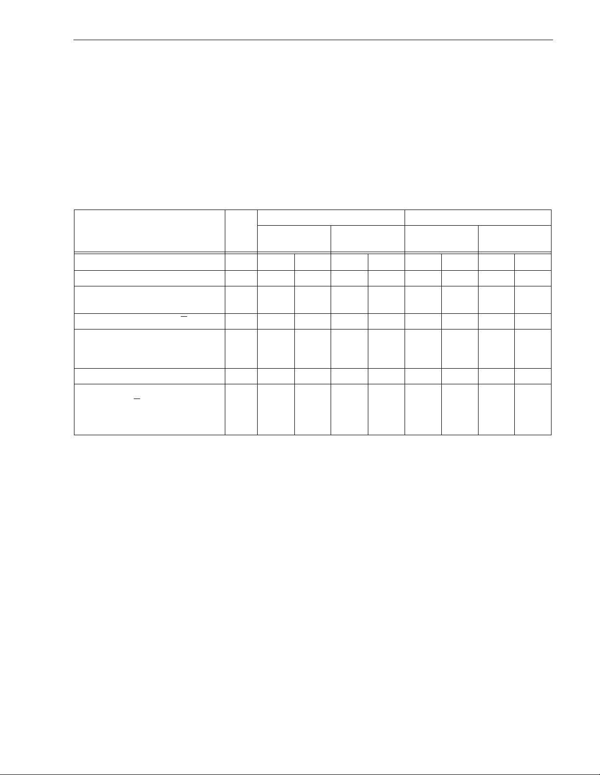
The voltage and current requirements for a single drive are shown in the following table. Values indicated apply
at the drive power connector. The single ended power requirements includes the internal disc drive SCSI I/O
termination. The table shows current values in Amperes.
Table 2: DC power requirements
ST34572 ST32272
N/W/WC
Notes
Vol tage +5 V +12 V +5 V +12 V +5 V +12 V +5 V +12 V
Regulation [5] ±5% ±5%[2] ±5% ±5%[2] ±5% ±5%[2] ±5% ±5%[2]
Maximum operating current
DC3σ [1] 0.81 0.95 1.21 0.95 0.81 0.85 1.21 0.85
Average idle current DCX
Maximum starti ng current
(peak DC) DC3σ
(peak AC) AC3σ
Delayed motor start (max) DC3σ [1][4] 0.48 0.20 0.90 0.20 0.50 0. 20 0.90 0.20
Peak operating current
Typical DCX
Maxim um DC3σ
Maxim um (P eak) 3σ
[1] 0.46 0.54 0.70 0.54 0.46 0.52 0.70 0.52
[3]
[3]
[1][6]
[1]
Single-e nded
0.78 2.44
3.1
0.75
0.81
1.5
0.76
0.95
2.5
WD/DC
Differential
1.1 2.44
3.1
1.05
1.21
2.0
0.76
0.95
2.5
N/W/WC
Single-e nded
0.78 2.00
3.1
0.72
0.81
1.5
0.73
0.85
2.3
WD/DC
Differential
1.1 2.00
3.1
0.91
1.21
2.0
0.73
0.85
2.3
Notes.
[1] Measured with average reading DC ammeter. Instantaneous +12 V current peaks will exceed these val-
ues.
[2] A –10% droop is per missible during initial start of s pindle, and must return to ±5% before 7,200 rpm is
reached. The ±5% must be maintained after the drive signifies that its power-up sequence has been com-
pleted and that the drive is able to accept selection by the host initiator.
[3] See +12 V current profile in Figure 3.
[4] This condition occurs when the Motor Star t Option is enabled and the drive has not yet received a Start
Motor co mmand.
[5] See Section 6.2.1 “Conducted Noise Immunity.” S pecified voltage tolerance is inclusive of ripple, noise,
and transient response.
[6] Operating condition is defined as random seek read operations with a block count of 64.
General Notes from Table 2:
1. Mi nimum current loading for each supply voltage is not less than 4% of the maximum operating current
shown.
2. The +5 and +12 volt supplies shall employ separate ground returns.
3. Where power is provided to multiple drives from a common supply, careful consideration for individual drive
power requirements should be noted. Where multiple units are powered on simultaneously, the peak starting current must be available to each device.
Page 32
22 Barracuda 4XL Product Manual, Rev. B
6.2.1 Conducted noise immunity
Noise is specified as a peri odic and random distribution of frequenc ies covering a band from DC t o 10 mHz.
Maximum allowed noise values given below are peak to peak measurements and apply at the drive power connector.
+5 V = 150 mV pp from 0 to 100 kHz and 100 mV pp from 100 kHz to 10 MHz.
+12 V = 150 mV pp from 0 to 100 kHz and 100 mV pp from 100 kHz to 10 MHz.
6.2.2 Power sequencing
The drive does not requ ire power sequenc ing. The d rive protects against ina dvertent wr iting durin g power-up
and down. Daisy-chain operation requires that p ower be maintained on the t erminate d drive to ensure p roper
termination of the peripheral I/O cables. To automatically delay motor start based on the target ID (SCSI ID)
enable the Delay Motor Start option and disable the Enable Motor Star t option on the J2 connector. See Section 8.1 for pin selection info rmat ion. To delay the motor until the drive receives a Start Unit command, enable
the Enable Motor Start option on the J2 connector.
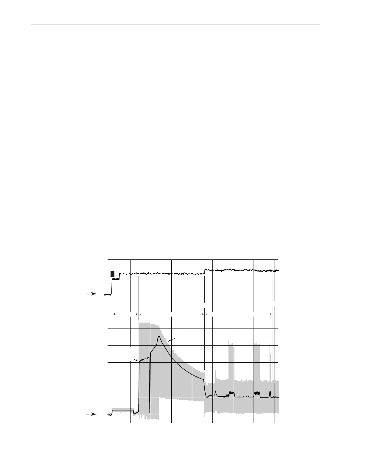
6.2.3 12 V - Current profile
Figure 3 identifies the drive +5 V and +12 V current profile. The current during the various times is as shown:
T - Power is applied to the drive.
T1 - Controller self tests are performed.
T2 - Spindle begi ns to accelerate under current limiting after performing drive internal
diagnostics. See Note 1 of Table 2.
T3 - The heads move from the landing zone to the data area.
T4 - The adaptive servo calibration sequence is performed.
T5 - Ca libration is complete and the drive is ready for reading and writing.
Note. All times and currents are typical. See Table 2 for maximum current requirements.
1.0
+5V
Current
(amps)
5V GND
+12V
Current
(amps)
12V GND
3.0
2.5
2.0
1.5
1.0
0.5
0.0
.5
T
T3
T1 T2 T4
AC
Component
Nominal
(average)
DC curve
T
T5
0.0 2 4 6 8 10 12 14 16
TIME (seconds)
Figure 3. Typical Barracuda 4XL family drive +5 V and +12 V current profile
Page 33

Barr acuda 4X L P roduct Manual, Rev. B 23
6.3 Power dissipation ST34572N/W/WC and ST32272N/W/WC
For drives with single ended interface circuits, typical operating random read power dissipation is 12.9 watts
(44 BTUs per hour) of DC pow er average at nominal v ol tages . Typical power dissipation under idle conditions is
8.8 watts (30 BTUs per hour).
ST34572WD/DC and ST32272WD/DC
For drives with differential interfa ce circuits, typical operating random read powe r dissipation is 14.4 watts (49
BTUs per hour) of DC power average at nominal voltages. Typical power dissipation under idle conditions is 10
watts (34 BTUs per hour).
6.4 Environmental limits
Temperature and humidity values experienced by the drive must be such th at con densat ion doe s not oc cur on
any drive part. Altitude and atmospheric pressu re specifications are referenced to a standard day at 58.7°F
(14.8°C). Maximum Wet Bulb temperature is 82°F (28°C).
6.4.1 Temperature
a. Operating
The drive meets all specifications over a 41°F to 122°F (5°C to 50°C) drive ambient temperature range with
a maximum temperature gradient of 36°F (20°C) per hour. The enclosure for the drive should be designed
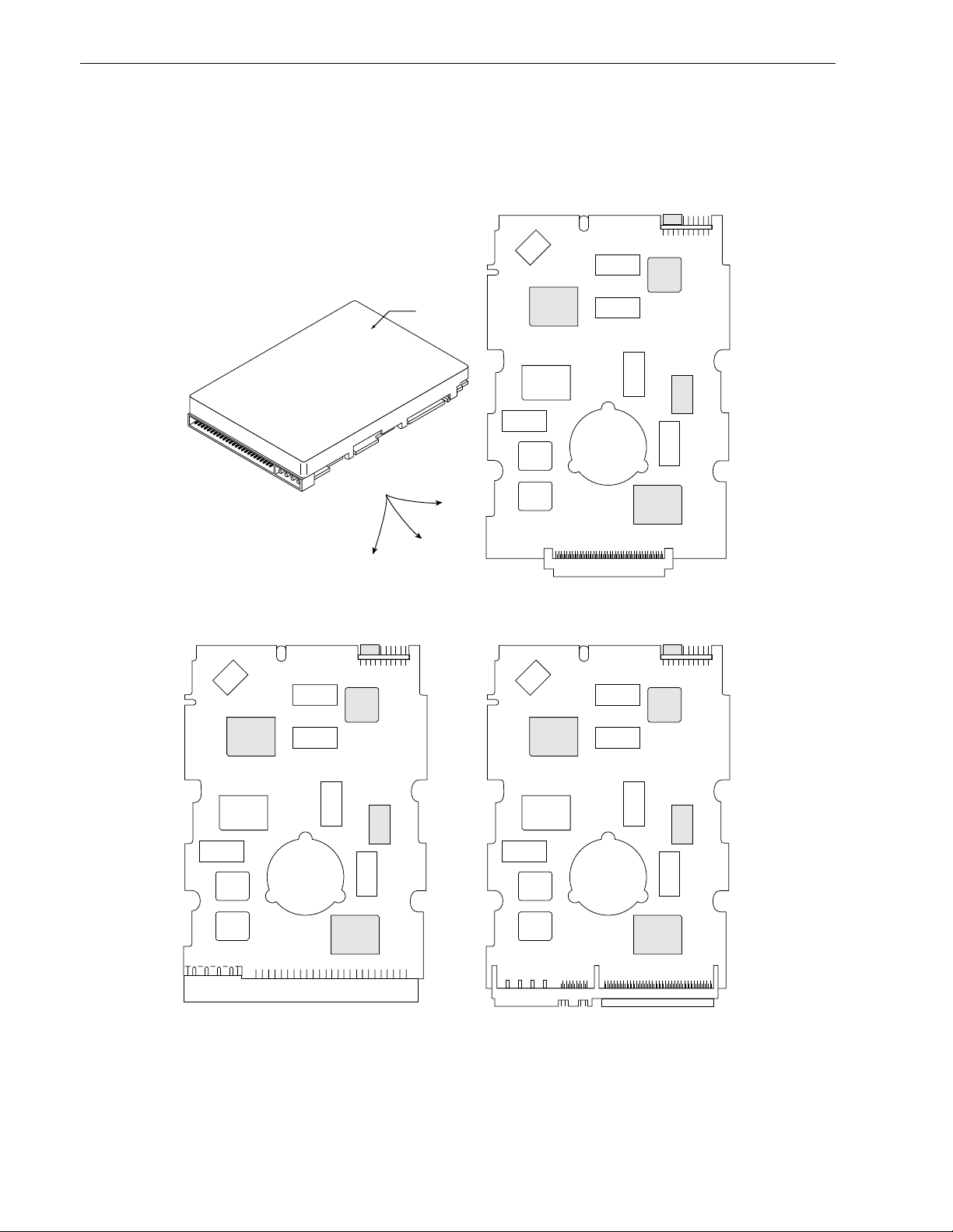
such that the temperatures at the locations specified in Table 3, column 1 are not exceeded. Air flow ma y be
needed to achieve these temperature values. Operation at case tem peratures [3] ab ove these values may
adversely affect the drives ability to meet specifications.
The MTBF specification for the drive is based on operating in an environment that ensures tha t the case
temperatures specified in Table 3, column 2 are not exceeded. Occasional excursions to drive ambient temperatures of 122°F (50°C) or 41°F (5°C) may occur without impact to specified MTBF. Air flow may be
needed to achieve these temperatures. Continual or sustained operation at case temperatures above these
values may degrade MTBF.
To confirm that the required cooling for the Barracuda electronics and HDA is provided, place the drive in its
final mechanical configuration, perform random write/read operations. After the temperatures stabilize,
measure the case temperature of the components listed in Ta ble 3.
Operation of the drive at the maximum case temperature is intended for short time periods only. Continuous
operation at the elevated temperatures will reduce product reliability.
T able 3: PCB and HDA temperatures
Items in
Figure 4
Column 1
maximum case
temperatures
operating (50°C ambient) [1]
Column 2
Maximum allowable
case temperature to
meet MTBF spec.
HDA [2] 140°F (60 °C) 113°F (45°C)
U2 [3] 178°F (81°C) 142°F (61°C)
U4 [3] 183°F (84°C) 147°F (64°C)
U5 [3] 194°F (90°C) 158°F (70°C)
U13 [3] 174°F ( 7 9°C) 138°F (59 °C)
Note.
[1] The temperatures in Column 1 are calculated and m ay not reflect actual operating values. Sufficient
cooling air may be required to ensure that these values are not exceeded.
[2] Measure HDA temp at point labeled “HDA” on Figure 4.
[3] PCB mounted integrated circuit case.
Page 34
24 Barracuda 4XL Product Manual, Rev. B
b. Non-operating
–40° to 158°F (–40° to 70°C) package ambient with a maximum gradient of 45°F (25°C) per hour. This
specification assumes that the drive is packaged in the shipping container designed by Seagate for use with
drive.
Model “N” PCB
HDA
Model “WC/DC” PCB
U17
U13
U14
U16
U19
U15
J1
U8
U6
*
U5
U7
U2
U1
U4
PCB 3
*
Model “W/WD” PCB
*
U16
U17
U19
U15
U14
U13
U8
U6
J1
PCB 1
U7
U4
U5
U1
U2
Bottom side of PCB
*
U16
U17
U19
U15
U14
U13
U8
U6
U7
J1
PCB 2
Figure 4. Locations of printed circuit board (PCB) components listed in Table 3
U5
U2
U1
U4
Page 35

Barr acuda 4X L P roduct Manual, Rev. B 25
6.4.2 Relative humidity
The values below assume that no condensation on the drive occurs.
a. Operating
5% to 90% relative humidity with a maximum gradient of 10% per hour.
b. Non-operating
5% to 95% relative humidity.
6.4.3 Effective altitude (sea level)
a. Operating
–1,000 to +10,000 feet (–305 to +3,048 meters)
b. Non-operating
–1,000 to +40,000 feet (–305 to +12,210 meters)
6.4.4 Shock and vibration
Shock and vibration limits speci fied in this doc um ent are me asured di re ctly o n the drive chassis. If the drive is
installed in an enclosure to which the stated shock and/or vibration criter ia is applied, resonances may occur
internally to the enclosure resulting in drive movement in excess of the stated limits. If this situation is apparent,
it may be necessary to modify the enclosure to minimize drive movement.
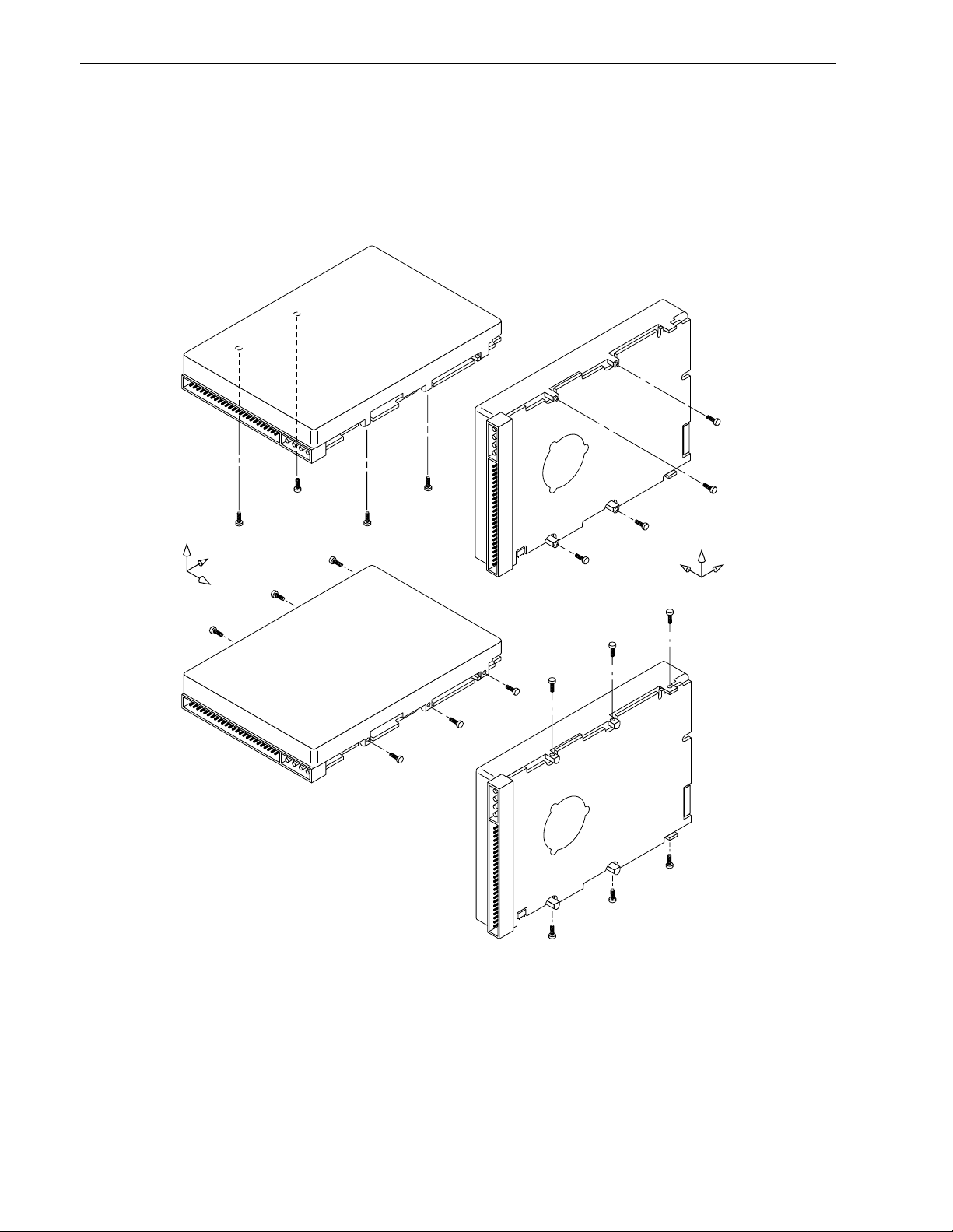
The limits of shock and vibration defined within this document are specified with the drive mounted by any of
the four methods shown in Figure 5, a nd in accordanc e with the re strictions of Section 8.4. Orien tation of the
side nearest the LED may be up or down.
6.4.4.1 Shock
a. Operating—normal
The drive, as installed f or normal operation, shall operate error free while subjected to intermittent shock not
exceeding 2 g at a maximum duration of 11 ms (half sinewave). S hock may be applied in the X, Y, or Z axis.
b. Operating—abnormal
Equipment, as installed for nor mal operation, does not incur physical damage while subjected to interm ittent shock not exceeding 10 g at a maximum duration of 11 ms (half sinewave). Shock occurring at abnormal levels may promote degraded operational performance during the abnormal shock period. Specified
operational performance will continue when normal operating shock levels resume. Shock may be applied
in the X, Y, or Z axis. Shock is not to be repeated more than two times per second.
c. Non-operating
The limits of non-operating shock shall apply to all conditions of handling and transportation. This includes
both isolated drives and integrated drives.
The drive subjected to nonrepetitive shock not exceeding 75 g at a maximum durat ion of 11 ms (half sinewave) shall not exhibit device damage or performance degradation. Shock may be applied in the X, Y, or Z
axis.
The drive subjected to nonrepetitive shock not exceeding 100 g at a maximum duration of 2 msec (half sinewave) does not e x hibit de vice damage or performance degradation. Shock may be applied in the X, Y, or Z
axis.
d. Packaged
Disc drives shipped as loose load (not palletized) general freight will be packaged to withstand dro ps from
heights as defined in the table below. For additional details refer to Seagate specifications 30190-001
(under 100 lbs/45 kg) or 30191-001 (over 100 lbs/45 Kg).
Package size Packaged/product weight Drop height
<600 cu in (<9,800 cu cm) Any 60 in (1524 mm)
Page 36
26 Barracuda 4XL Product Manual, Rev. B
Package size Packaged/product weight Drop height
600-1800 cu in (9,800-19,700 cu cm) 0-20 lb (0 to 9.1 kg) 48 in (1219 mm)
>1800 cu in (>19,700 cu cm) 0-20 lb (0 to 9.1 kg) 42 in (1067 mm)
>600 cu in (>9,800 cu cm) 20-40 lb (9.1 to 18.1 kg) 36 in (914 mm)
Z
Y
X
Note. Use four screws (two per side) when
using the mounting holes located on
the sides of the drive.
See Section 8.4 when using the
mounting holes located on the
bottom of the drive.
Figure 5. Recommended mounting
X
Z
Y
Page 37

Barr acuda 4X L P roduct Manual, Rev. B 27
6.4.4.2 Vibration
a. Operating - normal
The drive as installed for normal operation, shall comply with the complete specified performance while
subjected to continuous vibration not exceeding
5-350 Hz @ 0.5 g
Vibration may be applied in the X, Y, or Z axis.
b. Operating - abnormal
5-350 Hz @ 0.75 g (X, Y, or Z axis)
c. Non-operating
The limits of non-operating vibration shall apply to all conditions of handling and transportation. This
includes both isolated drives and integrated drives.
The drive shall not incur physical damage or degraded performance as a result of continuous vibration not
exceedi ng
5-22 Hz @ 0.081 inches (2.05 mm) displacement
22-350 Hz @ 2.00 g
Vibration may be applied in the X, Y, or Z axis.
6.4.5 Air cleanliness
The drive is designed to operate in a typical office environment with minimal environmental control.
6.4.6 Acoustics
Sound power during idle mode shall be 4.2 bels typical when measured to Seagate’s 30553-001 specification.
6.4.7 Electromagnetic susceptibility
See Section 2.1.2.
Page 38
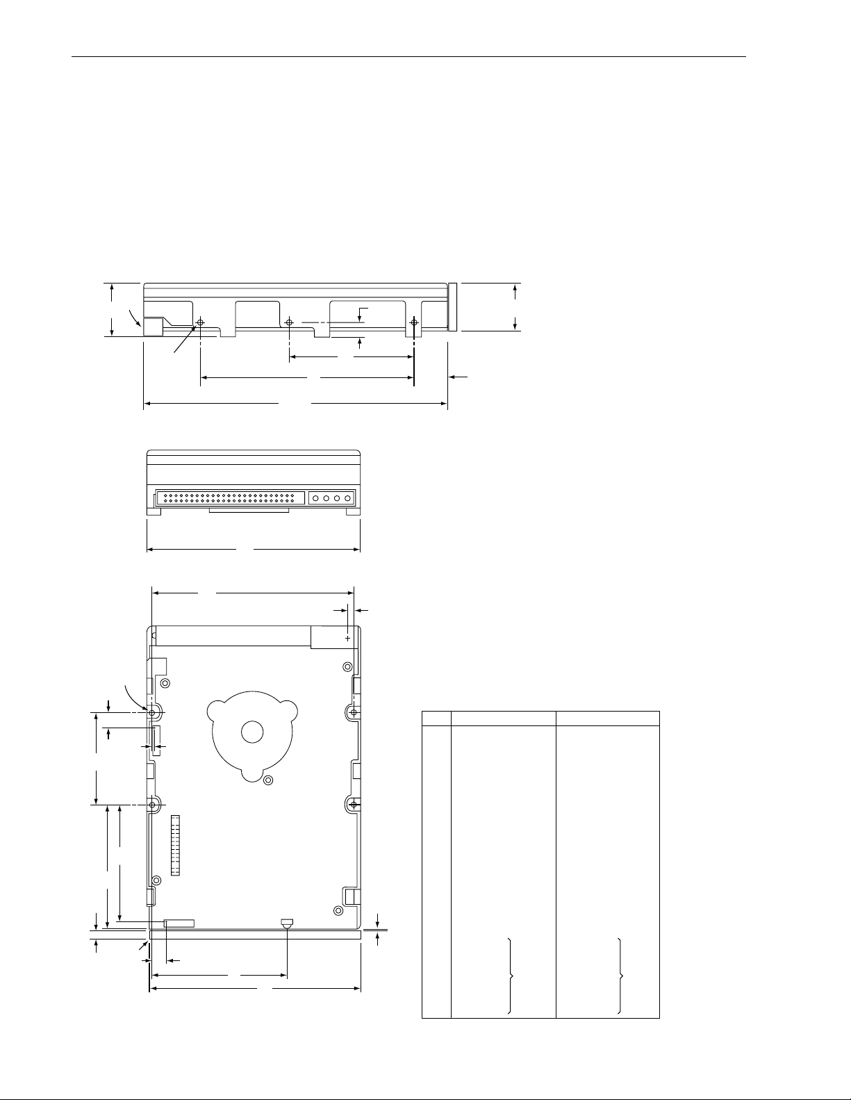
28 Barracuda 4XL Product Manual, Rev. B
6.5 Mechanical specifications
The following nominal dimensions are exclusive of the decorative front panel accessory. However, dimensions
of the front panel a re shown in figure below. Refer to Figures 6, 7, and 8 for detailed mounting c onfiguration
dimensions. See Section 8.4, “Drive mounting.”
Height: 1.00 in 25.4 mm
Width: 4.00 in 101.6 mm
Depth: 5.74 in 145.8 mm
Weight: 1.5 pounds 0.68 kilograms
[4]
H
N
C
S [7]
[7] T
W [6]
K
[3]
[2]
[4]
[1]
B
J
J2
J6 LED
U [6]
V
G
L
D
F
E
A [3]
Notes:
[1]
Mounting holes three on each side, 6-32 UNC. Max
screw length into side of drive 0.15 in. (3.81 mm). Screw tightening
torque 6.0 in-lb (.675 NM) max with minimum thread engagement of
0.12 in. (3.05 mm).
[2]
Mounting holes four on bottom, 6-32 UNC. Max screw length into
bottom of drive 0.15 in. (3.81 mm). Screw tightening torque 6.0 in-lb
(.675 NM) max with minimum thread engagement of 0.12 in. (3.05 mm).
[3]
Power and interface connectors can extend past the “A” dimension
by 0.040 in. (1.02 mm).
[4]
Decorative front panel (optional).
[5]
Centerline of pad for Pin 1 of power connector.
[5] R
M
[6]
Centerline of pad for Pin 1 of J6. Pin ends on J6 are nominally
flush with end of drive.
[7]
Centerline of pad for Pin 1 of J2. Dimensions indicated are for
reference only.
[8]
Dimensions to Pin 1 of each connector are nominal values.
Dimension Table
Inches
A
5.74
4.00
1.00
2.362
.620
4.000
.250
1.750
3.750
2.370
1.00
4.000
0.19
0.015
0.143
0.260
0.030
0.386
2.265
2.075
± .010
± .010
+ .021
– .009
± .010
± .020
± .010
+ .010
– .005
± .010
± .010
± .020
± .010
± .010
± .010
max
[8]
B
C
D
E
F
G
H
J
K
P
L
M
N
P
R
S
T
U
V
W
Millimeters
145.80
101.60
25.40
60.00
15.75
101.60
6.35
44.45
95.25
60.20
25.4
101.6
4.83
0.381
3.63
6.60
0.76
9.80
57.53
52.71
± .25
± .25
+ .53
– .22
± .25
± .50
± .25
+ .25
– .12
± .25
± .25
± .50
± .25
± .25
± .25
max
[8]
Figure 6. Mounting configuration dimensions for models “N”
Page 39
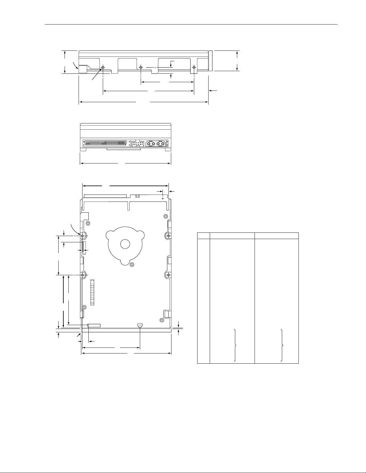
Barr acuda 4X L P roduct Manual, Rev. B 29
[4]
H
N
C
S [7]
[7] T
W [6]
K
[2]
[3]
[4]
[1]
B
J
J2
J6 LED
U [6]
V
G
L
D
F
E
A [3]
Notes:
[1]
Mounting holes three on each side, 6-32 UNC. Max
screw length into side of drive 0.15 in. (3.81 mm). Screw tightening
torque 6.0 in-lb (.675 NM) max with minimum thread engagement of
0.12 in. (3.05 mm).
[2]
Mounting holes four on bottom, 6-32 UNC. Max screw length into
bottom of drive 0.15 in. (3.81 mm). Screw tightening torque 6.0 in-lb
(.675 NM) max with minimum thread engagement of 0.12 in. (3.05 mm).
[3]
Power and interface connectors can extend past the “A” dimension
by 0.040 in. (1.02 mm).
[4]
Decorative front panel (optional).
[5]
Centerline of pad for Pin 1 of power connector.
[5] R
M
[6]
Centerline of pad for Pin 1 of J6. Pin ends on J6 are nominally
flush with end of drive.
[7]
Centerline of pad for Pin 1 of J2. Dimensions indicated are for
reference only.
[8]
Dimensions to Pin 1 of each connector are nominal values.
Dimension Table
Inches
A
5.74
4.00
1.00
2.362
.620
4.000
.250
1.750
3.750
2.370
1.00
4.000
0.19
0.015
0.143
0.260
0.030
0.386
2.265
2.075
± .010
± .010
+ .021
– .009
± .010
± .020
± .010
+ .010
– .005
± .010
± .010
± .020
± .010
± .010
± .010
max
[8]
B
C
D
E
F
G
H
J
K
L
P
M
N
P
R
S
T
U
V
W
Millimeters
145.80
101.60
25.40
60.00
15.75
101.60
6.35
44.45
95.25
60.20
25.4
101.6
4.83
0.381
3.63
6.60
0.76
9.80
57.53
52.71
± .25
± .25
+ .53
– .22
± .25
± .50
± .25
+ .25
– .12
± .25
± .25
± .50
± .25
± .25
± .25
max
[8]
Figure 7. Mounting configuration dimensions for models “W” and “WD”
Page 40
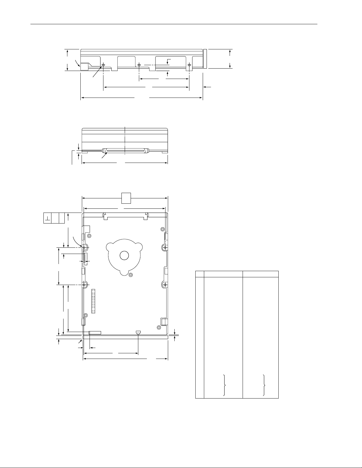
30 Barracuda 4XL Product Manual, Rev. B
[4]
[8]
[3]
C
[1]
R
Pin 1
Connector Centerline
XT
S [6]
[2]
Z [10]
[10] Y
J2
H
W [9]
K
N
[4]
A [3]
[5]
B
[8]
X
J
J6 LED
U [9]
V
G
L
D
F
Notes:
[1]
[2]
[3]
[4]
[5]
[6]
[7]
[8]
[9]
[10]
[11]
P
M
E
Mounting holes three on each side, 6-32 UNC. Max screw length
into side of drive 0.15 in. (3.81 mm). Screw tightening torque 6.0
in-lb (.675 NM) max with minimum thread engagement of 0.12 in.
(3.05 mm).
Mounting holes four on bottom, 6-32 UNC. Max screw length into
bottom of drive 0.15 in. (3.81 mm). Screw tightening torque 6.0 inlb (.675 NM) max with minimum thread engagement of 0.12 in.
(3.05 mm).
Interface connector is flush with the end of drive within
±0.020 in. (.5 mm). The interface connector location may extend
beyond HDA dimension "A" by 0.020 in. (.5 mm).
Decorative front panel (optional).
Connector J1 is centered (side to side) on drive within ±0.020 in.
(.508 mm).
Dimension "S" is from bottom rear drive mounting holes center(s)
to the face of the connector at the center of the drive.
Dimensions "S" and "T" are unique requirements for SCA drives
only, required for conformance with latest ANSI SFF Spec #8337.
Maximum connector non-perpendicularity to side planes pointed
to by X.
Centerline of pad for Pin 1 of J6. Pin ends on J6 are nominally
flush with end of drive.
Centerline of pad for Pin 1 of J2. Dimensions indicated are for
reference only.
Dimensions to Pin 1 of each connector are nominal values.
Dimension Table
[7]
[8]
Inches
5.74
4.00
1.00
2.362
.620
4.000
.250
1.750
3.750
2.370
1.00
4.000
0.19
0.015
0.181
1.62
.015
0.386
2.265
2.075
0.030
0.260
± .010
± .010
+ .021
– .009
± .010
± .020
± .010
+ .010
– .005
± .010
± .010
± .020
± .010
± .010
± .010
max
+ .015
– .010
± .02
[11]
A
B
C
D
E
F
G
H
J
K
L
M
N
P
R
S
T
U
V
W
Y
Z
Millimeters
145.80
101.60
25.40
60.00
15.75
101.60
6.35
44.45
95.25
60.20
25.4
101.6
4.83
0.381
4.597
41.15
.38
9.80
57.53
52.71
0.76
0.60
± .25
± .25
+ .53
– .22
± .25
± .50
± .25
+ .25
– .12
± .25
± .25
± .50
± .25
± .25
± .25
max
+ .38
– .25
± .50
[11]
Figure 8. Mounting configuration dimensions for models “WC” and “DC”
Page 41

Barr acuda 4X L P roduct Manual, Rev. B 31
7.0 Defect and error management
The drive, as delivered, complies with this specification. The read error rate and specified storage capacity are
not dependent upon use of defect management routines by the host (initiator).
Defect and error management in the SCSI system involves the drive internal defect/error managem ent and
SCSI systems error considerations (errors in communications between Initiator and the dri ve). Tools for use in
designing a defect/error management plan are briefly o utlined in this section, with references to other sections
where further details are given.
7.1 Drive internal defects and errors
Identified defects are recorded on the drive defects list tracks (referred to as the primar y or ETF defect list).
These known defects are reallocated during the initial drive format operation at the factory. (See Section
5.2.1.2, “Format Unit command” in the
tion by ECC will be applied to recover data from additional flaws if they occur.
SCSI Interface Product Manual
, part number 77738479). Data correc-
Details of the SCSI commands supported by the drive are described in
7.2 SCSI systems errors
Information on the reporting of operational errors or faults across the interface is given in the SCSI I nterface
Product Manual. Message Protocol System is described in the
messages are used in the SCSI systems error manage ment system. The Request Sense command retur ns
information to the host abou t numerous kinds of errors or faults. The Receive Diagnostic Resul ts reports th e
results of diagnostic operations performed by the drive.
Status returned by the drive to the Initiator is described in the
plays a role in the SCSI systems error management and its use in that respect is described in sections where
the various commands are discussed.
SCSI Interface Product Manual
SCSI Interface Product Manual
SCSI Interface Product Manual
. Several of th e
. Status reporting
.
Page 42

Page 43

Barr acuda 4X L P roduct Manual, Rev. B 33
8.0 Installati on
The first thing to do wh en installing a dri ve is to set the drive ID (sele ct) on the SCSI bus and set up cer tain
operating options. This is usually done by installing small shorting jumpers on the pins of connector J2 on the
PCB (or J1-Auxiliary on the “W” models), or via the drive to host I/O signals on “WC” models. Some users connect cables to J6 or J1-Auxiliary and perform the set-up using remote switches.
If your syste m is “SCAM” (SCSI Configur ed Aut o Magically ) complian t, the syst em assigns the driv e ID ov er the
interface, so there is no need to be con cerned ab out drive ID. Setting the drive ID jumpers doe sn’t hur t anything, but is not necessary.
If your system is not “SCAM” compliant you need to set the drive ID using the ID jumpers.
Configure drive optio ns
For option jumper locations and definitions refer to Figures 9, 10, 11, 12, and 13. Drive default mode parameters are not normally need ed for installation. Refer to Section 9.3.2 for default mode parameters if they are
needed.
• Ensure that the SCSI ID of the drive is not the same as the host adapter. Most host adapters use SCSI ID 7.
ID 7 is the highest priority on both 8 and 16 bit data buses.
• If multiple devices are on the bus set the drive SCSI ID to one that is not presently used by other devices on
the bus.
• If the drive is the only device on the bus, attach it to the end of the SCSI bus cable. Permanently installed terminators must be enabled on the drive for “N” and “W” models using jumper plug TE if termination is not provided by the host equipment. On “WC”, “WD,” and “DC” models, external terminators must be provided by
the user, systems integrator or host equipment manufacturer.
• If the drive is attached to a bus that contains ot her devices, and the new drive is not attached to the end of
the bus, the Terminator Enable jumper (TE) should be removed from the new drive.
Note. For additional information about term inator requirem ent s, refer to Sections 9.8 and 9.9.
• Set all appropriate option jumpers for desired operation prior to power on. If jumpers are changed after
power has been applied, recycle the drive power to make the new settings effective.
• Installation instructions are provided by host system document ation or with any additiona lly purchased drive
installation software. If necessary see Section 10 for Seagate support ser vice s telephone numbers.
• Do not remove the manufacturer’s in stalled labels from the dri ve and do not cover with additional labels, as
the manufacturer labels contain information required when ser vicing the product.
Formatting
• It is not necessary to low level format this drive. The drive is shipped from the factory low level formatted in
512 byte sectors.
• Reformat the drive if a different spare sector allocation scheme is selected.
• High level format the dr ive involves assigning one or more partitions or logical dr ives to the drive volume.
Follow the instructions in the system manuals for the system into which the drive is to be installed.
• Systems that have Windows 95 Operating System version 950B (thi s has FAT 32) or later do not need t o
partition the drive.
8.1 Drive ID/option select header
Figures 9 through 11 show views of th e drive ID select jumper connecto rs. Figure 12 shows the op tion select
jumper connector for all models. Figure 10 shows a rear view of model drives for the purpose of showing J1auxiliary of the drive. Both J1-auxil iary and J6 have pins for selecting drive ID and for connecting the remote
LED cable. Only one or the other should be used, although using both at the same time would not damage the
drive. The notes following the figures desc ri be t he functions of the various jumper positions on the c onne ctors
J2, J1-Auxiliary and J6. Suggested part number for the jumpers used on J2 is Molex 52747-0211(Seagate P/N
77679052). Suggested part number for the jumpers used on J1-Auxiliary and J6 are Method Electronics 861M-
202-70 (Seagate part number 15481851). A bag with the two jumper plug types is shipped with standard OEM
drives.
Page 44
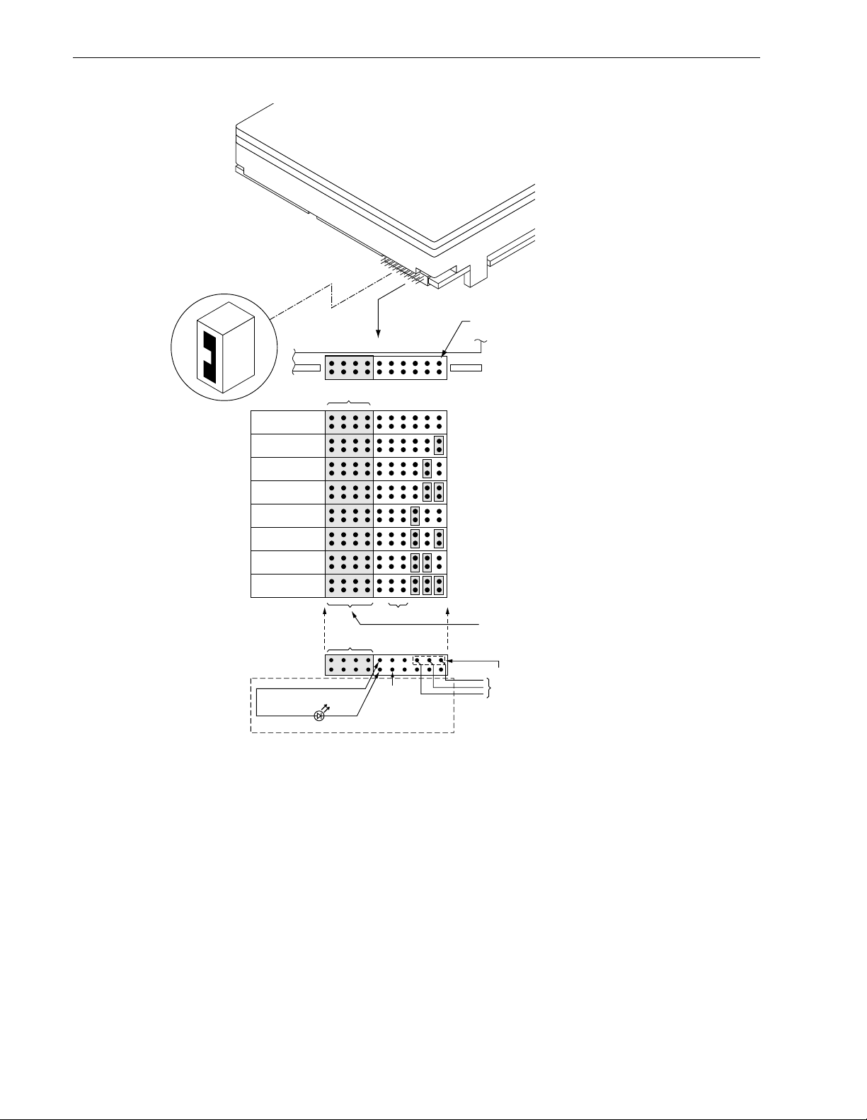
34 Barracuda 4XL Product Manual, Rev. B
Drive
Front
Jumper Plug
(enlarged to
show detail)
Pin 1
J6
L
R
Reserved
SCSI ID = 0 (default)
SCSI ID = 1
SCSI ID = 2
SCSI ID = 3
SCSI ID = 4
SCSI ID = 5
SCSI ID = 6
SCSI ID = 7
R
E
E
E
A2A1A
D
S
0
S
Shipped with cover installed.
Do not install jumpers;
retain cover.
Optional connections
to switching circuits in
host equipment to
Host
[4]
Alternate
Usage Plug:
+5V
Reserved
Pins
[3]
1197531
642
Ground
establish drive ID. [4]
Drive Activity LED
Dashed area is optional host circuitry (external to the drive)
[4]
connected to host supplied optional usage plug.
Do not connect anything to pins 13-20.
Figure 9. Barracuda 4XL famil y drive ID select header for models “N”
Notes for Figures 9 through 13 are in Section 8.1.1.
Page 45
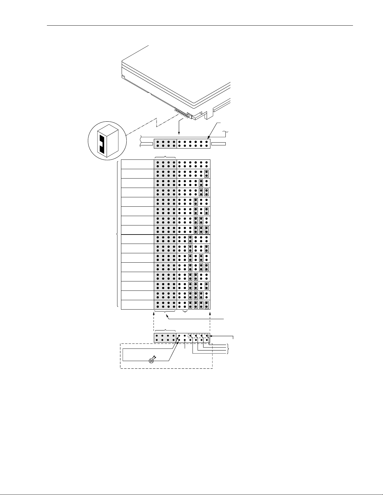
Barr acuda 4X L P roduct Manual, Rev. B 35
Drive
Front
Jumper Plug
(enlarged to
show detail)
Pin 1
[1]
J6
R
Pins
1197531
[8]
L
E
E
S
D
[3]
Ground
A2A1A
A
3
6842
0
Shipped with cover installed.
Do not install jumpers;
retain cover.
Optional connections
to switching circuits in
host equipment to
establish drive ID. [4]
Reserved
SCSI ID = 0 (default)
SCSI ID = 1
SCSI ID = 2
SCSI ID = 3
SCSI ID = 4
SCSI ID = 5
SCSI ID = 6
SCSI ID = 7
[4]
SCSI ID = 8
SCSI ID = 9
SCSI ID = 10
SCSI ID = 11
SCSI ID = 12
SCSI ID = 13
SCSI ID = 14
SCSI ID = 15
[4]
Host
Reserved
Alternate
Usage Plug:
+5V
Drive Activity LED
Dashed area is optional host circuitry (external to the drive)
[4]
connected to host supplied optional usage plug.
Do not connect anything to pins 13-20.
Figure 10. Barracuda 4XL fami ly drive ID select for models “W,” “WC,” “WD ,” and “DC”
Page 46
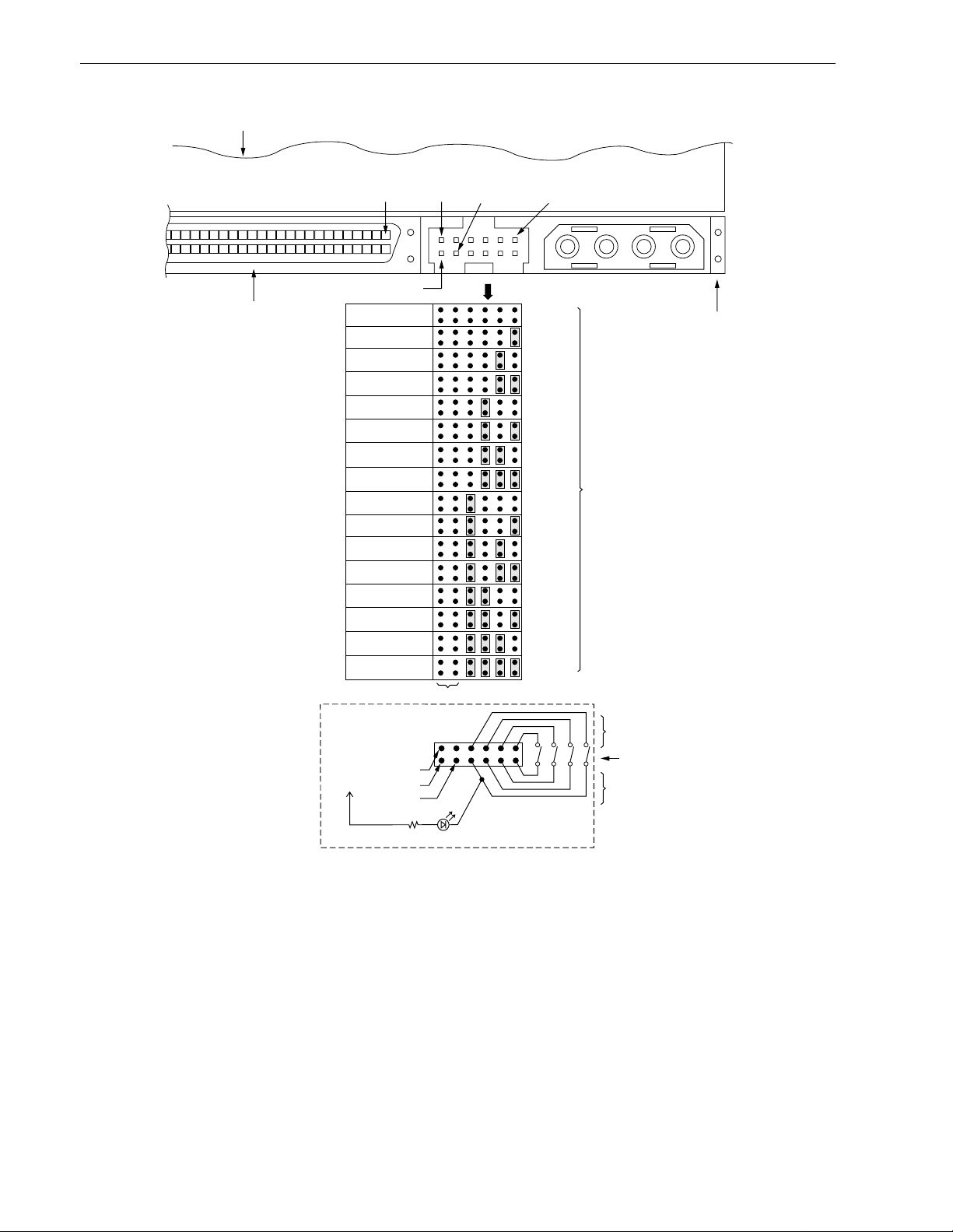
36 Barracuda 4XL Product Manual, Rev. B
Drive HDA (rear view, PCB facing downward)
68 Pin
SCSI I/O Connector
J1
[4]
Pin 1
Pin 12A
+5V Ground
Pin 1A
[2]
SCSI ID = 0 (default)
SCSI ID = 1
SCSI ID = 2
SCSI ID = 3
SCSI ID = 4
SCSI ID = 5
SCSI ID = 6
SCSI ID = 7
SCSI ID = 8
SCSI ID = 9
SCSI ID = 10
SCSI ID = 11
SCSI ID = 12
SCSI ID = 13
SCSI ID = 14
SCSI ID = 15
J1-Auxiliary
[3]
A3A2A
A
1
0
Host Alternate
Usage Plug
+5V
Dashed area is optional host circuitry (external to the
drive) connected to host supplied optional usage plug.
[4]
1197531
[6]
12 10 8 6 4 2
+5V
N.C.
Ground
220 ohm
Drive Activity LED
[7]
A0A1A2A
3
[1] [2]
1P2P3P4P
J1-DC Power
For ID selection use
jumpers as shown or
connect a cable for
remote switching as
shown below.
Pins 1, 3, 5, and 7 are
optional connections to
switching circuits in host
equipment to establish
drive ID. [4]
Remote Switches
Pins 2, 4, 6, and 8 are
normally not grounded.
They are driven low (ground)
for 250 ms after a Reset
or PWR ON to allow drive to
read SCSI ID selected. [4]
PCB
Figure 11. Barracuda 4XL fami ly drive ID select header J1-auxiliary for mode ls “W ” and “W D”
(J1-Auxiliary Pins 1A - 12A)
Page 47
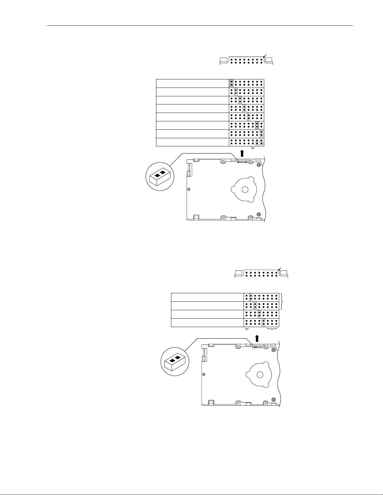
Barr acuda 4X L P roduct Manual, Rev. B 37
Caution:
Do not use J2 jumper
plugs on J6 or J1Auxiliary, as the internal
contacts will be deformed
and can not be used on
J2 without them falling off.
Jumper
Positions
Terminator Enable
Delay Motor Start
Enable Motor Start
Write Protect
J2
TEDSMEWPP
D
Pin 1
R
T
T
E
P
P
S
2
1
(default - models
“N” and “W” only)
Parity Disable
(default - models
“N” and “W” only)
(Position A)
[3]
*Additional notes on these
functions in section 8.1.2.
J2
*
Jumper Plug
Term. Power from Drive
Term. Power to SCSI Bus
Term. Power from SCSI Bus
J2
J6
(enlarged to
show detail)
Drive
Front
Figure 12. Barracuda 4XL fami ly drive option select header for models “N,” “W,” and “WD”
Caution:
Do not use J2 jumper
plugs on J6, as the
internal contacts will be
deformed and can not be
used on J2 without them
falling off.
Jumper
Positions
Delay Motor Start
Enable Motor Start
R
ESDSMEWPP
J2
D
Pin 1
R
R
R
E
E
E
S
S
S
[5]
Write Protect
*Additional notes on these
functions in section 8.1.2.
J2*
Jumper Plug
Parity Disable
[3] [3]
J2
J6
(enlarged to
show detail)
Drive
Front
Figure 13. Barracuda 4XL family drive option select header for models “WC” and “DC”
Page 48
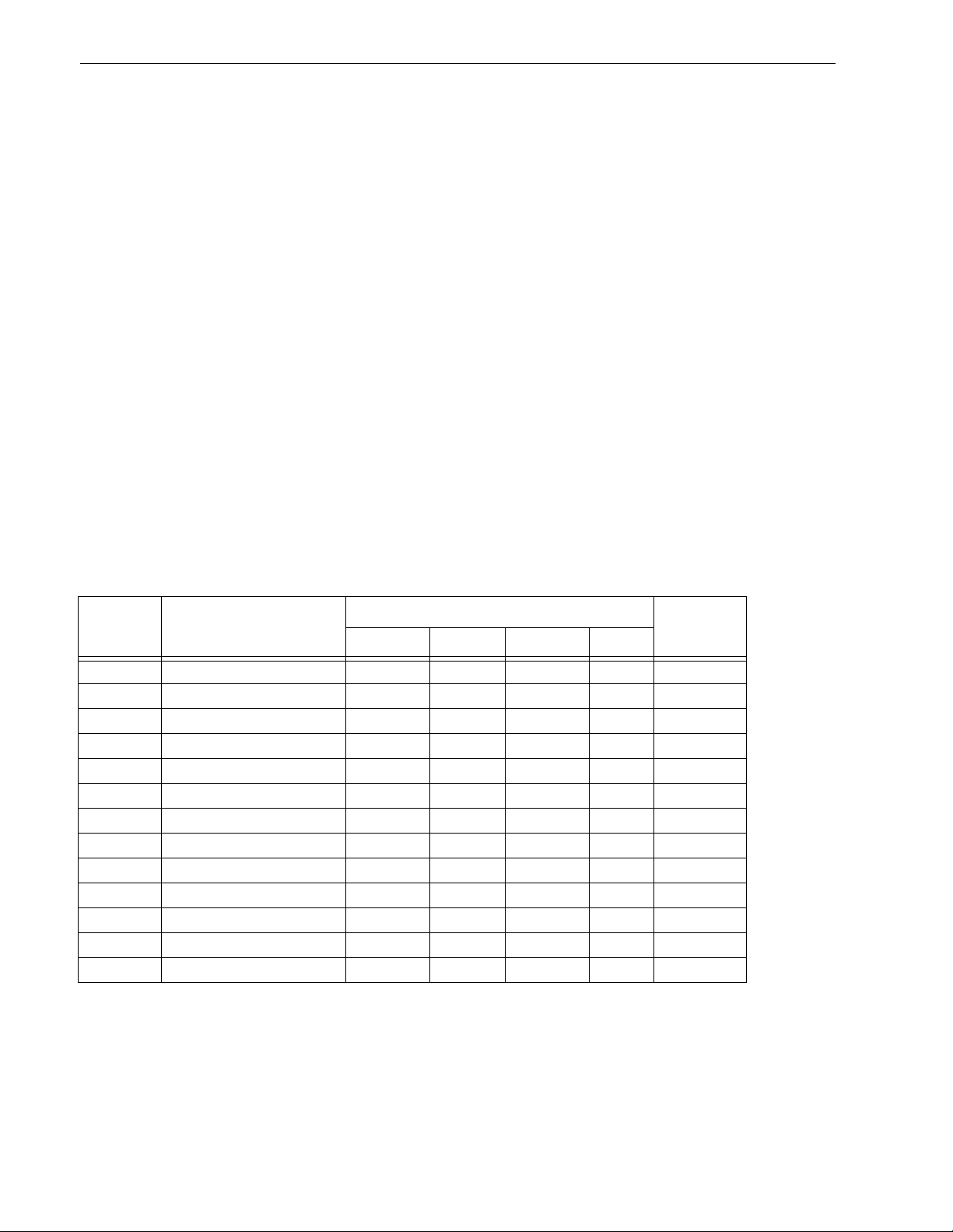
38 Barracuda 4XL Product Manual, Rev. B
8.1.1 Notes for Figures 9, 10, 11, 12, and 13.
[1] Notes explaining the functions of the various jum pers on jumper heade r connectors J2, J1-Auxiliar y and
J6 are given here a nd in Section 8. 1.2. Th e t erm “default” means as standard OEM units are configured
with a jumper on those pos itions when shipped from factory. “Off” means no jumper is installed; “On”
means a jumper is installed. OFF or ON underlined is factory defau lt c ondition .
[2] The PCB on “N,” “WC,” and “DC” model drives does not have connector J1-Auxiliary. The J1-Auxiliary
connector signals conform to SFF-8009 Revision 2.0, Unitized Connector for Cabled Drives, signal
assignments for auxiliary connectors. See note [4].
[3] Reserved useage. Do not install any jumpers.
[4] Table 4 summarizes the configuration selection possibilities available on the different Barracuda 4XL
model drives.
[5] These signals are also on 80 pin J1. See Tables 16 and 17.
[6] Voltage supplied by the drive.
[7] J1A Drive Activity LED—with ser ies resistor built-in pin 12, is the open collector driver that drives the
external LED minus side low to turn it on. This output is capable of driving > 20mA. This is the same signal
as on J6 pin 12, except J1A pi n 8 goes t hrough a 220 Ohm resistor. Tie the minus side of the external LED
to this pin.
[8] J6 Drive Activity LED—without series resistor built-in pin 8, is the open collector driver that drives the
external LED minus side low to turn it on. This output is capable of driving > 20mA. This is the same signal
as on J1A pin 8, except J6 pin 12 does not go through a 220 Ohm resistor. Tie the minus side of the exter-
nal LED to this pin.
T able 4: Drive configuration selections summary
Connector
Interface
type Function
Applicable
figureJ1 J6 J1-AUX J2
N Drive ID X, Y none 9
N Drive Activity LED Y [c] none 9
N Option select none X 12
W, WD Dri ve I D X, Y X, Y [e] 10, 1 1 [a ]
W, WD Drive Activity LED Y [c] Y [c] 10, 11 [a]
W, WD Option select X 12
WC, DC Drive ID Y[f] X, Y none 10 [d]
WC, DC Drive Activity LED Y [b][c] Y [c] none 10 [d]
WC, DC Option select:
Delayed Mtr Start Y[b] none X 13
Enable Mtr Start Y[ b] none X 13
Write Protect none X 13
Parity Disable none X 13
(“X” means the function selection can be made with jumpers on that connector;
(“Y” means the signal is available to host through that connector.)
Notes for Table 4 [ ]:
[a] Use either J6 or J1-Aux, but not both.
[b] I/O connector J1 plugs directly into host. No jum per can be installed on J1. The host supplies the logic
state of these function signals causing the selection of these functions. See pinout Table 16.
Page 49

Barr acuda 4X L P roduct Manual, Rev. B 39
[c] The host can dr ive a remotely located Drive Activity LED using signal.
[d] Use either J1 or J6, but not both.
[e] The drive reads the ID (asserted low) from J1-Auxiliary pins 1, 3, 5 and 7 for 250 ms after power-on or
drive reset. Jumper plugs can be used on J1-Auxiliary pins 1-2, 3-4, 5-6 and 7-8 to set dri ve ID if desired,
but usually a connector/cable is plugged to J1-Auxiliary to run these signals to the host for remote ID
selection.
[f] The host selects drive ID through J1.
Page 50

40 Barracuda 4XL Product Manual, Rev. B
8.1.2 Function description
J2
Jumper
Installation Jumper Function Description
TE (Applies only to “N” and “W” models)
On
With the jumper installed, the On-board (non-removable) terminator circuits are enabled
(connected to the I/O lines). Default is jumper installed.
Off Terminator circuits not enabled (not connected to I/O lines).
DS M E (App lies to all models)
Off
Off Spindle starts immediately after power up - Default setting.
Off On Drive spindle does not start until Start Unit command received from host.
On Off Spindle Star tup is delayed by SCSI ID times 12 seconds after power is applied, i.e., drive 0
spindle starts immediately when DC power connected, drive 1 starts after 12 second delay,
drive 2 starts after 24 second delay, etc.
On On Drive spindle starts when Start Unit command received from host. Delayed start feature is
overridden and does not apply when ME jumper is installed.
WP (Applies to all models)
On Entire drive is write protected.
Off
Drive is not write protected. Default is no WP jumper installed.
PD (App lies to all models)
On Parity checking and parity error reporting by the drive is disabled.
Off
Drive checks for parity and reports result of parity checking to host.
Default is PD jumper not installed.
RES (Applies to all models)
Off
Reserved jumper position. Default is no jumper installed.
TP2 TP1 (Does not app ly to “WC ” or “ DC ” mo del s )
Off Off No terminator power is connected to drive terminators or SCSI bus I/O cable*.
On
Off Drive supplies its own terminator power only. Jumper on this position is factory default.
Off On Drive supplies power to SCSI bus I/O cable*; none to internal terminators. When drives have
differential I/O circuits, a jumper on the TP1 position may be needed to power external terminators (see system documentation). The “WD” drives have differential I/O circuits which have
no terminator circuits on the drive.
On On Drive supplies terminator power to itself (internal connection) and to SCSI bus I/O cable*.
This is a legal jumper setting.
TP1 and TP 2
“Positio n A” (Applies only to “N” and “W”)
On This horizontally positioned jumper across the two TP positions furthest from the PCB edge,
connects terminator power from SCSI bus I/O Termpower cable* to the drive’s internal terminators (for single-ended I/O only).
Off See above explanations for TP jumpers.
*See Figure 12 for pins used for Term power.
Page 51
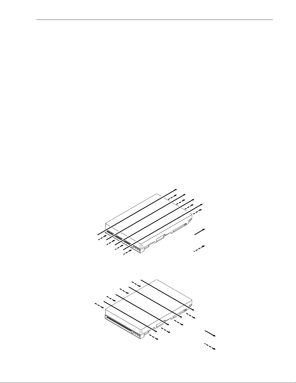
Barr acuda 4X L P roduct Manual, Rev. B 41
8.2 Drive orientation
The balanced rotary arm actuator design of the drive allows it to be mounted in any orientation. All drive performance characterization, however, has been done with the drive in horizontal (discs level) and vertical (drive on
its side) orientations, and these are the two preferred mounting orientations.
8.3 Cooling
Cabinet cooling must be designed by the customer so that the ambient temp erature immedi ately surrounding
the drive will not exceed temper ature conditions specified in Section 6 .4.1, “Temperature.” Specific consideration should be given to make sure adequate air circulation is present around the printed circuit board (PCB) to
meet the requirements of Section 6.4.1, “Temperature.”
8.3.1 Air flow
The rack, cabinet, or dra wer environment for the Barracuda 4XL drive must provide heat remo v al from the electronics and head and disc assem bly (HDA). You should confir m that adequ ate heat removal is provided using
the temperature measurement guidelines descr ibed in Section 6.4.1.
Forced air flow may be required to keep temperatures at or below the specified case temperatures of Table 3,
Column 2, in which case the drive should be or iented, or a ir flow directed, so that the least amount of ai r flow
resistance is created while providing air flow to the electronics and HDA. Also, the shortest possible path
between the air inlet and exit should be chosen to minimize the travel length of air heated by the drive and
other heat sources within the rack, cabinet, or drawer environment.
If forced air is determined to be neces sary, po ssible air-flow patterns are shown i n Fi gure 14. T he ai r-flow patterns are created by one or more fans, either forcing or drawing air as shown in the illustrations. Conduction,
convection, or other forced air-flow patterns are acceptable as long as the temperature measurement guidelines of Section 6.4.1 are met.
Above unit
Under unit
Note. Air flows in the direction shown (front to back)
or in reverse direction (back to front)
Note. Air flows in the direction shown or
in reverse direction (side to side)
Figure 14. Air flow (suggested)
Above unit
Under unit
Page 52

42 Barracuda 4XL Product Manual, Rev. B
8.4 Drive mounting
Refer to Figure 5 on page 26 for an illustration of the recommended mounting orientations
When mounting the dri ve using the bot to m holes (x-y plane in Figure 5) care mu st b e t aken to e nsure t hat the
drive is not physically distorted due to a stiff non-flat mounting surface. The allowable mounting surface stiffness is 80 lb/in (14.0 N/mm). The following equation and paragraph define the allowable mounting surface stiffness:
F
K
--- 80lb/in (14.0 N/mm)==
x
where ‘k’ represents the mounting surface stiffness (units of lb/in or N/mm), and ‘x’ represents the out-of-plane
mounting surface distortion (units of inches or millimeters). The o ut-of-plane distortion (‘x’) is determined by
defining a plane with t hree of the four mounting points fixed and evaluating the out-of-plan e deflection of the
fourth mounting point when a known force is applied to the fourth point.
Note. Before mounting the drive in any kind of 3.5-inch to 5.25-inch adapter frame, verify with Seagate Tech-
nology that the drive can meet t he shock and vibration specifications given herein while mounted in
such an adapter frame. Adapter frames that are available may not have a mechanical structure capable of mounting the drive so t hat it can meet t he shoc k and vibration specifications listed in this manual.
8.5 Grounding
Signal ground (PCB) and HDA ground are connected together in the drive and cannot be separated by the
user. The equipment in which the drive is mounted is connected directly to the HDA and PCB with no electrically isolating shock mounts. If it is desired for the system chassis to not be connected to the HDA/PCB ground,
the systems integrator or user must p rovide a nonconductive (electrically isolating) method of moun ting the
drive in the host equipment.
Increased radiated emissions m ay result if you do not provide the maxi mum surface area ground connection
between system ground and drive ground. This is the system designer’s and integrator’s responsibility.
Page 53

Barr acuda 4X L P roduct Manual, Rev. B 43
9.0 Interface requirements
This section describes Barracuda 4XL interface requirements.
9.1 General description
This section partially describes the interface requirements as im plement ed on t he drives . T he major portion
of the interface requ irements / implementation is descr ibed in the
ber 77738479). This section has tables that give the Barracuda 4XL family drive's version of the SCSI implementation described in the
9.2 SCSI interface messages suppor ted
Table 5 lists the messages support ed by the SCSI-2 and SCSI-3 modes of the Barracuda 4XL family drives.
T able 5: SCSI messages supported by Barracuda 4XL famil y drives
Message name Message code
Abort 06h Y
Abort-tag 0Dh Y
Bus device reset 0Ch Y
Clear queue 0Eh Y
Command complete 00h Y
Continue I/O process 12h Y
Disconnect 04h Y
Extended messages 01h[1] Y
Identify 80h-FFh Y
Ignore wide residue (two bytes) 23h Y
Initiate recovery 0Fh N
Initiator detected error 05h Y
Linked command complete 0Ah Y
Linked command complete with flag 0Bh Y
Message parity error 09h Y
Message reject 07h Y
Modify data pointer [1] N
No operation 08h Y
Queue tag messages (two bytes)
Head of queue tag 21h Y
Ordered queue tag 22h Y
Simple queue tag 20h Y
Release recovery 10h N
Restore pointers 03h Y
Save data pointer 02h Y
Synchronous data transfer req. [1] Y
Target transfer disable 13h Y
Terminate I/O process 11h N
Wide data transfer request [1] [2] Y
Notes.
[1] Extended messages (see
[2] Not applicable to “N” models.
SCSI Interface Product Manual
SCSI Interface Product Manual
.
SCSI Interface Product Manual
Supported by
SCSI-2/3
, part number 77738479).
(part num-
Page 54

44 Barracuda 4XL Product Manual, Rev. B
9.3 SCSI interface commands suppor ted
Table 6 following lists the SCSI interface commands that are suppo rted in the SCSI-2, and SCSI-3 m odes of
the drive. Barracuda 4XL family drives can be changed back and forth b etween SCSI-1 and SCSI-2/SCSI- 3
modes using the Ch ange Definition command. OEM standard drives are shipped set to operate in SCSI-2/
SCSI- 3 mo de.
T able 6: Commands supported by Barracuda 4XL family drive
Command name
Command
code
Supported by
SCSI-2/3
Change definition 40h Y
Compare 39h N
Copy 18h N
Copy and verify 3Ah N
Format unit [1] 04h Y
Block Forma t N
Bytes from index Y
Physical sector form at Y
DPRY bit supported N
DCRT bit supported Y
STPF bit supported Y
IP bit supported Y
DSP bit supported Y
IMMED bit supported Y
VS (vendor specific) N
Inquiry 12h Y
Date code page (C1h) Y
Device Behavior page (C3h) Y
Firmware numbers page (C0h) Y
Implemented operating def page (81h) Y
Jumper settings page (C2h) Y
Supported Vital product data page (00h) Y
Unit serial number page (80h) Y
Lock-unlock cache 36h N
Log select 4Ch Y
DU bit N
DS bit Y
TSD bit Y
ETC bit N
TMC bit N
LP bit N
Log sense 4Dh Y
Cache statistics page (37h) Y
Non-medium error page (06h) Y
Pages supported list (00h) Y
Power-on time page (3Eh) Y
Read error counter page (03h) Y
Verify error counter page (05h) Y
Write error counter page (02h) Y
Mode select (same pages as Mode Sense comm and) 15h Y [2]
Mode select (10) 55h Y
Capacity Programming Y
Page 55

Barr acuda 4X L P roduct Manual, Rev. B 45
T able 6: Commands supported by Barracuda 4XL family drive (Continued)
Command name
Command
code
Supported by
SCSI-2/3
Mode sense 1Ah Y [2]
Caching parameters page (08h) Y
Control mode page (0Ah) Y
Disconnect/reconnect (02h) (DTDC, DIMM not used) Y
Error recovery page (01h) Y
Format page (03h) Y
Information exceptions control page (1Ch) Y
Notch and Partition Page (0Ch) N
Power condition page (1Ah) Y
Rigid disc drive geometry page (04h) Y
Unit attention page (00h) Y
Verify error recovery page (07h) Y
Xor Control page (10h) N
Mode sense (10) 5Ah Y
Prefetch 34h N
Read 08h Y
Read buffer (modes 0, 2, 3 supported) 3Ch Y
Read capacity 25h Y
Read defect data 37h Y
Read extended 28h Y
DPO bit supported Y
FUA bit supported Y
Read long 3Eh Y
Reassign blocks 07h Y
Rebuild 81h N
Receive diagnostic results 1Ch Y
Supported diagnostics pages (00h) Y
Translate page (40h) Y
Regenerate 82h N
Release 17h Y
Release (10) 57h Y
Request sense 03h Y
Actual retry count bytes Y
Deferred error supported Y
Extended sense Y
Field pointer bytes Y
Reserve 16h Y
3rd party reser ve Y
Extent reservation N
Reserve (10) 56h Y
3rd part reserve Y
Extent reservation N
Rezero unit 01h Y
Search data equal 31h N
Search data high 30h N
Search data low 32h N
Seek 0B h Y
Page 56

46 Barracuda 4XL Product Manual, Rev. B
T able 6: Commands supported by Barracuda 4XL family drive (Continued)
Command
Command name
code
Seek extended 2Bh Y
Send diagnostics 1Dh Y
Supported diagnostics pages (00h) Y
Translate page (40h) Y
Set limits 33h N
Start unit/stop unit (spindle ceases rotating) (1CH) 1Bh Y
Synchronize cache 35h Y
Test unit ready 00h Y
Verify 2Fh Y
BYTCHK bit supported Y
Write 0Ah Y
Write and verify 2Eh Y
DPO bit supported Y
FUA bit supported Y
Write buffer (modes 0, 2, supported) 3Bh Y
Firmware download option (modes 5, 7 supported) [3] Y
Write extended 2Ah Y
DPO bit supported Y
FUA bit support Y
Write long 3Fh Y
Write same 41h Y
XDRead 52h N
XDWrite 50h N
XDWrite extended 80h N
XPWrite 51h N
Supported by
SCSI-2/3
[1] The drive can format to any even number of bytes per sector from 180 to 4,096.
[2] Tables 8 and 9 show how individual bits are set and which are changeable by the host.
[3] WARNING: A power loss during flash programming can result in firm ware corruption. This u sually makes
the drive inoperable.
Page 57
Barr acuda 4X L P roduct Manual, Rev. B 47
Table 7 lists the Standard Inquiry command data that the drive should return to the initiator per the format given
SCSI Interface Manual
in the
T able 7: Barracuda 4XL family drive Standard Inquiry data
(part number 77738479), section 5.1.1.3.
Bytes Data (HEX)
0-15 00 00 [02]1[02]28F 00 [00]6[1E]353 45 41 47 41 54 45 20 VENDOR ID
4
16-31 53 54 [33] [34] [35] [37] [32] [4E] [00]
32-47 R# R# R# R# S# S# S# S# S# S# S# S# 00 00 00 00
48-63 00 00 00 00 00 00 00 00 00 00 00 00 00 00 00 00
64-79 00 00 00 00 00 00 00 00 00 00 00 00 00 00 00 00
80-95 00 00 00 00 00 00 00 00 00 00 00 00 00 00 00 00
96-111 00 43 6F 70 79 72 69 67 68 74 20 28 63 29 20 [31] COPYRIGHT
5
112-127 [39] [39] [37]
128-143 72 69 67 68 74 73 20 72 65 73 65 72 76 65 64 20
20 53 65 61 67 61 74 65 20 41 6C 6C 20 NOTICE
20 20 20 20 20 20 20 PRODUCT ID
Notes.
1
[]
01 means SCSI-1 implemented;
02 means SCSI-2/SCSI-3 implemented. Default is 02.
2
The drive can be changed between these two configurations:
[]
01 means response data in SCSI-1 format and has compatibility with Commo n Comm and S et data.
02 means response data in SCSI-2/SCSI-3 format (default is 02).
3
For “N” models this value is 1E.
[]
For “W,” “WD,” “WC,” and “DC” models this value is 3E.
R# Four ASCII digits represent ing the last four digits of the product Firmware Rele ase num ber. This informa-
tion is also given in the Vital Product Data page C0h, together with servo RAM and ROM release numbers.
S# Eight ASCII digits representing the eight digits of the product serial number.
4
Bytes 18 through 22 reflect the dr ive’s model number in hex values. Bytes 23 and 24 reflect the drive’s
[]
interface type as follows:
Model Inquiry Data Byte 23 Byte 24
STxxxxxN
STxxxxxW
STxxxxxWC
STxxxxxWD
STxxxxxDC
5
Copyright Year - changes with actual year.
[]
6
[]
For “N” models, this value is 00.
STxxxxxN
STxxxxxW
STxxxxxWC
STxxxxxWD
STxxxxxDC
4E 00
57 0 0
57 4 3
57 4 4
44 4 3
For models “W,” “WD,” “WC,” and “DC,” this value is 01.
9.3.1 Inquiry Vital Product data
Instead of the standard Inquiry data shown in Table 7, the initiator can request several Vital Product Data
pages by setting the Inquiry command EVPD bit to one. The
SCSI Interface Manual
(part number 77738479),
section 5.1.1.3.1 lists the Vital P roduct Data pa ges and describe s their formats. A separate Inquiry comman d
must be sent to the drive for each Vital Product Data page the initiator wants the drive to send back.
Page 58

48 Barracuda 4XL Product Manual, Rev. B
9.3.2 Mode Sense data
The Mode Sense com mand provides a me ans for the drive to repor t its operating parameters to t he initiator.
The drive maintains four sets of Mode parameters, Default values, Saved values, Current values and Changeable values.
Default values are hard coded in the drive firm ware that is stored i n flash EPROM no nvolatile memory o n the
drive PCB. Default values can be changed only by downloading a complete set of new firmware into the flash
EPROM. An initiator can request and receive from the dr ive a list of Default values and use those in a Mode
Select command to set up new Current and Saved values, where the values are changeable.
Saved values are stored on the disk m edia using a Mode Select command. Only p arameter values that are
allowed to be changed can be changed by this method. See “Changeable values” defined below. Par ameters in
the Saved values list that are not changeable by the Mode Select command get their values from the Default
values storage.
Current values are v olatile val ues c urrently being used b y t he drive t o control its operat ion. A Mode Select command can be used to c han ge t hese values (only t hose t hat are c hang eable). Or ig inally, they are installed from
Saved or Default values after a power on reset, hard reset, or Bus Device Reset message.
Changeable values form a bit m ask, stored in nonvolatile memor y, that di ctates which of the Current values
and Saved values can be changed by a Mode Select command. A “one” allows a change to a corresponding
bit; a “zero” allows no change. For example, in Table 8 refer to Mode page 01, in the row entitled “CHG”. These
are hex numbers representing the changeable values for Mode page 01. Note that bytes 04, 05, 06, and 07 are
not changeable, because those fields are all zeros. If some changeable code had a hex value EF, that equates
to the binary pattern 1110 1111. If there is a zero in any bit position in the field, it means that bit is not changeable. Bits 7, 6, 5, 3, 2, 1, and 0 are changeable, because those bits are all ones. Bit 4 is not changeable.
Though the drive always reports non-zero values in bytes 00 and 01, those pa rticular bytes are never changeable.
The Changeable values list can only be changed by downloading new firmware into the flash EPROM.
On standard OEM drives the Saved values are taken from the Default values list and stored into the Saved val-
ues storage location on the media prior to shipping.
When a drive is powered up, it takes Saved values from the media and stores them to the C urrent values stor-
age in volatile memory. It is not possible to change the Current values (or the sav ed values) with a Mode Select
command before the drive is up to speed and is “ready.” An attempt to do so results in a “Check Condition” status being returned.
Note. Becaus e there may be several different versions of drive control firmware in the total population of
drives in the field, the Mode Sense values given in the following tables may not exactly match those of
some drives.
Page 59
Barr acuda 4X L P roduct Manual, Rev. B 49
The following tables list the values of the data bytes returned by the drive in response to the Mode Sense command pages for SCSI-2/SCSI-3 implementation. See the
SCSI Interface Product Manual
.
Definitions: SAV = Saved value
DEF = Default value. Standard drives are shipped configured this way.
CHG = Changeable bits; indicates if current and saved values are changeable.
Table 8: Mode sense data, ST34572 default values (SCSI-2/3 implementation)
Bytes 00010203040506070809101112 1314151617181920212223
Mode
Sense
Data
Mode
Page
01 SAV
01 DEF 81 0A C8 10 68 00 00 00 0C 00 FF FF
01 CHG 81 0A FF FF 00 00 00 00 FF 00 00 00
02 SAV 82 0E 80 80 00 0A 00 00 00 00 00 00 00 00 00 00
02 DEF 82 0E 80 80 00 0A 00 00 00 00 00 00 00 00 00 00
02 CHG 82 0E FF FF 00 00 00 00 00 00 00 00 87 00 00 00
03 SAV 83 16 00 30 00 76 00 00 00 00 00 B2 02 00 00 01 00 20 00 3C 40 00 00 00
03 DEF
03 CHG
04 SAV 84 16 00 18 9C 08 00 00 00 00 00 00 00 00 00 00 00 00 00 00 1C 3C 00 00
04 DEF
04 CHG
07 SAV 87 0A 00 11 68 00 00 00 00 00 FF FF
07 DEF 87 0A 00 11 68 00 00 00 00 00 FF FF
07 CHG 87 0A 0F FF 00 00 00 00 00 00 00 00
9F 00 10 08
00 00 00 00 00 00 02 00
<------------------------------Mode Page Headers and Parameter Data Bytes------------------ ---------->
81 0A C8 10 68 00 00 00 0C 00 FF FF
83 16 00 30 00 76 00 00 00 00 00 B2 02 00 00 01 00 20 00 3C 40 00 00 00
83 16 00 00 FF FF 00 00 00 00 00 00 00 00 00 00 00 00 00 00 00 00 00 00
84 16 00 18 9C 08 00 00 00 00 00 00 00 00 00 00 00 00 00 00 1C 3C 00 00
84 16 00 00 00 00 00 00 00 00 00 00 00 00 00 00 00 00 00 00 00 00 00 00
08 SAV 88 12 14 00 FF FF 00 00 FF FF FF FF 80 03 00 00 00 00 00 00
08 DEF 88 12 14 00 FF FF 00 00 FF FF FF FF 80 03 00 00 00 00 00 00
08 CHG 88 12 B5 00 FF FF FF FF FF FF 00 00 A0[1] FF 00 00 00 00 00 00
0A SAV 8A 0A 02 00 00 00 00 00 00 00 00 00
0A DEF 8A 0A 02 00 00 00 00 00 00 00 00 00
0A CHG 8A 0A 03 F3 00 00 00 00 00 00 00 00
1A SAV 9A 0A 00 02 00 00 00 01 00 00 00 04
1A DEF 9A 0A 00 02 00 00 00 01 00 00 00 04
1A CHG 9A 0A 00 03 00 00 00 00 00 00 00 00
1C SAV 9C 0A 00 04 00 00 00 00 00 00 00 01
1C DEF 9C 0A 00 04 00 00 00 00 00 00 00 01
1C CHG 9C 0A 0C 0F 00 00 00 00 00 00 00 00
00 SA V 80 02 00 00
00 DEF 80 02 00 00
00 CHG 80 02 77 00
[1] Though byte 12, bit 7 (A0) is shown as changeable, the FSW f unction governed by that bit is not imple-
mented by this drive.
Page 60
50 Barracuda 4XL Product Manual, Rev. B
Table 9: Mode sense data, ST32272 default values (SCSI-2/3 implementation)
Bytes 00010203040506070809101112 1314151617181920212223
Mode
Sense
Data
Mode
Page
01 SAV
01 DEF 81 0A C8 10 68 00 00 00 0C 00 FF FF
01 CHG 81 0A FF FF 00 00 00 00 FF 00 00 00
02 SAV 82 0E 80 80 00 0A 00 00 00 00 00 00 00 00 00 00
02 DEF 82 0E 80 80 00 0A 00 00 00 00 00 00 00 00 00 00
02 CHG 82 0E FF FF 00 00 00 00 00 00 00 00 87 00 00 00
03 SAV 83 16 00 18 00 3B 00 00 00 00 00 B0 02 00 00 01 00 20 00 3C 40 00 00 00
03 DEF
03 CHG
04 SAV 84 16 00 18 9C 04 00 00 00 00 00 00 00 00 00 00 00 00 00 00 1C 3C 00 00
04 DEF
04 CHG
07 SAV 87 0A 00 11 68 00 00 00 00 00 FF FF
07 DEF 87 0A 00 11 68 00 00 00 00 00 FF FF
07 CHG 87 0A 0F FF 00 00 00 00 00 00 00 00
97 00 10 08
00 00 00 00 00 00 02 00
<------------------------------Mode Page Headers and Parameter Data Bytes------------------ ---------->
81 0A C8 10 68 00 00 00 0C 00 FF FF
83 16 00 18 00 3B 00 00 00 00 00 B0 02 00 00 01 00 20 00 3C 40 00 00 00
83 16 00 00 FF FF 00 00 00 00 00 00 00 00 00 00 00 00 00 00 00 00 00 00
84 16 00 18 9C 04 00 00 00 00 00 00 00 00 00 00 00 00 00 00 1C 3C 00 00
84 16 00 00 00 00 00 00 00 00 00 00 00 00 00 00 00 00 00 00 00 00 00 00
08 SAV 88 12 14 00 FF FF 00 00 FF FF FF FF 80 03 00 00 00 00 00 00
08 DEF 88 12 14 00 FF FF 00 00 FF FF FF FF 80 03 00 00 00 00 00 00
08 CHG 88 12 B5 00 FF FF FF FF FF FF 00 00 A0[1] FF 00 00 00 00 00 00
0A SAV 8A 0A 02 00 00 00 00 00 00 00 00 00
0A DEF 8A 0A 02 00 00 00 00 00 00 00 00 00
0A CHG 8A 0A 00 03 00 00 00 00 00 00 00 00
1A SAV 9A 0A 00 02 00 00 00 01 00 00 00 04
1A DEF 9A 0A 00 02 00 00 00 01 00 00 00 04
1A CHG 9A 0A 02 00 00 00 00 00 00 00 00 00
1C SAV 9C 0A 00 04 00 00 00 00 00 00 00 01
1C DEF 9C 0A 00 04 00 00 00 00 00 00 00 01
1C CHG 9C 0A 0C 0F 00 00 00 00 00 00 00 00
00 SA V 80 02 00 00
00 DEF 80 02 00 00
00 CHG 80 02 77 00
[1] Though byte 12, bit 7 (A0) is shown as changeable, the FSW f unction governed by that bit is not imple-
mented by this drive.
Page 61

Barr acuda 4X L P roduct Manual, Rev. B 51
9.4 SCSI bus conditions and miscellaneous features supported
Asynchronous SCSI bus c onditions suppor te d by t he d r ive are listed below. These conditions cause the SCSI
device to perform certain actions and can alter t he S CS I bus phase s equ enc e. Other m iscell aneous operating
features supported are also listed here. Refer to the
Table 10: SCSI bus conditions and other miscellaneous features
SCSI Interface Product Manual
(part number 77738479).
Supported by
SCSI-2/SCSI-3
N Adaptive Caching
Y Adaptive Read Look-ahead
Y Arbitrating System
Y Asynchronous Data Transfer
N Asynchronous Event Notification
Y Attention Condition
Y Capacity Programming
Y Contingent Allegiance Condition
Y Deferred Error Handling
Y Differential Interface Circuits available
Y Disconnect/Reconnect
Y Flag and Link bits in Control Byte supported
Y Format progress indicat ion
Y Immediate status on Format unit command
Y Immediate status on Start/Stop command
Y Immediate status on Synchronize cache
Y Parameter Rounding
Y Queue tagging (up t o 64 Que tags supported)
Y Reporting actual retry count in Ext ended Sense bytes 15, 16 and 17.
Y Reset Condition
Y Segmented Caching
N Synchronized (l ocked) Spi ndle Operation
Y Synchronous Data Transfer
N Zero Latency Read
Condi t i ons or f e ature
Supported by
SCSI-2/SCSI-3
YBusy
Y Check Condition
N Condition Met/Good
YGood
N Intermediate/Condit ion Met/Good
Y Intermediate/Good
Y Queue Full
Y Reservation Conflict
Status supported
Page 62

52 Barracuda 4XL Product Manual, Rev. B
9.5 Synchronous data transfer
9.5.1 Synchronous data transfer periods supported
Table 11 and Sectio n 9.5.2 list Synchronous Data transfer periods suppor ted by the drive. The data transfer
period to be used by the drive and the initiator is established by an exchange of messages during the Message
Phase of operation. See the section on m essage protocol in the
SCSI Interface Product Manual
, part number
77738479.
Table 11: Synchronous data transfer periods for drive
M (decimal)
Transfer period
(M times 4 nanoseconds)
12 [1] 50 [1]
15 [1] 62.5 [1]
18 [1] 75 [1]
25 100
31 125
37 150
50 200
62 250
75 300
87 350
100 400
Note.
[1] FAST-20 SCSI transfer periods.
9.5.2 REQ/ACK offset
The maximum value supported by the Barracuda 4XL family drives for REQ/ACK offset is 15 (0Fh).
9.6 Physical interface
Figure 15 shows the locations of the drive physical interface components for the N drives. Shown are the locations of the DC power connector, the SCSI interface connector, the I/O line terminators, and the drive select
and option select headers.
Details of the physical, electrical and logical characteristics are given in sections following, while the SCSI
operational aspects of Seagate drive interfaces are given in the Seagate
SCSI Interface Product Manual
, part
number 77738479.
This section descri bes the connectors, cables, signals, terminators and bus timi ng of the DC and SCSI I/O
interface. See Section 9.8 and Section 9.9 for additional terminator information.
9.6.1 DC cable and connector
“N” and “W” model drives receive DC power through a 4 pin connector (see Figures 15 and 16 for pin assignments) mounted at the rear of the main PCB. Recommended part numbers of the mating connector are listed
below, but equivalent parts may be used.
Type of cable Connector Contacts (20-14 AWG)
14 AWG MP 1-480424-0 AMP 60619-4 (Loose Piece)
AMP 61117-4 (Strip)
“WC” and “DC” model drives receive power through the 80 pin I/O connector. See Tables 16 and 17.
Page 63
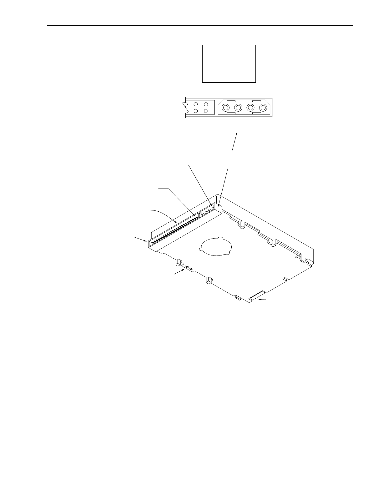
Barr acuda 4X L P roduct Manual, Rev. B 53
Pin 1
J1
Pin 1
Pin
1P
2P
3P
4P
Power
+12V
+12V ret
+ 5V ret
+ 5V
J1
4P 3P 2P 1P
DC Power
Connector
SCSI I/O Connector
J2
Figure 15. Physical interface for “N” model drives
J6
Page 64
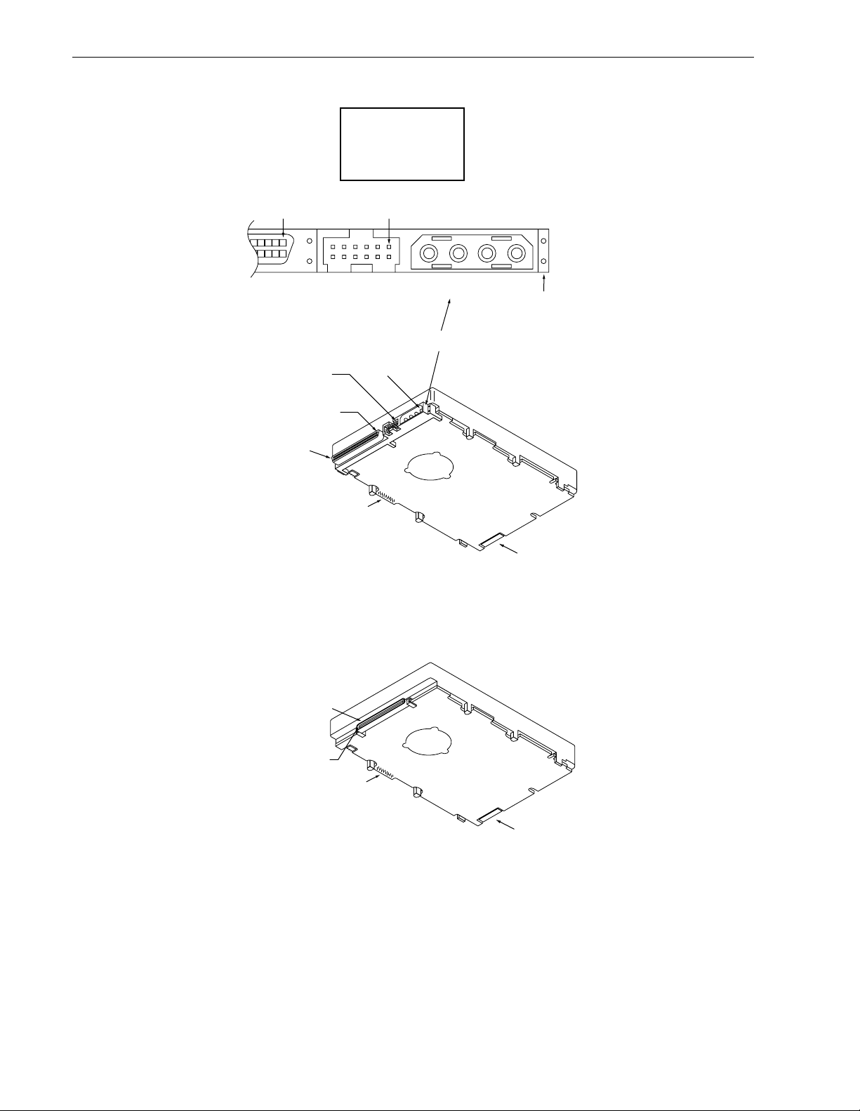
54 Barracuda 4XL Product Manual, Rev. B
J1
Pin 1
J1-Auxiliary
Pin 1A
68 Pin
SCSI I/O
Connector
J1
Pin 1
Pin
1P
2P
3P
4P
J1-Auxiliary
Pin 1A
Pin 1P
J2
Power
+12V
+12V ret
+ 5V ret
+ 5V
J1-DC Power
1P2P3P4P
PCB
J1-DC Power
Figure 16. Physical interface for “W” and “WD” model drives
J1
80 Pin SCSI I/O
and Power
Connector
Pin 1
J2
Note: See Tables 16 and 17 for DC power pin assignments.
Figure 17. Physical interface for “WC” and “DC” model drives
J6
J6
Page 65

Barr acuda 4X L P roduct Manual, Rev. B 55
9.6.2 SCSI interface physical description
The drives may be daisy-chained together or with other compatible SCSI devices. Both ends of the cable must
be terminated. The “N,” “W,” and “WC” model drives implement single-en ded drivers and receivers. All signals
are common bet ween all SCSI devices. The dr ive may be daisy-chained only with SCSI devices having the
same type drivers and receivers. Devices having single-ended interface circuits cannot b e on the s ame daisy
chain with devices having differential interface circuit. A maximum of 8 (“N” models) or 16 (“W” and “WC”) S CSI
devices (including the Host) may be daisy-chained together. The SCSI devices at both ends of the daisy chain
are to be terminated. Intermediate SCSI devices shall not be terminated (see Figure 18). Remove the terminator enable jumper TE on J2 select header (“N” and “W” models), or the external terminators (“WD” model) not
the terminator power source selector jumper TP (Figure 12).
“WC” and “DC” model d rives plug into PC B or bulkhead con nectors in the Host. They may be connected in a
daisy chain by the host backplane wiring or PCB circuit runs that have adequate DC current carrying capacity
to support the number of dr ives plugged into the PCB or bulkhead connect ors. A single 80 pin I/O connector
cable cannot suppor t the DC c urrent needs of s everal drives, so no daisy-chain cables beyond the bulkhead
connectors should be used. A single drive connec ted via a cable to a h ost 80 pin I/O c onnector is no t recommended.
9.6.3 SCSI interface cable requirements
In general, cables having the characteristic impedances given in Section 9.6.3.1 are not available; however,
impedances that are somewhat lower are satisfactory. A characteristic impedance as listed in Table 12 is recommended for unshielded flat cable or twisted pair ribbon cable. To minimize discontinuances and signal
reflections, cables of different impedances should not be used in the same bus. Implementations may require
trade-offs in shielding effectiveness, cable length, the number of loads, transfer rates, and cost to achieve satisfactory system operation. If shielded and unshielded cab les are mix ed within the same SCSI bus, the effect of
impedance mismatch must be carefully considered. Proper impedance matching is especially impor tant in
order to maintain adequate margin at FA S T SCSI transfer rates.
Model “N” drives use nonshielded cable connectors. A 50 conductor flat cable or 25 twisted pair cable shall be
used. A minimum conductor size of 28 AWG should be used to minimize noise effects.
Suggested nonshielded flat cable part numbers are:
Flat cable - 35M-3365-50 Twisted pair - Spectra Twist in flat 455-248-50
Model “W” and “WD” drives use nonshielded cable connectors. A 68 conductor flat cable or 34 twisted pair
cable shall be used with connectors listed in 9.6.4. A minimum cond uctor size of 28 AWG should be used to
minimize noise effects.
Suggested nonshielded flat cable part numbers are:
Flat cable - 35M-3365-68 Twisted pair - Spectra Twist in flat 455-248-68
For “WC” an d “DC” models:
The 80 pin connector option is intended for use on drives that plug directly into a PCB or wall/bracket mounted
connector in the host equipment. Installations with connectors on cables are not recommended.
Page 66
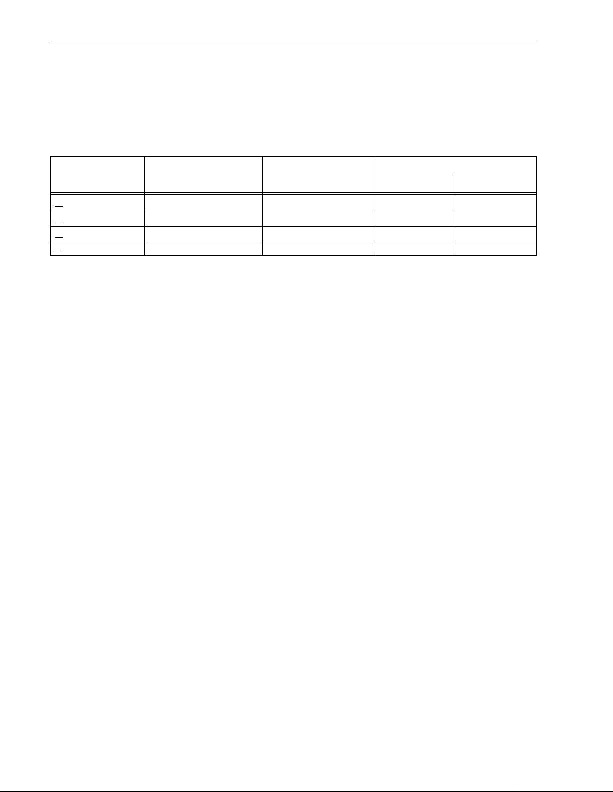
56 Barracuda 4XL Product Manual, Rev. B
9.6.3.1 Single-ended I/O circuits (“N” and “W” models)
The maximum total cable length allowed with drives having single-ended I/O driver and receiver circuits
depends on several factors. Table 12 lists the maximum lengths allowed for different configurations of drive
usage. These values are from the ANSI SCSI -3 Fast-20 (also called Ultra SCSI) sp ecification X3T10/1071D.
All device I/O lines must have equal to or less than 25 pf capacitance to ground, me asured at the beginn ing of
the stub.
T able 12: Cable characte ristics for singl e-ended circuits
Maximum number of
I/O transfer rate
<
10 M transfers/s 8 (reg. SCSI bus) 6 meters (19.7 ft.) 90 ± 6 Ohms 90 ± 10 Ohms
10 M transfers/s
<
20 M transfers/s 4 (reg./wide SCSI bus) 3 meters (9.8 ft.) [1] 90 ± 6 Ohms 90 ± 10 Ohms
<
<
20 M transfers/s 8 (reg./wide SCSI bus) 1.5 meters (4.9 ft.) [1] 90 ± 6 Ohms 90 ± 10 Ohms
devices on line
16 (wide SCSI bus) 6 meters (19.7 ft.) 90 ± 6 Ohms 90 ± 10 Ohms
Maximum cable
length allowed
Transmission line impedance
REQ/ACK Other signals
Notes:
[1] The spacing of devices on the mai nline SCSI bus shou ld be at least three tim es the stub length (def ined
below) to avoid clustering (Refer to Annex C of X3T10/1071D). Based on this criteria, it may be that 8
devices will not actually work on 1.5 meters of line ( .1 x 3 x 7 = 2.1 meters).
A stub length of no more than 0.1 meter (0.33 foot) is allowed off the mainline interconnection with any c onnected equipment. The stub length is measured from the transceiver to the connection to the mainline SCSI
bus.
Single-ended I/O pin assignments are shown in Tables 13, 14, and 16.
9.6.3.2 Differential I/O circuits (“WD” and “DC” models)
The maximum total ca ble length allowed with dri ves having differential I/O driver and receiver circuits is 2 5
meters (82 feet). Twisted-pair cable (either twisted-flat or discreet wire twisted pairs) should be used with differential I/O transceiver circuits. A stub length of no more than 0.2 meter (0.66 foot) is allowed off the mainline
interconnection with any connected equipment . The stub length is measured from the transce iver to the connection to the mainline SCS I bus. The spacing of devices on the main line SCSI bus should be at least three
times the stub length t o avoid clustering (Refer to Annex C of X 3T10 /1071D). This restr iction e as ily allows the
16 device IDs that the SCSI 16 bit wide bus can address. These values are from the ANSI SCSI-3 Fast-20
(also called Ultra SCSI) specification X3T10/1071D.
An ideal impedance match with cable terminators implies a cable characteristic impedance of 122 ohms. Differential I/O pin assignments are shown in Tables 15 and 17.
9.6.4 Mating connect o rs
Part numbers for the different type connectors that mate with the various Barracuda 4XL I/O connectors are
given in the following sections.
Page 67

Barr acuda 4X L P roduct Manual, Rev. B 57
9.6.4.1 Mating connectors for “N” models
The nonshielded cable connector shall be a 50 c onductor connect or consisting of two rows of 25 female contacts with adjacent contacts 0.1 inches (2.54 mm) apart.
Recommended mating flat cable connector par t numbers are:
Closed end 3M -3425-7000 W/O Strain Relief, No Center Key
(for cable 3M-3425-7050 With Strain Relief, No Center Key
ends)[1] Dupont-66900-290 With Strain Relief, With Center Key
Open end 3M-3425-6000 W/O Strain Relief, No Center Key
(In daisy chain)[1] 3M-3425-6050 With Strain Relief, No Center Key
Dupont-66900-250 With Strain Relief, With Center Key
[1] See Figure 18.
The drive device connector is a nonshielded 50 conductor connect or consisting of two rows of 25 male pins
with adjacent pins 0.1 inches (2.54 mm) apart. The connector is keyed (see Figure 19).
Mating panel mount connector: 3M-CHE-2050-J01A 10-KLE .
9.6.4.2 Mating connectors for “W” and “WD” models
The nonshielded cable connector shall be a 68 conductor connector consisting of two rows of 34 male contacts
with adjacent contacts 0.050 inches (1.27 mm) apar t.
Recommended mating flat cable connector par t numbers are:
Amp Model 786096-7 Female, 68-pin, panel mount
Amp Model 786090-7 Female, 68-pin, cable mount
Amp Model 749925-5 (0.050 inches (1.27mm, 50 mil) conductor centers, 28 or 30 AWG wire). Use
two, 34 conductor, 0.050 inches (1.27 mm, 50 mil) center flat cable with this
connector. This type connector can only be used on cable ends. [1]
Amp Model 88-5870-294-5 W/O Strain Relief, 0.025 68es (0.68 mm, 25 mil) conductor centers, 30 AWG
wire. Use either on cable ends or in cable middle section for daisy-chain
installat ion s [1].
Amp Model 1-480420-0 Power connector 4 circuit housing
Berg 69307-012 12-position, 2 x 6, 2 mm receptacle housing
[1] See Figure 18.
The drive device connector is a nonshielded 68 conductor connector consisting of two rows of 34 female pins
with adjacent pins 0.050 inches (1.27 mm) apar t. The c onnector is keyed by means of its shape (see Figure
20).
9.6.4.3 Mating connectors for “WC” and “DC” models
The nonshielded connector shall be an 80 conductor connector consisting of two rows of 40 contacts with adjacent contacts 0.050 inches (1.27 mm) apart. I/O connection using a cable is not recommended. The length and
size of the host equipment DC power carrying conductors from the DC power source to the host equipment 80
pin disk drive interface connector(s) should be strictly designed according to proper power transmission design
concepts. No possibility for the equipment user to att ach an 80 pin cable/connector should be allowed, since
the length of the DC power carrying conductors could not be controlled and therefore could become too long
for safe power transmission to the drive. Daisy-chain 80 conductor cables should especially not be allowed,
since the power-carrying co nductors on the 80 conduc tor interface were not intended to suppor t a series of
drives.
Small Form Factor Specification SSF-8046, Rev. 2.7 details mating requirements.
Page 68
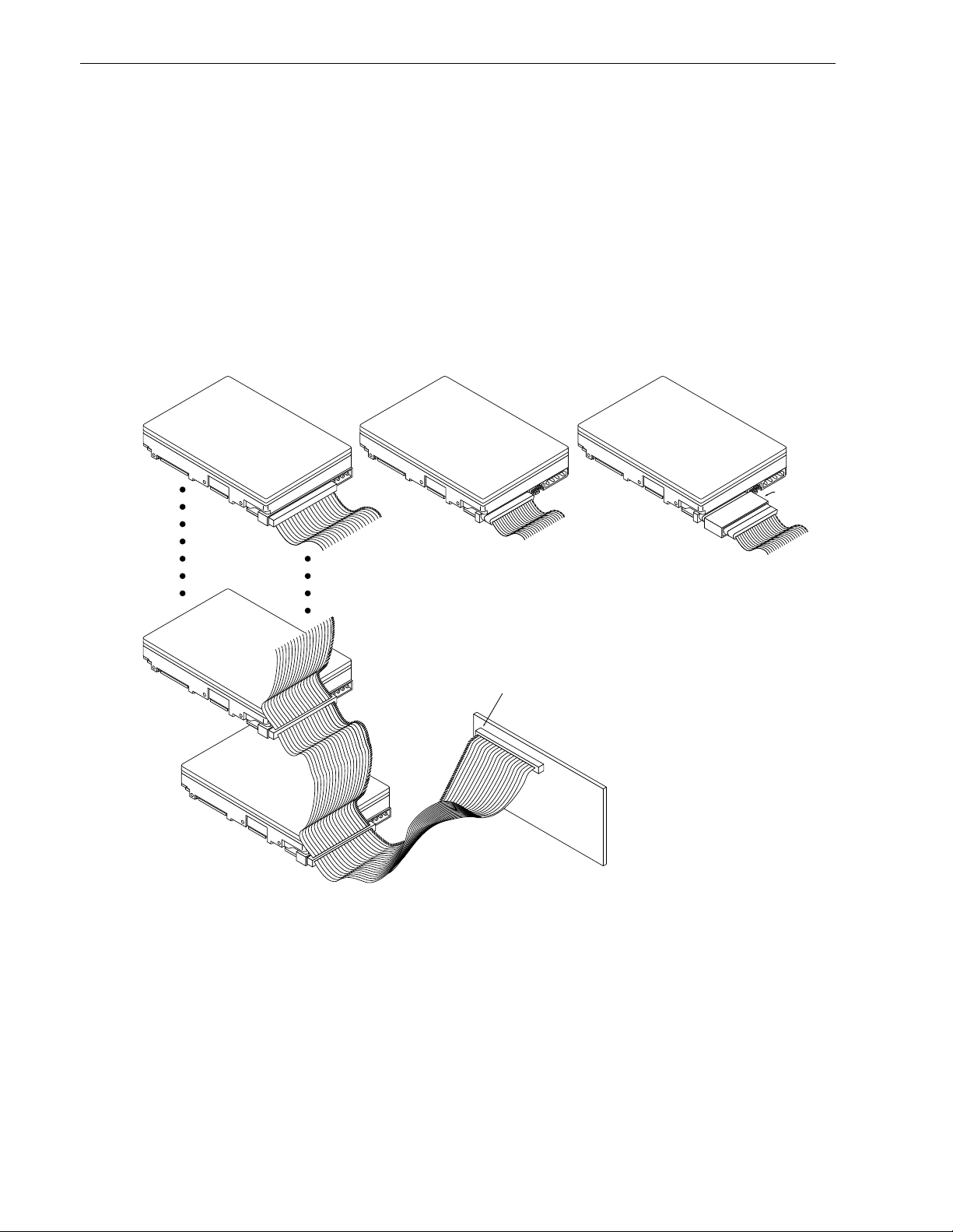
58 Barracuda 4XL Product Manual, Rev. B
Recommended mating 80-position PCB mount connectors:
Straight-in connector Hot Plug version (with ground guide- pin)
Seagate P/N: 77678703
Amp US P/N:
or
Amp US P/N:
or
2-557103-1
94-0680-02-1
2-557103-2
94-0680-02-2
787311-1 with polarization
787311-2 without polarization
Amp Japan P/N: 5-175475-9
Righ t -angle to PCB connectors
Seagate P/N: 77678559 Amp US P/N: 2-557101-1 Amp Japan P/N: 5-175474-9
For additional information call Amp. FAX service at 1-800-522-6752 .
“N” Model
Drive
[6]
SCSI ID 1
SCSI ID 0
“W” Model
Drive
[6] [6]
[1]
2 through X
SCSI devices [4]
[2]
[7]
Pin 1
(check your
adapter for Pin 1 location)
“WD” Model
Drive
Note. Do not mix “N” or “W”
drives with “WD” model
drives on the daisy chain.
SCSI ID 7 [5]
[1]
Host Adapter
PCB
Terminator
[7]
[2]
[3]
[1] Closed end type 50 pin connector used. Install terminator enable (TE) jumper.
[2] Open end type (in-line application) connector used. Remove terminator enable (TE) jumper.
[3] Host need not be on the end of the daisy chain. Another device can be on the end with the terminator, the
host having no terminator.
[4] Total interface cable length must not exceed that specified in Section 9.6.3.1 (including host adapter/initia-
tor). The cable length restriction limits the total number of devices allowed. See Table 12.
[5] SCSI ID7 has highest arbitration priority, ID0 has lowest for “N” models. For “W” models, priority is ID7 to
ID0, then ID15 to ID8 (ID 8 very lowest).
[6] Last drive on the daisy chain.
[7] Open-end type 68-pin connect or used. Terminators disabled on “W D” models. If end “WD” device, exter-
nal terminator and closed-end type 68-pin connecto r us ed. On “W” models, install term ina tor e nable (TE)
jumper plug. “N” and “W” drives do not require external terminators.
Figure 18. SCSI daisy-chain interface cabling for “N,” “W,” and “WD” model drives
Page 69
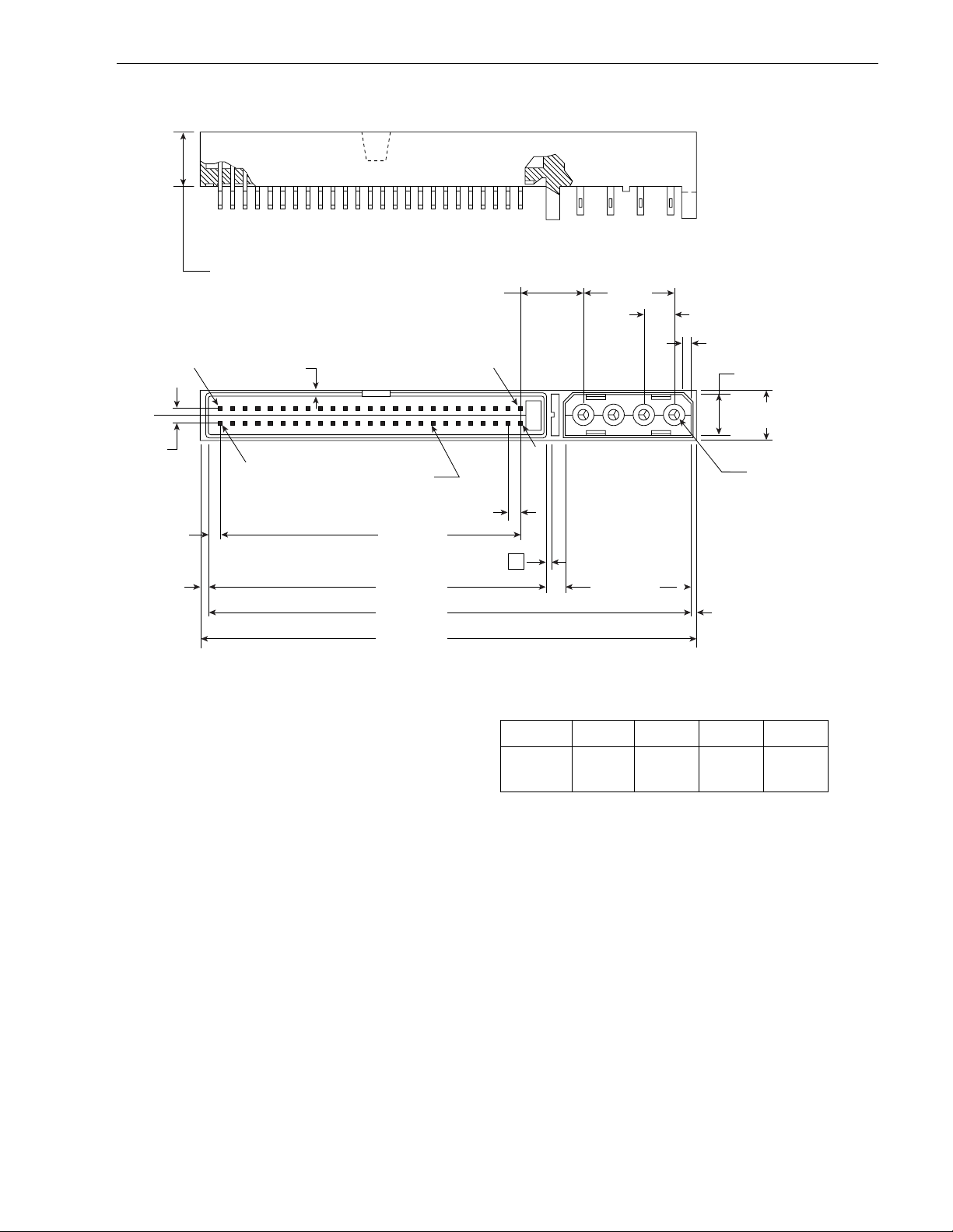
Barr acuda 4X L P roduct Manual, Rev. B 59
± .010
.370
C
L
.100
(2.54)
(4.06)
.051
(1.30)
.16
(9.398)
.037 Ref. Typ.
(.94)
Pin 50
.025
(.64)
Sq. Contact
50 Places
"D" ± .010
.045
(1.14)
"C" ± .010
"B" Ref.
"A" ± .010
.42
(10.67)
Pin 1Pin 49
.100
Typ.
(2.54)
Min. Typ. 3
Ref.
4
Pin
2
.60
(15.24)
3
.834 ± .010
(21.18)
12
.20
(5.08)
.065
(1.65)
(1.02)
Typ.
x 45
.26
(6.60)
.335 ± .010
(8.50)
.083
.040
Ref.
° Chamfer Typ.
Typ.
+.001
Dia.
–.002
(2.1)
Trifurcated Pin
(4 places)
No. Pos.50"A"
3.767
(95.68)
"B"
3.697
(93.90)
Figure 19. Nonshielded 50 pin SCSI de vice connector used on “N” model drives
"C"
2.720
(69.09)
"D"
2.400
(60.96)
Page 70
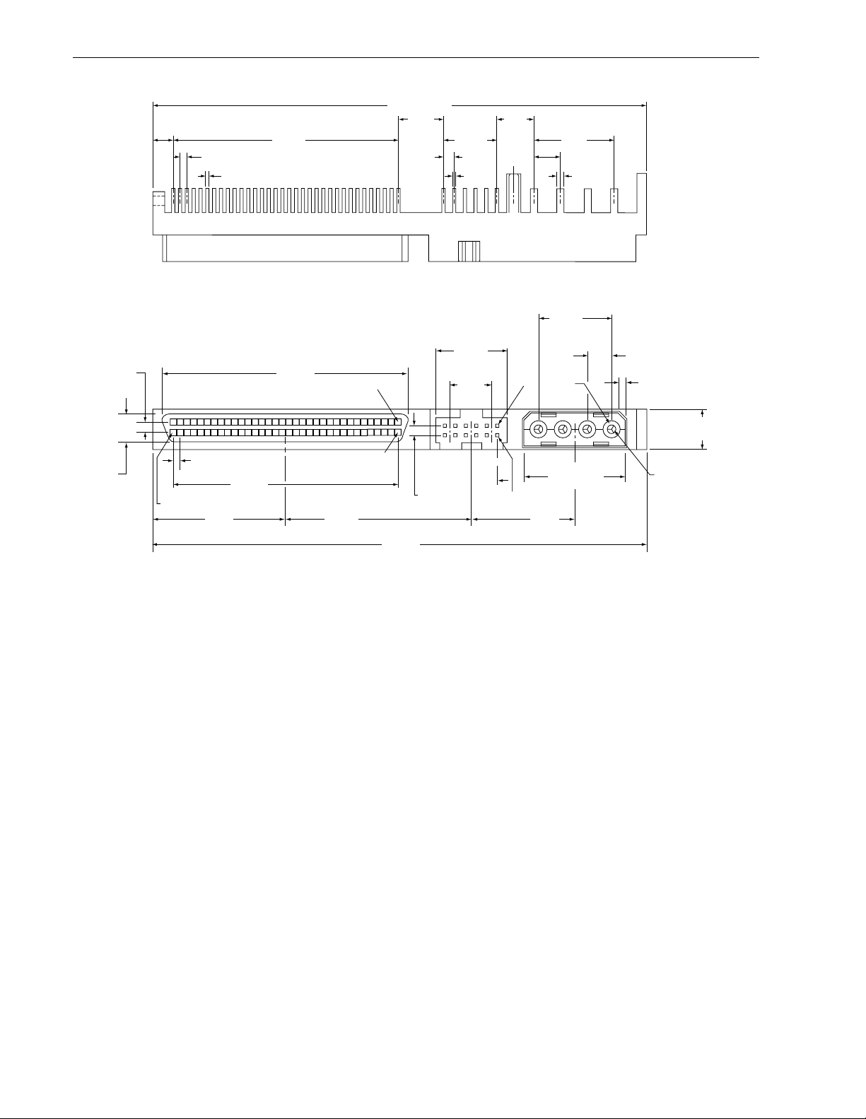
60 Barracuda 4XL Product Manual, Rev. B
3.650±.005
.100
(2.54)
.15 5
.050
.022
.346
1.650 .3937 .600
.519
1.816
(46.13)
Position 1
(13.18)
.315
(8.00)
.270
.0787 .200
.020 .047
.60
(15.24)
Pos.
1
Pos.
1
3
4
12
.20
(5.08)
.085
(2.16)
typ
x 45° chamfer
typ
.315 ± .010
(8.00)
.218
(5.54)
Pos. 68
.050
(1.27)
.980
(24.89)
1.650
(41.91)
1.368
(37.74)
Pos. 35
3.650
(92.71)
.0787
(2.00)
Pos.
2
.840 ± .005
.767
(19.48)
(21.34)
Figure 20. Non-shielded 68 pin SCSI device connector used on “W” and “WD” model drives
+.001
–.002
dia
.083
(2.1)
Trifurcated Pins
(4 places)
Page 71
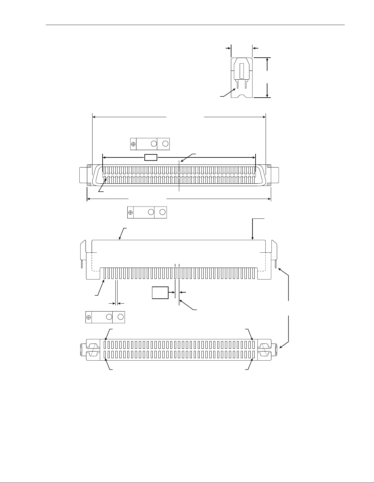
Barr acuda 4X L P roduct Manual, Rev. B 61
7.00
(.276)
Pin 1
51.17 ± 0.10
(2.251 ± 0.004)
0.15
MYM
(.006)
–Y–
62.15
(2.447)
Housing
0.15
(.006)
± 0.15
(± .006)
MYM
Grounding
57.87 ± 0.20
(2.278 ± 0.008)
Pins
C
of Datum Y
L
12.70
(.500)
End View
Front View
Insert mating
I/O connector
Top View
Contact
0.50
(.020)
0.3
MYM
(.012)
Pin 1 Pin 40
Pin 41 Pin 80
Figure 21. Non-shielded 80 pin SCSI “SCA-2” connector , used on “WC” and “DC” model drives
1.27
(.05)
Typ
C
of Datum Y
L
Grounding
Pins
Back View
Page 72

62 Barracuda 4XL Product Manual, Rev. B
T able 13: Model “N,” single ended I/O, 50 conductor, signal/contact assignments
Note. The minus sign next to the signal indicates asser ted state is the low voltage of the two levels used for
logic signals.
Signal
name [1]
Connec tor
contact
number [3]
Cable
conduct or
number [11]
Connector
contact
number [11]
Signal
name [1]
GND 1 1 2 2 –DB0
GND 3 3 4 4 –DB1
GND 5 5 6 6 –DB2
GND 7 7 8 8 –DB3
GND 9 9 10 10 –DB4
GND 11 11 12 12 –DB5
GND 13 13 14 14 –DB6
GND 15 15 16 16 –DB7
GND 17 17 18 18 –DBP
GND 19 19 20 20 GND
GND 21 21 22 22 GND
GND 23 23 24 24 GND
NC [10] 25* 25 26 26 TERMPWR
GND 27 27 28 28 GND
GND 29 29 30 30 GND
GND 31 31 32 32 –A TN
GND 33 33 34 34 GND
GND 35 35 36 36 –BSY
GND 37 37 38 38 –ACK
GND 39 39 40 40 –RST
GND 41 41 42 42 –MSG
GND 43 43 44 44 –SEL
GND 45 45 46 46 –C/D
GND 47 47 48 48 –REQ
GND 49 49 50 50 –I/O
*CAUTION: Connector contact 25 must not be connected to ground at the host end of the cable. If the I/O
cable should accidently be plugged in upside down, ter m ina tor power on pin 26 will be shor t ed t o
ground.
Note. See page following Table 17.
Page 73
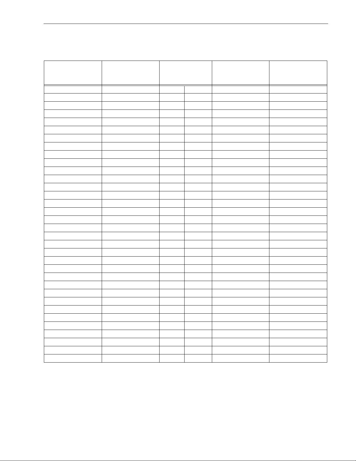
Barr acuda 4X L P roduct Manual, Rev. B 63
T able 14: “W” models single ended I/O cable 68 conductor signal/contact assignments
Note. The minus sign next to the signal indicates asser ted state is the low voltage of the two levels used for
logic signals
Signal
name [1]
Connector
contact
number [3]
Cable
conductor
number [2]
Connector
contact
number [3]
Signal
name [1]
GND 1 1 2 35 –DB12
GND 2 3 4 36 –DB13
GND 3 5 6 37 –DB14
GND 4 7 8 38 –DB15
GND 5 9 10 39 –DBP1
GND 6 11 12 40 –DB0
GND 7 13 14 41 –DB1
GND 8 15 16 42 –DB2
GND 9 17 18 43 –DB3
GND 10 19 20 44 –DB4
GND 11 21 22 45 –DB5
GND 12 23 24 46 –DB6
GND 13 25 26 47 –DB7
GND 14 27 28 48 –DBP
GND 15 29 30 49 GND
GND 16 31 32 50 GND
Ter mPwr 17 33 34 51 TermPwr
Ter mPwr 18 35 36 52 TermPwr
Reserved 19 37 38 53 Reserved
GND 20 39 40 54 GND
GND 21 41 42 55 –ATN
GND 22 43 44 56 GND
GND 23 45 46 57 –BSY
GND 24 47 48 58 –ACK
GND 25 49 50 59 –RST
GND 26 51 52 60 –MSG
GND 27 53 54 61 –SEL
GND 28 55 56 62 –C/D
GND 29 57 58 63 –REQ
GND 30 59 60 64 –I/O
GND 31 61 62 65 –DB8
GND 32 63 64 66 –DB9
GND 33 65 66 67 –DB10
GND 34 67 68 68 –DB11
Note. See page following Table 17.
Page 74

64 Barracuda 4XL Product Manual, Rev. B
T able 15: “WD” models differential cable 68 conduct or signal/pin assignm ents (Nonshielded connector)[13]
Note. The minus sign next to the signal indicates asser ted state is the low voltage of the two levels used for
logic signals.
Signal
name [1]
Connector
contact
number [3]
Cable
conductor
number [2]
Connector
contact
number [3]
Signal
name [1]
+DB12 1 1 2 35 –DB12
+DB13 2 3 4 36 –DB13
+DB14 3 5 6 37 –DB14
+DB15 4 7 8 38 –DB15
+DBP1 5 9 10 39 –DBP1
GND 6 11 12 40 GND
+DB0 7 13 14 41 –DB0
+DB1 8 15 16 42 –DB1
+DB2 9 17 18 43 –DB2
+DB3 10 19 20 44 –DB3
+DB4 11 21 22 45 –DB4
+DB5 12 23 24 46 –DB5
+DB6 13 25 26 47 –DB6
+DB7 14 27 28 48 –DB7
+DBP 15 29 30 49 –DBP
DIFFSENS 16 31 32 50 GND
Ter mPwr 17 33 34 51 TermPwr
Ter mPwr 18 35 36 52 TermPwr
Reserved 19 37 38 53 Reserved
+ATN 20 39 40 54 –ATN
GND 21 41 42 55 GND
+BSY 22 43 44 56 –BSY
+ACK 23 45 46 57 –ACK
+RST 24 47 48 58 –RST
+MSG 25 49 50 59 –MSG
+SEL 26 51 52 60 –SEL
+C/D 27 53 54 61 –C/D
+REQ 28 55 56 62 –REQ
+I/O 29 57 58 63 –I/O
GND 30 59 60 64 GND
+DB8 31 61 62 65 –DB8
+DB9 32 63 64 66 –DB9
+DB10 33 65 66 67 –DB10
+DB11 34 67 68 68 –DB11
See page following T able 17.
Page 75

Barr acuda 4X L P roduct Manual, Rev. B 65
T able 16: “WC” models single ended I/O, 80 conductor cable signal/contact assignments
Note. The minus sign next to the signal indicates asser ted state is the low voltage of the two levels used for
logic signals
Connector
Signal
name [1]
contact
number [3]
Signa l
number [3]
Contact
name[1]
12 V CHARGE 1 41 12 V GND
12 V 2 42 12 V GND
12 V 3 43 12 V GND
12 V 4 44 MATED 1
NC [10] 5 45 NC [10]
NC [10] 6 46 GND [8]
–DB11 7 47 GND
–DB10 8 48 GND
–DB9 9 49 GND
–DB8 10 50 GND
–I/O 11 51 GND
–REQ 12 52 GND
–C/D 13 53 GND
–SEL 14 54 GND
–MSG 15 55 GND
–RST 16 56 GND
–ACK 17 57 GND
–BSY 18 58 GND
–ATN 19 59 GND
–DBP 20 60 GND
–DB7 21 61 GND
–DB6 22 62 GND
–DB5 23 63 GND
–DB4 24 64 GND
–DB3 25 65 GND
–DB2 26 66 GND
–DB1 27 67 GND
–DB0 28 68 GND
–DP1 29 69 GND
–DB153070GND
–DB143171GND
–DB133272GND
–DB123373GND
+5 V3474MATED 2
+5 V35755 V GND
+5 V CHARGE 36 76 5 V GND
NC [10] 37 77 ACTIVE LED OUT [4] [9]
RMT-START [5] [9 ] 3 8 78 D LYD-START [6] [9 ]
SCSI ID (0) [7] [9] 39 79 SCSI ID (1) [7] [9]
SCSI ID (2) [7] [9] 40 80 SCSI ID (3) [7] [9]
Note. See page following Table 17.
Page 76
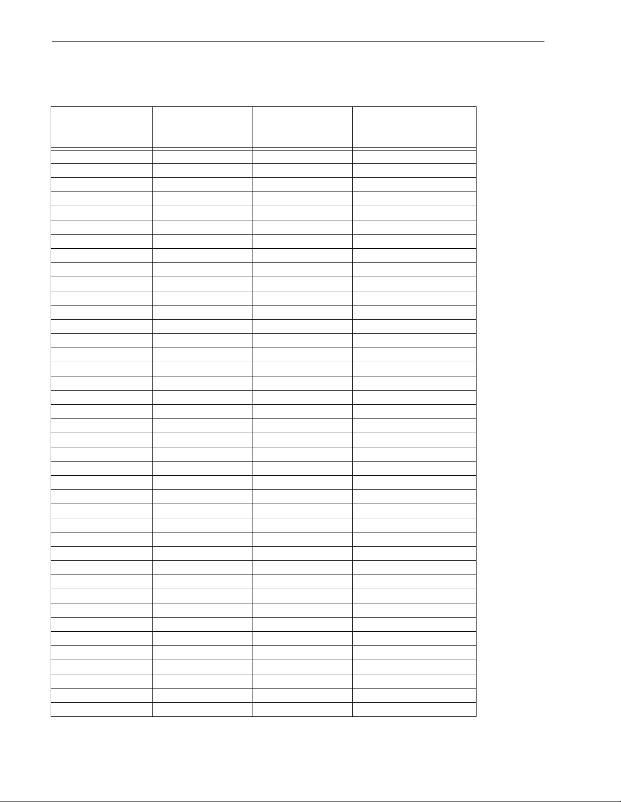
66 Barracuda 4XL Product Manual, Rev. B
T able 17: “DC” differential models, 80 pin I/O connector pin assignment s (Non-shielded connector) [13]
Note. The minus sign next to the signal indicates asser ted state is the low voltage of the two levels used for
logic signals
Connector
Signal
name [1]
contact
number [3]
Signa l
number [3]
Contact
name[1]
12 V CHARGE 1 41 12 V GND
12 V 2 42 12 V GND
12 V 3 43 12 V GND
12 V 4 44 MATED 1
NC [10] 5 45 NC [10]
NC [10] 6 46 DIFFSENS [8]
–DB11 7 47 +DB11
–DB10 8 48 +DB10
–DB9 9 49 +DB9
–DB8 10 50 +DB8
–I/O 11 51 +I/O
–REQ 12 52 +RE Q
–C/D 13 53 +C/D
–SEL 14 54 +SEL
–MSG 15 55 +MSG
–RST 16 56 +RS T
–ACK 17 57 +ACK
–BSY 18 58 +BSY
–ATN 19 59 +ATN
–DBP 20 60 +DBP
–DB7 21 61 +DB7
–DB6 22 62 +DB6
–DB5 23 63 +DB5
–DB4 24 64 +DB4
–DB3 25 65 +DB3
–DB2 26 66 +DB2
–DB1 27 67 +DB1
–DB0 28 68 +DB0
–DP1 29 69 +DP1
–DB153070+DB15
–DB143171+DB14
–DB133272+DB13
–DB123373+DB12
+5 V3474MATED 2
+5 V35755 V GND
+5 V CHARGE 36 76 5 V GND
NC [10] 37 77 ACTIVE LED OUT [4] [9]
RMT-START [5] [9 ] 3 8 78 D LYD-START [6] [9 ]
SCSI ID (0) [7] [9] 39 79 SCSI ID (1) [7] [9]
SCSI ID (2) [7] [9] 40 80 SCSI ID (3) [7] [9]
Note. See page following this table.
Page 77

Barr acuda 4X L P roduct Manual, Rev. B 67
Notes [ ] for Tables 13 through 17.
[1] See Section 9.7.1 or 9.6.4.2 for detailed electrical characteristics of these signals.
[2] The conductor number refers to the conductor position when using 0.025-inches (0.635 mm ) centerline
flat ribbon cable. Other cables types may be used to implement equivalent contact assignments.
[3] Connector contacts are on 0.050 inches (1.27 mm) centers.
[4] Front panel LED signal; indicates drive activity for host front panel hard drive activity indicator.
[5] Asserted by host to enable Motor Start option (enables star t ing motor via SC SI bus command).
[6] Asserted by host to enable Delay ed Motor St art option (motor starts at power on or after a delay of 12 sec-
onds times drive ID). This and [3] above are mutually exclusive options.
[7] Binary code on A3, A2, A1 and A0 asser t ed by host to set up SCSI bus ID in drive.
[8] GND provides a means for differential devices to detect the presence of a single ended device on the bus.
[9] Signals [4] through [7] are used in place of installing jumpers and cables on option select connectors J2
and J6. See Section 8.1.1 notes.
[10] “NC” means no connection.
[11] The conductor number refers to the conductor position (right to left in Figure 18) when using 0.050 inches
(1.27 mm) centerline flat ribbon cable. Other cable types may be used to impl ement equivalent contact
assignments.
[12] Connector contacts are on 0.100 inches (2.54 mm) centers.
[13] 8 bit devices which are connected to the 16 data bit differential I/O shall leave the following signals open:
–DB12 –DB13 –DB14 –DB15 –DBP1 –DB8 –DB9 –DB10 –DB11.
+DB12 +DB13 +DB14 +DB15 +DBP1 +DB 8 +DB 9 +DB 10 +DB11.
All other signals shall be connected as defined.
Page 78
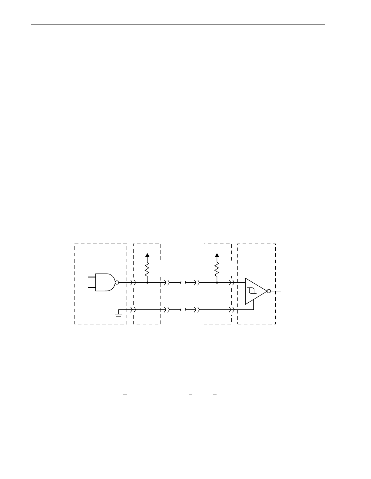
68 Barracuda 4XL Product Manual, Rev. B
9.7 Electrical description
“N” and “W” models use single-ended interface signals. These signals must be terminated with 110-ohm active
termination circuits at each end of t he total cable. Single-ended circuits use open col lector or three state drivers. All of these models can be configured to provide the SCSI termination.
“WD” models use differential interface signals and each of these must be ter minated at each end of the total
cable with 330 ohms to +5V and 330 ohms to ground with 150 ohms between each differential pair. All I/O circuits are open collector, three state drivers. Differential I/O drives are shipped without terminators. These
drives have no provisions for adding terminator sockets on the PCB. This means some method of external termination must be provided by the user when termination is required.
“WC” and “DC” models use the single connection attachment (SCA) connector. This 80-pin connector is
designed to plug directly into a back panel or plane. No external cables are required. Active terminators on the
back panel must be provided by the user. This connector is not recommended where cabling is required.
9.7.1 Single-ended drivers/receivers
For “N,” “W,” and “WC” models which use s ingle-ended drivers and receivers, typical circuits are shown in Figure 22. Terminator circuits (Note [1]) are to be enabled only when the disc drive i s first or l ast in the daisy c hain.
Transmitter characteristics
Single-ended drives use an ANSI SCSI compatible open collector single-ended driver. This driver is capable of
sinking a current of 48 mA with a low level output voltage of 0.4 volt.
Receiver characteristics
Single-ended drives use an ANSI SCSI single-ended receiver with hysteresis gate or equivalent as a line
receiver.
Line Driver
Transmitter
(or transceiver)
[2]
Figure 22. Single-ended transmitters and receivers
TP TP
[4]
110
[1]
Ohm
[3]
Flat
Cable
Pair
Line Receiver
[4]
[1]
Ohm
Receiver
110
[2]
Notes.
[1] Part of active terminator circuits. Non-removable LSI terminators, enabled in the drive (models “N” and
“W” only) with jumper plug TE when it is first or l ast in t he dai sy cha in. Interface signals levels and logical
sense at the drive I/O connector are defined as follows:
Logic level Driver output Receiver input
NEGATED (0) >
ASSERTED (1) <
2.5 V: <5.25 V >2.0 V: <5.25 V
0.4 V: >0.0 V <0.8 V : >0. 0 V
The difference in the voltages between input and output signals is due to the losses in the cable.
[2] ANSI SCSI compatible circuits.
[3] Total interface cable length should not exceed that specified in Section 9.6.3.1.
[4] Source of drive terminator power is an active circuit which has an input source voltage selected by jumper
plug TP. See Figure 12. Applies to “N” and “W” models.
Page 79

Barr acuda 4X L P roduct Manual, Rev. B 69
9.7.2 Differential drivers/receivers
Differential drivers and receivers are used by the “WD,” and “DC” models. Typical circuits are shown in Figure
23. The drive has no provisions for terminator circuits on differential I/O drives.
Differential signals
All differential interface signals consist of two lines denoted +SIGNAL and –SIGNAL. A signal is true when
+SIGNAL is more positive than –SIGNAL, and a signal is false when –SIGNAL is more positive than +SIGNAL.
Drive user or systems integrator must provide some external means of termination.
Output characteristics
Each signal driven by differential interface drives shall have t he following output characteristics when measured
at the disc drive SCSI connector:
Low-lev el output voltage* = 2.0 V maximum at Low-level output current = 55 milliamps.
High-level output voltage* = 3.0 V minimum at High-level output current = –55 milliamps
Differential voltage = 1.0 V minimum with common-mode voltage ranges from –7 V dc to +12 V dc.
*These voltages shall be measured between the output terminal and the SCSI device’s logic ground reference.
The output characteristics shall additionally conform to EIA RS-485-1983.
Input characteristics
Each signal received by differential interface drives shall have the following input characteristics when measured at the disc drive SCSI connector:
Input current on either input = +2.0 milliamps maximum (includes both receivers and passive drivers).
This requirement shall be met with the input voltage varying between –7 V dc and +12 V dc, with power on or
off, and with the hysteresis equaling 35 mv, minimum .
The input characteristics shall additionally conform to EIA RS-485-1983.
Page 80
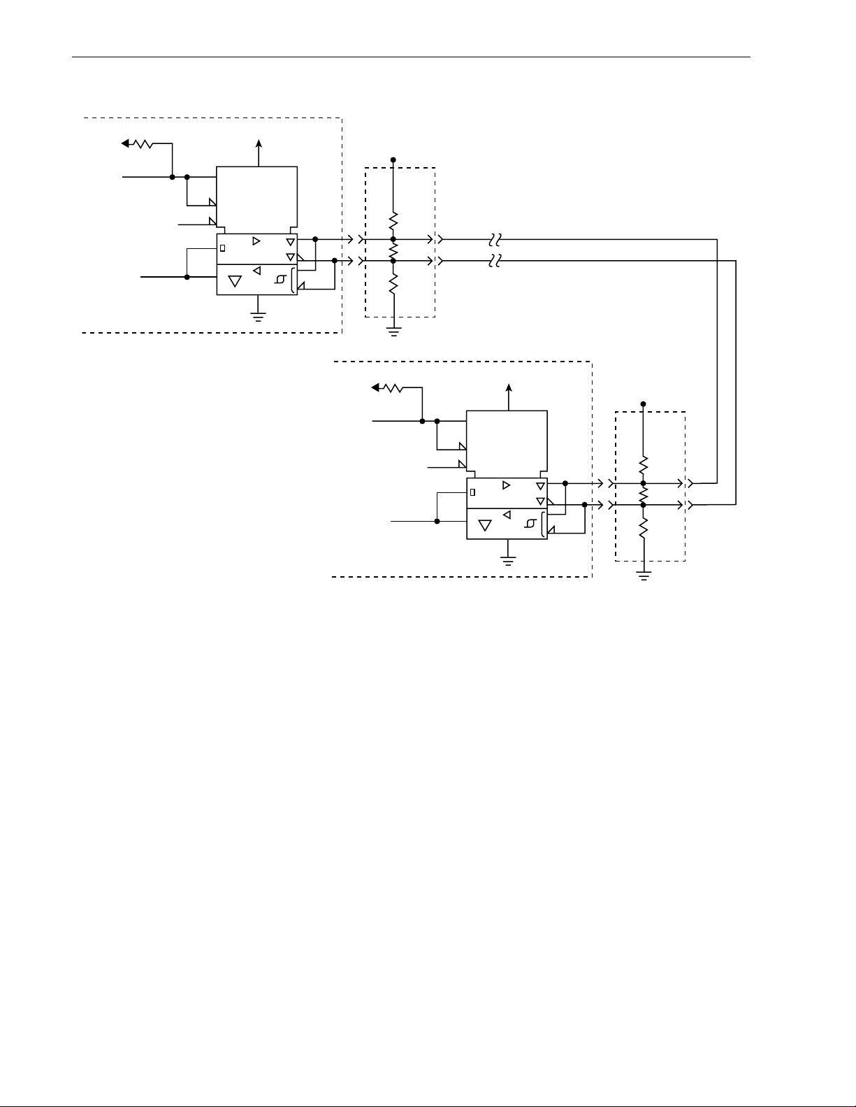
70 Barracuda 4XL Product Manual, Rev. B
+5V
5.6K
Transmit/Receive
Enable [1]
DIFFSENS [6]
Transmit or
Receive
Signal [2]
SCSI Device at Beginning of I/O Cable
(usually Host Adaptor/Initiator)
+5V
TE
LSI
XCVR
RE
Disable
R2
Term
[5]
Power
330
150
Ohm
330
[7]
[4]
+5V
TE
LSI
XCVR
RE
Disable
R2
[3]
1
1
Twisted or Flat
Cable Pair
Term
Power
330
Ohm
150
Ohm
330
Ohm
[5]
[4]
Ohm
1
1
Ohm
+5V
5.6K
Transmit/Receive
Enable [1]
DIFFSENS [6]
Transmit or
Receive
Signal [2]
SCSI Device at End of I/O Cable
(Drive/Target)
[7]
Notes.
[1] Positive Logic Enables Transmitter (+5 V = Asser ted)
Negative Logic Enables Receivers (0 V = Asser ted)
[2] Negative Logic Signal (0 V = Asserted)
[3] Total interface cable length should not exceed value given in Section 9.6.3.2 from first SCSI device at
beginning to end of daisy chain. See Section 9.7.2 for signal characteristics.
[4] I/O Line terminators. If SCSI device is a Seagate di sc dr ive, termi nators an d a pla ce to pl ug t hem in must
be provided external to the drive by user, systems integrator or host equipment manufacturer where
needed. The drive has no terminators and there are no provisions on the drive for terminator installation.
[5] Arrangements for connecting terminator power to the terminators must be made by the systems designer.
As a help, drive +5 V power is made available on SCSI bus (“N,” “W, ” and “WD” models) for powering
external terminators if the drive option s elect header jumpe r TP (Figure 7d) is installed in rightmost pos i-
tion “TP.” See pin assignment Tables 14 and 15 for pins assigned to terminator power.
[6] SCSI I/O line (pin 21) disables I/O circuits if single-ended cable plugged in or cable plugged in upside
down.
[7] SCSI I/O cable ground. See Tables 14 and Table 17.
Figure 23. Typical differential I/O line transmitter/receiver and external terminators
Page 81

Barr acuda 4X L P roduct Manual, Rev. B 71
9.8 Terminator requirements
Internal disc dr ive I/O termination (provided onl y in model “N” and “W” d rives single ended I/O mo del drives)
consists of active circuits in an LSI modul e that is per manently m ounted on the P CB. All single in itiator/single
target (non-daisy-chain) appl ications require t hat the Initiator and disc dr ive be termi nated. Daisy-c hain appl ications require that only the units at each end of the daisy chain be ter minated. All other peripherals on the
chain must not be terminated. (See Figure 18).
Note. Remove drive terminator enabling jumper TE where terminators are not required. Removal of termina-
tor power source selection jumper TP (see Figure 12) does not disconnect the terminator resistors
from the circuit.
It is highly recommended that ANSI SCSI-2 Standard’s Alternat ive 2 termination (active termination) be used
for applications with single-ended (“N” and “W” models), especially if the bus will be operated at transfer rates
above 5 Mbytes/sec. The “N” and “W” models provide on-board active termination that can be disabled by
removal of the enable jumper TE (see Figure 12).
Note. ACTIVE TERMINATORS ARE HIGHLY RECOMMENDED FOR USE IN THE DAISY CHAIN AS
DESCRIBED ABOVE. ACTIVE AND PASSIVE TERMINATORS SHOULD NOT BE MIXED ON THE
SAME SCSI BUS.
Drive models “WD,” “WC,” and “DC” do not have internal terminators available. The user, systems integrator or
host equipment manufacturer must provide a terminator arrangement external to the drive. For “WD” models,
terminator modules can be purchased that plug between the S CS I I/O cable an d the drive I/O connector or on
the end of a short I/O cable stub extending past the last cable connector.
9.9 Terminator power “N” and “W” model drives
You can configure t erminator power in four different ways. See Section 8.1 for illustrations that show how to
place jumpers enabling each of the following terminator power configurations:
1. Dri ve accepts terminat or power through SCSI bus pins:
“N” models Pin 26
“W” models Pins 17, 18, 51, and 52
2. Drive supplies power to the SCSI bus.
3. Drive provides terminator power f or optional internal terminator resistors using the drive’s power connector.
4. Dri ve provides power to its own terminators and to the SCSI bus terminator power line.
SCSI devices providing terminator power (TERMPWR) must have the following characteristics:
8-bit SCSI V TERM = 4.25 V to 5.25 V
800 mA minimum source drive capability
1.0 A maximum
16-bit SCSI V TERM = 4.25 V to 5.25 V
1,500 mA minimum source drive capability
3.0 A maximum
“WD” model dri v es
You can configure terminato r power from the drive to the SCSI bus or have the host adaptor or other device
supply terminator power to the external termi nator. See Section 8.1 for illustrations that show how to place
jumpers for this configuration.
“WC” and “D C ” mode l dri ve s
These drives cannot furnish term inator power because no conductors in the 80-pin I/O connector are devoted
to terminator power.
Page 82

72 Barracuda 4XL Product Manual, Rev. B
9.10 Disc dr ive SCSI tim ing
T able 18: Disc drive SCSI timing
Description
Waveform
symbol [1]
Wavef orm
table [1] Typical timing
Target Select Time (no Arbitration) [4] T00 N/A <2 µs
Target Select Time (with Arbitration) [4] T01 4.5-1,2 <2 µs
Target Select to Command T02 4.5-1 3.77 µs
Target Select to MSG Out T 03 4.5-2 1.57 µs
Identify MSG to Command T04 4.5-3 3.36 µs
Command to Status T05 4.5-5 Command Dependent
Command to Data (para. In) T06 4.5-9 Command Dependent
Command to Data (para. Out) T07 4.5-10 Command Dependent
Command to Data (Write to Data Buffer) T08 4.5-10 Command Dependent
Command to Disconnect MSG T09 4.5-6 Command Dependent
Disconnect MSG to Bus Free T10 4.5-6,14 0.52 µs
Disconnect to Arbitration (for Reselect)
T11 4.5-6 Command Dependent
This measures disconnected CMD overhead
Target win Arbitration (for Reselect) T12 4.5-7 3.00 µs
Arbitration to Reselect T13 4.5-7 1.60 µs
Reselect to Identify MSG In T14 4.5-7 1.39 µs
Reselect Identify MSG to Status T15 4.5-8 Command Dependent
Reselect Identify MSG to Data (media) T16 4.5-11 Command Dependent
Data to Status T17 4.5-15 Command Dependent
Status to Command Complete MSG T18 4.5-5,8,15 0.98 µs
Command Complete MSG to Bus Free T19 4.5-5,8,15 0.51 µs
Data to Save Data Pointer MSG T20 4.5-14 4.00 µs
Save Data Pointer MSG to Disconnect MSG T21 4.5-14 0.79 µs
Command Byte Transf er T22 4.5-4 0.04 µs
Next Command Byte Access : 4.5-4
Next CDB Byte Access (Byte 2 of 6) T23.6.2 4.5-4 0.58 µs
Next CDB Byte Access (Byte 3 of 6) T23.6.3 4.5-4 0.12 µs
Next CDB Byte Access (Byte 4 of 6) T23.6.4 4.5-4 0.12 µs
Next CDB Byte Access (Byte 5 of 6) T23.6.5 4.5-4 0.12 µs
Next CDB Byte Access (Byte 6 of 6) T23.6.6 4.5-4 0.12 µs
Next CDB Byte Access (Byte 2 of 10) T23.10.2 4.5-4 0.59 µs
Next CDB Byte Access (Byte 3 of 10) T23.10.3 4.5-4 0.11 µs ±1 µs
Next CDB Byte Access (Byte 4 of 10) T23.10.4 4.5-4 0.12 µs ±1 µs
Next CDB Byte Access (Byte 5 of 10) T23.10.5 4.5-4 0.11 µs ±1 µs
Next CDB Byte Access (Byte 6 of 10) T23.10.6 4.5-4 0.11 µs ±1 µs
Next CDB Byte Access (Byte 7 of 10) T23.10.7 4.5-4 0.13 µs ±1 µs
Next CDB Byte Access (Byte 8 of 10) T23.10.8 4.5-4 0.12 µs ±1 µs
Next CDB Byte Access (Byte 9 of 10) T23.10.9 4.5-4 0.12 µs ±1 µs
Next CDB Byte Access (Byte 10 of 10) T23.10.10 4.5-4 0.12 µs ±1 µs
Page 83

Barr acuda 4X L P roduct Manual, Rev. B 73
T able 18: Disc drive SCSI timing (Contin ued)
Description
Waveform
symbol [1]
Wavef orm
table [1] Typical timing
Data In Byte Transfer (parameter) T24 4.5-12 0.04 µs
Data Out Byte T ransfer (parameter) T25 4.5-13 0.04 µs
Next Data In Byte Access (parameter) T26 4.5-12 0.12 µs
Next Data Out Byte Access (parameter) T27 4.5-13 0.12 µs
Data In Byte Transfer (media) [2] T28 4.5-12 0.0 4 µs
Data Out Byte T ransfer (media) [2] T29 4.5-13 0.04 µs
Next Data In Byte access (media [2] T30 4.5-12 0.12 µs
Next Data Out Byte access (media [2] T31 4.5-13 0.12 µs
MSG IN Byte Transfer T32 4.5-5,7,8,14,15 0.04 µs
MSG OUT Byte Transfer T33 4.5-2 0.04 µs
STATUS Byte Transfer T34 4.5-5,8,15 0.04 µs
Synchronous Data T ransfer Characteristics:
Request Signal Tr ansf er Period [3] – – various
Notes.
[1] See
SCSI Interface Product Manual
(part number 77738479), Section 4.5
[2] Maximum SCSI asynchronous interface transfer rate is given in Section 4.2.3 of this manual.
[3] Synchronous Transfer Period is determined by negotiations between an Initiator and a Dri ve. The Drive is
capable of setting periods as given in Section 9.5. See also Sections 3.1.5.2 and 3.5.3.2 of the
face Product Manual
General timing diagrams for SCSI interface operation are shown in the
for a description of synchronous data transfer operation.
SCSI Interface Product Manual
SCSI Inter-
, Section
4.5. The specific timing values that apply to this drive are listed in Table 18.
Page 84

Page 85

Barr acuda 4X L P roduct Manual, Rev. B 75
10.0 Seagate technical support services
If you need assistance installing your drive, consult your dealer. Dealers are familiar with their unique system
configurations and can help you with s ystem conf licts an d ot her technical issues. If you need additional assistance with your Seagate
listed below.
SeaFONE® 1-800-SEAGATE
Seagate’s 800 number (1-800-732-4283) allows toll-free access to automated self-help services, providing
answers to commonly asked questions, troubleshooting tips, and specifications for disc drives and tape drives.
This service is available 24 hours daily and requires a touch-tone phone. International callers can reach this
automated self-help service by dialing 408-456-4496.
Online services
Using a modem, you can obtain troubleshooting tips, free utility programs, dr ive specifi cations and jumper settings for Seagate’s entire product line. You can also download software for installing and analyzing your drive.
SeaNET
You can obtain technical information about Seagate produ cts over the Internet from Seagate’s World Wide
Web home page (http://www.seagate.com) or Seagate’s ftp server (ftp://ftp.seagate.com). You can also
send E-mail with your questions to DiscSupport @ Seagate.com or TapeSupport @ Seagate.com.
Seagate CompuServe forum
Online technical suppor t for Seagate products is available on CompuSer ve. To acces s our technical support
for u m, typ e
can type questions or browse through previous questions and answers on the forum messages.
SeaBOARD
SeaBOARD is a computer bulletin board system that contains information about Seagate disc and tape drive
products and is available 24 hours daily. Set your communication s software to eight data bits, no parity, an d
one stop bit (8-N-1).
Location Phone number
Australia 61-2-9756-2359
England 44-1628-478011
France 33 1-48 25 35 95
Germany 49-89-140-9331
Taiwan 886-2-719-6075
Thailand 66 2-531-8111
USA Disc: 405-936-1600; Tape: 405-936 -1630
™
go seagate
®
®
drive or other Seagate products, use one of the Seagate technical support services
. This forum provides information similar to that found on SeaBOARD. In addition, you
FAX services
SeaFAX
You can use a touch-tone telephone t o access Seag ate’s automated FAX system to receive technical suppor t
information by return FA X. This ser vice is available 24 hours daily.
Location Phone number
Australia 61-2-9756-5170
England 44-1628-894084
USA Disc: 405-936-1620; Tape: 405-936 -1640
Seagate technical support FAX
You can FAX questions or comments to technical supp ort specialists 24 ho urs daily. Responses are sent during business hours.
Location Phone number
Australia 61-2-9725-4052
England 44-1628-890660
France 33 1-46 04 42 50
Germany 49-89-1430-5100
®
Page 86

76 Barracuda 4XL Product Manual, Rev. B
Location Phone number
Hong Kong 852-2368 7173
Japan 81-3 -5462-2979
Korea 82-2-556-7294/4251
Singapore 65-488-7528
Taiwan 886-2-715-2923
USA Disc: 405-936-1685; Tape: 405-936 -1683
Direct-support services
Seagate technical support
For one-on-one help, you can talk to a technical su pport specialist du ring local busines s hours. Before calling,
xxxx
note your system configuration and drive model number (ST
Location Phone number
A.M
Australia 61-2-9725-3366 (9:00
England 44-1628-894083 (10:00
France 33 1-41 86 10 86 (9:30
. to 5:00 P.M., M–F)
A.M
. to 1:00 P.M., 2:00 P.M. to 5:00 P.M., M–F)
A.M
. to 12:30 P.M., 2:00 P.M. to 5:00 P.M., M–F)
Germany Disc: 49-89-140-9332; Tape: 49-89-140-9333
A.M
(9:30
. to 12:30 P.M., 2:00 P.M. to 4:00 P.M., M–F)
Hong Kong 852-2368 9918
Korea 82-2-556-8241
A.M
Singapore 65-488-7584 (9:00
. to 12:00 P.M., 2:00 P.M. to 5:00 P.M., M–F )
Taiwan 88 6-2-514-2237
USA Please dial 1-800-SEAGATE or 408-456-4496 for the specific product telephone number.
A.M
(8:00
. to 1:15 P.M., 2:30 P.M. to 7:00 P.M., Central time, M–F)
).
SeaTDD™ 405-936-1687
Using a telecommunications device for the deaf (TDD ), you can send qu estions or comments 24 hours daily
A.M
and exchange messages with a tec hnical support spe cialist between 8:00
P.M
7:00
. (Central time) Monday through Friday.
. to 1:15 P.M. and 2:30 P.M. to
Customer service centers
Seagate direct OEM, Distribution, and Systems Integrator customers should contact their Seagate service representative for warranty information. Other customers should contact their place of purchase. Seagate offers
comprehensive customer support for all Seagate drives. These services are available worldwide.
Location Phone number FAX number
Asia Pacific and Australia 65-485-3595 65-488-7503
Europe, Middle East, and Africa 31-2031-67300 31-2065-34320
Japan 81-3-5462-2904 81-3-5462-2979
USA 1-80 0-468-3472 405-949-6740
Other Americas (Brazil, Canada, Mexico) 405-949-6706 405-949-6738
Manufacturer’s representatives
Brazil
MA Informatica 55-11-810-7794 55-21-253-6467
Canada
Memofix
Adtech
Mexico
Abicom Seamax SA DE CV 525-546-6965 525-546-4888
905-660-4936
905-812-8099
1-800-624-9857
905-660-8738
905-812-7807
Page 87

Barr acuda 4X L P roduct Manual, Rev. B 77
Index
Symbols
+5 and +12 volt supplies 21
Numerics
50 conductor connector 57
50 conductor flat cable
50 pin connector
68 conductor connector
68 conductor flat cable
80 conductor connector
80 conductor interface
80 pin connector option
80 pin I/O connector
A
AC power 21
access time
accessories
acoustics
active circuit
activity indicator
actuator
actuator assembly
adaptive servo calibration
address
addressed track
air circulation
air cleanliness
air flow
suggested
air inlet
altitude
altitude and atmospheric pressure
ambient
ambient temperature
arbitration priority
asynchronous interface transfer rate
audible noise
Australia/New Zealand Standard
automatic retry
automatic shipping lock
average idle current
average latency
average rotational latency
9, 11
8
27
71
7, 41
11
41
27
23, 41
41
41
25
24
3, 7
15
7
B
background processing 7
backward compatibility
bits/inch
buffer
buffer segment
buffer segmentation
buffer-full
9
11, 12
11, 12
12
55
58, 59
57
55
57
57
55
65, 66
67
6
22
16
23
23, 41
58
4
5
21
9, 10
5
12
73
buffer-full ratio
bulkhead connector
bus device reset message
bytes per sector
bytes/surface
bytes/track
12
55
48
46
9
9
C
cabinet cooling 41
52
cable
shielded
unshielded
cable characteristics
single-ended circuits
cable length
cache
cache buffer
cache miss
cache mode
cache operation
cache operation hit
cache segment
caching write data
calibration
Canadian Department of Communications
capacities
capacity, drive, programmable
case temperature
CE Marking
change definition command
changeable bit
changeable value
characteristic impedance
check condition
class B limit
command
command descriptor block (CDB)
command queuing
condensation
conducted noise immunity
conductor size
connect/disconnect
connector
connector contact
connector key
consecutive read operation
contiguous blocks of data
continuous vibration
controller
controller self test
cooling
cooling air
55
cost
C-Tick Marking
current
current lim it ing
current profile
55
55
56
55, 68
11, 12
7
11
11
11
12
12
12
22
8
8
23
3
44
49
48
55
48
3
11, 44
11
7
23, 25
21, 22
55
11
52
67
57
13
13
27
11
22
41
23
3
22, 68
22
22
3
Page 88

78 Barracuda 4XL Product Manual, Rev. B
current requirements 21
current value
cylinder boundary
48, 49
13
D
daisy-chain 22, 55, 57, 58, 68, 71
80 conductor
termina ting
data area
data correction
data transfer period
data transfer protocol
data transfer rate
DC cable and connector
DC current
DC power
DC power carrying conductor
DC power connector
DC power requirements
DC power source
dedicated landing zone
default
default mode parameter
default value
defect/error management
delayed motor start option
delayed start
depot repair
depot repair philosophy
diagnostics
differential I/O circuit
differential interface circuit
differential interface signals
differential SCSI driver
differential SCSI receiver
differentiating features
dimensions
disable read ahead
disc access
disc drive
disc media
disc rotational speed
disconnect/reconnect
discontinuance
discontinuity (DISC) bit
DRA bit
drive
drive activity
drive activity LED
drive capacity
drive configuration
drive default mode parameter
22
by ECC
11, 15, 23, 40, 52
38, 40
termination
control
specification
12
27
programmable
57
55
15
31
52
7
10
52
55
57
52, 53
21
57
5
33
48, 49, 50
31
21, 67
40
16
16
22
40, 56
55
68
7, 69
7, 69
5
28
12
11
71
10
9
12
12
12
55
13
67
39
9
8
38
33
drive defects list track
drive failure
drive firmware
drive I/O connector
drive ID
drive ID select
drive ID select jumper connector
drive ID/option select header
drive interface connector
drive internal
drive internal defects and errors
drive malfunction
drive mounting
constraints
drive option select header
drive orientation
drive power
drive reset
drive SCSI timing
drive select header
drive spindle
drive transfer
drive volume
drive warranty
driver and receiver
dynamic spindle brake
16
48
33, 39
34, 35, 36
22
28, 42
15
33
39
40
12
33
16
31
68
33
33
57
31
16
37
11, 41
72
52
55
7
E
ECC 15
electrical characteristics
electromagnetic compatibility
electromagnetic interference (EMI)
electromagnetic susceptibility
embedded servo
EMC compliance
EMI requirements
environment
environmental control
environmental interference
environmental limits
environmental requirements
EPROM
equipment malfunction
error
error correcting code
error management system
error rate
error rate calculation
ETF defect list
European Union requirements
EVPD bit
execution time
extended messages
extended sense
48
15
15
47
7
3
41
31
11
16
52, 67
3
27
3
27
15
23
15
15
7
31
15
3
43
15
Page 89

Barr acuda 4X L P roduct Manual, Rev. B 79
F
fast SCSI transfer rate 55
Fast-20 SCSI
fault statu s
FCC rules and regulations
field repair
firmware
flat ribbon cable
flaw reallocation
46
format
format command
format operation
format time
format unit command
formatted
formatting
front panel
front panel LED
FSW function
5, 7
15
16
48
67
10
10
31
10
31
8
33
28
67
49
G
gradient 24, 25
ground
ground return
grounding
62
21
42
3
single-ended
I/O connector
I/O line
I/O te rmina tion
identified defect
idle condition
impedance match/mismatch
initiator
inquiry command
inquiry vital product data
installation
installation guide
installat ion ins t r uc ti o ns
instantaneous current peak
integrated SCSI controller
interface cable length
interface data
interface requirements
interface signals
interface timing
interleave
interleave factor
internal data rate
40
termination
differential
single-ended
7
56
38, 55
71
31
23
71
47
47
33
4, 8
33
7
58
10
43
68
68
15
10
9
55
21
H
hard reset 48
hardware error
5, 16, 23, 41, 42
HDA
temperature
head and disc assembly.
22
heads
heat removal
heat source
high level format
12, 13, 31, 38, 39, 40, 46, 55, 58, 62
host
host adapter
adapter/initiator
host backplane wiring
host equipment
DC power
manufacturer
host I/O signal
host system
host system malfunction
host/drive operational interface
hot connect/disconnect
hot plug
humidity
7, 17
16
41
41
33
42, 55, 57
57
33
33
23, 25
23
33
33
58
55
See
15
17
HDA
15
I
I/O cable 62
I/O circuits
differential
56
J
J1-auxiliary 33
jumper
jumper function description
jumper header
jumper plug
jumper plug TE
jumper plug TP
jumper plug type
8, 33, 38, 39, 40, 67
40
38
33
68
68
33
L
landing zone 7, 22
12
LB
11
logical
logical block
logical characteristics
logical segment (mode select page 08h)
low level fo rma t
LSI module
11, 12
52
33
71
M
magnetoresistive heads 5
mating connector
mating flat cable connector
maximum case temperature
maximum current requirements
maximum operating current
maximum starting current
ME jumper
52, 56, 57
57
23
22
21
21
40
11
Page 90

80 Barracuda 4XL Product Manual, Rev. B
mean time between failure.
7, 48
media
media defect
media defect induced error
medium error
message protocol
message protocol system
messages
SCSI interface
miscellaneous features
mode page 01
mode page 08h
mode parameter
page 08h
mode select command
mode select page 08h
mode sense command
mode sense command page 08h
mode sense data
mode sense value
model number table
motor start command
motor start delay option
motor start option
mounting configuration
mounting configuration dimensions
mounting constraints
mounting point
mounting surface
mounting surface distortion
mounting surface stiffness
MR heads
MTBF
multiple segment
multi-segmented cache control
15
16
52
43
48
11
48
13
48, 49, 50
48
5
11, 21, 67
15, 42
42
42
5
15, 16, 23
12
See
MTBF
15
31
51
11, 12, 48
12
48, 49
11
67
28
42
42
11
12
N
noise 22
audible
nominal voltage
non-operating
temperature
non-operating vibration
nonshielded 50 conductor connector
nonshielded 68 conductor connector
nonshielded cable connector
nonshielded flat cable
number of loads
3, 7
23
25, 27
24
27
55
55
55
O
office environment 27
operating
operating environment
operating option
operating parameter
operator intervention
option jumper
25, 27
16
33
48
15
33
28, 29, 30
57
57
option jumper location
option select header
option select jumper
options
orientation
out-of-plane deflection
out-of-plane distortion
output voltage
overhead time
8
11, 25, 41
68
10
33
52
33
42
42
P
package size 25
package test specification
packaged
parity
parity checking
parity error
partition or logical drive
PCB
PCB circuit run
PD jumper
peak bits/inch
peak starting current
performance characteristics
performance degradation
peripheral I/O cable
physical buffer space
physical characteristics
physical damage
physical interface
physically contiguous blocks of data
power
power connector
power control switch
power dissipation
power distribution
power requirements
power sequencing
power supply voltage
power-carrying conductor
power-on
power-on operating hours
power-on reset
power-up
power-up hours
prefetch
prefetch (read look-ahead)
prefetch ceiling field
prefetch data
prefetch field
prefetch hit
prefetch mode
prefetch of contiguous blocks
prefetch operation
prefetch segmented cache control
preventive maintenance
25
40
40
40
16, 33, 38, 40, 41, 42, 48, 52, 55, 58
temperature
23
55
40
9
27
52, 53, 54
21, 22, 40
21, 22
23
3
22
33, 39, 67
48
22, 40
16
11, 12, 13
12
13
12, 13
11
11, 12
4
33
21
9
25
22
11
52
13
11
21
15
57
16
11, 13
13
13
11
15, 16
Page 91

Barr acuda 4X L P roduct Manual, Rev. B 81
printed circuit board.
PRML read channel electronics
product data page
programmable drive capacity
47
See
PCB
8
R
radio interference regulations 3
11
read
read caching
read command
read data
read error
read error rate
read operation
read power dissipation
read/write head
48
ready
receive diagnostic results
recommended mounting
recoverable seek error
recovered error
reference documents
regulation
relative h umidity
reliabilit y
reliability and service
reliability specifications
remote ID selection
remote switch
repair facility
repair information
REQ/ACK offset
request sense command
request sense information
reseek
resonance
retrieved data
12
11, 12
11
15
15, 31
11
23
9
31
26
16
16
4
21
25
7
16
15
39
33
16
19
52
31
16
16
25
11
S
S.M.A.R.T. 7
safe power transmission
3
safety
saved value
SCAM
SCSI
commands
format commands
interface data transfer rate
messages
SCSI bus
SCSI bus cable
SCSI bus condition
SCSI bus I/O cable
SCSI bus ID
SCSI bus phase sequence
SCSI command
SCSI device
48, 49
7, 33
44
43
33, 55
33
67
31
55
57
15
10
51
40
51
5
SCSI I/O connector
SCSI I/ O te r mina ti o n
SCSI ID
SCSI interface
SCSI interface cable
SCSI interface commands supported
SCSI interface connector
SCSI interface data
SCSI Interface Product Manual
SCSI systems error
SCSI systems error consideration
SCSI systems error management
SCSI-1 mode
SCSI-2/SCSI-3
SCSI-2/SCSI-3 mode
SCSI-3 (Fast-20) interface
Seagate support service
sector
sector interleave
sector size
sector sizes
sector transfer
seek error
seek positioning error
segment
segment number
self-contained
Self-Monitoring Analysis and Reporting Technology
sense key
sequential read operations
service
servo data
shielded cable
shielding
shielding effectiveness
shipping
shipping container
shock
shock mount
signal ground
signal reflection
single connection attachment (SCA)
single ended I/O
single unit shipping pack
single-ended drive
single-ended I/O
single-ended I/O circuits
single-ended interface circuit
single-ended interface signals
33, 40
12
8
10
15, 16
11, 12
17
16
15, 16
life
philosophy
16
tools
6
3
18
25
and vibration
signal/contact assignment
50 conductor
68 conductor
80 conductor
53
21
11, 15, 55
55
44
52
10
3, 4, 5
31
31
31
44
49
44
5
33
10
11
16
12
12
13
16
55
55
24
25
42
42
55
68
62
63
65
8
68
40
56
23, 55
68
Page 92

82 Barracuda 4XL Product Manual, Rev. B
single-ended SCSI driver 7, 55, 68
single-ended SCSI receiver
site installation
SMART
software interleave
source voltage
spare part
spindle
spindle startup
standard day
standards
start motor command
start unit command
start/stop time
status
STIR algorithm
stop spindle
stop time
storage capacity
straight-in connector
strict bit in Mode page 00h
supply voltage
support services
synchronous data transfer
synchronous data transfer operation
synchronous data transfer period
synchronous transfer period
synchronous transfer rate
system chassis
system operation
system recovery procedures
17
22
31
16
13
68
16
40
23
3
40
11
7
11
11
31
58
21
75
42
55
7, 55, 68
21
12
52
73
52
73
10
15
T
technical support services 75
temperature
ambient
case
gradient
maximum case
non-operating
PCB and HDA
regulation
See also
terminated
termina tion
active
disc drive
initiator
terminator
active
passive
terminator circuit
terminator enable jumper TE
terminator power
source selection jumper TP
terminator requirements
termpower
11, 23, 41
23
23
23
23
24
23
3
cooling
22
22
71
71
71
33, 40, 58, 68
71
71
40, 68
33, 55, 58, 71
40, 62, 68, 71
55, 71
33, 71
40
TP jumper
TP1 position
tracks/inch
tracks/surfa ce , to tal
transfer period
transfer rate
troubleshooting
twisted pair ribbon cable
typical access time
40
40
9
9
52
10, 55
75
55
11
U
Ultra SCSI 5, 7
unformatted
unrecoverable condition
unrecoverable error
unrecoverable seek error
Unrecoverable write error
unshielded cable
unshielded flat cable
8
15
15
16
15
55
55
V
vibration 25, 27
vital product data
volatile m e mory
voltage
voltage margin
11, 21
47
48
11
W
wall/bracket mounted connector 55
warranty
wet bulb temperature
WP jumper
wrap-around
write caching
write command
write data logical block
write error
write operation
write protect
7, 18
40
12
12
12
15
unrecoverable
12
40
23
12
15
Z
zoned bit recording (ZBR) 7
Page 93

Page 94

Seagate Technology, Inc.
920 Disc Drive, Scotts Valley, California 95066-4544, USA
Publication Number: 77767500, Rev. B, Printed in USA
 Loading...