

Page 1

. . . . . . . . . . . . . . . . . . . . . . . . . . . . . . . . . . .
ST320014A
. . . . . . . . . . . . . . . . . . . . . . . . . . . . . . . . . . .
Ultra ATA Interface Drives
. . . . . . . . . . . . . . . . . . . . . . . . . . . . . . . . . . .
Product Manual
. . . . . . . . . . . . . . . . . . . . . . . . . . . . . . . . . . .
Page 2

Page 3

. . . . . . . . . . . . . . . . . . . . . . . . . . . . . . . . . . .
ST320014A
. . . . . . . . . . . . . . . . . . . . . . . . . . . . . . . . . . .
Ultra ATA Interface Drives
. . . . . . . . . . . . . . . . . . . . . . . . . . . . . . . . . . .
Product Manual
. . . . . . . . . . . . . . . . . . . . . . . . . . . . . . . . . . .
Page 4

© 2002, 2003 Seagate Technology LLC All rights reserved
Publication Number: 100216020, Rev. D, December, 2003
Seagate, Seagate Technology and the Seagate logo are trademark or
registered trademarks of Seagate Technology LLC. SeaShell is a
trademark of Seagate Technology LLC. Other product names are
registered trademarks or trademarks of their owners.
Seagate reserves the rig ht to cha nge, with out notice , produ ct offeri ngs
or specifications. No part of this publi cation m ay be r eproduced i n any
form without written permission from Seagate Technology LLC.
Page 5

ST320014A Product Manual, Rev. D iii
Contents
Introduction . . . . . . . . . . . . . . . . . . . . . . . . . . . . . . . . . . . . . . . . . . . 1
Specification summary table . . . . . . . . . . . . . . . . . . . . . . . . . . . . . . 2
1.0 Drive specifications . . . . . . . . . . . . . . . . . . . . . . . . . . . . . . . . . 4
1.1 Formatted capacity . . . . . . . . . . . . . . . . . . . . . . . . . . . . . . . . . 4
1.1.1 Default logical geometry . . . . . . . . . . . . . . . . . . . . . . . . . 4
1.2 Physical organization . . . . . . . . . . . . . . . . . . . . . . . . . . . . . . . 4
1.3 Recording and interface technology . . . . . . . . . . . . . . . . . . . . 4
1.4 Physical characteristics . . . . . . . . . . . . . . . . . . . . . . . . . . . . . 5
1.5 Start/stop times . . . . . . . . . . . . . . . . . . . . . . . . . . . . . . . . . . . . 5
1.6 Seek times . . . . . . . . . . . . . . . . . . . . . . . . . . . . . . . . . . . . . . . 5
1.7 Power specifications . . . . . . . . . . . . . . . . . . . . . . . . . . . . . . . . 6
1.7.1 Power consumption . . . . . . . . . . . . . . . . . . . . . . . . . . . . 6
1.7.2 Conducted noise . . . . . . . . . . . . . . . . . . . . . . . . . . . . . . . 8
1.7.3 Voltage tolerance . . . . . . . . . . . . . . . . . . . . . . . . . . . . . . 8
1.7.4 Power-management modes . . . . . . . . . . . . . . . . . . . . . . 8
1.8 Environmental tolerances . . . . . . . . . . . . . . . . . . . . . . . . . . . . 9
1.8.1 Ambient temperature . . . . . . . . . . . . . . . . . . . . . . . . . . . 9
1.8.2 Temperature gradient . . . . . . . . . . . . . . . . . . . . . . . . . . . 9
1.8.3 Humidity . . . . . . . . . . . . . . . . . . . . . . . . . . . . . . . . . . . . 10
1.8.4 Altitude . . . . . . . . . . . . . . . . . . . . . . . . . . . . . . . . . . . . . 10
1.8.5 Shock . . . . . . . . . . . . . . . . . . . . . . . . . . . . . . . . . . . . . . 10
1.8.6 Vibration . . . . . . . . . . . . . . . . . . . . . . . . . . . . . . . . . . . . 10
1.9 Drive acoustics . . . . . . . . . . . . . . . . . . . . . . . . . . . . . . . . . . . 11
1.10 Electromagnetic immunity . . . . . . . . . . . . . . . . . . . . . . . . . . 12
1.11 Reliability . . . . . . . . . . . . . . . . . . . . . . . . . . . . . . . . . . . . . . 12
1.12 Agency certification . . . . . . . . . . . . . . . . . . . . . . . . . . . . . . . 13
1.12.1 Safety certification . . . . . . . . . . . . . . . . . . . . . . . . . . . . 13
1.12.2 Electromagnetic compatibility . . . . . . . . . . . . . . . . . . . 13
Page 6

iv ST320014A Product Manual, Rev. D
1.12.3 FCC verification . . . . . . . . . . . . . . . . . . . . . . . . . . . . . 14
2.0 Configuring and mounting the drive . . . . . . . . . . . . . . . . . . . 16
2.1 Handling and static-discharge precautions . . . . . . . . . . . . . . 16
2.2 Breather filter hole precautions . . . . . . . . . . . . . . . . . . . . . . . 17
2.3 Jumper settings . . . . . . . . . . . . . . . . . . . . . . . . . . . . . . . . . . 18
2.3.1 Master/slave configuration . . . . . . . . . . . . . . . . . . . . . . 18
2.3.2 Cable-select option . . . . . . . . . . . . . . . . . . . . . . . . . . . . 19
2.3.3 Ultra ATA/100 cable . . . . . . . . . . . . . . . . . . . . . . . . . . . 19
2.1 Drive mounting . . . . . . . . . . . . . . . . . . . . . . . . . . . . . . . . . . . 20
3.0 ATA interface . . . . . . . . . . . . . . . . . . . . . . . . . . . . . . . . . . . . . . 21
3.1 ATA interface signals and connector pins . . . . . . . . . . . . . . 21
3.1.1 Supported ATA commands . . . . . . . . . . . . . . . . . . . . . . 23
3.1.2 Identify Drive command . . . . . . . . . . . . . . . . . . . . . . . . 24
3.1.3 Set Features command . . . . . . . . . . . . . . . . . . . . . . . . . 29
3.1.4 S.M.A.R.T. commands . . . . . . . . . . . . . . . . . . . . . . . . . 31
Page 7

ST320014A Product Manual, Rev. D v
Figures
Figure 1. Typical startup and operation current profile . . . . . . . . . . . . 7
Figure 2. Breather filter hole location . . . . . . . . . . . . . . . . . . . . . . . . 17
Figure 3. Master/slave jumper settings . . . . . . . . . . . . . . . . . . . . . . . 18
Figure 4. Mounting dimensions—top, side and end view . . . . . . . . . 20
Figure 5. I/O pins and supported ATA signals. . . . . . . . . . . . . . . . . . 22
Page 8

vi ST320014A Product Manual, Rev. D
Page 9

ST320014A Product Manual, Rev. D 1
Introduction
This manual describes the functional, mechanical and interface specifications for the ST320 014A. This drive provid es the following key fea tures:
• Low power consumption
• High instantaneous ( burst) data-tr ansfer r ates (up to 100 Mbyte s per
second) using Ultra DMA mode 5
• Giant magnetoresistive (GMR) recording heads and GPRML technol-
ogy, which provide the drives with increased areal density
• State-of-the-art cache and on-the-fly error-correction algorithms
• Full-track multiple-sector transfer capability without local processor
intervention
• Quiet operation
• 350 Gs nonoperating shock
• SeaTools diagnostic software performs a drive self-test that eliminates
unnecessary drive returns.
• Support for S.M.A.R.T. drive monitoring and reporting
• Support for drive self-test (DST) with S.M.A.R.T. Execute Off-line
Immediate
• Support for Read Multiple and Write Multiple commands
• Support for autodetection of master/slave drives that use cable select
(CSEL)
Page 10
2 ST320014A Product Manual, Rev. D
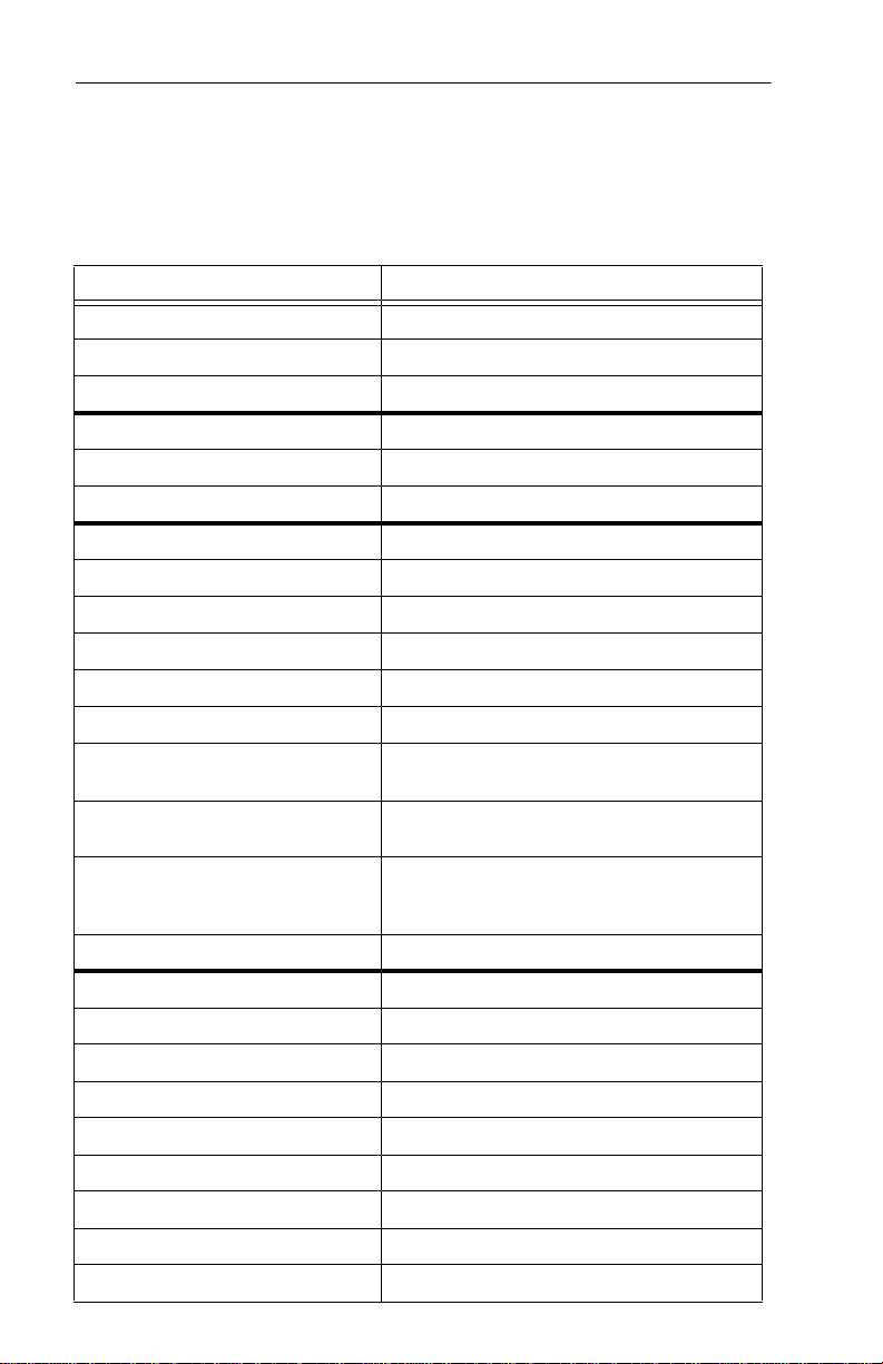
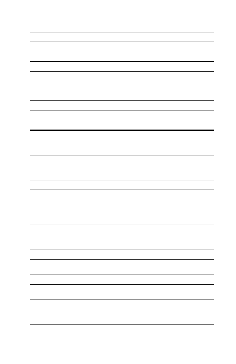
Specification summary table
The specifications listed in this table are for quick reference. For details
on specification measurement or definition, see the appropriate section
of this manual.
Drive Specification ST320014A
Formatted Gbytes (×106 bytes) 20
Guaranteed sectors 39,102,336
Bytes per sector 512
Default sectors per track 63
Default read/write heads 16
Default cylinders 16,383
Physical read/write heads 1
Discs 1
Recording density BPI (bits/inch max) 543,000
Track density TPI (tracks/inch) 58,000
Areal density (Mbits/inch2 max) 31,500
Spindle speed (RPM) 5,400
Internal data-transfer rate
(Mbits/sec max)
I/O data-transfer rate
(Mbytes/sec max)
ATA data-transfer modes
supported
Cache buffer (Mbytes) 2
Height (mm max) 19.99
Width (m m max) 101.9
Length (mm max) 147.0
Weight (typical) 455 grams (1.00 lb)
Average seek time (msec typical) 12.7
Track-to-track seek time (msec typical) 1.2 (read) 2.0 (write)
Read/write seek time (msec typical) 18.0 (read) 24.9 (write)
Full-stroke seek time (msec typical) 36.8 (read); 42.0(write)
Power-on to ready (sec max) 7 sec
Multiword DMA modes 0–2
Ultra DMA modes 0–5
445
100
PIO modes 0–4
Page 11
ST320014A Product Manual, Rev. D 3
Drive Specification ST320014A
Standby to ready (sec typical) 6.5 sec
Spindown (sec typical) 10 sec
Startup current (typical) 0.9 amps (5V), 1.9 amps (12V)
Seek power (typical) 6.0 watts
Read/Write power 5.5 watts
Idle mode (typical) 4.5 watts
Standby mode (typical) 1.2 watts
Sleep mode (typical) 1.0 watts
Voltage tolerance (including noise) 5V ± 5%, 12V ± 10%
Ambient temperature 0° to 60°C (op.), –40° to 70°C (nonop.)
Temperature gradient
(°C per hour max) 20°C
Relative humidity
(op. and nonop.)
Relative humidity gradient 30% per hour max
Wet bulb temperature (°C max) 29.4 (op.), 40.0 (nonop.)
Altitude, operating –60.96 m to 3,048 m (–200 ft to 10,000+ ft)
Altitude
(meters below mean sea level, max) –121.92 m to 12,192 m (–400 ft to 40,000+ ft)
Shock, operating (Gs max at 2 msec) 63 Gs
Shock, nonoperating
(Gs max at 1 and 2 msec) 350 Gs
Vibration, operating 0.5 Gs (0 to peak, 22–350 Hz)
Vibration, nonoperating 5 Gs (0 to peak, 22–350 Hz)
Drive acoustics
Sound power in bels
Nonrecoverable read errors 1 per 10
Mean time between
failures (power-on hours) 600,000
Contact start-stop cycles (25°C, 40%
relative humidity)
SeaShield No
5% to 90% (op.)
5% to 95% (nonop.)
Idle: 2.6 (typical), 2.8 (max)
Seek: 2.7 (typical), 2.9 (max)
13
bits read
50,000
Page 12
4 ST320014A Product Manual, Rev. D
1.0 Drive specifications
Unless otherw ise noted, all spe cifications a re measured unde r ambient
conditions, at 25°C, and nominal power. For convenience, the phrases
the drive and this dr ive are used throughout this manual to indicate the
ST320014A.
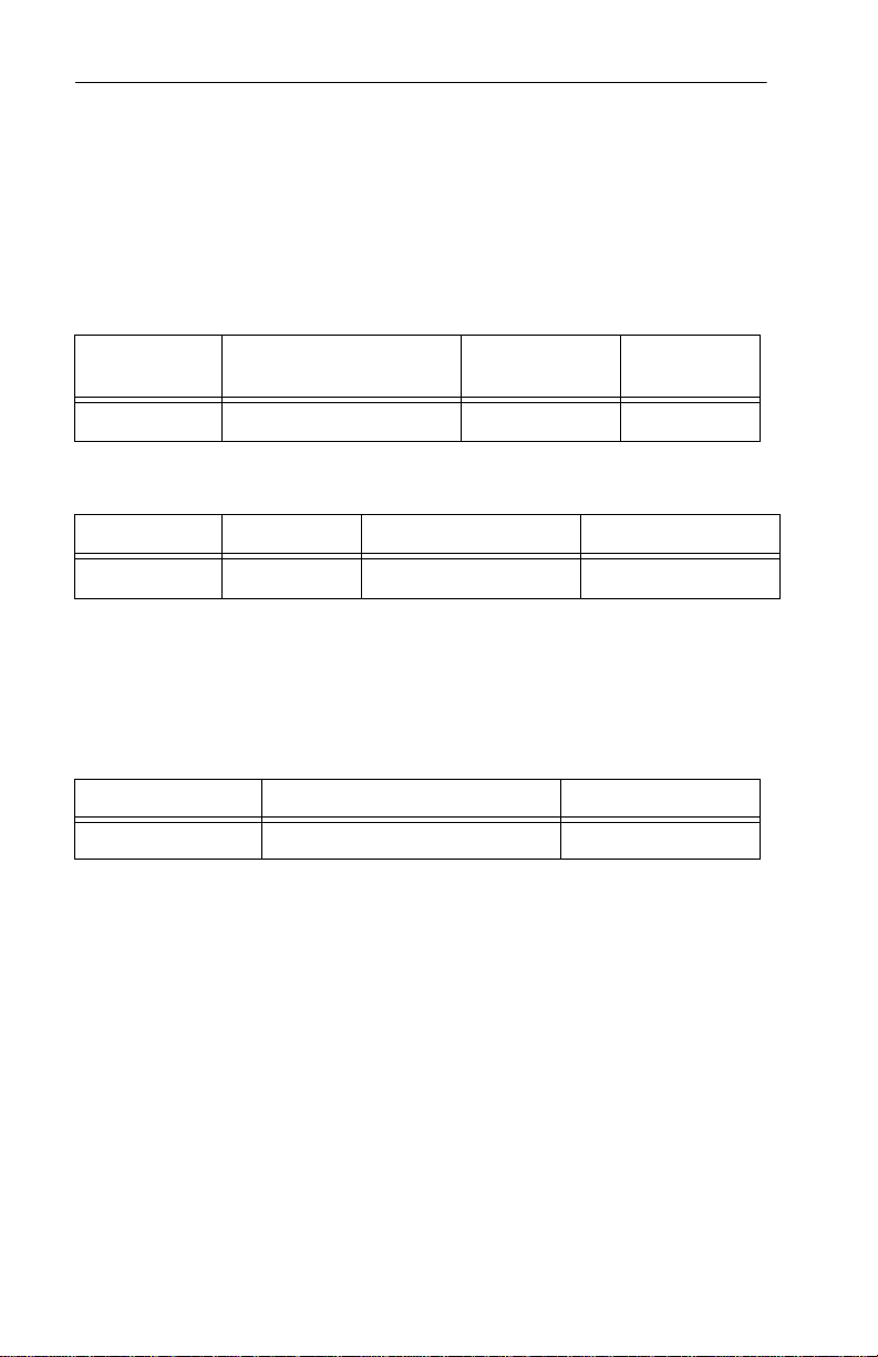
1.1 Formatted capacity
Drive Model Formatted Gbytes Guaranteed
sectors
ST320014A 20 39,102,336 512
Bytes per
sector
1.1.1 Default logical geometry
CHS Mode Cylinders Read/Write heads Sectors per track
ST320014A 16,383 16 63
LBA Mode
When addressin g d riv e i n L BA m ode, al l blo ck s ( se cto rs) a re c ons ec utively numbered from 0 to n–1, where n is the number of guaranteed
sectors as defined above.
1.2 Physical organization
Drive Model Read/Write heads (GMR) Number of discs
ST320014A 1 1
1.3 Recording and interface technology
Interface ATA
Recording method 96/102 GPRML
Recording density BPI (bits/inch) 543,000
Track density TPI (tracks/inch) 58,000
Areal density (Mbits/inch2 max) 31,500
Spindle speed (RPM) (± 0.2%) 5,400
Internal data-transfer rate
(Mbits/sec max)
I/O data-transfer rate
(Mbytes/sec max)
445
16.6 (PIO mode 4)
100 (Ultra DMA mode 5)
Page 13
ST320014A Product Manual, Rev. D 5
Interleave 1:1
Cache buffer (Mbytes) 2
1.4 Physical cha racteristics
Drive Specification ST320014A
Maximum height mm (inches) 19.99 (0.787)
Maximum width mm (inches) 101.9 (4.01)
Maximum length mm (inches) 147.0 (5.78)
Typical weight grams (pounds) 455 (1.00)
1.5 Start/stop times
Power-on to Ready (sec) 6.5 (typical)
Standby to Ready (sec) 6.5 (typical)
Ready to spindle stop (sec) 10 (typical)
1.6 Seek times
Average seek time (msec typical) 12.7
Track-to-track seek time (msec typical) 1.2 (read) 2.0 (write)
Read/write seek time (msec typical) 18.0 (read) 24.9 (write)
Full-stroke seek time (msec typical) 36.8 (read); 42.0(write)
Power-on to ready (sec max) 7 sec
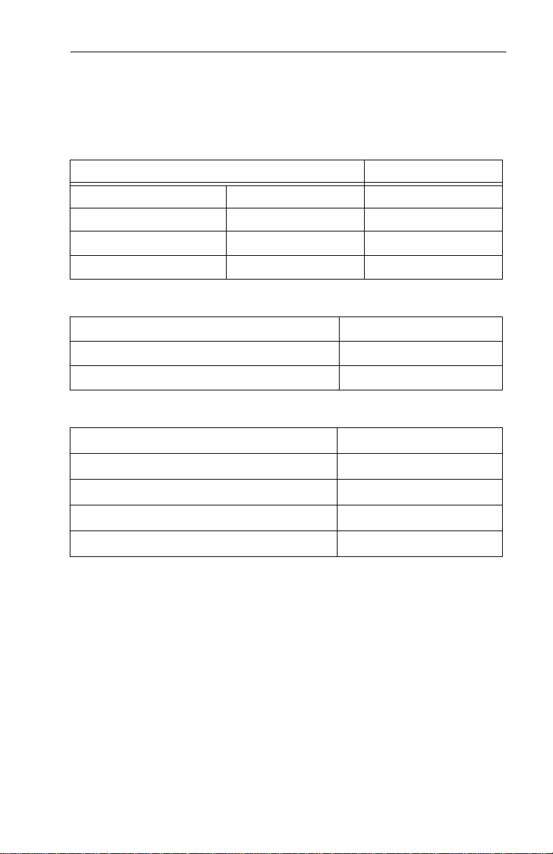
Seek measurements are taken with nominal power at 25°C ambient
temperature. All times are measured using drive diagnostics. Seek time
specifications are defined as follows:
• Track-to-track seek time is an average of all possible single-track
seeks in both directions.
• Average seek time is a true statistical random average of at least 5,000
measurements of seeks between random tracks, less overhead.
• Full-stroke seek time is one-half the time needed to seek from the first
data cylinder to the m ax imu m d ata cy l inder an d b ac k t o th e fir st dat a
cylinder. The full-stro ke t ypic al v alue is dete rm in ed by ave ragi ng 10 0
full-stroke seeks in both directi on s.
Note. These drives are designed to meet the seek times represente d
in this manual consis tently. Phys ical seeks, r egardless of mode
Page 14

6 ST320014A Product Manual, Rev. D
(such as track-to-track and average), are expected to meet or
exceed the noted values. How ever, due to the man ner in which
these drives are formatted, benchmark tests that include com
mand overhead or meas ure logical seeks may pr oduce results
that vary from these specifications.
1.7 Power specifications
The drive receives DC power (+5V or +12V) through a four-pin standard
drive power connector.
1.7.1 Power consumption
Power requirements f or the drives are listed in the table on page 9.
Typical power measurements are based on an average of drives tested,
under nominal conditions, using 5.0V input voltage at 25°C ambient
temperature.
• Spinup power
Spinup power is measured from the time of power-on to the time that
the drive spindle reaches operating speed.
• Seek Mode
The read/write actuator arm moves in a random seek mode, with 80%
of the time spent seeking rand omly among all the logic al bloc ks, and
20% of the time idle. The current is measured over a 10-second period.
No data is read or written during this test.
-
• Read/Write power and current
Read/write power is me asured with the heads on track, ba sed on a
16-sector write followed by a 32-msec delay, then a 16-sector read
followed by a 32-msec delay.
• Operating power and current
The read/write actuator arm moves in a random read/write mode, with
80% of the time spent seeking, reading, and writing randomly among
all the logical blocks, and 20% of the time idle. The current is measured
over a 10-second period.
• Idle mode power
Idle mode power is measur ed with the driv e up to speed, with s ervo
electronics active and with the heads in a random track location.
• Standby mode
During Standby mode , the driv e accep ts comma nds, but the drive is
not spinning, and t he servo and read/write electr onics are in p owerdown mode.
Page 15
ST320014A Product Manual, Rev. D 7
-
C
Typical Amps (Mean)
Power Mode Typical
Watts
Spinup — 0.90 1.90
Seek (Random,
no read/write) 6.0 0.672 0.220
5V 12V
Operating (read/
write)
Idle 4.5 0.468 0.180
Standby 1.2 0.192 0.020
Sleep 1.0 0.157 0.018
5.5 0.572 0.220
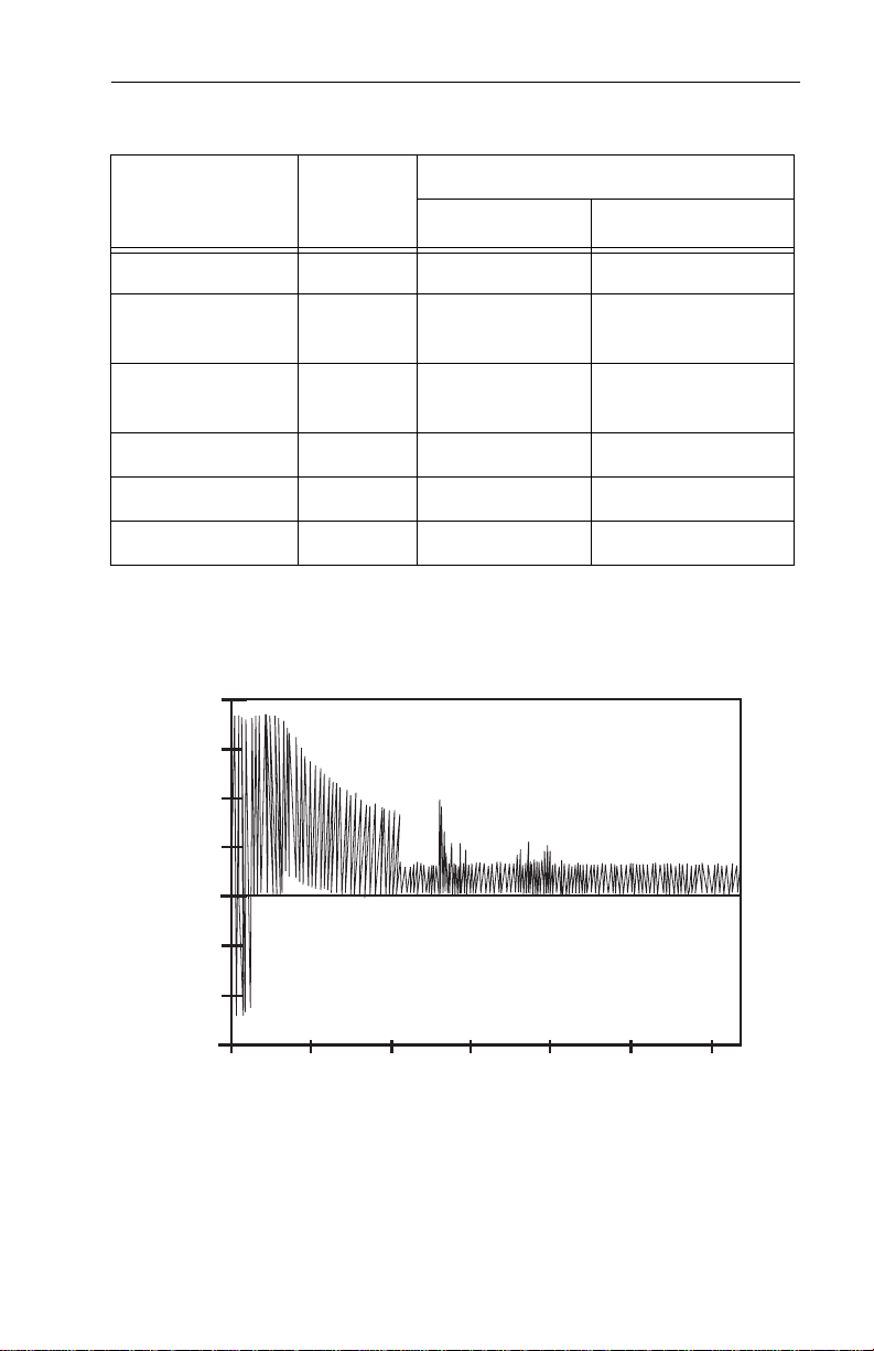
1.7.1.1 Typical current profile
urrent (amps)
2.0
1.0
0.0
1.0
123456
Time (seconds)
Figure 1. Typical startup and operation current profile
Page 16
8 ST320014A Product Manual, Rev. D
1.7.2 Conducted noise
Input noise ripple i s mea su red a t the ho st sy s tem powe r su ppl y ac ross
an equivalent 80-ohm resistive load on the +12 volt line or an equivalent
15-ohm resistive load on the +5 volt line.
• Using 12-volt power, the drive is expected to operate with a maximum
of 120 mV peak-to-peak square-wave injected noise at up to 10 MHz.
• Using 5-volt power, th e dr ive is ex pected to op er ate with a ma xi mum
of 100 mV peak-to-peak square-wave injected noise at up to 10 MHz.
Note. Equivalent resis tance is calcu lated by di viding the nomina l volt-
age by the typical RMS read/write current.
1.7.3 Voltage tolerance
Voltage tolerance (including noise): 5V ± 5% and 12V ± 10%
1.7.4 Power-management modes
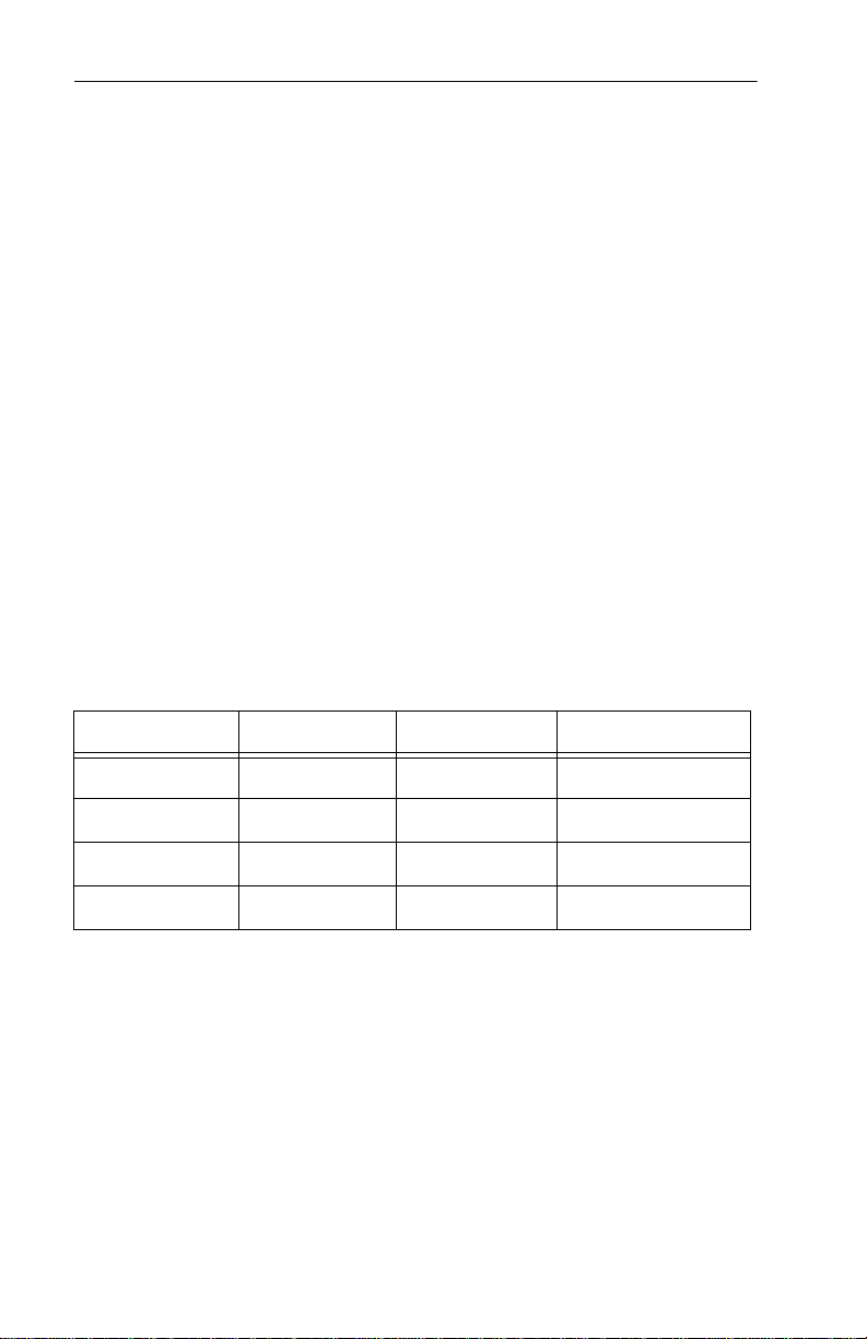
The drive provides programmable power management to provide greater energy efficiency . In m ost sys tems, you can contr ol po wer mana gement through the system setup program. The drive features the following
power-management modes:
Power Modes Heads Spindle Buffer
Active Tracking Rotating Enabled
Idle Tracking Rotating Enabled
Standby Parked Stopped Enabled
Sleep Parked Stopped Disabled
• Active mode
The drive is in Active mode during the read/write and seek operations.
• Idle mode
The buffer remains enabled, and the drive accepts all commands and
returns to Active mode any time disc access is necessary.
• Standby mode
The drive enters Standby mode when the host sends a Standby
Immediate command. If the hos t has set the sta ndb y timer, the drive
can also enter Standby mo de automatical ly after the driv e has been
inactive for a specifia ble length of time. The standby ti mer delay is
Page 17

ST320014A Product Manual, Rev. D 9
established using a Standby or Idle command. In Standby mode, the
drive buffer is enabled, the heads are parked and the spindle is at rest.
The drive accepts all commands and returns to Active mode any time
disc access is nece ssary.
• Sleep mode
The drive enters Sleep mode after rece iving a Slee p command from
the host.
parked and the spindle is at res t. The drive l eaves Sleep mode a fter
it receives a Hard Reset or Soft Reset from the host. After receiving a
reset, the drive exits Sleep mo de and enters Standby mode with all
current translation parameters intact.
In Sleep mode, the drive buf fer is disabled, the heads are
• Idle and Standby timers
Each time the drive performs an Active function (read, write or seek),
the standby timer is reinitia lized and begins counting down from its
specified delay times to zero. If the standby timer reaches zero before
any drive activity is require d, the dr ive make s a tran siti on to Stan dby
mode. In both Idle and Standby mode, the drive accepts all commands
and returns to Active mode when disc access is necessary.
1.8 Environmental tolerances
1.8.1 Ambient temperature
Ambient temperature i s defined as the temper a tur e o f t he env ir on men t
immediately surrounding the drive. Actual drive case temperature should
not exceed
ommended measurement locations are shown in Figure 4 on page 20.
Above 1,000 feet (305 m eters), the maximum temper ature is derated
linearly to 112°F (44°C) at 10,000 feet (3,048 meters).
Operating 0° to 60°C (32° to 131°F)
Nonoperating –40° to 70°C (–40° to 158°F)
65°C (149°F) within the operating ambient conditions. Rec-
1.8.2 Temperature gradient
Operating/Nonoperating 20°C per hour (36°F per hour) max,
without condensation
Page 18

10 ST320014A Product Manual, Rev. D
1.8.3 Humidity
1.8.3.1 Relative Humidity
Operating 5% to 90% noncondensing (30% per hour max)
Nonoperating 5% to 95% noncondensing (30% per hour max)
1.8.3.2 Wet bulb temperature
Operating 29.4°C (84°F) max
Nonoperating 40.0°C (104°F) max
1.8.4 Altitude
Operating –60.96 m to 3,048 m (–200 ft to 10,000+ ft)
Nonoperating –121.92 m to 12,192 m (–400 ft to 40,000+ ft)
1.8.5 Shock
All shock specifications assume that the drive is mounted securely with
the input shock appli ed at the drive mounting screws. Sh ock may be
applied in the X, Y or Z axis.
1.8.5.1 Operating shoc k
These drives comply with the performance levels specified in this document when subjected to a maximum op erating shock of 63 Gs (ba sed
on half-sine shock p ulses of 2 msec). Sh ocks should not be repe ated
more than two times per second.
1.8.5.2 Nonoperating shock
The nonoperating shock level that the drive can experience without
incurring physical damage or degradation in performance when subse
quently put into operation is 350 Gs (based on nonrepetitive half-sin e
shock pulses of 1 and 2 msec duration).
1.8.6 Vibration
All vibration speci fications assume that the drive is mounted securely
with the input vibration app lied at the dr ive mounting s crews. Vib ration
may be applied in the X, Y or Z axis.
-
Page 19

ST320014A Product Manual, Rev. D 11
1.8.6.1 Operati ng vibration
The following table lists the maximum vibration levels that the drive may
experience while meeting the performance standa rds specified in this
document.
5–21 Hz 0.02-inch displacement (peak to peak)
22–350 Hz 0.5 Gs acceleration (zero to peak)
351–500 Hz 0.25 Gs acceleration (zero to peak)
1.8.6.2 Nonoperating vibration
The following table lis ts the maximum nonoperatin g vibration that the
drive may experience without incurring physical damage or degradation
in performance when subsequently put into operation.
5–21 Hz 0.2-inch displacement (peak to peak)
22–350 Hz 5.0 Gs acceleration (zero to peak)
351–500 Hz 1.0 Gs acceleration (zero to peak)
1.9 Drive acoustics
Drive acoustics are measured as overall A-weighted acoustic sound
power levels (no pure tones). All measurements are generally consistent
with ISO document 7779. Sound power measurements were taken
under essentially free-field conditions over a reflecting plane. For all
tests, the drive was oriented with the cover facing upward.
Note. For seek mode tests, the drive was placed in seek mode only.
The number of seeks per second is defined by the following
equation:
Number of seeks per second = 0.4 / (average latency + average access time)
ST320014A
Acoustic mode Idle Seek
Sound power (bels) 2.6 (typ)
2.7 (typ)
2.8 (max)
2.9 (max)
Page 20

12 ST320014A Product Manual, Rev. D
1.10 Electromagnetic immunity
When properly installed in a representative host system, the drive
operates without errors or degra dation in performanc e when sub jected
to the radio frequency (RF) environments defined in the following table:
Test Description Performance
Electrostatic
discharge
Radiated RF
immunity
Electrical fast
transient
Surge
immunity
Conducted
RF
immunity
Voltage dips,
interrupts
Contact, HCP , VCP: ± 4 kV; Air:
± 8 kV
80 to 1,000 MHz, 3 V/m,
80% AM with 1 kHz sine
900 MHz, 3 V/m, 50% pulse
modulation @ 200 Hz
± 1 kV on AC mains, ± 0.5 kV
on external I/O
± 1 kV differential, ± 2 kV com-
mon, AC mains
150 kHz to 80 MHz, 3 Vrms,
80% AM with 1 kHz sine
0% open, 5 seconds
0% short, 5 seconds
40%, 0.10 seconds
70%, 0.01 seconds
Level
B EN 61000-4-2: 95
A EN 61000-4-3: 96
B EN 61000-4-4: 95
B EN 61000-4-5: 95
A EN 61000-4-6: 97
C
C
C
B
Reference
Standard
ENV 50204: 95
EN 61000-4-11: 94
1.11 Reliability
Nonrecoverable read errors 1 per 1013 bits read, max
Mean time between failures 600,000 power-on hours (nominal
power, 25°C ambient temperature)
Contact start-stop cycles
50,000 cycles (at nominal voltage
and temperature, with 60 cycles per
hour and a 50% duty cycle)
Preventive maintenance None required
Page 21

ST320014A Product Manual, Rev. D 13
1.12 Agency certification
1.12.1 Safety certification
The drive is recognized in acc ordance with UL 1950 and CSA C22.2
(950) and meets all applica ble sections of IEC950 and EN 60950 as
tested by TUV North America.
1.12.2 Electromagnetic compatibility
Hard drives that display the CE ma rk comply wit h the Europea n Union
(EU) requirements specified in the Electromagnetic Compatibility Direc
tive (89/336/EEC). Testin g is performed to the levels specified by the
product standard s for Information Technology Equ ipment (ITE). E mis
sion levels are defined b y EN 55022, Clas s B and the immu nity levels
are defined by EN 55024.
Seagate® uses an independent laborat ory to confirm compliance wit h
the EC directives specified in the previous paragraph. Drives are tested
in representative end-user systems. Although CE-marked Seagate
drives comply with the d irectives when used in the test systems, we
cannot guarantee tha t all systems will comp ly with the directive s. The
drive is designed for operation inside a properly designed enclosure, with
properly shielded I/O cable (if necessary) and terminators on all unused
I/O ports. Computer manufacturers and system integrators should con
firm EMC compliance and provide CE marking for their products.
-
-
-
Korean RRL
If this drive has the Korea Ministr y of Information and Communica tion
(MIC) logo, it complies with paragraph 1 of Article 11 of the Electromag
netic Compatibility c ontrol Regulation and meets the Electromagnetic
Compatibility (EMC) Framework requirements of th e Radio Research
Laboratory (RRL) Minis try o f In for mat ion an d Co mmu nic at ion Rep ubl ic
of Korea.
This drive has been tested and complies with the Electromagnetic
Interference/Electromagnetic Susceptibility (EMI/EMS) for Class B prod
ucts. Drives are tested in a representative, end-user system by a Koreanrecognized lab.
-
-
• EUT name (model numbers): ST320014A
• Certificate numbers: E-H011-02-1589 (B)
• Trade name or applicant: Seagate Technology
• Manufacturing date: June 2002
• Manufacturer/nationality: Singapore
Page 22

14 ST320014A Product Manual, Rev. D
Australian C-Tick (N176)
If this drive has the C-Tick marking, it complies with the Australia/New
Zealand Standard AS/NZS 3548 1995 and meets the Electroma gnetic
Compatibility (EMC) Framework requirements of the Australian Commu
nication Authority (ACA).
Taiwan BSMI
If this drive has the symbol of an ar row inside a circle with a six-digi t
identifier (D33027) below it, the drive complies with the Chinese National
Standard (CNS) 13438 and meets the Electromagnetic Compatibility
(EMC) Framework requirements of the Taiwanese Bureau of Standards,
Metrology and Inspection (BSM I) .
1.12.3 FCC verification
These drives are intended to be contained solely within a personal computer or similar enclosure (not attached as an exter nal device). As su ch,
each drive is considered to be a subassembly even when it is individually
marketed to the customer. As a subassembly, no Federal Communications
Commission verification or certification of the device is required.
Seagate Technol ogy LLC has tested this device in enclosur es as described above to ensure tha t the total assembly (e nclosu re, disc drive ,
motherboard, power supply, etc.) does comply with the limits for a Class
B computing devi ce, pursuant to S ubpart
Operation with noncertifie d assem blies is likely to resu lt in interf erenc e
to radio an d television reception.
J, Part 15 of the FCC rul es.
-
Radio and television interference. This equipment generates and
uses radio frequency energy and if not installed and used in strict
accordance with the manufacturer’s instructions, may cause interfer
ence to radio and television reception.
This equipment is des igned to provide reasonable protection agai nst
such interference in a residential installation. However, there is no
guarantee that interfer ence will not occur in a particu lar installation. If
this equipment does cause interference to radio or television, which can
be determined by turning the equipment on and off, you are encouraged
to try one or more of the following corrective measures:
-
• Reorient the receiving antenna.
• Move the device to one side or the other of the radio or TV.
• Move the device farther away from the radio or TV.
• Plug the computer into a different outlet so that the receiver and
computer are on different branch outlets.
Page 23

ST320014A Product Manual, Rev. D 15
If necessary, you s hould consult your deale r or an experienced ra dio/
television technician for additional suggestions. You may find helpful the
following booklet prepared by the Federal Communicatio ns Commis
sion: How to Identify and Resolve Radio-Televisio n Interference Prob-
lems. This booklet is availab le from the Superinte ndent of Docume nts,
Government Printing Office, Washington, DC 20402. Refer to pub-
U.S.
lication number 004-000-00345-4.
-
Page 24

16 ST320014A Product Manual, Rev. D
2.0 Configuring and mounting the drive
This section conta in s th e s pec if ic ati ons and instruction s for c on figuring
and mounting the drive.
2.1 Handling and static-discharge precautions
After unpacking, and before installation, the drive may be exposed to
potential handling and electrostatic discharge (ESD) hazards. Observe the
following standard handling and static-discharge precautions:
Caution:
• The SeaShell™ replaces electrostatic discharge (ESD) bags. The
SeaShell package is a shock-ribbed, transparent clamshell enclosure
that limits a drive’s exposure to ESD and also protects against external
shocks and str esses. Th e design pe rmits atta ching cab les, softwar e
loading and label/barc ode scanning with out removing the dri ve from
the SeaShell. This minimizes handling damage. Keep the drive in the
SeaShell package until you are ready to install it.
• Before handling the drive, put on a grounde d wrist strap, or ground
yourself frequentl y by touching the metal chas sis of a com puter that
is plugged into a grounded outlet. Wear a grounded wrist strap
throughout the entire installation procedure.
• Handle the drive by its edges or frame only.
• The drive is extremely fragile—handle it with care. Do not press down
on the drive top cover.
• Always rest the drive on a padded, anti static surfac e until y ou moun t
it in the computer.
• Do not touch the connector pins or the printed circuit board.
• Do not remove the factory-installed labels from the drive or cover them
with additional labels. Removal voids the warranty. Some factoryinstalled labels contain information needed to service the drive. Other
labels are used to seal out dirt and contamination.
Page 25
ST320014A Product Manual, Rev. D 17
2.2 Breather filter hole precautions
This section contains information regarding the precautions which
should be taken regarding the breather filte r hole in Seagate har d disc
drives. Proper p recautions should be taken to ens ure full function ality
and prevent possible damage to the drive.
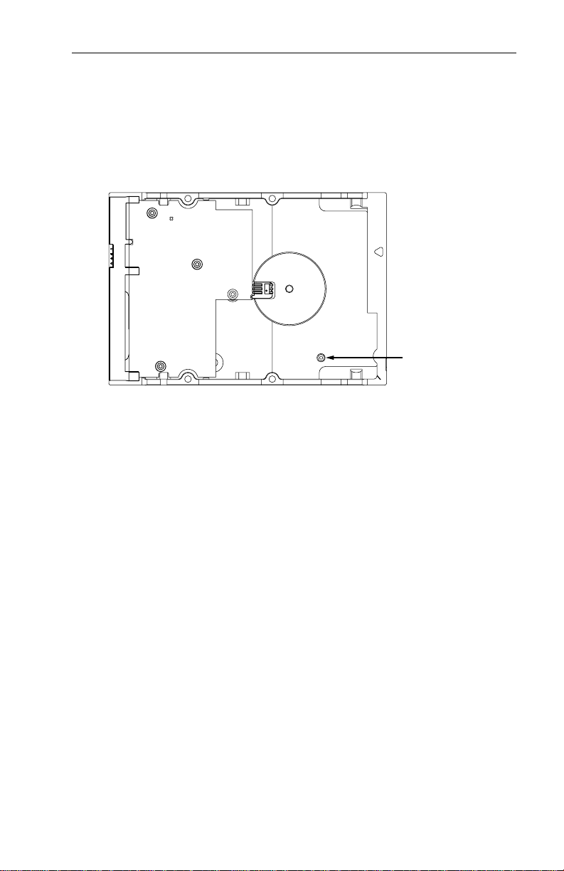
Breather Hole
Do not cover
or seal.
Figure 2. Breather filter hole location
Caution: Do not cover, seal, or insert any object into this hole.
This hole has two purposes:
• To allow condensation inside the hard disc to escape
• To allow air pressure inside the hard disc to equalize with ambient
pressure
If this hole is cov ered, sealed, or penetrated by any object, the drive
reliability may be compromised and could lead to permanent damage—
doing so voids the warranty.
Page 26
18 ST320014A Product Manual, Rev. D
2.3 Jumper settings
2.3.1 Master/slave configuration
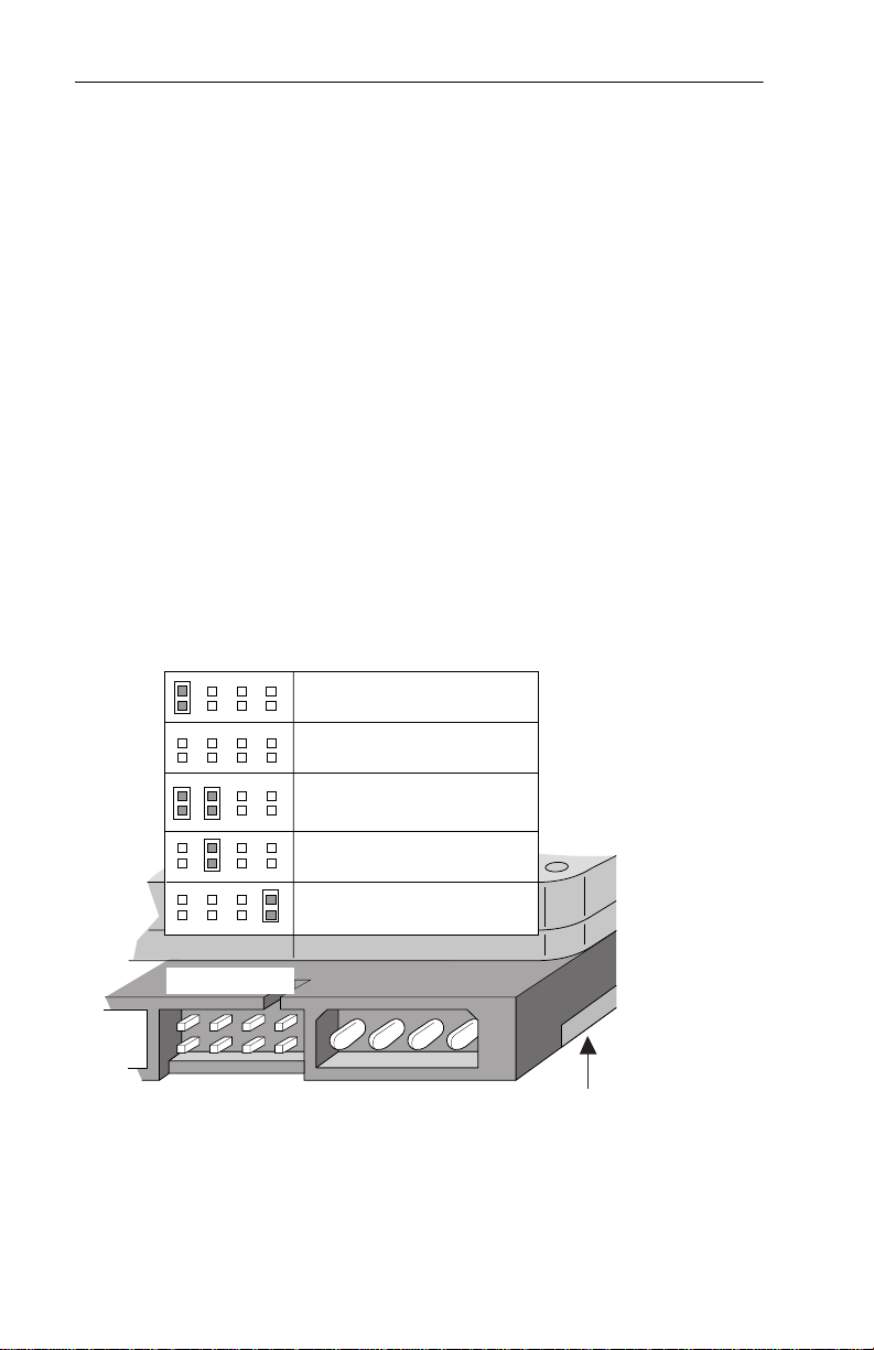
The options jumper block shown in Figure 2 is used to configure the drive
for operation. It is the 8-pin dual header between the interface connector
and the power connecto r. Use the following settings to c onfigure the
drive as a master or a slave.
Master or single drive. The drive is configured at the factory for a master
or single-drive operation with a jumper set on pins 7 and 8.
Drive as slave. Remove all jumpers.
Drive as master with a non-ATA-compatible slave.
Set a jumper on pins 5 and 6 a nd a jumper o n pins 7 and 8. Use this
jumper s etting only if the drive does not work as a master with no jumpers
installed.
Options jumper block
Master or single drive
Drive is slave
Master with non ATAcompatible slave
Cable select
Limit drive capacity
1753
684
Figure 3. Master/slave jumper settings
2
Circuit Board
Page 27

ST320014A Product Manual, Rev. D 19
2.3.2 Cable-select option
Computers that use cable-select determine the master and slave drives
by selecting or dese lecting p in 28, CSEL, on th e interfac e bus. Mas ter
and slave drives are determined by their physical position on the cable.
To enable cable select, set a jumper on pins 5 and 6 as shown in
3 on page 18. Refer to your computer manual to determine whether your
computer supports this option.
Figure
2.3.3 Ultra ATA/100 cable
An 80-conductor 40-pin cable is required to run Ultra DMA mode 3, mode
4 and mode 5. This cabl e uses even -numbered c onductors connected
to the ground pins to improve signal integrity.
Notes:
1. The drive supports both host and drive cable detection. The host
detects the 80-conductor cable by sampling pin 34, CBLID–, on
the interface bus. The drive detects the 80-cond uctor cable by
sensing a capacitor at the host side through the CBLID– signal.
The result is reported in a Fast Rise Detected bit (bit 13 of word
93 in the Identify drive parameter block).
2. When using a 4 0-pin 80 -conductor cable, att ach th e blue con-
nector to the motherboard, the black connector to the master
drive, and the grey connector to the slave.
Page 28
20 ST320014A Product Manual, Rev. D
th
2.1 Drive mounting
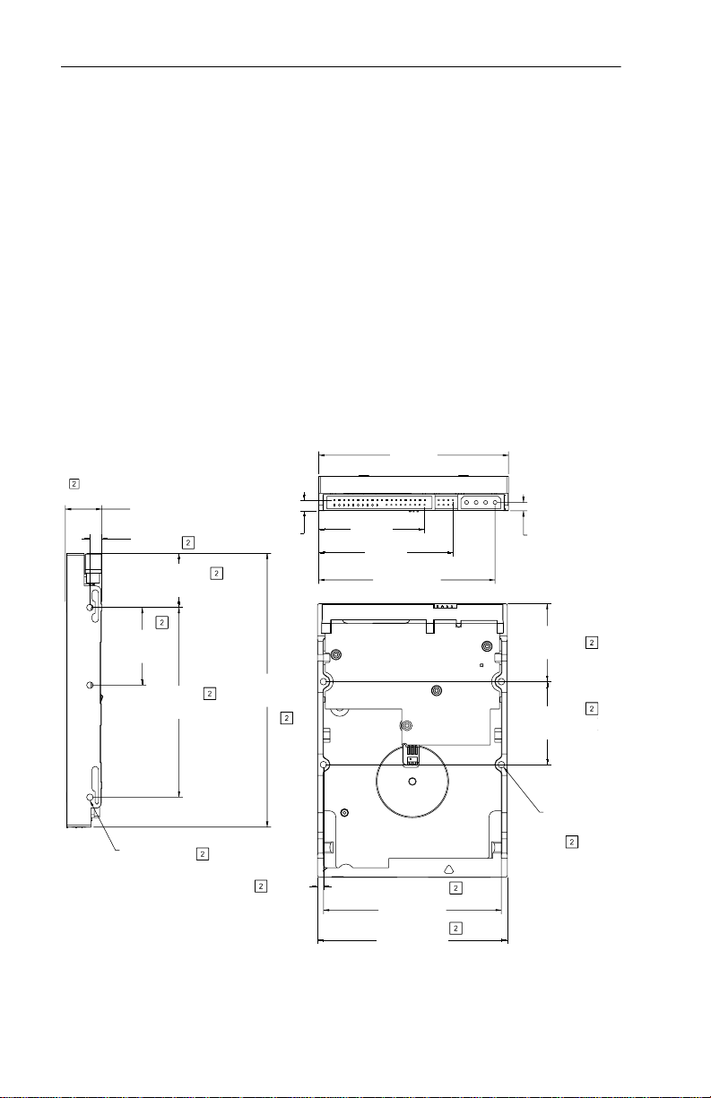
You can mount the drive in any orientation using four screws in the sidemounting holes or four screws in the bottom-mounting holes. See Figure
3 for drive mounting dimensions. Follow these important mounting
precautions when mounting the drive:
• Allow a minimum clearanc e of 0.030 inches (0.76 mm) around the
entire perimeter of the drive for cooling.
• Use only 6-32 UNC mounting screws. Insert the screws no more than
0.20 inch (5.08 mm) into the bottom mounting holes and no more than
0.14 inch (3.55 mm) into the side mounting holes.
• Do not overtighten the mounting screws (maximum torque: 6 inch-lb).
• Do not use a drive interface cable that is more than 18 inches long.
4.000 in.
2.229 in.
(56.616 mm)
2.829 in.
(71.856 mm)
3.717 ± 0.30 in.
(94.406 ± 0.762 mm)
(101.600 mm)
0.176 ± 0.015 in.
(4.480 ± 0.381 mm)
Notes:
1. Dimensions are shown in inches (mm)
Dimensions are per SFF-8301 specification
0.787 in. max
(19.99 mm)
0.250 in. max
(6.350 mm)
+0.024
1.140 in.
–0.015
+0.635
(28.956 mm)
–0.381
0.226 in.
(5.750 mm)
+0.025
1.683 in.
–0.015
+0.635
(41.605 mm)
–0.381
+0.015
5.770 in.
+0.025
4.000 in.
–0.015
+0.635
(101.60 mm)
–0.381
3X 6-32 UNC-2B
max. insertion depth
0.14 in. both sides
–0.005
+0.38
(146.56 mm)
–0.13
0.125 in.
(3.175 mm)
3.750 ± 0.10 in.
(95.250 ± 0.254 mm)
+0.015
4.000 in.
–0.005
+0.381
(101.60 mm)
–0.127
Figure 4. Mounting dimensions—top, side and end view
+0.020
2X 1.645 in.
–0.010
+0.508
(41.783 mm)
–0.254
+0.020
2X 1.750 in.
–0.010
+0.508
(44.450 mm)
–0.254
4X 6-32 UNC-2B
max. insertion dep
0.22 in.
Page 29

ST320014A Product Manual, Rev. D 21
3.0 ATA interface
These drives use the industry-standard ATA task file interface that
supports 16-bit data transfers. It supports ATA programmed input/output
(PIO) modes 0–4; multiwor d DMA modes 0–2, and Ultr a DMA modes
0–5. The drive also s upports the use of the IORDY sig nal to provide
reliable high-speed data transfers.
You can use a daisy-chain ca ble to connect two drives to a single AT
host bus. For detailed i nform ation abou t the AT A int erface, r efer to th e
draft of AT Attachment with Packet Interface Extension (ATA/ATAPI-Rev
6), NCITS T13 1153D, subsequently referred to as the Draft ATA-Rev 6
Standard.
3.1 ATA interface signals and connector pins
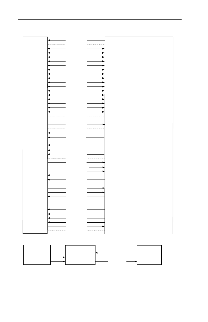
Figure 5 on page 22 summarizes the signals on the ATA interface
connector that the drive supports. For a detailed description of these
signals, refer to the Draft ATA-Rev 6 Standard.
Page 30
22 ST320014A Product Manual, Rev. D
.
Drive pin #
10
11
12
13
14
15
16
17
18
19
20
21
22
23
24
25
26
27
28
29
30
31
32
33
34
35
36
37
38
39
40
Signal name
–
1
2
3
4
5
6
7
8
9
Reset
Ground
DD7
DD8
DD6
DD9
DD5
DD10
DD4
DD11
DD3
DD12
DD2
DD13
DD1
DD14
DD0
DD15
Ground
(removed)
DMARQ
Ground
DIOW–
STOP
Ground
DIOR
–
HDMARDY
HSTROBE
Ground
IORDY
DDMARDY–
DSTROBE
CSEL
–
DMACK
Ground
INTRQ
–
IOCS16
DA1
–
PDIAG
CBLID–
DA0
DA2
–
CS0
–
CS1
–
DASP
Ground
–
Host pin # and signal description
1
Hardware Reset
2
Ground
3
Host Data Bus Bit 7
4
Host Data Bus Bit 8
5
Host Data Bus Bit 6
6
Host Data Bus Bit 9
7
Host Data Bus Bit 5
8
Host Data Bus Bit 10
9
Host Data Bus Bit 4
10
Host Data Bus Bit 11
11
Host Data Bus Bit 3
12
Host Data Bus Bit 12
13
Host Data Bus Bit 2
14
Host Data Bus Bit 13
15
Host Data Bus Bit 1
16
Host Data Bus Bit 14
17
Host Data Bus Bit 0
18
Device Data (15:0)
19
Ground
(No Pin)
20
21
DMA Request
22
Ground
23
Device I/O Write:
Stop Ultra DMA Burst
24
Ground
25
Device I/O Read:
Host Ultra DMA Ready:
Host Ultra DMA Data Strobe
26
Ground
27
I/O Channel Ready
Device Ultra DMA Ready
Device Ulta DMA Data Strobe
28
Cable Select
29
DMA Acknowledge
30
Ground
31
Device Interrupt
32
Reserved
33
Host Address Bus Bit 1
34
Passed Diagnostics
Cable Assembly Type Identifier
35
Device Address (2:0)
36
Device Address (2:0)
37
Chip Select (1:0)
38
Chip Select (1:0)
39
Drive Active/Slave Present
40
Ground
Pins 28, 34 and 39 are used for master-slave communication (details shown below)
28
34
39
Drive 0 (master)Drive 1 (slave)
28
34
39
CSEL
PDIAG
DASP–
–
Host
28
34
39
Figure 5. I/O pins and supported ATA signals
Page 31
ST320014A Product Manual, Rev. D 23
3.1.1 Supported ATA commands
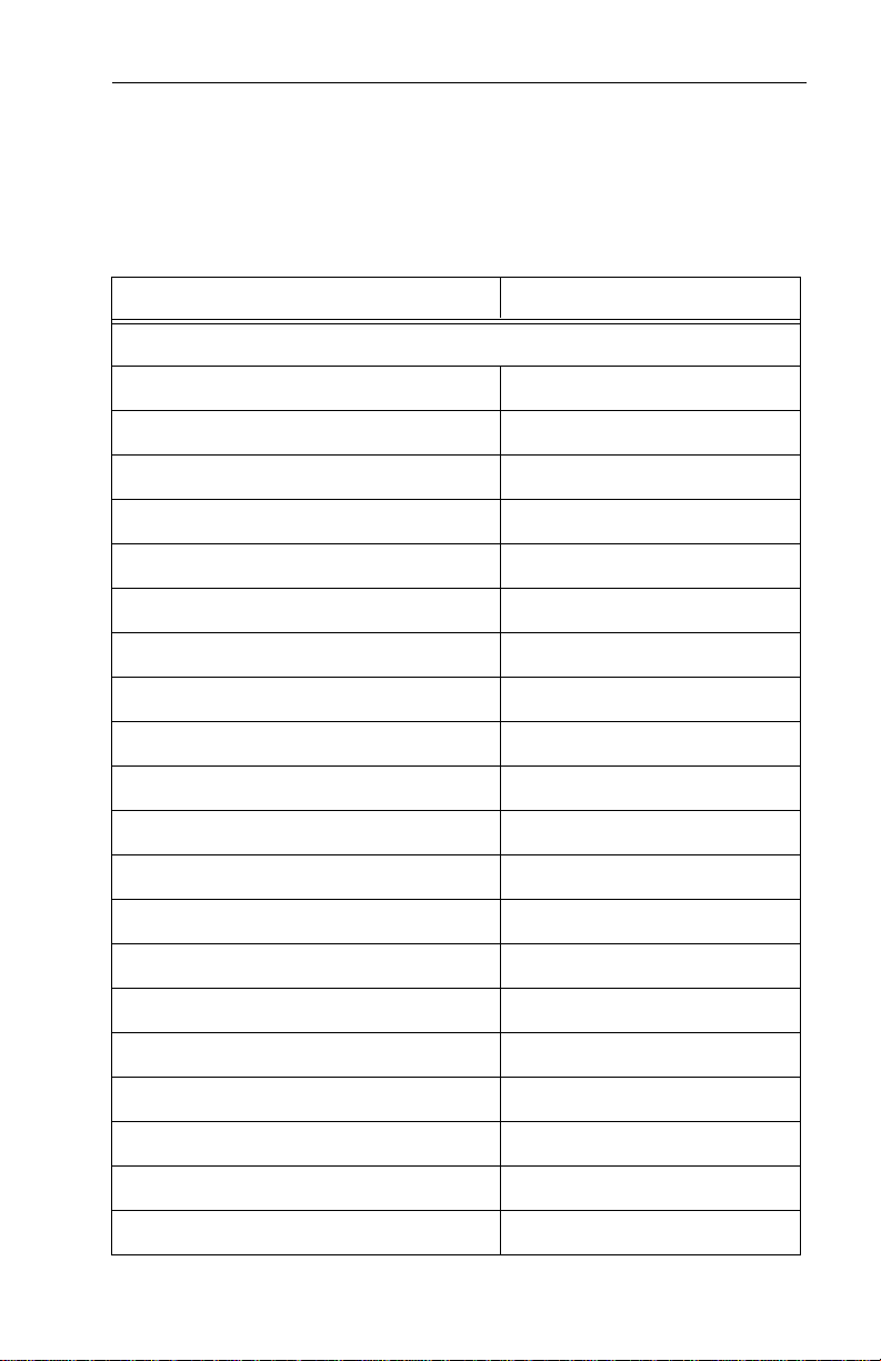
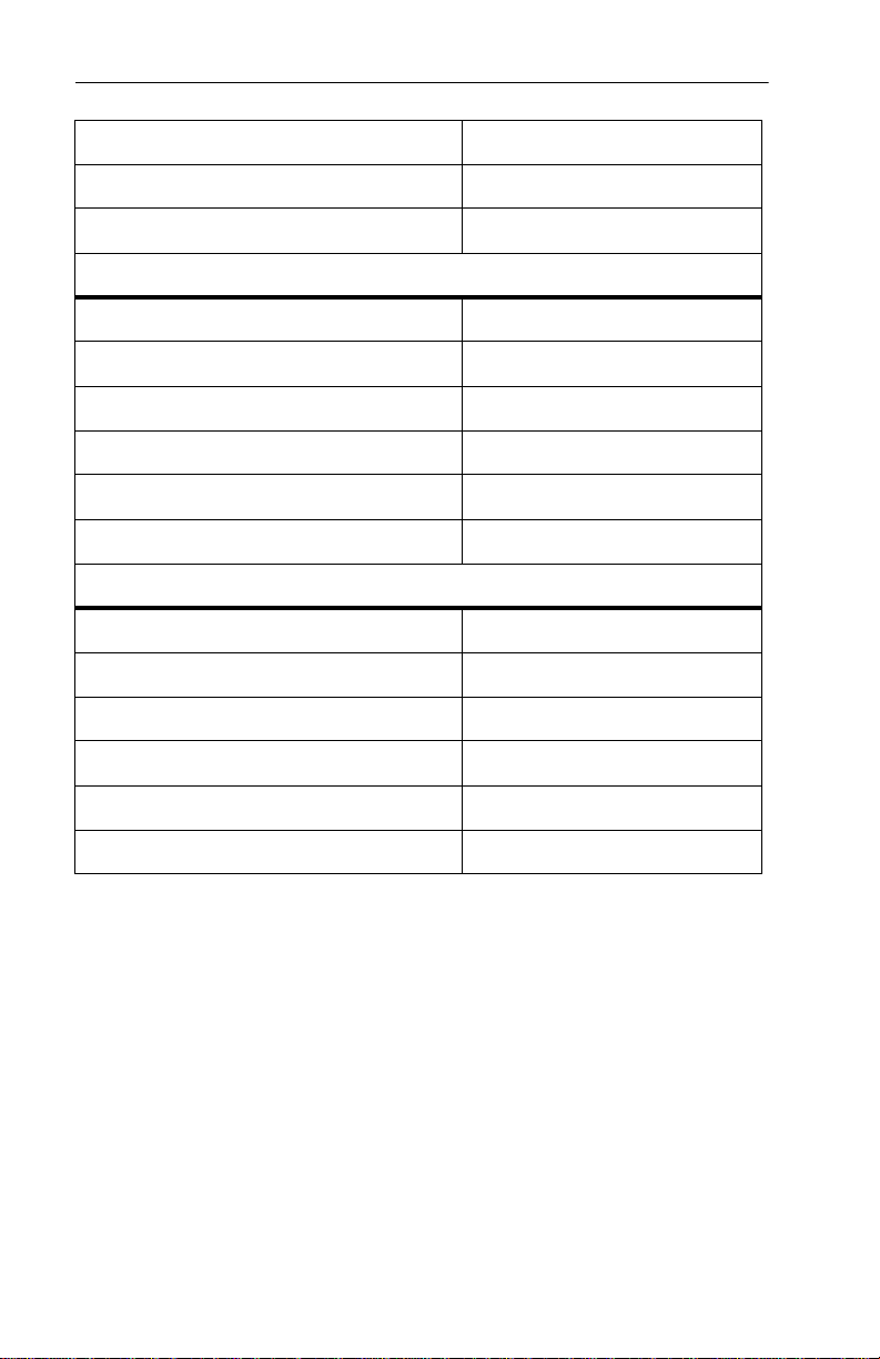
The following table lis ts ATA-standard commands that the dr ive supports. For a detailed description of the ATA commands, refer to the Draft
ATA-Rev 6 Standard.
subcommands used in the S.M.A.R.T. implementation.
Command name Command code (in hex)
See Section 3.1.4 on page 31 for details and
ATA-standard commands
Download Microcode 92
Execute Device Diagnostics 90
Flush Cache E7
Format Track 50
Identify Device EC
Initialize Device Parameters 91
Read Buffer E4
Read DMA C8
H, C9H
Read Multiple C4
Read Sectors 20
Read Verify Sectors 40
H, 21H
H, 41H
Read Native Max Address F8
Recalibrate 10
Seek 70
Set Features EF
H
H
H
H
H
H
H
H
H
H
H
H
Set Multiple Mode C6
Set Max Address F9
S.M.A.R.T. B0
Write Buffer E8
Write DMA CA
H
H
H
H
H, CBH
Page 32
24 ST320014A Product Manual, Rev. D
Command name Command code (in hex)
Write Multiple C5
Write Sectors 30
H
H, 31H
ATA-standard power-management commands
Check Power Mode 98H or E5
Idle 97H or E3
Idle Immediate 95H or E1
Sleep 99H or E6
Standby 96H or E2
Standby Immediate 94H or E0
ATA-standard security commands
Security Set Password F1
Security Unlock F2
Security Erase Prepare F3
Security Erase Unit F4
Security Freeze Lock F5
H
H
H
H
H
H
H
H
H
H
H
Security Disable Password F6
H
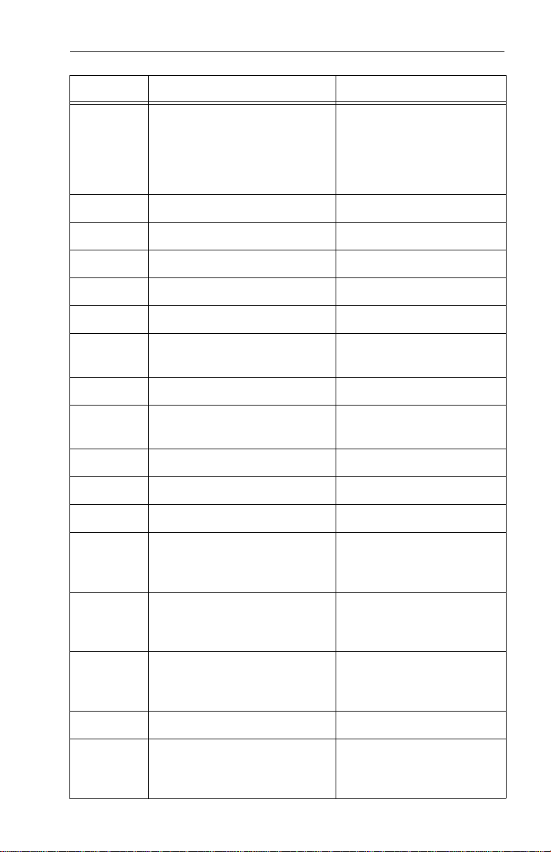
3.1.2 Identify Drive command
The Identify Drive command (command code ECH) transfer s information
about the drive to the host following power up. The data is organized as
a single 512-byte bl oc k of da ta, w hos e c on tents a re sh own in t he ta bl e
on page 25. All reserved bits or words should be set to zero. Parameters
listed with an “x” are drive-specific or vary with the state of the drive. See
Section 1 of this manual for default parameter settings.
The following commands contain drive-specific features that may not be
included in the Draft AT A -Rev 6 Stand ar d.
Page 33
ST320014A Product Manual, Rev. D 25
Word Description Value
Configuration information:
• Bit 15: 0 = ATA; 1 = ATAPI
0
• Bit 7: removable media
• Bit 6: removable controller
• Bit 0: reserved
0C5A
H
1 Number of logical cylinders
16,383
2 ATA-reserved C837
3 Number of logical heads
4 Retired 0000
5 Retired 0000
6 Number of logical sectors per
logical track: 63
003F
7–9 Retired 0000
10–19 Serial number: (20 ASCII
characters, 0000
= none) ASCII
H
20 Retired 0000
21 Retired 0400
22 Obsolete 0004
23–26 Firmware revision (8 ASCII
character string, padded with
blanks to end of string)
27–46 Drive model number: (40
ASCII characters, padded
ST320014A
with blanks to end of string)
H
16
H
H
H
H
H
H
H
x.xx
47 Maximum sectors per inter-
rupt on Read multiple and
Write multiple (32)
48 Reserved 0000
49 Standard Standby timer,
IORDY supported and may
be disabled
8010
2F00
H
H
H
Page 34

26 ST320014A Product Manual, Rev. D
Word Description Value
50 Device-specific standby
0000
timer value
51 PIO data-transfer cycle
timing mode 0200
52 Retired 0200
53 Words 54–58, 64–70 and 88
are valid
54 Number of current logical
0007
xxxx
cylinders
55 Number of current logical
xxxx
heads
56 Number of current logical
sectors per logical track
xxxx
57–58 Current capacity in sectors xxxx
59 Number of sectors trans-
ferred during a Read Multiple
xxxx
or Write Multiple command
60–61 Total number of user-addres-
sable LBA sectors available
(see Section 2.2.3 for related
ST320014A = 39,102,336
information)
H
H
H
H
H
H
H
H
H
62 Retired 0000
63 Multiword DMA active and
xx07
modes supported (see note
following this table)
64 Advanced PIO modes sup-
ported (modes 3 and 4
0003
supported)
65 Minimum multiword DMA
transfer cycle time per word
0078
(120 nsec)
H
H
H
H
Page 35

ST320014A Product Manual, Rev. D 27
Word Description Value
66 Recommended multiword
DMA transfer cycle time per
0078
H
word (120 nsec)
67 Minimum PIO cycle time
without IORDY flow control
00F0
H
(240 nsec)
68 Minimum PIO cycle time wi th
IORDY flow control (120
0078
H
nsec)
69–74 ATA-reserved 0000
75 Queue depth 0000
76–79 ATA-reserved 0000
80 Major version number 007E
81 Minor version number 0000
82 Command sets supported 346B
83 Command sets supported 4B09
84 Command sets support
4003
extension
85 Command sets enabled xxxx
86 Command sets enabled xxxx
87 Command sets enable
xxxx
extension
88 Ultra DMA support and
xx3F
current mode
(see note following this table)
89 Security erase time 0000
H
H
H
H
H
H
H
H
H
H
H
H
H
90 Enhanced security erase
time
91 Advanced Power Manage-
ment value
0000
0040
H
H
Page 36
28 ST320014A Product Manual, Rev. D
Word Description Value
92 Master Password Revision
FFFE
H
code
93 Hardware Reset Value
xxxx
H
(see description following
this table)
94 Auto Acoustic Management
xxxx
H
Setting
95–127 ATA-reserved 0000
128 Security Status 0001
129–159 Seagate-reserved xxxx
160–254 ATA-reserved 0000
255 Integrity word xxA5
H
H
H
H
H
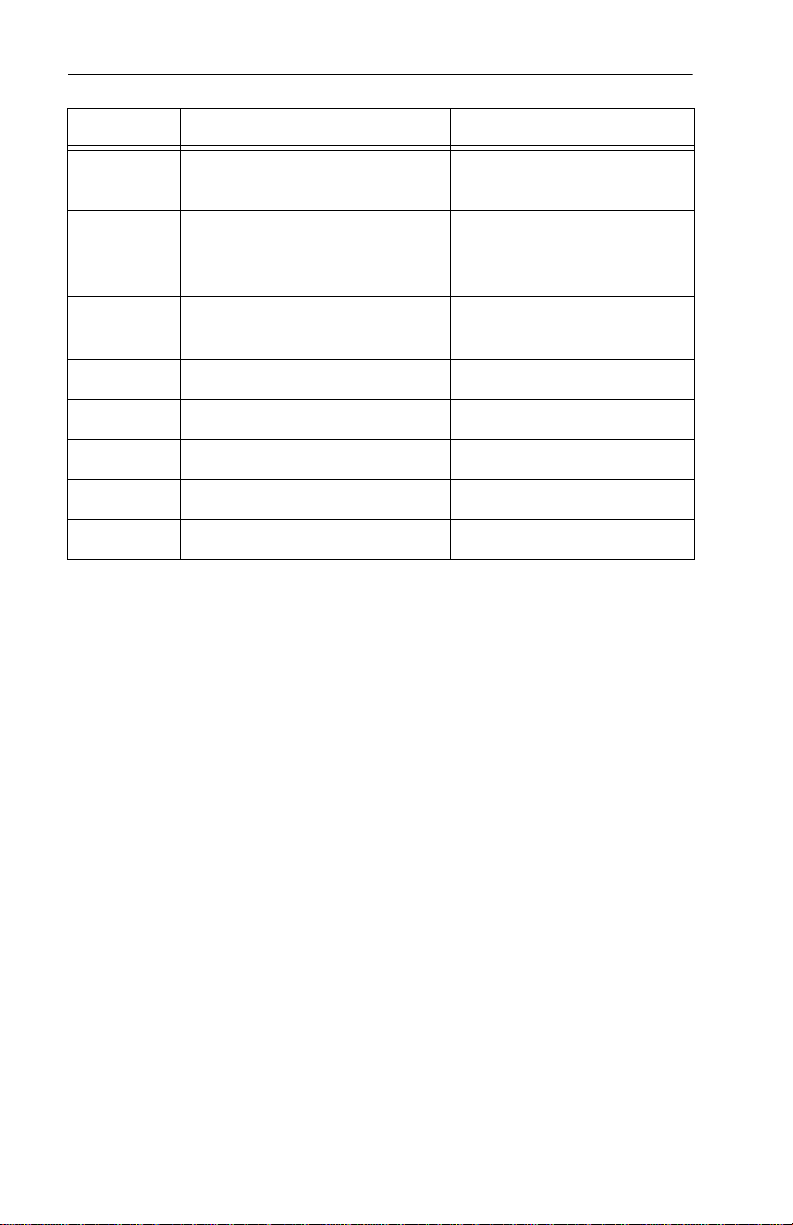
Note. See the bit descriptions belo w for words 63, 88 and 93 of the
Identify Drive data:
Description (if bit is set to 1)
Bit Word 63
0 Multiword DMA mode 0 is supported.
1 Multiword DMA mode 1 is supported.
2 Multiword DMA mode 2 is supported.
8 Multiword DMA mode 0 is currently active.
9 Multiword DMA mode 1 is currently active.
10 Multiword DMA mode 2 is currently active.
Bit Word 88
0 Ultra DMA mode 0 is supported.
1 Ultra DMA mode 1 is supported.
2 Ultra DMA mode 2 is supported.
3 Ultra DMA mode 3 is supported.
Page 37

ST320014A Product Manual, Rev. D 29
4 Ultra DMA mode 4 is supported.
5 Ultra DMA mode 5 is supported.
8 Ultra DMA mode 0 is currently active.
9 Ultra DMA mode 1 is currently active.
10 Ultra DMA mode 2 is currently active.
11 Ultra DMA mode 3 is currently active.
12 Ultra DMA mode 4 is currently active.
13 Ultra DMA mode 5 is currently active.
Bit Word 93
13 1 = 80-conductor cable detected, CBLID above VIH
0 = 40-conductor cable detected, CBLID below VIL
Bit Word 94
0–7 Current AAM setting
8–15 AAM Power on default
3.1.3 Set Features command
This command contr ols th e im pl eme ntation of various featu res th at th e
drive supports. When the drive receives this command, it sets BSY,
checks the contents of the Features register, clears BSY and generates
an interrupt. If the value in the register does not represent a feature that
the drive supports, th e command is aborted . Power-on d efault has the
read look-ahead and write caching features enabl ed. The acceptable
values for the Features register are defined as follows:
02
03
H
H
Enable write cache (default).
Set transfer mode (based on value in Sector Count register).
Sector Count register values:
00HSet PIO mode to default (PIO mode 2).
01HSet PIO mode to default and disable IORDY
(PIO mode 2).
08HPIO mode 0
09HPIO mode 1
Page 38

30 ST320014A Product Manual, Rev. D
0AHPIO mode 2
0BHPIO mode 3
0CHPIO mode 4 (default)
20HMultiword DMA mode 0
21HMultiword DMA mode 1
22HMultiword DMA mode 2
40HUltra DMA mode 0
41HUltra DMA mode 1
42HUltra DMA mode 2
43HUltra DMA mode 3
44HUltra DMA mode 4
45HUltra DMA mode 5
05
42
Enable advanced power management.
H
Auto Acoustic Management
H
FEHPerformance Seek
80HQuiet Acoustic Seek
55
82
AA
Disable read look-ahead (read cache) feature.
H
Disable write cache.
H
Enable read look-ahead (read cache) feature (default).
H
Note. At power-on, or after a hardware or software reset, the defaul t
values of the features are as indicated above.
Page 39

ST320014A Product Manual, Rev. D 31
3.1.4 S.M.A.R.T. commands
S.M.A.R.T. provides near-term failure prediction for disc drives. When
S.M.A.R.T. is enabled, the drive monitors pred etermined drive attributes
that are suscepti ble to degradation over time. If self-monitoring determines
that a failure is likely, S.M.A.R.T. makes a status report available to the
host. Not all failure s are predi ctable. S .M.A.R.T. predictabi lity is limited t o
the attributes the drive can monitor. For more information on S.M.A.R.T.
commands and implementation, see the Draft ATA-Rev 6 Stan dard .
SeaTools diagnostic software activates a built-in drive self-test (DST)
S.M.A.R.T. comman d for D4
The diagnostic software ships with all new drives and is also available at:
http://seatools.seagate.com.
This drive is shipped with S.M.A.R.T. features disabled. You must have
a recent BIOS or software pack age th at s upp orts S.M. A.R. T. to ena bl e
this feature. The table below shows the S.M.A.R.T. command codes that
the drive uses.
that eliminat es unnecessary drive ret urns.
H
Code in Features
S.M.A.R.T. Command
Register
D0
D1
D2
D3
D4
H
H
H
H
H
S.M.A.R.T. Read Data
Obsolete
S.M.A.R.T. Enable/Disable Attribute Autosave
S.M.A.R.T. Save Attribute Values
S.M.A.R.T. Execute Off-line Immediate
(runs DST)
D5
D6
D7
D8
D9
DA
H
H
H
H
H
H
S.M.A.R.T. Read Log Sector
S.M.A.R.T. Write Log Sector
Obsolete
S.M.A.R.T. Enable Operations
S.M.A.R.T. Disable Operations
S.M.A.R.T. Return Status
Note. If an appropriate code is not written to the Features Register, the
command is aborted and 0x04 (abort) is written to the Error
register.
Page 40

32 ST320014A Product Manual, Rev. D
Page 41

Page 42

Seagate Technology LLC
920 Disc Drive, Scotts Valley, California 95066-4544, USA
Publication Number: 100216020, Rev. D, Printed in USA
 Loading...