

Page 1

. . . . . . . . . . . . . . . . . . . . . . . . . . . . . . . . . . . . . . . . . . . . . . . . .
Hawk 2XL Disc Drive
. . . . . . . . . . . . . . . . . . . . . . . . . . . . . . . . . . . . . . . . . . . . . . . . .
. . . . . . . . . . . . . . . . . . . . . . . . . . . . . . . . . . . . . . . . . . . . . . . . .
. . . . . . . . . . . . . . . . . . . . . . . . . . . . . . . . . . . . . . . . . . . . . . . . .
. . . . . . . . . . . . . . . . . . . . . . . . . . . . . . . . . . . . . . . . . . . . . . . . .
. . . . . . . . . . . . . . . . . . . . . . . . . . . . . . . . . . . . . . . . . . . . . . . . .
ST32151N/W/WC, ST31051N/W/WC
ST32155N/W/WC, ST31055N/W/WC
Product Manual, Volume 1
Page 2

Page 3

. . . . . . . . . . . . . . . . . . . . . . . . . . . . . . . . . . . . . . . . . . . . . . . . .
Hawk 2XL Disc Drive
. . . . . . . . . . . . . . . . . . . . . . . . . . . . . . . . . . . . . . . . . . . . . . . . .
. . . . . . . . . . . . . . . . . . . . . . . . . . . . . . . . . . . . . . . . . . . . . . . . .
. . . . . . . . . . . . . . . . . . . . . . . . . . . . . . . . . . . . . . . . . . . . . . . . .
. . . . . . . . . . . . . . . . . . . . . . . . . . . . . . . . . . . . . . . . . . . . . . . . .
. . . . . . . . . . . . . . . . . . . . . . . . . . . . . . . . . . . . . . . . . . . . . . . . .
ST32151N/W/WC, ST31051N/W/WC
ST32155N/W/WC; ST31055N/W/WC
Product Manual, Volume 1
Page 4

© 1996 Seagate Technology, Inc. All right s reserved
April 1996
Publication number: 77767489, Rev. B
Seagate®, Seagate Technology® , and the Seagate logo are r egistered tradema rks of Seagate
TM
Technology, Inc. Elite
, SeaFAXTM, SeaFONETM, SeaTDDTM, and SeaBOARDTM are trademarks of Seagate Technology, Inc. Other product names are registered trademarks or trademarks of their owners.
No part of this publication may be reproduced in any form without written permission from
Seagate Technology, Inc.
Printed in the United States of America
Page 5

Revision status summary sheet
Revision Date Writer/Engineer Sheets Affected
A 5/2/96 D. Ashby 1-75
B Ashby and Kiene 9, 23 and 25
Product Man ual 77767489 is V olum e 1 of a two Vol ume docu ment w ith the SCS I In terface in formati on
in the Volume 2 SCSI Interface Product Manu al, P/N 7773847 9.
If the SCSI Interface information is needed the Volume 2 Interface Manual should be ordered, P/N
77738479.
Page 6

Page 7

Hawk 2XL Product M anu al, Rev. B vii
Conten ts
1.0 Scope . . . . . . . . . . . . . . . . . . . . . . . . . . . . . . . . . . . . . . . . . . . . . . . . . . . . . . . . . . . . . . . . . . . . . . . . . . 1
2.0 Applicable standards and reference documentati on. . . . . . . . . . . . . . . . . . . . . . . . . . . . . . . . . . . . 3
2.1 Standards. . . . . . . . . . . . . . . . . . . . . . . . . . . . . . . . . . . . . . . . . . . . . . . . . . . . . . . . . . . . . . . . . 3
2.1.1 Electromagnetic com pati bili ty . . . . . . . . . . . . . . . . . . . . . . . . . . . . . . . . . . . . . . . . . . 3
2.1.2 Electromagnetic susceptibility . . . . . . . . . . . . . . . . . . . . . . . . . . . . . . . . . . . . . . . . . . 3
2.2 Electromagne tic Com plia nce for the European Uni on . . . . . . . . . . . . . . . . . . . . . . . . . . . . . . . 3
2.3 Reference documents . . . . . . . . . . . . . . . . . . . . . . . . . . . . . . . . . . . . . . . . . . . . . . . . . . . . . . . 4
3.0 General descri p tion . . . . . . . . . . . . . . . . . . . . . . . . . . . . . . . . . . . . . . . . . . . . . . . . . . . . . . . . . . . . . . . 5
3.1 Standard features. . . . . . . . . . . . . . . . . . . . . . . . . . . . . . . . . . . . . . . . . . . . . . . . . . . . . . . . . . . 7
3.2 Media characteristic s . . . . . . . . . . . . . . . . . . . . . . . . . . . . . . . . . . . . . . . . . . . . . . . . . . . . . . . . 7
3.3 Performance. . . . . . . . . . . . . . . . . . . . . . . . . . . . . . . . . . . . . . . . . . . . . . . . . . . . . . . . . . . . . . . 7
3.4 Reliability . . . . . . . . . . . . . . . . . . . . . . . . . . . . . . . . . . . . . . . . . . . . . . . . . . . . . . . . . . . . . . . . . 7
3.5 Unformatt ed and formatt ed capacit ies . . . . . . . . . . . . . . . . . . . . . . . . . . . . . . . . . . . . . . . . . . . 8
3.6 Factory installed accessories . . . . . . . . . . . . . . . . . . . . . . . . . . . . . . . . . . . . . . . . . . . . . . . . . . 8
3.7 Options (factory install ed ) . . . . . . . . . . . . . . . . . . . . . . . . . . . . . . . . . . . . . . . . . . . . . . . . . . . . . 8
3.8 Accessories (user installed) . . . . . . . . . . . . . . . . . . . . . . . . . . . . . . . . . . . . . . . . . . . . . . . . . . . 8
4.0 Performa nce cha racteri sti c s . . . . . . . . . . . . . . . . . . . . . . . . . . . . . . . . . . . . . . . . . . . . . . . . . . . . . . . 9
4.1 Internal drive characteristics (transparent to user). . . . . . . . . . . . . . . . . . . . . . . . . . . . . . . . . . 9
4.2 SCSI Seek performance characteristics (visible to user) [6]*. . . . . . . . . . . . . . . . . . . . . . . . . . 9
4.2.1 Access time . . . . . . . . . . . . . . . . . . . . . . . . . . . . . . . . . . . . . . . . . . . . . . . . . . . . . . . 9
4.2.2 Format command executi on time (min ute s) [1] . . . . . . . . . . . . . . . . . . . . . . . . . . . 10
4.2.3 Generalized performance characteristics . . . . . . . . . . . . . . . . . . . . . . . . . . . . . . . . 10
4.3 Start/st op tim e . . . . . . . . . . . . . . . . . . . . . . . . . . . . . . . . . . . . . . . . . . . . . . . . . . . . . . . . . . . . 11
4.4 Prefetch/multi-segmented cache control . . . . . . . . . . . . . . . . . . . . . . . . . . . . . . . . . . . . . . . . 11
4.5 Cache operation. . . . . . . . . . . . . . . . . . . . . . . . . . . . . . . . . . . . . . . . . . . . . . . . . . . . . . . . . . . 11
4.5.1 Caching write data . . . . . . . . . . . . . . . . . . . . . . . . . . . . . . . . . . . . . . . . . . . . . . . . . 12
4.5.2 Prefetch operation . . . . . . . . . . . . . . . . . . . . . . . . . . . . . . . . . . . . . . . . . . . . . . . . . 12
5.0 Reliability sp eci ficati on s . . . . . . . . . . . . . . . . . . . . . . . . . . . . . . . . . . . . . . . . . . . . . . . . . . . . . . . . . 15
5.1 Error rates . . . . . . . . . . . . . . . . . . . . . . . . . . . . . . . . . . . . . . . . . . . . . . . . . . . . . . . . . . . . . . . 15
5.1.1 Environmental interference. . . . . . . . . . . . . . . . . . . . . . . . . . . . . . . . . . . . . . . . . . . 15
5.1.2 Read errors. . . . . . . . . . . . . . . . . . . . . . . . . . . . . . . . . . . . . . . . . . . . . . . . . . . . . . . 15
5.1.3 Write errors . . . . . . . . . . . . . . . . . . . . . . . . . . . . . . . . . . . . . . . . . . . . . . . . . . . . . . . 15
5.1.4 Seek errors. . . . . . . . . . . . . . . . . . . . . . . . . . . . . . . . . . . . . . . . . . . . . . . . . . . . . . . 16
5.2 Reliability and service . . . . . . . . . . . . . . . . . . . . . . . . . . . . . . . . . . . . . . . . . . . . . . . . . . . . . . . 16
5.2.1 Mean time between failure . . . . . . . . . . . . . . . . . . . . . . . . . . . . . . . . . . . . . . . . . . . 16
5.2.2 Preventive maintenance . . . . . . . . . . . . . . . . . . . . . . . . . . . . . . . . . . . . . . . . . . . . . 16
5.2.3 Service life . . . . . . . . . . . . . . . . . . . . . . . . . . . . . . . . . . . . . . . . . . . . . . . . . . . . . . . 16
5.2.4 Service philosophy . . . . . . . . . . . . . . . . . . . . . . . . . . . . . . . . . . . . . . . . . . . . . . . . . 16
5.2.5 Service tools. . . . . . . . . . . . . . . . . . . . . . . . . . . . . . . . . . . . . . . . . . . . . . . . . . . . . . 16
5.2.6 Product warranty . . . . . . . . . . . . . . . . . . . . . . . . . . . . . . . . . . . . . . . . . . . . . . . . . . . 16
6.0 Physical/electrical specifications . . . . . . . . . . . . . . . . . . . . . . . . . . . . . . . . . . . . . . . . . . . . . . . . . . 19
6.1 AC power requirements . . . . . . . . . . . . . . . . . . . . . . . . . . . . . . . . . . . . . . . . . . . . . . . . . . . . . 19
6.2 DC power requirements . . . . . . . . . . . . . . . . . . . . . . . . . . . . . . . . . . . . . . . . . . . . . . . . . . . . . 19
6.2.1 Conducted noise immunity . . . . . . . . . . . . . . . . . . . . . . . . . . . . . . . . . . . . . . . . . . . 19
6.2.2 Power sequencing . . . . . . . . . . . . . . . . . . . . . . . . . . . . . . . . . . . . . . . . . . . . . . . . . 20
6.2.3 Current profile . . . . . . . . . . . . . . . . . . . . . . . . . . . . . . . . . . . . . . . . . . . . . . . . . . . . . 20
6.3 Power dissipation . . . . . . . . . . . . . . . . . . . . . . . . . . . . . . . . . . . . . . . . . . . . . . . . . . . . . . . . . . 21
6.4 Environmenta l limits . . . . . . . . . . . . . . . . . . . . . . . . . . . . . . . . . . . . . . . . . . . . . . . . . . . . . . . . 21
6.4.1 Temperature . . . . . . . . . . . . . . . . . . . . . . . . . . . . . . . . . . . . . . . . . . . . . . . . . . . . . . 21
6.4.2 Relative humidit y . . . . . . . . . . . . . . . . . . . . . . . . . . . . . . . . . . . . . . . . . . . . . . . . . . 22
6.4.3 Effective altitude (sea level) . . . . . . . . . . . . . . . . . . . . . . . . . . . . . . . . . . . . . . . . . . 23
6.4.4 Shock and vibration . . . . . . . . . . . . . . . . . . . . . . . . . . . . . . . . . . . . . . . . . . . . . . . . 23
6.4.5 Air cleanliness. . . . . . . . . . . . . . . . . . . . . . . . . . . . . . . . . . . . . . . . . . . . . . . . . . . . . 25
Page 8

viii Hawk 2XL Pr odu ct Man ual , Rev. B
6.4.6 Electromagnetic susceptibility . . . . . . . . . . . . . . . . . . . . . . . . . . . . . . . . . . . . . . . . .25
6.5 Mechanical specif icati ons . . . . . . . . . . . . . . . . . . . . . . . . . . . . . . . . . . . . . . . . . . . . . . . . . . . .26
7.0 Defect and error man agem e nt . . . . . . . . . . . . . . . . . . . . . . . . . . . . . . . . . . . . . . . . . . . . . . . . . . . . .29
7.1 Drive internal defects and erro rs . . . . . . . . . . . . . . . . . . . . . . . . . . . . . . . . . . . . . . . . . . . . . . .29
7.2 SCSI systems errors . . . . . . . . . . . . . . . . . . . . . . . . . . . . . . . . . . . . . . . . . . . . . . . . . . . . . . . .29
8.0 Installati on . . . . . . . . . . . . . . . . . . . . . . . . . . . . . . . . . . . . . . . . . . . . . . . . . . . . . . . . . . . . . . . . . . . . .31
8.1 Drive ID/option select h ea der . . . . . . . . . . . . . . . . . . . . . . . . . . . . . . . . . . . . . . . . . . . . . . . . .31
8.1.1 Notes for Figures 7a, 7b, 7c, 7d and 7e. . . . . . . . . . . . . . . . . . . . . . . . . . . . . . . . . .36
8.1.2 Function description. . . . . . . . . . . . . . . . . . . . . . . . . . . . . . . . . . . . . . . . . . . . . . . . .37
8.2 Drive orientation . . . . . . . . . . . . . . . . . . . . . . . . . . . . . . . . . . . . . . . . . . . . . . . . . . . . . . . . . . .38
8.3 Cooling . . . . . . . . . . . . . . . . . . . . . . . . . . . . . . . . . . . . . . . . . . . . . . . . . . . . . . . . . . . . . . . . . .38
8.3 .1 Air fl o w . . . . . . . . . . . . . . . . . . . . . . . . . . . . . . . . . . . . . . . . . . . . . . . . . . . . . . . . . . .38
8.4 Drive mounting . . . . . . . . . . . . . . . . . . . . . . . . . . . . . . . . . . . . . . . . . . . . . . . . . . . . . . . . . . . .38
8.5 Grounding . . . . . . . . . . . . . . . . . . . . . . . . . . . . . . . . . . . . . . . . . . . . . . . . . . . . . . . . . . . . . . . .38
9.0 Interface requirem en ts . . . . . . . . . . . . . . . . . . . . . . . . . . . . . . . . . . . . . . . . . . . . . . . . . . . . . . . . . . . .41
9.1 General description . . . . . . . . . . . . . . . . . . . . . . . . . . . . . . . . . . . . . . . . . . . . . . . . . . . . . . . . .41
9.2 SCSI interface messag es supported. . . . . . . . . . . . . . . . . . . . . . . . . . . . . . . . . . . . . . . . . . . .41
9.3 SCSI interface command s supported . . . . . . . . . . . . . . . . . . . . . . . . . . . . . . . . . . . . . . . . . . .42
9.3.1 Inquiry data . . . . . . . . . . . . . . . . . . . . . . . . . . . . . . . . . . . . . . . . . . . . . . . . . . . . . . .44
9.3.2 Mode Sense data. . . . . . . . . . . . . . . . . . . . . . . . . . . . . . . . . . . . . . . . . . . . . . . . . . .45
9.4 SCSI bus conditions and miscellaneous features support ed . . . . . . . . . . . . . . . . . . . . . . . . .48
9.5 Synchronous data transfer . . . . . . . . . . . . . . . . . . . . . . . . . . . . . . . . . . . . . . . . . . . . . . . . . . .49
9.5.1 Synchronous data transfer periods supported. . . . . . . . . . . . . . . . . . . . . . . . . . . . .49
9.5.2 REQ/ACK offset. . . . . . . . . . . . . . . . . . . . . . . . . . . . . . . . . . . . . . . . . . . . . . . . . . . .49
9.6 Physica l interf ac e . . . . . . . . . . . . . . . . . . . . . . . . . . . . . . . . . . . . . . . . . . . . . . . . . . . . . . . . . .49
9.6.1 DC cable and connector . . . . . . . . . . . . . . . . . . . . . . . . . . . . . . . . . . . . . . . . . . . . .49
9.6.2 SCSI Interface physical description. . . . . . . . . . . . . . . . . . . . . . . . . . . . . . . . . . . . .52
9.6.3 SCSI Interface Cable requirements . . . . . . . . . . . . . . . . . . . . . . . . . . . . . . . . . . . . .52
9.6.4 Mating connectors . . . . . . . . . . . . . . . . . . . . . . . . . . . . . . . . . . . . . . . . . . . . . . . . . .53
9.7 Terminator re quirem ents . . . . . . . . . . . . . . . . . . . . . . . . . . . . . . . . . . . . . . . . . . . . . . . . . . . . .63
9.8 Terminator power . . . . . . . . . . . . . . . . . . . . . . . . . . . . . . . . . . . . . . . . . . . . . . . . . . . . . . . . . .63
9.9 Disc drive SCSI timing. . . . . . . . . . . . . . . . . . . . . . . . . . . . . . . . . . . . . . . . . . . . . . . . . . . . . . .64
10.0 Technical supp or t service . . . . . . . . . . . . . . . . . . . . . . . . . . . . . . . . . . . . . . . . . . . . . . . . . . . . . . . . .67
Page 9

Hawk 2XL Product M anu al, Rev. B ix
List of Figures
Figure 1. Hawk 2XL family drive . . . . . . . . . . . . . . . . . . . . . . . . . . . . . . . . . . . . . . . . . . . . . . . . . . . . . . . 2
Figure 2. Hawk 2XL family drive . . . . . . . . . . . . . . . . . . . . . . . . . . . . . . . . . . . . . . . . . . . . . . . . . . . . . . . 6
Figure 3. Typical Hawk 2XL family drive +5 V and +12 V current profile . . . . . . . . . . . . . . . . . . . . . . . 20
Figure 4. Locations of components (listed in Table 3). . . . . . . . . . . . . . . . . . . . . . . . . . . . . . . . . . . . . . 22
Figure 5. Recommended mounti ng (Appl icable to all Hawk 2XL family models) . . . . . . . . . . . . . . . . . 24
Figure 6a. Mounting confi gurati on dim ensions for m odel “ N” . . . . . . . . . . . . . . . . . . . . . . . . . . . . . . . . . 26
Figure 6b. Mounting confi gurati on dim ensions for m odel “W ”. . . . . . . . . . . . . . . . . . . . . . . . . . . . . . . . . 27
Figure 6c. Mo unti ng co nfi gurati on dim ensions for model “WC” . . . . . . . . . . . . . . . . . . . . . . . . . . . . . . . 28
Figure 7a. Hawk 2XL family drive ID select header for model “N”. . . . . . . . . . . . . . . . . . . . . . . . . . . . . . 32
Figure 7b. Hawk 2XL family drive ID select for models “W” and “WC” . . . . . . . . . . . . . . . . . . . . . . . . . . 33
Figure 7c. Hawk 2XL family drive ID select header J1-auxiliary for model “W” (J1-Aux. Pins 1A-12A) . 34
Figure 7d. Hawk 2XL family drive option select header for models “N” and “W”. . . . . . . . . . . . . . . . . . . 35
Figure 7e. Hawk 2XL family drive option select header for model “WC”. . . . . . . . . . . . . . . . . . . . . . . . . 35
Figure 8. Air flow (suggested) . . . . . . . . . . . . . . . . . . . . . . . . . . . . . . . . . . . . . . . . . . . . . . . . . . . . . . . . 39
Figure 9a. Physical interface for “N” model drives . . . . . . . . . . . . . . . . . . . . . . . . . . . . . . . . . . . . . . . . . . 50
Figure 9b. Model “W” drive physical interface (68 pin J1 SCSI I/O connector) . . . . . . . . . . . . . . . . . . . . 51
Figure 9c. Mo del “WC” drive physical interface (80 pin J1 SCS I I/O connector / DC power connector) 51
Figure 10. SCSI Daisy-chain interface cabling . . . . . . . . . . . . . . . . . . . . . . . . . . . . . . . . . . . . . . . . . . . . 54
Figure 11a. Nonshielded 50 pin S CSI device connector. . . . . . . . . . . . . . . . . . . . . . . . . . . . . . . . . . . . . . 55
Figure 11b. Nonshielded 68 pin S CSI device connector. . . . . . . . . . . . . . . . . . . . . . . . . . . . . . . . . . . . . . 56
Figure 11c. Nonshielded 80 pin SCSI connector, used on “WC” model . . . . . . . . . . . . . . . . . . . . . . . . . . 57
Figure 12. Single-ended transmitters and receivers . . . . . . . . . . . . . . . . . . . . . . . . . . . . . . . . . . . . . . . . 62
Page 10

Page 11

Hawk 2XL Product M anu al, Rev. B 1
1.0 Scope
This manual describes the Seagate Technology, Inc. Hawk 2XL fam ily of disc drives. This high capacity, hig h
performance member of the Seagate 1-inch high 3.5-inch rigid disk family is a next generation product from the
Hawk 2LP (ST34230) disc drive. The Hawk 2XL features a new cost-optimized HDA, reduced cost SCSI code,
reduced header fields and t he use of innovat ive technology i n the embedde d servo, R/W heads, read circuits
and SCSI controller. Sectio n 5 lists performance informati on for this drive. The Hawk 2XL drive operates an
interface to the ho st defined by a subset of AN SI SCSI 2/SCSI 3 as described in Section 9 of this manual
(Vol.1) and the Seagate SCSI Interface manual 77738479 (V ol. 2).
The Hawk 2XL family consists of ST32151, ST31 051, ST32155 and ST31055 product s. Models of fered are N,
W, and WC.
Table 1 lists the salient features that differentiate the different Hawk 2XL model num bers.
Table 1: Drive model number vs. differentiati ng feature s
Fast SCSI-3
Model number # Heads I/O Ckts
#I/O
connector
I/O data bus bits
ST32151N 8 single-ended 50 8 10
ST32151W 8 single-ended 68 16 20
ST32151WC 8 single-ended 80 16 20
ST31051N 4 single-ended 50 8 10
ST31051W 4 single-ended 68 16 20
ST31051WC 4 single-ended 80 16 20
ULTRA SCSI-3 [1]
Model number # Heads I/O Ckts
#I/O
connector
I/O data bus bits
ST32155N 8 single-ended 50 8 20
ST32155W 8 single-ended 68 16 40
ST32155WC 8 single-ended 80 16 40
ST31055N 4 single-ended 50 8 20
ST31055W 4 single-ended 68 16 40
ST31055WC 4 single-ended 80 16 40
Interface Data
transfer rate
(Mbytes/sec)
Interface Data
transfer rate
(Mbytes/sec)
From this point on in this Product Manual the reference to Hawk 2XL family models is referred to as “the drive”
(unless reference to individual models are necessary).
The drive printed circuit board is referred to as a PCB.
[1] ULTRA SCSI is Seaga te’ s name for th e ANS I propo se d “FAS T -20” i nterf ace.
Page 12
2 Hawk 2XL Product Man ual , Rev. B
.
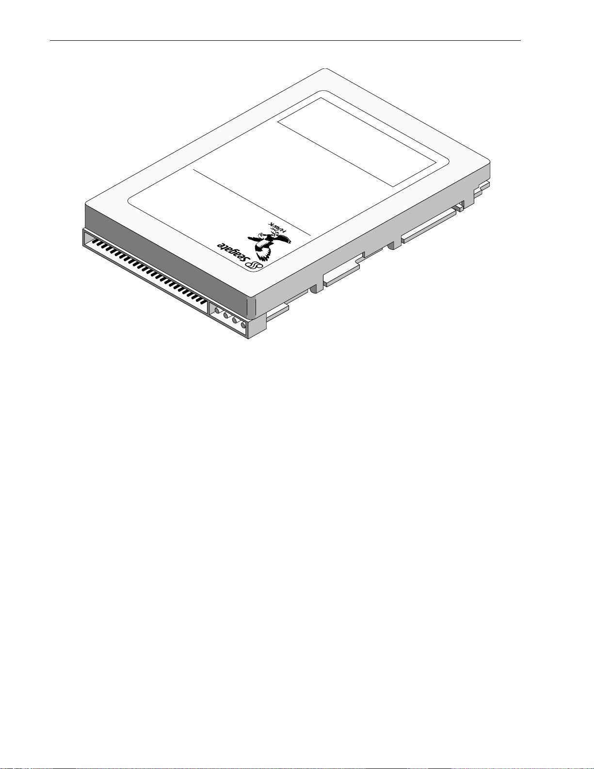
*
*Model “N” version with 50 pin SCSI I/O connector
Figure 1. Hawk 2XL family dri ve
Page 13

Hawk 2XL Product M anu al, Rev. B 3
2.0 Applicable standards and reference documentation
The drive has been developed as a system peripheral to the highest standards of design and construction. The
drive depends upon its host equipm ent to provide adequate power and environm ent in order to achieve optimum performance a nd compliance with applicable indust ry and governmental regulations. Specia l attention
must be given in the areas of safety, power distribution, shield ing, audible noise control, and t emp erature regulation. In particular, the drive must be securely mounted in order to guarantee the specified performance characteristics. Mounting by bott om holes must meet the requirement s of Section 8.4.
2.1 Standards
The Hawk 2XL Family comp lies with Seagate standards as note d in the appropriate sections of this Manual
and the Seagate SCSI Interface Manual, P/N 77738479 (Vol. 2).
The Hawk 2XL Family is a UL R eco gnized com pone nt per UL 1950 and a CSA Certified com ponen t per CAN/
CSA-C22.2 No. 950-M89. It also meets the requirements of DIN VDE 0805/05 .90 and EN60950: 1988 (IEC
950).
2.1.1 Electromagnetic compatibility
The drive, as delivered, is designed for s ystem integrati on and installation into a suitable enclosure prior to
use. As such the drive is supplied as a subas sembly and is not subject to Subpart J of Part 15 of the FCC
Rules and Regulations nor the Radio Interference Regulations of the Canadian Departmen t of Communications. However, the un it has been test ed using proper shiel ding and groun ding a nd found t o be compl iant wit h
Class A limits of the FCC Rules and the Regulations of the Canadian Departme nt of Comm unicat ions.
The physical design characteristi cs of the drive serve to minim ize radia tion when installed in an enclosure that
provides reasonable shielding. As such, the drive is capable of meeting the Class B limits of the FCC Rules
and Regulations o f the Canadian Department of Communi cation. However, it is the user’s responsibility to
assure that the drive m eets the appropriate EMI requirements in their system. S hielded I/O cables may b e
required if the enclosure does not provide adequate shielding. If the I/O cables are external to the enclosure,
shielded cables should be used, with the shields grounded to the enclosure or to the host controller, but not
both.
2.1.2 Electromagnetic susceptibility
As a component assembly, the drive is not required to meet any susceptibility performance requirements. It is
the responsibility of those inte grati ng the drive wi thin their system s t o perform t hose test s required a nd desig n
their system to ensure that equipmen t operating in the same system as the drive or external to the system
does not adversely affect the performance of the drive. See Section 5.1.1 and Table 2, DC power requirements.
2.2 Electromag netic Com plia nce for the E uro pe an Uni on
If this model has the CE Marking it complies with the European Union requirements of the Electrom agnetic
Compatibility Di re ctive 89/3 36/ EEC o f 03 M ay 1989 as am ende d by Dire ctive 92/3 1/EEC of 28 A pril 1 992 an d
Directive 93/68/E E C of 22 Jul y 199 3.
Seagate uses an indepen dent laboratory t o confirm compli ance to the above d irectives. The drive was t ested
in a representative system for typical appl ications. The select ed system represents the most pop ular characteristics for test platforms The system configurat ions includ e:
• 486, Pentium, and PowerPC Microprocessors
• 3.5-inch Floppy Disc Drive
• Keyboard
• Monitor/Display
Although the test system with this Seagat e model com plies to the direct ives, we cannot guarant ee that al l sys-
tems will compl y. The computer manuf acturer or system integrator shall conform EMC compliance and provide
CE Marking for their product.
Page 14

4 Hawk 2XL Product Man ual , Rev. B
2.3 Reference documents
Installation Guide Seagate P/N 77767490
SCSI Interface Manual Seagate P/N 77738479
ANSI Small Co mputer System Interface (SCSI): Document Numbe r ANSI3.131-1986 (X3T9/84.40 Rev. 1B)
(X3T9.2/82-2 Rev. 17B), X3T9.2/86-109 Revision 10H (SCSI-2) and X3T9.2-184 Rev. 4 (SCSI-3).
ANSI - draft proposed: Document Number X3T10/ 1071 D, SCSI-3 FA ST-20 revision 6.
Package Test Specification Seagate P/N 30190-001 (under 100 lb.)
Package Test Specif icati on Seagate P/N 30191-001 (over 100 lb.)
In case of conflict between this document and any referenced documen t, this document takes precedence.
Page 15

Hawk 2XL Product M anu al, Rev. B 5
3.0 General description
The drives are a member of a family of low cost, high performance, highly reliable , random access storage
devices designed to meet the needs of the OEM marketplace.
The drive records and recovers data on 3.5 inch (89 mm) fixed discs.
The drive supports the Sma ll Computer S ystem Interface a s described in the ANSI SCSI-2 and SCS I-3 Int er-
face Manuals to the e xtent described in this product Man ual (Vol. 1), which def ines the product perform ance
characteristics of the Hawk 2XL Family of drives, and the SCSI Interface Product Manual P/N 77738479
(Vol.2, Version 2) which describes the general interface characteristics of this and other fa milies of Seagate
3.5-inch drives.
The drive interface supports multiple initiators, disconnect/reconn ect, self-configuring host software and auto-
matic features th at relieve the host from the necessity of knowing the physical characteristics of the targets
(logical block addressing is used).
TheHead/Disc Assembly (HDA ) is environm entally seal ed at the factory. Air recirculates wit hin the Head/ Disc
(HDA) through a nonreplaceable filter to maintain a contam inat ion free head/d isc environmen t.
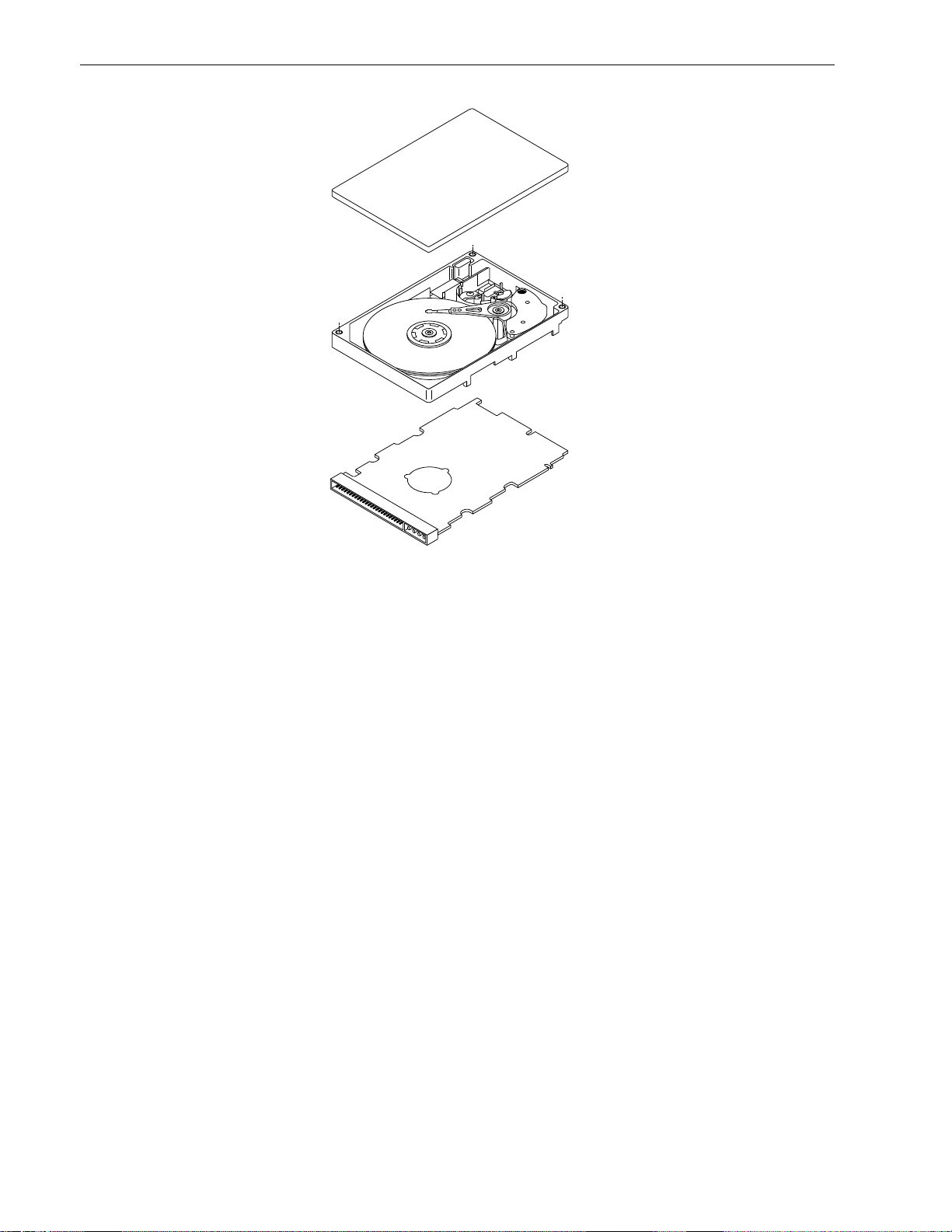
Refer to Figure 2, an exploded view of the drive. NEVER disassemble the Head/Disc Assembly (HDA). This
exploded view is for inf ormation on ly. Do not att empt to service items in t he sealed environm ental encl osure
(heads, media, actuat or, e tc. ) as t his requires special faci lities. The drive contains no pa rts repl aceable by th e
user. The drive warranty is voided if the HDA is opened.
The Hawk 2XL Fam ily drives use a dedicated landing zon e at the innermost radius of the m edia to eliminate
the possibility of destroying or d e grading data by landing in the d ata zone. The drive automatical ly goes t o the
landing zone when the power is removed.
The Hawk 2XL Fam ily drives incorporate an au tomatic shipping lock which p revents potent ial damage to the
heads and dis cs that result from movement during shipping an d handling. The sh ipping lock is autom atically
disengaged when power is applied to the drive and the head load process begins.
The Hawk 2XL Fam ily drives decode track lo cation from the servo data embedded on each surface to el iminate mechanical transducer adjustm ent s and related reliabilit y concern s.
The Hawk 2XL Fam ily drives use a high performance actuat or assembly that consists of a low inertia, b alanced, patented, straigh t arm design that provides excellent performance w ith minim um power dissipation.
Page 16
6 Hawk 2XL Product Man ual , Rev. B
Figure 2. Hawk 2XL family dri ve
Page 17

Hawk 2XL Product M anu al, Rev. B 7
3.1 Standard features
The Hawk 2XL Family has the following standard f eatu res:
• Integrated SCSI Contro ller wit h reduce d comple xity SCS I code
• Single-ended SCSI drivers and receivers
• Asynchronous and Synchronous data transfer protocol
• Firmware downloadable via SCSI interfa ce
• Flawed sector reallocation at format time
• Programmable auto write and read reallocation
• Reallocation of defects on comm and (P ost Format )
• 96 bit Reed-Solomon error correcting code
• Sealed Head/Disc Assembly
• No preventative maintenance or adjust men t required
• Dedicated head landing zone
• Embedded servo data rather than a separate servo data surfa ce
• Self diagnostics performe d at power on
• 1:1 Interleave
• Zoned Bit Recording (ZBR)
• Vertical, horizontal, or top down mounting
• Dynamic spindle brake
• Permanentl y mount ed term inators on “N” and “W” mode ls, enabl ed by install ati on of a jumper plug.
• 256 K byte data buffer (512K byte data buf fer for “W” and “W C” models and all Ultra SCSI mod els)
• Hot Plug compatibility (Sect ion 9.6.4.3 lists proper host connector needed)
• SCAM plug-n-play complia nt [1]
• ULTRA SCSI (Models ST3 2155 and S T310 55 )
3.2 Media characteristics
The media used on the drive has a diameter of approximately 3.5 inches (89 mm). The aluminum substrate is
coated with a thin film magnet ic m ateri al, overcoate d with a propriet ary prot ective layer for im proved durab ility
and environmental protectio n.
3.3 Performa nce
• Programmable multi-segmentable cache buffer
• 5411 RPM Spindle. Average lat ency = 5.54 msec
• Command Queuing of up to 64 commands
• Background processing of queue
• Supports start and stop commands (spindle stops sp innin g)
• Low audible noise for office environment
• Low power consumption
3.4 Reliability
• 800,000 hour MTBF
• Adaptive servo calibration for improved seek performance
• LSI circuitry
• Balanced low mass rotary voice coil actuator
• 5 year warranty for ST32151 and ST32155; 3 year warranty for ST31051 and ST31055
[1] Supports SCAM L evel 1 at the moment. Will support Level 2 when all prese ntly unresolved requirements
are fully defined. As a factory instal led option SC AM can be turned off.
Page 18

8 Hawk 2XL Product Man ual , Rev. B
3.5 Unformatted and formatted cap aci ties
Formatted ca pacity depends on the number of spare real location sectors reserved and the number o f bytes
per sector. The following table shows some typical 512 byte sector size [1] formatted capacit ies (rounded off).
ST32151 GB
ST32155 GB
ST31051 GB
ST31055 GB
Spare Sector or Cylinders
Reserved for reallocation
No Spares 2.18 1.07
Five Spare Sectors per Cylinder [2] - 1.0 6
Ten Spare Sectors per Cylinder [2] 2.15 -
The standard OEM model is as follows:
Formatted
Data Block Size
512 Byte/Sector
Unformatted
ST32151/ST32155 2.148 GB[4] 2.54 GB
ST31051/ST31055 1.060 GB[5] 1.26 GB
Notes.
[1] Sector size selectable when formatted at factory.
[2] All spare sectors are on one track.
[3] Spare cylinders are on the two inner tracks.
[4] Sparing equivalent t o eight spare sect or per c ylinder (all spare sectors are on one track), two spa re cylin-
ders/unit.[3]
[5] Sparing equivalent to five sp are sectors per cylinde r (all spa re sectors a re on o ne track), two spare cyl in-
ders/unit.[3]
3.6 Factory installed accesso rie s
OEM Standard drives are shipped with Installation Guide P/ N 77767490 (unles s otherwise specified). The factory also ships with the drive a s ma ll bag of the two j um per plug types used for the o ption select jum per he aders.
3.7 Options (factory in stal led )
All customer requested options are incorporated during production o r packaged at the manufacturing f acility
before shipping. Some of the options availabl e are (not an exhausti ve list of possible options):
• The capacities shown in Section 3.5 . Other capacities can be ordered depending on sparing scheme and
sector size requested.
• Black plastic front panel. Other panel colors may be specially ordered. Panel has a green, rectangular LED
drive activity indicator lens. The indicator glows whe n the drive is selected.
• Single unit ship ping pack. The dri ve is normally shipped in bulk packag ing to provide maxim um protectio n
against transit damage. Units shipped individually require additional protection as provided by the single unit
shipping pack. Users planning single unit distribut ion should specif y this option.
• The Installa tion Gui de (P /N 77767490 ) is usuall y included with each st andard O EM dri ve shipped , but extra
copies may be ordered.
3.8 Accessories (user installe d)
The following accessories are available. All accessories may be installed in the field.
• Front Panel Kit (with green rectangular LED lens).
• Single unit shipping pack.
• Adapter Accessory Frame Kit P/N 75790701. This kit ad apts a 3.5 inch Model “N” and “W” drives to fit in a
5.25 inch drive mounting space. The frame does not work for “WC” model drives which plug directly into a
bulkhead or backplane connector.
Page 19

Hawk 2XL Product M anu al, Rev. B 9
4.0 Performance characteristics
4.1 Internal drive characteristic s (transp arent to use r)
ST32151/ST32155 ST31051/ST31055
Drive Capacity 2.54 1.2 6 GByt e (UNF) (Rounded off values)
Read/Write Heads 8
Bytes/Track 75,900 75,900 Bytes (Avg) (Rounded off values)
Bytes/Surface 318 315 Mbytes (UNF) (Rounded off values)
Tracks/Surface, Total 4176 4176 Tracks (user accessible)
Tracks/Inch 4800 4800 TPI
Servo Heads 0 0 (embedded servo)
Internal Data Rate 44 - 66 44 - 66 Mbits/sec (variable with zone )
Disc Rotational Speed 5411 ± 0.5% 5411 ± 0.5 % r/min
Average Rotational Lat ency 5.54 5.54 ms
4.2 SCSI Seek performance character isti cs (visi ble to user ) [6]*
The values given in Section 4.2.1 apply to all models of the Hawk 2XL family unless otherwise specified. Refer
to Section 9.9 and to the SCSI-2 Interface Product Manual 77738 479 for addit ion al timing detail s.
4.2.1 Access time
Including Controller Overhead
(without disconnect) [1] [4]
Drive Level
Read Write
ms
Average - Typical [3] 10.4 11.4
Max. [ 2] 11.9 13.4
Single Track - Typical [3] 2.7 2.9
Max. [2] 3.8 4.3
Full Stroke - T ypical [3] 20.4 21.4
Max. [ 2] 23.9 24.9
*[] All notes for Sections 4.2 are listed at end of Section 4 .2.3.
Page 20

10 Hawk 2XL Produ ct Ma n ual , Rev. B
4.2.2 Format comman d executio n time (m inutes) [1 ]
ST32151/ST32155 ST31051/ST31055
Maximum (with verify) 30 20
Maximum (no verify) 20 10
4.2.3 Generalized performance characteristics
Minimum Sector Int erleave (all Hawk 2XL model s) 1 to 1
Data Transfer Rate (1 sector) - 512 Byte Sector, Data Buffer To/From Disc Media:
ST32151/ST32155 ST31051/ST31055
Min. [4]* 5. 1 MByte/se c 5.1 MByte/se c
Avg. [4] 7.1 MByte/ se c 7.1 MByte/sec
Max. [4] 8.2 MB yte/ se c 8.2 M Byte/ s e c
Data Transfer Rate (< 1 Track) - 512 Byte Sector, Data Buffer To/From Dis c Media:
ST32151/ST32155 ST31051/ST31055
Min. [ 4] 3.8 MByte/secs 3.8 MByte/sec divided by (Interleave Factor)
Avg. [4] 5.6 MByte/secs 5.6 MByte/sec divided by (Interleave Factor)
Max. [4] 6.4 MByte/secs 6.4 MByte/sec divided by (Interleave Factor)
SCSI Interface Data Transfer Rate (Asynchronous ) [5] (all Hawk 2XL models):
Maximum Instantaneo us 6.0 [6] MBytes/sec
Maximum Average 6.0 MBytes/sec
The remainder of the specifications of Section 4.2.3 apply to all Hawk 2X L models:
Sector Sizes Variable (180 to 4096 bytes per sector, but factory configurable only
) in even
number of bytes per sector.
Synchronous Transfer Rate for ULTRA SCSI-2 models from 1.25 MBytes/sec to 20.0 MBytes/sec for 8 bit data
bus and 40.0 MBytes/sec for 16 bit data bus. (see Section 9.5)
Synchronous Transfer Rate for Fast SCSI-2 models from 1.25 MByte s/sec to 10.0 MBytes/sec for 8 bit data
bus and 20.0 MBytes/ sec fo r 16 bi6t dat a bu s. (see Secti on 9.5)
Read/Write consecutive sectors on a track Yes
Flaw reallocation perf orm ance impa ct (For flaws reallocated at format time using
Negligible
the spare sectors per cylinder reallocatio n scheme.) [7]
Flaw reallocation perf orm ance impa ct (For flaws reallocated at format time using
22.16 msec (typical)
the spare tracks per volume reallocation schem e.)[7]
Overhead time for head switch (512 byte sectors) 1 msec
Overhead time for one track cylinder switch <3 msec Typical
Average rotational latency 5.54 msec
Page 21

Hawk 2XL Product M anu al, Rev. B 11
Notes for Sections 4.2.
[1] Execution time measured from receipt of the last Byte of the Command Descriptor B lock (CDB) to the
request for a Status Byte Transfer to the Initiator (excluding connect/ disconne ct).
[2] Maximum times are specified o ver the worst case conditions of temperature, voltage margins and drive
orientation. W hen compari ng speci fied access t imes, care shoul d b e taken to disti nguish bet ween typica l
access times and maximum access times. The best com parison i s obt ained by s ystem be nchmark te sts
conducted under identical condition s. Maximum times do not include error recovery.
[3] Typical Access times are measured under nom inal condit ions o f temperat ure, vol tage, a nd horizontal ori-
entation as measured on a representat ive samp le of drives.
[4] Assumes no errors and no sector has been relocated.
[5] Rate measured from the start of the first sector transfe r to or from the Host.
[6] Assumes system ability to support the rate given and no cable loss.
[7] Simulated.
4.3 Start/stop time
After DC power has been applied, the drive b e comes ready wi thin 20 seconds if the M otor Start Option is disabled (i.e. the motor starts as soon as the power has been applied). During this time the drive responds to
some commands over the SCSI interface in less than 3 seconds. St op time is 20 seconds from rem oval of D C
power.
If the Motor Start Option is enabled , the internal con troller a ccepts the comm ands listed in the SCSI Interf ace
Product Manual* less than 3 seconds after DC power has been applied. After the Motor Start Command h as
been received the drive becomes ready for normal operations within 13 seconds typically. The Motor Start
Command can also be used to command the drive to stop the spindle*.
There is no power control switch on the drive.
4.4 Prefetch/multi-se gmen ted cach e contro l
The drive provides prefetch (read look-ahead) and multi-segmented cache control algorithms that in many
cases can enhance system performance. “Cache” as used herein refers to the drive buffer storage space when
it is used in “cache” operations. To select prefetch and cache features the ho st sends the Mode Select command with the proper values in the applicable bytes in Mode Page 08h. Prefetch and cache operation are independent features from the standpoi nt that each is enabled and disabled independe ntly via the Mode Select
command. However, in actual operation the prefetch feature overlaps cache operation somewhat as is noted in
Sections 4.5.1 and 4.5.2.
All default cache and prefetch Mode parameter values (Mode Page 08h) for standard OE M versions of this
drive family are given in Tables 8a and 8b.
4.5 Cache operation
In general, on “N” models 202,448 bytes of the 256 Kbyte physical buffer space, and on “W” and “WC” models,
431,136 Kbytes of the 512 Kbytes of physical buffer space in the drive can be used as storage space for cache
operations. The buf fer can be divided into logical s eg men ts (Mode S el ect Pag e 08h, byte 13) from whi ch dat a
is read and to which dat a i s writt en. T he drive ma intains a tabl e of lo gical b lock disk mediu m addresses of th e
data stored in each segment of the buffer. If cache operation is enabled (RCD bit = 0 in Mode Page 08h, byte
2, bit 0. See SCSI Interface Product Manual P/N 77738479), data requested by the host with a Read command
is retrieved from the buffer (if it is there), before any disc access is initiated. If cache operation is not ena bled,
the buffe r (still segmented with required number of segments) is still used, but only as circular buffer segments
during disc medium read operatio ns (disregarding Prefetch opera tion for the moment ). That is, the drive does
not check in the buffer segments for the requested read data, but goes directly to the medium to retrieve it. The
retrieved data m erely passes through some buff er segment on the way to the ho st. On a cache “miss”, all
datatransfers to the h ost are in accordance with “buf fer-full” ratio rules. On a cache “hit” t he drive ign ores the
“buffer-full” ratio rule s. See expl anat ions associated wi th Mode page 0 2h (disconne ct/reco nnect co n trol) in th e
SCSI Interface Product Manual P/N 77738479.
Page 22

12 Hawk 2XL Produ ct Ma n ual , Rev. B
The following is a simplified description of a read operation with cache operation enabl ed:
Case A - A Read command is received and the fi r st logical blo c k (LB) is already in cache:
1. Drive transfers to the initiator the first LB requested plus all subsequent contiguous LB’s that are already in
the cache. This data may be in multipl e segmen ts.
2. When the requested LB is reached that is not in any cache segment, the drive fetches it and any rem aining
requested LB’s from t he disc and puts them i n a segment of the cache. The drive t ransfers the rem aining
requested LB’s from the cache to the host in accordance with the disconnect/reconnect specif icat ion m entioned above.
3. If the prefetch feature is enabled, refer to Section 4.5.2 for operat ion from this poin t.
Case B - A Read command requests data, the first LB of which is not in any segment of the cache:
1. The drive fetches the requested LB’s from the disc and transfers them into a segment, and from there to
the host in accordance with the disconnect/reconnect specificat ion referred to in case A.
2. If the prefetch feature is enabled, refer to Section 4.5.2 for operat ion from this poin t.
Each buffer segme nt is actually a self -contained circula r storage (wrap-around occurs), the length of which is
an integer number of disc medium sectors. The wrap-around capability of the individual segments greatly
enhances the buffer’s overall performance as a cache storage, allowing a wide range of user selectable configurations, which includes their use in the prefetch operation (if enabled), even when cache operation is disabled
(see Section 4.5.2). Th e number of segment s may be selected using the Mo de Select com mand, but the size
can not be directly selected. Size is selected only as a by-product of selecting the segment number specif ication. The size in Kbytes of each segment is reported by the Mode Sense command page 08h, bytes 14 and 15.
If a size specification is sent by the host in a Mode Select command (bytes 14 and 15) no new segment size is
set up by the drive, and if the “STRICT” bit in Mode page 00h (byte 2, bit 1) is set to one, the drive responds as
it does for any attempt to change unchangeable parameters (see SCSI I/O Product Manual P /N 77738479).
The drive supports operation of any integer number of segments from 1 to 16.6
4.5.1 Caching write data
Write caching is a write operation by th e drive that m akes use of a drive buffer storage area w here th e data to
be written to the medium is stored in one or more segments while th e drive performs the write com man d.
Write caching is enabled along wit h read caching. For write caching, the same buf fer spa ce and segm enta tion
is used as set up for read functions. The buffer segmentation scheme is set up or changed independently, having nothing to do with whether or not read and write caching is enable d or disabled. When a write comma nd is
issued, the cache is first checked to see if any logical blocks that are to be written are already stored in the
cache from a previous read or write comma nd. If there are, the respect ive cache segments are cleared. Th e
new data is cached for subsequent Read commands.
If the number of write data logical blocks exceeds the size of the segment being writ ten into when the end of
the segment is reached, the data is written into the beginning of the same cache segment, overwriting the data
that was written there at t he beginning of the operation. However, the drive does not overwrite data that has
not yet been written to the medium.
Tables 8a and 8b show Mode default settings for the drives.
4.5.2 Prefetch operation
If the Prefetch feat ure is enabled, dat a in co ntiguous log ical bl oc ks on the disc imme diat ely beyon d that wh ich
was requested by a Read comm and can be retrieve d and stored in the buffer for imm ediate transfe r from the
buffer to the host on subsequent Read commands that request those logical blocks (this is true even if “cache”
operation is disabled). Though the prefetch operat ion uses the buffer as a “cache”, finding the requested data
in the buffer is a prefetch “hit”, not a “cache” operation “hit”. Prefetch is enabled using Mode Select page 08h,
byte 12, bit 5 (Disabl e Read Ahead - D RA bit). DRA bit = 0 enables prefetch. Si nce data that is pref etched
replaces data already in some buf fer segment(s), the host can lim it the amount of prefetch d ata to optimize
system performance. The max prefetch field (b ytes 8 and 9) limits the amo unt of prefetch. The drive does not
use the prefetch “ceiling” field (bytes 10 and 11).
During a prefetch operation, the drive crosses a cylinder boundary to fetch more data only if t he Discontinuity
(DISC) bit is set to one in bit 4 of byte 2 of Mode paramet er s page 08h.
Page 23

Hawk 2XL Product M anu al, Rev. B 13
Whenever prefetch (read look-ahead) is enab led (ena bled by DRA = 0), it operates u nder th e control of ARLA
( Adaptive Read Look-Ahead). If the host uses software interleave, ARLA enables prefetch of contiguous blocks
from the disk when it senses that a prefetch “hit” will likely occur, even if two consecutive read operations were
not for physically contiguous blocks of data (e.g. “software interleave”). ARLA disables prefetch when it
decides that a prefetch “hit ” will not likely o ccur. If the ho st is no t using sof tware interleave, and i f two sequential read operations are not for cont iguous blocks of data, ARLA disables prefetch, bu t as long as sequential
read operations request contiguous blocks of data, ARLA ke eps prefetch enabled.
Page 24

Page 25

Hawk 2XL Product M anu al, Rev. B 15
5.0 Reliability specifications
The following reliabilit y specifications assume correct host/drive operational interface, including all interface
timings, power supply voltages, environm ental requi remen ts and drive mountin g constraint s (see Section 8.4)
Seek Errors
Less than 1 in 10
Read Error Rates [1]
Unrecovered Data Less than 1 sector in 10
Miscorrected Data Less than 1 sector in 10
MTBF 800,000
Service Life 5 years
Preventive Maintenance None required
Note.
[1] Error rate specified with automat ic retries and data correct ion with ECC enabl ed and all flaws reallocated.
5.1 Error rates
The error rates stated in this specification assume the following :
a. The drive is operated per this specifica tion using DC Power as defined in this Manual (see Sect ion 6. 2).
b. The drive has been formatted with the SCSI FORMA T commands.
c. Errors cau sed by media defects or h ost system malfunctions are e xcluded from error rate compu tations.
Refer to Section 3.2, “Media Characteristics. ”
7
seeks
14
bits transferred
21
bits transferred
5.1.1 Environmental in te rferen c e
When evaluating s ystems operation under conditions of Electromag netic In terference (EM I), the perform ance
of the drive within the system shall be considere d acceptable if the drive does not generat e an unrecoverable
condition.
An unrecovera ble error, or unr ecove rable condit ion, is defin ed as one that:
1. Is not detected and corrected by the drive itsel f;
2. Is not capable of being detected from the error or fault status provided through the drive or SCSI interface;
or
3. Is no t capable of being recovered by normal drive or system recovery proced ures without operator intervention.
5.1.2 Read errors
Before determinat ion or measurem ent of read error rates:
a. The data that is to be used for measurement of read error rates must be verified as being writ ten correctly
on the media.
b. All media defect induced errors must be excluded from error rate calculations.
5.1.3 Write errors
Write errors can occur as a result of media defects, environmental interference, or equipment malfunction.
Therefore, write errors are not predictable as a function of the number of bits passed.
If an unrecoverable write error occurs because of an e q uipment m alfuncti on in the drive, the error is classified
as a malfunction affect ing MTBF. Unre coverable write errors are those which ca nnot be corrected with in two
attempts at writing the record with a read verify after each attempt (excluding media defects).
Page 26

16 Hawk 2XL Produ ct Ma n ual , Rev. B
5.1.4 Seek errors
A seek error is defined as a failure of the drive t o positio n the heads to the add re ssed track. There s ha ll be no
7
more than one recovera ble seek error in 10
physical seek operations. A fter det ect ing an ini tial seek er ror, the
drive automatically rese eks to the addressed track up to 3 times. If a reseek is successful, the Extended Sense
reports a seek positioning error (1 5 h), n o seek complet e error (02 h), o r track f ollo w error (09h), and the se nse
key reports a recovered error (1h). If all three reseeks fail, a seek positioning error (15h) is reported with a
Medium error (3h) or Hardware error (4h) reported in the Sense Key. This is an unrecoverable seek error.
Unrecoverable seek errors are classifi ed as fai lures for M TBF calculat ions. Re fer t o Section 5. 1.1. 2 o f SCS I- 2
Interface Product Manual P/N 77738479 for Request Sense information.
5.2 Reliability an d servic e
5.2.1 Mean time between failure
The production disc drive shall achieve an MTBF of 800,000 hours when operate d in a benign atmosphere at
an average disc drive ambient temperat ure of 95° F (35°C) or less as m easured pe r this Product Manual , Section 6.4.1. Short-term excursions up to the specification limits of the operating environment will not affect MTBF
performance.
The following expression defines MTBF
Estimated power-on operating hours in the perio d
MTBF per measurement period =
Number of drive failures in the period
Estimated power-on operation hours means power-up hours per disc drive times the total number of disc
drives in service. Each disc drive shall have accumul ated at least nine mont hs of o p eration. Data shall be calculated on a rolling average base for a minimum period of six months.
Drive failure means any stoppage or substandard performa nce caused by drive malfunct ion.
5.2.2 Preventive mainten ance
No routine scheduled preventive mainten ance shall be required.
5.2.3 Service life
The drive shall have a useful service life of five years. Depot repair or replacement of major parts is permitted
during the lifetime (see Section 5.2.4 ).
5.2.4 Service philosophy
Special equipment is required to repair the drive HDA. In order to achieve the above service life, repairs must
be performed only at a properly equipped and st affed se rvice and repai r faci lity. Troubleshoo tin g and rep air of
PCBs in the field is not recommended, because of the extensive diagnostic equipment required for effective
servicing . Also, there are no spare parts available for this drive. Drive warranty is voided if the HDA is opened.
5.2.5 Service tools
No special tools are required for site installation or recomm ende d for site maint enance. Refer to Section 5.2. 4.
The depot repair philosophy of the drive precludes the necessity for special tools. Field repair of the drive is not
practical since there are no user purchasable parts in the drive.
5.2.6 Product warranty
Beginning on the date of shipment to customer and continuing for a period of five years, Seagate warrants that
each product (including components and subassemblies) or spare part that fails to function properly under normal use due to defect in materials on workmanship or due to nonconformance to the applicable specifications
will be repaired or replaced, at Seagate’s option and at no charge to custom er, if returned by custom er at customer’s expense to Seagate’s design ated facility in accordance with Seagate’s Warrant y Procedure. Seagate
will pay for transporting the repair or replacement item to custom er. For more detailed warranty information
refer to the Standard terms and conditions of Purchase for Seagate products.
Page 27

Hawk 2XL Product M anu al, Rev. B 17
Shippi ng :
When transporting or shippi ng a drive, a Seagat e approved container must be used. Keep your origin al box.
They are easily identified by the Seagate Ap proved Package label. Shipping a drive in a non-approved container voids the drive warranty.
Seagate repair centers m ay refuse rece ipt of components i mprop erly packaged or o bviously dam aged in transit. Contact your Auth orized S eagate Di stribut or to purchase a ddit ional boxes. Se agat e recommen ds shippin g
by an air-ride carrier experienced in handling computer equipment.
Product repair and return informati on
Seagate customer service centers are the only facilities authorize d to service Seagate drives. Seagate does
not sanction any third-part repair facilities. Any unauthorized repair or tampering with the factory-seal voi ds the
warranty.
Page 28

Page 29

Hawk 2XL Product M anu al, Rev. B 19
6.0 Physical/electrical specifications
6.1 AC power requirements
Not applicable to t his drive.
6.2 DC power requirements
The voltage and current requirements for a single drive are shown in the following table. Values indicated apply
at the drive power connector. The single ended power requirements includes the internal disc drive SCSI I/O
terminatio n.1
Table 2: DC power requirements
ST32151/ST32155 ST31051/ST31055
Voltage +5 V +12 V +5 V +12 V
Regulation [4] [2] ±5% ±5% ±5% ±5%
Average Idle Current [1] 0.32 A 0. 34 A 0.32 A 0. 34 A
Maximum Starting Current (Pea k)[2] 0.57 A 1.8 A 0.57 A 1. 8 A
Delayed Mot or Start ( Ma x) [3] 0.52 A 0. 22 A 0.52 A 0. 22 A
Operating Current [5]
Typ. [1] 0.65 A 0. 40 A 0.65 A 0. 40 A
Max. [1] 0.69 A 0. 42 A 0.69 A 0.42 A
Max. (Peak) 1.0 A 1.8 A 1.0 A 1.8 A
[1] Measured with average reading DC amm eter. Inst ant aneou s current peaks will exceed these values.
[2] A droop of up to -10% is permissible during the T2 portion of +12 V power up (see Figure 3).
[3] This condition occurs when the Motor Start Opt ion is enabled and the drive has not yet received a Start
Motor command .
[4] See Section 6.2.1 “Conducted Noise Im m unity”.
[5] Instantaneous peaks less than 5 msec in duration are allowed.
General Notes from Table 2:
1. At power-up, the motor current regulator limits the 12 volt current to a peak value of less than 1.8 amperes,
although instantaneou s peaks may occur as stated in [5] above.
2. Operating condition is defined as random seek read of 64 bloc ks.
3. Minimum operating current loading for each supply voltage is not less than 38% of the maximum operating
current shown.
4. The +5 and +12 volt supplies shall employ separate ground returns. Where power is provided to multiple
drives from a common supply, careful consideration for individual drive power requirements should be
noted. Where mu ltiple uni ts are powered on simul tane ously, the peak sta rting current mu st be available t o
each device.
6.2.1 Conducted no ise immun ity
Noise is specified as a periodic a nd random distribution of frequencies covering a band from DC to 10 mHz.
Maximum allowed noise values given below are peak to peak measurements and apply at the drive power connector.
+5 V = 150 mV pp from 0 to 50 kHz and 45 mA pp from 50 kHz to 10 MHz.
+12 V = 150 mV pp from 0 to 50 kHz and 60 mA pp from 50 kHz to 10 MHz.
Page 30

20 Hawk 2XL Produ ct Ma n ual , Rev. B
6.2.2 Power sequencing
The drive does not require power seque ncing. The drive protects a gainst inadvertent writing during power-up
and down. Daisy-chain ope ration requires that power b e maintained on the terminate d drive to ensure proper
termination of the peripheral I/O cables. For the benef it of the system power supply, the drive power-up can be
delayed using the motor start delay option.
6.2.3 Current profile
Figure 3 identifies the drive +5 V and +12 V current profile. The current during the various times is as shown:
T - Power is applied to the drive.
T1 - Controller self tests are performed.
T2 - Spindle begins to accelerate under current limiting after performing drive internal
diagnostics. See N ote 1 of Table 2.
T3 - The heads mo ve from the landin g zone to the data area.
T4 - The adaptive servo calibration sequence is performed.
T5 - Calibrat ion is co mpl ete and the drive is ready for reading and writing.
Note. Al l times and cur rents are typical. See Table 2 for maxim um current requireme nts.
.6
5V
Current
(amps)
12V
Current
(amps)
1.6
1.4
1.2
1.0
.4
.2
T
0
T1
.8
.6
.4
T2
T3
T4
T5 T6
.2
T
0
0246810
Seconds
12 14 16 18
Figure 3. Typical Hawk 2XL family drive +5 V and +12 V current profile
20
Page 31

Hawk 2XL Product M anu al, Rev. B 21
6.3 Power dissipation
For drives with single ended int erface circuits, typical operating random read power dissipation is 7.5 watts
(25.6 BTUs per hour) of DC power average at nominal voltages. Typical power dissipati on under idle conditions is 6.0 watts (20.5 BTUs per hour).
6.4 Environm ental lim its
Temperature and humidit y values experienced by the drive must be such that condensat ion does not occur on
any drive part. Altitu de and atmospheric pressure speci fications are referenced to a standard day at 58.7°F
(14.8°C). Maximum Wet Bulb temp erature is 82° F (28°C).
6.4.1 Temperature
a. Operating
The drive meets all specifications over a 41°F to 131°F (5°C to 55°C) drive ambient temperature range with
a maximum temperature gradient of 36°F (20°C) per hour. The enclosure for the drive should be designed
such that the temperatu res at the lo cations specif ied in Table 3, column 1 are not exceeded. Air flow ma y
be needed to achieve these temperat ure values. Operation at case temperatures [4] above these values
may adversely affect the drives ability to meet specificati ons.
The MTBF specification for the drive is based on operating at an ambient temperature of 95°F (35°C).
Occasional excursions to drive ambient temperatures of 55°C or 5°C may occur without impact to specified
MTBF. To achieve the spe cified MTBF, the values of Table 3, column 2 must be considered maxim um
average operating case temperatures. Air flow may be needed to achieve these temperatures. See Section
8.3. Continual or sustained operation at case temperatures above the se values may degrade MTB F.
Table 3: Temperatures PCB and HDA (see Figure 4)
Items
in
Figure
4
Component
on
PCB
Number
Column 1
Maximum Case [4]
Temperatures (°C)
Operating (55° Ambient) [2]
Column 2
Typical Case [4]
Temperature s (°C)
at 35°C Ambient [1]
HDA [3] 65 45
U2 1,2,3 91 63
U4 1,2,3 98 52
U5 1,2,3 84 57
U13 1,2,3 96 53
Note.
[1] The temperatures shown in Column 2 were measured on an unmounted drive lying on its side during ran-
dom write/reads at 100% duty cycle in still air.
[2] The temperatures in Column 1 are calculated and may not reflect actual operat ing values. Su fficient cool-
ing air may be required to ensure that these values are not exceeded.
[3] Measure HDA temp at point labeled “HDA” on Figure 4.
[4] PCB mounted Integrated cir cuit case.
b. Non-Operating
-40° to 158°F (-40° to 70°C) package ambient with a maximum gradient of 45°F (25°C) per hour. This specification assumes that the drive is packaged in the shipping containe r designed by Seagate for use wit h
drive.
Page 32

22 Hawk 2XL Produ ct Ma n ual , Rev. B
Model “WC” Single Ended I/O PCB [1]
U8
U5
Model “N” Single Ended I/O PCB [1]
U8
U5
U13
HDA
U13
U14
U16
U15
U7
U2
U1
U4
J1
PCB 3
Model “W” Single Ended I/O PCB [1]
U8
U5
U13
U14
U16
U15
U7
U2
U3
U1
U4
J1
U16
PCB 1
[1] Bottom side of PCB
Figure 4. Locations of components (listed in Table 3)
6.4.2 Relative hum idi ty
The values below assume that no condensation on the drive occurs.
a. Operating
8% to 80% relative humidity with a maximum gradient of 10% per hour.
b. Non-Operating
5% to 95% relative humidity.
U15
U14
U7
U2
U1
U4
J1
PCB 2
Page 33

Hawk 2XL Product M anu al, Rev. B 23
6.4.3 Effective altitude (sea level)
a. Operating
-1000 to +10,000 feet (-305 to +3048 metres)
b. Non-Operating
-1000 to +40,000 feet (-305 to +12,210 metres)
6.4.4 Shock and vibration
Shock and vibratio n limits specif ied in this docum ent are mea su red direct ly on the drive chassis. If the drive is
installed in an enclosure to which the stated shock and/or vibra tion criteria is applied, resonances may occur
internally to the enclosure resul ting in dri ve movement in excess of the stated limits. If this situation is apparent, it may be necessary to modify the enclosure to minimize drive movemen t.
The limits of shock and vibration defined wit hin this document are specified with the drive mounted by any of
the four methods shown in Figure 5, and in accordance with the restrictions of Section 8.4. Orientation of the
side nearest the LED may be up or down.
6.4.4.1 Shock
a. Operating
The drive, as install ed for normal operation, shall operat e error free while subjected to interm ittent shock
not exceeding 10 g’s at a maximum duration of 11 ms (half sinewave). Shock may be applied in the X, Y, or
Z axis.
b. Non-operating
The limits of nonoperating shock shall apply to all conditions of handling and t ransportation. This includes
both isolated drives and integrated drives.
The drive subjected to nonrepetitive shock not exceeding 75 g’s at a maximum duration of 11 ms (half sinewave) shall not exhibit device damage or perform ance degradatio n. Shock may be applied in the X, Y, or Z
axis.
c. Packaged
Disc drives shipped as loose load (not palletized) general freight will be packaged to withstand drops from
heights as defined in t he table below. For additional details refer to specifications 3 0190-001 (under 100
lbs) or 30191-001 (over 100 lb s).
Package Size (Cu.In.) Packaged/Product Weight lb. (kg) Drop H eight in. mm
<600 Any 60 (1524)
600-1800 0-20 (0 to 9.1) 48 (1219)
>1800 0-20 (0 to 9.1) 42 (1067)
>600 20-40 (9.1 to 18.1) 36 (914)
Page 34

24 Hawk 2XL Produ ct Ma n ual , Rev. B
1
B
Z
Y
A
X
B
1
A
E
D
C
1
B
B
A
1
D
1
C
1
E
1
D
1
C
Z
1
E
1
A
X
Y
E
D
C
Figure 5. Recommended mounting (Applicable to all Hawk 2XL family models)
Page 35

Hawk 2XL Product M anu al, Rev. B 25
6.4.4.2 Vibration
a. Operating
The drive as installed for normal operation, shall comply with the complete specified performance while
subjected to continuous vibration not exceed ing
5-22 Hz @ 0.020 inches (0.51 mm) displacement
22-400 Hz @ 0.5 g
Vibration may be applied in the X , Y, or Z axis.
b. Non-operating
The limits of non-operating vibration shall apply to all conditions of handling and transportation. This
includes both isolated drives and integrated drives.
The drive shall not incur physical damage or degraded performance as a result of continuous vibration not
exceeding
5-22 Hz @ 0.081 inches (2.05 mm) displacement
22-400 Hz @ 2.00 g
Vibration may be applied in the X , Y, or Z axis.
6.4.5 Air cleanliness
The drive is designed to operate in a typical office environment with minimal environmen tal cont rol.
6.4.6 Electromagnetic susceptibility
See Section 2.1.2.
Page 36

26 Hawk 2XL Produ ct Ma n ual , Rev. B
A
F
D
E
L
[1]
[3]
B
G
J
H
K
[2]
M
N
[4]
P
C
[4]
[1] Mounting holes three on each side, 6-32 UNC. Max
screw length into side of drive 0.15 in. (3.81 mm).
Screw tightening torque 6.0 in-lb (.675 NM) max with
minimum thread engagement of 0.12 in. (3.05 mm).
[2] Mounting holes four on bottom, 6-32 UNC. Max
screw length into bottom of drive 0.20 in. (5.08 mm).
Screw tightening torque 6.0 in-lb (.675 NM) max with
minimum thread engagement of 0.12 in. (3.05 mm).
[3] Power and interface connectors can extend
past the "A" dimension by 0.040 in. (1.02 mm).
[4] Decorative front panel (optional).
Inches
A
B
C
D
E
F
G
H
J
K
L
M
N
P
R
145.80
101.60
25.40
60.00
15.75
101.60
6.35
44.45
95.25
60.20
25.4
101.6
4.83
0.381
4.597
5.74
4.00
1.00
2.362
.620
4.000
.250
1.750
3.750
2.370
1.00
4.000
0.19
0.015
0.181
± .010
± .010
+ .021
– .009
± .010
± .020
± .010
+ .010
– .005
± .010
± .010
± .020
± .010
± .010
± .010
max
+ .015
– .010
± .25
± .25
+ .53
– .22
± .25
± .50
± .25
+ .25
– .12
± .25
± .25
± .50
± .25
± .25
± .25
max
+ .38
– .25
Notes:
Dimension Table
Millimeters
6.5 Mechanica l specifi catio ns
The following nominal dimensions are exclusive of the decorative front panel accessory. However, dimensi ons
of the front panel are shown in figure below. Refer to Figures 6a, 6b and 6c for detailed mounting configuration
dimensions. See Section 8.4, “Drive mounting.”
Height: 1.00 in 25.4 mm
Width: 4.00 in 101.6 mm
Depth: 5.74 in 145.8 mm
Weight: 1.5 pounds 0.68 kilograms
Figure 6a. Mounting configuration dimensions for model “N”
Page 37

Hawk 2XL Product M anu al, Rev. B 27
[4]
[3]
C
[1]
F
G
L
D
E
A
Notes:
[1] Mounting holes three on each side, 6-32 UNC. Max
screw length into side of drive 0.15 in. (3.81 mm).
Screw tightening torque 6.0 in-lb (.675 NM) max with
minimum thread engagement of 0.12 in. (3.05 mm).
B
J
[2] Mounting holes four on bottom, 6-32 UNC. Max
screw length into bottom of drive 0.20 in. (5.08 mm).
Screw tightening torque 6.0 in-lb (.675 NM) max with
minimum thread engagement of 0.12 in. (3.05 mm).
[3] Power and interface connectors can extend
past the "A" dimension by 0.040 in. (1.02 mm).
[2]
[4] Decorative front panel (optional).
Dimension Table
Inches
A
5.74
H
B
C
D
E
F
G
K
H
J
N
P
K
L
M
N
[4]
M
P
R
4.00
1.00
2.362
.620
4.000
.250
1.750
3.750
2.370
1.00
4.000
0.19
0.015
0.181
± .010
± .010
+ .021
– .009
± .010
± .020
± .010
+ .010
– .005
± .010
± .010
± .020
± .010
± .010
± .010
max
+ .015
– .010
Millimeters
145.80
101.60
25.40
60.00
15.75
101.60
6.35
44.45
95.25
60.20
25.4
101.6
4.83
0.381
4.597
± .25
± .25
+ .53
– .22
± .25
± .50
± .25
+ .25
– .12
± .25
± .25
± .50
± .25
± .25
± .25
max
+ .38
– .25
Figure 6b. Mounting configurat ion dimensions for model “W”
Page 38

28 Hawk 2XL Produ ct Ma n ual , Rev. B
[4]
[3]
C
[1]
R
Pin 1
Connector Centerline
[2]
H
K
N
[4]
G
L
D
F
E
A
Notes:
[1] Mounting holes three on each side, 6-32 UNC. Max
screw length into side of drive 0.15 in. (3.81 mm).
Screw tightening torque 6.0 in-lb (.675 NM) max with
minimum thread engagement of 0.12 in. (3.05 mm).
[5]
B
[2] Mounting holes four on bottom, 6-32 UNC. Max
screw length into bottom of drive 0.20 in. (5.08 mm).
Screw tightening torque 6.0 in-lb (.675 NM) max with
minimum thread engagement of 0.12 in. (3.05 mm).
[3] Power and interface connectors can extend
J
past the "A" dimension by 0.040 in. (1.02 mm).
[4] Decorative front panel (optional).
[5] Connector is centered (side to side) on drive
within ±0.020 in. (.508 mm).
Dimension Table
Inches
A
5.74
4.00
1.00
2.362
.620
4.000
.250
1.750
3.750
2.370
1.00
4.000
0.19
0.015
0.181
± .010
± .010
+ .021
– .009
± .010
± .020
± .010
+ .010
– .005
± .010
± .010
± .020
± .010
± .010
± .010
max
+ .015
– .010
B
C
D
E
F
G
H
J
K
L
P
M
N
P
R
M
Millimeters
145.80
101.60
25.40
60.00
15.75
101.60
6.35
44.45
95.25
60.20
25.4
101.6
4.83
0.381
4.597
± .25
± .25
+ .53
– .22
± .25
± .50
± .25
+ .25
– .12
± .25
± .25
± .50
± .25
± .25
± .25
max
+ .38
– .25
Figure 6c. Mounting configuration dimensions for model “WC”
Page 39

Hawk 2XL Product M anu al, Rev. B 29
7.0 Defect and error management
The drive, as delivered, complies with this specification. The read error rate and specified storage capacity are
not dependent upon use of defect ma nagement rou tines by the host (initiat o r).
Defect and error managem ent in the SCSI system involves the drive internal de fect/error management and
SCSI systems error considerations (errors in comm unicat ions bet ween Init iat or and the drive). Tool s for use in
designing a defect/error man agem ent plan are briefly out lin ed in t his sectio n, with ref erences to other secti ons
where further details are given.
7.1 Drive internal defects and errors
Identifie d defects are recorded on the drive defects list tracks (referred to as the primary or ETF defect list).
These known defects are reallocated during the initial drive format operation at the factory. (See Section “Fo rmat Unit command in SCSI Inte rface P roduct M anual ). Data correction by E CC wi ll be appli ed to recover dat a
from additional flaws if they occur.
Details of the SCSI commands supported by the drive are described in SCSI Product Interface Manu al P/N
77738479.
7.2 SCSI systems errors
Information on the report ing of operational errors or faults across the interf ace is given in the S CSI Interface
Product Manual. Message Prot ocol S ystem i s des cribed in the SCS I Interf ace P roduct Man ual P/N 7773847 9.
Several of the m essages are used in the SCSI systems error ma nagem ent system. The Req uest S ense com mand returns information to the host about numerous kinds of errors or faults. The Receive Diagnostic Results
reports the results of diagnostic operations performed by the drive.
Status returned by the drive to the Initiator is described in the SCS I Interface Manual P/N 77738479. Status
reporting plays a role in the SCSI systems error management and its use in that respect is described in sections where the various commands are discussed.
Page 40

Page 41

Hawk 2XL Product M anu al, Rev. B 31
8.0 Installation
The first thing to do when install ing a drive is to set the drive ID on the SCSI bus and set up (select) certain
operating options. This is usuall y done by installing small shorting jum pers on the pins of connector J6 on the
PCB (or J1-Auxiliary on the “W” and “WD” models), or via the drive to host I/O signals on “WC” and “DC” models. Some users connect cables to J6 or J1-Auxiliary and perform the set-u p using remote switches.
For option jumper locations and def initions refer t o Figures 7a, b, c and d. Drive default mode parameters are
not normally needed for installat ion . Refer to Section 9.3.2 for default mode paramet er s if they are needed.
• Ensure that the SCSI ID of the drive is not the same as the host adapter. Most host adapters use SCSI ID 7.
• If multiple devices are on the bus set the drive SCSI ID to one that is not presently used by other devices on
the bus.
• If the drive is the only device on the bu s, attach it to the end of the SCSI bus cable. Permanen tly installed
terminators must be enabled on the drive for “N” and “W” models using jumper plug TE. On model “WC”
external terminators must be provided by the user, systems integrat or or host equipm ent manuf actu rer.
• If the drive is attached to a bus that contains other devices, and the new drive is not attached to the end of
the bus, the Terminator E nable jum per (TE) should be removed from the new drive.
Note. For additional information about terminator requirements, refer to Section 9.7. Terminator power is dis-
cussed in Section 9.8.
• Set all appropriate option jumpers for desired operation prior to power on. If jumpers are changed after
power has been applied, recycle the drive power to make the new setting s effective.
• Installation instructions are provided by host s y stem documentat ion or with any addit ionally pu rchased drive
installation software. If nece ssary see Section 10. 0 for Seagat e support services telephone num bers.
• The manufacturer’s insta lled label s must not be removed from the drive or covered with addit ional labels, as
they contain information required when servicing the produ ct.
Formatting
• It is not necessary to low level format this drive. The standard OE M drive is shipped from the f actory low
level formatted in 512 byte sectors. Other format s must be est ablished only at time of drive manufacturer.
• High level form at the drive. T his involves assigni ng one or more partitio ns or logical d rives to the drive volume. Follow the instructi ons in the system manuals for the s ystem into which the drive is to be installed.
8.1 Drive ID/option select header
Figures 7a through 7c show views of the drive ID select ju mper connectors. Figure 7d shows the option select
jumper connector for all models. Fi gure 7b shows a rear view of model drives for the purpose of showing J1auxiliary which has a duplicat e pin configuration and pu rpose of J6 (Figure 7a) on the rear of the drive . Both
J1-auxiliary and J6 have pins for selecting drive ID and for connecting the remot e LED cable. Only one or the
other should be u sed, although using both at the same time would not damage the drive. The not es followin g
the figures describe the functions of the vario us jumper positions on the connectors J2, J1-Auxiliary and J6.
Suggested part n umbers for the jump ers used on J2 is Molex 5274 7-0211 (Seagate P/N 77679052). A bag
with the two jumper plug types is shipped with the standard OEM drives.
Page 42

32 Hawk 2XL Produ ct Ma n ual , Rev. B
Drive
Front
Jumper Plug
(enlarged to
show detail)
Pin 1
J6
L
R
Reserved
SCSI ID = 0 (default)
R
E
E
E
A2A1A
D
S
S
0
SCSI ID = 1
SCSI ID = 2
SCSI ID = 3
SCSI ID = 4
SCSI ID = 5
SCSI ID = 6
SCSI ID = 7
[3]
Host
[4]
Alternate
Usage Plug:
+5V
Drive Activity LED
Dashed area is optional host circuitry (external to the drive)
[4]
Reserved
Pins
1197531
642
Ground
Shipped with cover installed.
Do not install jumpers; retain cover
unless 20 pin plug is installed.
connected to host supplied optional usage plug.
Do not connect anything to pins 13-20.
Figure 7a. Hawk 2XL family drive ID select head er for model “N”
Optional connections
to switching circuits in
host equipment to
establish drive ID. [4]
[ ] Notes for Figures 7a through 7c are in Section 8.1.1.
Page 43

Hawk 2XL Product M anu al, Rev. B 33
Drive
Front
Jumper Plug
(enlarged to
show detail)
Pin 1
[1]
J6
R
Pins
1197531
L
E
E
S
D
[3]
Ground
A2A1A
A
3
6842
0
Shipped with cover installed.
Do not install jumpers; retain cover
unless 20 pin plug is installed.
Optional connections
to switching circuits in
host equipment to
establish drive ID. [4]
Reserved
SCSI ID = 0 (default)
SCSI ID = 1
SCSI ID = 2
SCSI ID = 3
SCSI ID = 4
SCSI ID = 5
SCSI ID = 6
SCSI ID = 7
[4]
SCSI ID = 8
SCSI ID = 9
SCSI ID = 10
SCSI ID = 11
SCSI ID = 12
SCSI ID = 13
SCSI ID = 14
SCSI ID = 15
[4]
Host
Reserved
Alternate
Usage Plug:
+5V
Drive Activity LED
Dashed area is optional host circuitry (external to the drive)
[4]
connected to host supplied optional usage plug.
Do not connect anything to pins 13-20.
Figure 7b. Hawk 2XL family drive ID select for models “W” and “WC”
Page 44

34 Hawk 2XL Produ ct Ma n ual , Rev. B
Drive HDA (rear view, PCB facing downward)
68 Pin
SCSI I/O Connector
J1
Pin 1
+5V Ground
Pin 12A
SCSI ID = 0 (default)
SCSI ID = 1
SCSI ID = 2
SCSI ID = 3
SCSI ID = 4
SCSI ID = 5
SCSI ID = 6
SCSI ID = 7
SCSI ID = 8
SCSI ID = 9
SCSI ID = 10
SCSI ID = 11
SCSI ID = 12
SCSI ID = 13
SCSI ID = 14
SCSI ID = 15
A3A2A
[3]
Host Alternate
[4]
Usage Plug:
+5V
N.C.
1197531
8642
Ground
J1-Auxiliary
Pin 1A
[2]
A
1
0
[1] [2]
1P2P3P4P
J1-DC Power
PCB
Optional connections to switching circuits
in host equipment to establish drive ID. [4]
Pins 2, 4, 6, and 8 are driven low for
250 ms after PWR ON and reset to
allow jumper selectable SCSI ID. [4]
[4]
Dashed area is optional host circuitry (external to the drive)
connected to host supplied optional usage plug.
Figure 7c. Hawk 2XL family drive ID select header J1-auxiliary for model “W” (J1-Aux. Pins 1A-12A)
Page 45

Hawk 2XL Product M anu al, Rev. B 35
Delay Motor Start
Enable Motor Start
Write Protect
Parity Disable
R
E
S
D
S
M
E
W
P
P
D
R
E
S
R
E
S
R
E
S
Jumper
Positions
J2
J2
*
Jumper Plug
(enlarged to
show detail)
Drive
Front
[3] [3]
[5]
Caution:
Do not use J2 jumper
plugs on J6, as the internal
contacts will be deformed
and can not be used on J2
without them falling off.
*
Additional notes [ ] on
these functions in
section 8.1.2.
Drive
Front
J2
*
Jumper Plug
(enlarged to
show detail)
Caution:
Do not use J2 jumper plugs
on J6 or J1-Auxiliary, as the
internal contacts will be
deformed and can not be
used on J2 without them
falling off.
*Additional notes [ ] on these
functions in section 8.1.2.
Jumper
Positions
Terminator Enable
Delay Motor Start
Enable Motor Start
Write Protect
Parity Disable
Term. Power from Drive
Term. Power to SCSI Bus
Term. Power from SCSI Bus
J2
R
T
D
M
W
E
S
E
P
P
E
T
T
D
S
P
P
(default)
(default)
[3]
Figure 7d. Hawk 2XL family drive option select header for models “N” and “W”
Figure 7e. Hawk 2XL family drive option select header for model “WC”
Page 46

36 Hawk 2XL Produ ct Ma n ual , Rev. B
8.1.1 Notes for Figures 7a, 7b, 7c, 7d and 7e.
[1] Notes explaining the functions o f the various jumpers o n jump er header connectors J2, J1-A uxiliary an d
J6 are given here and in Section 8.1. 2. The term “default ” means as standa rd O E M unit s a re conf igu red
with a jumper on those positions when shipped from factory. “Off” means no jumper is installed; “O n”
means a jumper is installed. OFF or ON underlined is fact ory default condition.
[2] The PCB on “N” and “WC” model drives does not have connector J1-Auxiliary. The J1-Auxiliary connector
signals conform to SFF-8009 Revision 2.0, Unitized Connect or for Cabled Drives, signal assignment s for
auxiliary connectors.
[3] Reserved useage. Do not install any jumpers.
[4] Table 4 summarizes the configuration selectio n possibilities available on the different Hawk 2XL model
drives
[5] These signals are also on 80 pin J1 (see Table 11c)..
Table 4: Drive configuration sel ect ions summary
ST32151/
ST31051
Model Function
Connector
Applicable
FigureJ1 J6 J1-AUX J2
N Drive ID X, Y none 7a
N Drive Activity LED Y[3] none 7a
N Opt ion select none X 7d
W Drive ID X, Y X, Y[5] 7b, 7c[1]
W Drive Activity LED Y[3] 7b
W Option select X 7d
WC Drive ID Y[2][6] X, Y none 7b[4]
WC Drive Activity LED Y[2][ 3] Y[3] none 7b[4]
WC Option select:
Delayed Mtr Start Y[2] none X 7e
Enable Mtr Start Y[2] none X 7e
Write Protect none X 7e
Parity Disable none X 7e
(“X” means the function selection can be mad e with jum pers on that connecto r;
(“Y” means the signal is available to host through that connector.)
Note. [ ] for Table 4:
[1] Use either J6 or J1-Aux, but not both.
[2] I/O connector J1 plugs directly into host. No jum per can be installed on J1. The host supplies the lo gic
state of these function signal s; causi ng the select ion of these function s. See pinout Table 11c.
[3] The host can drive a remotely located Drive Act ivity LE D using si gnal.
[4] Use either J1 or J6, but not both.
[5] The drive reads the ID (asserted low) from J1-Auxiliary pins 1, 3, 5 and 7 for 250 ms after power-on or
drive reset. Jumper plugs can be used on J1-Auxilia ry pins 1-2, 3-4, 5-6 and 7-8 to set drive ID if desired,
but usually a connector/cable is plugged to J1-Auxiliary to run these signals to the host for remote ID
selection.
[6] The drive ID signals in the 80 p in J1 connecto r are assert ed lo w by the ho st for 250 mse c after po wer-on
or drive reset.
Page 47

Hawk 2XL Product M anu al, Rev. B 37
8.1.2 Function description
Notes for Figures 7d and 7e
J2
Jumper
Installation Jumper Function Description
TE (Applies only to “N” and “W” models)
On
With the jumper installed, the On-board (non-removable ) termi nator circuits are enabled
(connected to the I/O lines). Default is jumper installed.
Off Terminator circuits not connected to I/O lines.
DS ME
Off Off Spindle starts imme diat ely after power u p - Default setting.
Off On Drive spindle does not start until Start Unit comm and received from host.
On Off Spindle Startup is delayed by SCSI ID times 12 seconds after power is applied, i.e. , drive 0
spindle starts immediately when DC power connected , drive 1 starts after 12 second delay,
drive 2 starts after 24 second delay, etc.
On On Drive spindle starts when Start Unit comman d received from host. Delaye d start featu re is
overridden and does not apply when ME jumper is installed.
WP
On Entire drive is write protected.
Off
Drive is not write protected. Default is no WP jumper installed .
PD
On Parity checking and parity error reporting by the drive is disabled.
Off
Drive checks for parity and reports result of parity checking to host.
Default is PD jumper not installed.
SS
Off
Reserved jumper position. Defaul t is no jumper install ed.
TP TP (Does not apply to “WC” model)
Off Off No terminator power is connected to drive terminat ors or SCSI bus I/O cab le [1].
On
Off Drive suppli e s its own terminator power only. Jumper on this position is factory defau lt.
Off On Drive supplies power to SCSI bus I/O cable [1]; none to internal terminato rs.
On On Drive supplies terminator power to itself (internal connection ) and to SCSI bus I/O cable [1] .
This is a legal jumper setting.
TP Position A (Doe s not app ly to “WC” mode l)
On This horizontally positioned jumper across the two TP positions nearest PCB edge, connects
terminator power from SCSI bus I/ O cab le [1] to the dri ve ’s internal term inat ors (f or sing leended I/O only).
Off See above explanations for TP
[1] See Tables 11a and 11b for pins used for Termpower
Page 48

38 Hawk 2XL Produ ct Ma n ual , Rev. B
8.2 Drive orientation
The balanced rotary arm actuator design of the drive allows it to be mounted in any orientation. All drive performance characterization, however, has been done with the drive in horizontal (discs level) and vertical (drive on
its side) orientations, and these are the two preferred mo unting orient at ions.
8.3 Cooling
Cabinet cooling must be designed by the customer so that the ambi ent tempe rature immedi ately surroundin g
the drive will not exceed temperat ure conditions specified in Section 6.4.1, “Temperatu re.” Specific consideration should be given to make sure adequate air circulation is present around the printed circuit board (PCB) to
meet the requirements of Section 6.4 .1, “Temperat ure.”
8.3.1 Air flow
The rack, cabinet, or drawer environment for the Hawk 2XL drive must provide cooling of the electronics and
head and disc assembly (HDA). You should confirm that adequat e cooling is provided using the temperat ure
measurement guidelines described below.
The drive should be oriented, or air flow directed, so that the least a mount of air flow resistance is created
while providing air flow to the electronics and HDA. Also, the shortest possible path between the air inlet and
exit should be chosen to minimize the travel length of air heated by the drive and other heat sources within the
rack, cabinet, or drawer environment .
Possible air-flo w pat te rns are shown in Fig ure 8. T he air -flow pat terns are created by one or more f ans, either
forcing or drawing air as shown in the illustra tions. Oth er air-flow pa tterns are acceptable as lo ng as the tem perature measurement guidel ines of Section 6.4.1 are met .
8.4 Drive mounting
When mounting t he d rive using the bot tom h oles (x-y plane in Figu re 5) care must be taken to ensure t hat the
drive is n ot physicall y distort ed due to a stiff non-flat mounting surface . The allowable mounting surf ace
stiffness is 80 lb/in (14.0 N/mm). The following equat ion and paragraph d e fine the all owable mount ing surf a ce
stiffness:
k * x = 80 lb (14.0 N)
where ‘k’ represents the mounting surface stiffness (units of lb/in or N/mm), and, ‘x’ represents the out-of-plane
mounting surface disto rtion (units of inches or millimeters). The out-of -plane distortion (‘x’) is determined by
defining a plane with three of the for mounting point s fixed and evaluating th e out-of-plane def lection of the
fourth mounting point when a known force is applied to the fourth point .
8.5 Grounding
Signal ground (PCB) and HDA ground are connected togeth er in the drive and cannot be separated by the
user. The equipm ent in which the drive is mo unted is con nected direct ly to the HDA an d PCB wit h no electrically isolating shock mounts. If it is desired for the system chassis to not be connected to the HDA/PCB
ground, the systems integrat or or user must provide a nonconductive (electrical ly isolating ) method of mounting the drive in the host equipment.
Page 49

Hawk 2XL Product M anu al, Rev. B 39
Above unit
Under unit
Note. Air flows in the direction shown (front to back)
or in reverse direction (back to front)
Note. Air flows in the direction shown or
in reverse direction (side to side)
Figure 8. Air flow (suggested)
Above unit
Under unit
Page 50

Page 51

Hawk 2XL Product M anu al, Rev. B 41
9.0 Interface requirements
9 .1 General description
This section parti ally describes th e i nte rface requirements as im pl eme nted on t h e drives. T h e major portion
of the interface requirements / impl ementation is described in the Seagate SCSI Int erface Product Manual ,
P/N 77738479. This section has tables that give the Hawk 2XL Family drive's version of the SCSI implementa-
tion described in the SCS I Interface Product Manu al.
9.2 SCSI interface messages sup po rted
Table 5 lists the messages supported by the SCS I-2 and SCS I-3 mo des of the Hawk 2XL fam ily drives.
Table 5: SCSI messages supported by Hawk 2XL family drives
Supported by:
Message Code
01h[1] Y Exte nded me ssag es
06h Y Abort
0Dh Y A bort -tag
0Ch Y Bus device reset
0Eh Y Clear queue
00h Y Command complet e
12h Y Continue I/O process
04h Y Disconnect
80h-FFh Y Identify
23h Y Ignore wide residue (two bytes) (W & WC models only)
0Fh N Initiate re co ver y
05h Y Initiator detected error
0Ah N Linked command complet e [2]
0Bh N Linked command com plet e with f lag [2 ]
09h Y Message parity error
07h Y M essage reject
[1] N Modify data pointer
08h Y No operation
21h Y Head of queue tag
22h Y Ordered queue tag
20h Y Simple queue tag
10h N Release recovery
03h Y Restore pointers
02h Y Save data pointer
[1] Y Synchronous data transfer req.
13h Y Target transfer disable
11h N Terminate I/O process
[1] [3] W ide data transfer request
SCSI-2/3 Message Name
Queue tag messages (two bytes)
Notes.
[1] Extended messages (see P/N 77738479 SCSI Interface Produ ct Manual).
[2] Customer unique.
[3] “N” models do not support.
“W” and “WC” models do support.
Page 52

42 Hawk 2XL Produ ct Ma n ual , Rev. B
9.3 SCSI interface comman ds su pp orted
Table 6 lists the SCSI interfa ce commands that are sup ported in the SCSI-2 and SCSI-3 mod es of the drive.
OEM standard drives are shipped set to operate in SCSI-2/SCSI-3 mode.
Table 6: Commands supported by Hawk 2XL family drive
Command
Code
Supported by:
SCSI-2/3 Command Name
00h Y Test unit read y
01h Y Rezero unit
03h Y Request sense
Y Extended sense
Y Field pointer bytes
Y Actual retry count bytes
Y Deferred error supported
04h Y Format unit [1]
N Block format
Y B ytes from index fo rmat
Y Physical s ector form at
N DPRY bit supported
07h Y Reassign blocks
08h Y Read
0Ah Y Write
0Bh Y Seek
12h Y Inquiry
Y Vital product data page
Y Uni t serial number page
Y I mpl emente d operati ng defi nit ion pa ge
Y Firmware numbers page
Y Date code page
Y Jumper settings page
Y Device Behavior page
15h Y [2] [3] Mode select (same pages as mode Sense command, see below)
16h Y Reserve
Y 3rd part y reserve
N E xtent reservation
17h Y Release
18h N Copy
1Ah Y [2] [3] Mode sense
Y Boot page (00h)
Y Error recovery page (01h)
Y Disconne ct/reconnect (02h) (DTDC, DIMM not used)
Y F ormat page (03h)
Y Rig id disc drive geometry page (04)
Y Verif y error recovery page (07h)
Y Cachi ng parameters page (08h)
N IC bit controllable
Y Cont rol m ode page (0A h)
N Notch and Partition P age (0C )
N P ower co ndit ion page (1A)
1Bh Y St art unit/st op unit (spindle ceases rotat ing)
Page 53

Hawk 2XL Product M anu al, Rev. B 43
Table 6: Commands supported by Hawk 2XL family drive (continued)
Command
Code
Supported by:
SCSI-2/3 Command Name
1Ch Y Receive diagnostic results
Y Support ed diagnostics pages
Y Translate page
1Dh Y Send diagnostics page
Y Support ed diagnostics pages
Y Translate page
25h Y Read capacity
28h Y Read extended
2Ah Y Write extended
2Bh Y Seek extended
2Eh Y W rite and verify
2Fh Y Verify
30h N Search data high
31h N Search data equal
32h N S earch dat a low
33h N Set limi ts
34h N Prefetch
35h Y Synchronize cache
36h N Lo ck-unlock cache
37h Y Read defect data
39h N Compare
3Ah N C opy and verify
3Bh Y Write buffe r (modes 6 & 7 not supported)
3Ch Y Read buffer
3Eh Y Read long
3Fh Y Write long
40h N Change def init ion
41h N W ri te sa m e
42-4Bh N Not used
4Ch Y Log select
4Dh Y Log sense
4E-54h N Not used
55h Y M ode select (10)
56h Y Reserve (10)
57h Y Rel ease (10)
58-59h N Not used
5Ah Y Mode sense (10)
5B-5Fh N Not used
60-BFh N Not used
C0-DFh N Not used
E0-FFhN N Not used
[1] The drive can format to any even number of bytes per sector from 180 to 4096 (established at factory
only)
[2] Supports both 6 byte and 10 byte versions
[3] Table 8a and 8b show how individual bits are set and which are changeable by the host.
Page 54

44 Hawk 2XL Produ ct Ma n ual , Rev. B
9.3.1 I nquiry da ta
Table 7 following lists t he Standard Inquir y command data that the drive should ret urn to the initiato r per the
format given in the SCSI-2 Interface Product Manu al P/N 77738479, section 5.1.1.3.
Table 7: Hawk 2XL family drive Standard Inquiry data
Bytes Data (HEX)
0-15 00 00 02 02 8F 00 00 [16]153 45 41 47 41 54 45 20 VENDOR ID
2
16-31 53 54 [33]
32-47 R# R# R# R# S# S# S# S# S# S# S# S# 00 00 00 00
48-63 00 00 00 00 00 00 00 00 00 00 00 00 00 00 00 00
64-79 00 00 00 00 00 00 00 00 00 00 00 00 00 00 00 00
80-95 00 00 00 00 00 00 00 00 00 00 00 00 00 00 00 00
96-111 00 43 6F 70 79 72 69 67 68 74 20 28 63 29 20 [31] COPYRIGHT
112-127 [39] [39] [35]
128-143 72 69 67 68 74 73 20 72 65 73 65 72 76 65 64 20
[32]2[31]2[35]2[31]2[4E]220 20 20 20 20 20 20 2 0 PRODUCT ID
3
20 53 65 61 67 61 74 65 20 41 6C 6C 20 NOTICE
Notes.
[]1For “W” and “WC” models this val ue is 36.
R# Four ASCII digits representing the la st four digit s of the produ ct Firmware Rel ease num ber. This informa -
tion is also given in the Vital Product data page C0h, together with servo RAM and ROM release numbers.
S# Eight ASCII digit s repre sentin g the eight digits of the product serial num ber.
2
[]
Bytes 18 through 24 will refle ct model of drive. Shown h ere are hex values for Model S T32151N. Values
for ST31051N are 33 31 30 35 31 4E.
For models “W” and “WC” byte 23 is 57 (W) instead of 4E, since these are the bot h wide data bus drives.
The host does not care about the “C” in “WC”.
3
Copyright Year - changes with actual year.
[]
9.3.1.1 Inqu iry Vital Prod uct data
Instead of the Standard Inquiry data shown in Table 7, the initiator can request several Vital Product Data
pages by setting the Inquiry command EVPD bit to one. The SCS I, Version 2 Interface Product Manual P/N
77738479, section 5.1.1.3.1 lists the V ital Prod uct Da ta pages su pporte d and describes thei r form ats. A se parate Inquiry command must be sent to the drive for each Vital Product Data page the initiator wants the drive to
send back.
Page 55

Hawk 2XL Product M anu al, Rev. B 45
9.3.2 Mode Sense data
The Mode Sense comm and provides a means for the drive to report its operating param eters to the initia tor.
The drive maintains four sets of Mode paramet er s, Default values, Save d values, Current values and Changeable values.
Default values are hard co ded in the drive f irmware that i s stored in fla sh EPRO M nonvolat ile mem ory on the
drive PCB. Default values can be changed only by download ing a complete set of new firmware into the flash
EPROM. An initiator can request and receive f rom the drive a list of Default values and use those in a Mode
Select command to set up new Current and Saved values, where the values are changeable.
Saved values are stored o n the disk media using a Mode Select com mand. Only paramete r values that are
allowed to be changed can be changed by this method. See “Change able values” defined below. Paramete rs
in the Saved values list that are not changeable by the M ode Select command get their values from the Default
values storage.
Current values are volatile value s currently being used by the drive to control its operation. A Mod e Select
command can be used to change these values (only those that are changea ble). Originally, they are installed
from Saved or Default values aft er a power on reset, hard reset, or Bus Device Reset message.
Changeable values form a bit mask, stored in nonvolat ile memory, that dictates which of the Current values
and Saved values can be changed by a Mo de Select comm and. A “one” allows a ch ange to a correspondin g
bit; a “zero” allows no change. For example, in Table 8a refer to Mode page 01, i n the first row entit led “CHG”.
These are hex numbers representing the changeable values for Mode page 01. Note in columns 1 and 2
(bytes 00 and 01), there is 00h, which indicates t hat in byte s 00 a nd 01 none of th e bits are ch angeable. Note
also that bytes 04, 05, 06 and 07 are not changeable, because those fields are all zeros. In bytes 02, hex value
EF equates to the binary pattern 1110 1111. If there were a zero in any bit position in the field, it means that bit
is not changeable. Bits 7, 6, 5, 3, 2, 1 and 0 are changeable, because those bits are all ones. Bit 4 is not
changeable. In this particular example, it indicates 7 of 8 error recovery control bits are all changeable. FF in
column 4 indicates all bits in byte 3 are changeabl e.
The Changeable values list can only be changed by downloading new firmware into the flash EPROM.
On drives requiring un ique Saved values, the requ ired unique S aved values are stored into t he Saved value s
storage location on the media pri or to shipping the drive. Some drives may have unique f irmware with uniqu e
Default values also.
On standard OEM drives the Saved values are taken from the Default values list and stored into the Saved values storage location on the media prior to shipping .
When a drive is powered up, it takes Saved values from the media and stores them to the Current values storage in volatile memory. It is not possible to change the Current values (or the saved values) with a Mode
Select command bef ore the drive is up to speed and is “ready.” An attempt to do so results in a “Check Condition” status bei ng returned.
Note.
Because there may be several different versions of drive control firm ware in the total popul ation of drives in the
field, the Mode Sense values given in the following tables may not exactly match those of some drives.
Page 56

46 Hawk 2XL Produ ct Ma n ual , Rev. B
The following tables list the values of the data bytes returned by the drive in response to the Mode Sense command pages for SCSI-2/SCS I -3 impleme ntat ion (see SCSI Interfa ce Product Manual, P/N 77738479).
Definitions:
DEF = Default value. Standard drives are shipped configured this way.
CHG = Changeable bits; indicates if current and saved values are changeable.
Table 8a: Mode sense data, ST32151/ST32155 default values (SCSI-2/3 implementation)
Bytes 00 01 02 0 3 04 05 06 0 7 08 0 9 10 11 12 13 14 15 16 1 7 18 1 9 20 21 22 23
Mode
Sense
Data
Mode
Page
01 DEF
01 CHG 00 00 EF FF 00 00 00 00 FF 00 00 00
02 DEF 82 0E 80 80 00 0A 00 00 00 00 00 00 00 00 00 00
02 CHG 00 00 FF FF 00 00 00 00 00 00 00 00 87 00 00 00
03 DEF 83 16 00 08 00 0A 00 00 00 10 00 7E 02 00 00 01 00 0C 00 00 40 00 00 00
03 CHG
04 DEF 84 16 00 10 51 08 00 00 00 00 00 00 00 00 00 00 00 00 00 00 15 22 00 00
04 CHG
07 DEF 87 0A 00 0D 30 00 00 00 00 00 FF FF
07 CHG 00 00 0F FF 00 00 00 00 00 00 00
08 DEF 88 12 14 00 FF FF 00 00 FF FF FF FF 80 03 00 00 00 00 00 00
08 CHG 00 00 BD 00 FF FF FF FF FF FF 00 00 A0[1] FF 00 00 00 00 00 00
87 00 10 08
00 00 00 00 00 00 02 00
<------------------------------Mode Page Headers and Parameter Data Bytes---------------------------->
81 0A 00 0D 30 00 00 00 05 00 FF FF
00 00 FF FF FF FF 00 00 FF FF 00 00 00 00 00 00 00 00 00 00 00 00 00 00
00 00 00 00 00 00 00 00 00 00 00 00 00 00 00 00 00 00 00 00 00 00 00 00
0A DEF 8A 0A 02 00 00 00 00 00 00 00 00 00
0A CHG 00 00 01 F1 00 00 00 00 00 00 00
1A DEF 9A 0A 00 00 00 00 00 00 00 00 00 00
1A CHG 00 00 00 00 00 00 00 00 00 00 00 00
00 DEF 80 02 00 00
00 CHG 00 00 77 00
[1] Though byte 12, bit 7 (A0) is shown as changeable, the FSW function governed by that bit is not imple-
mented by this drive.
Page 57

Hawk 2XL Product M anu al, Rev. B 47
Table 8b: Mode sense data, ST31051/ST31055 default values (SCSI-2/3 implementation)
Bytes 00 01 02 0 3 04 0 5 06 07 08 09 10 11 12 13 14 15 1 6 17 1 8 19 20 21 22 23
Mode
Sense
Data
Mode
Page
01 DEF 81 0A 00 0D 30 00 00 00 05 00 FF FF
01 CHG 00 00 EF FF 00 00 00 00 FF 00 00 00
02 DEF 82 0E 80 80 00 0A 00 00 00 00 00 00 00 00 00 00
02 CHG 00 00 FF FF 00 00 00 00 00 00 00 00 87 00 00 00
03 DEF 83 16 00 04 00 04 00 00 00 08 00 TBD 02 00 00 01 00 0C 00 00 40 00 00 00
03 CHG
04 DEF 84 16 00 10 51 04 00 00 00 00 00 00 00 00 00 00 00 00 00 00 15 23 00 00
04 CHG
07 DEF 87 0A 00 0D 30 00 00 00 00 00 FF FF
07 CHG 00 00 0F FF 00 00 00 00 00 00 00
08 DEF 88 12 14 00 FF FF 00 00 FF FF FF FF 80 03 00 00 00 00 00 00
08 CHG 00 00 BD 00 FF FF FF FF FF FF 00 00 A0[1] FF 00 00 00 00 0 0 00
87 00 10 08
00 00 00 00 00 00 02 00
<------------------------------Mode Page Headers and Parameter Data Bytes---------------------------->
00 00 FF FF FF FF 00 00 FF FF 00 00 00 00 00 00 00 00 00 00 00 00 00 00
00 00 00 00 00 00 00 00 00 00 00 00 00 00 00 00 00 00 00 00 00 00 00 00
0A DEF 8A 0A 02 00 00 00 00 00 00 00 00 00
0A CHG 00 00 01 F1 00 00 00 00 00 00 00
1A DEF 9A 0A 00 00 00 00 00 00 00 00 00 00
1A CHG 00 00 00 00 00 00 00 00 00 00 00 00
00 DEF 80 02 00 00
00 CHG 00 00 77 00
[1] Though byte 12, bit 7 (A0) is shown as changeable, the FSW function governed by that bit is not imple-
mented by this drive.
Page 58

48 Hawk 2XL Produ ct Ma n ual , Rev. B
9.4 SCSI bus cond ition s and mis cel lan eou s features su pp orted
Asynchronous SCSI bus condit ion s supported by the drive a re listed b elow. These condi tio ns cause the SCSI
device to perform certain actions and can alter t he SCS I bus phase sequence. Other m iscella neous ope rating
features supported are also listed here. Refer to SCSI I/O Product manual P/N 77738479 for details.
Table 9: SCSI bus conditions and other misc. features
Condition/Feature Supported by:
SCSI-2/SCSI-3 Conditions or Feature
Y Attention Conditi on
Y Reset Condition
Y Contingent Allegiance Condition
N Asynchr onous Event Notification
Y Arbitrating System
Y Disconnect/Reconnect
Y Asynchronous Data Transfer
Y Synchronous Data Transfer
N Synchronized (locked) Spindle Operation
N Differential Interface Circuits available
Y Segmented Caching
N Zero Latency Read
Y Queue tagging (up to 64 Que tags supported)
Y Deferred Error Handling
Y Parameter Rounding
Y Reporting actual retry c ount in Extended Sense bytes 15, 16 and 17.
N Adaptive Caching
Y Adaptive Read Look-ahead
[1] Flag and Link bits i n Control Byte supported
Y Immediate status on Start/Stop command
Y Immediate status on Format unit command
N Immediate status on Synchronize Cache command
Y Format progress indication
SCSI-2/SCSI-3 Status Supporte d
YGood
Y Check Condition
N Condition Met/Good
Y Busy
[1] Intermediate/Good
N Intermediate/Condition Met/Good
Y Reservation Conflict
Y Queue Full
Notes.
[1] Customer unique
Page 59

Hawk 2XL Product M anu al, Rev. B 49
9.5 Synchronous data transfer
9.5.1 Synchronous data transfer periods supported
Table 10 lists Synchrono us Data transfer p eriods supported b y the drive. The data transfer peri od to be u sed
by the drive and the initiator is established by an e xchange of messages durin g the Message Phase of operation. See the section on message protocol in the SCSI Interf ace Man ual P /N 77738479.
Table 10: Synchronous data transfer periods for drive
M (Decimal) Transfer peri od (M times 4 nanoseconds)
12 [1] 50 [1]
15 [1] 62.5 [1]
18 [1] 75 [1]
25 100
31 125
37 150
50 200
62 250
75 300
87 350
100 400
9.5.2 REQ/ACK offset
The maximum value supported by the Hawk 2X L family drives for REQ /ACK offset is 15 (0Fh).
9 .6 Physical interface
Figures 9a, 9b and 9c sh o w the locat ions of the drive physical interface component s. Sh ow n are the l ocati ons
of the DC power connector, the SCSI interface connector, and the drive select and option select heade rs.
Details of the physical, electrical and logical characteristics are given in sections following, while the SCSI
operational aspects of Seagate drive inte rfaces are given in the Seagate SCSI Interface Produ ct Manual, P/N
77738479.
This section describes t he connectors, cables, signal s, terminators and bus timing of the DC and SCSI I/O
Interface. See Se ctions 9.7 and 9.8 for additional term inat or inf ormat ion .
9.6.1 DC cable and connector
With the exception o f “WC” model drives, the drive receives DC power through a 4 pin connect or (see Figur e
9a for pin assignment) mounted at the rear of the main PCB. Recommended part numbers of the mating DC
power connector are listed below, but equivalent parts may be used.
Type of Cabl e Connector Contacts (20-14 AWG)
14 AWG MP 1-480424-0 AMP 60619-4 (Loose Piece)
AMP 61117-4 (Strip)
Model “WC” receives power through the 80 pin I/O connector. See Table 11c.
[1] ULTRA SCSI transfer periods. Applies only to models ST32155/ S T310 55.
Page 60

50 Hawk 2XL Produ ct Ma n ual , Rev. B
Pin 1
J1
Pin 1
Pin
1
2
3
4
Power
+12V
+12V ret
+ 5V ret
+ 5V
J1
4321
DC Power
Connector
J2
SCSI I/O Connector
Figure 9a. Physical interface for “N” model drives
J6
Page 61

Hawk 2XL Product M anu al, Rev. B 51
J1
80 Pin SCSI I/O
and Power
Connector
Pin 1
J6
J2
J1
Pin 1
J1-Auxiliary
Pin 1A
68 Pin
SCSI I/O
Connector
J1
Pin 1
Pin
1P
2P
3P
4P
J1-Auxiliary
Pin 1A
Pin 1P
Power
+12V
+12V ret
+ 5V ret
+ 5V
J1-DC Power
1P2P3P4P
PCB
J1-DC Power
J2
J6
Figure 9b. Model “W” drive physical interface (68 pin J1 SCSI I/O connector)
Note: See Table 11c for DC power pin assignments.
Figure 9c. Model “WC” drive physical interface (80 pin J1 SCSI I/O connector / DC power connector)
Page 62

52 Hawk 2XL Produ ct Ma n ual , Rev. B
9.6.2 SCSI Interface physic al descri ptio n
The drives may be daisy chained together or with other compatible SCSI devices. Both ends of the cable must
be terminated. The “N”, “W” and “WC” mo del drives implement single-ended drivers and receivers. All signals
are common between al l SCSI devices. The drive may be daisy chained only wi th SCSI devices having the
same type drivers and receivers. Devices ha ving single-ended interfa ce circuits cannot be on the same daisychain with devices having differential interface circuit. A maximum of 8 (“N” models) or 16 (“W” and “WC”) SCSI
devices (including the Host) may be daisy chained together. The SCSI devices at both ends of the daisy-chain
are to be terminated. Intermedia te SCSI devices shall not be terminat ed (see Figure 10). Remove the terminator enable jump er TE on J2 select header (“N” and “W” models ), or the extern al termin ators (“WC” model), not
the terminator power source selector jumper TP (Figure 7d).
“WC” model drives plug into PCB or bulkhead connectors in the Host. They may be connected in a daisy-chain
by the host backplane wiring or PCB circuit runs that have adequa te DC current carrying capacity to support
the number of drives plugged into the P CB or bulkhead conne ctors. A single 80 pin I /O connector cannot support the DC current needs of several drives, so no daisy chain cables beyon d the bulkhead con nectors shoul d
be used. A single drive connected via a cable to a host 80 pin I/O connector is not recommended.
9.6.3 SCSI Interface Cable requirem ents
In general, cables having the characteristi c impedances given in Section 9.6.3.1 are not available; however,
impedance’s that are somewhat lower are satisfactory. A characteristic impedance of 100 ohm ±10% is recommended for unshielded flat cable or twisted pair ribbon ca ble. However, most available cables have a somewhat lower characteristic impedance. To minimize discontinuan ces and signal reflections, cables of different
impedances should not be used in the same bus. Implementations may require trade-offs in shielding effectiveness, cable length, the number of loads, transfer rate s, and cost to achieve satisfactory system operation. If
shielded and unshielded cables are mixed within the same SCSI bus, the effect of impedance mismatch must
be carefully considered. Proper impedance matching is especially important in order to maintain adequate
margin at FAST SCS I transfer rates.
Model “N” uses nonshielded ca ble connectors. A 50 conductor flat cable or 25 twisted pair cable shall be used.
A minimum conducto r size of 28 AWG should be used to minimize noise effects.
Suggested nonshielded flat ca ble part numbers are:
Flat cable - 35M-3365-50 Twisted pair - Spectra Twist in flat 455-248-50
Model “W” uses nonshielded cable connectors. A 68 conductor flat cable or 34 twisted pair cable shall be used
with connectors listed in 9.6.4. A minimum conductor size of 28 AWG should be used to minimize noise effects.
Suggested nonshielded flat ca ble part numbers are:
Flat cable - 35M-3365-68 Twisted pair - Spectra Twist in flat 455-248-68
For WC models:
The 80 pin connector option is intended for use on drives that plug directl y into a PCB or wall/bracket mo unte d
connector in the host equipment. Installation s with connecto rs on cables are not recommended.
9.6.3.1 Singl e-end ed I/O circuits (“N”, “W” and “WC” mo del s)
The maximum total cable length for use with drives having single-ended I/O driver and receiver circuits shall be
6 metres (19.7 ft.) when operating at line data transfer rates of 5 Mbytes/se c or less, and 3 metres (9.85 ft.)
when operating at transfer rates greater than 5 Mbytes/sec (FAST SCSI). A stub length of no more than 0.1
metre (0.33 ft.) is allo wed off the m ainl ine interconn ectio n wit h any connected equ ipm ent . An ideal im ped ance
match with cable termina tors implies a cable characterist ic impedance of 132 ohms. Single-ended I/O cable
pin assignments are shown in Table 11a, 11b and 11c.
9.6.3.2 Differentia l I/O circuits ( “ND”, “WD ” and “DC” models)
The Hawk 2XL has no differential I/O models available.
Page 63

Hawk 2XL Product M anu al, Rev. B 53
9.6.4 Mating connectors
Part numbers for the different type connectors that mate with the various Hawk 2XL I/O connectors are given in
the sections following.
9.6.4.1 Ma ting connecto rs fo r “N” mod els
The nonshielded cable connector shall be a 50 conductor connector consistin g of two rows of 25 male contacts
with adjacent contacts 100 mils apart .
Recommended mating flat cable connector part numbe rs are:
Closed end 3M-3425-7000 W/O Strain Relief, No Center Key
(for cable 3M -3425-7050 With Strain Relief, No Center Key
ends )[1] Dupont-66900-290 With Strain Relief , With Center Ke y
Open end 3M -3425-6000 W/O Strain Relief, No Center Ke y
(In daisy-chain) [1] 3M -3 425-6050 With Strain Relief, No Center Key
Dupont-66900-250 With Strain Relief , With Center Ke y
[1] See Figure 10
The drive device connector is a nonshielded 50 conductor connector consisting of two rows of 25 female pins
with adjacent pins 100 mils apart. The connector is keyed (see Figure 11a).
9.6.4.2 Ma ting connecto rs fo r W mode ls
The nonshielded cable connector shall be a 68 conductor connector consistin g of two rows of 34 male contacts
with adjacent contacts 0.050 inch (1.27 mm) apart.
Recommended mating flat cable connector part numbe rs are:
Closed end Amp Model 749925-5 (50 mil conductor centers, 28 or 30 AWG wire)
(for cable
ends) [1]
Use two, 34 conductor, 50 mil center flat ca ble wit h this connector. This type connector can only be used on cable ends.
Open end Amplim ite 88-5870-294-5 W/O S train Relief , (25 mil conductor cente rs, 30 AWG
(In daisy-chain)[1] for daisy-chain installations.
[1] See Figure 10.
The drive device connector is a nonshielded 68 conductor connector consisting of two rows of 34 female pins
with adjacent pins 50 mils apart. The connector is keyed by means of its shape (see Figure 11b).
9.6.4.3 Ma ting con necto rs for WC mode ls
The nonshielded connector shall be an 80 conductor connector consisting of two rows of 40 contacts with adjacent contacts 50 (1.27 mm) m ils apart. I/O connecti on using a cable is not recomme nded. The length and size
of the host equipment DC power carrying conductors from the DC power source to the host equipment 80 pin
disk drive interface connector(s) should be strictly designed according to proper power transm ission design
concepts. No possibility for the equipment user to attach an 80 pin cable/connector should be allowed, since
the length of the DC power carrying conductors could not b e controlled a nd therefore could become too lo ng
for safe power transmission to the drive. Daisy-chain 80 con ductor cables should especially not be allowed,
since the power-carrying conductors on the 80 conductor interface were not intended to support a series of
drives.
Recommended PCB or bulkhead mount ed co nnecto rs are:
Straight-in connector Hot Plug version Right angle to PCB connector:
Seagate P/N: 77678703 Seagate P/N: 77678559
Amp US P/N: 2-557103-1 787311-1 Amp US P/N: 2-557101-1
Amp Japan P/N: 5-175475-9 Amp Japan P/N: 5-1754 74-9
Page 64

54 Hawk 2XL Produ ct Ma n ual , Rev. B
“N” Model
Drive
[6]
SCSI ID 1
[1]
“W” Model
Drive
[7]
2 through 6 SCSI devices
(or 15 for “W” models [4]
Pin 1
(check your
adapter for Pin 1 location)
[2]
SCSI ID 0
[2]
SCSI ID 7 [5]
[1]
Host Adapter
PCB
[3]
[1] Closed end type 50 pin connector used. Install terminator enable (TE) jumper p lug.
[2] Open end type (in-line application) connecto r used. Terminat ors disabled.
[3] Host need not be on the end of the daisy-chain. Another device can be on the end with the terminator, the
host having no terminator.
[4] Total int erface cab le l ength m ust not e xce ed that specif ied i n Secti on 9.6.3.1 (including host adapt er/i nit i-
ator).
[5] SCSI ID7 has highest arbitration priority, ID0 has lowest for “N” models. For “W” models, priority is ID 7 to
ID 0, then ID 15 to ID 8. (ID8 very lowest).
[6] Last drive on daisy-chain.
[7] Open end type 68 pin connector used. Terminators disabled . If end device, closed end type 68 pin con-
nector used. Install terminator enabl e (TE) jumper plug .
Figure 10. SCSI Daisy-chain interface cabling
Page 65

Hawk 2XL Product M anu al, Rev. B 55
Insert mating cable connector here
.370 ± .010
C
L
.100
(2.54)
(4.06)
.051
(1.30)
.16
(9.398)
.037 Ref. Typ.
(.94)
.025
(.64)
Sq. Contact
50 Places
"D" ± .010
.045
(1.14)
"C" ± .010
"B" Ref.
"A" ± .010
.42
(10.67)
Pin 1
.100
Typ.
(2.54)
Min. Typ. 3
Ref.
4
.60
(15.24)
3
.834 ± .010
(21.18)
12
.20
(5.08)
.065
(1.65)
.040
(1.02)
Typ.
x 45° Chamfer Typ.
.26
Typ.
(6.60)
.335 ± .010
(8.50)
+.001
–.002
Dia.
.083
(2.1)
Trifurcated Pin
(4 places)
Ref.
Figure 11a. Nonshielded 50 pin SCSI device connector
No. Pos.
50
"A"
3.767
(95.68)
"B"
3.697
(93.90)
"C"
2.720
(69.09)
"D"
2.400
(60.96)
Page 66

56 Hawk 2XL Produ ct Ma n ual , Rev. B
3.650±.005
.155
.050
.346
1.650 .3937 .600
.0787 .200
.022
.270
.020 .047
.218
(5.54)
.100
(2.54)
.050
(1.27)
1.650
1.816
(46.13)
Position 1
Pos. 35
(41.91)
Pos. 68
.980
(24.89)
1.368
(37.74)
3.650
(92.71)
Figure 11b. Nonshielded 68 pin SCSI device connector
.0787
(2.00)
.42
(10.67)
.519
(13.18)
.315
(8.00)
ref
Pos.
2
Pos.
1
(15.24)
Pos.
4
.840 ± .005
.767
(19.48)
.60
1
3
(21.34)
12
.20
typ
(5.08)
.085
(2.16)
.083
(2.1)
Trifurcated Pins
(4 places)
x 45° chamfer
typ
.315 ± .010
(8.00)
+.001
dia
–.002
Page 67

Hawk 2XL Product M anu al, Rev. B 57
* Side View
Section X–X
7.00
(.276)
1.52
2.70
(.106)
.097±0.10
(.038±.004)
1.32
(.052)
(.060)
0.15
MYM
–Y–
57.87
(2.278)
Grounding
0
–0.15
+ .000
[
– .006
Pins
[
C
of Datum Y
L
12.70
(.500)
2.15±0.10
2 places
End View
Contacts are recessed in
*
notches in center piece.
Contact
(.020)
0.3
(.012)
0.50
Pin 1
MYM
Pin 1
*
62.15
(2.447)
0.15
Housing
± 0.15
(± .005)
MYM
1.27
(.05)
Typ
C
of Datum Y
L
Front View
Insert mating
I/O connector
X
Top View
X
Grounding
Pins
Back View
Figure 11c. Nonshielded 80 pin SCSI connector, used on “WC” model
Page 68

58 Hawk 2XL Produ ct Ma n ual , Rev. B
Table 11a: Model “N”, single ended I/O, 50 conductor, signal/contact assignments
Signal
Name [1]
Connector
Contact
Number [12]
Cable
Conductor
Number [11]
Connector
Contact
Number [12]
Signal
Name [1]
GND 1 1 26 26 TERMPOWER
-DB0 2 2 27 27 NC [10]
GND 3 3 28 28 GND
-DB1 4 4 29 29 GND
GND 5 5 30 30 GND
-DB2 6 6 31 31 GND
GND 7 7 32 32 -ATN
-DB3 8 8 33 33 GND
GND 9 9 34 34 GND
-DB4 10 10 35 35 GND
GND 11 11 36 36 -BSY
-DB5 12 12 37 37 NC [10]
GND 13 13 38 38 -ACK
-DB6 14 14 39 39 NC [10]
GND 15 15 40 40 -RST
-DB7 16 16 41 41 GND
GND 17 17 42 42 -MSG
-DBP 18 18 43 43 GND
GND 19 19 44 44 -SEL
GND 20 20 45 45 GND
GND [8] 21 21 46 46 -C/D
GND 22 22 47 47 GND
NC [10] 23 23 48 48 -REQ
GND 24 24 49 49 GND
NC [10] 25* 25 50 50 -I/O
*CAUTION: Connector contact 25 m ust not be connected to ground at the host end or the drive end of the
cable. If the I/O cable should accidently be plugged in upside down, termin ator power on pin 26
will be shorted to ground.
Notes [ ]: See page following Table 11 c
Page 69

Hawk 2XL Product M anu al, Rev. B 59
Table 11b: “W” models single ended I/O cable 68 conductor signal/contact assignments
Signal
Name [1]
Connector
Contact
Number [3]
Cable
Conductor
Number [2]
Connector
Contact
Number [3]
Signal
Name [1]
GND 1 1 2 35 -DB12
GND 2 3 4 36 -DB13
GND 3 5 6 37 -DB14
GND 4 7 8 38 -DB15
GND 5 9 10 39 -DBP1
GND 6 11 12 40 -DB0
GND 7 13 14 41 -DB1
GND 8 15 16 42 -DB2
GND 9 17 18 43 -DB3
GND 10 19 20 44 -DB 4
GND 11 21 22 45 -DB 5
GND 12 23 24 46 -DB 6
GND 13 25 26 47 -DB 7
GND 14 27 28 48 -DB P
GND 15 29 30 49 G ND
GND 16 31 32 50 G ND
TermPwr 17 33 34 51 T ermPwr
TermPwr 18 35 36 52 T ermPwr
Reserved 19 37 38 53 Reserved
GND 20 39 40 54 G ND
GND 21 41 42 55 -ATN
GND 22 43 44 56 G ND
GND 23 45 46 57 -BSY
GND 24 47 48 58 -ACK
GND 25 49 50 59 -RS T
GND 26 51 52 60 -M SG
GND 27 53 54 61 -SEL
GND 28 55 56 62 -C/D
GND 29 57 58 63 -RE Q
GND 30 59 60 64 -I/O
GND 31 61 62 65 -DB 8
GND 32 63 64 66 -DB 9
GND 33 65 66 67 -DB 10
GND 34 67 68 68 -DB 11
Notes [ ]: See page following Table 11 c
Page 70

60 Hawk 2XL Produ ct Ma n ual , Rev. B
Table 11c: “WC” models single ended I/O, 80 conductor cable signal/contact assignments
Signal
Name [1]
Connector
Contact
Number [3]
Cable
Conductor [2]
Connector
Contact
Number [3 ]
Signal
Name [1]
+12 V CHARGE 1 1 2 41 12 V GND
+12 V 2 3 4 42 1 2 V GND
+12 V 3 5 6 43 1 2 V GND
+12 V 4 7 8 44 M A TED 1
NC [10] 5 9 10 45 NC [10]
NC [10] 6 11 12 46 GND [8]
-DB11 7 13 14 47 GND
-DB10 8 15 16 48 GND
-DB9 9 17 18 4 9 GND
-DB8 10 19 20 50 GND
-I/O 11 21 22 51 GND
-REQ 12 23 24 52 GND
-C/D 13 25 26 53 GND
-SEL 14 27 28 54 GND
-MSG 15 29 30 55 GND
-RST 16 31 32 56 GND
-ACK 17 33 34 57 GND
-BSY 18 35 36 58 GND
-ATN 19 37 38 59 GND
-DBP 20 39 40 60 GND
-DB7 21 41 42 61 GND
-DB6 22 43 44 62 GND
-DB5 23 45 46 63 GND
-DB4 24 47 48 64 GND
-DB3 25 49 50 65 GND
-DB2 26 51 52 66 GND
-DB1 27 53 54 67 GND
-DB0 28 55 56 68 GND
-DP1 29 57 58 69 GND
-DB15 30 59 60 70 GND
-DB14 31 61 62 71 GND
-DB13 32 63 64 72 GND
-DB12 33 65 66 73 GND
+5 V 34 67 68 74 MA TE D 2
+5 V 35 69 7 0 75 5 V GND
+5 V 36 71 7 2 76 5 V GND
NC [10] 37 73 74 77 ACTIVE LED OUT
[4] [9]
SCSI ID [2] [5] 38 75 76 78 DLYD-START [6]
SCSI ID [0] [7] 39 77 78 79 SCSI ID [1] [7] [9]
RMT-START [7] [9] 40 79 80 80 SCSI ID [3] [7] [9]
Notes [ ]: See page following this Table
Page 71

Hawk 2XL Product M anu al, Rev. B 61
Notes [ ] for Tables 11a, 11b, and 11c.
[1] See Section 9.6.4.4 for detailed electrical characteristics of these signa ls.
[2] The conductor numb er refers to the conductor posit ion when using 0.025-inch (0. 635 mm) cente rline flat
ribbon cable. Other cables types may be used to implement equivale nt contact as signment s.
[3] Connector contacts are on 0.050 inch (1.27 mm) cente rs.
[4] Front panel LED signal; indicat es drive activit y for host front panel hard drive activity indicat or.
[5] Asserted by host to enable Motor Start option (enables startin g motor via SCSI bus command ).
[6] Asserted by host to enab le Delayed Motor Start opti on (motor starts at po wer on or after a delay of 12
seconds times drive ID). This and [3] above are mutually e xclusive options.
[7] Binary code on A3, A2, A1 and A0 asserted by host to set up SCSI bus ID in drive.
[8] GND provides a means for differential devices to detect the presence of a single ended device on the bus.
[9] Signals [4] through [7] are used in place of installing jumpers and cables on opti on select connectors J2,
J5 and J6. See also notes following Figure 7d.
[10] “NC” means no connection.
[11] The conductor number refers to the conducto r position when using 0.050 inch (1.27 mm ) centerline flat
ribbon cable. Other cable types may be used to implement equivalent cont act assignm ent s.
[12] Connector contacts are on 0.100 inch (2.54 mm) cente rs.
Page 72

62 Hawk 2XL Produ ct Ma n ual , Rev. B
9.6.4.4 Sin gle-end ed driver s/re ceiv ers
For “N” models which use single-ended drivers and receivers, typical circuits are shown in Figure 12. Terminator circuits (Note [1]) are to be enabled (model N) only when the disc drive is first or last in the daisy-chain.
Transmitter characteristics
Single-ended drives use an ANS I SCSI compatible open collector single-ended driver. This driver is capa ble of
sinking a current of 48 mA with a low level out put volt age of 0.4 volt.
Receiver characteristi cs
Single-ended drives use an ANSI SCSI single-ended receiver with hysteresis gate or equivalent as a line
receiver.
Line Driver
Transmitter
(or transceiver)
TP TP
[4]
Flat
Cable
Pair
[1]
110
Ohm
Line Receiver
[4]
110
[1]
Ohm
Receiver
[3]
[2]
Figure 12. Single-ended transmitters and receivers
Notes.
[1] Part of active terminator circuits. Non-removable LSI term inators, enabled in the drive (model “N” and “W”
models only) with jumper plug TE when it is first of last in the daisy-chain. Interface signals levels and logical sense at the drive I/O connector are defined as follows:
Logic Level Driver Output Receiver Input
NEGAT ED (0 ) >2.5 V : <5.25 V >2.0 V: <5.25 V
ASSERTED (1) <
The difference in the voltages between input and output signals is due to the losses in the cable.
[2] ANSI SCSI compatible circuits
[3] Total interfa ce cable lengt h should not exceed th at specified in S ectio n 9.6.3.1.
[4] Source of drive term inator power is an active circuit which has an input source voltage selected by jumper
plug TP. See Figure 7d. Applies to “N” and “W” models.
0.4 V: >0.0 V <0.8 V : >0. 0 V
[2]
Page 73

Hawk 2XL Product M anu al, Rev. B 63
9.7 Terminator req ui remen ts
Internal disc drive I/O termination (provided only in model “N” and “W” drives) consists of active circuits in an
LSI module that is permanently mounted on the PCB. All single initiator/single target (non-daisy-chain) applications require that the Ini tiator and disc drive be termina ted . Daisy-chain ap plicat ions req uire that only the unit s
at each end of the daisy-chain be terminat ed. All other periphe rals on the chain mu st not be termina ted. (See
Figure 10).
Note. Remove drive terminator enabling jumper TE (see Figure 7d) where terminators are not required.
Removal of terminat or power source selection j ump er TP (see Figure 7d) does not disconnect the t er minator resistors from the circuit.
It is highly recommended that ANS I SCSI-2 Standard’s Alternat ive 2 termination (active te rmination) be used
for applications with single-ended (“N”, “W” and “WC” models), especially if the bus will be operated at transfe r
rates above 5 Mbytes/ se c. The “N” a nd “W” m ode ls provide s on-board active term ination that can be disabled
by removal of the enable jumper TE (see Figure 7b).
Note. ACTIVE TERMINATORS ARE HIGHLY RECOMMENDED FOR USE IN THE DAISY-CHAIN AS
DESCRIBE D ABOVE . ACTIVE AND PASSIVE TERMINATORS SHOULD NOT BE MIXED ON THE
SAME SCSI BU S.
“WC” models do no t have terminato rs on the P CB. Th e user, system s integrator or h ost equipm ent manuf acturer must provide a terminator arrangem ent external to the drive.
9.8 Terminator po wer
The drive may be configured to acce pt termina tor power from pin 26 of the SCSI bus (on “N” and “W” models),
to supply power to the SCS I bus or to provide termin ator power f or internal termin ation circuits from the drive
power connector. See Figure 7d. The drive can provide power both to its own terminators and to the SCSI bus
terminator power line (Pin 26) if both “TP” jumpers are on.
SCSI devices providing terminator power (TE RM PW R) shall have the following characterist i cs:
8-bit SCSI V TERM = 4.25 V to 5.25 V
800 mA min source drive capability
1.0 A maximum
16-bit SCSI V T ERM = 4.25 V to 5.25 V
1500 mA min source drive capability
3.0 A maximum
The “WC” model drives cannot furnish terminator power, because no conductors in the 80 pin I/O connector
are devoted to terminator power.
Page 74

64 Hawk 2XL Produ ct Ma n ual , Rev. B
9.9 Disc drive SCSI timing
Table 12: Disc drive SCSI timing*
Description
Waveform
Symbol [1]
Waveform
Table [1] T ypical Timing
Target Select Time (no A rb itrat ion ) T00 N/A <1 µ s
Target Select Time (wit h Arbi trat ion) T0 1 4.5-1,2 1.93 µs
Target Select to Command T02 4.5-1 3.77 µs
Target Select to MSG Out T03 4.5-2 1.57 µs
Identify MSG t o Co mm and T04 4.5-3 3.36 µs
Command to Status T05 4.5-5 Command Dependent
Command to Data (para. In) T06 4.5-9 Command Dependent
Command to Data (para. Out) T07 4.5-10 Command Dependent
Command to Data (Write to Data Buffe r) T08 4.5-1 0 Command Dependent
Command to Disconnect MSG T09 4.5-6 Command Dependent
Disconnect MSG to Bus Free T10 4.5-6,14 0.52 µs
Disconnect to Arbitration (for Reselect) T1 1 4.5-6 Com ma nd Dependen t
This measures disconnected CMD overhead.
Target win Arbitration (fo r Reselect) T12 4.5-7 3. 00 µs
Arbitration to Rese lect T13 4.5-7 1. 60 µs
Reselect to Identify MSG In T1 4 4.5-7 1. 39 µs
Reselect Identify MSG to Status T15 4.5-8 Command Dependen t
Reselect Identify MSG to Data (media) T16 4.5-11 Command Dependent
Data to Status T17 4.5-15 Command Dependent
Status to Command Complete MSG T18 4.5-5,8,15 0.98 µs
Command Co mplete MSG to Bus Free T19 4.5-5,8,15 0.51 µs
Data to Save Data Pointe r MS G T20 4.5-14 4.00 µs
Save Data Pointer MS G to Disconnect MSG T21 4.5-1 4 0.79 µs
Command Byte Transfer T22 4.5-4 0.04 µs
Next CDB Byte Access (Byte 2 of 6) T23. 6.2 4.5-4 0.58 µs
Next CDB Byte Access (Byte 3 of 6) T23. 6.3 4.5-4 0.12 µs
Next CDB Byte Access (Byte 4 of 6) T23. 6.4 4.5-4 0.12 µs
Next CDB Byte Access (Byte 5 of 6) T23. 6.5 4.5-4 0.12 µs
Next CDB Byte Access (Byte 6 of 6) T23. 6.6 4.5-4 0.12 µs
Next CDB Byte Access (Byte 2 of 10) T23. 10.2 4.5-4 0.59 µs
Next CDB Byte Access (Byte 3 of 10) T23. 10.3 4.5-4 0.11 µs +
Next CDB Byte Access (Byte 4 of 10) T23. 10.4 4.5-4 0.12 µs +
Next CDB Byte Access (Byte 5 of 10) T23. 10.5 4.5-4 0.11 µs +
Next CDB Byte Access (Byte 6 of 10) T23. 10.6 4.5-4 0.11 µs +
Next CDB Byte Access (Byte 7 of 10) T23. 10.7 4.5-4 0.13 µs +
Next CDB Byte Access (Byte 8 of 10) T23. 10.8 4.5-4 0.12 µs +
Next CDB Byte Access (Byte 9 of 10) T23. 10.9 4.5-4 0.12 µs +
1 µs
1 µs
1 µs
1 µs
1 µs
1 µs
1 µs
Next CDB Byte Access (Byte 10 of 10) T23. 10.1 0 4.5-4 0. 12 µs
Data In Byte Transfer (parameter) T24 4.5-12 0.04 µs
Page 75

Hawk 2XL Product M anu al, Rev. B 65
Description
Waveform
Symbol [1]
Waveform
Table [1] T ypical Timing
Data Out Byte Transfer (parameter) T25 4.5-13 0. 04 µs
Next Data In Byte Access (parameter) T26 4.5-1 2 0.12 µs
Next Data Out Byte Access (paramete r ) T 27 4.5-1 3 0.12 µs
Data In Byte Transfer (media) [2] T28 4.5-12 0.04 µs
Data Out Byte Transfer (media) [2] T29 4.5-13 0. 04 µs
Next Data In Byte access (media [2] T30 4.5-12 0.12 µs
Next Data Out Byte access (media [2] T 31 4.5-13 0.12 µs
MSG IN Byte Transfer T32 4.5-5,7,8,14,15 0.04 µs
MSG OUT Byte Transfer T33 4.5-2 0. 04 µs
STATUS Byte Transf e r T34 4.5-5,8,15 0.04 µs
Synchronous Data Transfer Characteristics:
Request Signal Transfer P eriod [3] - - various
Notes.
[1] See SCSI-2 Interface Ma nual P /N 7773 8479 (ca lled Volum e 2), S ection 4.5
[2] Maximum SCSI asynchronous interf ace transfer rate is given in Section 4. 2.3 .
[3] Synchronous Transfer Period is determined by negotiations between an Initiator and a Drive. The Drive is
capable of setting periods as given in Section 9.5. See also Sections 3.1. 5.2 and 3.5.3.2 of the SCSI -2
Interface Product Manual (P/N 77738479) for a description of synchronous data transfer operation.
General timing dia grams for S CSI interf ace op eration a re shown i n the SCSI-2 Interfa ce Produ ct Ma nual
P/N77738479, Section 4.5. The specific timing values that apply to this drive are listed in Table 12.
Page 76

Page 77

Hawk 2XL Product M anu al, Rev. B 67
10.0 Technical support service
Seagate Technology provides technical support literature and diagnostic utilities to Authorized Distributo rs.
Please contact your dealer for technical support an d insta llat ion trouble sh ooti ng. Product Techn ical Support is
TM
available for all Seagate pro ducts by calling the SeaFAX
These are toll calls.
SeaFAX number: Uni ted S tates 408/438-2 620 England 44-62-847-7080
You can use a touch-tone telephone to access Seagate’s automated FAX delivery system and select techni ca l
support information by return FAX. This service is available 24 hours a day, 7 days a week.
Seagate Technica l Supp ort FAX : 408/ 438-8137
You can FAX specific questions or comments to Seagate technical support specialists 24 hours daily.
Responses are FAXed between 8:00 a. m. and 5:00 p.m. (Pacific time), Monday through Fri day.
SeaFone telephone numbe r: 408/43 8-8222
The enhanced phone system provides recorded technical inform ation on select ed S eagat e products while you
are on hold. Technical support specialists are availab le to answer questions from 8:00 AM to 5:00 PM PST,
Monday through Friday. Recordings are accessible 24 hours a day, 7 days a week.
SeaTDD telephone numb er: 408/438-5382
, SeaFONETM, SeaTDDTM or SeaB OARDTM services.
TDD is a Telecommunication Device for the Deaf where two people can communicate using a keyboard that is
connected to the phone line. A TDD device is required to access this service. This service is available from
8:00 AM to 5:00 PM PST, Monday through Friday.
SeaBOARD service:
The Seagate T echnical Support Bull etin Board System (BBS) is available 24 hours a da y, 7 days a week. A
modem is required to access this service. Model required. (300–9600 baud, 8-N-1). This is a toll call.
With this service you can access:
• Specifications and jumper configurations for all Seagate products.
• Reprints of Seagate documentation.
• A directory of information and helpful util ities that you can download to your own computer.
BBS Location Modem Number
USA, Mexico, Latin America 408/438-8771
England 44-62-847-8011
France 33-1-40-67-1034
German 49-89-140-9331
Singapore 65-292-6973
Australia 61-2-756-2359
Korea 82-2-556-7294
Thailand 662-531-8111
CompuServe :
Online technical support for Seagate Products is available on CompuS erve. This includes an extensive question and answer message base, utilities downloadable , and docu mentation files in Adobe™ Acrobat™ format
which you can download and view from your own computer. Type “Go Seagate” to access the Seagate tech nical support forum.
Page 78

Page 79

Hawk 2XL Product M anu al, Rev. B 69
Index
Symbols
+5 and +12 volt supplies 19
Numerics
12 volt current 19
50 conductor connector
50 conductor flat cable
50 pin connector
68 conductor connector
68 conductor flat cable
68 pin connector
80 conductor connector
80 conductor interface
80 pin connector option
80 pin I/O connector
54, 55
54
A
AC power 19
access time
accessories
active circuit
activity indicator
actuator
adapter accessory frame kit
adaptive servo calibration
address
addressed track
air circulatio n
air cleanliness
air flow
suggested
air inlet
altitude
altitude and atmospheric pressure
ambient
ambient temperature
ANSI SCSI-2
ANSI SCSI-3
arbitration p riority
asynchronous
asynchronous interface transfer rate
audible noise
automatic retry
automatic shippi ng loc k
average idle current
average latency
average rotational latency
9, 11
8
63
61
5, 7, 38
11
16
38
25
21, 38
39
38
23
21
5
5
10
3, 7
15
7
B
background processing 7
67
BBS
benign atmosphere
11, 12
buffer
53
52
53
52
53
53
52
63
8
7, 20
21
16, 21, 38
54
5
19
9, 10
16
65
buffer segment
buffer segment atio n
buffer-full
buffer-full rat io
bulkhead connector
bulkhead mounted connector
bulletin board system
technical support
bus device reset message
bus timing
bytes per sector
bytes/surface
bytes/track
11, 12
12
11
11
52
53
67
45
49
43
9
9
C
cabinet cooling 38
49
cable
shielded
unshielded
cable end
cable length
cache
cache buffer
cache miss
cache mode
cache operation
cache operation hit
cache segment
caching write data
calibration
Canadian Department of Communicat ions
capacities
case temperature
changeable bit
changeable value
characteristic impedance
check condition
class B limit
command
command descriptor block (CDB)
command queuing
CompuServe, tech nical support on
condensation
conducted noise immunity
conductor size
connect/disconnect
connector
connector contact
connector key
consecutive read ope ration
contiguous blocks of data
continuous vibration
controller
controller overhead
controller self test
cooling
cooling air
52
52
53
52, 62
11, 12
7
11
11
11
12
12
12
20
8
21
46
45
52
45
3
11, 42, 43
11
7
67
21, 22
19
52
11
49
61
53
13
13
25
11
9
20
38
21
3
Page 80

70 Hawk 2XL Produ ct Man ual , Rev. B
cost 52
current
current limiting
current profile
current requirements
current value
customer unique
cylinder boundary
20, 62
operating
19
20
20
19
45, 46
41, 48
12
D
daisy-chain 20, 52, 53, 54, 62, 63
80 conductor
terminating
data area
data buffer
data correction
data transfer period
data transfer protocol
data transfer rate
DC cable and connector
DC current
DC power
DC power carrying conductor
DC power connector
DC power requirements
DC power source
dedicated landing zone
default
default mode parameter
default val ue
defect/error management
delayed motor start option
delayed start
depot repair
depot repair philosophy
diagnostics
differential I/O circuit
differential I/O model
differential interface circuit
dimensions
disable read ahead
disc access
disc drive
disc media
disc rotational speed
disconnect/reconnect
discontinuance
discontinuity (DISC) bit
DRA bit
drive
drive activity
drive activity LED
20
by ECC
11, 15, 21, 37, 49
36, 37
termination
control
specification
12
25
53
52
7, 10
15
29
49
7
10
49
52
53
49, 50, 51
19
53
5
31
45, 46, 47
29
19, 61
37
16
16
20
52
52
52
26
12
11
63
10
9
12
11
12
52
12
8, 61
36
drive capacity
drive configuration
drive default mode parameter
drive defects list track
drive failure
drive firmware
drive I/O connector
drive ID
drive ID select
drive ID select jumper connector
drive ID/option select heade r
drive interface connector
drive internal
drive internal defects and error s
drive malfunction
drive mounting
constraints
drive option select heade r
drive orientation
drive power
drive reset
drive SCSI timing
drive select header
drive spindle
drive transfer
drive volume
drive warranty
driver and receiver
duty cycle
dynamic spindle brake
9
36
31
29
16
45
62
31, 36
32, 33, 34
31
31
53
20
29
16
26, 38
15
35
11, 38
31
36
64
49
37
12
31
16
52
21
7
E
ECC 15
electrical characteristic
electrical characteristic s
electromagnetic compatibility
electromagnetic interference (EMI)
electromagnetic susceptibility
embedded servo
EMI requirements
environment
environmental control
environmental interfere nce
environmental limits
environmental requirement s
EPROM
equipment malfunctio n
15
error
error correcting code
error management s ystem
error rate
error rate calculation
error recovery control bit
ETF defect list
EVPD bit
execution time
extended messages
38
45
15
29
44
11
61
49
3
25
7
3
25
15
21
15
15
7
29
15
45
41
15
Page 81

Hawk 2XL Product M anu al, Rev. B 71
extended sense 16
F
fast SCSI transfer rate 52
fault status
FAX delivery system
FCC
field repair
firmware
firmware release number
fixed disc
flat ribbon cable
flaw reallocation
format
format command
format operation
format unit command
formatted
formatting
front panel
front panel LED
FSW function
15
67
rules and regulations
16
45
5
61
10
43
10
29
29
8
31
8, 26
8
kit
61
46, 47
3
44
G
gradient 21, 22
ground
ground return
grounding
58
19
38
H
hard reset 45
hardware error
Hawk 2XL model numbers
5, 16, 21, 38
HDA
temperature
head and disc assembly.
5, 20
heads
heat source
high level format
11, 12, 13, 29, 36, 37, 43, 52, 54, 58
host
host adapter
adapter/initiator
host backplane wiring
host equipment
DC power
manufacturer
host I/O signal
host system
host system malfunct ion
host/drive operational interfa ce
hot plug
humidity
7
16
38
31
38, 52, 53
53
31
31
21, 22
21
31
31
54
52
1
See
15
HDA
15
I
I/O cable 58
I/O connector
I/O line
I/O termin ati on
identified defect
idle condition
impedance match/misma tch
information
downloadable
initiator
termination
inquiry command
inquiry data
inquiry vital product data
installation
installation gui de
installation inst ructi ons
instantaneous current peak
integrated SCS I controll e r
interface cable length
interface requirements
interface timing
interleave
internal data rate
36, 49, 52
37
63
29
21
52
67
63
44
44
44
31
4, 8
31
19
7
54
41
15
7
9
J
J1-auxiliary 31
jumper
jumper configurati on
jumper function description
jumper header
jumper plug
jumper plug TE
jumper plug TP
jumper plug type
8, 31, 36, 37, 61
technical support
67
36
31
62
62
31
37
L
landing zone 7, 20
12
LB
8
LED
line data transfer rate
12
logical
logical block
logical characteristics
logical segment (mod e sele ct page 08h)
low level format
LSI module
11, 12
63
52
49
31
M
mating connector 53
mating flat cable connector
maximum case temperat ur e
maximum current requirements
53
21
20
11
Page 82

72 Hawk 2XL Produ ct Man ual , Rev. B
maximum operat ing current 19
maximum start ing current
ME jumper
mean time between fai lure.
media
media defect
media defect induced error
medium error
message protocol
message protocol system
messages
miscellaneous features
mode page 01
mode page 02h
mode page 08h
mode parameter
mode select command
mode select page 08h
mode sense command
mode sense command page 08h
mode sense data
mode sense value
model number tabl e
motor current regulator
motor start comma nd
motor start delay opti on
motor start optio n
mounting confi gurati o n
mounting confi gurati on dimensions
mounting constrain ts
mounting point
mounting surfa ce
mounting surface dist ortio n
mounting surface stif fness
MTBF
multiple segment
multi-segmented cache control
37
5, 7, 45
15
16
49
SCSI interface
45
11
11
45
page 08h
12
45, 46, 47
45
11, 19, 61
38
38
7, 15, 16, 21
12
19
15
29
41
48
11, 12, 45
12
45, 46
1
19
11
20, 61
26
15, 38
38
38
See
MTBF
12
11
N
noise 19
audible
nominal voltage
non-operating
temperature
non-operating vibration
nonshielded 50 conductor connector
nonshielded 68 conductor connector
nonshielded cable connector
nonshielded flat cable
number of loads
3, 7
21
22, 23, 25
21
25
52
52
52
O
office environment 25
operating
operating current
22, 23, 25
19
26, 27, 28
53
53
operating environment
operating option
operating parameter
operator intervention
option jumper
option jumper location
option select header
option select jumper
options
orientation
out-of-plane deflectio n
out-of-plane distortion
output voltage
overhead time
31
8
11, 23, 38
62
10
16
31
45
15
31
49
31
38
38
P
package size 23
package test specification
packaged
parity
parity checking
parity error
partition or logical drive
PCB
PCB circuit run
PD jumper
peak starting current
performance charact eristics
performance degradation
peripheral I/O cable
physical buffer space
physical characteristics
physical damage
physical interface
physically contiguous blocks of data
power
power connector
power control switch
power dissipation
power distribution
power requirements
power sequencing
power supply voltage
power-carrying conductor
power-on
power-on operating hours
power-on reset
power-up
power-up hours
prefetch
prefetch (read look-ahead)
prefetch ceiling field
prefetch data
prefetch field
prefetch hit
prefetch mode
23
37
37
37
1, 16, 31, 36, 37, 38 , 45, 49, 52, 53
temperature
21
52
37
25
49, 50, 51
19, 20, 37, 49, 63
19, 63
21
3
20
31, 36, 61
45
19, 20, 37
16
11, 12
12
12
12, 13
11
4
31
19
9
23
20
11
49
13
11
19
15
53
16
11, 13
12
Page 83

Hawk 2XL Product M anu al, Rev. B 73
prefetch of contiguous blocks 13
prefetch operation
prefetch segmented cache control
preventive maintenance
printed circuit board.
Product
product data page
Product warranty
16
11, 12
See
44
16
15, 16
PCB
R
radio interference regulations 3
random seek
random write/read
12
read
read caching
read command
read data
read error
read error rate
read operation
read power dissipation
read/write head
45
ready
receive diagnostic results
recommended mounting
recoverable seek error
recovered error
reference documents
regulation
relative humidit y
reliability
reliability an d service
reliability specifications
remote ID selection
remote switch
repair facility
REQ/ACK offset
request sense command
request sense information
reseek
resonance
retrieved data
right angle connector
ROM release number
19
21
12
11, 12
11
15
15, 29
11
21
9
29
24
16
16
4
19
22
7
16
15
36
31
16
49
29
16
16
23
11
53
44
S
safe power transmission 53
3
safety
saved value
SCAM
SCSI
commands
format commands
interface data transfer rate
messages
SCSI bus
SCSI bus cable
45, 46
7
42, 43
15
10
41
31, 52, 63
31
11
SCSI bus condition
SCSI bus I/O cab le
SCSI bus ID
SCSI bus phase sequence
SCSI co mm a n d
SCSI device
SCSI I/O connector
SCSI I/O interface
SCSI I/O term ina tion
SCSI ID
SCSI interface
SCSI interface cable
SCSI interface command s supporte d
SCSI interface connector
SCSI Interface Manual
SCSI systems error
SCSI systems error consideratio n
SCSI systems error manageme nt
SCSI-2/SCSI-3
SCSI-2/SCSI-3 mode
Seagate documentation
Seagate support service
sector
sector interleave
sector size
sector transfer
seek error
seek positioning error
segment
segment number
segmentation
self-contained
sense key
sequential read operations
service
service life
servo data
servo head
servo RAM release number
shielded cable
shielding
shielding effectiveness
shipping container
shipping lock
shock
shock mount
signal
signal ground
signal reflection
single ended I/O
31, 37
12
8, 10
15, 16
11, 12
16
16
life
philosophy
16
tools
15, 16
5
9
3
23
and vibration
49
signal/contact assignment
50 conductor
68 conductor
48
37
61
48
29
52
50, 51
49
19
11, 15, 52, 65
52
49
3, 4
29
29
29
46
42
67
31
10
11
16
12
12
12
13
16
44
52
52
21
5
23
38
38
52
58
59
42
Page 84

74 Hawk 2XL Produ ct Man ual , Rev. B
active
80 conductor 60
single unit shipping pack
single-ended drive
single-ended I/O
single-ended interface circuit
single-ended SCSI driver
single-ended SCSI receiver
site installation
software interleave
source voltage
spare cylinder
spare part
spare sector
spindle
spindle startup
standard day
standards
start motor command
start unit command
start/stop time
status
stop spindle
stop time
storage capacity
straight-in connecto r
strict bit in mode page 00h
stub length
supply power
supply voltage
synchronous data transfer
synchronous data transfer operat ion
synchronous data transfer period
synchronous transfer period
synchronous transfer rate
system chassis
system operation
system power supply
system recovery procedures
20
29
11
37, 52
16
62
8
16
8
37
21
3
11
11
29
52
63
19
38
52
8
62
21, 52
7, 52, 62
7, 52, 62
13
19
37
53
12
49
65
49
65
10
20
15
T
TDD 67
technical support information
bulletin board system
forum on CompuS e rve
telecommunication device for the deaf
temperature
ambient
case
gradient
maximum case
non-operating
PCB and HDA
regulation
typical case
See also
terminated
termination
11, 21, 38
21
21
21
21
21
21
3
21
cooling
20
20
67
67
67
67
terminator
terminator circuit
terminator enabl e jumper TE
terminator power
terminator requirement s
TERMPWR.
timing value
total cable length
TP jumper
tracks/inch
tracks/surface, total
transfer period
transfer rate
twisted pair ribbon cable
typical access time
typical case temperature
U
unformatted 8
unrecoverable condition
unrecoverable error
unrecoverable seek error
Unrecoverable write error
unshielded cable
unshielded flat cable
utilities
V
vibration 23, 25
vital product data
voice coil actuator
volatile memory
voltage
voltage margin
W
wall/bracket mounted connector 52
warranty
wet bulb temperature
wide data bus
WP jumpe r
wrap-around
write caching
write command
write data logical block
write error
write operation
write protect
63
disc drive
initiator
63
63
31, 37, 49, 52, 54, 62, 63
63
active
passive
63
37, 62
31, 52, 54, 63
31, 37, 58, 62, 63
source selection jumper TP
52, 63
31, 63
See
terminator power
65
52
37, 63
9
9
49
52
52
11
21
15
15
16
15
52
52
downloadable
67
44
7
45
11, 19
11
7
21
44
37
12
12
12
12
15
12
37
Page 85

Hawk 2XL Product M anu al, Rev. B 75
Z
zoned bit recording (ZBR) 7
Page 86

Page 87

Page 88

Seagate Techn olog y, Inc.
920 Disc Drive, Scotts Val l ey, Califo rni a 95066-45 44, US A
Publication Num ber: 77767489 , Revision B, Printed in US A
 Loading...