

Seagate ST251NPR,ST225NPR,ST277NPR,ST296NPR Installation Manual

iV
,~
.'
or:
.
...
~
"!
' , ,
.~
";f
11,.
-,
~.
I·
\
f
\
'I
[.
I·
I
to'
).
ii,
\ \ ' .
~.
'1..
I'
•
',s
.1
....
,
,
"
.......
....
,
:
.,
~
J
, !
.
,
,
~.
'.
,
Installing
A
ST225NPRIST251NPR
.\
"
ST277NPRIST296NPR
,Disc
Drive
With
"
\~
I
I
",
'>
;11
Ii
\
~.
(-
.,
IJ
STO1
The
Host
Seagate·
Adaptor
,.
;'
l_,
~
I
~t
\
\
,)
&9
5eagate
. ' · J
I
I. Host Adaptor Set-Up
1.
Remove the Host Adaptor from the protective covering and
the rubber strips from between the connector pins.
2.
Set the starting address on the Host Adaptor.
CAOOO
•
installed at this address in
change to another
3.
Zero-Wait-State Enable:
is the default BIOS address. If there is a board'already
And
your
addre~s.
Refer to Figure
,
Installation
system, use the jumpers to
1.
pull
4
I
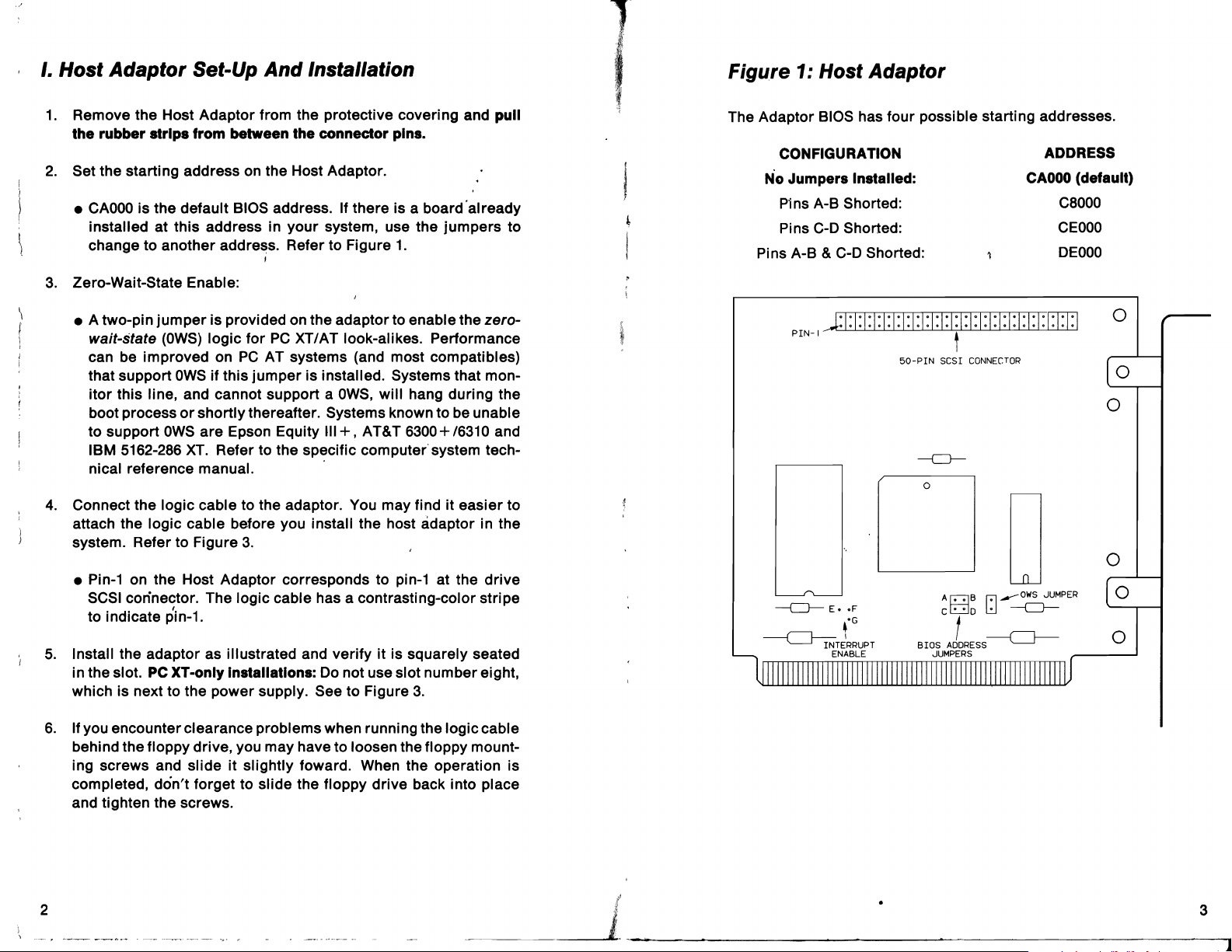
Figure 1: Host Adaptor
The Adaptor BIOS has four possible starting addresses.
CONFIGURATION
N'o
Jumpers Installed:
P1ns
A-B Shorted:
Pins
C-D
Shorted:
Pins A-B &
C-O
Shorted:
ADDRESS
CAOOO
C8000
CEOOO
DEOOO
(default)
• A two-pin
wait-state
can be improved on
that support
itor
boot process
to support
IBM 5162-286
nical reference manual. .
4.
Connect the logic cable to the adaptor. You may find it easier to
attach the logic cable before you install the host adaptor in the
system. Refer to Figure
• Pin-1 on the Host Adaptor corresponds to pin-1 at the
SCSI connector. The logic cable has a contrasting-color stripe
to indicate pin-1.
5.
Install the adaptor as illustrated and verify
in the slot.
which is next to the power supply. See to Figure
6.
If you encounter clearance problems when running the logic cable
behind the floppy drive, you may have to loosen the floppy mount-
ing screws and slide it slightly foward. When the operation is
completed, don't forget to slide the floppy drive back into place
and tighten the screws.
jumper
(OWS)
this line, and cannot support a
is provided on the adaptor to enable the zero-
logic
for
PC
XT/AT look-alikes. Performance
PC
AT systems (and most compatibles)
OWS
if this
jumper
or
shortly thereafter. Systems known to be unable
OWS
are
Epson Equity
XT.
Refer to the specific computer system tech-
3.
is installed. Systems that mon-
,
PC
XT-only Installations:
Do
OWS,
will hang during the
111+,
AT&T 6300+/6310 and
it
is squarely seated
not use slot number eight,
3.
drive
t
j;:
I:
1:1
:1:1:
.F
'G
1:1:
50-PIN
PIN-i t
---CJ---
E.
,
~TERRUPT
ENABLE
1:1:1: I:1
:1:1:1:
SCSI
CONNECTOR
---CJ---
o
A
c;:::;]B
C
c;:::;]o
f
BIOS
AODRESS----c===J----
JUMPERS
I: I:
1:1:1:1
:r+hJ
o
oWS
lol_
~
---CJ---
JUMPER
o
o
o
o
o
o
2
_~~_~
• 3
1

~
II. Drive Configuration And Installation
•
Do
not unpack a
• Always rest the
hard surface.
• Refer to Figure 3 during installation.
1.
Remove the top cover from your system. Retain the screws.
2.
Set the
SCSI
Adaptor recognizes devices by
• If you are installing one drive, the
• A second physical drive must be set as
jumper
3.
Drive Resistor Termination Packs: If you are installing a single
drive; the resistor termination packs must remain installed. If you
are installing two drives, remove the resistor termination packs
from the first drive.
When installing the resistor termination packs, note that pin-1 is
designated by a dot
the
PCB
drive
until you are ready to install
drive
on
an
anti-static pad; never on an unprotected
t
10
address on the drive. Refer to Figure
their
provided.
or
number one on the pack. A square pad on
indicates pin-1 at the socket. '
it
into a system.
2.
The
SCSI
10
number.
10
number is 0 (no jumper).
10
number
1.
Use the
Host
..
-;:
8.
PC
...
AT, Compaq Oeskpro
require mounting rails. The rails fasten directly to the
ing feet and allow
• For
PC
AT installations, use the narrow mounting rails (note
it
right rail is part number
4,
6-32
and
x 3/16-inch panhead screws as supplied.
• For Compaq Oeskpro
286
and Epson
Equity'"
+ installations
to slide into the system chassis.
50324-001
286,
use the wide mounting rails and
and left rail is 50324-002)
drive
mount-.
4,
6-32 x 5/16-inch flathead screws as supplied. Note that one rail
has tapped holes to allow fastening to the chassis. Use two of
the
6-32
.'
x.3/16-inch"panhead screws to secure the drive to the
chassis side.
~
Epson Equity
'"
+ and AT&T 6310 systems have rails included
with the system. Use these instead of the rails provided .
9.
Attach the logic cable assembly to the drive and Host Adaptor.
Pin-1 at the drive must mate with pin-1 at the adaptor. The logic
cable has a contrasting-color stripe which indicates pin-1. It also
has an additional connector at the drive-end to accommodate a
second hard disc drive.
10.
Drive DC Power Connection:
• Use the straight power cable assembly (refer to Figure
3)
for
Compaq installations. .
4.
Drive mounting Is system dependent. Rails cannot be installed
a front panel is in place. Remove before installing the rails.
5.
Drives are shipped with a half-height, front panel. Determine if
you need to replace it with the full-height panel. Use the same
screws to reinstall the new panel.
6.
PC
AT installations require a printed circuit cable
(PCC)
instead of a front panel. The shield protects the printed circuit
cable. I nstall as illustrated in Figure 3 usi ng the front panel screws.
7.
IBM
PC
XT
and AT&T
6300
installations require
4,
6-32
x 3/16-inch
pan head screws (packed with the rails). Tighten the screws down
evenlyt08
Use only the supplied screws
±.8inch-lbs. Overtightening may cause drive damage.
or
a Seagate-approved equivalent.
4
__
shield
if
~
__
..l_
• Use the Ny" power cable assembly (refer to Figure
and AT&T
~_._-
6310
installations, if two drives are being installed.
.J'.
3)
for
PC
XT
5
-,
 Loading...