

Seagate ST2000VX000,ST1000VX000,ST3000VX000 Product Manual
Product Manual
SV35 Series SATA
ST3500641SV
ST3250824SV
ST3160812SV
100415208
Rev . B
August 2007

Copyright © 2006-2007 Seagate Technology LLC. All rights reserved. Printed in USA
Publication number: 100415208, Rev. B
August 2007
Seagate, Seagate Technology and the Wave logo are registered trademarks of Seagate Technology LLC
in the United States and/or other countries. SV35 Series, SeaTools and SeaTDD are either trademarks or
registered trademarks of Seagate Technology LLC or one of its affiliated companies in the United States
and/or other countries. All other trademarks or registered trademarks are the property of their respective
owners.
One gigabyte, or GB, equals one billion bytes when referring to hard drive capacity. Accessible capacity
may vary depending on oper ating envi ronme nt and for matting. Seagate reserves the right to chan ge, wi thout notice, product offerings or specifications.

SV35 Series SATA Product Manual, Rev. B
i
Contents
1.0 Introduction. . . . . . . . . . . . . . . . . . . . . . . . . . . . . . . . . . . . . . . . . . . . . . . . . . . . . . . . . . . . . . . . . . . 1
1.1 About the Serial ATA interface . . . . . . . . . . . . . . . . . . . . . . . . . . . . . . . . . . . . . . . . . . . . . . 2
2.0 Drive specifications . . . . . . . . . . . . . . . . . . . . . . . . . . . . . . . . . . . . . . . . . . . . . . . . . . . . . . . . . . . . 3
2.1 Specification summaries . . . . . . . . . . . . . . . . . . . . . . . . . . . . . . . . . . . . . . . . . . . . . . . . . . . 3
2.2 Formatted capacity . . . . . . . . . . . . . . . . . . . . . . . . . . . . . . . . . . . . . . . . . . . . . . . . . . . . . 10
2.2.1 LBA mode . . . . . . . . . . . . . . . . . . . . . . . . . . . . . . . . . . . . . . . . . . . . . . . . . . . . . 10
2.3 Default logical geometry . . . . . . . . . . . . . . . . . . . . . . . . . . . . . . . . . . . . . . . . . . . . . . . . . . 10
2.4 Recording and interface technology . . . . . . . . . . . . . . . . . . . . . . . . . . . . . . . . . . . . . . . . . 11
2.5 Physical characteristics . . . . . . . . . . . . . . . . . . . . . . . . . . . . . . . . . . . . . . . . . . . . . . . . . . 12
2.6 Seek time. . . . . . . . . . . . . . . . . . . . . . . . . . . . . . . . . . . . . . . . . . . . . . . . . . . . . . . . . . . . . . 12
2.7 Start/stop times . . . . . . . . . . . . . . . . . . . . . . . . . . . . . . . . . . . . . . . . . . . . . . . . . . . . . . . . . 13
2.8 Power specifications . . . . . . . . . . . . . . . . . . . . . . . . . . . . . . . . . . . . . . . . . . . . . . . . . . . . . 13
2.8.1 Power consumption . . . . . . . . . . . . . . . . . . . . . . . . . . . . . . . . . . . . . . . . . . . . . . 13
2.8.2 Conducted noise . . . . . . . . . . . . . . . . . . . . . . . . . . . . . . . . . . . . . . . . . . . . . . . . 15
2.8.3 Voltage tolerance. . . . . . . . . . . . . . . . . . . . . . . . . . . . . . . . . . . . . . . . . . . . . . . . 15
2.8.4 Power-management modes. . . . . . . . . . . . . . . . . . . . . . . . . . . . . . . . . . . . . . . . 15
2.9 Environmental specifications. . . . . . . . . . . . . . . . . . . . . . . . . . . . . . . . . . . . . . . . . . . . . . . 16
2.9.1 Ambient temperature . . . . . . . . . . . . . . . . . . . . . . . . . . . . . . . . . . . . . . . . . . . . . 16
2.9.2 Temperature gradient. . . . . . . . . . . . . . . . . . . . . . . . . . . . . . . . . . . . . . . . . . . . . 16
2.9.3 Humidity. . . . . . . . . . . . . . . . . . . . . . . . . . . . . . . . . . . . . . . . . . . . . . . . . . . . . . . 16
2.9.4 Altitude. . . . . . . . . . . . . . . . . . . . . . . . . . . . . . . . . . . . . . . . . . . . . . . . . . . . . . . . 16
2.9.5 Shock. . . . . . . . . . . . . . . . . . . . . . . . . . . . . . . . . . . . . . . . . . . . . . . . . . . . . . . . . 17
2.9.6 Vibration. . . . . . . . . . . . . . . . . . . . . . . . . . . . . . . . . . . . . . . . . . . . . . . . . . . . . . . 17
2.10 Acoustics. . . . . . . . . . . . . . . . . . . . . . . . . . . . . . . . . . . . . . . . . . . . . . . . . . . . . . . . . . . . . . 18
2.11 Electromagnetic immunity . . . . . . . . . . . . . . . . . . . . . . . . . . . . . . . . . . . . . . . . . . . . . . . . . 18
2.12 Reliability. . . . . . . . . . . . . . . . . . . . . . . . . . . . . . . . . . . . . . . . . . . . . . . . . . . . . . . . . . . . . . 19
2.13 Agency certification . . . . . . . . . . . . . . . . . . . . . . . . . . . . . . . . . . . . . . . . . . . . . . . . . . . . . . 19
2.13.1 Safety certification . . . . . . . . . . . . . . . . . . . . . . . . . . . . . . . . . . . . . . . . . . . . . . . 19
2.13.2 Electromagnetic compatibility. . . . . . . . . . . . . . . . . . . . . . . . . . . . . . . . . . . . . . . 19
2.13.3 FCC verification . . . . . . . . . . . . . . . . . . . . . . . . . . . . . . . . . . . . . . . . . . . . . . . . . 20
2.14 Environmental protection. . . . . . . . . . . . . . . . . . . . . . . . . . . . . . . . . . . . . . . . . . . . . . . . . . 21
2.14.1 European Union Restriction of Hazardous Substances (RoHS) . . . . . . . . . . . . 21
2.15 Corrosive environment . . . . . . . . . . . . . . . . . . . . . . . . . . . . . . . . . . . . . . . . . . . . . . . . . . . 21
3.0 Configuring and mounting the drive . . . . . . . . . . . . . . . . . . . . . . . . . . . . . . . . . . . . . . . . . . . . . 23
3.1 Handling and static-discharge precautions . . . . . . . . . . . . . . . . . . . . . . . . . . . . . . . . . . . . 23
3.2 Breather filter hole precautions . . . . . . . . . . . . . . . . . . . . . . . . . . . . . . . . . . . . . . . . . . . . . 24
3.3 Configuring the drive . . . . . . . . . . . . . . . . . . . . . . . . . . . . . . . . . . . . . . . . . . . . . . . . . . . . . 25
3.4 Serial ATA cables and connectors . . . . . . . . . . . . . . . . . . . . . . . . . . . . . . . . . . . . . . . . . . 25
3.5 Drive mounting . . . . . . . . . . . . . . . . . . . . . . . . . . . . . . . . . . . . . . . . . . . . . . . . . . . . . . . . . 26
4.0 Serial ATA (SATA) interface . . . . . . . . . . . . . . . . . . . . . . . . . . . . . . . . . . . . . . . . . . . . . . . . . . . . 27
4.1 Hot-Plug compatibility . . . . . . . . . . . . . . . . . . . . . . . . . . . . . . . . . . . . . . . . . . . . . . . . . . . . 27
4.2 Serial ATA device plug connector pin definitions. . . . . . . . . . . . . . . . . . . . . . . . . . . . . . . . 28
4.3 Supported ATA commands . . . . . . . . . . . . . . . . . . . . . . . . . . . . . . . . . . . . . . . . . . . . . . . . 30
4.3.1 Identify Device command. . . . . . . . . . . . . . . . . . . . . . . . . . . . . . . . . . . . . . . . . . 33
4.3.2 Set Features command . . . . . . . . . . . . . . . . . . . . . . . . . . . . . . . . . . . . . . . . . . . 37
4.3.3 S.M.A.R.T. commands. . . . . . . . . . . . . . . . . . . . . . . . . . . . . . . . . . . . . . . . . . . . 38
4.3.4 Streaming feature set support . . . . . . . . . . . . . . . . . . . . . . . . . . . . . . . . . . . . . . 39
5.0 Seagate Technology support services. . . . . . . . . . . . . . . . . . . . . . . . . . . . . . . . . . . . . . . . . . . . 49

ii
SV35 Series SATA Product Manual, Rev . B

SV35 Series SATA Product Manual, Rev. B
iii
List of Figures
Figure 1. Typical 5V startup and operation current profile. . . . . . . . . . . . . . . . . . . . . . . . . . . . . . . . . . . 14
Figure 2. Typical 12V startup and operation current profile. . . . . . . . . . . . . . . . . . . . . . . . . . . . . . . . . . 14
Figure 3. Breather filter hole location. . . . . . . . . . . . . . . . . . . . . . . . . . . . . . . . . . . . . . . . . . . . . . . . . . . 24
Figure 4. Serial ATA jumper block and connectors . . . . . . . . . . . . . . . . . . . . . . . . . . . . . . . . . . . . . . . . 25
Figure 5. Attaching SATA cabling . . . . . . . . . . . . . . . . . . . . . . . . . . . . . . . . . . . . . . . . . . . . . . . . . . . . . 25
Figure 6. Mounting dimensions—top, side and end view . . . . . . . . . . . . . . . . . . . . . . . . . . . . . . . . . . . 26


SV35 Series SATA Product Manual, Rev. B
1
1.0 Introduction
This manual describes the functional, mechanical and interface specifications for the following Seagate
SV35 Series SATA model drives:
• ST3500641SV
• ST3250824SV
• ST3160812SV
These drives provide the following key features:
• Specifically designed for surveilance DVRs.
• Optimized power for surveillance systems--spinup limited to a maximum to 2.0 amps.
• Seek profile optimized for surveillance performance and power consumption.
• 7,200 RPM spindle speed.
• 16 Mbyte buffer: ST3500641SV.
• 8 Mbyte buffer: ST3250824SV and ST3160812SV
• High instantaneous (burst) data-transfer rates (up to 300 Mbytes per second).
• Tunneling Magnetoresistive (TMR) recording heads.
• Native Command Queueing with command ordering to increase performance in demanding applications.
• State-of-the-art cache and on-the-fly error-correction algorithms.
• Full-track multiple-sector transfer capability without local processor intervention.
• 350 Gs nonoperating shock.
• Support for S.M.A.R.T. drive monitoring and reporting.
• Support for Read Multiple and Write Multiple commands.
• SeaTools diagnostic software performs a drive self-test that eliminates unnecessary drive returns.
• Supports latching SATA cables and connectors.
• The 3D Defense System™, which includes Drive Defense, Data Defense, and Diagnostic Defense, offers
the industry’s most comprehensive protection for disc drives.

2
SV35 Series SATA Product Manual, Rev . B
1.1 About the Serial A TA interface
The Serial ATA interface provides several advantages over the traditional (parallel) ATA interface. The primary
advantages include:
• Easy installation and configuration with true plug-and-play connectivity. It is not necessary to set any jumpers or other configuration options.
• Thinner and more flexible cabling for improved enclosure airflow and ease of installation.
• Scalability to higher performance levels.
In addition, Serial ATA makes the transiti o n from pa rallel ATA eas y by providing legacy software suppo rt. Seri al
ATA was designed to allow you to install a Serial ATA host adapter and Serial ATA disc drive in your current
system and expect all of your existing applications to work as normal.
The Serial ATA interface connects each disc drive in a point-to-point configuration with the Serial ATA host
adapter. There is no master/slave relationship with Serial ATA devices like there is with parallel ATA. If two
drives are attached on one Serial ATA host adapter, the host operatin g system views the two devices as if they
were both “masters” on two separate ports. This essentially means both drives behave as if they are Device 0
(master) devices.
Note. The host adapter may, optionally, emulate a master/slave environment to host software where two
devices on separate Serial ATA ports are represented to host software as a Device 0 (master) and
Device 1 (slave) accessed at the same set of host bus addresses. A host adapter that emulates a
master/slave environment manages two sets of shadow registers. This is not a typical Serial ATA
environment.
The Serial ATA host adapter and drive share the function of emulating parallel ATA device behavior to provide
backward compatibility with existing host systems and software. The Command and Control Block registers,
PIO and DMA data transfers, resets, and interrupts are all emulated.
The Serial ATA host adapter cont ains a set of regi ste rs that sha dow the conte nt s of t he trad itional device r egis ters, referred to as the Shadow Register Block. All Serial ATA devices behave like Device 0 devices. For additional information about how Serial ATA emulates parallel ATA, refer to the “Serial ATA: High Speed Serialized
AT Attachment” specification. The specification can be downloaded from www.serialata.org.

SV35 Series SATA Product Manual, Rev. B
3
2.0 Drive specifications
Unless otherwise noted, all specifications are measured under ambient conditions, at 25°C, and nominal
power. For convenience, the phrases the drive and this drive are used throughout this manual to indicate the
following models:
ST3500641SV
ST3250824SV
ST3160812SV
2.1 Specification summaries
The specifications listed in tables 1 and 2 are for quick reference. For details on specification measurement or
definition, see the appropriate section of this manual.

4
SV35 Series SATA Product Manual, Rev . B
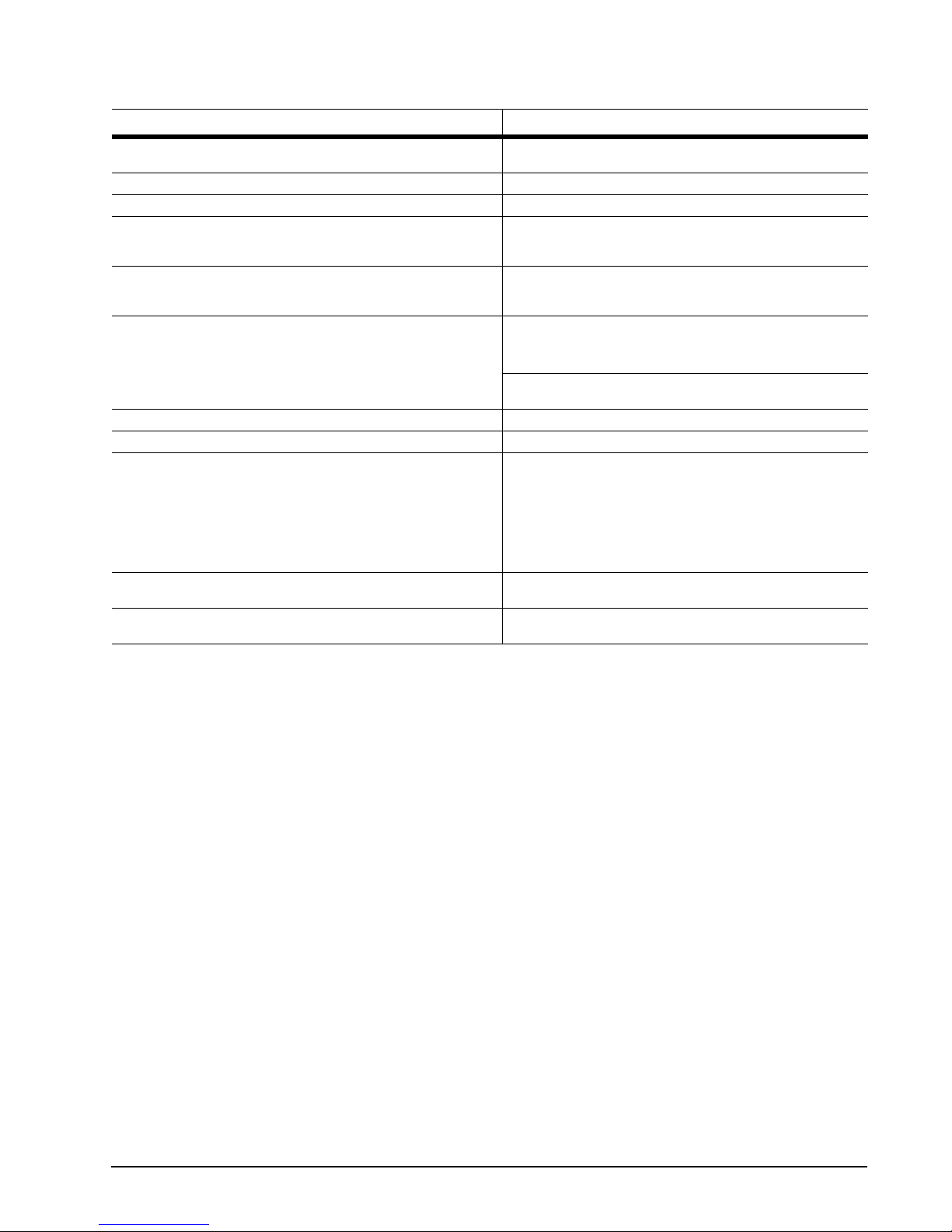
Table 1: Drive specifications for 500 Gbyte models
Drive specification ST3500641SV
Formatted Gbytes (512 bytes/sector)* 500
Guaranteed sectors 976,773,168
Bytes per sector 512
Default sectors per track 63
Default read/write heads 16
Default cylinders 16,383
Recording density in BPI (kbits/inch max) 790.1
Track density TPI (ktracks/inch avg) 124.5
Areal density (Gbits/inch2 avg) 97.96
Spindle speed (RPM) 7,200
Internal data transfer rate (Mbits/sec max) 815.2
Sustained transfer rate (Mbytes/sec max) 65
I/O data transfer rate (Mbytes/sec max) 300
ATA data-transfer modes supported PIO modes 0–4
SATA data-transfer modes supported 3.0 Gbits/sec
Cach e buffer 8 Mbytes
Height (max) 26.1 mm (1.028 inches)
Width (max) 101.6 mm (4.000 inches) +/-0.010 inches
Length (max) 146.99 mm (5.787 inches)
Weight (max) grams 710 grams
Average latency (msec) 4.16
Power-on to ready (max) 16 sec
Standby to ready (max) 16 sec
Track-to-track seek time (msec typical) <0.8 (read), <1.0 (write)
Average seek (msec typical) 18 (read), 20 (write)
Startup current (typical) 12V (peak) 2.0 amps
Seek power (typical) 8.6 watts
DVR Operating (typical) 8.45 watts
Idle mode (typical) 8.00 watts
Standby mode (typical) 0.80 watts
Sleep mode (typical) 0.80 watts
Voltage tolerance
(including noise)
Ambient temperature 0° to 60°C (operating)
Temperature gradient
(°C per hour max)
Relative humidity 5% to 90% (operating)
Relative humidity gradient 30% per hour max
Wet bulb temperature
(°C max)
Altitude, operating –60.96 m to 3,048 m
Multiword DMA modes 0–2
Ultra DMA modes 0–6
1.5 Gbits/sec
5V ± 5%
12V ± 10%
–40° to 70°C (nonoperating)
20°C (operating)
30°C (nonoperating)
5% to 95% (nonoperating)
37.7 (operating)
40.0 (nonoperating)
(–200 ft to 10,000+ ft)
SV35 Series SATA Product Manual, Rev. B
5
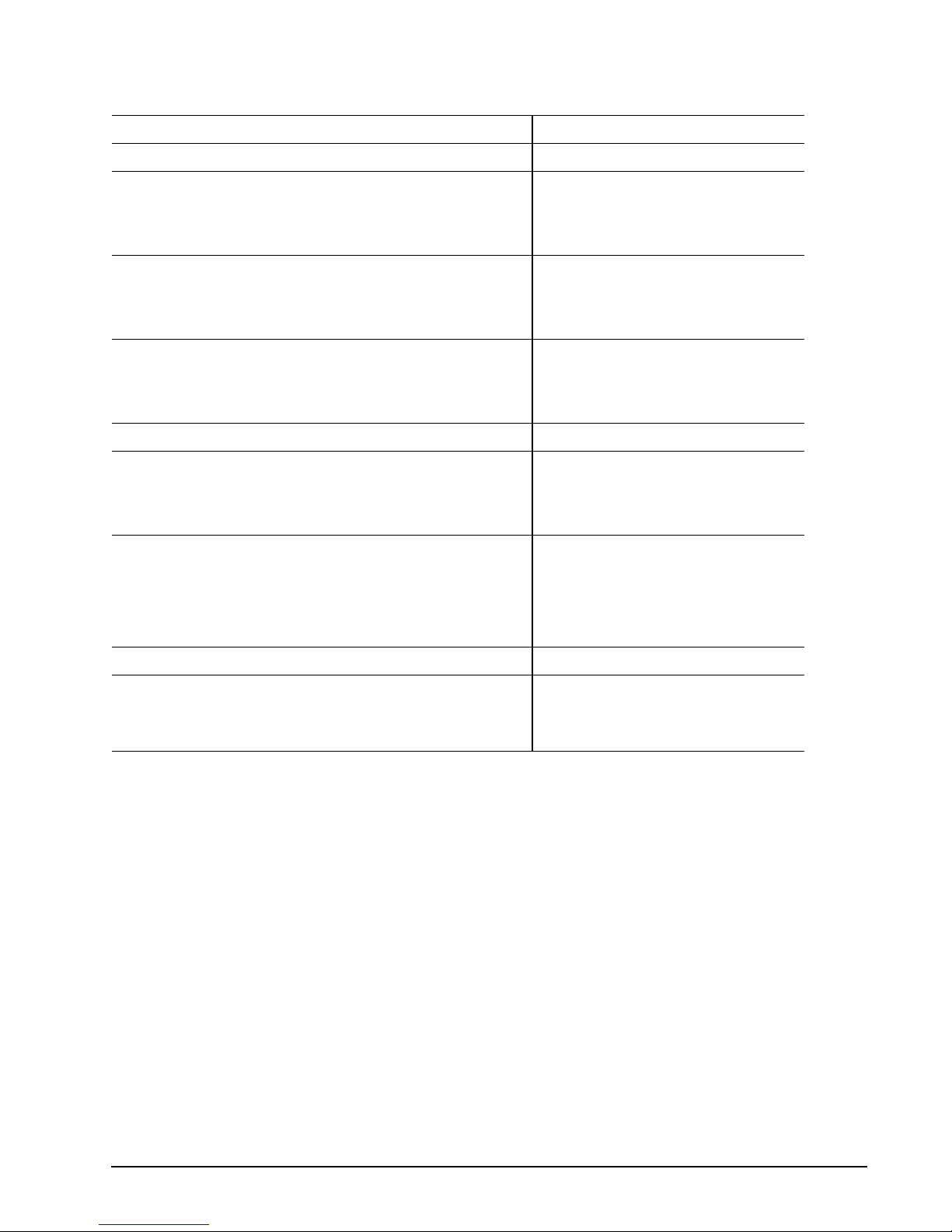
Table 1: Drive specifications for 500 Gbyte models
Drive specification ST3500641SV
Altitude, nonoperating
(meters below mean sea level, max)
Shock, operating (max at 2 msec) 63 Gs
Shock, nonoperating (max at 2 msec) 300 Gs
Vibration, operating 5-22 Hz: +/-0.25”, Displacement limited
Vibration, nonoperating 5-22 Hz: +/-0.25”, Displacement limited
Drive acoustics, sound power
Idle** (bels) 2.79 (typical)
Operational, DVR seeks (bels) 2.71 (typical)
Nonrecoverable read errors 1 per 10
Annualized Failure Rate (AFR) <1%
Warranty 5 years on distribution units.
Contact start-stop cycles
(25°C, 50% relative humidity)
Supports Hotplug operation per SATA II
specification
–60.96 m to 12,192 m
(–200 ft to 40,000+ ft)
22-350 Hz: 0.5 Gs
350-500 Hz: 0.25 Gs
23-350 Hz: 5.0 Gs
351-500 Hz: 1.0 Gs
2.96 (max)
2.88 (max)
14
bits read
To determine the warranty for a specific drive, use a web
browser to access the following web page:
www.seagate.com/support/service/
From this page, click on the “Verify Your Warranty” link. You will
be asked to provide the drive serial number, model number (or
part number) and country of purchase. The system will display
the warranty information for your drive.
50,000
Yes
*One Gbyte equals one billion bytes when referring to hard drive capacity. Accessible capacity may vary depending on operating environment
and formatting.
**Dur ing per io ds of driv e idle, some offline activity may occur accor di ng to the S.M.A.R. T . speci ficati on , whi ch may i ncrea se ac oustic an d
power to operational levels..

6
SV35 Series SATA Product Manual, Rev . B
Table 2: Drive specifications for 250 Gbyte models
Drive specification ST3250824SV
Formatted Gbytes (512 bytes/sector)* 250
Guaranteed sectors 488,397,168
Bytes per sector 512
Default sectors per track 63
Default read/write heads 16
Default cylinders 16,383
Recording density in BPI (kbits/inch max) 790.1
Track density TPI (ktracks/inch avg) 124.5
Areal density (Gbits/inch2 avg) 97.69
Spindle speed (RPM) 7,200
Internal data transfer rate (Mbits/sec max) 867.2
Sustained transfer rate (Mbytes/sec max) 76.6
I/O data transfer rate (Mbytes/sec max) 300
ATA data-transfer modes supported PIO modes 0–4
SATA data-transfer modes supported 3.0 Gbits/sec
Cach e buffer 8 Mbytes
Height (max) 26.1 mm (1.028 inches)
Width (max) 101.6 mm (4.000 inches) +/-0.010 inches
Length (max) 146.99 mm (5.787 inches)
Weight (max) grams 580 grams (1.28 lb.)
Average latency (msec) 4.16
Power-on to ready (typical) 16 sec
Standby to ready (typical) 16 sec
Track-to-track seek time (msec typical) <0.8 (read), <1.0 (write)
Average seek (msec typical) 18 (read), 20 (write)
Startup current (typical) 12V (peak) 2.0 amps
Seek power (typical) 8.6 watts
DVR Operating (typical) 6.49 watts
Idle mode (typical) 8.00 watts
Standby mode (typical) 0.80 watts
Sleep mode (typical) 0.80 watts
Voltage tolerance
(including noise)
Ambient temperature 0° to 60°C (operating)
Temperature gradient
(°C per hour max)
Relative humidity 5% to 90% (operating)
Relative humidity gradient 30% per hour max
Wet bulb temperature
(°C max)
Altitude, operating –60.96 m to 3,048 m
Multiword DMA modes 0–2
Ultra DMA modes 0–6
1.5 Gbits/sec
5V ± 5%
12V ± 10%
–40° to 70°C (nonoperating)
20°C (operating)
30°C (nonoperating)
5% to 95% (nonoperating)
37.7 (operating)
40 (nonoperating)
(–200 ft to 10,000+ ft)

SV35 Series SATA Product Manual, Rev. B
7
Table 2: Drive specifications for 250 Gbyte models
Drive specification ST3250824SV
Altitude, nonoperating
(meters below mean sea level, max)
Shock, operating (max at 2 msec) 63 Gs
Shock, nonoperating (max at 2 msec) 350 Gs
Vibration, operating 5-22 Hz: +/-0.25”, Displacement limited
Vibration, nonoperating 5-22 Hz: +/-0.25”, Displacement limited
Drive acoustics, sound power (bels)
Idle** (bels) 2.67 (typical)
Operational, DVR seeks (bels) 2.8 (typical
Nonrecoverable read errors 1 per 10
Annualized Failure Rate (AFR) <1%
Warranty 5 years on distribution units.
Contact start-stop cycles
(25°C, 50% relative humidity)
Supports Hotplug operation per SATA II specification Yes
–60.96 m to 12,192 m
(–200 ft to 40,000+ ft)
22-350 Hz: 0.5 Gs
350-500 Hz: 0.25 Gs
22-350 Hz: 5.0 Gs
350-500 Hz: 1.0 Gs
2.82 (max)
2.9 (max)
14
bits read
T o determine the warranty for a specific drive, use a web browser to access
the following web page:
www.seagate.com/support/service/
From this page, click on the “Verify Your Warranty” link. You will be asked to
provide the drive serial number, model number (or part number) and country of purchase. The system will display the warranty information for your
drive.
50,000
*One Gbyte equals one billion bytes when referring to hard drive capacity. Accessible capacity may vary depending on operating environment
and formatting.
**Dur ing per io ds of driv e idle, some offline activity may occur accor di ng to the S.M.A.R. T . speci ficati on , whi ch may i ncrea se ac oustic an d
power to operational levels.

8
SV35 Series SATA Product Manual, Rev . B
Table 3: Drive specifications for 160 Gbyte models
Drive specification ST3160212SCE
Formatted Gbytes (512 bytes/sector)* 160
Guaranteed sectors 312,581,808
Bytes per sector 512
Default sectors per track 63
Default read/write heads 16
Default cylinders 16,383
Recording density in BPI (kbits/inch max) 840.0
Track density TPI (ktracks/inch avg) 141.5
Areal density (Gbits/inch2 avg) 119.0
Spindle speed (RPM) 7,200
Internal data transfer rate (Mbits/sec max) 867.2
Sustained transfer rate (Mbytes/sec max) 83.0
I/O data transfer rate (Mbytes/sec max) 300
ATA data-transfer modes supported PIO modes 0–4
SATA data-transfer modes supported 1.5 Gbits/sec
Cach e buffer 2 Mbytes
Height (max) 26.1 mm (1.028 inches)
Width (max) 101.6 mm (4.000 inches) +/-0.010 inches
Length (max) 146.99 mm (5.787 inches)
Weight (typical) 580 grams (1.28 lb.)
Average latency (msec) 4.16
Power-on to ready (typical) 16 secs
Standby to ready (typical) 16 secs
Track-to-track seek time (msec typical) <0.8 (read), <1.0 (write)
Average seek (msec typical) 18 (read), 20 (write)
Startup current (typical) 12V (peak) 2.0 amps
Seek power (typical) 8.6 watts
DVR Operating (typical) 5.71 watts
Idle mode (typical) 8.00 watts
Standby mode (typical) 0.80 watts
Sleep mode (typical) 0.80 watts
Voltage tolerance
(including noise)
Ambient temperature 0° to 60°C (operating)
Temperature gradient
(°C per hour max)
Relative humidity 5% to 90% (operating)
Relative humidity gradient 30% per hour max
Wet bulb temperature
(°C max)
Altitude, operating –60.96 m to 3,048 m
Multiword DMA modes 0–2
Ultra DMA modes 0–6
3.0 Gbits/sec
5V ± 5%
12V ± 10%
–40° to 70°C (nonoperating)
20°C (operating)
30°C (nonoperating)
5% to 95% (nonoperating)
37.7 (operating)
40 (nonoperating)
(–200 ft to 10,000+ ft)

SV35 Series SATA Product Manual, Rev. B
9
Table 3: Drive specifications for 160 Gbyte models
Drive specification ST3160212SCE
Altitude, nonoperating
(meters below mean sea level, max)
Shock, operating (max at 2 msec) 63 Gs
Shock, nonoperating (max at 2 msec) 350 Gs
Vibration, operating 5-22 Hz: 0.25 Gs, Limited displacement
Vibration, nonoperating 5-22 Hz: 0.25 Gs, Limited displacement
Drive acoustics, sound power (bels)
Idle** (bels) 2.48 (typical)
Operational, DVR seeks (bels) 2.53 (typical)
Nonrecoverable read errors 1 per 10
Annualized Failure Rate (AFR) <1%
Warranty 5 years on distribution units.
Contact start-stop cycles
(25°C, 50% relative humidity)
Supports Hotplug operation per SATA II
specification
–60.96 m to 12,192 m
(–200 ft to 40,000+ ft)
22-350 Hz: 0 .5 Gs
350-500 Hz: 0.25 Gs
23-350 Hz: 5 .0 Gs
351-500 Hz: 1.0 Gs
2.64 (max)
2.62 (max)
14
bits read
To determine the warranty for a specific drive, use a web browser to
access the following web page:
www.seagate.com/support/service/
From this page, click on the “Verify Your Warranty” link. You will be
asked to provide the drive serial number, model number (or part number) and country of purchase. The system will display the warranty information for your drive.
50,000
Yes
*One Gbyte equals one billion bytes when referring to hard drive capacity. Accessible capacity may vary depending on operating environment
and formatting.
**During period s of driv e idle, some offline activity may occu r ac cor ding to th e S. M.A .R.T. s pe cif icati on, whi ch ma y in crease acoustic and
power to operational levels.

10
SV35 Series SATA Product Manual, Rev . B
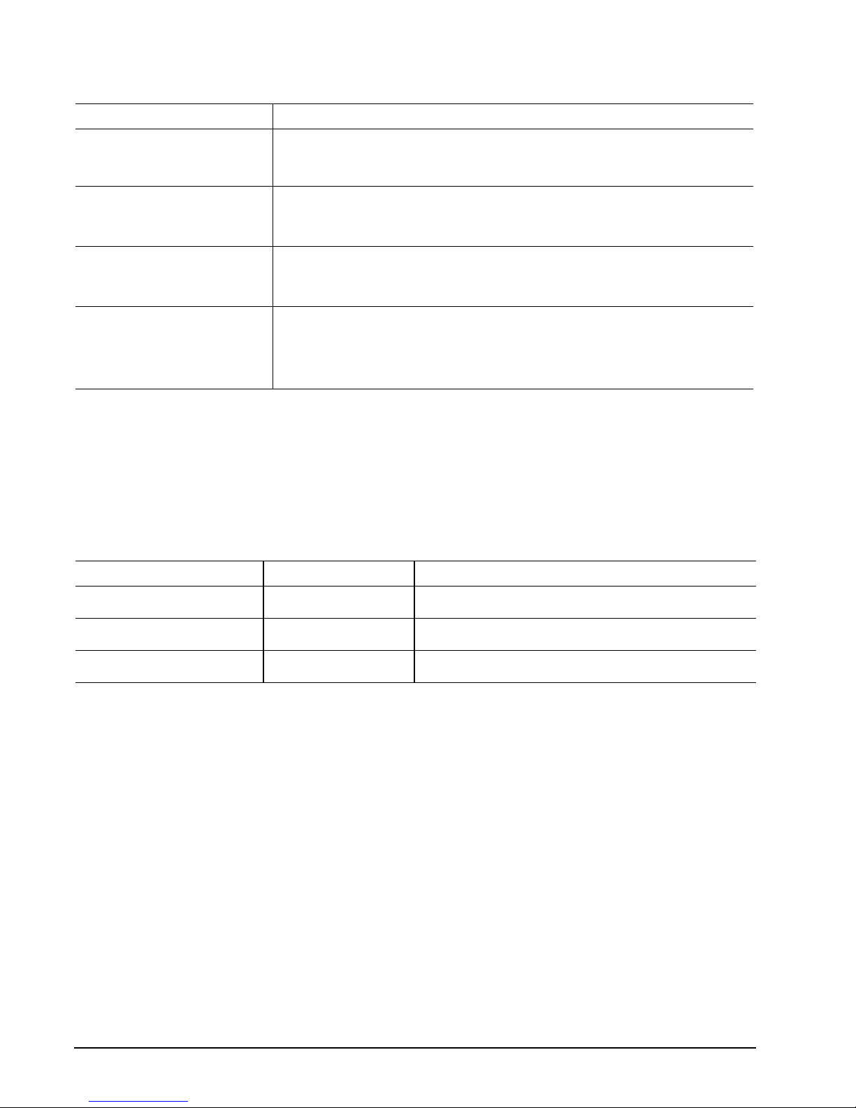
2.2 Formatted ca pacity
Model Formatted capacity* Guaranteed sectors Bytes per sector
ST3500641SV 500 Gbytes 976,773,168 512
ST3250824SV 250 Gbytes 488,397,168 512
ST3160812SV 160 Gbytes 312,581,808 512
*One Gbyte equals one billion bytes when referring to hard drive capacity. Accessible capacity may vary depending on operating environment
and formatting.
2.2.1 LBA mode
When addressing these drives in LBA mode, all blocks (sectors) are consecutively numbered from 0 to n–1,
where n is the number of guaranteed sectors as defined above.
See Section 4.3.1, "Identify Device command" (words 60-61 and 100-103) for additional information about 48bit addressing support of drives with capacities over 137 Gbytes.
2.3 Default logi cal geometr y
Cylinders Read/write heads Sectors per track
16,383 16 63
LBA mode
When addressing these drives in LBA mode, all blocks (sectors) are consecutively numbered from 0 to n–1,
where n is the number of guaranteed sectors as defined above.
SV35 Series SATA Product Manual, Rev. B
11
2.4 Recording and interfac e te ch no l o gy
Interface ATA
Recording method 16/17 EPRML
Recording density KBPI (kbits/inch max)
ST3500641SV and ST3250824SV 790.1
ST3160812SV 840.0
Track density KTPI (ktracks/inch max)
ST3500641SV and ST3250824SV 124.5
ST3160812SV 141.5
Areal density (Gbits/inch2 max)
ST3500641SV and ST3250824SV 97.69
ST3160812SV 119.0
Spindle speed (RPM) (± 0.2%) 7,200
Internal data-transfer rate (Mbits/sec max)
ST3500641SV and ST3250824SV 815.2
ST3160812SV 867.2
Sustained data transfer rate (Mbytes/sec max)
ST3500641SV 65.0
ST3250824SV 76.6
ST3160812SV 83.0
I/O data-transfer rate (Mbytes/sec max) 300
Cache buffer
ST3500641SV
ST3250824SV and ST3160812SV
16 Mbytes (16,385 kbytes)
8 Mbytes (8,192 kbytes)
12
SV35 Series SATA Product Manual, Rev . B
2.5 Physical characteristics
Drive specification
Maximum he i g ht
(mm)
(inches)
26.1
1.028
Maximum wid th
(mm)
(inches)
Maximum length
(mm)
(inches)
Maximum wei g h t
ST3500641SV
ST3250824SV
ST3160812SV
101.6
4.000 +/- 0.010
146.99
5.787
710 grams (1.57 lbs)
580 grams (1.28 lbs)
2.6 Seek time
Seek measurem ent s a re t ake n wi th nom inal po w er a t 25 °C amb ient temperature. All tim es a re m easu red using
drive diagnostics. The specifications in the table below are defined as follows:
• Track-to-track seek time is an average of all possible single-track seeks in both directions.
• Average seek time is a true statistical random average of at least 5,000 measurements of seeks between
random tracks, less overhead.
T yp ical seek times (msec) Read Write
Track-to-track 0.8 1.0
Average 18 20
Average latency: 4.16 4.16
Note. These drives ar e de si gned to consisten tl y me et t he se ek t imes r epr esente d in thi s manu al. P hysical
seeks, regardless of mode (such as track-to-track and average), are expected to meet or exceed
the noted values. However, due to the manner in which these drives are formatted, benchmark
tests that include command overhead or measure logical seeks may produce results that vary from
these specifications.

SV35 Series SATA Product Manual, Rev. B
13
2.7 Start/stop times
Power-on to Ready (sec) 16
St andby to Ready (sec) 16 (max)
Ready to spindle stop (sec) 10 (max)
2.8 Power specifications
The drive receives DC power (+5V and +12V) through a native SATA power connector. See Figure 5 on
page 25.
2.8.1 Power consumption
Power requiremen ts fo r the drive s are listed i n the t able on pa ge 9. Typical power measurements are based on
an average of drives tested, under nominal conditions, using 5.0V and 12.0V input voltage at 25°C ambient
temperature.
• Spinup power
Spinup power is measured from the time of power-on to the time that the drive spindle reaches operating
speed.
• Seek mode
During seek mode, the read/write actuator arm moves toward a specific position on the disc surface and
does not execute a read or write operation. Servo electronics are active. Seek mode power represents the
worst-case power consumption, using only random seeks with read or write latency time. This mode is not
typical and is provided for worst-case information.
• Operating power and current
Operating power is measured using a standard Surveillance Storage Profile.
• Idle mode power
Idle mode power is measu red with the drive up to speed, with servo e le ctron ics acti ve and with the he ads i n
a random track location.
• Standby mode
During Standby mode, the drive accepts commands, but the drive is not spinning, and the servo and read/
write electronics are in power-down mode.
 Loading...