

ST2000NX0243,ST1000NX0303,ST2000NX0253,ST1000NX0313,ST2000NX0403,ST1000NX0423,ST2000NX0283,ST1000NX0343,ST2000NX0303,ST1000NX0353
Seagate ST2000NX0243,ST1000NX0303,ST2000NX0253,ST1000NX0313,ST2000NX0403,ST1000NX0423,ST2000NX0283,ST1000NX0343,ST2000NX0303,ST1000NX0353 Product Manual

Enterprise
Capacity 2.5 HDD
SATA Product Manual
4096
Native
512
Emulation
512
Native
Standard
models
ST2000NX0243
ST1000NX0303
ST2000NX0253
ST1000NX0313
ST2000NX0403
ST1000NX0423
Self-Encrypting
models
ST2000NX0283
ST1000NX0343
ST2000NX0303
ST1000NX0353
100715314, Rev. D
July 2015

Document Revision History
Revision Date Description of changes
Rev . A 08/08/2014 Initial release.
Rev. B 01/29/2015
Rev. C 02/09/2015 Pages - 9 & 20: Corrected AFR value to 0.44%
Rev. D 07/06/2015
Pages - fc, bc, 10-11 & 20: Applied new logos, applied new page numbering convention, deleted
Index [no longer required], DC power tables: +5V avg Idle/Idle A current updates, changed MTBF to
2M, changed to "Maximum Rated Workload" & updated Workload text, delete text in Section 2.10.1.
Page FC: Applied new cover design/layout
Pages FC, 6, 8, 10 & 34-35: Added 512N models & specs and 512N as needed.
© 2015 Seagate Technology LLC. All rights reserved.
Publication number: 100715314, Rev. D July 2015
Seagate, Seagate Technology and the Spiral logo are registered trademarks of Seagate Technology LLC in the United States and/or
other countries. PowerChoice and SeaTools are either trademarks or registered trademarks of Seagate Technology LLC or one of its
affiliated companies in the United States and/or other countries. The FIPS logo is a certification mark of NIST, which does not imply
product endorsement by NIST, the U.S., or Canadian governments. All other trademarks or registered trademarks are the property of
their respective owners.
No part of this publication may be reproduced in any form without written permission of Seagate Technology LLC.
Call 877-PUB-TEK1 (877-782-8351) to request permission.
When referring to drive capacity, one gigabyte, or GB, equals one billion bytes and one terabyte, or TB, equals one trillion bytes. Y our
computer’s operating system may use a different standard of measurement and report a lower capacity . In addition, some of the listed
capacity is used for formatting and other functions, and thus will not be available for data storage. Actual quantities will vary based on
various factors, including file size, file format, features and application software. Actual data rates may vary depending on operating
environment and other factors. The export or re-export of hardware or software containing encryption may be regulated by the U.S.
Department of Commerce, Bureau of Industry and Security (for more information, visit
use outside of the U.S. Seagate reserves the right to change, without notice, product offerings or specifications.
www.bis.doc.gov), and controlled for import and

Contents
Seagate® Technology Support Services . . . . . . . . . . . . . . . . . . . . . . . . . . . . . . . . . . . . . . . . . . . . . . . . . 5
1.0 Introduction. . . . . . . . . . . . . . . . . . . . . . . . . . . . . . . . . . . . . . . . . . . . . . . . . . . . . . . . . . . . . . . . . . . 6
1.1 About the Serial ATA interface . . . . . . . . . . . . . . . . . . . . . . . . . . . . . . . . . . . . . . . . . . . . . . 7
2.0 Drive specifications . . . . . . . . . . . . . . . . . . . . . . . . . . . . . . . . . . . . . . . . . . . . . . . . . . . . . . . . . . . . 8
2.1 Specification summary tables . . . . . . . . . . . . . . . . . . . . . . . . . . . . . . . . . . . . . . . . . . . . . . . 8
2.2 Formatted capacity . . . . . . . . . . . . . . . . . . . . . . . . . . . . . . . . . . . . . . . . . . . . . . . . . . . . . . 10
2.2.1 LBA mode . . . . . . . . . . . . . . . . . . . . . . . . . . . . . . . . . . . . . . . . . . . . . . . . . . . . . 10
2.3 Recording and interface technology . . . . . . . . . . . . . . . . . . . . . . . . . . . . . . . . . . . . . . . . . 10
2.4 Start/stop times . . . . . . . . . . . . . . . . . . . . . . . . . . . . . . . . . . . . . . . . . . . . . . . . . . . . . . . . . 10
2.5 Power specifications . . . . . . . . . . . . . . . . . . . . . . . . . . . . . . . . . . . . . . . . . . . . . . . . . . . . . 11
2.5.1 Power consumption . . . . . . . . . . . . . . . . . . . . . . . . . . . . . . . . . . . . . . . . . . . . . . 11
2.5.2 Conducted noise . . . . . . . . . . . . . . . . . . . . . . . . . . . . . . . . . . . . . . . . . . . . . . . . 15
2.5.3 Voltage tolerance . . . . . . . . . . . . . . . . . . . . . . . . . . . . . . . . . . . . . . . . . . . . . . . . 15
2.5.4 Power-management modes. . . . . . . . . . . . . . . . . . . . . . . . . . . . . . . . . . . . . . . . 15
2.5.5 Extended Power Conditions - PowerChoiceTM. . . . . . . . . . . . . . . . . . . . . . . . . 16
2.6 Environmental limits. . . . . . . . . . . . . . . . . . . . . . . . . . . . . . . . . . . . . . . . . . . . . . . . . . . . . . 18
2.6.1 Temperature. . . . . . . . . . . . . . . . . . . . . . . . . . . . . . . . . . . . . . . . . . . . . . . . . . . . 18
2.6.2 Humidity . . . . . . . . . . . . . . . . . . . . . . . . . . . . . . . . . . . . . . . . . . . . . . . . . . . . . . . 18
2.6.3 Effective Altitude (sea level) . . . . . . . . . . . . . . . . . . . . . . . . . . . . . . . . . . . . . . . 18
2.6.4 Shock . . . . . . . . . . . . . . . . . . . . . . . . . . . . . . . . . . . . . . . . . . . . . . . . . . . . . . . . . 19
2.6.5 Vibration. . . . . . . . . . . . . . . . . . . . . . . . . . . . . . . . . . . . . . . . . . . . . . . . . . . . . . . 19
2.7 Acoustics . . . . . . . . . . . . . . . . . . . . . . . . . . . . . . . . . . . . . . . . . . . . . . . . . . . . . . . . . . . . . . 19
2.8 Test for Prominent Discrete Tones (PDTs) . . . . . . . . . . . . . . . . . . . . . . . . . . . . . . . . . . . . 20
2.9 Electromagnetic immunity . . . . . . . . . . . . . . . . . . . . . . . . . . . . . . . . . . . . . . . . . . . . . . . . . 20
2.10 Reliability . . . . . . . . . . . . . . . . . . . . . . . . . . . . . . . . . . . . . . . . . . . . . . . . . . . . . . . . . . . . . . 21
2.10.1 Annualized Failure Rate (AFR) and Mean Time Between Failures (MTBF) . . . 21
2.11 Agency certification . . . . . . . . . . . . . . . . . . . . . . . . . . . . . . . . . . . . . . . . . . . . . . . . . . . . . . 21
2.11.1 Safety certification . . . . . . . . . . . . . . . . . . . . . . . . . . . . . . . . . . . . . . . . . . . . . . . 21
2.11.2 Electromagnetic compatibility. . . . . . . . . . . . . . . . . . . . . . . . . . . . . . . . . . . . . . . 21
2.11.3 FCC verification . . . . . . . . . . . . . . . . . . . . . . . . . . . . . . . . . . . . . . . . . . . . . . . . . 22
2.12 Environmental protection. . . . . . . . . . . . . . . . . . . . . . . . . . . . . . . . . . . . . . . . . . . . . . . . . . 23
2.12.1 European Union Restriction of Hazardous Substances (RoHS) Directive. . . . . 23
2.12.2 China Restriction of Hazardous Substances (RoHS) Directive . . . . . . . . . . . . 23
2.13 Corrosive environment. . . . . . . . . . . . . . . . . . . . . . . . . . . . . . . . . . . . . . . . . . . . . . . . . . . . 23
2.14 Product warranty . . . . . . . . . . . . . . . . . . . . . . . . . . . . . . . . . . . . . . . . . . . . . . . . . . . . . . . . 24
3.0 Configuring and mounting the drive. . . . . . . . . . . . . . . . . . . . . . . . . . . . . . . . . . . . . . . . . . . . . . 25
3.1 Handling and static-discharge precautions . . . . . . . . . . . . . . . . . . . . . . . . . . . . . . . . . . . . 25
3.2 Configuring the drive . . . . . . . . . . . . . . . . . . . . . . . . . . . . . . . . . . . . . . . . . . . . . . . . . . . . . 25
3.3 Serial ATA cables and connectors. . . . . . . . . . . . . . . . . . . . . . . . . . . . . . . . . . . . . . . . . . . 25
3.4 Drive mounting. . . . . . . . . . . . . . . . . . . . . . . . . . . . . . . . . . . . . . . . . . . . . . . . . . . . . . . . . . 26
3.4.1 Mechanical specifications . . . . . . . . . . . . . . . . . . . . . . . . . . . . . . . . . . . . . . . . . 27
4.0 About self-encrypting drives. . . . . . . . . . . . . . . . . . . . . . . . . . . . . . . . . . . . . . . . . . . . . . . . . . . . 28
4.1 Data encryption . . . . . . . . . . . . . . . . . . . . . . . . . . . . . . . . . . . . . . . . . . . . . . . . . . . . . . . . . 28
4.2 Controlled access . . . . . . . . . . . . . . . . . . . . . . . . . . . . . . . . . . . . . . . . . . . . . . . . . . . . . . . 28
4.2.1 Admin SP . . . . . . . . . . . . . . . . . . . . . . . . . . . . . . . . . . . . . . . . . . . . . . . . . . . . . . 28
4.2.2 Locking SP. . . . . . . . . . . . . . . . . . . . . . . . . . . . . . . . . . . . . . . . . . . . . . . . . . . . . 28
4.2.3 Default password . . . . . . . . . . . . . . . . . . . . . . . . . . . . . . . . . . . . . . . . . . . . . . . . 28
4.3 Random number generator (RNG) . . . . . . . . . . . . . . . . . . . . . . . . . . . . . . . . . . . . . . . . . . 28
4.4 Drive locking . . . . . . . . . . . . . . . . . . . . . . . . . . . . . . . . . . . . . . . . . . . . . . . . . . . . . . . . . . . 29
4.5 Data bands . . . . . . . . . . . . . . . . . . . . . . . . . . . . . . . . . . . . . . . . . . . . . . . . . . . . . . . . . . . . 29
4.6 Cryptographic erase . . . . . . . . . . . . . . . . . . . . . . . . . . . . . . . . . . . . . . . . . . . . . . . . . . . . . 29
Seagate Enterprise Capacity 2.5 HDD v3 SATA Product Manual, Rev. D

Contents
4.7 Authenticated firmware download . . . . . . . . . . . . . . . . . . . . . . . . . . . . . . . . . . . . . . . . . . . 29
4.8 Power requirements. . . . . . . . . . . . . . . . . . . . . . . . . . . . . . . . . . . . . . . . . . . . . . . . . . . . . . 30
4.9 Supported commands . . . . . . . . . . . . . . . . . . . . . . . . . . . . . . . . . . . . . . . . . . . . . . . . . . . . 30
4.10 RevertSP . . . . . . . . . . . . . . . . . . . . . . . . . . . . . . . . . . . . . . . . . . . . . . . . . . . . . . . . . . . . . . 30
4.11 ATA Security Erase Unit Command on SED SATA drives . . . . . . . . . . . . . . . . . . . . . . . . 30
4.12 Sanitize Device - CRYPTO SCRAMBLE EXT. . . . . . . . . . . . . . . . . . . . . . . . . . . . . . . . . . 30
5.0 Serial ATA (SATA) interface . . . . . . . . . . . . . . . . . . . . . . . . . . . . . . . . . . . . . . . . . . . . . . . . . . . . 31
5.1 Hot-Plug compatibility . . . . . . . . . . . . . . . . . . . . . . . . . . . . . . . . . . . . . . . . . . . . . . . . . . . . 31
5.2 Serial ATA device plug connector pin definitions. . . . . . . . . . . . . . . . . . . . . . . . . . . . . . . . 31
5.3 Supported ATA commands . . . . . . . . . . . . . . . . . . . . . . . . . . . . . . . . . . . . . . . . . . . . . . . . 32
5.3.1 Identify Device command. . . . . . . . . . . . . . . . . . . . . . . . . . . . . . . . . . . . . . . . . . 34
5.3.2 Set Features command . . . . . . . . . . . . . . . . . . . . . . . . . . . . . . . . . . . . . . . . . . . 37
5.3.3 S.M.A.R.T. commands. . . . . . . . . . . . . . . . . . . . . . . . . . . . . . . . . . . . . . . . . . . . 38
Seagate Enterprise Capacity 2.5 HDD v3 SATA Product Manual, Rev. D

FIGURES
Figure 1. 2TB Typical 12V & 5V startup and operation current profile . . . . . . . . . . . . . . . . . . . . . . . . . . 13
Figure 2. 1TB Typical 12V & 5V startup and operation current profile . . . . . . . . . . . . . . . . . . . . . . . . . . 14
Figure 3. Location of the HDA temperature check point . . . . . . . . . . . . . . . . . . . . . . . . . . . . . . . . . . . . .18
Figure 4. Attaching SATA cabling . . . . . . . . . . . . . . . . . . . . . . . . . . . . . . . . . . . . . . . . . . . . . . . . . . . . . .25
Figure 5. Breather hole location - top cover . . . . . . . . . . . . . . . . . . . . . . . . . . . . . . . . . . . . . . . . . . . . . .26
Figure 6. Mounting configuration dimensions . . . . . . . . . . . . . . . . . . . . . . . . . . . . . . . . . . . . . . . . . . . . .27
Seagate Enterprise Capacity 2.5 HDD v3 SATA Product Manual, Rev. D 4

Seagate® Technology Support Services
For information regarding online support and services, visit:
Available services include:
http://www.seagate.com/www/en-us/contacts/
• Presales & Technical support
• Global Support Services telephone numbers & business hours
• Authorized Service Centers
For information regarding Warranty Support, visit:
For information regarding data recovery services, visit:
For Seagate OEM and Distribution partner portal, visit:
For Seagate reseller portal, visit:
http://spp.seagate.com
http://www.seagate.com/support/warranty-and-returns/
http://www.seagate.com/services-software/data-recovery-services/
https://direct.seagate.com/portal/system
Seagate Enterprise Capacity 2.5 HDD v3 SATA Product Manual, Rev. D 5
1.0 Introduction
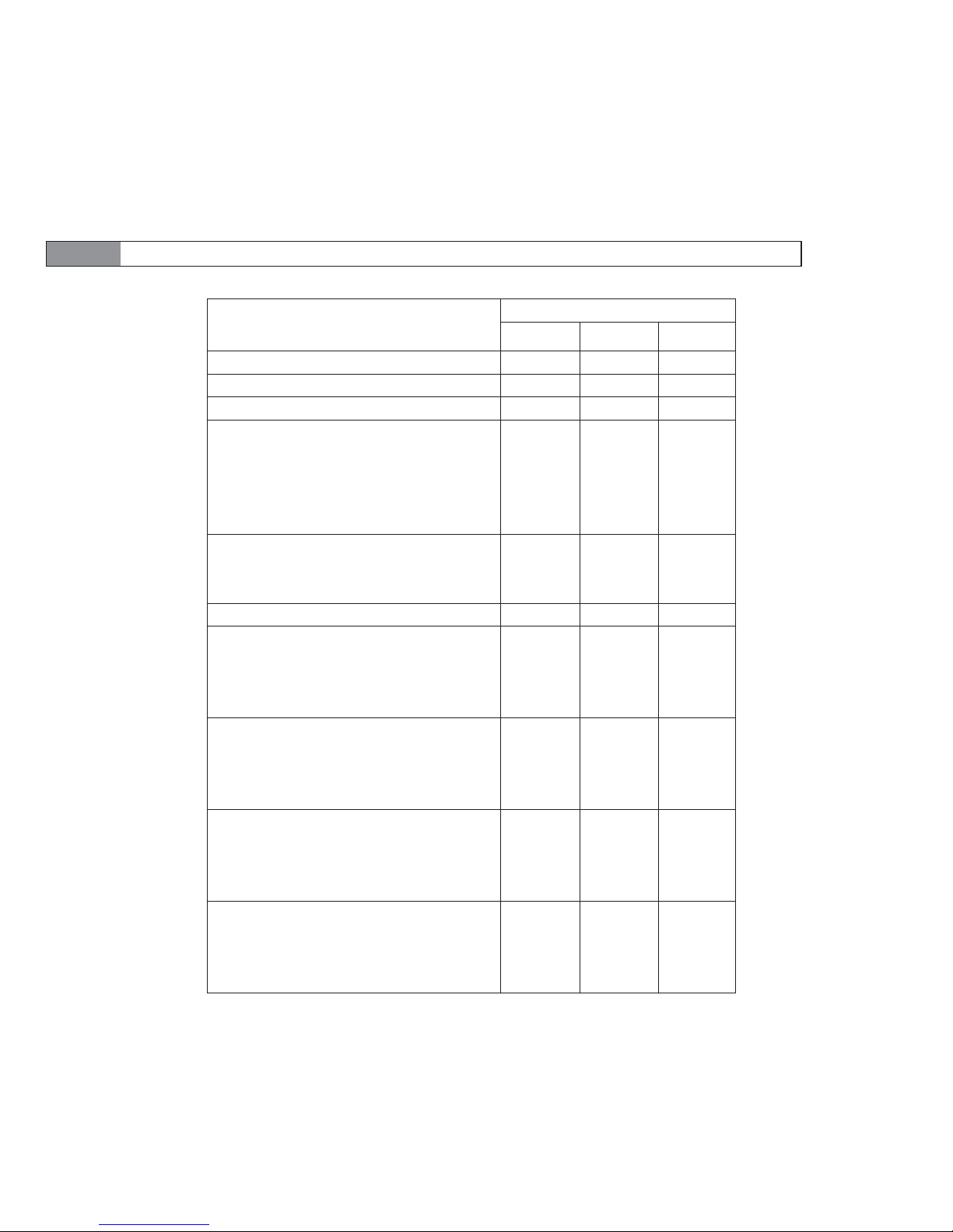
This manual describes the functional, mechanical and interface specifications for the following
Seagate® Enterprise Capacity 2.5 HDD v3 SATA model drives:
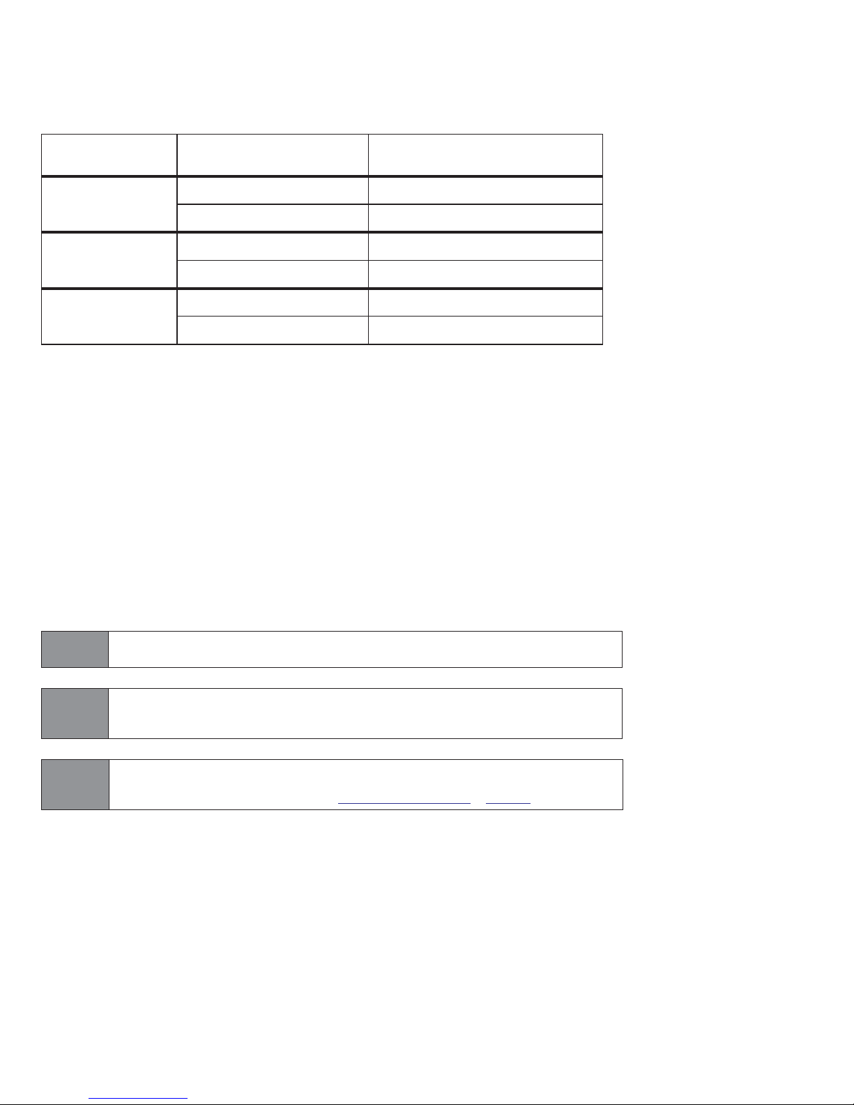
Sector Size Standard models
ST2000NX0243 ST2000NX0283
4096N
ST1000NX0303 ST1000NX0343
ST2000NX0253 ST2000NX0303
512E
ST1000NX0313 ST1000NX0353
ST2000NX0403
512N
ST1000NX0423
These drives provide the following key features:
• 7200 RPM spindle speed.
• 128 MB data buffer.
• PowerChoice™ for selectable power savings
• Top Cover Attached motor for excellent vibration tolerance
• High instantaneous (burst) data-transfer rates (up to 600MB per second).
• Perpendicular recording technology provides the drives with increased areal density.
• State-of-the-art cache and on-the-fly error-correction algorithms.
• Native Command Queuing with command ordering to increase performance in demanding applications.
• Full-track multiple-sector transfer capability without local processor intervention.
• SeaTools™ diagnostic software performs a drive self-test that eliminates unnecessary drive returns.
• Support for S.M.A.R.T. drive monitoring and reporting.
• Supports latching SATA cables and connectors.
• Worldwide Name (WWN) capability uniquely identifies the drive.
Self-Encrypting Drive
(SED) models
Note
Note
Note
Seagate recommends validating the configuration with the selected HBA/RAID
controller manufacturer to ensure use of full capacity is supported.
Previous generations of Seagate Self-Encrypting Drive models were called Full
Disk Encryption (FDE) models before a differentiation between drive-based
encryption and other forms of encryption was necessary
The Self-Encrypting Drive models indicated on the cover of this product manual
have provisions for “Security of Data at Rest” based on the standards defined by
the Trusted Computing Group (see www.trustedcomputinggroup.org).
Seagate Enterprise Capacity 2.5 HDD v3 SATA Product Manual, Rev. D 6

1.1 About the Serial ATA interface
The Serial ATA interface provides several advantages over the traditional (parallel) ATA interface. The primary advantages
include:
• Easy installation and configuration with true plug-and-play connectivity.
It is not necessary to set any jumpers or other configuration options.
• Thinner and more flexible cabling for improved enclosure airflow and ease of installation.
• Scalability to higher performance levels.
In addition, Serial ATA makes the transition from parallel ATA easy by providing legacy software support. Serial ATA was
designed to allow users to install a Serial ATA host adapter and Serial ATA disk drive in the current system and expect all of
the existing applications to work as normal.
The Serial ATA interface connects each disk drive in a point-to-point configuration with the Serial ATA host adapter. There is
no master/slave relationship with Serial ATA devices like there is with parallel ATA. If two drives are attached on one Serial
ATA host adapter, the host operating system views the two devices as if they were both “masters” on two separate ports.
This essentially means both drives behave as if they are Device 0 (master) devices.
The host adapter may, optionally, emulate a master/slave environment to host software
where two devices on separate Serial ATA ports are represented to host software as a
Note
Device 0 (master) and Device 1 (slave) accessed at the same set of host bus addresses.
A host adapter that emulates a master/slave environment manages two sets of shadow
registers. This is not a typical Serial ATA environment.
The Serial ATA host adapter and drive share the function of emulating parallel ATA device behavior to provide backward
compatibility with existing host systems and software. The Command and Control Block registers, PIO and DMA data
transfers, resets, and interrupts are all emulated.
The Serial ATA host adapter contains a set of registers that shadow the contents of the traditional device registers, referred
to as the Shadow Register Block. All Serial ATA devices behave like Device 0 devices. For additional information about how
Serial ATA emulates parallel ATA, refer to the “Serial ATA: High Speed Serialized AT Attachment” specification. The
specification can be downloaded from www.serialata.org.
Seagate Enterprise Capacity 2.5 HDD v3 SATA Product Manual, Rev. D 7
2.0 Drive specifications
Unless otherwise noted, all specifications are measured under ambient conditions, at 25°C, and nominal power. For
convenience, the phrases the drive and this drive are used throughout this manual to indicate the following drive models:
Sector Size Standard models
Self-Encrypting Drive
(SED) models
ST2000NX0243 ST2000NX0283
4096N
ST1000NX0303 ST1000NX0343
ST2000NX0253 ST2000NX0303
512E
ST1000NX0313 ST1000NX0353
ST2000NX0403
512N
ST1000NX0423
2.1 Specification summary tables
The specifications listed in the following tables are for quick reference. For details on specification measurement or
definition, see the appropriate section of this manual.
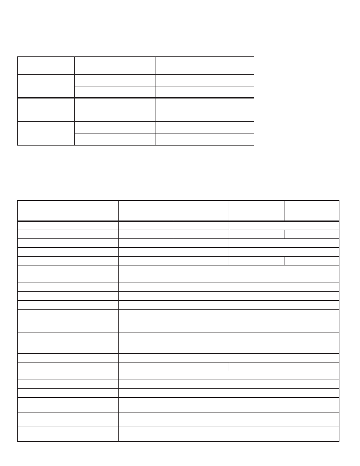
Table 1Drive specifications summary
Drive specification
Formatted (512 bytes/sector)* 2TB 1TB
Guaranteed sectors 488,378,646 3,907,029,168 244,190,646 1,953,525,168
Heads 10 5
Discs 5 3
Bytes per sector 4096 512 4096 512
Recording density, KBPI (Kb/in max) 1889
Track density, KTPI (ktracks/in avg.) 315
Areal density, (Gb/in2 avg) 585
Spindle speed (RPM) 7200
Internal data transfer rate (Mb/s max) 2160
Sustained data transfer rate OD (MiB/s
max)
I/O data-transfer rate (MB/s max) 600
ATA data-transfer modes supported
Cache buffer 128MB (129,536KB)
Weight: (maximum) 198g (0.437 lb) 190g (0.419 lb)
Average latency 4.16ms
Power-on to ready (sec) (max) 20
Standby to ready (sec) (max) 20
Startup current (typical) 12V (peak)
Voltage tolerance (including noise)
Ambient temperature
ST2000NX0243
ST2000NX0283
1.85A (optional configuration through Smart Command Transport)
ST2000NX0253
ST2000NX0303
ST2000NX0403
130 (136 MB/s max)
PIO modes 0–4
Multiword DMA modes 0–2
Ultra DMA modes 0–6
2.0A
5V ±5%
12V ±5%
5° to 55°C (operating/tested)
–40° to 70°C (nonoperating)
ST1000NX0303
ST1000NX0343
ST1000NX0313
ST1000NX0353
ST1000NX0423
Seagate Enterprise Capacity 2.5 HDD v3 SATA Product Manual, Rev. D 8
ST1000NX0313
ST1000NX0353
ST1000NX0423
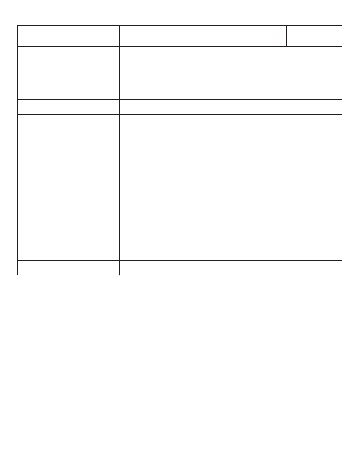
Drive specification
Temperature gradient (°C per hour
max)
Relative humidity
ST2000NX0243
ST2000NX0283
ST2000NX0253
ST2000NX0303
ST2000NX0403
20°C (operating)
20°C (nonoperating)
5% to 95% (operating)
5% to 95% (nonoperating)
ST1000NX0303
ST1000NX0343
Relative humidity gradient 20% per hour max
Altitude, operating
Altitude, nonoperating
(below mean sea level, max)
–304.8 m to 3,048 m
(–1000 ft to 10,000+ ft)
–304.8 m to 12,192 m
(–1000 ft to 40,000+ ft)
Operational Shock (max at 2 ms) 25 Gs
Non-Operational Shock (max at 2 ms) 400 Gs
Vibration, operating 10–500 Hz: 0.5 Gs
Operation Rotational vibration
20–1500Hz: 16 rads/s²
Vibration, nonoperating 10–500 Hz: 2.4 Grms ref
Drive acoustics, sound power (bels)
Idle**
Performance seek
Nonrecoverable read errors 1 sector per 10
2.8 (typical)
3.0 (max)
3.2 (typical)
3.4 (max)
15
bits read
Annualized Failure Rate (AFR) 0.44% based on 8760 POH
To determine the warranty for a specific drive, use a web browser to access the following
web page:
Warranty
http://www.seagate.com/support/warranty-and-replacements/.
From this page, click on the “Check to see if the drive is under Warranty” link. The following
are required to be provided: the drive serial number, model number (or part number) and
country of purchase.The system will display the warranty information for the drive.
Load-unload cycles 300,000 (25°C, 50% rel. humidity) (600,000 design life testing)
Supports Hotplug operation per
Serial ATA Revision 3.2 specification
Yes
*One GB equals one billion bytes when referring to hard drive capacity. Accessible capacity may vary depending on operating environment and formatting.
**During periods of drive idle, some offline activity may occur according to the S.M.A.R.T. specification, which may increase acoustic and power to operational
levels.
Seagate Enterprise Capacity 2.5 HDD v3 SATA Product Manual, Rev. D 9
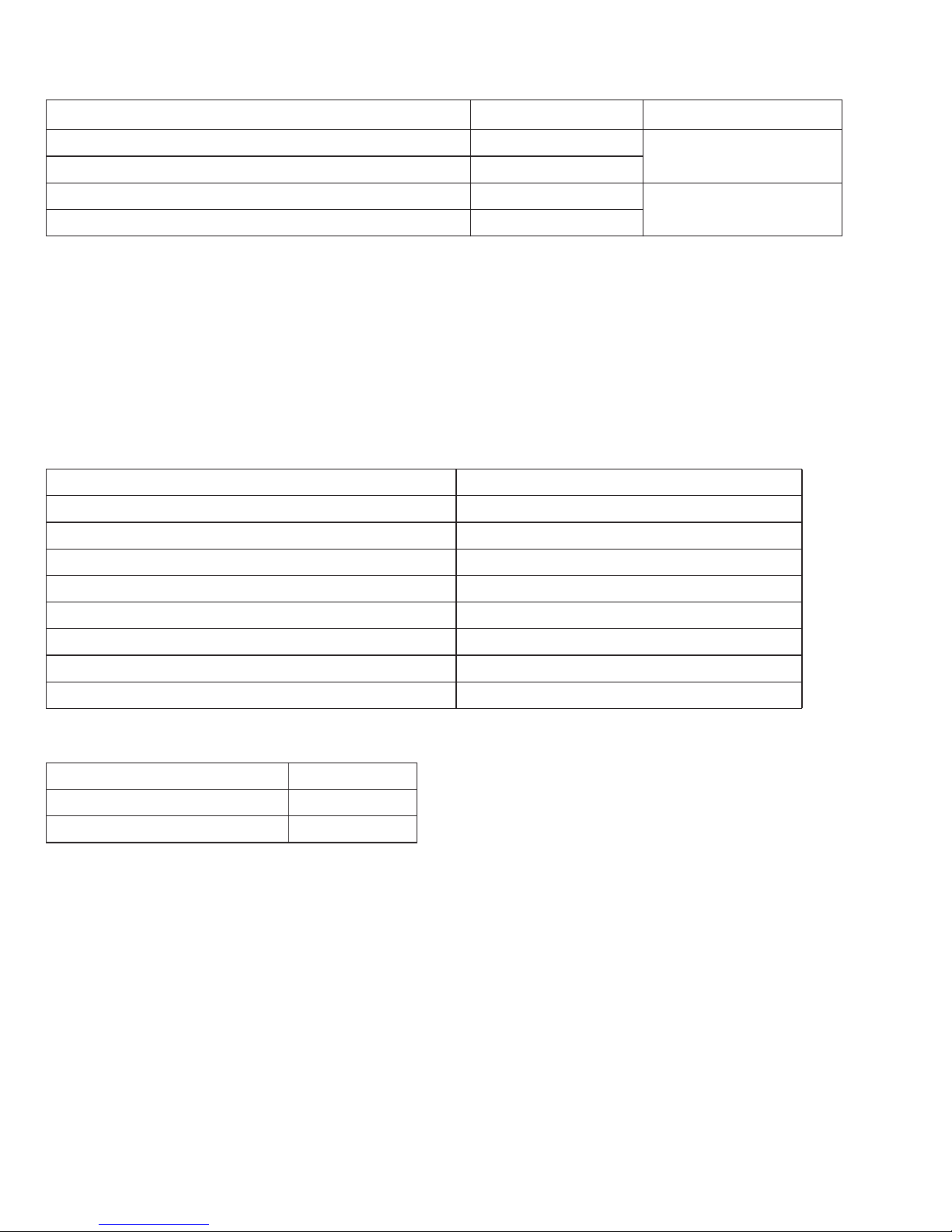
2.2 Formatted capacity
Formatted capacity* Guaranteed sectors Bytes per logical sector
ST2000NX0253, ST2000NX0303 and ST2000NX0403 3,907,029,168
ST1000NX0313, ST1000NX0353 and ST1000NX0423 1,953,525,168
ST2000NX0243, ST2000NX0283 488,378,646
ST1000NX0303, ST1000NX0343 244,190,646
*One GB equals one billion bytes when referring to hard drive capacity. Accessible capacity may vary depending on operating environment and formatting.
512
4096
2.2.1 LBA mode
When addressing these drives in LBA mode, all blocks (sectors) are consecutively numbered from 0 to n–1, where n is the
number of guaranteed sectors as defined above.
See Section 5.3.1, "Identify Device command" (words 60-61 and 100-103) for additional information about 48-bit addressing
support of drives with capacities over 137GB.
2.3 Recording and interface technology
Interface Serial A T A (SAT A)
Recording method Perpendicular
Recording density, KBPI (Kb/in max) 1889
Track density, KTPI (ktracks/in avg) 315
Areal density (Gb/in2 avg) 585
Spindle speed (RPM) (± 0.2%) 7200
Internal data transfer rate (Mb/s max) 2160
Sustained data transfer rate (MiB/s max) 130 (136 MB/s max)
I/O data-transfer rate (MB/s max) 600 (Ultra DMA mode 5)
2.4 Start/stop times
Power-on to Ready (sec) (max) 20
Standby to Ready (sec) (max) 20
Ready to spindle stop (sec) (max) 20
Seagate Enterprise Capacity 2.5 HDD v3 SATA Product Manual, Rev. D 10
2.5 Power specifications
The drive receives DC power (+5V and +12V) through a native SATA power connector. See Figure 4 on page 25.
2.5.1 Power consumption
Power requirements for the drives are listed in Table 2 and Table 3. Typical power measurements are based on an average
of drives tested, under nominal conditions, using 5.0V and 12.0V input voltage at 25°C ambient temperature.
Operation at 3 Gb mode reduces the +5V supply load by 3mA with a commensurate power reduction of 15mW.
Note
There is no measurable impact to the 12V supply load when running at lower interface speeds.
Table 2 2TB standard drive DC power requirements
6.0Gb mode
(Amps) (Amps) (Watts)
Voltage +5V +12V Total
Regulation ± 5% ± 5%
Avg idle current DC * 0.44 0.16 4.12
Advanced Idle Current *
Idle_A 0.44 0.16 4.12
Idle_B 0.22 0.10 2.30
Idle_C 0.21 0.07 1.89
Standby 0.18 0.02 1.14
Maximum starting current
(peak DC) DC 0.50 0.70
(peak AC) AC 0.79 0.97
Delayed motor start (max) DC 0.19 0.03 1.31
Operating current (random read):
Typical DC 0.30 0.31 5.22
Maximum DC 0.38 0.34 5.98
Maximum (peak) DC 1.12 0.89
Operating current (random write)
Typical DC 0.30 0.30 5.10
Maximum DC 0.36 0.34 5.88
Maximum (peak) DC 1.12 0.92
Operating current (sequential read)
Typical DC 0.48 0.17 4.44
Maximum DC 0.55 0.19 5.03
Maximum (peak) DC 0.70 0.33
Operating current (sequential write)
Typical DC 0.44 0.20 4.60
Maximum DC 0.49 0.22 5.09
Maximum (peak) DC 0.60 0.33
*During periods of drive idle, some offline activity may occur according to the S.M.A.R.T. specification, which may increase acoustic and power to operational
levels.
Seagate Enterprise Capacity 2.5 HDD v3 SATA Product Manual, Rev. D 11
 Loading...