

Page 1

. . . . . . . . . . . . . . . . . . . . . . . . . . . . . . . . . . . . . . . . . . . . . . . . .
Barracuda 4FC Disc Drive
. . . . . . . . . . . . . . . . . . . . . . . . . . . . . . . . . . . . . . . . . . . . . . . . .
ST15150FC
. . . . . . . . . . . . . . . . . . . . . . . . . . . . . . . . . . . . . . . . . . . . . . . . .
. . . . . . . . . . . . . . . . . . . . . . . . . . . . . . . . . . . . . . . . . . . . . . . . .
. . . . . . . . . . . . . . . . . . . . . . . . . . . . . . . . . . . . . . . . . . . . . . . . .
Product Manual, Volume 1
. . . . . . . . . . . . . . . . . . . . . . . . . . . . . . . . . . . . . . . . . . . . . . . . .
Page 2

Page 3

. . . . . . . . . . . . . . . . . . . . . . . . . . . . . . . . . . . . . . . . . . . . . . . . .
Barracuda 4FC Disc Drive
. . . . . . . . . . . . . . . . . . . . . . . . . . . . . . . . . . . . . . . . . . . . . . . . .
ST15150FC
. . . . . . . . . . . . . . . . . . . . . . . . . . . . . . . . . . . . . . . . . . . . . . . . .
. . . . . . . . . . . . . . . . . . . . . . . . . . . . . . . . . . . . . . . . . . . . . . . . .
. . . . . . . . . . . . . . . . . . . . . . . . . . . . . . . . . . . . . . . . . . . . . . . . .
Product Manual, Volume 1
. . . . . . . . . . . . . . . . . . . . . . . . . . . . . . . . . . . . . . . . . . . . . . . . .
Page 4

© 1995 Seagate Technology, Inc. All rights reserved
September 1995
Publication number: 83329080, Rev. A
Seagate®, Seagate Technology®, and the Seagate logo are registered trademarks of Seagate
Technology, Inc. Elite
TM
, SeaFAXTM, SeaFONETM, SeaTDDTM, and SeaBOARDTM are trademarks of Seagate Technology, Inc. Other product names are registered trademarks or trademarks of their owners.
No part of this publication may be reproduced in any form without written permission from
Seagate Technology, Inc.
Printed in the United States of America
Page 5

Revision status summary sheet
Revision Date Writer/Engineer Sheets Affected
A (draft 1) 4/14/95 L. Newman/J. Coomes All
A (draft 2) 4/17/95 L. Newman/J. Coomes All
A (draft 3) 4/27/95 L. Newman/J. Coomes All
A (draft 4) 5/22/95 L. Newman/J. Coomes All
A (draft 5) 6/19/95 L. Newman/J. Coomes All
A (draft 6) 8/24/95 L. Newman/J. Coomes All
A 9/5/95 L. Newman/J. Coomes All
Page 6

Page 7

ST15150FC Product Manual, Rev. A vii
Contents
1.0 Scope . . . . . . . . . . . . . . . . . . . . . . . . . . . . . . . . . . . . . . . . . . . . . . . . . . . . . . . . . . . . . . . . . . . . . . . . . . 1
2.0 Applicable standards and reference documentation. . . . . . . . . . . . . . . . . . . . . . . . . . . . . . . . . . . . 3
2.1 Standards. . . . . . . . . . . . . . . . . . . . . . . . . . . . . . . . . . . . . . . . . . . . . . . . . . . . . . . . . . . . . . . . . 3
2.2 Reference documents . . . . . . . . . . . . . . . . . . . . . . . . . . . . . . . . . . . . . . . . . . . . . . . . . . . . . . . 3
3.0 General description. . . . . . . . . . . . . . . . . . . . . . . . . . . . . . . . . . . . . . . . . . . . . . . . . . . . . . . . . . . . . . . 5
3.1 Standard features. . . . . . . . . . . . . . . . . . . . . . . . . . . . . . . . . . . . . . . . . . . . . . . . . . . . . . . . . . . 6
3.2 Media description. . . . . . . . . . . . . . . . . . . . . . . . . . . . . . . . . . . . . . . . . . . . . . . . . . . . . . . . . . . 6
3.3 Performance. . . . . . . . . . . . . . . . . . . . . . . . . . . . . . . . . . . . . . . . . . . . . . . . . . . . . . . . . . . . . . . 6
3.4 Reliability . . . . . . . . . . . . . . . . . . . . . . . . . . . . . . . . . . . . . . . . . . . . . . . . . . . . . . . . . . . . . . . . . 6
3.5 Unformatted and formatted capacities . . . . . . . . . . . . . . . . . . . . . . . . . . . . . . . . . . . . . . . . . . . 7
3.6 Factory-installed accessories. . . . . . . . . . . . . . . . . . . . . . . . . . . . . . . . . . . . . . . . . . . . . . . . . . 7
3.7 Factory-installed options . . . . . . . . . . . . . . . . . . . . . . . . . . . . . . . . . . . . . . . . . . . . . . . . . . . . . 7
3.8 User-installed accessories . . . . . . . . . . . . . . . . . . . . . . . . . . . . . . . . . . . . . . . . . . . . . . . . . . . . 7
4.0 Performance characteristics . . . . . . . . . . . . . . . . . . . . . . . . . . . . . . . . . . . . . . . . . . . . . . . . . . . . . . . 9
4.1 Internal drive characteristics. . . . . . . . . . . . . . . . . . . . . . . . . . . . . . . . . . . . . . . . . . . . . . . . . . . 9
4.2 Seek performance characteristics . . . . . . . . . . . . . . . . . . . . . . . . . . . . . . . . . . . . . . . . . . . . . . 9
4.3 Thermal calibration. . . . . . . . . . . . . . . . . . . . . . . . . . . . . . . . . . . . . . . . . . . . . . . . . . . . . . . . . . 9
4.3.1 Seek time . . . . . . . . . . . . . . . . . . . . . . . . . . . . . . . . . . . . . . . . . . . . . . . . . . . . . . . . 10
4.3.2 Format command execution time for ≥ 512-byte sectors . . . . . . . . . . . . . . . . . . . . 10
4.3.3 General performance characteristics . . . . . . . . . . . . . . . . . . . . . . . . . . . . . . . . . . . 10
4.4 Start/stop time . . . . . . . . . . . . . . . . . . . . . . . . . . . . . . . . . . . . . . . . . . . . . . . . . . . . . . . . . . . . 10
4.5 Prefetch/multi-segmented cache control . . . . . . . . . . . . . . . . . . . . . . . . . . . . . . . . . . . . . . . . 11
4.6 Cache operation. . . . . . . . . . . . . . . . . . . . . . . . . . . . . . . . . . . . . . . . . . . . . . . . . . . . . . . . . . . 11
4.6.1 Caching write data . . . . . . . . . . . . . . . . . . . . . . . . . . . . . . . . . . . . . . . . . . . . . . . . . 12
4.7 Synchronized spindle operation . . . . . . . . . . . . . . . . . . . . . . . . . . . . . . . . . . . . . . . . . . . . . . . 12
5.0 Reliability specifications . . . . . . . . . . . . . . . . . . . . . . . . . . . . . . . . . . . . . . . . . . . . . . . . . . . . . . . . . 15
5.1 Error rates . . . . . . . . . . . . . . . . . . . . . . . . . . . . . . . . . . . . . . . . . . . . . . . . . . . . . . . . . . . . . . . 15
5.1.1 Environmental interference. . . . . . . . . . . . . . . . . . . . . . . . . . . . . . . . . . . . . . . . . . . 15
5.1.2 Interface errors . . . . . . . . . . . . . . . . . . . . . . . . . . . . . . . . . . . . . . . . . . . . . . . . . . . . 15
5.1.3 Write errors. . . . . . . . . . . . . . . . . . . . . . . . . . . . . . . . . . . . . . . . . . . . . . . . . . . . . . . 15
5.1.4 Seek errors. . . . . . . . . . . . . . . . . . . . . . . . . . . . . . . . . . . . . . . . . . . . . . . . . . . . . . . 15
5.2 Reliability and service. . . . . . . . . . . . . . . . . . . . . . . . . . . . . . . . . . . . . . . . . . . . . . . . . . . . . . . 16
5.2.1 Mean time between failure (MTBF) . . . . . . . . . . . . . . . . . . . . . . . . . . . . . . . . . . . . 16
5.2.2 Preventive maintenance . . . . . . . . . . . . . . . . . . . . . . . . . . . . . . . . . . . . . . . . . . . . . 16
5.2.3 Service life . . . . . . . . . . . . . . . . . . . . . . . . . . . . . . . . . . . . . . . . . . . . . . . . . . . . . . . 16
5.2.4 Service philosophy . . . . . . . . . . . . . . . . . . . . . . . . . . . . . . . . . . . . . . . . . . . . . . . . . 16
5.2.5 Service tools . . . . . . . . . . . . . . . . . . . . . . . . . . . . . . . . . . . . . . . . . . . . . . . . . . . . . . 16
5.2.6 Product warranty. . . . . . . . . . . . . . . . . . . . . . . . . . . . . . . . . . . . . . . . . . . . . . . . . . . 16
5.2.7 Hot plugging the drive. . . . . . . . . . . . . . . . . . . . . . . . . . . . . . . . . . . . . . . . . . . . . . . 17
6.0 Physical/electrical specifications . . . . . . . . . . . . . . . . . . . . . . . . . . . . . . . . . . . . . . . . . . . . . . . . . . 19
6.1 AC power requirements . . . . . . . . . . . . . . . . . . . . . . . . . . . . . . . . . . . . . . . . . . . . . . . . . . . . . 19
6.2 DC power requirements . . . . . . . . . . . . . . . . . . . . . . . . . . . . . . . . . . . . . . . . . . . . . . . . . . . . . 19
6.2.1 Conducted noise immunity . . . . . . . . . . . . . . . . . . . . . . . . . . . . . . . . . . . . . . . . . . . 20
6.2.2 Power sequencing . . . . . . . . . . . . . . . . . . . . . . . . . . . . . . . . . . . . . . . . . . . . . . . . . 20
6.2.3 12V current profile . . . . . . . . . . . . . . . . . . . . . . . . . . . . . . . . . . . . . . . . . . . . . . . . . 20
6.3 Power dissipation . . . . . . . . . . . . . . . . . . . . . . . . . . . . . . . . . . . . . . . . . . . . . . . . . . . . . . . . . . 20
6.4 Environmental limits . . . . . . . . . . . . . . . . . . . . . . . . . . . . . . . . . . . . . . . . . . . . . . . . . . . . . . . . 21
6.4.1 Temperature . . . . . . . . . . . . . . . . . . . . . . . . . . . . . . . . . . . . . . . . . . . . . . . . . . . . . . 21
6.4.2 Relative humidity . . . . . . . . . . . . . . . . . . . . . . . . . . . . . . . . . . . . . . . . . . . . . . . . . . 21
6.4.3 Effective altitude (sea level reference) . . . . . . . . . . . . . . . . . . . . . . . . . . . . . . . . . . 21
6.4.4 Shock and vibration . . . . . . . . . . . . . . . . . . . . . . . . . . . . . . . . . . . . . . . . . . . . . . . . 21
6.4.5 Air cleanliness. . . . . . . . . . . . . . . . . . . . . . . . . . . . . . . . . . . . . . . . . . . . . . . . . . . . . 22
Page 8

viii ST15150FC Product Manual, Rev. A
6.5 Electromagnetic susceptibility . . . . . . . . . . . . . . . . . . . . . . . . . . . . . . . . . . . . . . . . . . . . . . . . .22
6.6 Mechanical specifications . . . . . . . . . . . . . . . . . . . . . . . . . . . . . . . . . . . . . . . . . . . . . . . . . . . .23
7.0 Defect and error management . . . . . . . . . . . . . . . . . . . . . . . . . . . . . . . . . . . . . . . . . . . . . . . . . . . . .25
7.1 Drive internal defects/errors . . . . . . . . . . . . . . . . . . . . . . . . . . . . . . . . . . . . . . . . . . . . . . . . . .25
8.0 Installation . . . . . . . . . . . . . . . . . . . . . . . . . . . . . . . . . . . . . . . . . . . . . . . . . . . . . . . . . . . . . . . . . . . . .27
8.1 Drive ID/option selection . . . . . . . . . . . . . . . . . . . . . . . . . . . . . . . . . . . . . . . . . . . . . . . . . . . . .27
8.2 LED connections . . . . . . . . . . . . . . . . . . . . . . . . . . . . . . . . . . . . . . . . . . . . . . . . . . . . . . . . . . .27
8.2.1 J20 connector requirements . . . . . . . . . . . . . . . . . . . . . . . . . . . . . . . . . . . . . . . . . .28
8.3 Drive orientation . . . . . . . . . . . . . . . . . . . . . . . . . . . . . . . . . . . . . . . . . . . . . . . . . . . . . . . . . . .29
8.4 Cooling . . . . . . . . . . . . . . . . . . . . . . . . . . . . . . . . . . . . . . . . . . . . . . . . . . . . . . . . . . . . . . . . . .29
8.4.1 Air flow. . . . . . . . . . . . . . . . . . . . . . . . . . . . . . . . . . . . . . . . . . . . . . . . . . . . . . . . . . .29
8.5 Drive mounting . . . . . . . . . . . . . . . . . . . . . . . . . . . . . . . . . . . . . . . . . . . . . . . . . . . . . . . . . . . .31
8.6 Grounding . . . . . . . . . . . . . . . . . . . . . . . . . . . . . . . . . . . . . . . . . . . . . . . . . . . . . . . . . . . . . . . .31
9.0 Interface requirements. . . . . . . . . . . . . . . . . . . . . . . . . . . . . . . . . . . . . . . . . . . . . . . . . . . . . . . . . . . .33
9.1 General description . . . . . . . . . . . . . . . . . . . . . . . . . . . . . . . . . . . . . . . . . . . . . . . . . . . . . . . . .33
9.2 FC-AL features . . . . . . . . . . . . . . . . . . . . . . . . . . . . . . . . . . . . . . . . . . . . . . . . . . . . . . . . . . . .33
9.2.1 Fibre Channel link service frames . . . . . . . . . . . . . . . . . . . . . . . . . . . . . . . . . . . . . .33
9.2.2 Fibre Channel task management functions . . . . . . . . . . . . . . . . . . . . . . . . . . . . . . .33
9.2.3 Fibre Channel task management responses. . . . . . . . . . . . . . . . . . . . . . . . . . . . . .33
9.2.4 Fibre Channel port login. . . . . . . . . . . . . . . . . . . . . . . . . . . . . . . . . . . . . . . . . . . . . .34
9.2.5 Fibre Channel port login accept. . . . . . . . . . . . . . . . . . . . . . . . . . . . . . . . . . . . . . . .35
9.2.6 Fibre Channel Process Login (PRLI). . . . . . . . . . . . . . . . . . . . . . . . . . . . . . . . . . . .35
9.2.7 Fibre Channel Process Accept (ACC) . . . . . . . . . . . . . . . . . . . . . . . . . . . . . . . . . . .35
9.2.8 Fibre Channel Arbitrated Loop options . . . . . . . . . . . . . . . . . . . . . . . . . . . . . . . . . .36
9.3 Dual port support. . . . . . . . . . . . . . . . . . . . . . . . . . . . . . . . . . . . . . . . . . . . . . . . . . . . . . . . . . .36
9.4 SCSI interface commands supported . . . . . . . . . . . . . . . . . . . . . . . . . . . . . . . . . . . . . . . . . . .36
9.4.1 Inquiry data . . . . . . . . . . . . . . . . . . . . . . . . . . . . . . . . . . . . . . . . . . . . . . . . . . . . . . .38
9.4.2 Mode Sense data. . . . . . . . . . . . . . . . . . . . . . . . . . . . . . . . . . . . . . . . . . . . . . . . . . .39
9.5 Miscellaneous operating features and conditions . . . . . . . . . . . . . . . . . . . . . . . . . . . . . . . . . .40
9.6 FC-AL physical interface . . . . . . . . . . . . . . . . . . . . . . . . . . . . . . . . . . . . . . . . . . . . . . . . . . . . .41
9.6.1 Physical characteristics . . . . . . . . . . . . . . . . . . . . . . . . . . . . . . . . . . . . . . . . . . . . . .41
9.6.2 Connector requirements . . . . . . . . . . . . . . . . . . . . . . . . . . . . . . . . . . . . . . . . . . . . .42
9.6.3 Electrical description . . . . . . . . . . . . . . . . . . . . . . . . . . . . . . . . . . . . . . . . . . . . . . . .42
9.6.4 Pin descriptions . . . . . . . . . . . . . . . . . . . . . . . . . . . . . . . . . . . . . . . . . . . . . . . . . . . .43
9.6.5 Synchronized spindles interface . . . . . . . . . . . . . . . . . . . . . . . . . . . . . . . . . . . . . . .44
9.7 Signal characteristics . . . . . . . . . . . . . . . . . . . . . . . . . . . . . . . . . . . . . . . . . . . . . . . . . . . . . . .48
9.7.1 TTL input characteristics . . . . . . . . . . . . . . . . . . . . . . . . . . . . . . . . . . . . . . . . . . . . .48
9.7.2 LED driver signals . . . . . . . . . . . . . . . . . . . . . . . . . . . . . . . . . . . . . . . . . . . . . . . . . .48
9.7.3 Low drive LED signals . . . . . . . . . . . . . . . . . . . . . . . . . . . . . . . . . . . . . . . . . . . . . . .48
9.7.4 Differential PECL output . . . . . . . . . . . . . . . . . . . . . . . . . . . . . . . . . . . . . . . . . . . . .48
9.7.5 Differential PECL input. . . . . . . . . . . . . . . . . . . . . . . . . . . . . . . . . . . . . . . . . . . . . . .49
10.0 Technical support services. . . . . . . . . . . . . . . . . . . . . . . . . . . . . . . . . . . . . . . . . . . . . . . . . . . . . . . .51
Index . . . . . . . . . . . . . . . . . . . . . . . . . . . . . . . . . . . . . . . . . . . . . . . . . . . . . . . . . . . . . . . . . . . . . . . . . .53
Page 9
ST15150FC Product Manual, Rev. A 1
1.0 Scope
This manual describes Seagate Barracuda 4FC (Fibre Channel) disc drives.
Barracuda 4FC drives support the Fibre Ch annel Arbitrate d Loop and S CSI Fi bre Chan nel Pro tocol specif ica-
tions to the extent des cribed in th is manu al. The
77767496) describes the general Fibre Channel Arbitrated Loop characteristics of this and other Seagate Fibre
Channel drives.
Fibre Channel Arbitrated Loop Prod uct Manu al
(part number
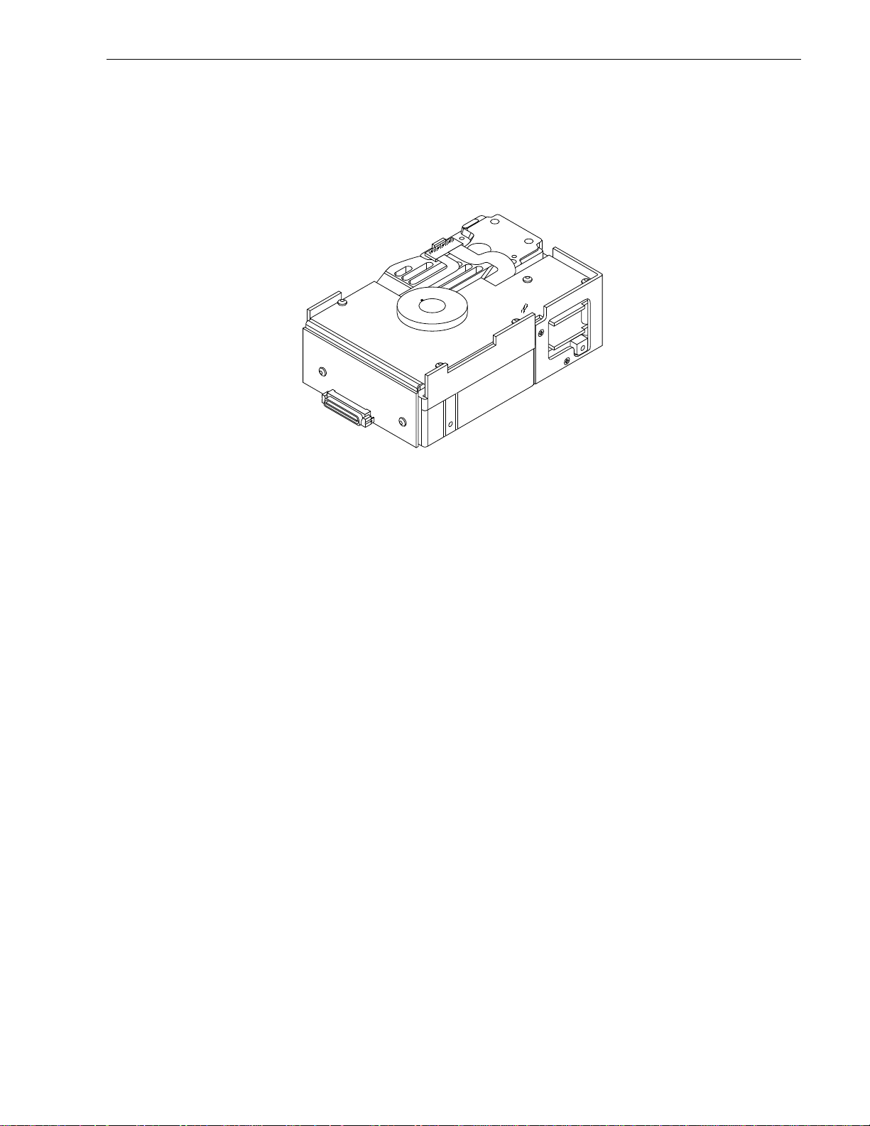
Figure 1. Barracuda 4FC family disc drive
Page 10

Page 11

ST15150FC Product Manual, Rev. A 3
2.0 Applicable standards and reference documentation
Seagate takes all reasonable steps to insure that its produ cts are certifiable to currently a ccepted standards.
Typical applications of these disc drives include customer packaging and subsystem design.
Safety agencies conditionally certify compon ent assemblies, such as the Barracuda 4FC disc drive, based on
their final acceptability in the end-use product. The subsystem designer is responsible for meeting these conditions of acceptability in obtaining safety/reg ulatory agency compliance in their end use product and certifying
where required by law.
2.1 Standards
The Barracuda 4FC disc drive is designed to be a UL recognized compon ent per UL1950, CSA certified to
CSA C22.2 No 950-M89, and VDE certified to VDE 0805 and EN60950.
The Barracuda 4FC disc drive is supplied as a component part. It is the responsibility of the subsystem
designer to meet EMC/regulatory requirements established by the FCC, DOC, and VDE. Engineering test
characterizations of radiated emissions are available from the Seagate safety department.
2.2 Reference documents
ST15150FC Installation Guide
Seagate part number: 83329070
Fibre Channel Arbitrated Loop (FC-AL) Product Manual
Seagate part number: 77767496
SCSI Interface Product Manual
Seagate part number: 77738479
ANSI Fibre Channel Documents
X3.230-199x FC Physical and Signaling Interface (FC-PH)
X3.xxx-199x FC Arbitrated Loop (FC-AL)
X3T10-993.D Fibre Channel Protocol for SCSI (FCP)
TBD Direct Disk Attachment Profile
ANSI Small Computer System Interface (SCSI) Documents
X3T9.2/86-109 Rev. 10H (SCSI-2)
X3T10-994D (SCSI-3) Architecture Model
In case of conflict between this document and any referenced document, this document takes precedence.
Page 12

Page 13
ST15150FC Product Manual, Rev. A 5
3.0 General description
Barracuda 4FC drives are random access storage devices designed to support the Fibre Channel Arbitrated
Loop (FC-AL) and SCSI Fib re Channel Protocol as described in the ANSI specificati ons, this document, and
Fibre Channel Arbitrated Loop Product Manual
the
face characteristics of this drive.
You can view the Fibre Channel interface simply as a transport vehicle for the supported command set
(ST15150FC drives use the SCSI command set). In fact, the Fibre Channel interface is unaware of the content
or meaning of the information be ing transported. It simply packs the SCSI comma nds in packets, transports
them to the appropriate devices, and provides error checking to ensure that the information reaches its dest ination accurately. Refer to the documents referenced in Se ct ion 2.2 if you require additional information about
the Fibre Channel interface, FC-AL topology, or the SCSI fibre channel protocol.
The head and disc assembly (HDA) is environm entally sealed at the factory. Air recirculates within the HDA
through a non-replaceable filter to maintain a contamination-free HDA environment.
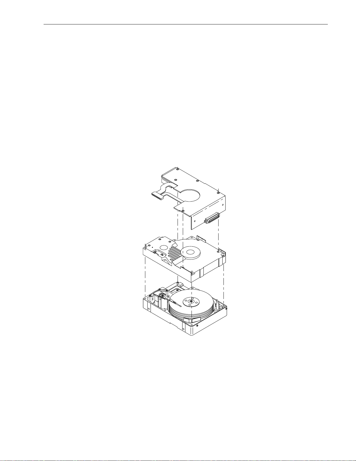
Refer to Figure 2 for an explode d view of the drive. Never disassemble the HDA . This exploded view is for
information only. Do not attempt to service items in the sealed en closure (hea ds, media, actuat or, etc.) as this
requires special facilitie s. The drive contains no p arts replaceable by the user and opening the HDA for any
reason voids your warranty.
(part number 77767496) which describes the general inter-
Figure 2. Barracuda 4FC disc drive
Barracuda 4FC drives use a dedicated landing zone at the innermo st radi us of the me dia to eli minate the pos sibility of destroying or degrading data by landing in the data zone. The head s automatical ly go to the landing
zone when power is removed from the drive.
An automatic shipping lock prevents potential damage to the heads and discs that results from movement during shipping and handling. The shippin g lock disengages and the head load process begins when power is
applied to the drive.
Barracuda 4FC drives decode track 0 locat ion data from the dedicate d servo surface to eliminate mechanical
transducer adjustments and related reliability concerns.
The drives also use a high-performance actu ator assembly design that provides excellent performance with
minimum power dissipation.
Page 14

6 ST15150FC Product Manual, Rev. A
3.1 Standard features
Barracuda 4FC drives have the following standard features:
• Integrated dual port FC-AL controller
• Support for FC-AL (Fibre Channel Arbitrated Loop)
• Differential copper FC drivers and receivers
• Downloadable firmware using the FC-AL interface
• Drive selection ID and configurati on options are set on the FC-AL backpanel , T-card, or through interface
commands. Jumpers are not required on the drive.
• FC world-wide name uniquely identifies the drive and each port
• Supports up to 16 initiators
• User-selectable logical block size (180 to 4,096 bytes)
• Reallocation of defects on command (Post Format)
• User-selectable number of spare sectors per cylinder
• Industry standard 3.5-inch full-high form factor dimensions
• Programmable sector realloca tion scheme
• Flawed sector reallocation at format time
• Programmable autowrite and read reallocation
• Reallocation of defects on command (post format)
• 96-bit Reed-Solomon error correction code
• Sealed head and disc assembly (HDA)
• No preventive maintenance or adjustments required
• Dedicated head landing zone
• Automatic shipping lock
• Automatic thermal compensation
• Embedded Grey Code track address to eliminate seek errors
• Self-diagnostics performed at power on
• 1:1 interleave
• Zone bit recording (ZBR)
• Vertical, horizontal, or top down mounting
• Dynamic spindle brake
• 998 Kbyte data buffer
3.2 Media description
The media used on the dri ve has a diameter of approximately 95 m m (approximately 3.7 inches). The alum inum substrate is coated with a thin film ma gnetic material, overcoated with a proprietary protecti ve layer for
improved durability and environmental protection.
3.3 Performance
• Programmable multi-segmentable cache buffer
• 106.3 Mbytes/sec maximum instantaneous data transfers
• 7,200 RPM spindle; average latency = 4.17 msec
• Command queuing of up to 64 commands
• Background processing of queue
• Supports start and stop commands
• Provides synchronized spindle capability
• Adaptive seek velocity; improved seek performance
3.4 Reliability
• 800,000 hour MTBF (Class A computer room environment)
• Fibre Channel (FC) interface transports SCSI protocol through CRC protected frames
• LSI circuitry
• Balanced low mass rotary voice coil actuator
Page 15

ST15150FC Product Manual, Rev. A 7
3.5 Unformatted and formatted capacities
The standard OEM models are formatted to 512 bytes per block.
ST15150FC drives have nine (9) spare sectors per cylinder and one (1) spare cylinder per unit.
Formatted Unformatted
ST15150FC 4,294 Mbytes 5,062 Mbytes
Users having the necessary equipment may modi fy the data bl ock size before issuing a format command an d
obtain different formatted capacities than those listed. User-available capacity also depends on the spare reallocation scheme you select. See the Mode Select command and the Fo rmat command in the
Arbitrated Loop Product Manual
(part number 77767496).
Fibre Channel
3.6 Factory-installed accessories
OEM standard drives are shipped with the Barracuda 4FC Installation Guide (part number 83329070).
3.7 Factory-installed options
You may order the following items which are incorporated at the manufacturing facility during production or
packaged before shipping:
• Black plastic front panel with green lens (part number 70553702).*
• Black plastic front panel with red lens (part number 70553701).*
• Single-unit shipping pack. The drive is normally shipp ed in bulk packaging to provide maximum protection
against transit damage. Units shipped individually require additional protection as provided by the single unit
shipping pack. Users planning single unit distribution should specify this option.
• ST15150FC Installation Guide, part number 83329070.
*You may order other front panel colors. Each panel has a single rectangul ar LED indicator lens that, when
glowing, indicates the drive is selected.
3.8 User-installed accessories
The following accessories are available. All kits may be installed in the field.
• Front panel kit (green lens), part number 70869751.
• Single-unit shipping pack kit.
• Adapter accessory frame kit, part number 75790701.
(adapts a 3.5-inch drive to fit in a 5.25-inch drive mounting space).
This kit contains the frame to allow a 3.5-inch drive to be mounted in a 5.25-inch drive bay. It includes mounting hardware, front panel with a green lens, an LED with cable that connects to the remote LE D connector,
and installation instructions.
• Evaluation kit, part number 70935895.
This kit provides an adapter card ( “T-card”) to allow cable con necti ons fo r two FC inte rfaces an d D C p ower.
T wo twin axial cables, 6-feet in length, are included for the input and output connections to the FC interfaces.
A small DC fan is included for cooling.
Page 16

Page 17

ST15150FC Product Manual, Rev. A 9
4.0 Performance characteristics
This section provides detailed information concerning performance-related characteristics and features of Barracuda 4FC drives.
4.1 Internal drive characteristics
ST15150FC
Drive capacity 5.062..................................Gbytes (unformatted)
Read/write data heads 21
Bytes per track 64,160................................Bytes (average)
Bytes per surface 232.4..................................Mbytes (unformatted)
Cylinders/tracks per surface 3,711..................................Tracks (user accessible)
Tracks per inch 4,048..................................TPI
Bits per inch 73,820................................BPI
Servo heads 1
Internal data rate 47.5 - 72.0.........................Mbytes/sec (variable with zone)
Disc rotation speed 7,200 ± 0.5%.....................rpm
Avg rotational latency 4.17....................................msec
4.2 Seek performance characteristics
All performance characteristics assume that the rmal calibration is not in process when th e SCSI command is
received. A SCSI command being executed is not interrup ted for therma l calib ratio n. If therma l calib ratio n is in
process when a SCSI command is received, the command is queu ed until the compensation for the specific
head being calibrated com pletes. When compensation completes for the spe cific head being calibrated, the
first queued SCSI command is executed.
Refer to paragraph 9.6, “FC-AL physical interface” and to the
Fibre Channel Arbitrat ed Loop Product Manual
(part number 77767496) for additional timing details.
4.3 Thermal calibration
ST15150FC drives use an automatic therma l calibrati on (TCAL) process to mai ntain a ccurate head al ignmen t
with the data cylinders. The host s ytem may choose to allow the drive to perform TCAL at th e drive’s predefined intervals or the Rezero Unit command may be issued by the host to reset the TCAL timer so that the
host knows when the TCAL will occur.
1. At power up and following a SCSI reset, the drive calibrate s al l of the he ads before any re ad or write co m-
mands are processed. All heads are also calibrated during the SCSI Rezero Unit command.
2. The drive delays 300 seconds before initiating any TCALs. No TCALs occur during this delay period.
3. A single-head TCAL is then scheduled at 7.1 second intervals.
4. After the drive TCALs all of the heads, the interval is increased to schedule a single head TCAL every 14.3
seconds.
5. The drive attempts to find an idle period of 25 to 50 milliseconds prior to performing a single head TCAL. If
this TCAL is delayed for another interval of time, the drive forces the TCAL at the next command boundary.
This guarantees that no head will remain uncalibrated for more than 600 seconds (2 * 21 heads * 14.3 seconds per head) and that no TCALs are closer together than the interval time.
Note. Any TCAL performed during the “standard” retry sequence is limited to the failing head and is disabled
if the host has selects a retry count of zero.
Page 18

10 ST15150FC Product Manual, Rev. A
4.3.1 Seek time
Including drive
controller overhead
Drive level (msec) (msec)
Read Write Read Write
Average typical
Single track typical
Full stroke typical
1. Rate measured from the start of the first sector transfer to or from the host.
2. Typical seek values are measured under nominal conditions of temperature, voltage, and horizontal orientation as measured on a representative sample of drives.
2
2
2
8.09.09.010.0
0.60.91.61.9
17 19 18.0 20.0
1
4.3.2 Format command execution time for ≥ 512-byte sectors
Maximum (with verify) 60 minutes
Maximum (without verify) 40 minutes
4.3.3 General performance characteristics
Minimum sector interleave 1 to 1
Data buffer to/from disc media (512-byte sector)
Data transfer burst rate (≤ 1 sector)
Min
Max
5.30 Mbytes/sec*
8.94 Mbytes/sec*
Data transfer sustained rate (< 1 track)
Min (divided by interleave factor)
Max (divided by interleave factor)
FC-AL interface data
Maximum instantaneous transfer rate 106.3 Mbytes/sec
Sector sizes
Default is 512-byte data blocks
Variable (180- to 4,096-bytes) in multiples of four bytes
Read/write consecutive sectors on a track Yes
Flaw reallocation performance impact (for flaws reallocated using the
spare sectors per track reallocation scheme
Flaw reallocation performance impact (for flaws reallocated using the
spare sectors per cylinder reallocation scheme)
Flaw reallocation performance impact (for flaws reallocated using the
spare tracks per volume reallocation scheme
Overhead time for head switch (512 byte sectors) 0.7 msec
Overhead time for one track cylinder switch 1.6 msec (typical)
Average rotational latency 4.17 msec
*Assumes no errors and no relocated sector s.
3.56 Mbytes/sec*
7.65 Mbytes/sec*
Negligible
Negligible
35 msec (typical)
4.4 Start/stop time
If the Motor Start optio n is disa bled, the drive b ecomes ready w ith 30 seconds after DC power i s applied. If a
recoverable error condition is detected during the start sequence, the drive executes a recovery procedure and
the time to become ready may exceed 30 seconds. During the st art sequence, the drive responds to some
commands over the FC-AL interface. Stop time is less than 30 seconds (maximum) from removal of DC power.
Page 19

ST15150FC Product Manual, Rev. A 11
If the Motor Start option is ena bl ed, the int ernal control ler accep ts the comm ands l isted in the
Product Manual
been received, the drive becomes ready for normal operations within 30 seconds (excluding the error recovery
procedure). The Motor Start command can also be used to co mmand the dri ve to stop the spindl e (see Start/
Stop command information in the
There is no power control switch on the drive.
4.5 Prefetch/multi-segmented cache control
The drive provides a prefetch/multi-segmented cache algo rithm that in many cases can enhance system performance. To sel ect t his featu re th e host sen ds th e M ode Sel ect com man d w ith the p roper val ues in the ap pl icable bytes in page 08h (see the
cache enabled.
4.6 Cache operation
Of the 1,024 Kbytes physical buffer space in the drive, 998 Kbytes can be used as a cache. The cache can be
divided into logical segments from which data is read and to which data is written.
The drive keeps track of the logical block addresses of the data stored in each segment of the cache. If the
cache is enabled (see RCD bit in the
host with a read command is retrieved f rom the cache, i f possible, befo re any disc access is initiate d. Data in
contiguous logical blocks immediately beyond that requested by the Read command can be retrieved and
stored in the cache for immediate transfer to the initiator on subsequent read commands. This is referred to as
the prefetch operation. Since data that is prefetched may replace data alrea dy in the cache segment, an in iti ator can limit the amount of prefetch data to optimize system pe rformance. The drive never prefetches more
sectors than the number specified in bytes 8 and 9 of Mode page 08h (see
Product Manual
writes, with no prefetch operation and no segmented cache operation.
less than 3 seco nds after DC power has been ap plied. After the Motor Start com mand has
Fibre Channel Arbitrated Loop Product Manual
Fibre Channel Arbitrated Loop Product Manual
Fibre Channel Arbitrated Lo op Product Manu al
).
). Default is prefetch and read
), data requested by the
Fibre Channel Arbitrated Loop
). If the cache is not enabl ed, 998 Kbytes of the buffer are used as a circular buffer for read/
FC-AL Interface
The following is a simplified description of the prefetch/cache operation:
Case A—read command is received and the first logical block is already in cache:
1. Drive transfers to the initiator the first logical block requested plus all subsequent contiguous logical blocks
that are already in the cache. This data may be in multiple segments.
2. When a requested logical bl oc k is reached t hat i s not i n any seg men t, the drive fe t ches it a nd any re mai ning requested logical block addresses from t he disc and puts them in a segment of the cache. The d rive
transfers the remaining requested logical blocks from the cache to the initiator in accordance with the
“buffer-full” ratio specification given in Mode Select Di sconnect/Re connect pa ramete rs, page 02h (see the
Fibre Channel Arbitrated Loop Product Manual
3. The drive prefetches additional logical blocks contiguo us to those transferred in step 2 above and stores
them in the segment. The drive stops filling the segment when the maximum p refetch value has been
transferred (see the
Case B—read command is received an d th e fi r st log ical block address reque ste d is not in a ny segm ent o f th e
cache.
1. The drive fetches the requested logical blocks from the d isc and transfers them into a segme nt, and the n
from there to the initiator in accordance with the “buffer-full” ratio specifi cation given in Mode Select Disconnect/Reconnect parameters, page 02h (see the
2. The drive prefetches additional logical blocks contiguous to those transferred in Case A, step 2 above and
stores them in the segment. The drive stops filling the segment when the maximum prefetch value has
been transferred.
During a prefetch, the drive crosses a cyli nde r bou nda ry to fe tch da ta o nl y if the Disconti nui ty (DIS C) bi t is set
to 1 in bit 4 of byte 2 of the Mode Select parameters page 8h. De fault is zero for bit 4 (see the
Arbitrated Loop Product Manual
Fibre Channel Arbitrated Loop Product Manual
).
).
).
Fibre Channel Arbitrated Loop Product Manual
).
Fibre Channel
Each cache segment is actually a self-contained circul ar buffer whose length is an integer num ber of sectors.
The wrap-around capability of the individual segments greatly enhances the cache’s overall performance,
allowing a wide range of user-selectable configurations. The drive supports operation of any integer number of
Page 20
12 ST15150FC Product Manual, Rev. A
segments from 1 to 16. Divide the 998 Kbytes in the buffer by the number of segments to get the segment size.
Default is 3 segments. (See the
Fibre Channel Arbitrated Loop Product Manual.
)
4.6.1 Caching write data
Write caching is a write operation by the drive that makes use of a drive buffer storage area where the data to
be written to the medium is stored while the drive performs the Write command.
Write caching is enabled independently of read caching. The default write cache setting for ST15150FC drives
is with write caching disabled. To enable the write cache, use the Write Caching Enable (WCE) bit.
For write caching, the same buffer space and segmentatio n is used as set up for rea d fun cti ons. When a writ e
command is issued, the cache is first checked to see if any logical b locks that are to be written are already
stored in the cache from a previous read o r write command. If there are, the respective cache segments are
cleared. The new data is cached for subsequent read commands.
If a 10-byte CDB Write command (2Ah) is issued with the data page out (DPO) bit set to 1, no write data is
cached, but the cache segmen ts are still checked and cleared, if need be, for any logi cal blocks that are bein g
written (see the
Fibre Channel Arbitrated Loop Product Manual
).
If the number of write data logical blocks exceeds the size of the segment being written into when the e nd of
the segment is reached, the data is written into the beginning of the same cache segment, overwriting the data
that was written there at the beginning of the operation. However, the drive does not overwrite data that has not
yet been written to the medium.
4.7 Synchronized spindle operation
Synchronized spindle operation allows several drives operating from the same host to operate their spindles at
the same synchronized rotational rate. Drives operating in a system in synchronized mode increase the system
capacity and transfer rate in a cost-effective manner.
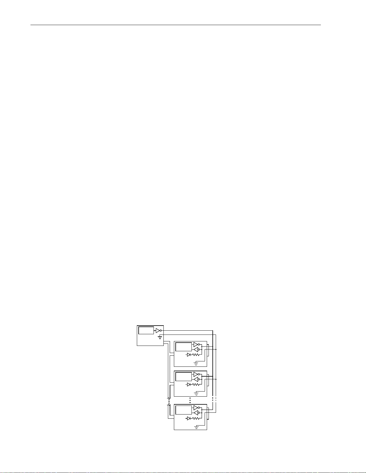
The spindle sync signal is routed in the backpanel to connect th e dri ves in the synchroni zed s ystem as show n
in Figure 3.
Each drive in the system can be configured by the host (using a Mode Select command) to ope rate in either
the master or slave mode. Drives can be re-configured by the host any time after power-up to be master or
slave by use of the Mode Se lect command Rigid Disc Drive Ge ometry page. The master provides the reference signal to which all other drives phase-lock, including the master. There is only one master per system,
and that can be a drive or the host computer. All drives may be configured as slaves allowing the host to provide the reference signal.
Each drive can be configured for the non-synchronized mode in which it ignores any re ference signal that
might be present—this is the de fault mode as shipped from the facto ry. The connection of the synchronized
reference signal to the host is required only if the host is to provide the reference signal. If the ho st does not
provide the reference signal, the host should not be connected.
Sync Interface
Master Sync
Source
Host
(or other drive)
System
Interface
Spindle
Control
+5V
Drive 1
Spindle
Control
+5V
Drive 2
J6
8
R
T
J6
8
R
T
Figure 3. Synchronized drive interconne ct d iagram
Spindle
Control
+5V
Drive n
J6
8
R
T
Page 21
ST15150FC Product Manual, Rev. A 13
Rotational Position Locking
Note. Mode Select page 4, byte 17, bits 1 and 0.
RPL Description
00b Indicates that spindle synchronization is disabled (default val ue)
01b The target operates as a synchronized spindle slave
10b The target operates as a synchronized spindle master
11b The target operates as a synchronized spindle master control
(not supported by the disc drive)
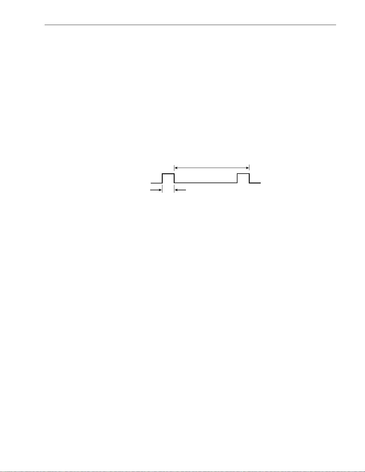
The Pike LSI on the master drive provides the reference signal (SSREF+). The index signal generates a 120
Hz signal. The signal is normally false/negated (nominal 0V) and makes a transition to the true/asserted (nominal +5V) level to indicate the re ference p ositi on d urin g the revolu tio n pe riod. The m aster and slave d rives use
the trailing (falling) edge of the reference signal to phase-lock their spindles. A maxi mum of 10 seconds is
allowed for a slave to synchronize with the reference signal.
Figure 4 shows the characteristics of the reference signal.
T
SSREF +
T = 0.0083 second (± 1.0% max); ± 10 µsec cycle to cycle variance; ± 20 µsec phase error while synchronized
1
0
1.0 µsec min.
1.37 µsec max.
Figure 4. Synchronized reference signal characteristics
SCSI factors
The Rotational Position Lockin g (RPL) field in byte 17 (bits 0 and 1) of the Rigid Disc Drive Geometry mode
parameters page (page 04h) is used for enabling and disabling spindle synchronization mode (see the
Channel Arbitrated Loop Prod uct Manual
). When the target achieves synchronizatio n, it creates a unit atten-
Fibre
tion to all initiators. The sense key is set to Unit Attention and the additiona l sense code set to Spindles Synchronized (5C01).
If subsequent to achieving synchronization the target detects a change of synchronization and:
1. If the logical unit is not executi ng an I/O process for the initiat or, the target creates a unit attention condition. The sense key is set to Unit Attention and the addi tional sense code set to Spindle Synchronized
(5C01) or Spindle Not Synchronized (5C02).
2. If the logical unit is executing an I/O process and no other error occurs, the target returns Check Condition
status. The sense key is set to Recovered Error if the target is able to complete th e I/O process or Hardware Error if the target is unable to complete the I/O process. The additional sense code is set to Spindles
Synchronized (5C01) or Spindles Not Synchronized (5C02).
The drive may be operated with a rotational skew when synchronized. The rotational skew is applied in the
retarded direction (lagging the synchronized spind le master control). A rotational offset of up to 2 55/256 of a
revolution lagging ma y be selected. The amount of offset is selecte d by using the Mode Select command,
Rigid Disc Drive Geometry page (pag e 04), byte 18 ( see the
Fibre Channel Arbitrated Loop Product Manua l
The value in byte 18 (0-FFh) is the numerator o f a fractional multiplier that has 256 a s the denominator. For
example, 40h selects 40h/FFh or 1/4 of a revolution lagging skew; 80h selects 1/2 revolution lagging skew, etc.
Since the drive supports all offset values from 0 to 255, values sent by the initiator are not rounded off. The
drive translation of the digital offset values to physical rotational offsets results in offset values wh ose phase
error lies within the ±20 µsec phase error with respect to the supplied 120 Hz reference signal.
).
The drive does not have the capability to adjust the rot atio nal offset value reque sted by the ini tiator to a physical offset in the drive that corresponds in any way to sector bound arie s or changes in ZBR zon es. Such correspondences or changes, if required, must b e formulated by the initiator for it to calculate the val ue of offset it
sends to the drive.
Page 22

Page 23

ST15150FC Product Manual, Rev. A 15
5.0 Reliability specifications
The following reliability specifi cations assume correct host and drive operational interface, includi ng all interface timings, power supply voltages, and environmental requirements.
Seek error rate: Less than 10 errors in 108 seeks
Recoverable media error rate
(using default settings):
Unrecovered media data: Less than 1 sector in 10
Miscorrected media data: Less than 1 sector in 10
Interface error rate: Less than 1 error in 1012 bits transferred with minimum receive eye. Less than 1
MTBF: 800,000 hours
Service life: 5 years
Preventive maintenance: None required
Less than 10 errors in 10
14
error in 10
ential PECL input.”
bits transferred with typical receive eye. See Section 9.7.5, “Differ-
5.1 Error rates
The error rates stated in this manual assume the following:
• The drive is operated in accordance w ith this manual using DC power as defined in pa ragraph 6.2, “DC
power requirements.”
• The drive has been formatted with the SCSI format commands.
• Errors caused by media defects or host system fai lu res are exclud ed fro m error rate comp utati on s. Refer t o
Section 3.2, “Media descriptio n.”
11
bits transferred
14
bits transferred
21
bits transferred
5.1.1 Environmental interference
When evaluating systems operation under conditions of electrom agnetic interference (EMI), the performance
of the drive within the s ystem is con sidered accepta bl e if the drive does n ot g ene rate a n un recove rabl e cond ition.
An unrecoverable error, or condition, is defined as one that:
• is not detected and corrected by the drive itself, or
• is not capable of being dete cted from the error o r faul t statu s p rovided throu gh th e dri ve or FC -AL inte rface ,
or
• is not capable of being recovered by normal drive or s ystem recovery procedures with out op erator interven-
tion.
5.1.2 Interface errors
An interface error is defined as a failure of the receiver on a port to recover the data as transmitted by the
device port connected to the receiver. The error may be detected as a running disparity error, illegal code, loss
of word sync, or CRC error. The total error rate for a loop o f devices is the sum of th e individual de vice error
rates.
5.1.3 Write errors
Write errors can occur as a result of media defects, e nvironmental interference, or equ ipment malfunction.
Therefore, write errors are not predictable as a function of the number of bits passed.
If an unrecoverable write error occurs because of an equipment malfunction in the drive, the error is classified
as a failure affecting MTBF. Unrecoverable write errors are those that cannot be corrected with in two a ttem pts
at writing the record with a read verify after each attempt (excluding media defects).
5.1.4 Seek errors
A seek error is defined as a failure of the drive to position the hea ds to the a ddressed track. There must be n o
more than one recoverable seek error in 10
7
physical seek operations. Aft er de tectin g a n initia l seek error, the
drive automatically reseeks to t he addressed track up to three time s. If a reseek is successful, the Exte nded
Sense reports a seek positioning error (15h), no seek comp lete error (02h), or track follow error (09h), and the
Page 24

16 ST15150FC Product Manual, Rev. A
sense key reports a recovered error (1h). If all three reseeks fail, a seek positioning error (15h) is reported with
a Medium (3h) or Hardware error (4h) reported in the Sense Key. This is an unrecoverable seek error. Unrecoverable seek errors are classified as failures for MTBF calculations. Refer to paragraph 5.1.1.2 of
Channel Arbitrated Loop Product Manual
5.2 Reliability and service
The reliability of Barracuda 4FC disc drives can be enhanced by ensuring that the drive receives adequate
cooling. This section provides recommended air-flow information, temperature measurements, and other information, which may be used to enhance the service life of the drive.
5.2.1 Mean time between failure (MTBF)
The production disc drive achieves a n MTBF of 800,000 hours when ope rated in an average local disc drive
ambient temperature of 9 5°F (35°C) o r less. Sho rt-term excursions up to the spe cificat ion limits of the op erating environment will not affect MTBF performance.
The following expression defines MTBF:
MTBF = Estimated power-on operating hours in the period
Estimated power-on operating ho urs means the estimate d total power-on h ours for all drives in service. Drive
failure means any stoppage or substandard performance caused by drive malfunction.
(part number 77767496).
Number of drive failures in the period
Fibre
Data is calculated on a rolling-average base for a minimum period of six months.
5.2.2 Preventive maintenance
No routine scheduled preventive maintenance is required.
5.2.3 Service life
The drive has a useful service life of five years. Depot repair or rep lacem ent of m ajor parts is permitt ed d urin g
the lifetime.
5.2.4 Service philosophy
Special equipment is required to repair the drive HDA. To achieve the above service life, repairs must be performed only at a properly equi pped a nd staffed service and rep air facility. Troubleshooting and repair of PCBs
in the field is not recommended because of the extensive diagnostic equipment required for effective servicing.
Also, there are no spare parts available for this drive. The drive warranty is voided if the HDA is opened.
5.2.5 Service tools
No special tools are required for site installation or recommended for site maintenance. Refer to paragraph
5.2.2, “Preventive main tenance.” The depot repair philosophy of the drive precludes th e necessity for special
tools. Field repair of the drive is not practical because users cannot purchase individual parts for the drive.
5.2.6 Product warranty
Beginning on the date of shipme nt to the custom er and co nti nui ng fo r a period of fi ve years, Seagat e warrants
that each product (including components and subassemblies) or spare part that fails to function properly under
normal use due to defect in materials or workmanshi p or due to nonconformance to the applicab le specifications will be repaired or replaced, at Seagate’s option and at no charge to the customer, if returned by customer at customer’s expense to Seagate’s designated facility in accordance with Seagate’s warranty
procedure. Seagate will pay for transportin g th e repa ir or repl aceme nt i tem to th e custome r. For more detailed
warranty information, refer to the standard terms and conditions of purchase for Seagate products on your purchase documentation.
Page 25

ST15150FC Product Manual, Rev. A 17
Shipping
When transporting or shipping a drive, a Seaga te approved containe r must be used. Keep you r original box.
They are easily identifie d by the Seagate Approved Package label. Shipping a drive i n a non-approved container voids the drive warranty.
Seagate repair centers may refuse recei pt o f comp one nts imprope rly packaged or ob vi ousl y d ama ged in transit. Contact your auth orized Seaga te distributor to purchase additional boxes. Seagate recom mends shipp ing
by an air-ride carrier experienced in handling computer equipment.
Product repair and return information
Seagate customer service centers are the onl y facilities authorized to service Seagate drives. Seagate does
not sanction any third-party repair facilities. Any unauthorized rep air or tampering with t he factory-seal voids
the warranty.
5.2.7 Hot plugging the drive
Inserting and removing the drive o n the FC-AL will disrupt loop op eration. The disruption occurs when the
receiver of the next device in the loop must s ynchronize to a d ifferent input signal. FC e rror detection mechanisms, character sync, running disparity, word sync, and CRC are able to detect any error. Recovery is initiated
based on the type of error.
The Barracuda 4FC disc drive defaults to the FC-AL Monitorin g st ate, Pass-through state, when it is powe redon by switching the power or hot plugged. The control l ine to an optional port bypass circuit (external to the
drive), defaults to the Enable Bypass state. If the bypass circuit is present, the next device in the loop will continue to receive the output of the previous device to the newly inserted device. If the bypass circuit is not
present, loop operation is temp oraril y d isrupted unt il the n ext device sta rts receivi ng th e ou tput from th e ne wly
inserted device and regains synchronization to the new input.
The Pass-through state is disabled wh ile th e d isc perfo rms self test o f th e FC int erface. The con trol line for a n
external port bypass circuit remains in the Enable Bypass state while self test is running. If the bypass circuit is
present, loop operation may continue. If the bypass circuit is not present, loop operation will be halted while the
self test of the FC interface runs.
When the self test completes successfully, the control line to the bypass circuit is disabled and the drive enters
the FC-AL Monitoring state, Pass-though st ate. The receiver on the next device in the loop must synchronize
to output of the newly inserted drive.
If the self test fails, the control line to the bypass circuit remains in the Enable Bypass state.
Note: It is the responsibility of the s ystems integrat or to assure th at n o t emp erature, en ergy, or voltage hazard
is presented during the hot connect/disconn ect (hot plug) operation. Discharge the static electricity from th e
drive carrier prior to inserting it into the system.
Page 26

Page 27

ST15150FC Product Manual, Rev. A 19
6.0 Physical/electrical specifications
This section provides information relating to the physical and ele ctrical characteristics of Barracuda 4FC disc
drives.
6.1 AC power requirements
None.
6.2 DC power requirements
The voltage and current requi rements for a single drive are shown bel ow. Values indi cated apply at the drive
connector.
Table 1: DC power requirements
+5V
±5V
Voltage Regulation Notes [5]
Avg idle current [1] [8] 1.03 1.25
Max start current (peak DC) [3] [6] 1.44 2.42
Delayed motor start (max) [1] [4] 1.23 0.67
Operating current
Typical [1] [7] 1.28 1.42
Maximum [1] 1.32 1.49
Max (peak) 1.46 2.35
(Amps)
+12V
[2]
±5V
(Amps)
[1] Measured with average reading DC a mmeter. Instantaneous +12V current peaks will e xceed these val-
ues.
[2] A -10% tolerance is allowed during initial spindle start but must return to ±5% before reaching 7,200 RPM.
The ±5% must be maintained after the drive signifies tha t its power-up sequence has b een completed
and that the drive is able to accept selection by the host initiator.
[3] See +12V current profile in Figure 5.
[4] This condition occurs when the Motor Start option is enabled and the drive has not yet received a Start
Motor command.
[5] See paragraph 6.2.1, “Conducted noise immunity.” Specified voltage tolerance includes ripple, noise, and
transient response.
[6] At power-up the motor current regulator limits the 12V current to an average value o f less than 2.18A,
although instantaneous peaks may exceed thi s value. These peaks should measure 5 msec duratio n or
less.
[7] Operating condition means a third stroke seek at OD and Read One track. A command is issued every
0.075 seconds.
[8] All power-saving features enabled.
General DC power requirement notes.
1. Minimum current loading for each supply voltage is not less than 7% of the maximum operating current
shown.
2. The +5V and +12V supplies should employ separate ground returns.
3. Where power is provided to multiple drives from a common supply, careful consideration for individual
drive power requirements should be noted . Whe re mul tip le units are powered on sim ulta neo usly, the peak
starting current must be available to each device.
Page 28

20 ST15150FC Product Manual, Rev. A
6.2.1 Conducted noise immunity
Noise is specified as a periodic and random distribution of fre quencies covering a band fro m DC to 10 MHz.
Maximum allowed noise val ues given below are peak-to-peak measurements and apply at the d rive power
connector.
+5V +12V (with spindle motor not running)
0 to 100 kHz 150mV 150mV
100 kHz to 10 MHz 100mV 100mV
6.2.2 Power sequencing
The drive does not require power sequencing . The drive protects again st inadvertent writ ing during power-up
and down.
6.2.3 12V current profile
Figure 5 identifies the drive +12V current profile. The current during the various times is as shown:
4
3
Peak AC
Nominal (average) curve
2
+12V CURRENT (A)
1
T0
T1
0
04286101412 16 18 20
T2
TIME (S)
Minimum AC
T3
T4
T5
T6
Figure 5. Typical Barracuda 4FC drive +12V current profile
T0 Power is applied to the drive.
T1 Controller self-tests are performed.
T2 Spindle begins to accelerate under current limiting after performing internal diagnostics.
T3 The spindle is up to speed and the Head-Arm restraint is unlocked.
T4 Heads move from the landing zone to the data area.
T5 The adaptive calibration sequence is performed.
T6 Calibration is complete and the drive is ready for reading and writing.
T7
Note. All times and currents are typical. See Table 1 for maximum current requirements.
6.3 Power dissipation
Typical seek power dissipation is 23 watts (79 BTUs per hour) of DC power average at nominal voltages. Typical power dissipation under idle conditions is 20 watts (68 BTUs per hour).
Page 29

ST15150FC Product Manual, Rev. A 21
6.4 Environmental limits
Temperature and hu midit y val ues experie nced by the drive must be such tha t co nde nsatio n doe s not occur on
any drive part. Altitude and at mospheric pressure specifications are referenced to a standard day at 58.7°F
(14.8°C). Maximum wet bulb temperature is 82°F (28°C).
6.4.1 Temperature
a. Operating
The MTBF specification for the drive (800, 000 h ours) is based on o perati ng at a l ocal amb ien t tem peratu re
of 95°F (35°C). Occasiona l excursions to drive ambi ent temperatures to 122°F (50°C) may occur without
impact to specified MTBF. The enclosure for the drive should be designed such that the case tempe ratures
at the locations specified i n Figures 11 and 12 are not exceeded. Air flow is needed to achie ve these temperature values. Continual or sustained operation at ca se temperatures above these values may degrade
MTBF.
The drive meets all specifications over a 41°F to 122°F (5°C to 50°C) drive ambient temperature range with
a maximum gradient of 36°F (20°C) pe r hour when the case temperature limits specified above are not
exceeded.
b. Non-operating
Non-operating temperature should remain between -40°F to 158°F (-40°C to 70°C) package ambient with a
maximum gradient of 36°F (20°C ) per hour. This assumes that the drive is packaged in the shipp ing container designed by Seagate.
6.4.2 Relative humidity
The values below assume that no condensation on the drive occurs.
a. Operating
5% to 95% relative humidity with a maximum gradient of 10% per hour.
b. Non-operating
5% to 95% relative humidity.
6.4.3 Effective altitude (sea level reference)
a. Operating
-1,000 to +10,000 feet (-305 to +3,048 meters)
b. Non-operating
-1,000 to +40,000 feet (-305 to +12,210 meters)
6.4.4 Shock and vibration
Shock and vibration limits specified in this document are measured directly on the drive chassis. If the drive is
installed in an enclosure to which the stated shock and /or vibrati on c riteria are appl ie d, resona nces may occur
internally to the enclosure resultin g in drive movement in excess of t he stated limits. If this si tuation is apparent, it may be necessary to modify the enclosure to minimize drive movement.
The limits of shock and vibrati on defined within this document are speci fied with the drive mounted in one of
the two methods shown in Figure 9.
6.4.4.1 Shock
a. Operating (normal)
The drive, as installed for normal ope ration, shall operate error free while sub jected to intermittent shock
not exceeding 2.0 Gs at a maximum duration of 11 msecs (half sinewave). Shock may be applied in the X,
Y, or Z axis.
Page 30

22 ST15150FC Product Manual, Rev. A
b. Operating (abnormal)
Equipment as installed for normal operat ion shall not incur physical damage whi le subjected to intermi ttent
shock not exceeding 10 Gs at a maximum duration of 11 msecs (half sinewave). Shock occurring at abnormal levels may promote degraded ope rational performance during the abnormal shock period. Speci fied
operational performance will continue when normal operati ng shock levels resume. Shock may be a pplied
in the X, Y, or Z axis. Shock is not to be repeated more than two times per second.
c. Non-operating
The limits of non-operating sho ck shall app ly to al l co nditio ns of han dling and transpo rtation. This inclu des
both isolated drives and integrated drives.
The drive subjected to non-repetit ive shock not exceedi ng 50 Gs at a maxim um durati on of 11 msecs (half
sinewave) will not exhibit device damage or performance degradation. Shock may be applied in the X, Y, or
Z axis.
d. Packaged
The drive as packaged in a single or multi ple drive pack of gross weight 20 pounds (8.95 kg) or less by
Seagate for general freight shipm ent sha ll withstand a drop test from 48 inches (1,070 m m) again st a co ncrete floor or equivalent.
6.4.4.2 Vibration
a. Operating (normal)
The drive as installed for normal ope ration shall ope rate error free while subj ected to continuous vibra tion
not exceeding:
5-400 Hz @ 0.5 G
Vibration may be applied in the X, Y, or Z axis.
b. Operating (abnormal)
Equipment as installed f or normal operation shall not incur physical dama ge while subjected to periodic
vibration not exceeding:
15 minutes of duration at major resonant frequency
5-400 Hz @ 0.75 G
Vibration occurring at these levels may degrade operating performance during the abnormal vibration
period. Specified operating performan ce will conti nue when normal operati ng vibration le vels are resumed .
This assumes system recovery routines are available. Ab normal vibration may be app lied in the X, Y or Z
axis.
c. Non-op erating
The limits of non-operating vibration shall apply to all conditions of handling and transportation. This
includes both isolated drives and integrated drives.
The drive shall not incur physical damag e or degrad ed performa nce as a resu lt of cont inuous vib ration no t
exceeding:
5-22 Hz @ 0.040 in. (1.02 mm) displacement
22-400 Hz @ 2.00 Gs
Vibration may be applied in the X, Y, or Z axis.
6.4.5 Air clea nliness
The drive is designed to operate in a typical office environment with minimal environmental control.
6.5 Electromagnetic susceptibility
As a component part, the drive is not required to meet any susceptibility performance requ irements. It is the
responsibility of the system integrator to perform tests required to ensure that equipment operating in the same
system as the drive does not adversely affect the performance of the drive. See paragraph 6 .2, “DC power
requirements.”
Page 31

ST15150FC Product Manual, Rev. A 23
6.6 Mechanical specifications
The following nominal dimension s are exclusive of the decorative front panel accessory. Refer to Figure 6 for
detailed mounting configuration dimensions for the drive. A minimum clearance of 0.050 in. (1.27 mm) must be
maintained from the PWA side of the drive.
Height 1.63 in 41.4 mm
Width 4.00 in 101.6 mm
Depth 5.97 in 151.6 mm
Weight 2.3 lb 1.04 kilogram s
M
F
.809 ref
H
B
Motherboard ref
.136
N
K
A
[2]
J
1.875 ± .005 1.875 ± .005
Figure 6. Mounting configuration dimension s
ED
Notes:
Mounting holes two on each
[1]
side, 6-32 UNC. Max screw
length into side of drive is
0.15 in. (3.81 mm).
Mounting holes four on bottom,
[2]
6-32 UNC. Max screw length
into bottom of drive is 0.15 in.
(3.81 mm).
Inches Millimeters
A
5.965
B
4.000
C
1.615
D
.620
E
4.000
F
.250
G
1.750
H
3.750
J
2.365
K
1.750
L
0.181
M
1.615
N
1.839
L
[1]
.508
151.511
101.60
41.02
15.748
101.60
6.35
44.45
95.25
60.071
44.45
4.59
41.021
46.70
±
.25
±
.86
±
.50
±
.13
±
.13
±
.25
±
.25
±
.25
±
.50
±
.381
±
.863
±
.56
±
0.020
±
0.010
±
0.034
±
0.020
±
0.005
±
0.005
±
0.010
±
0.010
±
0.010
±
0.010
±
0.015
±
0.034
±
0.022
±
Page 32

Page 33

ST15150FC Product Manual, Rev. A 25
7.0 Defect and error management
The drive, as delivered, complies wi th th is pro duct m anu al. The read error rates an d spe cifie d storag e cap acities are not dependent upon use of defect management routines by the host (initiator).
Defect and error management in the SCSI protocol involves the drive internal defect/error manageme nt and
FC-AL system error considerations (errors in communications betwe en the initiator and the drive). Tools for
use in designing a defect/error ma nagement p lan are brie fly outlined in th is section. Referen ces to other sections are provided when necessary.
7.1 Drive internal defects/errors
Identified defects are recorde d on the drive defects l ist tracks (referred to as the pri mary or ETF defect list).
These known defects are rea llocated during the initial dri ve format operation at the factory. See the Format
Unit command in the
by ECC is applied to recover data from additional flaws if they occur.
Fibre Channel Arbitrated Loop Produ ct Manu al
(part number 77767496). Data correction
Details of the SCSI comman ds supported by the drive are described in the
Product Manual
Channel Arbitrated Loop Product Manual
. Also, more information on the drive Error Recovery philosophy is presented in the
.
Fibre Channel Arbitrated Loop
Fibre
Page 34

Page 35

ST15150FC Product Manual, Rev. A 27
8.0 Installation
ST15150FC disc drive installation is a plug-and-play process. There are no jumpers, switche s, or terminators
on the drive which need to be set. Simply plug the drive into the ho st’s 40-pin Fibre Channel backpanel connector (FC-SCA)
connector.
The FC-AL interface is used to select drive ID and all option configurations for devices on the loop.
If multiple devices are on the same FC-AL and physical addresses are used, set the device selection IDs (SEL
IDs) on the backpanel so that no two devices have the same selection ID. This is called the hard assigned arbitrated loop physical address (AL_PA). There are 125 AL_PAs available (see Table 18 on page 47). If you set
the AL-P A on the backpanel to any value other than 0, the device plugged into the backpanel’s SCA connector
inherits this AL_PA. In the event you don’t successfully assign un ique hard addresses (and therefore have
duplicate selection IDs assigned to two or more devices), the FC-AL genera tes a message indi catin g this co ndition. If you set the AL-PA on the backpanel to a value of 0, the system issues a unique soft-assigned physical
address automatically.
Loop initialization is the process used to verify or obtain an address. The loop initialization process is performed when power is ap plied to th e drive, when a device is added or removed from the FC l oop, or when a
device times out attempting to win arbitration.
• Set all option selecti ons in the connector prior to applying power to the drive. If you change options after
applying power to the drive, recycle the drive power to activate the new settings.
• It is not necessary to low level format th is drive. The d rive is shippe d from the factory low le vel formatte d in
512-byte sectors. You need to reformat the drive onl y if you want to select a different sector size or if you
select a different spare sector allocation scheme.
–no cables are required. Refe r to Secti on 9.6 on pag e 41 fo r addi tion al info rm ati on ab out th is
8.1 Drive ID/option selection
All ST15150FC drive options are made through the interface connector (J6). Table 15 on page 43 provides the
pin descriptions for the 40-pin FC single connector (J6).
8.2 LED connections
A connector, J20, is provided on the LYJX board to provide port bypass, drive active, and drive fault LED connections (see Figure 8). Refer to Section 9.6.5.3 for a description of the Port Bypass LED function. Refer to
Section 9.6.5.2 for a description of the Active LE D function. Refer to Section 9. 6.4.3 for a description of th e
Fault LED function.
Note. The LYJX-0 board does not have the J20 connector.
J20
J6
Figure 7. Barracuda 4FC drive physical interface
Page 36

28 ST15150FC Product Manual, Rev. A
Pin 1J20
Pin 2
J20
Port A Bypass LED*
Port B Bypass LED*
Active LED*
Fault LED*
Ground
+5V
Figure 8. Barracuda 4FC LED indicator connector
Pin 1
Pin 2
* Low power LED required. See Table 22. The drive
has a 2.26 K resistor in series with this LED driver.
Connect the LED from +5V to the appropriate LED
output pin.
8.2.1 J20 connector requirements
Recommended mating connector part number: Berg receptacle, 6-position, part number 690-006.
Page 37

ST15150FC Product Manual, Rev. A 29
8.3 Drive orientation
The drive may be mounted in an y orientation. All drive performance charact erizations, however, have been
done with the drive in horizontal (discs level) and vertical (drive on its side) orientations, which are the two preferred mounting orientations.
Figure 9. Recommended mounting
8.4 Cooling
Cabinet cooling must be d esigned by th e customer so that the ambi ent temperat ure immediatel y surrounding
the drive will not exceed temperature condit ions specified in Section 6.4.1, “Temperature.” Specific consideration should be given to make sure adequate air circulation is present around the printed circuit board (PCB) to
meet the requirements of Section 6.4.1, “Temperature.”
8.4.1 Air flow
The rack, cabinet, or drawer environment for the Barracuda 4FC drive must provide cooling of the electronics
and head and disc assembly (HDA). You should confirm that adequate cooling is provided using the temperature measurement guidelines described below.
The drive should be oriented, or air flo w directed, so that the least amount of air flow resistance i s created
while providing air flow to the electron ics and HDA. Also, the shortest possib le path between the air inlet an d
exit should be chosen to minimize the travel length of air heated by the drive and other heat sources within the
rack, cabinet, or drawer environment.
Possible air flow patterns are shown in Figure 10. The air flow patterns are created by one or more fans, either
forcing or drawing air as shown in the illustrations. Other air flow patterns are acceptab le as long as the temperature measurement guidelines are met.
Page 38

30 ST15150FC Product Manual, Rev. A
Above unit
Note. Air flows in the direction shown (back to front)
or in reverse direction (front to back)
Note. Air flows in the direction shown or
in reverse direction (side to side)
Under unit
Above unit
Under unit
Figure 10. Air flow
To confirm that the required cooling for the electronics and HDA is provided, place the drive in its final mechanical configuration, perform random write/read operations and, after t he temperatures stabilize, measure th e
case temperature of the components listed below.
Air flow cooling
MTBF
800k hours
Card Component Reference
case temperature (°C)
LYJX Transmitter 1 76
LYJX Writer 2 62
LYJX Memory 3 51
LYJX Aurora 4 73
LYJX Driver 5 55
To obtain the maximum temperature for each of the reference components listed, add 15°C to the 800K MTBF
case temperatures. Operation of the drive at the maximum case temperature is intended for short time periods
only. Continuous operation at the elevated temperatures will reduce product reliability.
The air-flow pattern with which the tem peratu re gui del ines above were ge nerate d is sh own i n Figure 10. Local
average air velocities were 1.2 m/sec (23 0 lfp m) an d inlet air te mpe rature to the drive wa s 30 °C (86 °F), pl us a
5°C temperature rise in the test enclosure (35°C ambient local to the drive).
The maximum allowable HDA case temperature is 60°C (see Figure 12)
Page 39

ST15150FC Product Manual, Rev. A 31
1
Figure 1 1. LYJX temperature measurement locations
2
4
53
1.00
.50
Figure 12. HDA case temperature measurement loca tion
8.5 Drive mounting
Mount the drive using the bottom or side mounting holes. If you mount the drive using the bottom holes, ensure
that you do not physically distort the drive by attempting to mount it on a stiff, non-flat surface.
The allowable mounting surface stiffness is 80 lb/in (14.0 N/mm). The following equation and paragraph define
the allowable mounting surface stiffness:
80 lb
F
k = = or
x
in
14.0 N
mm
where k is the mounting surface stiffness (units in po unds or ne wton ) and x is th e out -of-pla ne d istorti on (un its
in inches or millimeters). The out-of-plane distortion (x) is determi ned by def ining a plane with three of the four
mounting points fixe d and evaluating the out-of-plane defection of the fourth mounting point when a known
force (F) is applied to the fourth point.
8.6 Grounding
Signal ground (PCB) and HDA ground a re connecte d togethe r in the Barracuda 4 family drives—d o not sep arate this connection. Maximizing the condu ctive contact area between HDA ground and system ground may
reduce radiated emissions. A bracket shield with tapped holes is availab le to system integrators. This shield
makes it easier to attach a braid or similar high-frequency grounding de vice. If you do not want the s ystem
chassis to be connecte d to the HDA/PCB ground, you must pro vide a nonconductive (electrically isolatin g)
method of mounting the drive in the host equipment; however, this may increase radiated emissions and is the
system designer’s responsibility.
Page 40

Page 41

ST15150FC Product Manual, Rev. A 33
9.0 Interface requirements
This section partially describes the interface requ irements as implemented on ST1515 0FC drives. Additional
information is provided in the
77738479).
9.1 General description
Fibre Channel Arbitrated Loop Interface Product Manual
(part number
The major portion of the interface requirements/implementation is described in the Seagate
Arbitrated Loop Interface Product Ma nual
. This section provides info rmation about ST15150FC drive imple-
mentation of the FC-AL standard.
9.2 FC-AL features
This section lists the Fibre Channel-specific features supported by ST15150FC drives.
9.2.1 Fibre Channel link service frames
Table 2 lists the link services supported by ST15150FC drives.
Table 2: Link services supported
Type of frame Link service
Basic link service frames Abort Sequence (ABTS)
Basic link service reply frames Basic_Accept (BA_ACC)
Basic_Reject (BA_RJT)
Extended link service frames N_Port Login (PLOGI)
Logout (LOGO)
Process Login (PRLI)
Process Logout (PRLO)
Read Link Status (RLS)
Port Discovery (PDISC)
Extended link service reply frames Accept (ACC)
Link Service Reject (LS_RJT)
Fibre Channel
9.2.2 Fibre Channel task management functions
Table 3 lists the FC SCSI FCP task management functions supported.
Table 3: Fibre Channel SCSI FCP task management functions
Task name Supported
Terminate task No
Clear ACA Yes
Target reset Yes
Clear task set Yes
Abort task set Yes
9.2.3 Fibre Channel task management responses
Table 4 lists the Fibre Channel SCSI FCP response codes returned for task management functions supported.
Table 4: FC SCSI FCP response codes
Function name Response code
Function complete 00
Function not supported 04
Function reject 05
Page 42

34 ST15150FC Product Manual, Rev. A
9.2.4 Fibre Channel port login
Table 5 identifies the required content of the N_Port Login (PLOGI) payload from an initiator.
Table 5: N_Port login (PLOGI) payload
Bytes
0-15 03 00 00 00 09 09 bb bb cf XX fs fs XX XX XX XX Common
16-31 XXXXXXXXPNPNPNPNPNPNPNPNNNNNNNNN
32-35 NN NN NN NN
36-47 XXXXXXXXXXXXXXXXXXXXXXXXClass 1
48-51 XX XX XX XX
52-63 XXXXXXXXXXXXXXXXXXXXXXXXClass 2
64-67 XX XX XX XX
68-79 so so ic ic XXXXfs fs XXcs XXXXClass 3
80-83 os os XX XX
84-95 XXXXXXXXXXXXXXXXXXXXXXXXReserved
96-99 XX XX XX XX
100-111 XX XX XX XX XX XX XX XX XX XX XX XX Vendor
112-115 XX XX XX XX Version
X Indicates a four bit (hex) fiel d is not che cked.
x Indicates a single bit is not checked.
bb BB-Credit. This field is not checked. The FC-AL drive uses BB-Credit of zero.
cf Common features. This bina ry fie ld sel ec ts the common features requested by the initiat or login.
MSB Continuously increasing offset
Random relative offset
Valid version level
N_Port/F_Port
Alternate credit model
Other bits reserved
fs Receive buffer field size. The fs field in the common and Class 3 parameters is checked for the range 128≤ fs ≤
21 12 an d a multiple of four byte s. For multip le frame sequence s, all frames but the last fra me of the s equence must
be this size. Only the receive buffer field size in the Class 3 parameters is used.
PN Port name (initiator’s)—saved with the login parameters. If a change of the port name/AL_PA address association
is detected during a Port DISCovery, an implicit logout occurs and a LS_RJT is returned to the initiato r.
NN Node name. The node name is not checked or saved by the drive.
so Service options Class 3 only
MSB Class valid
Intermix
Stacked connection required
Sequential delivery
Other bits reserved
ic Initiator control
MSB XID reassign
Proc Assc
ACK_0
ACK_N
cs Concurrent sequences Must be a value greater than 0.
os Open sequences per exchange Must be a value greater than 0.
Must = 1
Not checked. Port Login Accept will ret urn a 0—not su ppo rted .
x
Must = 0, N_Port
Must = 1
XXX
Must = 1
x
xx
x
xxx
xx
10 or 11 causes the login to be rejected. Other value s are accepted.
xx
xx
Page 43

ST15150FC Product Manual, Rev. A 35
9.2.5 Fibre Channel port login accept
Table 6 identifies the N_Port Login payload values.
Table 6: N_Port Login (ACC) payload
Bytes
0-15 02 00 00 00 09 09 00 00 88 00 fs fs 00 FF 00 01 Common
16-31 000001F410PP002037ui ui ui 10000020
32-35 37 ui ui ui
36-47 00 00 00 00 00 00 00 00 00 00 00 00 Class 1
48-51 00 00 00 00
52-63 00 00 00 00 00 00 00 00 00 00 00 00 Class 2
64-67 00 00 00 00
68-79 80 00 00 00 00 00 fs fs 00 FF 00 00 Class 3
80-83 00 01 00 00
84-95 000000000000000000000000Reserved
96-99 00 00 00 00
100-111 00 00 00 00 00 00 00 00 00 00 00 00 Vendor 112-115 00 00 00 00 Version
fs Receive buffer field size. The drive returns the fs from the login payload Class 3 parameters in the Common and
Class 3 fields of the Accept payload.
ui Unique identifier. This 24-bit field is uniquely assigned to the drive. This same ui appears in the Port Name and
Node Name.
pp Port identifier field
01 P_LOGI received on Port A.
02 P_LOGI received on Port B.
9.2.6 Fibre Channel Process Login (PRLI)
Table 7 lists ST15150FC process login payload data.
Table 7: Process Login (PLRI) payload
Bytes
0-15 20 10 00 14 08 00 20 00 XX XX XX XX XX XX XX XX
16-1900000022
XX Indicates fields that are not used.
9.2.7 Fibre Channel Process Accept (ACC)
Table 8 lists ST15150FC process login accept payload data.
Table 8: Process Login Accept (ACC) payload
Bytes
0-15 02 10 00 14 08 00 21 00 00 00 00 00 00 00 00 00
16-19 00000012
Page 44

36 ST15150FC Product Manual, Rev. A
9.2.8 Fibre Channel Arbitrated Loop options
Table 9 lists the FC-AL options supported by ST15150FC drives.
Table 9: FC-AL options supported
Option Supported
OPEN Half Duplex Sent to open another device.
Accepted from another device.
OPEN Full Duplex Accepted from another device.
Private Loop Yes
Public Loop No
Old Port State No
Loop Position Yes
Loop Position Report Yes
9.3 Dual port support
ST15150FC drives have two ports for connection to two independent loops. Both loops may be active, but only
one of these ports may be receiving or originating transfers at any one time.
Do not connect both ports to the same loop.
For drives connected to two loops. Port A and Port B must not be mixed on the same loop.
9.4 SCSI interface commands supported
Table 10 lists the SCSI interface commands that ST15150FC drives support.
Table 10: Supported commands
Command code
00h Y Test unit ready
01h Y Rezero unit
03h Y Request sense
04h Y Format unit [1]
07h Y Reassign blocks
08h Y Read
0Ah Y Write
0Bh Y Seek
12h Y Inquiry
15h Y Mode select (same pages as Mode Sense command shown below)
16h N Reserve [3]
17h N Release [3]
Supported
Y Extended sense
Y Field pointer bytes
Y Actual retry count bytes
Y Vital product data page
Y Unit serial number page
Y Implemented operating def. page
Y Firmware numbers page
Y Date code page
Y Jumper settings page
Command name
Page 45

ST15150FC Product Manual, Rev. A 37
Table 10: Supported commands (Continued)
Command code
18h N Copy
1Ah Y Mode sense
1Bh Y Start unit/stop unit
1Ch Y Receive diagnostic results
1Dh Y Send diagnostics page
25h Y Read capacity
28h Y Read extended
2Ah Y Write extended
2Bh Y Seek extended
2Eh Y Write and verify
2Fh Y Verify
30h N Search data high
31h N Search data equal
32h N Search data low
33h N Set limits
34h N Prefetch
35h Y Synchronize cache
36h N Lock-unlock-cache
37h Y Read defect data
39h N Compare
3Ah N Copy and verify
3Bh Y Write buffer
3Ch Y Read buffer
3Eh Y Read long
3Fh Y Write long
40h N Change definition
41h N Write same
42-4Bh N Not used
4Ch N Log select
Supported
Y Unit attention page (00h)
Y Error recovery page (01h)
Y Disconnect/reconnect control (page 02h)
Y Format page (03h)
Y Rigid disc drive geometry page (04h)
Y Verify error recovery page (07h)
Y Caching parameters page (08h)
Y Control mode page (0Ah)
Y Notch and partition page (0C) (media zones)
Y Supported diagnostics pages
Y Translate page
Y Supported diagnostics pages
Y Translate page
Y Firmware download option [2]
Command name
Page 46

38 ST15150FC Product Manual, Rev. A
Table 10: Supported commands (Continued)
Command code
4Dh N Log Sense
4E-54h N Not used
55h Y Mode Select (10)
56h Y Reserved (10)
57h Y Released (10)
58-59h N Not used
5Ah Y Mode Sense (10)
5B-5Fh N Not used
60-BFh N Not used
C0-DFh N Not used
EO-FFh N Not used
Supported
Y 3rd party reserve
N Extend reservation
Command name
[1] The Barracuda 4FC drive can format to any even number of bytes per sector from 180 to 4,096.
[2] Warning. Power loss during fla sh pro gramm ing can result in firmware corruption. Thi s usual ly m akes th e
drive inoperable.
[3] The 6-byte Reserve and Release commands are not supported as they do not support the third-party
address space required for Fibre Channel.
9.4.1 Inquiry data
Table 11 lists the Inquiry command data tha t the drive should return to the initiator p er the format given in th e
SCSI Interface Product Manual
Table 11: Barracuda 4FC inquiry data (ASA II)
Bytes Data (hex)
0-15 00 00 ** 22 8F 00 PP 02 53 45 41 47 41 54 45 20 Vendor ID
16-31 5354[31353135304643]20202020202020Product ID
32-47 R# R# R# R# S# S# S# S# S# S# S# S# 00 00 00 00
48-63 00000000000000000000000000000000
64-79 00 00 00 00 00 00 00 00 00 00 00 00 00 00 00 00
80-95 00 00 00 00 00 00 00 00 00 00 00 00 00 00 00 00
96-111 00 43 6F 70 79 72 69 67 68 74 20 28 63 29 20 31* *Copyright
112-127 39* 39* 35* 20 53 65 61 67 61 74 65 20 41 6C 6C 20 notice
128-143 72 69 67 68 74 73 20 72 65 73 65 72 76 65 64 20
144-147 D# D# D# D#
* Copyright year (changes with actual year).
** 02 = SCSI-2 implemented with some SCSI-3 features (default).
PP 20 = Inquiry data for an Inquiry command received on Port A.
30 = Inquiry data for an Inquiry command received on Port B.
R# Four ASCII digits representing the last four digits of the product firmware release number.
S# Eight ASCII digi ts representing the eight digits of the produc t seria l n umber.
D# Reserved 00 00 00 00.
[ ] Bytes 18 through 24 reflect drive model.
.
Page 47

ST15150FC Product Manual, Rev. A 39
9.4.2 Mode Sense data
The following tables list the values of the data bytes returned by the drive in response to the Mode Sense command pages for SCSI implementation (see the
SCSI Interface Product Manual
).
Definitions:
DEF = Default value. Standard OEM drives are shipped configured this way.
CHG = Changeable bits; indicates if default value is changeable.
Table 12: Mode Sense data, Barracuda 4FC default values (SCSI-1 implementation)
Bytes
Mode
Sense
Header
DEF
CHG 81 0a ef ff 00 00 00 00 ff 00 00 00
DEF 82 0e 80 80 00 0a 00 00 00 00 00 00 00 00 00 00
CHG 82 0e ff ff 00 00 00 00 00 00 ff ff 00 00 00 00
DEF 83 16 00 15 00 09 00 00 00 15 00 6c 02 00 00 01 00 09 00 10 40 00 00 00
CHG
DEF 84 16 00 0e 80 15 00 00 00 00 00 00 00 00 00 00 00 00 00 00 1c 20 00 00
CHG
DEF 87 0a 00 20 30 00 00 00 00 00 ff ff
CHG 87 0a 0f ff 00 00 00 00 00 00 00 00
00 01 02 03 04 05 06 07 08 09 10 11 12 13 14 15 16 17 18 19 20 21 22 23
9f 00 10 08
00 7f fe db 00 00 02 00
<------------------------------------------------ Mode sense pages data ------------------------------------------------>
81 0a 04 20 30 00 00 00 03 00 ff ff
83 16 ff ff ff ff 00 00 ff ff 00 00 00 00 00 00 00 00 00 00 00 00 00 00
84 16 00 00 00 00 00 00 00 00 00 00 00 00 00 00 00 03 ff 00 00 00 00 00
DEF 88 12 14 00 ff ff 00 00 00 9f 02 7c 80 03 00 00 00 00 00 00
CHG 88 12 bd 00 00 00 ff ff ff ff 00 00 a0 ff 00 00 00 00 00 00
DEF 8a 0a 02 10 00 00 00 00 00 00 00 00
CHG 8a 0a 03 11 00 00 00 00 00 00 00 00
DEF 8c 16 80 00 00 1d 00 00 00 00 00 00 00 0e 7e 14 00 00 00 00 00 00 10 00
CHG
DEF 80 02 00 00
CHG 80 02 36 80
8c 16 40 00 00 00 ff ff 00 00 00 00 00 00 00 00 00 00 00 00 00 00 00 00
<--- Read capacity data --->
7f fe da 00 00 02 00
Page 48

40 ST15150FC Product Manual, Rev. A
9.5 Miscellaneous operating features and conditions
Table 13 lists vari ous features and conditi ons. A “Y” in the supp ort colum n indicates the fea ture or condi tion is
supported on ST15150FC drives. An “N” in the support column indicates the feature or con dition is not supported.
Table 13: Miscellaneous features
Supported Feature or condition
Y FC-AL selective reset
Y Automatic contingent allegiance
N Asynchronous event notification
Y Synchronized (locke d) s pi ndl e operation
Y Segmented caching
N Zero latency read
Y Queue tagging (up to 64 que tags supported)
Y Deferred error handling
Y Parameter rounding (controlled by round bit in Mode Select page 0)
Y Reporting actual retry count in Extended Sense bytes 15, 16, and 17
N Adaptive caching
Y SMP = 1 in Mode Select command needed to save RPL and rotational offset bytes (in Table 5.2.1-25 in
SCSI-2 Interface Product Manual
the
)
Table 14: Miscellaneous status
Supported Status
Y Good
Y Check condition
Y Condition met/good
YBusy
Y Intermediate/good
Y Intermediate/condition met/good
Y Reservation conflict
Y Task set full
Y ACA active
Y ACA active, faulted initiator
Page 49

ST15150FC Product Manual, Rev. A 41
9.6 FC-AL physical interface
Figure 13 shows the location of the Fibre Cha nnel single connection attachment (FC-SCA) on ST15150FC
drives. Figure 15 provides the dimensions of the FC-SCA.
Details of the physical, electrical, an d logical characteristics are provided within this section. The operational
aspects of Seagate’s Fibre Channel drives are provided in the
Manual
.
Fibre Channel Arbitrated Loop Interface Product
J6
Figure 13. ST15150FC physical interfac e
9.6.1 Physical characteristics
This section defines physical interface connector and its functions on a loop.
9.6.1.1 Physical description
ST15150FC drives may be conn ected in a loop to get her o r wi th oth er com pati ble FC -AL devices. A ma xi mum
of 127 devices may have addresses; however, one of the addresses is reserved for a fabric port switch device.
This means 126 addresses are available for FC-AL devices. More FC-AL compati ble devices may physically
reside on the loop, but they will not be functional because they would not be able to obtain valid addresses.
Port bypass circuits (PBCs) allow devices to be inserted into unpopulat ed locations or remove d from the loop
with loop operation recovery after a brief disruption. These PBCs are located external to the FC-AL device. Figure 14 shows the relationship between the PBC and FC-AL device.
Port Bypass
Circuit
From Previous
Port Bypass
Circuit N–1
Drive
MUX
To Next
Drive
Port Bypass
Circuit N+1
Drive N–1
Figure 14. Port bypass circuit physical interconnect
SerialInSerial
Select
Drive N
Out
Drive N+1
Page 50

42 ST15150FC Product Manual, Rev. A
9.6.2 Connector requirements
Recommended mating SCA part numbers:
Part description Positions Part number Features
AMP Vertical (SCA sequence) 40 787317-1
AMP Vertical (SCA sequence) 40 557103-5
With polarization
Without polarization
The FC-AL SCA device connector is illustrated in Figure 15 below.
1.618 ± .003
(41.1 ± 0.08)
1.447 ± .044
.64
(16.24)
(36.75 ± 1.12)
1.28
(32.47)
Pin 40
Pin 20
.20
(5.08)
max
2 places
Pin 21
Pin 1
.09
(2.25)
2 places
Retention Leg
2 places
.01
(0.32)
2 places
.02 typ
(0.5)
.67
(17.05)
.025
(0.635)
.05 typ
(1.27)
Figure 15. FC-AL SCA device connector
9.6.3 Electrical description
ST15150FC drives use the FC-SCA connector for:
• DC power
• FC-AL interface
• Drive select (device identification)
• Option selection
Mating End
1.34
(34.11)
Housing
.26
(6.72)
.276 ± .004
(7.00 ± 0.10)
.12
(2.97)
2 places
.388 ± .002
(9.85 ± 0.05)
This 40-pin connector is designed to plug directly into a backpanel. External cables are not required.
Page 51

ST15150FC Product Manual, Rev. A 43
9.6.4 Pin descriptions
This section provides a pin-out of the FC-SCA and a description of the functions provided by the pins.
Table 15: FC-SCA pin descriptions
Connector
contact Signal name Signal type
Connector
contact Signal name Signal type
1* -EN bypass port A TTL output 21 12 Volts charge
2* 12 Volts 22 Ground
3* 12 Volts 23 Ground
4* 12 Volts 24* +Port A_in Diff. PECL input
pair
5* Reserved NC 25* -Port A_in
6* Reserved NC 26 Ground
7* Active LED out Open collector out 27* +Port B_in Diff. PECL input
pair
8* Spindle sync Bi direct [1] 28* -Port B_in
9* Start_1 TTL input 29 Ground
10* Start_2 TTL input 30* +Port A_out Diff. PECL output
pair
11* -EN bypass port B TTL output 31* -Port A_out
12* SEL_6 TTL input 32 Groun d
13* SEL_5 TTL input 33* +Port B_out Diff. PECL output
pair
14* SEL_4 TTL input 34* -Port B_ou t
15* SEL_3 TTL input 35 Ground
16* Fault LED out Open collector out 36 SEL_2 TTL input
17* Reserved NC 37 SEL_1 TTL input
18* Reserved NC 38 SEL_0 TTL input
19* 5 Volts 39 Reserved NC
20* 5 Volts 40 5 Volts charge
*Short pins in mating backpanel connector.
[1] See Section 4.7, “Synchronized spindle operation” for electrical characteristics.
9.6.4.1 FC-AL transmitters and receivers
A typical FC-AL differential copper transmitter and receiver pair is shown in Figure 16. The receiver is required
to provide the AC coupling to eliminate ground shift noise.
75
TX
Transmitter
TY
75
75
75
Figure 16. FC-AL transmitters and receivers
Differential
Transfer Medium
.01
150
.01
RX
Receiver
RY
Page 52

44 ST15150FC Product Manual, Rev. A
9.6.4.2 Power
Power is supplied through the FC-SCA with support for +5 volts and +12 volts. All of the voltage pins in the
drive connector are the same length.
Four 12 volt pins provide +12 volt power to the drive. The current return for the +12 volt power supply is
through the common ground pins. The supply current and return current mu st be distribu ted as evenly a s possible among the pins. The maximum current typically occurs while the drive motor is starting.
Three 5 volt pins provide logic power to the drive. The current return for the +5 volt power supply is through the
common ground pins. The supply and return current must be distributed as evenly as possible among the voltage and ground pins.
The mating connector pins use shorter contacts to achieve power surge reductions and to aid in “hot plugging”
the drives. There are longer voltage con tacts in the connector to enable the drive filter capacitors to charge.
Current to the drive through the long charge pins is limited by the system in which the drive operates. Three of
the +12 volt pins are shorter to allow capacitive pre-charging through the longer +12 volt charge pin. Two of the
+5 volt pins are shorter to allow capacitive precharging through the longer +5 volt charge pin.
9.6.4.3 Fault LED out
The Fault LED Out signal is driven by the drive when:
• the drive detects failure of both ports
• the drive detects an internal disc failure
• the drive receives the appropriate fault LED command from the host
The Fault LED Out signal is designed to pull down the cathode of an LED. The anode is attached to the proper
+5 voltage supply through an appropriate current-limiting resistor. The LED and the current-limiting resistor are
external to the drive.
9.6.5 Synchronized spindles interface
The synchronized spindles interfa ce (SSI) allows se veral drives o perating from the same host to o perate the ir
spindles at a synchronized rotational rate. See Section 4.7.
9.6.5.1 Electrical description of the SSI
The electrical interface consists of one digital TTL reference index signal and ground. The reference index signal (SSREF+) is an output if the drive is configured as a master and is an input otherwise. The reference index
signal is connected from drive to drive in a daisy-chain fashion as shown in Figure 3.
9.6.5.1.1 Drivers and Receivers
Figure 17 shows a diagram of the driver/receiver circuit. The ST15150 FC uses J6 pin 8 for spindle sync reference. The driver circuits have the following electrica l speci ficat ion s.
Negated (false): 0.0 V to +0.4 V @ I = - 24 mA (max)
Asserted (true): +2.24V to +5.25V @ I = +250µA
Main PWA
Open
Collector
Driver Receiver
2K Ohm
+5V
Figure 17. SCSI reference index signal driver/receive r combina tion
SSREF +
J6 - 8
Page 53

ST15150FC Product Manual, Rev. A 45
9.6.5.1.2 Termination
The reference index signal (SSREF+) is te rminated with a 2.21 K ohm resi stor. Each drive has a termination
resistor located on the Main PCB. The terminator resistor is not removable and is always in th e circuit. Backfeeding of current is prevented by a diode.
9.6.5.2 Active LED Out
The Active LED Out signal is driven by the drive as indicated in Table 16.
Table 16: Active LED out conditions
Normal command activity LED status
Spun down and no activity Off
Spun down and activity (command executing) On
Spun up and no activity On
Spun up and activity (command executing) Off
Spinning up or down Blinks steadily
Format in progress, each cylinder change Toggles on/off
The Active LED Ou t signal is designed to pull down the cathode of an LED. The anode is attached to the
proper +5 voltage supply through an appropriate current limiting resistor. The LED and the current limiting
resistor are external to the drive.
9.6.5.3 – Enable Bypass Signal Port A - Port B
The – Enable Bypass Port A (– EN BYP Port A ) and – Enable Bypass Port B (– EN B YP Port B) control the
port bypass circuits (PBC) located external to the disc drive. The PBC allows a loop to remain functional in the
event of a drive failure or removal. When these signals are active, lo w, th e PBC bypasses the drive on the
associated port. When an En able Bypass signal is acti ve, the corresponding P ort Bypass LED signal in co nnector J20 is driven low by the disc drive. A pull down resistor, 1K, located with the PBC on the system ba ck
panel should be used to insure the bypass is enabled if the disc drive is not installed.
The Enable Bypass signal is active under failing conditions within the drive, on detection of the Loop Port
Bypass primitive sequence, or on removal of the disc. In the bypass state the disc conti nues to receive on the
inbound fibre. Enable Bypass may be deactivated by detection of a Loop Port Enable primitive sequence if the
drive has completed self-test and a hardware failure is not present.
Failure modes detected by the disc drive that will enable bypass include:
• Transmitter/ receiver wrap test failure
• Loss of receive clock
• Loss of transmission clock
• Drive interface hardware error
9.6.5.4 Motor start controls
The drive’s motor is started according to the Sta rt_1 and Start_2 signal s described in Table 17. The state of
these signals can be wired into the backplane socket or driven by logic on the backplane.
Table 17: Motor start control signals
Case Start_2 Start_1 Motor spin function
1 Low Low Motor spins up at DC power on.
2 High Low Motor spins up only when SCSI Start command is received.
3 Low High Motor spins up after a delay of 12 seconds (max) times the module 8
value of the numeric SEL ID of the drive from DC power on.
4 High High The drive will not spin up.
Page 54

46 ST15150FC Product Manual, Rev. A
9.6.5.5 SEL ID lines
The SEL_6 through SEL_0 ID lines provide a binary decode associated with a physical unit for the full addressable logic range and beyond of the FC-AL. Refer to Table 18 for the SEL to FC-AL physical addresses (ALPA). You can think of the SEL lines as the equivalent of a backpanel logic plug. The drive does not provide pull
up resistors on these lines. The backpanel is required to provide high an d low inputs to the SEL-ID lines as
described in Section 9.7.1.
SEL setting 7F hex maps to a valid AL-P A. This value signals to the drive that physical addresses are not being
assigned through the SEL lines and that a “soft” address is being assigned using the FC-AL initialization
sequence.
Table 18 provides the AL-PA values for each SEL value. The first entry in the table is switch SEL_ID = 00. The
last entry is switch SEL_ID = 7D. Switch SEL_ID valu e 7E is A L-PA 00 which is not valid for a NL_Port and is
therefore not lincluded in the table.
Page 55

ST15150FC Product Manual, Rev. A 47
Table 18: Arbitrated loop physical address (AL_PA) values
AL_PA
(hex)
EF 00 00 A3 2B 43 4D 56 86
E8 01 01 9F 2C 44 4C 57 87
E4 02 02 9E 2D 45 4B 58 88
E2 03 03 9D 2E 46 4A 59 89
E1 04 04 9B 2F 47 49 5A 90
E0 05 05 98 30 48 47 5B 91
DC 06 06 97 31 49 46 5C 92
DA 07 07 90 32 50 45 5D 93
D9 08 08 8F 33 51 43 5E 94
D6 09 09 88 34 52 3c 5F 95
D5 0A 10 84 35 53 3A 60 96
D4 0B 11 82 36 54 39 61 97
D3 0C 12 81 37 55 36 62 98
D2 0D 13 80 38 56 35 63 99
D1 0E 14 7C 39 57 34 64 100
CE 0F 15 7A 3A 58 33 65 101
CD 10 16 79 3B 59 32 66 102
CC 11 17 76 3C 60 31 67 103
CB 12 18 75 3D 61 2E 68 104
CA 13 19 74 3E 62 2D 69 105
C9 14 20 73 3F 63 2C 6A 106
C7 15 21 72 40 64 2B 6B 107
C6 16 22 71 41 65 2A 6C 108
C5 17 23 6E 42 66 29 6D 109
C3 18 24 6D 43 67 27 6E 110
BC 19 25 6C 44 68 26 6F 111
BA 1A 26 6B 45 69 25 70 112
B9 1B 27 6A 46 70 23 71 113
B6 1C 28 69 47 71 1F 72 114
B5 1D 29 67 48 72 1E 73 1 15
B4 1E 30 66 49 73 1D 74 116
B3 1F 31 65 4A 74 1B 75 1 17
B2 20 32 63 4B 75 18 76 118
B1 21 33 5C 4C 76 17 77 119
AE 22 34 5A 4D 77 10 78 120
AD 23 35 59 4E 78 0F 79 121
AC 24 36 56 4F 79 08 7A 122
AB 25 37 55 50 80 04 7B 123
AA 26 38 54 51 81 02 7C 124
A9 27 39 53 52 82 01 7D 125
A7 28 40 52 53 83
A6 29 41 51 54 84
A5 2A 42 4E 55 85
SEL ID
(hex)
Setting
(dec)
AL_PA
(hex)
SEL ID
(hex)
Setting
(dec)
AL_PA
(hex)
SEL ID
(hex)
Setting
(dec)
Page 56

48 ST15150FC Product Manual, Rev. A
9.7 Signal characteristics
This section describes the electrical sign al cha ra ct eristics of th e inpu t and out put sig nal of S T15 150FC drives.
Refer to Table 15 on page 43 for signal type and signal name information.
9.7.1 T TL input characteris tics
Table 19 provides the TTL input characteristics.
Table 19: TTL input characteristics
State Voltage Current
High 2.4 < V
Low -0.5V < V
< 5.5V 0 < IIH < ±100µA
IH
< 0.4V 0 < IOH < -3 mA
IL
9.7.2 LED driver signals
Fault and Active LED signals are located in the FC-SCA conne ctor (J6). Refer to Table 20 for the output characteristics of the Fault LED drive signal. Refer to Table 21 for the characteristics of the Active LED drive signal.
Table 20: Fault LED drive signal
State Current drive available Output voltage
LED off, high 0 < I
LED on, low I
< 100µA
OH
< -30 mA 0 < VOL < 0.8V
OL
Table 21: Active LED drive signal
State Current drive available Output voltage
LED off, high 0 < I
LED on, low I
< 100µA
OH
< -10 mA 0 < VOL < 0.8V
OL
9.7.3 Low drive LED signals
The signals listed in Table 22 are located in the indicator connector (J20) on the front of the drive..
Table 22: Low drive open collector output characteristics of LED driver signal (indicator connector only)
State Current drive available Output voltage
LED off, high 0 < I
LED on, low I
< 100µA
OH
< -2 mA 0 < VOL < 0.8V
OL
9.7.4 Differential PECL output
The serial PECL output signal voltage characteristics are provided in Table 23.
Table 23: Differential PECL output characteristics
Description Parameter Notes
Serial output voltage swing 300 < V
< 650 mV Centered at 1.32V
out
Page 57

ST15150FC Product Manual, Rev. A 49
Figure 18 provides the data output valid eye diagram relative to the bit cell time.
941 ps
Vout (mv)
800 ps
Figure 18. Transmit eye diagram
9.7.5 Differential PECL input
The serial PECL input signal voltage characteristics are provided in Table 24.
Table 24: Differential PECL input characteristics
Description Parameter Notes
Serial input voltage swing 200 < V
< 1,300 mV AC coupled
in
Figure 19 provides the data val id eye diagram for typical and minim um requirements to recover data at the
specified interface error rate.
941 ps
Vin (mv)
659 ps
376 ps
Figure 19. Receive eye diagram
Typical
Minimum
Page 58

Page 59

ST15150FC Product Manual, Rev. A 51
10.0 Technical support services
Seagate Technology provides technical support literature and diagnostic utilities to Authorized distributors.
Please contact your dealer for technical support and install ation trou blesh ooting . Product Technical Support is
available for all Sea gate prod ucts by cal ling the SeaFAX, SeaFONE, SeaTDD or S ea BOA RD services. Th ese
are toll calls when dialed from outside of the local dialing area.
SeaFAX number: United States: 408/438-2620 England: 44-62-847-7080
You can use a touch-tone telephone to access Seagate’s automated FAX delivery system and select technical
support information by return FAX. This service is available 24 hours a day, 7 days a week.
Seagate Technical Support FAX: 408/439-8137
You can FAX specific questions or comments to Seagate technical support specialists 24 hours daily.
Responses are FAXed between 8:00 a.m. and 5:00 p.m. (Pacific time), Monday through Friday.
SeaFONE telephone number: 408 /438-8222
An enhanced phone system provides recorded te chnical information on selected Seagate products while you
are on hold. Tech nical support specialists are available to answer questions from 8:00 AM to 5:00 PM PST,
Monday through Friday, Recordings are accessible 24 hours a day, 7 days a week.
SeaTDD telephone number: 408/438-5382
TDD is a telecommunication device for the deaf where two peop le can communicate using a keyboard that is
connected to the phone line. A TDD devi ce is required to access this service. This service is available from
8:00 AM to 5:00 PM PST, Monday through Friday.
SeaBOARD service
The Seagate Techn ical Support Bulletin Board System (BBS) is availa ble 24 hours a day, 7 days a week. A
modem is required to access this service. Modem required (300 to 9600 baud, 8-N-1). This is a toll call if dialed
from outside of the number’s local dialing area.
With this service you can access:
• Specifications and jumper configurati on for all Seagate produ ct s.
• Reprints of Seagate documentation.
• A directory of information and helpful utilities that you can download to your own computer.
BBS Location Modem Number
USA, Mexico, Latin America 408/438-8771
England 44-62-847-8011
France 33-1-40-67-1034
Germany 49-89-140-9331
Singapore 65-292-6973
Australia 61-2-756-2359
Korea 82-2-556-7294
Thailand 662-531-8111
CompuServe
Online technical support for Seag ate Products is availabl e on CompuSe rve. This includes an extensive ques-
TM
tion and answer message base, dow nloadable utiliti es, and docum entation f iles in Ad obe
AcrobatTM format
which you can download and view from your own computer. Type “Go Seagate” to access the Seagate technical support forum.
Page 60

Page 61

ST15150FC Product Manual, Rev. A 53
Index
Numerics
12 volt pins 44
3rd party reserve
5 volt pins
44
A
Abort Sequence (ABTS) 33
Abort task set
AC coupling
Accept (ACC)
active LED Out signal
Actual retry count bytes
addresses
air flow
air flow direction
air temperature
air velocities
air-flow pattern
air-flow patterns
ambient temperature
arbitrated loop physical address (AL_PA) values
arbitration
ASA II
Aurora
29
illustrated
table of
27
38
30
38
33
43
33
45
36
41, 46
30
29
30
30
30
29
29
47
Control mode page (0Ah)
cooling
Copy
Copy and verify
current
29, 30
maximum allowable temperatures
37
37
44
37
30
D
data correction 25
data valid eye
Date code page
DC power
defect and error management
device selection IDs
devices
differential PECL input
Disconnect/reconnect control (page 02h)
drive active LED connection
drive defects list tracks
drive fault LED connection
drive ID
drive ID/option select headers
drive mounting
drive orientation
drive select
30
driver
driver signals
driver/receiver circuit
for synchronized spindles
dual port support
49
36
42
25
27
27
49
27
25
27
27
27
31
29
42
48
44
36
37
B
backpanel 42
backplane
basic link service frames
Basic_Accept (BA_ACC)
Basic_Reject (BA_RJT)
BB-Credit
bracket shield
bulletin board system technical support
bytes per sector
45
33
33
33
34
31
38
C
Caching parameters page (08h) 37
Change definition
charge pins
class valid bit
Clear ACA
Clear task set
common features
Compare
CompuServe
connector
connector require men ts
continuously increasing offset bit
33
37
technical support on
illustrated
37
44
34
33
34
51
42
42
34
51
E
ECC 25
electrical description of connector
electrical signal characteristics
elevated temperatures
EMC/regulatory requirements
emissions
enable bypass port A
enable bypass port B
enable bypass signal
error management
Error recovery page (01h)
ETF defect list
Extend reservation
extended link service frames
extended link service reply frames
Extended sense
3
25
30
45
45
45
25
38
36
48
3
37
33
F
fans 29
fault LED out signal
FAX number
FC-AL features
FC-AL interface
51
44
33
27, 42
42
33
Page 62

54 ST15150FC Product Manual, Rev. A
FC-AL options
loop position
loop position report
old port state
OPEN full duplex
OPEN half duplex
private loop
public loop
FC-AL options supported
FC-AL physical addresses
FC-AL physical interface
FC-AL SCA device connector
illustrated
FCP response codes
features
interface
Fibre Channel Arbitrated Loop options
Fibre Channel Arbitrated Loop Product Manual
Field pointer bytes
firmware corruption
Firmware download option
Firmware numbers page
27
format
Format page (03h)
Format unit
35
fs
Function complete
Function not supported
Function reject
36
36
36
36
36
36
36
36
46
41
42
33
33
36
36
38
37
36
37
36
33
33
33
1
installation
interface
interface requirements
internal defects/errors
27
27
description
illustrated
41
41
33
25
J
J20 27
Jumper settings page
jumpers
27
36
L
LED driver signals 48
Link Service Reject (LS_RJT)
Lock-unlock-cache
Log select
Log Sense
logic power
login parameters
Logout (LOGO)
Loop
loop
loop initialization
loop position
loop position report
LS_RJT
LYJX
37
38
44
45
36, 41, 45, 47
34
30
37
34
33
27
36
36
33
G
ground
31
HDA
31
signal
ground shift noise
grounding
31
43
H
hard assigned arbitrated loop physical address
(AL_PA)
HDA
cooling
HDA case temperature measurement location
illustrated
HDA ground
head and disc assembly (HDA)
high-frequency grounding device
27
30
31
31
29
31
I
Implemented operating def. page 36
implicit logout
initialization
initialization sequence
initiator control
Inquiry
inquiry data
36
34
46
46
34
38
M
maximum allowable HDA case temperature 30
maximum case temperature
maximum temperatures
memory
miscellaneous feature support
miscellaneous status support
30
Adaptive caching
Asynchronous event notification
Automatic contingent allegiance
Deferred error handling
FC-AL selective reset
Parameter rounding
Queue tagging
Reporting actual retry count in Extended sense
Segmented caching
SMP = 1 in Mode Select command
Synchronized (locked) spindle operation
Zero latency read
ACA active
ACA active, faulted initiator
40
Busy
Check condition
Condition met/good
40
Good
Intermediate/condition met/good
40
bytes 15, 16, and 17
40
40
30
30
40
40
40
40
39, 40
40
40
40
40
40
40
40
40
40
Page 63

ST15150FC Product Manual, Rev. A 55
Intermediate/good 40
Reservation conflict
Task set full
Mode select
Mode Select (10)
Mode sense
Mode Sense (10)
mode sense data
motor start controls
mounting
mounting holes
mounting orientations
40
36
37
31
31
40
38
38
39
45
29
N
N_Port Login (PLOGI) 33
N_Port Login (PLOGI) payload
N_Port Login payload values
node name
Notch and partition page (0C) (media zones)
34
34
35
O
old port state 36
OPEN Full Duplex
OPEN Half Duplex
open sequences per exchange
option configurations
option selection
out-of-plane distortion
36
36
34
27
42
31
P
P_LOGI received on Port A 35
P_LOGI received on Port B
41, 45
PBC
PECL input
phone system technical support
physical addresses
physical interface description
pin descriptions
port A
port B
port bypass circuit
port bypass LED connection
Port DISCovery
Port Discovery (PDISC)
port identifier field
port login
port login accept
port name (initiator’s)
power
power requirements
AC
35
pp
Prefetch
primary defect list
printed circuit board (PCB)
cooling
49
46
43
36
36
41, 45
34
35
34
35
44
19
37
25
29
35
51
41
27
33
34
37
private loop
Process Accept (ACC)
Process Login (PRLI)
Process Login Accept (ACC) payload
process login payload data
Process Logout (PRLO)
product reliability
reduction in
public loop
pull down resistor
36
35
33, 35
35
33
30
36
45
R
radiated emissions 31
random relative offset bit
36
Read
Read buffer
Read capacity
Read defect data
Read extended
Read Link Status (RLS)
Read long
Reassign blocks
receive buffer field size
Receive diagnostic results
receive eye
diagram
receivers
reference components
reference index signal
SSI
regulatory requirements
Release
Released (10)
Request sense
requirements
EMC
regulatory
Reserve
Reserved (10)
resistor
for spindle synchronization
Rezero unit
Rigid disc drive geometry page (04h)
37
37
37
37
37
36
49
43
44
36
38
36
3
3
36
38
36
34
33
34, 35
37
30
3
45
S
SCA part numbers 42
SCSI commands support
3rd party reserve
Actual retry count bytes
Caching parameters page (08h)
Change definition
Compare
Control mode page (0Ah)
Copy
Copy and verify
Date code page
Disconnect/reconnect control page (02h)
37
37
38
36
37
37
37
36
35
37
37
37
Page 64

56 ST15150FC Product Manual, Rev. A
Error recovery page (01h) 37
Extend reservation
Extended sense
Field pointer bytes
Firmware download option
Firmware numbers page
Format page (03h)
Format unit
Implemented operating def. page
Inquiry
Jumper settings page
Lock-unlock-cache
Log select
Log sense
Mode select
Mode sense
Mode sense (10)
Notch and partition page (0C)
Prefetch
Read
Read buffer
Read capacity
Read defect data
Read extended
Read long
Reassign blocks
Receive diagnostic results
Release
Released (10)
Request sense
Reserve
Reserved (10)
Rezero unit
Rigid disc drive geometry page (04h)
Search data equal
Search data high
Search data low
Seek
Seek extended
Send diagnostics page
Set limits
Start unit/stop unit
Supported diagnostics pages
Synchronize cache
Test unit ready
Translate page
Unit attention page (00h)
Unit serial number page
Verify
Verify error recovery page (07h)
Vital product data page
Write
Write and verify
Write buffer
Write extended
Write long
Write same
SCSI interface commands supported
36
36
37
38
37
36
37
37
36
36
36
36
37
37
36
37
37
37
38
36
36
37
36
37
36
37
36, 38
37
38
37
37
37
37
36
37
38
36
38
37
37
37
37
37
37
37
37
36
37
37
36
36
37
37
36
37
36
37
SeaBOARD
SeaFONE
Search data equal
Search data high
Search data low
36
Seek
Seek extended
SEL ID lines
SEL IDs
SEL lines
Send diagnostics page
service options
Set limits
signal characteristics
signal ground
signals
spare sector allocation
spindle synchronization
terminating
spindle synchronization driver/receiver combin ation
illustrated
44
SSI
SSREF+
Standards
Start unit/stop unit
supply current
Supported diagnostics pages
surface stiffness
allowable for non-flat surface
switches
Synchronize cache
synchronized spindles electrical description
synchronized spindles interface
51
51
37
37
37
37
46
27
46
37
34
37
48
31
48
27
45
44
44
3
37
44
37
31
27
37
44
44
T
Target reset 33
task management functions
Abort task set
Clear ACA
Clear task set
Target reset
terminate tasks
task management response codes
Function complete 00
Function not supported 05
Function reject 04
task management responses
51
TDD
technical support FAX
technical support services
telecommunication device for the deaf
Terminate task
terminators
Test (TEST)
test enclosure
temperature
Test unit ready
33
33
33
33
33
33
27
33
30
36
33
33
33
33
33
51
51
51
Page 65

ST15150FC Product Manual, Rev. A 57
Translate page 37
transmit eye
diagram
transmitter
transmitters
TTL input characteristics
TTL reference index signal
49
30
43
48
44
U
ui 35
3
UL
unique identifier
Unit attention page (00h)
Unit serial number page
35
37
36
V
Verify 37
Verify error recovery page (07h)
Vital product data page
36
37
W
Write 36
Write and verify
Write buffer
Write extended
Write long
Write same
30
writer
37
37
37
37
37
X
XID reassign bit 34
Page 66

Page 67

Page 68

Seagate Technology, Inc.
920 Disc Drive, Scotts Valley, California 95066-4544, USA
Publication Number: 83329080, Rev. A, Printed in USA
 Loading...