

Seagate ST14000NM0258, ST10000NM0568, ST12000NM0008, ST14000NM0018, ST12000NM0248 User Manual
...
X14 SATA Product Manual
Standard
512E* models
ST14000NM0018
ST12000NM0008
ST10000NM0478
Self-Encrypting
512E* models
ST14000NM0258
ST12000NM0248
ST10000NM0568
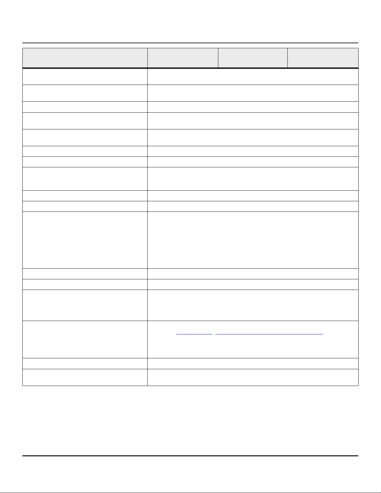
* Default configuration is 512E for 512E / 4KN drives.
See
Section 2.2.1 to Fast Format to 4KN in seconds
100835941, Rev. C
November 2018
Document Revision History
Revision Date Pages affected and Description of changes
Rev. A 06/06/2018 Initial release.
Rev. B 09/26/2018
11: Added Power-on note
25: Revised Table 7: Taiwan - Restricted Substances to latest BSMI requirements
Rev. C 11/12/2018 12-14: Updated Tables 6-8 (14TB, 12TB & 10TB) drive DC power requirements
7-8 & 18: Added cross reference to rated MTBF device operating condition requirements
© 2018 Seagate Technology LLC. All rights reserved.
Publication number: 100835941, Rev. C November 2018
Seagate, Seagate Technology and the Spiral logo are registered trademarks of Seagate Technology LLC in the United States and/or other countries. Raid Rebuild and SeaTools are either
trademarks or registered trademarks of Seagate Technology LLC or one of its affiliated companies in the United States and/or other countries. The FIPS logo is a certification mark of NIST,
which does not imply product endorsement by NIST, the U.S., or Canadian governments.All other trademarks or registered trademarks are the property of their respective owners.
No part of this publication may be reproduced in any form without written permission of Seagate Technology LLC.
Call 877-PUB-TEK1 (877-782-8351) to request permission.
When referring to drive capacity, one gigabyte, or GB, equals one billion bytes and one terabyte, or TB, equals one trillion bytes. Your computer’s operating system may use a different
standard of measurement and report a lower capacity. In addition, some of the listed capacity is used for formatting and other functions, and thus will not be available for data storage.
Actual quantities will vary based on various factors, including file size, file format, features and application software. Actual data rates may vary depending on operating environment
and other factors. The export or re-export of hardware or software containing encryption may be regulated by the U.S. Department of Commerce, Bureau of Industry and Security (for
more information, visit www.bis.doc.gov), and controlled for import and use outside of the U.S. Seagate reserves the right to change, without notice, product offerings or specifications.

Contents
Seagate® Technology Support Services . . . . . . . . . . . . . . . . . . . . . . . . . . . . . . . . . . . . . . . . . . . . . . . . . . . . . . . . . . . . . . . 4
1.0 Introduction . . . . . . . . . . . . . . . . . . . . . . . . . . . . . . . . . . . . . . . . . . . . . . . . . . . . . . . . . . . . . . . . . . . . . . . . . . . . . . . . . 5
1.1 About the Serial ATA interface . . . . . . . . . . . . . . . . . . . . . . . . . . . . . . . . . . . . . . . . . . . . . . . . . . . . . . . . . . . . . . . . 6
2.0 Drive specifications . . . . . . . . . . . . . . . . . . . . . . . . . . . . . . . . . . . . . . . . . . . . . . . . . . . . . . . . . . . . . . . . . . . . . . . . . . 7
2.1 Specification summary tables . . . . . . . . . . . . . . . . . . . . . . . . . . . . . . . . . . . . . . . . . . . . . . . . . . . . . . . . . . . . . . . . . 7
2.2 Formatted capacity . . . . . . . . . . . . . . . . . . . . . . . . . . . . . . . . . . . . . . . . . . . . . . . . . . . . . . . . . . . . . . . . . . . . . . . . . . 9
2.2.1 Fast Format - logical sector size conversion. . . . . . . . . . . . . . . . . . . . . . . . . . . . . . . . . . . . . . . . . . 9
2.2.2 LBA mode. . . . . . . . . . . . . . . . . . . . . . . . . . . . . . . . . . . . . . . . . . . . . . . . . . . . . . . . . . . . . . . . . . . . . . . . . 11
2.3 Recording and interface technology . . . . . . . . . . . . . . . . . . . . . . . . . . . . . . . . . . . . . . . . . . . . . . . . . . . . . . . . . 11
2.4 Start/stop times . . . . . . . . . . . . . . . . . . . . . . . . . . . . . . . . . . . . . . . . . . . . . . . . . . . . . . . . . . . . . . . . . . . . . . . . . . . . . 11
2.5 Power specifications . . . . . . . . . . . . . . . . . . . . . . . . . . . . . . . . . . . . . . . . . . . . . . . . . . . . . . . . . . . . . . . . . . . . . . . . . 12
2.5.1 Power consumption . . . . . . . . . . . . . . . . . . . . . . . . . . . . . . . . . . . . . . . . . . . . . . . . . . . . . . . . . . . . . . . 12
2.5.2 Conducted noise . . . . . . . . . . . . . . . . . . . . . . . . . . . . . . . . . . . . . . . . . . . . . . . . . . . . . . . . . . . . . . . . . . 16
2.5.3 Voltage tolerance . . . . . . . . . . . . . . . . . . . . . . . . . . . . . . . . . . . . . . . . . . . . . . . . . . . . . . . . . . . . . . . . . 16
2.5.4 Extended Power Conditions - PowerChoice™ . . . . . . . . . . . . . . . . . . . . . . . . . . . . . . . . . . . . . . . 16
2.6 Environmental limits. . . . . . . . . . . . . . . . . . . . . . . . . . . . . . . . . . . . . . . . . . . . . . . . . . . . . . . . . . . . . . . . . . . . . . . . . 18
2.6.1 Temperature . . . . . . . . . . . . . . . . . . . . . . . . . . . . . . . . . . . . . . . . . . . . . . . . . . . . . . . . . . . . . . . . . . . . . . 18
2.6.2 Humidity. . . . . . . . . . . . . . . . . . . . . . . . . . . . . . . . . . . . . . . . . . . . . . . . . . . . . . . . . . . . . . . . . . . . . . . . . . 18
2.6.3 Effective Altitude (sea level) . . . . . . . . . . . . . . . . . . . . . . . . . . . . . . . . . . . . . . . . . . . . . . . . . . . . . . . 18
2.6.4 Shock . . . . . . . . . . . . . . . . . . . . . . . . . . . . . . . . . . . . . . . . . . . . . . . . . . . . . . . . . . . . . . . . . . . . . . . . . . . . . 19
2.6.5 Vibration. . . . . . . . . . . . . . . . . . . . . . . . . . . . . . . . . . . . . . . . . . . . . . . . . . . . . . . . . . . . . . . . . . . . . . . . . . 19
2.7 Acoustics. . . . . . . . . . . . . . . . . . . . . . . . . . . . . . . . . . . . . . . . . . . . . . . . . . . . . . . . . . . . . . . . . . . . . . . . . . . . . . . . . . . . 20
2.8 Test for Prominent Discrete Tones (PDTs). . . . . . . . . . . . . . . . . . . . . . . . . . . . . . . . . . . . . . . . . . . . . . . . . . . . . 20
2.9 Electromagnetic immunity . . . . . . . . . . . . . . . . . . . . . . . . . . . . . . . . . . . . . . . . . . . . . . . . . . . . . . . . . . . . . . . . . . . 20
2.10 Reliability . . . . . . . . . . . . . . . . . . . . . . . . . . . . . . . . . . . . . . . . . . . . . . . . . . . . . . . . . . . . . . . . . . . . . . . . . . . . . . . . . . . 21
2.10.1 Annualized Failure Rate (AFR) and Mean Time Between Failures (MTBF) . . . . . . . . . . . . . 21
2.11 Agency and Safety Certifications . . . . . . . . . . . . . . . . . . . . . . . . . . . . . . . . . . . . . . . . . . . . . . . . . . . . . . . . . . . . . 21
2.11.1 Safety certification . . . . . . . . . . . . . . . . . . . . . . . . . . . . . . . . . . . . . . . . . . . . . . . . . . . . . . . . . . . . . . . . 21
2.11.2 Regulatory Models . . . . . . . . . . . . . . . . . . . . . . . . . . . . . . . . . . . . . . . . . . . . . . . . . . . . . . . . . . . . . . . . 21
2.11.3 European Union (EU) CE Marking Requirements . . . . . . . . . . . . . . . . . . . . . . . . . . . . . . . . . . . . 22
2.11.4 Australian RCM Compliance Mark . . . . . . . . . . . . . . . . . . . . . . . . . . . . . . . . . . . . . . . . . . . . . . . . . . 22
2.11.5 Canada ICES-003 . . . . . . . . . . . . . . . . . . . . . . . . . . . . . . . . . . . . . . . . . . . . . . . . . . . . . . . . . . . . . . . . . . 22
2.11.6 South Korean KC Certification Mark . . . . . . . . . . . . . . . . . . . . . . . . . . . . . . . . . . . . . . . . . . . . . . . . 22
2.11.7 Morocco Commodity Mark . . . . . . . . . . . . . . . . . . . . . . . . . . . . . . . . . . . . . . . . . . . . . . . . . . . . . . . . 22
2.11.8 Taiwanese BSMI . . . . . . . . . . . . . . . . . . . . . . . . . . . . . . . . . . . . . . . . . . . . . . . . . . . . . . . . . . . . . . . . . . . 23
2.11.9 FCC verification . . . . . . . . . . . . . . . . . . . . . . . . . . . . . . . . . . . . . . . . . . . . . . . . . . . . . . . . . . . . . . . . . . . 23
2.12 Environmental protection. . . . . . . . . . . . . . . . . . . . . . . . . . . . . . . . . . . . . . . . . . . . . . . . . . . . . . . . . . . . . . . . . . . . 23
2.12.1 European Union Restriction of Hazardous Substance Law. . . . . . . . . . . . . . . . . . . . . . . . . . . 23
2.12.2 China Requirements —China RoHS 2 . . . . . . . . . . . . . . . . . . . . . . . . . . . . . . . . . . . . . . . . . . . . . . 24
2.12.3 Taiwan Requirements — Taiwan RoHS . . . . . . . . . . . . . . . . . . . . . . . . . . . . . . . . . . . . . . . . . . . . . 24
2.13 Corrosive environment . . . . . . . . . . . . . . . . . . . . . . . . . . . . . . . . . . . . . . . . . . . . . . . . . . . . . . . . . . . . . . . . . . . . . . 25
2.14 Reference documents . . . . . . . . . . . . . . . . . . . . . . . . . . . . . . . . . . . . . . . . . . . . . . . . . . . . . . . . . . . . . . . . . . . . . . . 26
2.15 Product warranty . . . . . . . . . . . . . . . . . . . . . . . . . . . . . . . . . . . . . . . . . . . . . . . . . . . . . . . . . . . . . . . . . . . . . . . . . . . . 26
Seagate Exos X14 SATA Product Manual, Rev. C 2

Contents
3.0 Configuring and mounting the drive . . . . . . . . . . . . . . . . . . . . . . . . . . . . . . . . . . . . . . . . . . . . . . . . . . . . . . . . . 27
3.1 Handling and static-discharge precautions . . . . . . . . . . . . . . . . . . . . . . . . . . . . . . . . . . . . . . . . . . . . . . . . . . . 27
3.2 Configuring the drive . . . . . . . . . . . . . . . . . . . . . . . . . . . . . . . . . . . . . . . . . . . . . . . . . . . . . . . . . . . . . . . . . . . . . . . . 27
3.3 Serial ATA cables and connectors . . . . . . . . . . . . . . . . . . . . . . . . . . . . . . . . . . . . . . . . . . . . . . . . . . . . . . . . . . . . 27
3.4 Drive mounting . . . . . . . . . . . . . . . . . . . . . . . . . . . . . . . . . . . . . . . . . . . . . . . . . . . . . . . . . . . . . . . . . . . . . . . . . . . . . 28
3.4.1 Mechanical specifications . . . . . . . . . . . . . . . . . . . . . . . . . . . . . . . . . . . . . . . . . . . . . . . . . . . . . . . . . 28
4.0 About self-encrypting drives. . . . . . . . . . . . . . . . . . . . . . . . . . . . . . . . . . . . . . . . . . . . . . . . . . . . . . . . . . . . . . . . . 29
4.1 Data encryption . . . . . . . . . . . . . . . . . . . . . . . . . . . . . . . . . . . . . . . . . . . . . . . . . . . . . . . . . . . . . . . . . . . . . . . . . . . . . 29
4.2 Controlled access . . . . . . . . . . . . . . . . . . . . . . . . . . . . . . . . . . . . . . . . . . . . . . . . . . . . . . . . . . . . . . . . . . . . . . . . . . . . 29
4.2.1 Admin SP . . . . . . . . . . . . . . . . . . . . . . . . . . . . . . . . . . . . . . . . . . . . . . . . . . . . . . . . . . . . . . . . . . . . . . . . . 29
4.2.2 Locking SP . . . . . . . . . . . . . . . . . . . . . . . . . . . . . . . . . . . . . . . . . . . . . . . . . . . . . . . . . . . . . . . . . . . . . . . . 29
4.2.3 Default password . . . . . . . . . . . . . . . . . . . . . . . . . . . . . . . . . . . . . . . . . . . . . . . . . . . . . . . . . . . . . . . . . 29
4.3 Random number generator (RNG). . . . . . . . . . . . . . . . . . . . . . . . . . . . . . . . . . . . . . . . . . . . . . . . . . . . . . . . . . . . 30
4.4 Drive locking . . . . . . . . . . . . . . . . . . . . . . . . . . . . . . . . . . . . . . . . . . . . . . . . . . . . . . . . . . . . . . . . . . . . . . . . . . . . . . . . 30
4.5 Data bands . . . . . . . . . . . . . . . . . . . . . . . . . . . . . . . . . . . . . . . . . . . . . . . . . . . . . . . . . . . . . . . . . . . . . . . . . . . . . . . . . . 30
4.6 Cryptographic erase . . . . . . . . . . . . . . . . . . . . . . . . . . . . . . . . . . . . . . . . . . . . . . . . . . . . . . . . . . . . . . . . . . . . . . . . . 30
4.7 Authenticated firmware download . . . . . . . . . . . . . . . . . . . . . . . . . . . . . . . . . . . . . . . . . . . . . . . . . . . . . . . . . . . 30
4.8 Power requirements . . . . . . . . . . . . . . . . . . . . . . . . . . . . . . . . . . . . . . . . . . . . . . . . . . . . . . . . . . . . . . . . . . . . . . . . . 31
4.9 Supported commands . . . . . . . . . . . . . . . . . . . . . . . . . . . . . . . . . . . . . . . . . . . . . . . . . . . . . . . . . . . . . . . . . . . . . . . 31
4.10 RevertSP . . . . . . . . . . . . . . . . . . . . . . . . . . . . . . . . . . . . . . . . . . . . . . . . . . . . . . . . . . . . . . . . . . . . . . . . . . . . . . . . . . . . 31
4.11 ATA Security Erase Unit Command on SED SATA drives . . . . . . . . . . . . . . . . . . . . . . . . . . . . . . . . . . . . . . . 31
4.12 Sanitize Device - CRYPTO SCRAMBLE EXT . . . . . . . . . . . . . . . . . . . . . . . . . . . . . . . . . . . . . . . . . . . . . . . . . . . . . 31
5.0 Serial ATA (SATA) interface . . . . . . . . . . . . . . . . . . . . . . . . . . . . . . . . . . . . . . . . . . . . . . . . . . . . . . . . . . . . . . . . . . 32
5.1 Hot-Plug compatibility. . . . . . . . . . . . . . . . . . . . . . . . . . . . . . . . . . . . . . . . . . . . . . . . . . . . . . . . . . . . . . . . . . . . . . . 32
5.2 Serial ATA device plug connector pin definitions . . . . . . . . . . . . . . . . . . . . . . . . . . . . . . . . . . . . . . . . . . . . . 32
5.3 Supported ATA commands . . . . . . . . . . . . . . . . . . . . . . . . . . . . . . . . . . . . . . . . . . . . . . . . . . . . . . . . . . . . . . . . . . 33
5.3.1 Identify Device command . . . . . . . . . . . . . . . . . . . . . . . . . . . . . . . . . . . . . . . . . . . . . . . . . . . . . . . . . 36
5.3.2 Identify Device Data log . . . . . . . . . . . . . . . . . . . . . . . . . . . . . . . . . . . . . . . . . . . . . . . . . . . . . . . . . . . 40
5.3.3 Device Statistics log . . . . . . . . . . . . . . . . . . . . . . . . . . . . . . . . . . . . . . . . . . . . . . . . . . . . . . . . . . . . . . . 53
5.3.4 Set Features command . . . . . . . . . . . . . . . . . . . . . . . . . . . . . . . . . . . . . . . . . . . . . . . . . . . . . . . . . . . . 55
5.3.5 S.M.A.R.T. commands . . . . . . . . . . . . . . . . . . . . . . . . . . . . . . . . . . . . . . . . . . . . . . . . . . . . . . . . . . . . . . 56
Seagate Exos X14 SATA Product Manual, Rev. C 3

Seagate® Technology Support Services
For information regarding online support and services, visit: http://www.seagate.com/contacts/
For information regarding Warranty Support, visit: http://www.seagate.com/support/warranty-and-replacements/
For information regarding data recovery services, visit: http://www.seagate.com/services-software/recover/
For Seagate OEM, Distribution partner and reseller portals, visit: http://www.seagate.com/partners/
Seagate Exos X14 SATA Product Manual, Rev. C 4
www.seagate.com Introduction
1.0 Introduction
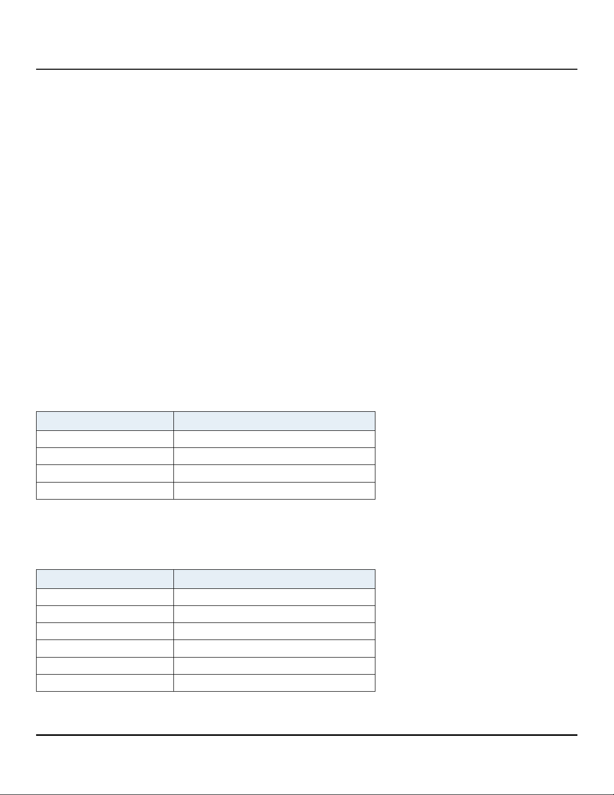
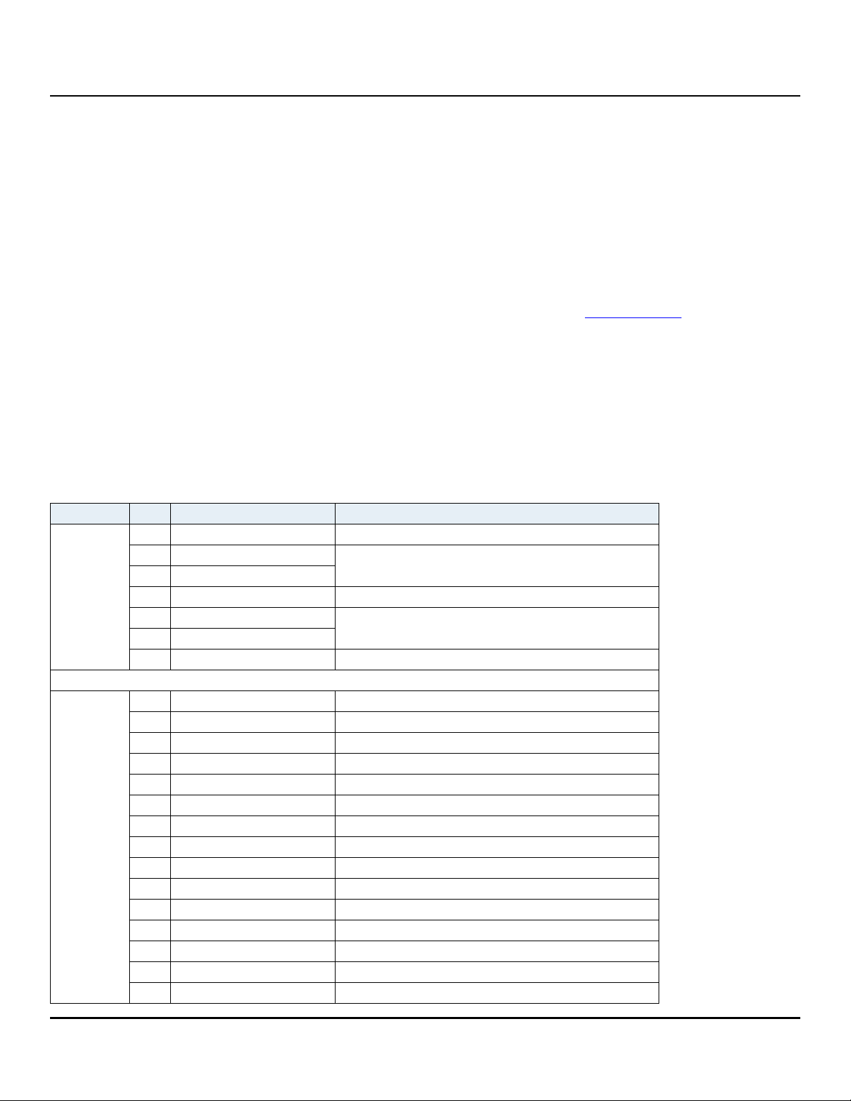
This manual describes the functional, mechanical and interface specifications for the following:
Seagate® Exos™ X14 SATA drive models.
Table 1: Models
Standard 512E models SED 512E models
ST14000NM0018
ST12000NM0008
ST10000NM0478
ST14000NM0258
ST12000NM0248
ST10000NM0568
These drives provide the following key features:
256 MB data buffer.
7200 RPM spindle speed.
Full-track multiple-sector transfer capability without local processor intervention.
High instantaneous (burst) data-transfer rates (up to 600MB per second).
Native Command Queuing with command ordering to increase performance in demanding applications.
PowerChoice™ for selectable power savings
Perpendicular recording technology provides the drives with increased areal density.
SeaTools™ diagnostic software performs a drive self-test that eliminates unnecessary drive returns.
State-of-the-art cache and on-the-fly error-correction algorithms.
Support for S.M.A.R.T. drive monitoring and reporting.
Supports latching SATA cables and connectors.
T13 Fast Format conversion (see Section 2.2.1)
Top Cover Attached motor for excellent vibration tolerance
Worldwide Name (WWN) capability uniquely identifies the drive.
NOTE Seagate recommends validating the configuration with the selected HBA/RAID
controller manufacturer to ensure use of full capacity is supported.
NOTE Previous generations of Seagate Self-Encrypting Drive models were called Full Disk
Encryption (FDE) models before a differentiation between drive-based encryption
and other forms of encryption was necessary.
NOTE The Self-Encrypting Drive models indicated on the cover of this product manual
have provisions for “Security of Data at Rest” based on the standards defined by the
Trusted Computing Group (see www.trustedcomputinggroup.org).
Seagate Exos X14 SATA Product Manual, Rev. C 5

www.seagate.com Introduction
1.1 About the Serial ATA interface
The Serial ATA interface provides several advantages over the traditional (parallel) ATA interface. The primary
advantages include:
Easy installation and configuration with true plug-and-play connectivity.
It is not necessary to set any jumpers or other configuration options.
Thinner and more flexible cabling for improved enclosure airflow and ease of installation.
Scalability to higher performance levels.
In addition, Serial ATA makes the transition from parallel ATA easy by providing legacy software support. Serial ATA
was designed to allow users to install a Serial ATA host adapter and Serial ATA disk drive in the current system and
expect all of the existing applications to work as normal.
The Serial ATA interface connects each disk drive in a point-to-point configuration with the Serial ATA host adapter.
There is no master/slave relationship with Serial ATA devices like there is with parallel ATA. If two drives are attached
on one Serial ATA host adapter, the host operating system views the two devices as if they were both “masters” on two
separate ports. This essentially means both drives behave as if they are Device 0 (master) devices.
NOTE The host adapter may, optionally, emulate a master/slave environment to host software
where two devices on separate Serial ATA ports are represented to host software as a
Device 0 (master) and Device 1 (slave) accessed at the same set of host bus addresses. A
host adapter that emulates a master/slave environment manages two sets of shadow
registers. This is not a typical Serial ATA environment.
The Serial ATA host adapter and drive share the function of emulating parallel ATA device behavior to provide
backward compatibility with existing host systems and software. The Command and Control Block registers, PIO and
DMA data transfers, resets, and interrupts are all emulated.
The Serial ATA host adapter contains a set of registers that shadow the contents of the traditional device registers,
referred to as the Shadow Register Block. All Serial ATA devices behave like Device 0 devices. For additional
information about how Serial ATA emulates parallel ATA, refer to the “Serial ATA: High Speed Serialized AT Attachment”
specification. The specification can be downloaded from www.serialata.or
g.
Seagate Exos X14 SATA Product Manual, Rev. C 6
www.seagate.com Drive specifications
2.0 Drive specifications
Unless otherwise noted, all specifications are measured under ambient conditions, at 25°C, and nominal power. For
convenience, the phrases the drive and this drive are used throughout this manual to indicate the Exos X14 SATA drive
models.
2.1 Specification summary tables
The specifications listed in the following tables are for quick reference. For details on specification measurement or
definition, see the appropriate section of this manual.
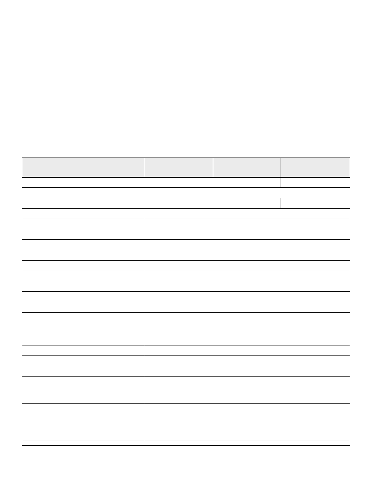
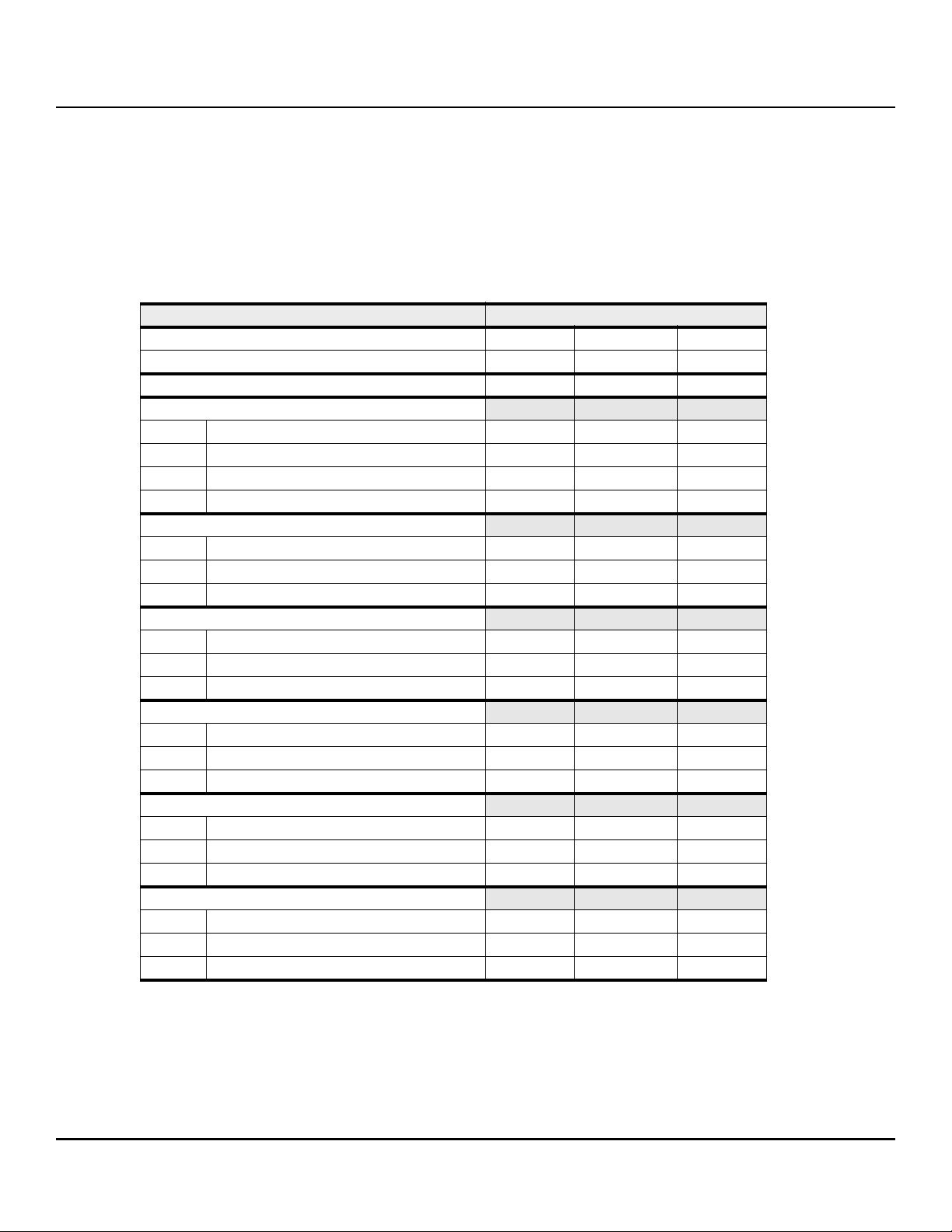
Table 2 Drive specifications summary
Drive specification
Formatted (512 bytes/sector)* 14TB 12TB 10TB
Guaranteed sectors (see Section 2.2)
Heads 16 15 13
Discs 8
Bytes per logical sector 512
Bytes per physical sector 4096
Recording density, KBPI (Kb/in max) 2426
Track density, KTPI (ktracks/in avg.) 436
Areal density, (Gb/in2 avg) 1058
Spindle speed (RPM) 7200
Internal data transfer rate (Mb/s max) 2833
Sustained data transfer rate OD (MiB/s max) 248 (261 MB/s max)
I/O data-transfer rate (MB/s max) 600
ATA data-transfer modes supported PIO modes 0–4
ST14000NM0018,
ST14000NM0258
Multiword DMA modes 0–2
Ultra DMA modes 0–6
ST12000NM0008,
ST12000NM0248
ST10000NM0478,
ST10000NM0568
Cache buffer 256MB (262,144KB)
Weight: (maximum) 690g (1.521 lb)
Average latency 4.16ms
Power-on to ready (sec) (typ/max) 20/30
Standby to ready (sec) (typ/max) 20/30
Startup current (typical) 12V (peak) 2.6A
2.0A (optional configuration through Smart Command Transport)
Voltage tolerance (including noise) 5V ± 5%
12V ± 10%
Operating temperature
Non-Operating temperature –40° to 70°C (Ambient Temperature, see sections 2.6.1 and 2.15)
Seagate Exos X14 SATA Product Manual, Rev. C 7
*
5° to 60°C (Drive Reported Temperature)
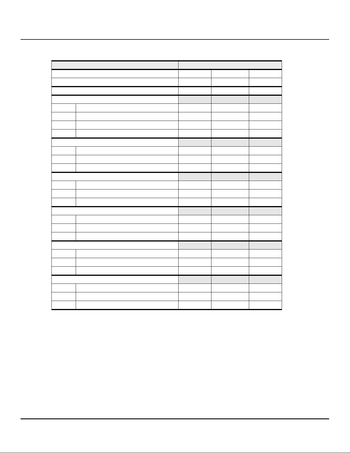
www.seagate.com Drive specifications
Drive specification
ST14000NM0018,
ST14000NM0258
ST12000NM0008,
ST12000NM0248
Temperature gradient (°C per hour max) 20°C (operating)
30°C (nonoperating)
Relative humidity
*
5% to 95% (operating)
5% to 95% (nonoperating)
Relative humidity gradient 30% per hour max
Altitude, operating –304.8 m to 3,048 m
(–1000 ft to 10,000+ ft)
Altitude, nonoperating (below mean sea level, max) –304.8 m to 12,192 m
(–1000 ft to 40,000+ ft)
Operational Shock (max at 2 ms - typical) Read 70 Gs / Write 40 Gs
Non-Operational Shock (max at 2 ms - typical) 250 Gs
Vibration, operating 5–22 Hz: 0.25 Gs, Limited displacement
22–350 Hz: 0.50 Gs
350–500 Hz: 0.25 Gs
Operation Rotational vibration 20–1500Hz: 12.5 rads/s²
Vibration, nonoperating 2–500 Hz: 2.27 Grms ref
Drive acoustics, sound power (bels)
Idle 2.8 (typical)
3.0 (max)
During periods of drive idle, some offline activity may occur according to the
SMART specification, which may increase acoustic and power to operational levels.
ST10000NM0478,
ST10000NM0568
Performance seek 3.2 (typical)
3.4 (max)
Nonrecoverable read errors 1 sector per 10
Annualized Failure Rate (AFR)
Maximum Rated Workload
*
*
0.35% based on 8760 POH
Maximum rate of <550TB/year
15
bits read
Workloads exceeding the annualized rate may degrade the drive MTBF and impact product reliability. The Annualized Workload Rate is in units of TB per year, or TB per 8760
power on hours. Workload Rate = TB transferred * (8760 / recorded power on hours).
Warranty To determine the warranty for a specific drive, use a web browser to access the following
web page: http://www.seagate.com/support/warranty-and-replacements/.
From this page, click on the “Is my Drive under Warranty” link. The following are required
to be provided: the drive serial number, model number (or part number) and country of
purchase.The system will display the warranty information for the drive.
Load-unload cycles 600,000
Supports Hotplug operation per
Yes
Serial ATA Revision 3.3 specification
*See Section 2.10, "Reliability" for rated MTBF device operating condition requirements.
Seagate Exos X14 SATA Product Manual, Rev. C 8
www.seagate.com Drive specifications
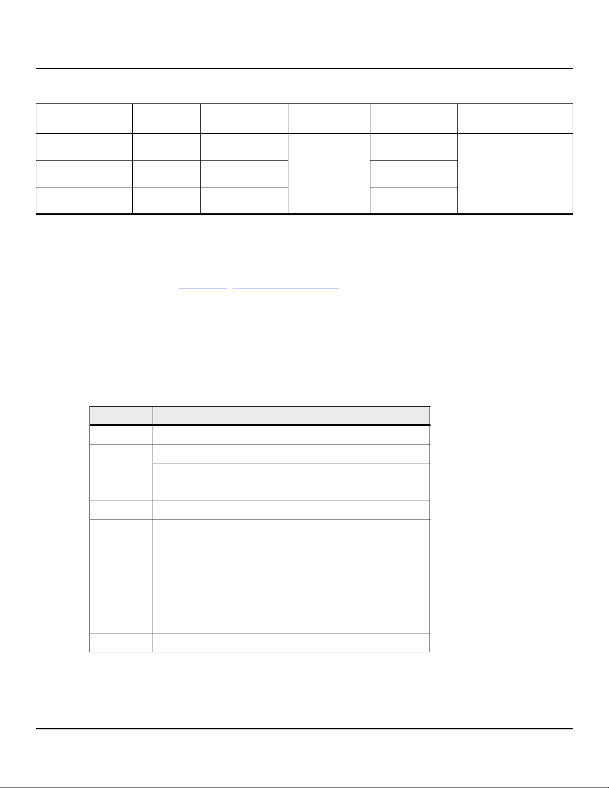
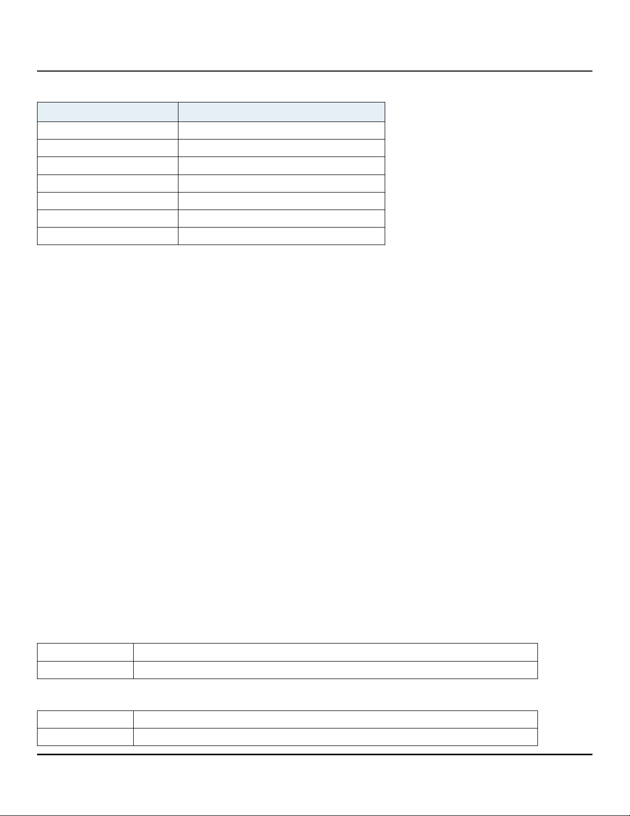
2.2 Formatted capacity
ST models
ST14000NM0018
ST14000NM0258
ST12000NM0008
ST12000NM0248
ST10000NM0478
ST10000NM0568
Formatted
capacity*
14TB 27,344,764,928
12TB 23,437,770,752 2,929,721,344
10TB 19,532,873,728 2,441,609,216
Guaranteed
sectors
Bytes per
logical sector
512
(Default)
Guaranteed
sectors
3,418,095,616
*One GB equals one billion bytes when referring to hard drive capacity. Accessible capacity may vary
depending on operating environment and formatting.
NOTE LBA Counts for drive capacities greater than 8TB are
calculated based upon the SFF-8447 standard publication.
ftp://ftp.seagate.com/sff/SFF-8447.PDF
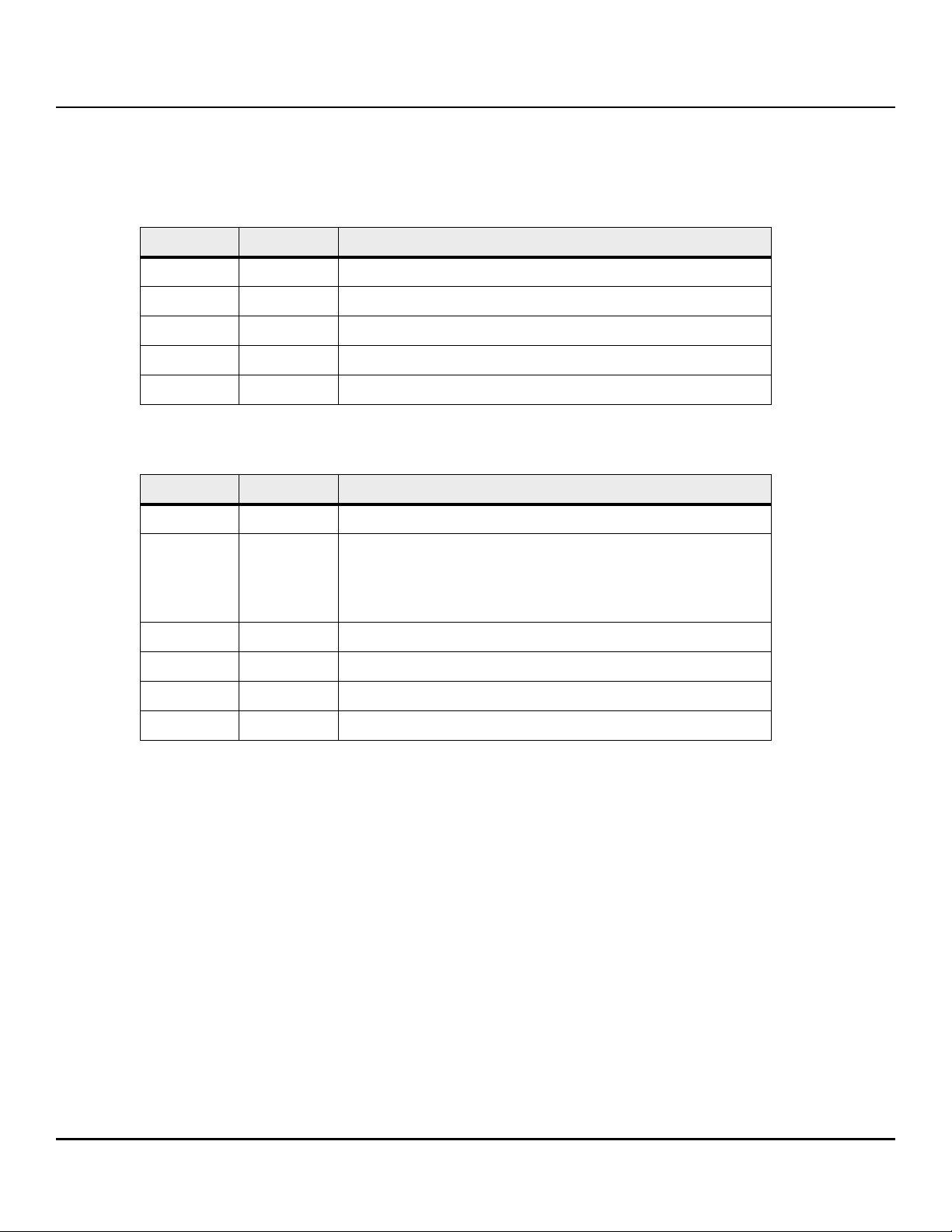
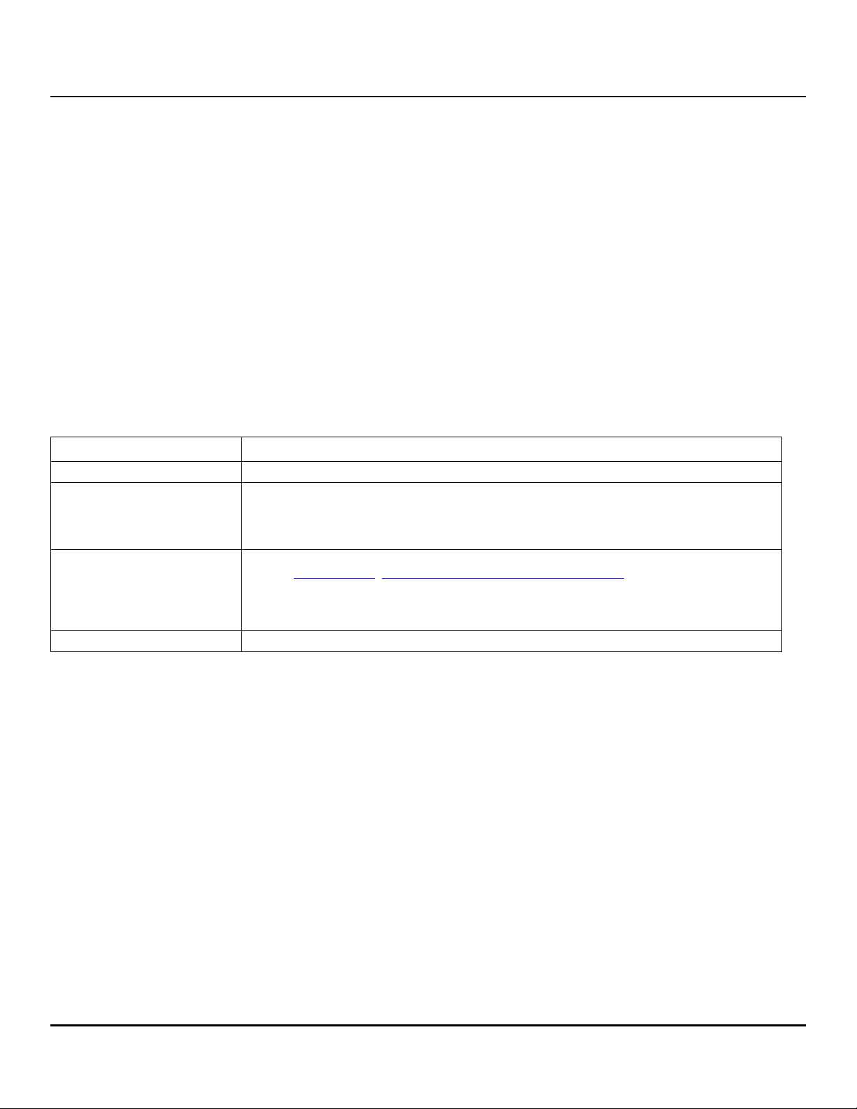
2.2.1 Fast Format - logical sector size conversion
Drive supports either 512E or 4KN logical sector size formats
SET SECTOR CONFIGURATION EXT (B2h) command (ACS-4 Standard) quickly converts between 512 and 4096 byte logical
sector size formats
The selected sector size change occurs immediately upon command completion
Default shipping format is 512E
Table 3 SET SECTOR CONFIGURATION EXT command inputs
Bytes per
logical sector
4096
(see Section 2.2.1)
Field Description
FEATURE COMMAND CHECK field
COUNT Bit Description
15 : 3 Reserved
2:0 SECTOR CONFIGURATION DESCRIPTOR INDEX field
LBA Reserved
DEVICE Bit Description
7 Obsolete
6 N/A
5 Obsolete
4 Transport Dependent
3:0 Reserved
COMMAND 7:0 B2h
COMMAND CHECK field value is taken from the DESCRIPTOR CHECK field in the descriptor specified by the
SECTOR CONFIGURATION DESCRIPTOR INDEX field
SECTOR CONFIGURATION DESCRIPTOR INDEX field specifies the Sector Configuration descriptor in the Set Sector
Configuration log page
Seagate Exos X14 SATA Product Manual, Rev. C 9
www.seagate.com Drive specifications
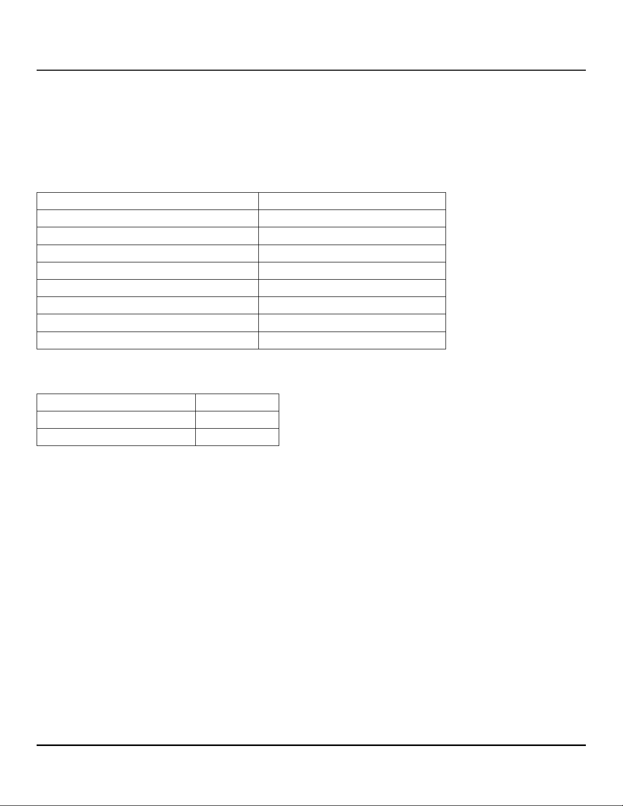
Sector Configuration log (Log Address 2Fh)
The Sector Configuration log contains Sector Configuration descriptors. The Sector Configuration descriptors describe
sector configurations. The sector configuration is specified using the SET SECTOR CONFIGURATION EXT command.
Table 4 Sector Configuration descriptors page format (log page 00h)
Offset Typ e Description
0...15 Bytes Sector Configuration descriptor 0
16...31 Bytes Sector Configuration descriptor 1
... ... ...
112...127 Bytes Sector Configuration descriptor 7
128...511 Bytes Reserved
Table 5 Sector Configuration descriptors format
Offset Typ e Description
0 Byte Sector Configuration descriptor flags
Bit Description
7 DESCRIPTOR VALID bit
6:0 Reserved
1 Byte LOGICAL TO PHYSICAL SECTOR RELATIONSHIP SETTING field
2...3 Word DESCRIPTOR CHECK field
4...7 DWord LOGICAL SECTOR SIZE SETTING field
8...15 Bytes Reserved
Seagate Exos X14 SATA Product Manual, Rev. C 10
www.seagate.com Drive specifications
2.2.2 LBA mode
When addressing these drives in LBA mode, all blocks (sectors) are consecutively numbered from 0 to n–1, where n is
the number of guaranteed sectors as defined above.
See Section 5.3.1, "Identify Device command" (words 60-61 and 100-103) for additional information about 48-bit
addressing support of drives with capacities over 137GB.
2.3 Recording and interface technology
Interface Serial ATA (SATA)
Recording method Perpendicular
Recording density, KBPI (Kb/in max) 2426
Track density, KTPI (ktracks/in avg) 436
Areal density (Gb/in2 avg) 1058
Spindle speed (RPM) (± 0.2%) 7200
Internal data transfer rate (Mb/s max) 2833
Sustained data transfer rate (MiB/s max) 248
I/O data-transfer rate (MB/s max) 600 (Ultra DMA mode 5)
2.4 Start/stop times
Power-on to Ready (sec) (typ/max) 20/30
Standby to Ready (sec) (typ/max) 20/30
Ready to spindle stop (sec) (max) 20
NOTE Power-on to ready time is based on typical operating conditions, and default
full current spin-up profile.
Seagate Exos X14 SATA Product Manual, Rev. C 11
www.seagate.com Drive specifications
2.5 Power specifications
The drive receives DC power (+5V or +12V) through a native SATA power connector. See Figure 2 on page 27 .
2.5.1 Power consumption
Power requirements for the drives are listed in Table 6. Typical power measurements are based on an average of
drives tested, under nominal conditions, using 5.0V and 12.0V input voltage at 25°C ambient temperature..
Table 6 DC power requirements (14TB)
6.0Gb mode
Voltage +5V +12V Watts
Regulation ± 5% ± 10% Total
Avg Idle Current * 0.26 0.31 5.00
Advanced Idle Current *
Idle_A 0.26 0.31 4.99
Idle_B 0.20 0.19 3.27
Idle_C 0.19 0.13 2.54
Standby 0.19 0.02 1.19
Maximum Start Current
DC (peak DC) 0.91 1.75 25.55
AC (Peak DC) 1.06 2.47
Delayed motor start (max) DC 0.26 0.06
Operating current (random read 4K16Q):
Typical DC 0.45 0.65 10.04
Maximum DC 0.46 0.66
Maximum DC (peak) 1.26 2.31
Operating current (random write 4K16Q)
Typical DC 0.34 0.36 5.99
Maximum DC 0.35 0.36
Maximum DC (peak) 0.78 2.15
Operating current (sequential read 64K16Q)
Typical DC 0.86 0.33 8.29
Maximum DC 0.89 0.34
Maximum DC (peak) 1.18 1.82
Operating current (sequential write 64K16Q)
Typical DC 0.70 0.33 7.43
Maximum DC 0.73 0.33
Maximum DC (peak) 0.85 0.58
*During periods of drive idle, some offline activity may occur according to the S.M.A.R.T. specification,
which may increase acoustic and power to operational levels.
Seagate Exos X14 SATA Product Manual, Rev. C 12
www.seagate.com Drive specifications
Table 7 DC power requirements (12TB)
6.0Gb mode
Voltage +5V +12V Watts
Regulation ± 5% ± 10% Total
Avg Idle Current * 0.25 0.30 4.91
Advanced Idle Current *
Idle_A 0.25 0.30 4.92
Idle_B 0.19 0.19 3.23
Idle_C 0.19 0.13 2.50
Standby 0.18 0.02 1.11
Maximum Start Current
DC (peak DC) 0.84 1.68 24.36
AC (Peak DC) 0.97 2.51
Delayed motor start (max) DC 0.26 0.06
Operating current (random read 4K16Q):
Typical DC 0.42 0.64 9.74
Maximum DC 0.43 0.64
Maximum DC (peak) 1.25 2.23
Operating current (random write 4K16Q)
Typical DC 0.33 0.35 5.84
Maximum DC 0.33 0.36
Maximum DC (peak) 0.77 2.12
Operating current (sequential read 64K16Q)
Typical DC 0.78 0.32 7.76
Maximum DC 0.81 0.33
Maximum DC (peak) 1.05 1.22
Operating current (sequential write 64K16Q)
Typical DC 0.68 0.32 7.22
Maximum DC 0.69 0.32
Maximum DC (peak) 0.82 0.85
*During periods of drive idle, some offline activity may occur according to the S.M.A.R.T. specification,
which may increase acoustic and power to operational levels.
Seagate Exos X14 SATA Product Manual, Rev. C 13

www.seagate.com Drive specifications
Table 8 DC power requirements (10TB)
6.0Gb mode
Voltage +5V +12V Watts
Regulation ± 5% ± 10% Total
Avg Idle Current * 0.27 0.29 4.87
Advanced Idle Current *
Idle_A 0.27 0.30 4.91
Idle_B 0.21 0.19 3.30
Idle_C 0.21 0.13 2.57
Standby 0.20 0.02 1.18
Maximum Start Current
DC (peak DC) 0.85 1.70 24.65
AC (Peak DC) 1.01 2.52
Delayed motor start (max) DC 0.26 0.06
Operating current (random read 4K16Q):
Typical DC 0.44 0.63 9.75
Maximum DC 0.45 0.64
Maximum DC (peak) 1.16 2.25
Operating current (random write 4K16Q)
Typical DC 0.35 0.34 5.83
Maximum DC 0.35 0.35
Maximum DC (peak) 0.82 2.13
Operating current (sequential read 64K16Q)
Typical DC 0.82 0.31 7.80
Maximum DC 0.84 0.32
Maximum DC (peak) 1.06 0.79
Operating current (sequential write 64K16Q)
Typical DC 0.70 0.31 7.17
Maximum DC 0.71 0.32
Maximum DC (peak) 0.86 0.79
*During periods of drive idle, some offline activity may occur according to the S.M.A.R.T. specification,
which may increase acoustic and power to operational levels.
Seagate Exos X14 SATA Product Manual, Rev. C 14
www.seagate.com Drive specifications
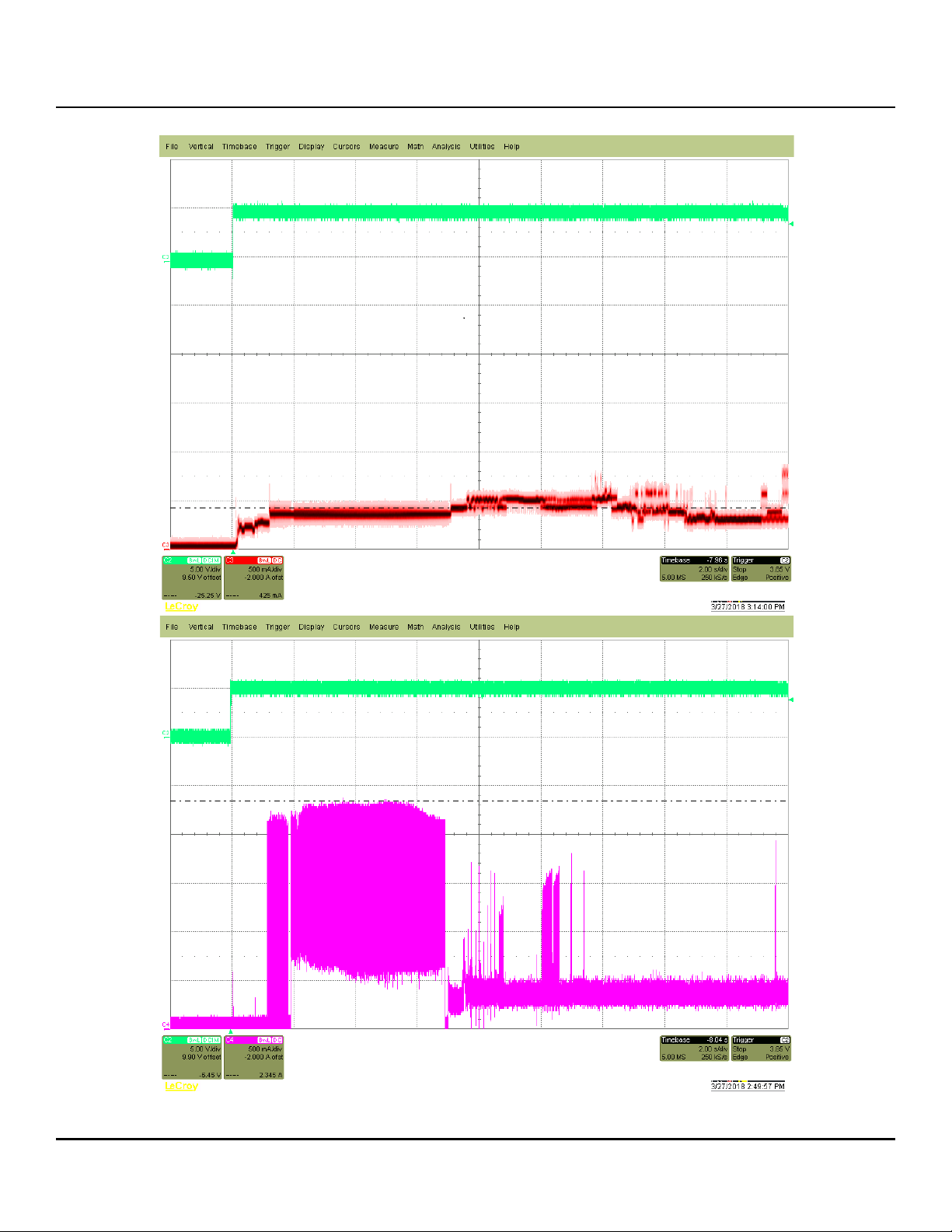
2.5.1.1 Typical current profiles
Figure 1. Typical 5V and 12V startup and operation current profiles
Seagate Exos X14 SATA Product Manual, Rev. C 15
www.seagate.com Drive specifications
2.5.2 Conducted noise
Noise is specified as a periodic and random distribution of frequencies covering a band from DC to 10 MHz. Maximum
allowed noise values given below are peak-to-peak measurements and apply at the drive power connector.
+5v = 250 mV pp from 100 Hz to 20 MHz.
+12v = 800 mV pp from 100 Hz to 8 KHz.
450 mV pp from 8 KHz to 20 KHz.
250 mV pp from 20 KHz to 5 MHz.
2.5.3 Voltage tolerance
Voltage tolerance (including noise):
5V ± 5% 12V ± 10%
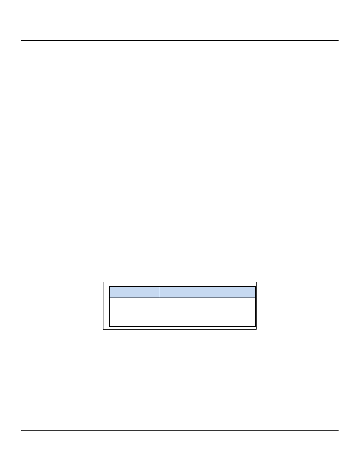
2.5.4 Extended Power Conditions - PowerChoice™
Utilizing the load/unload architecture a programmable power management interface is provided to tailor systems for
reduced power consumption and performance requirements.
The table below lists the supported power conditions available in PowerChoice. Power conditions are ordered from
highest power consumption (and shortest recovery time) to lowest power consumption (and longest recovery time)
as follows: Idle_a power >= Idle_b power >= Idle_c power >= Standby_z power. The further users go down in the
table, the more power savings is actualized. For example, Idle_b results in greater power savings than the Idle_a
power condition. Standby results in the greatest power savings.
Power Condition Name Power Condition ID Description
Idle_a 81
Idle_b 82
Idle_c 83
Standby_z 00
H
H
H
H
Reduced electronics
Heads unloaded. Disks spinning at full RPM
Heads unloaded. Disks spinning at reduced RPM
Heads unloaded. Motor stopped (disks not spinning)
Each power condition has a set of current, saved and default settings. Default settings are not modifiable. Default and
saved settings persist across power-on resets. The current settings do not persist across power-on resets. At the time
of manufacture, the default, saved and current settings are in the Power Conditions log match.
PowerChoice is invoked using one of two methods
Automatic power transitions which are triggered by expiration of individual power condition timers. These timer
values may be customized and enabled using the Extended Power Conditions (EPC) feature set using the
standardized Set Features command interface.
Immediate host commanded power transitions may be initiated using an EPC Set Features "Go to Power
Condition" subcommand to enter any supported power condition. Legacy power commands Standby Immediate
and Idle Immediate also provide a method to directly transition the drive into supported power conditions.
PowerChoice exits power saving states under the following conditions
Any command which requires the drive to enter the PM0: Active state (media access)
Power on reset
Seagate Exos X14 SATA Product Manual, Rev. C 16
www.seagate.com Drive specifications
PowerChoice provides the following reporting methods for tracking purposes
Check Power Mode Command
Reports the current power state of the drive
Identify Device Command
EPC Feature set supported flag
EPC Feature enabled flag is set if at least one Idle power condition timer is enabled
Power Condition Log reports the following for each power condition
Nominal recovery time from the power condition to active
If the power condition is Supported, Changeable, and Savable
Default enabled state, and timer value
Saved enabled state, and timer value
Current enabled state, and timer value
S.M.A.R.T. Read Data Reports
Attribute 192 - Emergency Retract Count
Attribute 193 - Load/Unload Cycle Count
PowerChoice Manufacture Default Power Condition Timer Values
Default power condition timer values have been established to assure product reliability and data integrity. A
minimum timer value threshold of two minutes ensures the appropriate amount of background drive maintenance
activities occur. Attempting to set a timer values less than the specified minimum timer value threshold will result in
an aborted EPC "Set Power Condition Timer" subcommand.
Power Condition Name Manufacturer Default Timer Values
Idle_a 100 ms
Idle_b 2 min
Idle_c 4 min
Standby_z 15 min
Setting power condition timer values less than the manufacturer specified defaults or issuing the EPC "Go to Power
Condition" subcommand at a rate exceeding the default timers may limit this products reliability and data integrity.
PowerChoice Supported Extended Power Condition Feature Subcommands
EPC Subcommand Description
00
01
02
03
04
05
H
H
H
H
H
H
Restore Power Condition Settings
Go to Power Condition
Set Power Condition Timer
Set Power Condition State
Enable EPC Feature Set
Disable EPC Feature Set
Seagate Exos X14 SATA Product Manual, Rev. C 17
www.seagate.com Drive specifications
PowerChoice Supported Extended Power Condition Identifiers
Power Condition Identifiers Power Condition Name
00
H
01 - 80
81
H
82
H
83
H
84 - FE
FF
H
H
H
Standby_z
Reserved
Idle_a
Idle_b
Idle_c
Reserved
All EPC Power Conditions
2.6 Environmental limits
Temperature and humidity values experienced by the drive must be such that condensation does not occur on any
drive part. Altitude and atmospheric pressure specifications are referenced to a standard day at 58.7°F (14.8°C).
NOTE To maintain optimal performance drives should be run at nominal drive
temperatures and humidity.
See Section 2.10, "Reliability" for rated MTBF device operating condition
requirements.
2.6.1 Temperature
a. Operating
41°F to 140°F (5°C to 60°C) temperature range with a maximum temperature gradient of 36°F (20°C) per hour as reported by the
drive.
The maximum allowable drive reported temperature is 140°F (60°C).
Air flow may be required to achieve consistent nominal drive temperature values (see Section 3.4). To confirm that the
required cooling is provided for the electronics and HDA, place the drive in its final mechanical configuration, and perform
random write/read operations. After the temperatures stabilize, monitor the current drive temperature using the SMART
temperature attribute 194 or Device Statistics log 04h page 5.
b. Non-operating
–40° to 158°F (–40° to 70°C) package ambient with a maximum gradient of 36°F (20°C) per hour. This specification assumes that
the drive is packaged in the shipping container designed by Seagate for use with drive.
2.6.2 Humidity
The values below assume that no condensation on the drive occurs. Maximum wet bulb temperature is 84.2°F (29°C).
2.6.2.1 Relative humidity
Operating: 5% to 95% non-condensing relative humidity with a maximum gradient of 20% per hour.
Nonoperating: 5% to 95% non-condensing relative humidity with a maximum gradient of 20% per hour.
2.6.3 Effective Altitude (sea level)
Operating: –304.8 m to 3048 m (–1000 ft. to 10,000+ ft.)
Nonoperating: –304.8 m to 12,192 m (–1000 ft. to 40,000+ ft.)
Seagate Exos X14 SATA Product Manual, Rev. C 18

www.seagate.com Drive specifications
2.6.4 Shock
All shock specifications assume that the drive is mounted securely with the input shock applied at the drive mounting
screws. Shock may be applied in the X, Y or Z axis.
2.6.4.1 Operating shock
These drives comply with the performance levels specified in this document when subjected to a maximum operating
shock of 70 Gs (read) and 40 Gs (write) based on half-sine shock pulses of 2ms. Shocks should not be repeated more
than two times per second.
2.6.4.2 Nonoperating shock
The nonoperating shock level that the drive can experience without incurring physical damage or degradation in
performance when subsequently put into operation is 250 Gs based on a nonrepetitive half-sine shock pulse of 2ms
duration.
2.6.5 Vibration
All vibration specifications assume that the drive is mounted securely with the input vibration applied at the drive
mounting screws. Vibration may be applied in the X, Y or Z axis.
2.6.5.1 Operating vibration
The maximum vibration levels that the drive may experience while meeting the performance standards specified in
this document are specified below.
5–22 Hz 0.25 Gs
22–350 Hz 0.50 Gs
350–500 Hz 0.25 Gs
20 - 1500Hz
*(RROV)
* Rotary Random Operating Vibration
12.5 rads/s2 w/RVFF
2.6.5.2 Nonoperating vibration
The maximum nonoperating vibration levels that the drive may experience without incurring physical damage or
degradation in performance when subsequently put into operation are specified below.
2–500 Hz
Linear Random
2.27 Grms ref
.
Freq (Hz) 2 4 100 500
2
G
/Hz .001 .03 .03 .001
Seagate Exos X14 SATA Product Manual, Rev. C 19

www.seagate.com Drive specifications
2.7 Acoustics
Drive acoustics are measured as overall A-weighted acoustic sound power levels (no pure tones). All measurements
are consistent with ISO document 7779. Sound power measurements are taken under essentially free-field conditions
over a reflecting plane. For all tests, the drive is oriented with the cover facing upward.
NOTE For seek mode tests, the drive is placed in seek mode only. The number of seeks
per second is defined by the following equation:
(Number of seeks per second = 0.4 / (average latency + average access time
)
Table 9 Fluid Dynamic Bearing (FDB) motor acoustics
Idle* Performance seek
All models 2.8 bels (typ)
3.0 bels (max)
*During periods of drive idle, some offline activity may occur according to the S.M.A.R.T. specification, which
may increase acoustic and power to operational levels.
3.2 bels (typ)
3.4 bels (max)
2.8 Test for Prominent Discrete Tones (PDTs)
Seagate follows the ECMA-74 standards for measurement and identification of PDTs. An exception to this process is
the use of the absolute threshold of hearing. Seagate uses this threshold curve (originated in ISO 389-7) to discern
tone audibility and to compensate for the inaudible components of sound prior to computation of tone ratios
according to Annex D of the ECMA-74 standards.
2.9 Electromagnetic immunity
When properly installed in a representative host system, the drive operates without errors or degradation in
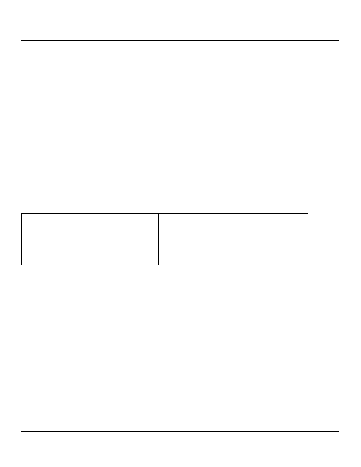
performance when subjected to the radio frequency (RF) environments defined in the following table:
Table 10 Radio frequency environments
Test Description Performance level Reference standard
Electrostatic discharge Contact, HCP, VCP: ± 4
Radiated RF immunity 80 to 1000 MHz, 3 V/m,
80% AM with 1 kHz sine
900 MHz, 3 V/m, 50% pulse modulation @ 200 Hz
kV; Air: ± 8 kV B EN 61000-4-2: 95
A EN 61000-4-3: 96
ENV 50204: 95
Electrical fast transient ± 1 kV on AC mains, ± 0.5 kV on external I/O B EN 61000-4-4: 95
Surge immunity ± 1 kV differential, ± 2 kV common, AC mains B EN 61000-4-5: 95
Conducted RF immunity 150 kHz to 80 MHz, 3 Vrms, 80% AM with 1 kHz sine A EN 61000-4-6: 97
Voltage dips, interrupts 0% open, 5 seconds
0% short, 5 seconds
40%, 0.10 seconds
70%, 0.01 seconds
Seagate Exos X14 SATA Product Manual, Rev. C 20
C
C
C
B
EN 61000-4-11: 94
www.seagate.com Drive specifications
2.10 Reliability
2.10.1 Annualized Failure Rate (AFR) and Mean Time Between Failures (MTBF)
The production disk drive shall achieve an annualized failure-rate of 0.35% (MTBF of 2,500,000 hours) over a 5 year
service life when used in Enterprise Storage field conditions as limited by the following:
8760 power-on hours per year.
HDA temperature as reported by the drive <= 30°C
Ambient wet bulb temp <= 26°C
Typical workload
The AFR (MTBF) is a population statistic not relevant to individual units
ANSI/ISA S71.04-2013 G2 classification levels and dust contamination to ISO 14644-1 Class 8 standards (as
measured at the device)
The MTBF specification for the drive assumes the operating environment is designed to maintain nominal drive
temperature and humidity. Occasional excursions in operating conditions between the rated MTBF conditions and
the maximum drive operating conditions may occur without significant impact to the rated MTBF. However continual
or sustained operation beyond the rated MTBF conditions will degrade the drive MTBF and reduce product reliability.
Nonrecoverable read errors
Load unload cycles 600,000 cycles
Maximum Rated Workload Maximum rate of <550TB/year
Warranty To determine the warranty for a specific drive, use a web browser to access the following web
Preventive maintenance None required.
1 per 10
Workloads exceeding the annualized rate may degrade the drive MTBF and impact product
reliability. The Annualized Workload Rate is in units of TB per year, or TB per 8760 power on hours.
Workload Rate = TB transferred * (8760 / recorded power on hours).
page: http://www.seagate.com/support/warranty-and-replacements/.
From this page, click on the “Is my Drive under Warranty” link. The following are required to be
provided: the drive serial number, model number (or part number) and country of purchase.The
system will display the warranty information for the drive.
15
bits read, max
2.11 Agency and Safety Certifications
Each Hard Drive and Solid State Drive ("drives") has a product label that includes certifications that are applicable to
that specific drive. The following information provides an overview of requirements that may be applicable to the
drive.
2.11.1 Safety certification
The drives are recognized in accordance with UL/cUL 62368 -1 and EN 62368 -1.
2.11.2 Regulatory Models
The following regulatory model number represent all features and configurations within the series:
Regulatory Model Numbers: STL006
Seagate Exos X14 SATA Product Manual, Rev. C 21
www.seagate.com Drive specifications
ࣗط یࡈ߇ΰח
%
ɼࢽࡈ؏ܞݦࢢ
ࢇ Е ɼࢽࡈ% ࢷળࢶଢԻ۰ ࣯Ի
ɼࢽ߾۰ یࡈଜЕ ʨࡶ ּࢶࡳԻ ଜֲ ֻҘ
ࠇ߾۰یࡈଟܹݡТЬ
2.11.3 European Union (EU) CE Marking Requirements
Drives that display the CE mark comply with the European Union (EU) requirements specified in the Electromagnetic
Compatibility Directive (2014/30/EU) put into force on 20 April 2016. Testing is performed to the levels specified by
the product standards for Information Technology Equipment (ITE). Emission levels are defined by EN 55032:2012,
Class B and the immunity levels are defined by EN 55024:2010.
The drives also meet the requirements of The Low Voltage Directive (LVD) 2014/35/EU.
Seagate drives are tested in representative end-user systems. Although CE-marked Seagate drives comply with all
relevant regulatory requirements and standards for the drives, Seagate cannot guarantee that all system-level
products into which the drives are installed comply with all regulatory requirements and standards applicable to the
system-level products. The drive is designed for operation inside a properly designed system (e.g., enclosure designed
for the drive), with properly shielded I/O cable (if necessary) and terminators on all unused I/O ports. Computer
manufacturers and system integrators should confirm EMC compliance and provide CE marking for the system-level
products.
For compliance with the RoHS "Recast" Directive 2011/65/EU (RoHS 2), See “European Union Restriction of Hazardous
Substance Law” on page 23.
2.11.4 Australian RCM Compliance Mark
If these models have the RCM marking, they comply with the Australia/New Zealand Standard AS/NZ CISPR32 and
meet the Electromagnetic Compatibility (EMC) Framework requirements of the Australian Communication and Media
Authority (ACMA).
2.11.5 Canada ICES-003
If this model has the ICES-003:2016 marking it complies with requirements of ICES tested per ANSI C63.4-2014.
2.11.6 South Korean KC Certification Mark
The South Korean KC Certification Mark means the drives comply with paragraph 1 of Article 11 of the
Electromagnetic Compatibility control Regulation and meet the Electromagnetic Compatibility (EMC) Framework
requirements of the Radio Research Agency (RRA) Communications Commission, Republic of Korea.These drives have
been tested and comply with the Electromagnetic Interference/Electromagnetic Susceptibility (EMI/EMS) for Class B
products. Drives are tested in a representative, end-user system by a Korean-recognized lab.
2.11.7 Morocco Commodity Mark
To satisfy our OEM customers, Seagate has added the Moroccan Commodity Mark to the drives provided to the OEM
for the sale of Customer Kits produced by our OEM customers that are intended to be incorporated into the OEM's
finished system-level product by an end user. The Customer Kits are considered 'devices' under Morocco's Order of the
Minister of Industry, Trade, Investment and Digital Economy No. 2574-14 of 29 Ramadan 1436 (16 July 2015) on
electromagnetic compatibility of equipment.
Seagate drives are tested for compliance and complies with the European Union (EU) Electromagnetic Compatibility
(EMC) Directive 2014/30/EU and the Low Voltage Directive (LVD) 2014/35/EU. Accordingly, the drives also meets the
requirements of Morocco's Order of the Minister of Industry, Trade, Investment and Digital Economy No. 2574-14 of 29
Ramadan 1436 (16 July 2015) on electromagnetic compatibility of equipment.
Seagate Exos X14 SATA Product Manual, Rev. C 22

www.seagate.com Drive specifications
2.11.8 Taiwanese BSMI
Drives with the Taiwanese certification mark comply with Chinese National Standard, CNS13438.
For compliance with the Taiwan Bureau of Standards, Metrology and Inspection’s (BSMI) requirements, See “Taiwan
Requirements — Taiwan RoHS” on page 24.
2.11.9 FCC verification
These drives are intended to be contained solely within a personal computer or similar enclosure (not attached as an
external device). As such, each drive is considered to be a subassembly even when it is individually marketed to the
customer. As a subassembly, no Federal Communications Commission verification or certification of the device is
required.
Seagate has tested this device in enclosures as described above to ensure that the total assembly (enclosure, disk
drive, motherboard, power supply, etc.) does comply with the limits for a Class B computing device, pursuant to
Subpart J, Part 15 of the FCC rules. Operation with noncertified assemblies is likely to result in interference to radio
and television reception.
Radio and television interference. This equipment generates and uses radio frequency energy and if not installed
and used in strict accordance with the manufacturer’s instructions, may cause interference to radio and television
reception.
This equipment is designed to provide reasonable protection against such interference in a residential installation.
However, there is no guarantee that interference will not occur in a particular installation. If this equipment does
cause interference to radio or television, which can be determined by turning the equipment on and off, users are
encouraged to try one or more of the following corrective measures:
Reorient the receiving antenna.
Move the device to one side or the other of the radio or TV.
Move the device farther away from the radio or TV.
Plug the computer into a different outlet so that the receiver and computer are on different branch outlets.
If necessary, users should consult a dealer or an experienced radio/television technician for additional suggestions.
Users may find helpful the following booklet prepared by the Federal Communications Commission: How to Identify
and Resolve Radio-Television Interference Problems. This booklet is available from the Superintendent of Documents,
U.S. Government Printing Office, Washington, DC 20402. Refer to publication number 004-000-00345-4.
2.12 Environmental protection
Seagate designs its products to meet environmental protection requirements worldwide, including regulations
restricting certain chemical substances.
2.12.1 European Union Restriction of Hazardous Substance Law
2.12.1.1 Restriction of Hazardous Substances in Electrical and Electronic Equipment
Seagate drives are designed to be compliant with the European Union RoHS "Recast" Directive 2011/65/EU (RoHS 2)
as amended by Directive (EU) 2015/863. The RoHS2 restricts the use of certain hazardous substances such as Lead,
Cadmium, Mercury, Hexavalent Chromium, Polybrominated Biphenyls (PBB) and Polybrominated Diphenyl Ether
(PBDE), BisBis(2-Ethylhexyl) phthalate (DEHP), Benzyl butyl phthalate (BBP), Dibutyl phthalate (DBP), and Diisobutyl
phthalate (DIBP) in electrical and electronic equipment (EEE).
Seagate Exos X14 SATA Product Manual, Rev. C 23
www.seagate.com Drive specifications
20
2.12.1.2 Substances of Very High Concern (SVHC)
The European Union REACH (Registration, Evaluation, Authorization and Restriction of Chemicals) Regulation (EC)
1907/2006 regulates chemicals shipped into and used in Europe. A number of parts and materials in Seagate products
are procured from external suppliers. We rely on the representations of our suppliers regarding the presence of REACH
substances in these articles and materials. Our supplier contracts require compliance with our chemical substance
restrictions, and our suppliers document their compliance with our requirements by providing full-disclosure material
content declarations that disclose inclusion of any REACH-regulated substance in such articles or materials. Productspecific REACH declarations are available upon request through your Seagate Sales Representative.
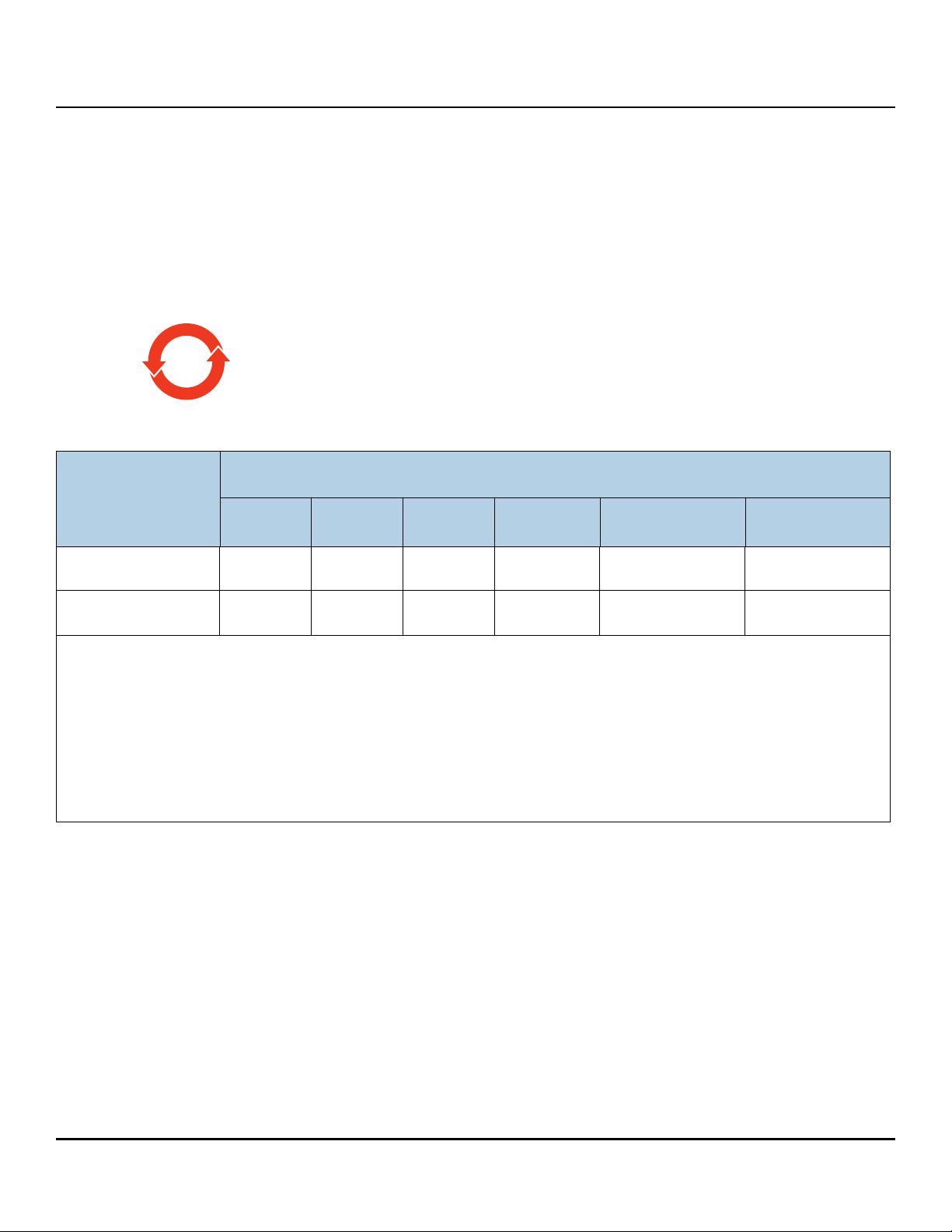
2.12.2 China Requirements —China RoHS 2
China RoHS 2 refers to the Ministry of Industry and Information Technology Order No. 32, effective July
1, 2016, titled Management Methods for the Restriction of the Use of Hazardous Substances in Electrical
and Electronic Products. To comply with China RoHS 2, Seagate determines this product's
Environmental Protection Use Period (EPUP) to be 20 years in accordance with the Marking for the
Restricted Use of Hazardous Substances in Electronic and Electrical Products, SJT 11364-2014.
Table 11 China - Hazardous Substances
有害物质
部件名称
Part Name
铅
(Pb)
汞
(Hg)
Hazardous Substances
镉
(Cd)
六价铬
(Cr+6)
多溴联苯
(PBB)
多溴二苯醚
(PBDE)
硬盘驱动器
HDD
印刷电路板组装
PCBA
本表格依据 SJ/T 11364 的规定编制。
This table is prepared in accordance with the provisions of SJ/T 11364-2014
O:表示该有害物质在该部件所有均质材料中的含量均在 GB/T 26572 规定的限量要求以下。
O:Indicates that the hazardous substance contained in all of the homogeneous materials for this
part is below the limit requirement of GB/T26572.
X:表示该有害物质至少在该部件的某一均质材料中的含量超出 GB/T 26572 规定的限量要求。
X:Indicates that the hazardous substance contained in at least one of the homogeneous materials
used for this part is above the limit requirement of GB/T26572.
2.12.3 Taiwan Requirements — Taiwan RoHS
Taiwan RoHS refers to the Taiwan Bureau of Standards, Metrology and Inspection’s (BSMI) requirements in standard
CNS 15663, Guidance to reduction of the restricted chemical substances in electrical and electronic equipment.
Seagate products must comply with the “Marking of presence” requirements in Section 5 of CNS 15663, effective
January 1, 2018. This product is Taiwan RoHS compliant.
XOO O O O
XOO O O O
Seagate Exos X14 SATA Product Manual, Rev. C 24
www.seagate.com Drive specifications
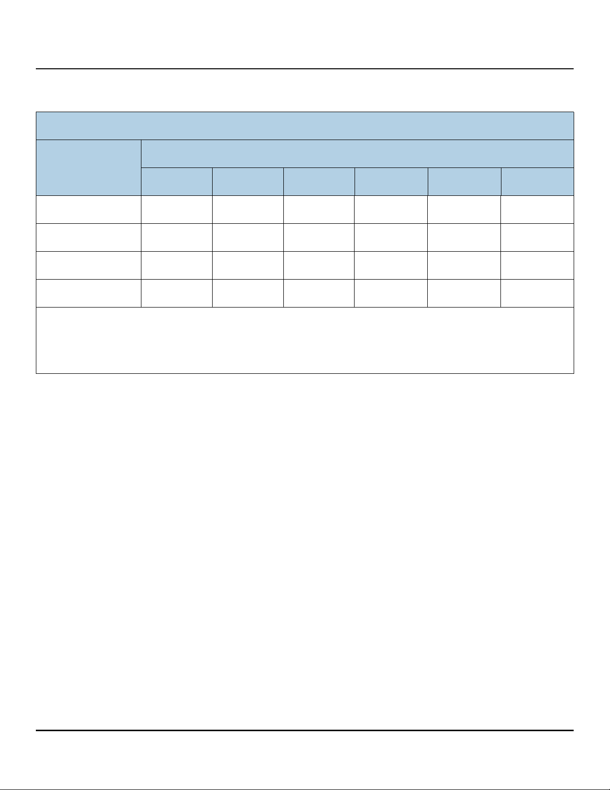
The following table meets the Section 5 “Marking of presence” requirements.
Table 12 Taiwan - Restricted Substances
設備名稱:硬碟設備,型號 :
Equipment Name: Hard Disk Device, Type Designation:
限用物質及其化學符號
單元
Unit
鉛
(Pb)
Restricted Substance and its chemical symbol
汞
(Hg)
鎘
(Cd)
六價鉻
(Cr+6)
多溴聯苯
(PBB)
多溴二苯醚
(PBDE)
頂蓋
Top Cover
磁碟
Magnetic disk
電機底座組件
Motor Base Assembly
印刷電路板组装
PCB Assembly
備考 1. "O" 係指該项限用物質之百分比含量未超出百分比含量基準值。
Note 1. "O" indicates that the percentage content of the restricted substance does not exceed the percentage of reference value of presence.
備考 2. "—" 係指該项限用物質為排除項目。
Note 2. "—" indicates that the restricted substance corresponds to the exemption.
—OOOOO
—OOOOO
—OOOOO
—OOOOO
2.13 Corrosive environment
Seagate electronic drive components pass accelerated corrosion testing equivalent to 10 years exposure to light
industrial environments containing sulfurous gases, chlorine and nitric oxide, classes G and H per ASTM B845.
However, this accelerated testing cannot duplicate every potential application environment.
Users should use caution exposing any electronic components to uncontrolled chemical pollutants and corrosive
chemicals as electronic drive component reliability can be affected by the installation environment. The silver, copper,
nickel and gold films used in hard disk drives are especially sensitive to the presence of sulfide, chloride, and nitrate
contaminants. Sulfur is found to be the most damaging. Materials used in cabinet fabrication, such as vulcanized
rubber, that can outgas corrosive compounds should be minimized or eliminated. The useful life of any electronic
equipment may be extended by replacing materials near circuitry with sulfide-free alternatives.
Seagate recommends that data centers be kept clean by monitoring and controlling the dust and gaseous
contamination. Gaseous contamination should be within ANSI/ISA S71.04-2013 G2 classification levels (as measured
on copper and silver coupons), and dust contamination to ISO 14644-1 Class 8 standards, and MTBF rated conditions
as defined in the Annualized Failure Rate (AFR) and Mean Time Between Failure (MTBF) section.
Seagate Exos X14 SATA Product Manual, Rev. C 25

www.seagate.com Drive specifications
2.14 Reference documents
Supported Standards
Serial ATA Revision 3.3 specification
ANSI Documents
INCITS 522-2014ATA/ATAPI Command Set - 3 (ACS-3)
Specification for Acoustic Test Requirement and Procedures
Seagate part number: 30553-001
In case of conflict between this document and any referenced document, this document takes precedence.
2.15 Product warranty
Beginning on the date of shipment to the customer and continuing for the period specified in the purchase contract,
Seagate warrants that each product (including components and subassemblies) that fails to function properly under
normal use due to defect in materials or workmanship or due to nonconformance to the applicable specifications will
be repaired or replaced, at Seagate’s option and at no charge to the customer, if returned by customer at customer’s
expense to Seagate’s designated facility in accordance with Seagate’s warranty procedure. Seagate will pay for
transporting the repair or replacement item to the customer. For more detailed warranty information, refer to the
standard terms and conditions of purchase for Seagate products on the purchase documentation.
The remaining warranty for a particular drive can be determined by calling Seagate Customer Service at 1-800-468-
3472. Users can also determine remaining warranty using the Seagate web site (www.sea
number is required to determine remaining warranty information.
Shipping
When transporting or shipping a drive, use only a Seagate-approved container. Keep the original box. Seagate
approved containers are easily identified by the Seagate Approved Package label. Shipping a drive in a non-approved
container voids the drive warranty.
Seagate repair centers may refuse receipt of components improperly packaged or obviously damaged in transit.
Contact the authorized Seagate distributor to purchase additional boxes. Seagate recommends shipping by an airride carrier experienced in handling computer equipment.
gate.com). The drive serial
Storage
Maximum storage periods are 180 days within original unopened Seagate shipping package or 60 days unpackaged
within the defined non-operating limits (refer to environmental section in this manual). Storage can be extended to 1
year packaged or unpackaged under optimal environmental conditions (25°C, <40% relative humidity noncondensing, and non-corrosive environment). During any storage period the drive non-operational temperature,
humidity, wet bulb, atmospheric conditions, shock, vibration, magnetic and electrical field specifications should be
followed.
Product repair and return information
Seagate customer service centers are the only facilities authorized to service Seagate drives. Seagate does not
sanction any third-party repair facilities. Any unauthorized repair or tampering with the factory seal voids the
warranty.
Seagate Exos X14 SATA Product Manual, Rev. C 26

www.seagate.com Configuring and mounting the drive
Power cable
Signal cable
Signal connector
Power connector
3.0 Configuring and mounting the drive
This section contains the specifications and instructions for configuring and mounting the drive.
3.1 Handling and static-discharge precautions
After unpacking, and before installation, the drive may be exposed to potential handling and electrostatic discharge
(ESD) hazards. Observe the following standard handling and static-discharge precautions:
• Before handling the drive, put on a grounded wrist strap, or ground oneself frequently by touching the metal chassis of a
computer that is plugged into a grounded outlet. Wear a grounded wrist strap throughout the entire installation procedure.
• Handle the drive by its edges or frame only.
Caution
3.2 Configuring the drive
• The drive is extremely fragile—handle it with care. Do not press down on the drive top cover.
• Always rest the drive on a padded, antistatic surface until mounting it in the computer.
• Do not touch the connector pins or the printed circuit board.
• Do not remove the factory-installed labels from the drive or cover them with additional labels. Removal voids the warranty. Some
factory-installed labels contain information needed to service the drive. Other labels are used to seal out dirt and contamination.
Each drive on the Serial ATA interface connects point-to-point with the Serial ATA host adapter. There is no master/
slave relationship because each drive is considered a master in a point-to-point relationship. If two drives are attached
on one Serial ATA host adapter, the host operating system views the two devices as if they were both “masters” on two
separate ports. Both drives behave as if they are Device 0 (master) devices.
3.3 Serial ATA cables and connectors
The Serial ATA interface cable consists of four conductors in two differential pairs, plus three ground connections. The
cable size may be 30 to 26 AWG with a maximum length of one meter (39.37 in).
Figure 2. Attaching SATA cabling
Each cable is keyed to ensure correct orientation. Exos X14 SATA drives support latching SATA connectors.
See Table 13 for connector pin definitions. Either end of the SATA
signal cable can be attached to the drive or host.
For direct backplane connection, the drive connectors are inserted
directly into the host receptacle. The drive and the host receptacle
incorporate features that enable the direct connection to be hot
pluggable and blind mateable.
For installations which require cables, users can connect the drive as
illustrated in Figure 2.
Seagate Exos X14 SATA Product Manual, Rev. C 27
www.seagate.com Configuring and mounting the drive
2X 1.625±.020
2X 3.000±.010
4.000±.010 LQ
1.432
.125±.010
3.750±.010
.814
2.000
4X 6-32 UNC 2B
3 MIN THREAD DEPTH
.14 MAX FASTENER PENETRATION
MOUNTING HOLE.
MAX TORQUE 6 IN/LBS
B
Y
.250±.010
5.787LQ MAX
146. MM
1.122±.020LQ
4.000±.010
1.638±.010
2X 6-32 UNC 2B
3 MIN THREAD DEPTH
.14 MAX FASTENER PENETRATION
MOUNTING HOLES BOTH SIDES.
MAX TORQUE 6 IN/LBS
Y
Z
1.028LQ MAX
26.11MM
.138 ±.015
2.000
C
L
OF DRIVE
C
L
OF DRIVE
C
L
OF CONN
Z
28.50 ±.51 mm
101.60 ±.25 mm
3.4 Drive mounting
Users can mount the drive in any orientation using four screws in the side-mounting holes or four screws in the
bottom-mounting holes. See Figure 3 for drive mounting dimensions. Follow these important mounting precautions
when mounting the drive:
Allow a minimum clearance of 0.030 in (0.76mm) around the entire perimeter of the drive for cooling.
Use only 6-32 UNC mounting screws.
The screws should be inserted no more than 0.140 in (3.56mm) into the bottom or side mounting holes.
Do not overtighten the mounting screws (maximum torque: 6 in-lb).
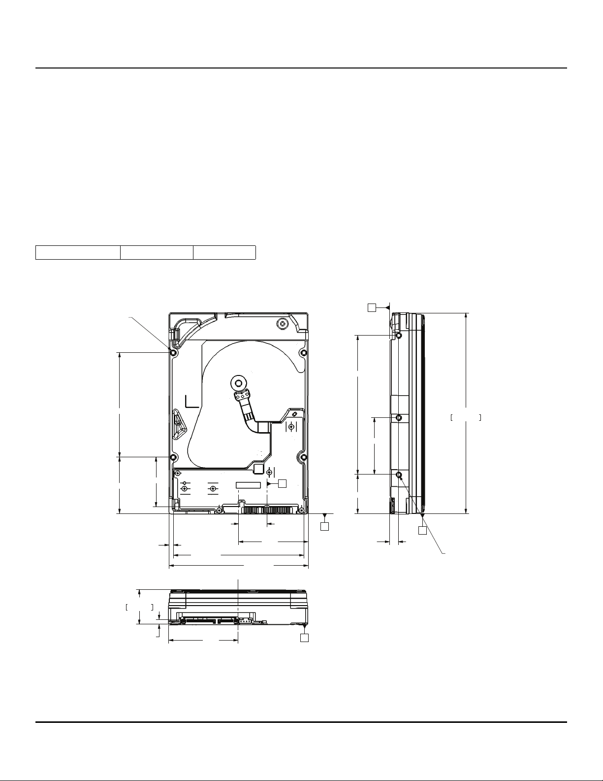
3.4.1 Mechanical specifications
Refer to Figure 3 for detailed mounting configuration dimensions. See Section 3.4, “Drive mounting.”
Weight: 1.521 lb 690 g
NOTE These dimensions conform to the Small Form Factor Standard documented in SFF-8301
and SFF-8323, found at www.snia.org/technology-communities/sff/specifications
Figure 3. Mounting configuration dimensions
NOTE The image is for mechanical dimension reference
only and may not represent the actual drive.
Seagate Exos X14 SATA Product Manual, Rev. C 28

www.seagate.com About self-encrypting drives
4.0 About self-encrypting drives
Self-encrypting drives (SEDs) offer encryption and security services for the protection of stored data, commonly
known as “protection of data at rest.” These drives are compliant with the Trusted Computing Group (TCG) Enterprise
Storage Specifications as detailed in Section 2.14.
The Trusted Computing Group (TCG) is an organization sponsored and operated by companies in the computer,
storage and digital communications industry. Seagate’s SED models comply with the standards published by the TCG.
To use the security features in the drive, the host must be capable of constructing and issuing the following two ATA
commands:
Trusted Send
Trusted Receive
These commands are used to convey the TCG protocol to and from the drive in their command payloads.
4.1 Data encryption
Encrypting drives use one inline encryption engine for each port, employing AES-256 bit data encryption keys with
AES-XTS mode to encrypt all data prior to being written on the media and to decrypt all data as it is read from the
media. The encryption engines are always in operation and cannot be disabled.
The 32-byte Data Encryption Key (DEK) is a random number which is generated by the drive, never leaves the drive,
and is inaccessible to the host system. The DEK is itself encrypted when it is stored on the media and when it is in
volatile temporary storage (DRAM) external to the encryption engine. A unique data encryption key is used for each of
the drive's possible16 data bands (see Section 4.5).
4.2 Controlled access
The drive has two security providers (SPs) called the "Admin SP" and the "Locking SP." These act as gatekeepers to the
drive security services. Security-related commands will not be accepted unless they also supply the correct credentials
to prove the requester is authorized to perform the command.
4.2.1 Admin SP
The Admin SP allows the drive's owner to enable or disable firmware download operations (see Section 4.4). Access to
the Admin SP is available using the SID (Secure ID) password or the MSID (Manufacturers Secure ID) password.
4.2.2 Locking SP
The Locking SP controls read/write access to the media and the cryptographic erase feature. Access to the Locking SP
is available using the BandMasterX or EraseMaster passwords. Since the drive owner can define up to 16 data bands
on the drive, each data band has its own password called BandMasterX where X is the number of the data band (0
through 15).
4.2.3 Default password
When the drive is shipped from the factory, all passwords are set to the value of MSID. This 32-byte random value can
only be read by the host electronically over the interface. After receipt of the drive, it is the responsibility of the owner
to use the default MSID password as the authority to change all other passwords to unique owner-specified values.
Seagate Exos X14 SATA Product Manual, Rev. C 29

www.seagate.com About self-encrypting drives
4.3 Random number generator (RNG)
The drive has a 32-byte hardware RNG that it is uses to derive encryption keys or, if requested to do so, to provide
random numbers to the host for system use, including using these numbers as Authentication Keys (passwords) for
the drive’s Admin and Locking SPs.
4.4 Drive locking
In addition to changing the passwords, as described in Section 4.2.3, the owner should also set the data access
controls for the individual bands.
The variable "LockOnReset" should be set to "PowerCycle" to ensure that the data bands will be locked if power is lost.
In addition "ReadLockEnabled" and "WriteLockEnabled" must be set to true in the locking table in order for the bands
"LockOnReset" setting of "PowerCycle" to actually lock access to the band when a "PowerCycle" event occurs. This
scenario occurs if the drive is removed from its cabinet. The drive will not honor any data read or write requests until
the bands have been unlocked. This prevents the user data from being accessed without the appropriate credentials
when the drive has been removed from its cabinet and installed in another system.
When the drive is shipped from the factory, the firmware download port is unlocked.
4.5 Data bands
When shipped from the factory, the drive is configured with a single data band called Band 0 (also known as the
Global Data Band) which comprises LBA 0 through LBA max. The host may allocate Band1 by specifying a start LBA
and an LBA range. The real estate for this band is taken from the Global Band. An additional 30 Data Bands may be
defined in a similar way (Band2 through Band31) but before these bands can be allocated LBA space, they must first
be individually enabled using the EraseMaster password.
Data bands cannot overlap but they can be sequential with one band ending at LBA (x) and the next beginning at LBA
(x+1).
Each data band has its own drive-generated encryption key and its own user-supplied password. The host may
change the Encryption Key (see Section 4.6) or the password when required. The bands should be aligned to 4K LBA
boundaries.
4.6 Cryptographic erase
A significant feature of SEDs is the ability to perform a cryptographic erase. This involves the host telling the drive to
change the data encryption key for a particular band. Once changed, the data is no longer recoverable since it was
written with one key and will be read using a different key. Since the drive overwrites the old key with the new one,
and keeps no history of key changes, the user data can never be recovered. This is tantamount to an instantaneous
data erase and is very useful if the drive is to be scrapped or redispositioned.
4.7 Authenticated firmware download
In addition to providing a locking mechanism to prevent unwanted firmware download attempts, the drive also only
accepts download files which have been cryptographically signed by the appropriate Seagate Design Center.
Three conditions must be met before the drive will allow the download operation:
1. The download must be an SED file. A standard (base) drive (non-SED) file will be rejected.
2. The download file must be signed and authenticated.
Seagate Exos X14 SATA Product Manual, Rev. C 30
www.seagate.com About self-encrypting drives
3. As with a non-SED drive, the download file must pass the acceptance criteria for the drive. For example it must be
applicable to the correct drive model, and have compatible revision and customer status.
4.8 Power requirements
The standard drive models and the SED drive models have identical hardware, however the security and encryption
portion of the drive controller ASIC is enabled and functional in the SED models. This represents a small additional
drain on the 5V supply of about 30mA and a commensurate increase of about 150mW in power consumption. There is
no additional drain on the 12V supply. See the tables in Section 2.5 for power requirements on the standard (non-SED)
drive models.
4.9 Supported commands
The SED models support the following two commands in addition to the commands supported by the standard (nonSED) models as listed in Table Table 14:
Trusted Send (5Eh) or Trusted Send DMA (5Fh)
Trusted Receive (5Ch) or Trusted Receive DMA (5D)
4.10 RevertSP
SED models will support the RevertSP feature which erases all data in all bands on the device and returns the contents
of all SPs (Security Providers) on the device to their original factory state. In order to execute the RevertSP method the
unique PSID (Physical Secure ID) printed on the drive label must be provided. PSID is not electronically accessible and
can only be manually read from the drive label or scanned in via the 2D barcode.
4.11 ATA Security Erase Unit Command on SED SATA drives
The ATA SECURITY ERASE UNIT command shall support both the Normal and Enhanced erase modes with the
following modifications/additions:
Normal Erase: Normal erase shall be accomplished by changing the media encryption key for the drive followed
by an overwrite operation that repeatedly writes a single sector containing random data to the entire drive. The
write operation shall bypass the media encryption. On reading back the overwritten sectors, the host will receive
a decrypted version, using the new encryption key, of the random data sector (the returned data will not match
what was written).
Enhanced Erase: Enhanced erase shall be accomplished by changing the media encryption key for the drive.
4.12 Sanitize Device - CRYPTO SCRAMBLE EXT
This command cryptographically erases all user data on the drive by destroying the current data encryption key and
replacing it with a new data encryption key randomly generated by the drive. Sanitize Device is a command field B4h
and Feature field 0011h (CRYPTO SCRAMBLE EXT).
The drive shall support the Sanitize Feature Set as defined in ANSI/INCITS ACS-2 with the exceptions and/or
modifications described in this section.
Support of the SANITIZE FREEZE LOCK EXT command shall be determined on a customer-specific basis. OEM drives
shall support the command.
Seagate Exos X14 SATA Product Manual, Rev. C 31
www.seagate.com Serial ATA (SATA) interface
5.0 Serial ATA (SATA) interface
These drives use the industry-standard Serial ATA interface that supports FIS data transfers. It supports ATA
programmed input/output (PIO) modes 0–4; multiword DMA modes 0–2, and Ultra DMA modes 0–6.
For detailed information about the Serial ATA interface, refer to the “Serial ATA: High Speed Serialized AT Attachment”
specification.
5.1 Hot-Plug compatibility
Exos X14 SATA drives incorporate connectors which enable users to hot plug these drives in accordance with the
Serial ATA Revision 3.3 specification. This specification can be downloaded from www.serialata.or
Caution:
The drive motor must come to a complete stop (Ready to spindle stop time indicated in Section 2.4)
prior to changing the plane of operation. This time is required to insure data integrity.
5.2 Serial ATA device plug connector pin definitions
Table 1 3 summarizes the signals on the Serial ATA interface and power connectors.
Table 13 Serial ATA connector pin definitions
g.
Segment Pin Function Definition
Signal S1 Ground 2nd mate
S2 A+ Differential signal pair A from Phy
S3 AS4 Ground 2nd mate
S5 B- Differential signal pair B from Phy
S6 B+
S7 Ground 2nd mate
Key and spacing separate signal and power segments
Power P1 V33 3.3V power
P2 V33 3.3V power
P3 V33 3.3V power, pre-charge, 2nd mate
P4 Ground 1st mate
P5 Ground 2nd mate
P6 Ground 2nd mate
P7 V5 5V power, pre-charge, 2nd mate
P8 V5 5V power
P9 V5 5V power
P10 Ground 2nd mate
P11 Ground or LED signal If grounded, drive does not use deferred spin
P12 Ground 1st mate.
P13 V12 12V power, pre-charge, 2nd mate
P14 V12 12V power
P15 V12 12V power
Seagate Exos X14 SATA Product Manual, Rev. C 32
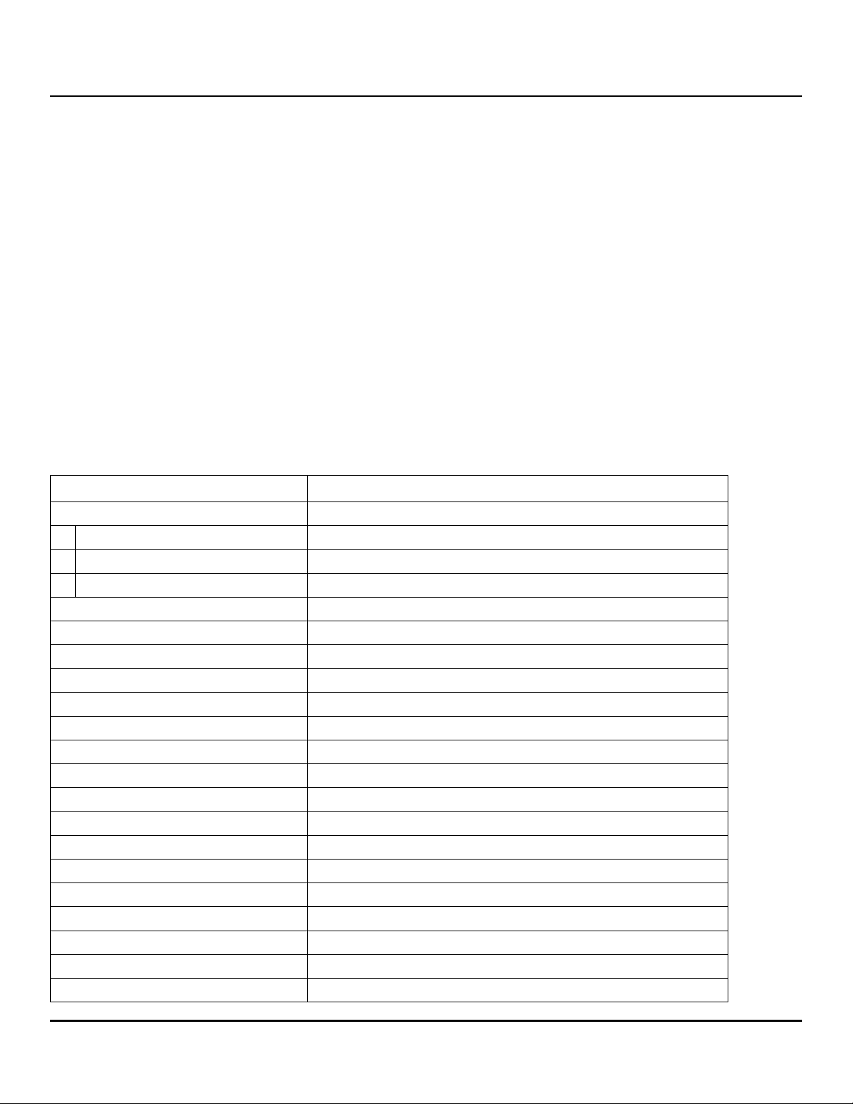
www.seagate.com Serial ATA (SATA) interface
Notes:
1. All pins are in a single row, with a 1.27mm (0.050”) pitch.
2. The comments on the mating sequence apply to the case of backplane blindmate connector only. In this case, the
mating sequences are:
— the ground pins P4 and P12.
— the pre-charge power pins and the other ground pins.
— the signal pins and the rest of the power pins.
3. There are three power pins for each voltage. One pin from each voltage is used for pre-charge when installed in a
blind-mate backplane configuration.
4. All used voltage pins (Vx) must be terminated.
5.3 Supported ATA commands
The following table lists Serial ATA standard commands that the drive supports. For a detailed description of the ATA
commands, refer to the Serial ATA: High Speed Serialized AT Attachment specification. See “S.M.A.R.T. commands”
on page 56 for details and subcommands used in the S.M.A.R.T. implementation.
Table 14 Supported ATA commands
Command name Command code (in hex)
Accessible Max Address Configuration
Get Native Max Address Ext 78H / 0000
Set Accessible Max Address Ext 78H / 0001
Freeze Accessible Max Address Ext 78H / 0002
Check Power Mode E5
Configure Stream 51
Download Microcode 92
Execute Device Diagnostics 90
Flush Cache E7
Flush Cache Extended EA
Get Physical Element Status 12
Identify Device EC
Idle E3
Idle Immediate E1
Read Buffer E4
Read DMA C8
Read DMA Extended 25
Read FPDMA Queued 60
Read Log DMA Ext 47
Read Log Ext 2F
Read Multiple C4
H
H
H
H
H
H
H
H
H
H
H
H
H
H
H
H
H
H
H
H
Seagate Exos X14 SATA Product Manual, Rev. C 33
www.seagate.com Serial ATA (SATA) interface
Command name Command code (in hex)
Read Multiple Extended 29
Read Sectors 20
Read Sectors Extended 24
Read Stream DMA Extended 2A
Read Verify Sectors 40
Read Verify Sectors Extended 42
Receive FPDMA Queued 65
Request Sense Data Ext 0B
Remove Element And Truncate 7C
H
H
H
H
H
H
H
H
H
Sanitize Device - Crypto Scramble B4H / 0011
Sanitize Device - Overwrite Ext B4H / 0014
Sanitize Device - Freeze Lock Ext B4H / 0020
Sanitize Device - Status Ext B4H / 0000
Security Disable Password F6
Security Erase Prepare F3
Security Erase Unit F4
Security Freeze F5
Security Set Password F1
Security Unlock F2
Seek 70
Send FPDMA Queued 64
Set Date & Time Ext 77
Set Features EF
Set Multiple Mode C6
Set Sector Configuration Ext B2
Sleep E6
H
H
H
H
H
H
H
H
H
H
H
H
H
S.M.A.R.T. Disable Operations B0H / D9
S.M.A.R.T. Enable/Disable Autosave B0H / D2
S.M.A.R.T. Enable Operations B0H / D8
S.M.A.R.T. Execute Offline B0H / D4
S.M.A.R.T. Read Attribute Thresholds B0H / D1
S.M.A.R.T. Read Data B0H / D0
S.M.A.R.T. Read Log Sector B0H / D5
S.M.A.R.T. Return Status B0H / DA
S.M.A.R.T. Save Attribute Values B0H / D3
S.M.A.R.T. Write Log Sector B0H / D6
(SED and ISE drives only)
H
H
H
H
H
H
H
H
H
H
H
H
H
H
Seagate Exos X14 SATA Product Manual, Rev. C 34
www.seagate.com Serial ATA (SATA) interface
Command name Command code (in hex)
Standby E2
Standby Immediate E0
H
H
Trusted Send 5EH (SED drives only)
Trusted Send DMA 5FH (SED drives only)
Trusted Receive 5CH (SED drives only)
Trusted Receive DMA 5DH (SED drives only)
Write Buffer E8
Write DMA CA
Write DMA Extended 35
Write DMA FUA Extended 3D
Write FPDMA Queued 61
Write Log DMA Ext 57
Write Log Extended 3F
Write Multiple C5
Write Multiple Extended 39
Write Multiple FUA Extended CE
Write Sectors 30
Write Sectors Extended 34
Write Stream DMA Extended 3A
Write Uncorrectable Extended 45
H
H
H
H
H
H
H
H
H
H
H
H
H
H
Seagate Exos X14 SATA Product Manual, Rev. C 35
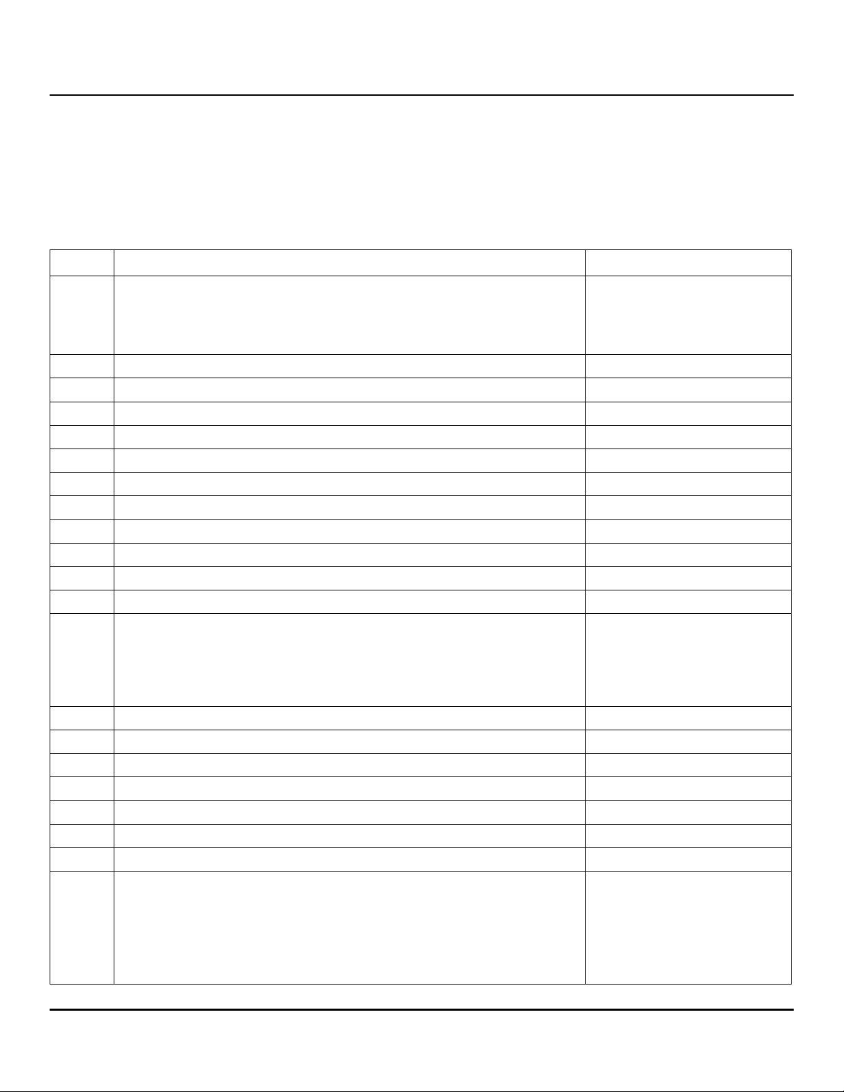
www.seagate.com Serial ATA (SATA) interface
5.3.1 Identify Device command
The Identify Device command (command code ECH) transfers information about the drive to the host following power
up. The data is organized as a single 512-byte block of data, whose contents are shown in Table 1 4 on page 33. All
reserved bits or words should be set to zero. Parameters listed with an “x” are drive-specific or vary with the state of
the drive. see Section 2.0 on page 7for default parameter settings.
The following commands contain drive-specific features that may not be included in the Serial ATA specification..
Table 15 Identify Device command
Word Description Value
0 Configuration information:
• Bit 15: 0 = ATA; 1 = ATAPI
0C5A
H
• Bit 7: removable media
• Bit 6: removable controller
• Bit 0: reserved
1 Obsolete 16,383
2 ATA-reserved C837
H
3 Obsolete 16
4 Retired 0000
5 Retired 0000
6 Obsolete 003F
7–9 Retired 0000
H
H
H
H
10–19 Serial number: (20 ASCII characters, 0000H = none) ASCII
20-21 Retired 0000
22 Obsolete 0000
H
H
23–26 Firmware revision (8 ASCII character string, padded with blanks to end of string) x.xx
27–46 Drive model number: (40 ASCII characters, padded with blanks to end of string) ST14000NM0018
ST14000NM0258
ST12000NM0008
ST12000NM0248
ST10000NM0478
ST10000NM0568
47 (Bits 7–0) Maximum sectors per interrupt on Read multiple and Write multiple (16) 8010
48 Trusted computing feature set supported bit 0 (SED only) 4000
49 Standard Standby timer, IORDY supported and may be disabled 2F00
50 Capabilities 4000
51-52 Obsolete xxxx
53-56 Words 54–58, 64–70 and 88 are valid xxxx
57–58 Obsolete xxxx
59 (Bit 15: 0) Block Erase Ext Not Supported - N
(512e) / 8002
H
H
H
H
H
H
H
(512E) / 5D02
5D10
H
H
H
(4KN)
(4KN)
(Bit 14: 1) Overwrite Ext Supported - Y
(Bit 13: X) Crypto Scramble Ext Supported (SED Only) - N
(Bit 12: 1) Sanitize feature set supported - Y
(Bit 11: 1) Commands allowed during sanitize op as specified in ACS-3 - Y
(Bit 10: 1) Sanitize Antifreeze Lock Ext command supported - Y
Seagate Exos X14 SATA Product Manual, Rev. C 36
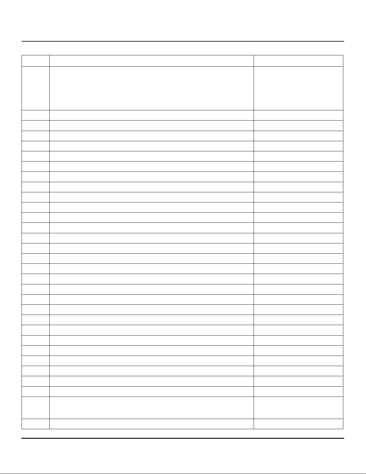
www.seagate.com Serial ATA (SATA) interface
Table 15 Identify Device command
Word Description Value
60–61 Total number of user-addressable LBA sectors available
0FFFFFFFh*
(see Section 2.2 for related information)
*Note: The maximum value allowed in this field is: 0FFFFFFFh (268,435,455 sectors,
137GB). Drives with capacities over 137GB will have 0FFFFFFFh in this field and the
actual number of user-addressable LBAs specified in words 100-103. This is required for
drives that support the 48-bit addressing feature.
62 Obsolete 0000
63 Multiword DMA active and modes supported (see note following this table) xx07
64 Advanced PIO modes supported (modes 3 and 4 supported) 0003
65 Minimum multiword DMA transfer cycle time per word (120 ns) 0078
66 Recommended multiword DMA transfer cycle time per word (120 ns) 0078
67 Minimum PIO cycle time without IORDY flow control (240 ns) 0078
68 Minimum PIO cycle time with IORDY flow control (120 ns) 0078
69 Additional supported 0008
70–74 ATA-reserved 0000
75 Queue depth 001F
76 Serial ATA capabilities 8D0E
77 (Bit 6:1) Send/Receive FPDMA Queued Commands Supported xx4x
78 Serial ATA features supported 80CC
79 Serial ATA features enabled xxxx
80 Major version number 0FE0
81 Minor version number 005E
82 Command sets supported 306B
83 Command sets supported 7561
84 Command sets support extension (see note following this table) 6173
85 Command sets enabled 3069
86 Command sets enabled B441
87 Command sets enable extension 6173
88 Ultra DMA support and current mode (see note following this table) xx7F
89 Security erase time xxxx
90 Enhanced security erase time xxxx
92 Master password revision code FFFE
93 Hardware reset value xxxx
95–99 ATA-reserved 0000
100–103 Total number of user-addressable LBA sectors available.
(see Section 2.2)
These words are required for drives that support the 48-bit addressing feature.
Maximum value: 0000FFFFFFFFFFFFh.
H
H
H
H
H
H
H
H
H
H
H
H
H
H
H
H
H
H
H
H
H
H
H
H
H
H
H
H
104–105 ATA-reserved 0000
H
Seagate Exos X14 SATA Product Manual, Rev. C 37
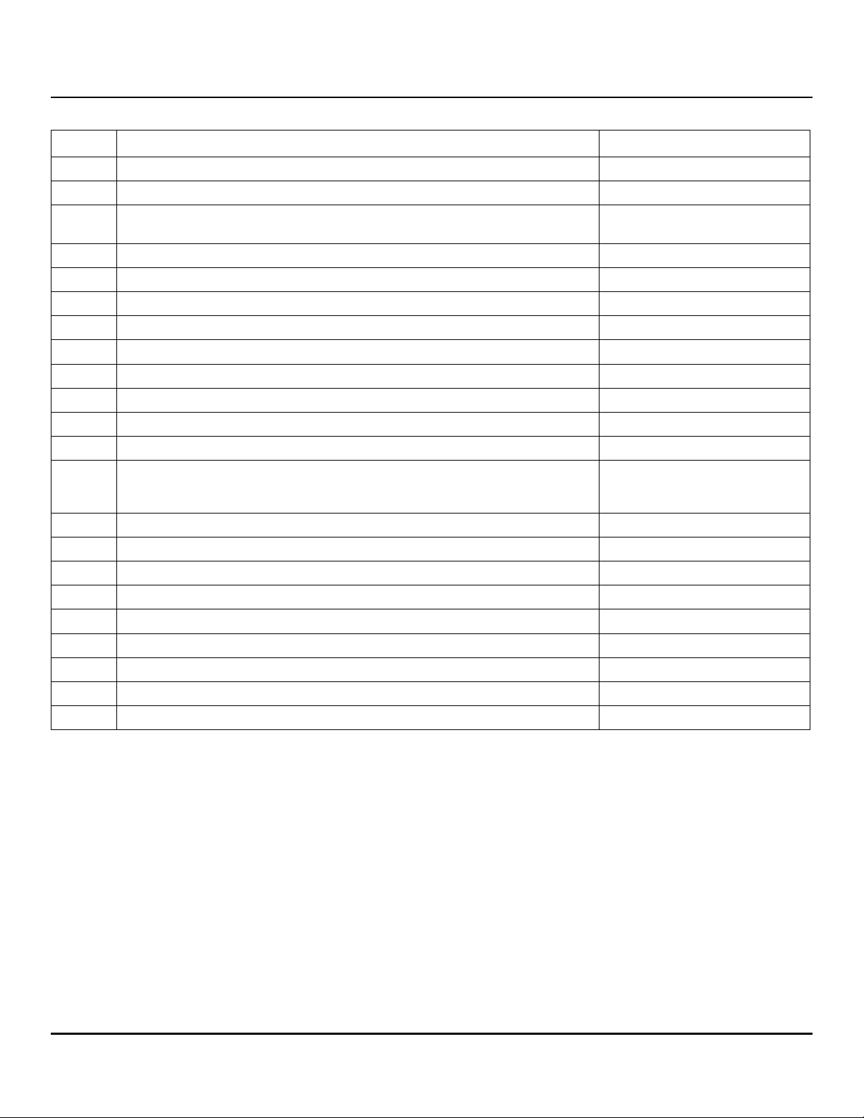
www.seagate.com Serial ATA (SATA) interface
Table 15 Identify Device command
Word Description Value
106 Physical/Logical sector size 6003H (512E) / 5000
107 ATA-reserved 0000
108–111 The mandatory value of the world wide name (WWN) for the drive.
H
Each drive will have a unique value.
NOTE: This field is valid if word 84, bit 8 is set to 1 indicating 64-bit WWN support.
112–118 ATA-reserved 0000
119 Commands and feature sets supported 43DE
120 Commands and feature sets supported or enabled 409C
121-127 ATA-reserved 0000
128 Security status 0021
129–159 Seagate-reserved xxxx
160–167 ATA-reserved 0000
H
H
H
H
H
H
H
168 Device Nominal Form Factor 3.5“
169–205 ATA-reserved 0000
206 SCT Command Transport command set.
If bit 0 is set to one, then the device supports SCT Command Transport.
xxBD
H
H
Bits 7:2 indicate individual SCT feature support.
207-216 ATA-reserved 0000
H
217 Nominal media rotation rate 7200
218-221 ATA-reserved 0000
222 Transport Major Version 11FF
223 Transport Minor Version 0000
224-229 ATA-reserved 0000
H
H
H
H
230-233 Extended Number of User Accessible Sectors (see Section 2.2)
H
(4KN)
234-254 ATA-reserved 0000
255 Integrity word xxA5
H
H
NOTE See the bit descriptions below for words 63, 84, and 88 of the Identify Drive data.
Seagate Exos X14 SATA Product Manual, Rev. C 38

www.seagate.com Serial ATA (SATA) interface
Description (if bit is set to 1)
Bit Word 63
0 Multiword DMA mode 0 is supported.
1 Multiword DMA mode 1 is supported.
2 Multiword DMA mode 2 is supported.
8 Multiword DMA mode 0 is currently active.
9 Multiword DMA mode 1 is currently active.
10 Multiword DMA mode 2 is currently active.
Bit Word 84
0 SMART error logging is supported.
1 SMART self-test is supported.
2 Media serial number is not supported.
3 Media Card Pass Through Command feature set is not supported.
4 Streaming feature set is not supported.
5 GPL feature set is supported.
6 WRITE DMA FUA EXT and WRITE MULTIPLE FUA EXT commands are supported.
7 WRITE DMA QUEUED FUA EXT command is not supported.
8 64-bit World Wide Name is supported.
9-10 Obsolete.
11-12 Reserved for TLC.
13 IDLE IMMEDIATE command with IUNLOAD feature is supported.
14 Shall be set to 1.
15 Shall be cleared to 0.
Bit Word 88
0 Ultra DMA mode 0 is supported.
1 Ultra DMA mode 1 is supported.
2 Ultra DMA mode 2 is supported.
3 Ultra DMA mode 3 is supported.
4 Ultra DMA mode 4 is supported.
5 Ultra DMA mode 5 is supported.
6 Ultra DMA mode 6 is supported.
8 Ultra DMA mode 0 is currently active.
9 Ultra DMA mode 1 is currently active.
10 Ultra DMA mode 2 is currently active.
11 Ultra DMA mode 3 is currently active.
12 Ultra DMA mode 4 is currently active.
13 Ultra DMA mode 5 is currently active.
14 Ultra DMA mode 6 is currently active.
Seagate Exos X14 SATA Product Manual, Rev. C 39
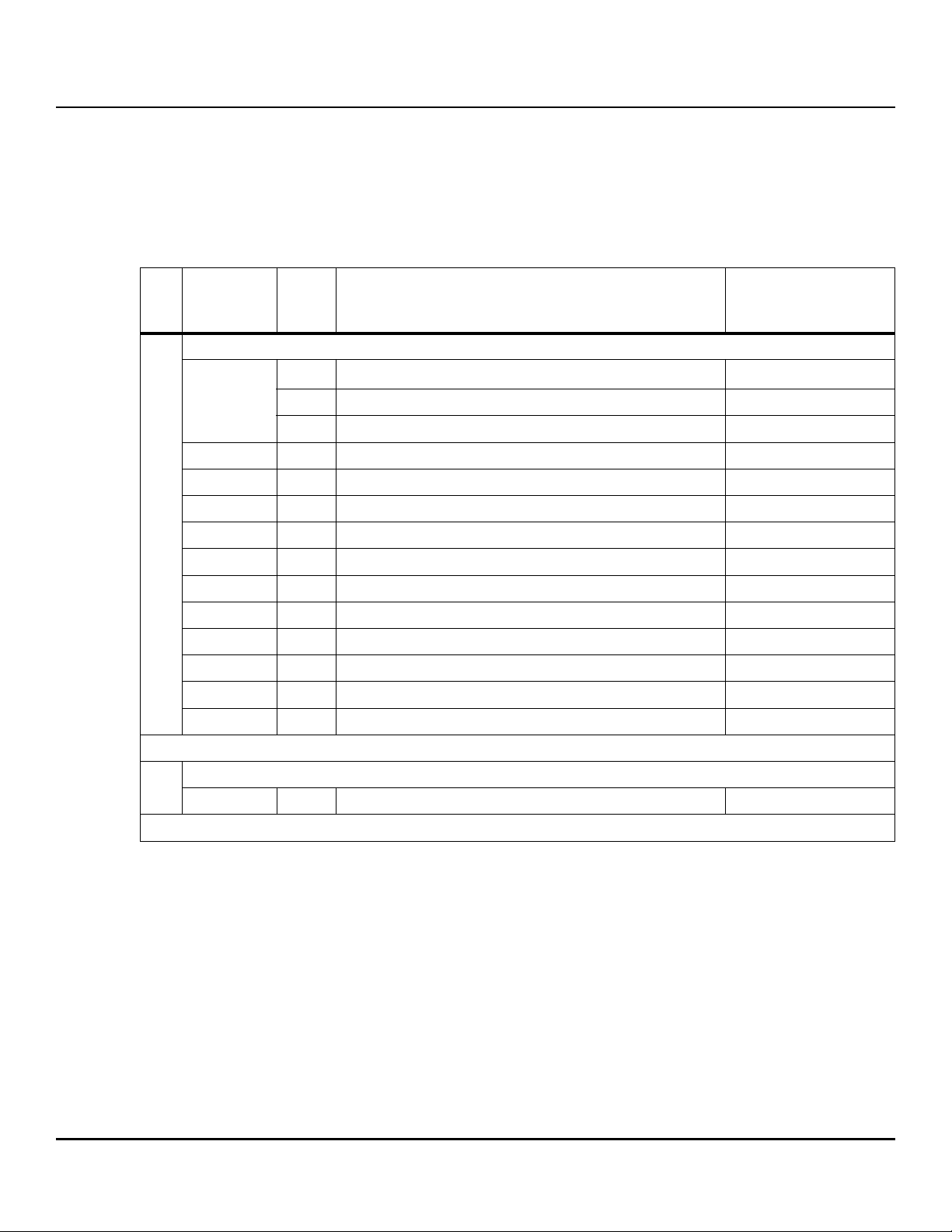
www.seagate.com Serial ATA (SATA) interface
5.3.2 Identify Device Data log
The IDENTIFY DEVICE Data log (log 30H) transfers information about the drive. The data is organized as a set of 512byte blocks of data, whose contents are shown in Table 2 on page 7. All reserved bits or words should be set to zero.
Parameters listed with an "x" are drive-specific or vary with the state of the drive.
The following may contain drive-specific features that may are included in the Serial ATA specification
Table 16 Identify Device Data log
Page
QWord Offset
(hex)
(dec)
List of supported pages
Bits Description
63:24 Reserved
Val ue
(hex)
0..7
8 Number of entries in the following list 09
9 Page number of the 1st supported ID data log page 00
10 Page number of the 2nd supported ID data log page 01
00
11 Page number of the next supported ID data log page 02
12 Page number of the next supported ID data log page 03
13 Page number of the next supported ID data log page 04
14 Page number of the next supported ID data log page 05
15 Page number of the next supported ID data log page 06
16 Page number of the next supported ID data log page 08
17 Page number of the last supported ID data log page 00
18..511 Reserved
Copy of IDENTIFY DEVICE data
01
0..511 Copy of IDENTIFY DEVICE command data
23:16 Page number 00
15:0 Revision number 0001
Seagate Exos X14 SATA Product Manual, Rev. C 40

www.seagate.com Serial ATA (SATA) interface
Table 16 Identify Device Data log (continued)
Capacity
Capacity page information header (QWord)
63 Shall be set to 1 1
02
0..7
8..15
16..23
24..31
62:24 Reserved
23:16 Page number 02
15:0 Revision number 0001
Device Capacity (QWord)
63 Shall be set to 1 1
62:48 Reserved 0
47:0 accessible capacity (see Section 2.2)
Physical/Logical Sector Size (QWord)
63 Contents of the QWord are valid 1
62 logical to physical sector relationship supported 1 (512E) / 0 (4KN)
61 logical sector size supported bit 1 (4KN) / 0 (512E)
60:22 Reserved 0
19:16 logical to physical sector relationship 0 (4KN) / 3 (512E)
15:0 logical sector offset 4000
H
Logical Sector Size (QWord)
63 Contents of the QWord are valid 1
62:32 Reserved 0
31:0 Logical Sector Size 4096b (4KN)
Nominal Buffer Size (QWord)
32..39
63 Contents of the QWord are valid 1
62:0 buffer size 256
40..511 Reserved 0
03 Supported Capabilities
Supported Capabilities page information header (QWord)
63 Shall be set to 1 1
0..7
62:24 Reserved
23:16 Page number 03
8..15 Supported Capabilities (QWord)
63 Shall be set to 1 1
62:55 Reserved 0
54 advanced background operation supported 0
53 persistent sense data reporting 0
52 sff-8447 reporting 1
Seagate Exos X14 SATA Product Manual, Rev. C 41
www.seagate.com Serial ATA (SATA) interface
Table 16 Identify Device Data log (continued)
51 definitive ending pattern supported 1
50 data set management xl supported 0
49 set sector configuration supported 1
48 zero ext supported 0
47 successful ncq command sense data supported 0
46 dlc supported 0
45 request sense device default supported 1
44 dsn supported 1
43 low power standby supported 0
42 set epc power source supported 0
41 amax addr supported 1
40 Reserved for CFA 0
39 drat supported 0
38 lps misalignment reporting supported 0
37 Reserved 0
36 read buffer dma supported 0
35 write buffer dma supported 0
34 Reserved 0
33 download microcode dma supported 0
32 28-bit supported 0
31 rzat supported 0
30 Reserved 0
29 nop supported 0
28 read buffer supported 1
27 write buffer supported 1
26 Reserved 0
25 read look-ahead supported 1
24 volatile write cache supported 1
23 smart supported 1
22 flush cache ext supported 1
21 Reserved 0
20 48-bit supported 1
19 Reserved 1
18 spin-up supported 1
17 puis supported 1
16 apm supported 0
15 Reserved for CFA 0
Seagate Exos X14 SATA Product Manual, Rev. C 42
www.seagate.com Serial ATA (SATA) interface
Table 16 Identify Device Data log (continued)
14 download microcode supported 1
13 unload supported 1
12 write fua ext supported 1
11 gpl supported 1
10 streaming supported 1
9 Reserved 0
8 smart self-test supported 1
7 smart error logging supported 1
6 epc supported 1
5 sense data supported 1
4 free-fall supported 0
3 dm mode 3 supported 1
2 gpl dma supported 1
1 write uncorrectable supported 1
0 wrv supported 1
16..23
24..31
32..39
DOWNLOAD MICROCODE Capabilities (QWord)
63 Contents of the QWord are valid 1
62:36 Reserved 0
35 dm clears nonactivated deferred data 0
34 dm offsets deferred supported 1
33 dm immediate supported 1
32 dm offsets immediate supported 1
31:16 dm maximum transfer size 0000
15:0 dm minimum transfer size 0000
Nominal Media Rotation Rate (QWord)
63 Shall be set to one 1
62:16 Reserved 0
15:0 nominal media rotation rate 7200
Form Factor (QWord)
63 Contents of the QWord are valid 1
62:4 Reserved 0
3:0 nominal form factor 3.5”
H
H
Write-Read-Verify Sector Count Mode 3 (QWord)
63 Contents of the QWord are valid 1
40..47
62:32 Reserved 0
31:0 wrm mode 3 count 0
Seagate Exos X14 SATA Product Manual, Rev. C 43
www.seagate.com Serial ATA (SATA) interface
Table 16 Identify Device Data log (continued)
Write-Read-Verify Sector Count Mode 2 (QWord)
48..55
56..71
72..79
63 Contents of the QWord are valid 1
62:32 Reserved 0
31:0 wrm mode 2 count 0
World wide name (DQWord)
127 Shall be set to one 1
126:64 Reserved 0
63:0 world wide name unique
DATA SET MANAGEMENT (QWord)
63 Shall be set to one 1
62:32 Reserved 0
31:16 max pages per dsm command 0
15:8 logical block markups supported 0
7:1 Reserved 0
0 trim supported 0
Utilization Per Unit Time (DQWord)
127 Shall be set to one 1
126:120 Reserved 0
80..95
96..103
119:112 utilization type
111:104 utilization units TB
103:96 utilization interval Per Year
95:34 Reserved 0
63:32 utilization b
31:0 utilization a 550
Utilization Usage Rate Support (QWord)
63 Contents of the QWord are valid 0
62:24 Reserved 0
23 setting rate basis supported 0
22:9 Reserved 0
8 since power on rate basis supported 0
7:5 Reserved 0
4 power on hours rate basis supported 0
3:1 Reserved 0
0 date/time rate basis supported 0
Combined
Writes and Reads
Seagate Exos X14 SATA Product Manual, Rev. C 44

www.seagate.com Serial ATA (SATA) interface
Table 16 Identify Device Data log (continued)
Zoned Capabilities (QWord)
104..111
112..119
120..127
63 Contents of the QWord are valid 0
62:2 Reserved 0
1:0 zoned 0
Supported ZAC Capabilities (QWord)
63 Contents of the QWord are valid 0
62:5 Reserved 0
4 non-data reset write pointers ext supported 0
3 non-data finish zone ext supported 0
2 non-data close zone ext supported 0
1 non-data open zone ext supported 0
0 report zones ext supported 0
Advanced Background Operations Capabilities (QWord)
63 Contents of the QWord are valid 0
62 abo foreground mode supported 0
61 abo ir mode supported 0
60:48 Reserved 0
47:16 abo minimum fraction 0
128..135
136..143
15:0 abo minimum supported timelimit 0
Advanced Background Operations Recommendations (QWord)
63 Contents of the QWord are valid 0
62:32 Reserved 0
31:16 device maintenance polling time 0
15:0 abo recommended abo start interval 0
Queue Depth (QWord)
63 Contents of the QWord are valid 0
62:5 Reserved 0
4:0 queue depth 0
Seagate Exos X14 SATA Product Manual, Rev. C 45

www.seagate.com Serial ATA (SATA) interface
Table 16 Identify Device Data log (continued)
Supported SCT Capabilities (QWord)
63 Contents of the QWord are valid 0
62:27 Reserved 0
26 sct write same function 103 supported 0
25 sct write same function 102 supported 0
24 sct write same function 101 supported 0
23:19 Reserved 0
18 sct write same function 3 supported 0
144..151
17 sct write same function 2 supported 0
16 sct write same function 1 supported 0
15:6 Reserved 0
5 sct data tables supported 0
4 sct feature control supported 0
3 sct error recovery control supported 0
2 sct write same supported 0
1 Reserved 0
0 sct supported 0
Depopulation Capabilities (QWord)
63 Contents of the QWord are valid 1
152..159
62:2 Reserved 0
1 get physical element status supported 1
0 remove element and truncate supported 1
35 Depopulation Execution Time (QWord) 1
160..167
168..503 Reserved
Bit Description:
63 Contents of the QWord are valid
1
62:0 DEPOPULATION TIME field (see 9.10.5.19) E861
H
Vendor Specific Supported Capabilities (QWord)
504..511
63 Contents of the QWord are valid 0
62:0 Vendor specific
04 Current Settings
Current Settings page information header (QWord)
63 Shall be set to 1 1
0..7
62:24 Reserved 0
23:16 Page number 04
Seagate Exos X14 SATA Product Manual, Rev. C 46
www.seagate.com Serial ATA (SATA) interface
Table 16 Identify Device Data log (continued)
Current Settings (QWord)
63 Shall be set to one 1
62:19 Reserved 0
18 successful ncq command sense data enabled 0
17 dlc enabled 0
16 dsn enabled 0
15 epc enabled 1
14 Reserved 0
13 volatile write cache enabled 1
12 Reserved 0
8..15
16..23
11 reverting to defaults enabled 0
10 sense data enabled 0
9 Reserved 0
8 non-volatile write cache 0
7read look-ahead 1
6smart enabled 1
5 Reserved 0
4 Reserved 0
3 puis enabled 0
2apm enabled 0
1 free-fall enabled 0
0wrv enabled 0
Feature Settings (QWord)
63 Contents of the QWord are valid 1
62:18 Reserved 0
17:16 power source 0
15:8 apm level 0
7:0 wrv mode 0
DMA Host Interface Sector Times (QWord)
24..31
32..39
Seagate Exos X14 SATA Product Manual, Rev. C 47
63 Contents of the QWord are valid 1
62:16 Reserved 0
15:0 dma sector time 0
PIO Host Interface Sector Times (QWord)
63 Contents of the QWord are valid 1
62:16 Reserved 0
15:0 pio sector time 0
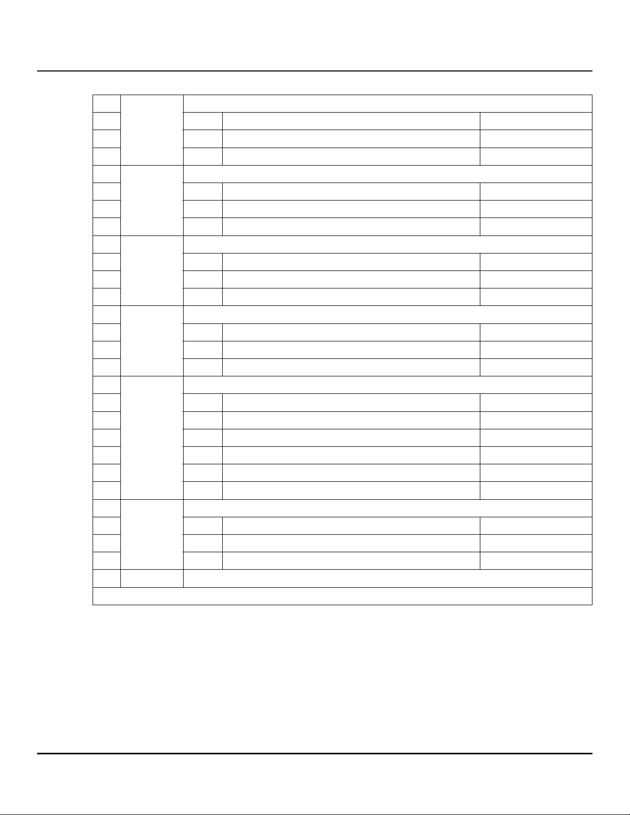
www.seagate.com Serial ATA (SATA) interface
Table 16 Identify Device Data log (continued)
Streaming Minimum Request Size (QWord)
40..47
48..55
56..63
64..71
63 Contents of the QWord are valid 1
62:16 Reserved 0
15:0 stream min request size 1000
Streaming Access Latency (QWord)
63 Contents of the QWord are valid 1
62:16 Reserved 0
15:0 stream access latency 0
Streaming Performance Granularity (QWord)
63 Contents of the QWord are valid 1
62:16 Reserved 0
15:0 stream granularity 2710
Free-fall Control Sensitivity (QWord)
63 Contents of the QWord are valid 1
62:16 Reserved 0
15:0 free-fall sensitivity 0
Device Maintenance Schedule (QWord)
63 Contents of the QWord are valid 0
H
H
62:58 Reserved 0
72..79
57:48 minimum inactive time in milliseconds 0
47:32 time scheduled for device maintenance 0
31:16 time to performance degradation 0
15:0 minimum inactive time 0
Advanced Background Operations Settings (QWord)
63 Contents of the QWord are valid 0
80..87
62:8 Reserved 0
7:0 abo_status 0
88..511 Reserved
Seagate Exos X14 SATA Product Manual, Rev. C 48
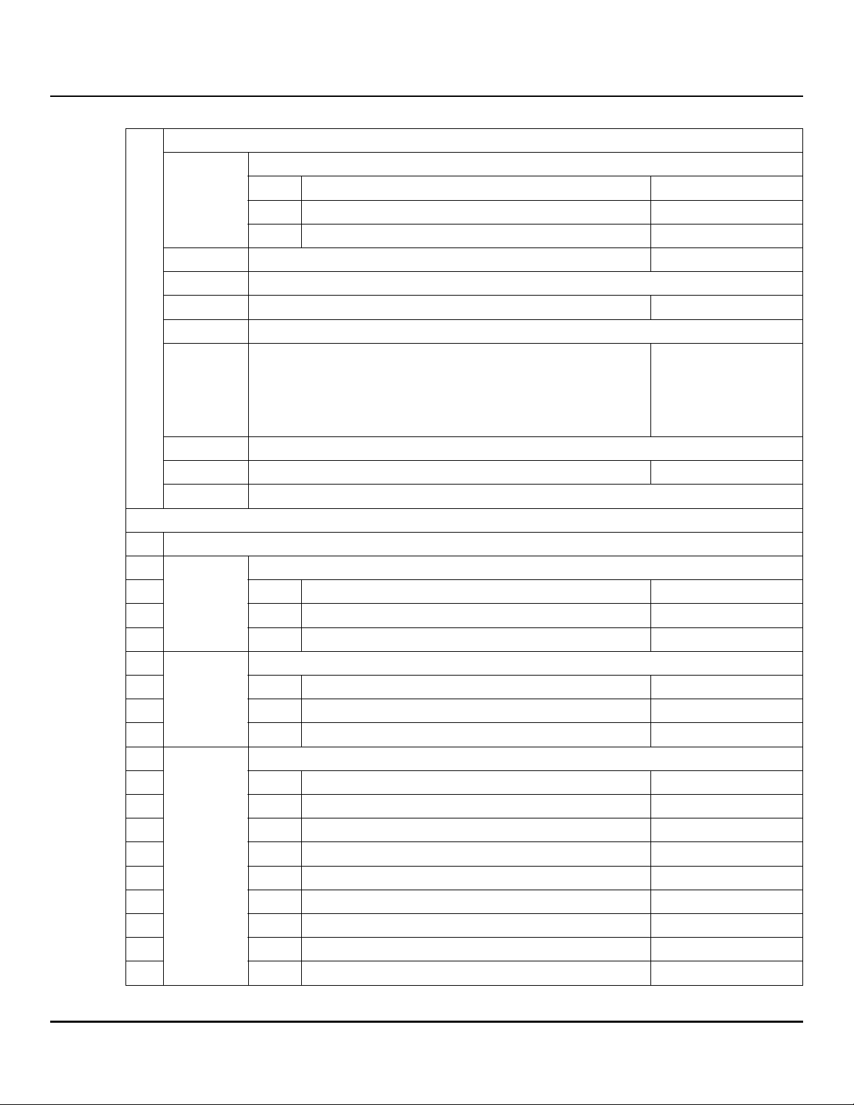
www.seagate.com Serial ATA (SATA) interface
Table 16 Identify Device Data log (continued)
Strings
Supported Capabilities page information header (QWord)
0..7
63 Shall be set to 1 1
62:24 Reserved
23:16 Page number 05
8..27 SERIAL NUMBER (ATA String) XXXXXXXX
28..31 Reserved
32..39 FIRMWARE REVISION (ATA String) XXXX
05
40..47 Reserved
48..87 MODEL NUMBER (ATA String)
88..95 Reserved
96..103
ADDITIONAL PRODUCT IDENTIFIER (ATA String) 0
104..511 Reserved
06 Security
Security page information header (QWord)
63 Shall be set to 1 1
0..7
62:24 Reserved
H
H
ST14000NM0018
ST14000NM0258
ST12000NM0008
ST12000NM0248
ST10000NM0478
ST10000NM0568
23:16 Page number 06
Master Password Identifier (QWord)
63 Contents of the QWord are valid 1
8..15
62:16 Reserved 0
15:0 master password identifier FFFE
H
Security Status (QWord)
63 Contents of the QWord are valid 1
62:7 Reserved 0
6 security supported 1
5 master password capability 0
16..23
4 enhanced security erase supported 1
3 security count expired 0
2 security frozen 0
1 security locked 0
0 security enabled 0
Seagate Exos X14 SATA Product Manual, Rev. C 49
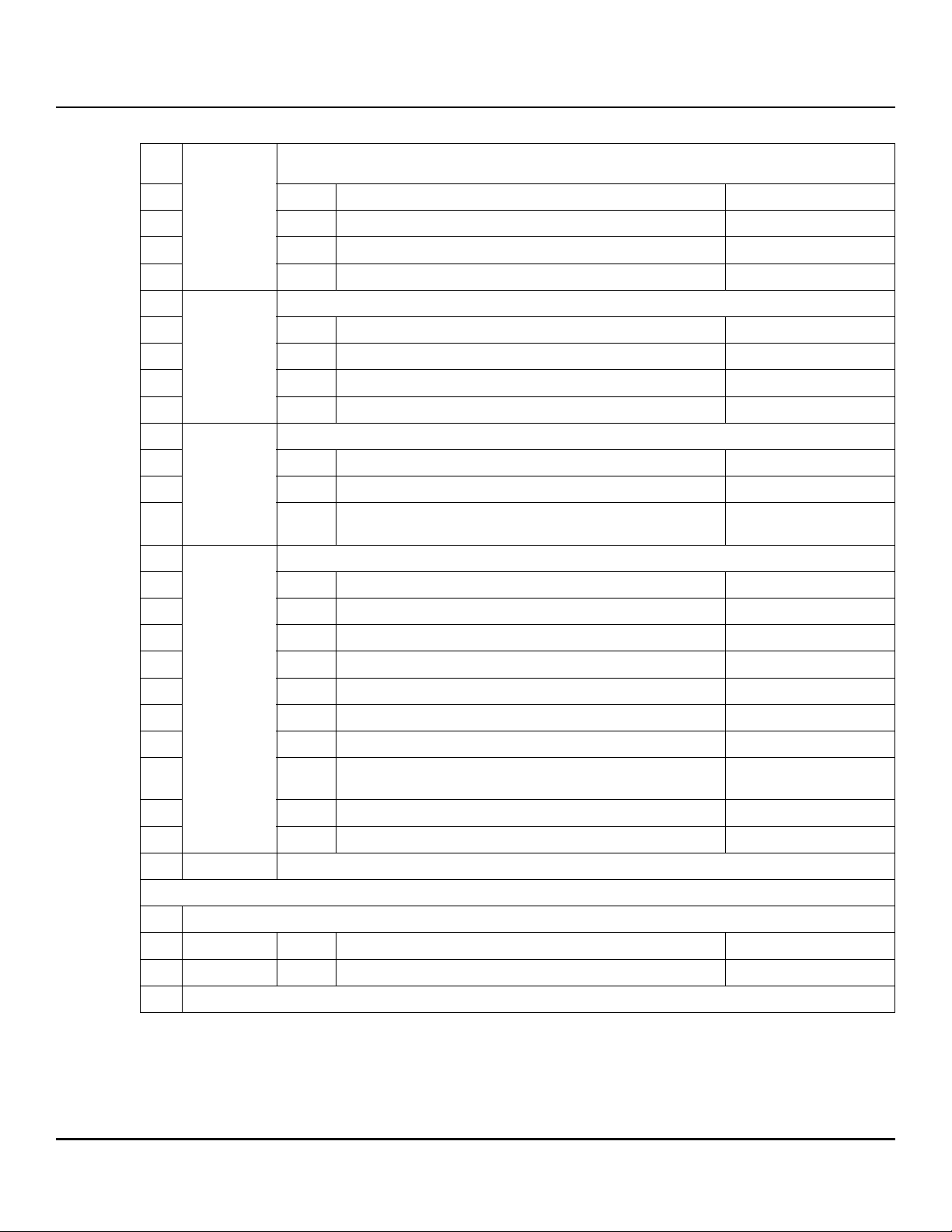
www.seagate.com Serial ATA (SATA) interface
Table 16 Identify Device Data log (continued)
Time required for an Enhanced Erase mode SECURITY ERASE UNIT command (QWord)
63 Contents of the QWord are valid 1
24..31
62:16 Reserved 0
15 enhanced security erase time format 1
32..39
40..47
48..55
14:0 enhanced security erase time 244
Time required for an Normal Erase mode SECURITY ERASE UNIT command (QWord)
63 Contents of the QWord are valid 1
62:16 Reserved 0
15 normal security erase time format 1
14:0 normal security erase time 244
Trusted Computing Feature Set (QWord)
63 Contents of the QWord are valid 1
62:1 Reserved 0
0 trusted computing supported
0
(1, SED drives only)
Security Capabilities (QWord)
63 Contents of the QWord are valid 1
62:8 Reserved 0
7 restricted sanitize overrides security 0
6 acs-3 commands allowed by sanitize 1
5 sanitize antifreeze lock supported 1
4 block erase supported 0
H
H
3 overwrite supported 1
2 crypto scramble supported
0
(1, SED and ISE drives only)
1 sanitize supported 1
0 encrypt all supported 0
56..511 Reserved
07 Parallel ATA
000..511 (Not supported for SATA drives) all zeros
08 Serial ATA
Seagate Exos X14 SATA Product Manual, Rev. C 50
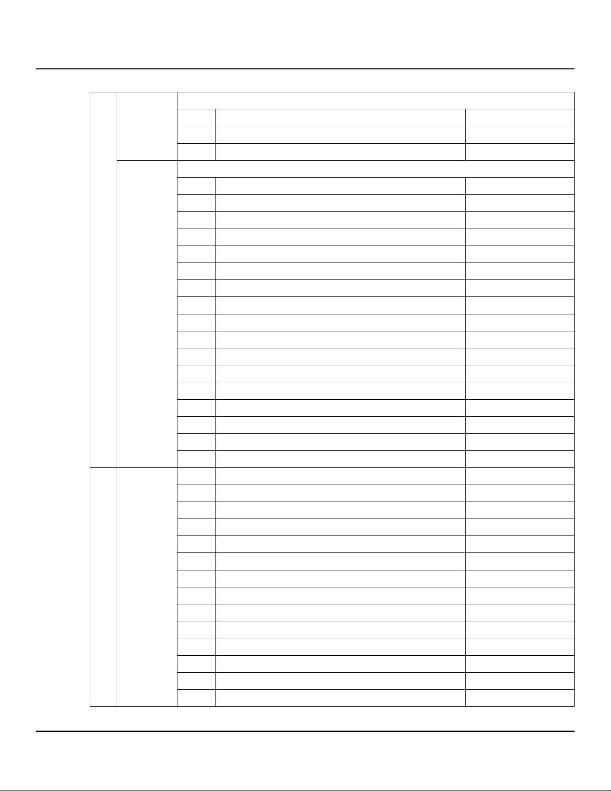
www.seagate.com Serial ATA (SATA) interface
Table 16 Identify Device Data log (continued)
Serial ATA page information header (QWord)
0..7
8..15
63 Shall be set to 1 1
62:24 Reserved
23:16 Page number 08
SATA Capabilities
63 Shall be set to one 1
62:32 Reserved 0
31 power disable feature always enabled 0
30 power disable feature supported 0
29 rebuild assist supported 0
28 dipm ssp preservation supported 0
27 hybrid information supported 0
26 devsleep to reducedpwrstate capability supported 0
25 device sleep supported 0
24 ncq autosense supported 1
23 software settings preservation supported 1
22 hardware feature control supported 0
21 in-order data delivery supported 0
20 device initiated power management supported 1
19 dma setup auto-activation supported 1
18 nonzero buffer offsets supported 0
17 send and receive queued commands supported 1
16 ncq non-data command supported 0
15 ncq streaming supported 0
14 read log dma ext as equivalent to read log ext supported 1
13 device automatic partial to slumber transitions supported 0
12 host automatic partial to slumber transitions supported 0
11 ncq priority information supported 0
10 unload while ncq commands are outstanding supported 1
9 sata phy event counters log supported 1
8 receipt of host initiated power management requests supported 0
7 ncq feature set supported 1
6:3 Reserved 0
2 sata gen3 signaling speed supported 1
1 sata gen2 signaling speed supported 1
0 sata gen1 signaling speed supported 1
Seagate Exos X14 SATA Product Manual, Rev. C 51
www.seagate.com Serial ATA (SATA) interface
Table 16 Identify Device Data log (continued)
Current SATA Settings (QWord)
63 Shall be set to one 1
62:14 Reserved 0
13 hybrid enabled 0
12 rebuild assist enabled 0
11 power disable feature enabled 0
10 device sleep enabled 0
16..23
24..39 Reserved
40..41 CURRENT HARDWARE FEATURE CONTROL IDENTIFIER (Word)
42..43 SUPPORTED HARDWARE FEATURE CONTROL IDENTIFIER (Word)
44..47 Reserved
48..55
9 automatic partial to slumber transitions enabled 0
8 software settings preservation enabled 1
7 hardware feature control is enabled 0
6 in-order data delivery enabled 0
5 device initiated power management enabled 0
4 dma setup auto-activation enabled 1
3 nonzero buffer offsets enabled 0
2:0 current negotiated serial ata signal speed (6.0, 3.0, 1.5) Gb/s
Device Sleep Timing Variables (QWord)
63 devslp timing variables supported 0
62:16 Reserved 0
15:8 devsleep exit timeout (deto) 0
7:5 Reserved 0
4:0 minimum devslp assertion time (mdat) 0
56..511 Reserved
Seagate Exos X14 SATA Product Manual, Rev. C 52
www.seagate.com Serial ATA (SATA) interface
5.3.3 Device Statistics log
The Device Statistics log (log 04H) transfers information about the drive. The data is organized as a set of 512-byte
blocks of data, whose contents are shown in Table 2 on page 7. All reserved bits or words should be set to zero.
Parameters listed with an "x" are drive-specific or vary with the state of the drive.
The following may contain drive-specific features that are included in the SATA specifications.
Table 17 Device Statistics log
Page
(hex)
00 List of supported log pages Yes
01 General Statistics
Lifetime Power-on Resets Yes
Power-on Hours Yes
Logical Sectors Written Yes
Number of Write Commands Yes
Logical Sectors Read Yes
Number of Read Commands Yes
Pending Error Count x
Workload Utilization No
Utilization Usage Rate No
Resource Availability x
Random Write Resources Used x
02 Free Fall Statistics
Number of Free-Fall Events Detected No
Overlimit Shock Events No
03 Rotating Media Statistics
Spindle Motor Power-on Hours Yes
Head Flying Hours Yes
Head Loaded Events Yes
Number of Reallocated Logical Sectors Yes
Read Recovery Attempts Yes
Number of Mechanical Start Failures Yes
Number of Reallocation Candidate Logical Sectors Yes
Number of High Priority Unload Events Yes
04 General Errors Statistics
Number of Reported Uncorrectable Errors Yes
Number of Resets Between Command Acceptance and Command Completion Yes
Statistic Supported
Physical Element Status Changed x
Seagate Exos X14 SATA Product Manual, Rev. C 53
www.seagate.com Serial ATA (SATA) interface
Table 17 Device Statistics log
05 Temperature Statistics
Current Temperature Yes
Average Short Term Temperature Yes
Average Long Term Temperature Yes
Highest Temperature Yes
Lowest Temperature Yes
Highest Average Short Term Temperature Yes
Lowest Average Short Term Temperature Yes
Highest Average Long Term Temperature Yes
Lowest Average Long Term Temperature Yes
Time in Over-Temperature Yes
Specified Maximum Operating Temperature Yes
Time in Under-Temperature Yes
Specified Minumum Operating Temperature Yes
06 Transport Statistics
Number of Hardware Resets Yes
Number of ASR Events Yes
Number of Interface CRC Errors Yes
07 Solid State Device Statistics
Percentage Used Endurance Indicator No
08 Zoned Device Statistics
Maximum Open Zones No
Maximum Explicitly Open Zones No
Maximum Implicitly Open Zones No
Minimum Empty Zones No
Maximum Non Sequential Zones No
Zones Emptied No
Suboptimal Write Commands No
Commands Exceeding Optimal Limit No
Failed Explicit Opens No
Read Rule Violations No
Write Rule Violations No
09..FE Reserved
FF Vendor Specific Statistics
TBD x
Seagate Exos X14 SATA Product Manual, Rev. C 54

www.seagate.com Serial ATA (SATA) interface
5.3.4 Set Features command
This command controls the implementation of various features that the drive supports. When the drive receives this
command, it sets BSY, checks the contents of the Features register, clears BSY and generates an interrupt. If the value
in the register does not represent a feature that the drive supports, the command is aborted. Power-on default has the
read look-ahead and write caching features enabled. The acceptable values for the Features register are defined as
follows:
Table 18 Set Features command values
02
03
Enable write cache (default).
H
Set transfer mode (based on value in Sector Count register).
H
Sector Count register values:
Set PIO mode to default (PIO mode 2).
00
H
01HSet PIO mode to default and disable IORDY (PIO mode 2).
08HPIO mode 0
09HPIO mode 1
0AHPIO mode 2
0BHPIO mode 3
0CHPIO mode 4 (default)
20HMultiword DMA mode 0
21HMultiword DMA mode 1
22HMultiword DMA mode 2
40HUltra DMA mode 0
41HUltra DMA mode 1
42HUltra DMA mode 2
43HUltra DMA mode 3
44HUltra DMA mode 4
45HUltra DMA mode 5
46HUltra DMA mode 6
10
55
82
90
AA
F1
Enable use of SATA features
H
Disable read look-ahead (read cache) feature.
H
Disable write cache
H
Disable use of SATA features
H
Enable read look-ahead (read cache) feature (default).
H
Report full capacity available
H
NOTE At power-on, or after a hardware or software reset, the default values of the
features are as indicated above.
Seagate Exos X14 SATA Product Manual, Rev. C 55
www.seagate.com Serial ATA (SATA) interface
5.3.5 S.M.A.R.T. commands
S.M.A.R.T. provides near-term failure prediction for disk drives. When S.M.A.R.T. is enabled, the drive monitors
predetermined drive attributes that are susceptible to degradation over time. If self-monitoring determines that a
failure is likely, S.M.A.R.T. makes a status report available to the host. Not all failures are predictable. S.M.A.R.T.
predictability is limited to the attributes the drive can monitor. For more information on S.M.A.R.T. commands and
implementation, see the Draft ATA-5 Standard.
SeaTools diagnostic software activates a built-in drive self-test (DST S.M.A.R.T. command for D4
unnecessary drive returns. The diagnostic software ships with all new drives and is also available at:
http://www.seagate.com/support/downloads/seatools/
.
This drive is shipped with S.M.A.R.T. features disabled. Users must have a recent BIOS or software package that
supports S.M.A.R.T. to enable this feature. The table below shows the S.M.A.R.T. command codes that the drive uses.
Table 19 S.M.A.R.T. commands
Code in features register S.M.A.R.T. command
D0
D2
D3
D4
D5
D6
D8
D9
DA
H
H
H
H
H
H
H
H
H
S.M.A.R.T. Read Data
S.M.A.R.T. Enable/Disable Attribute Autosave
S.M.A.R.T. Save Attribute Values
S.M.A.R.T. Execute Off-line Immediate (runs DST)
S.M.A.R.T. Read Log Sector
S.M.A.R.T. Write Log Sector
S.M.A.R.T. Enable Operations
S.M.A.R.T. Disable Operations
S.M.A.R.T. Return Status
NOTE If an appropriate code is not written to the Features Register, the command is
aborted and 0x
04 (abort) is written to the Error register.
) that eliminates
H
Seagate Exos X14 SATA Product Manual, Rev. C 56

Seagate Technology LLC
AMERICAS Seagate Technology LLC 10200 South De Anza Boulevard, Cupertino, California 95014, United States, 408-658-1000
ASIA/PACIFIC Seagate Singapore International Headquarters Pte. Ltd. 7000 Ang Mo Kio Avenue 5, Singapore 569877, 65-6485-3888
EUROPE, MIDDLE EAST AND AFRICA Seagate Technology SAS 16-18 rue du Dôme, 92100 Boulogne-Billancourt, France, 33 1-4186 10 00
Publication Number: 100835941, Rev. C
November 2018
 Loading...