


. . . . . . . . . . . . . . . . . . . . . . . . . . . . . . . . . . . . . . . . . . . . . . . . . . .
.
SCSI Interface
. . . . . . . . . . . . . . . . . . . . . . . . . . . . . . . . . . . . . . . . . . . . . . . . . . .
.
. . . . . . . . . . . . . . . . . . . . . . . . . . . . . . . . . . . . . . . . . . . . . . . . . . .
.
. . . . . . . . . . . . . . . . . . . . . . . . . . . . . . . . . . . . . . . . . . . . . . . . . . .
.
. . . . . . . . . . . . . . . . . . . . . . . . . . . . . . . . . . . . . . . . . . . . . . . . . . .
.
Product Manual, Volume 2
. . . . . . . . . . . . . . . . . . . . . . . . . . . . . . . . . . . . . . . . . . . . . . . . . . .
.


. . . . . . . . . . . . . . . . . . . . . . . . . . . . . . . . . . . . . . . . . . . . . .
SCSI Interface
. . . . . . . . . . . . . . . . . . . . . . . . . . . . . . . . . . . . . . . . . . . . . .
. . . . . . . . . . . . . . . . . . . . . . . . . . . . . . . . . . . . . . . . . . . . . .
. . . . . . . . . . . . . . . . . . . . . . . . . . . . . . . . . . . . . . . . . . . . . .
. . . . . . . . . . . . . . . . . . . . . . . . . . . . . . . . . . . . . . . . . . . . . .
Product Manual, Volume 2
. . . . . . . . . . . . . . . . . . . . . . . . . . . . . . . . . . . . . . . . . . . . . .

© 1997-1999 Seagate Technology, Inc. All rights reserved
Publication number: 77738479, Rev. J
April 1999
Seagate, Seagate Technology, and the Seagate logo are registered trademarks of Seagate
Technology, Inc. SeaFAX, SeaFONE, SeaBOARD, and SeaTDD are either trademarks or registered trademarks of Seagate Technology, Inc. or one of its subsidi arie s. All other trademarks
or registered trademarks are the property of their respective owners.
Seagate reserves the right to change, without notice, product of ferings or specifications. No
part of this publication may be reproduced i n any form without writt en per mission o f Seagate
Te c h n ology, Inc.

Revision status summary sheet
Revision Authority Date Signature Sheets Affected
A Issue 12/18/92 D . Ashby/
J. Averyt
1 thru 257.
B PLD:83345 8/18/93 1 thru 4, 4.1, 5 thru 193
deleted shs 194 thru 257.
(Technical changes on pages 5, 9, 10, 78,
93, 94, 104-107, 109, 136, 139-142, 144,
147, 149, 161-164, 166, 167, 181, 185
thru 193.)
C PLD:83534 93 Oct. 19 SS Revised sheets v thru ix, 1 thru 193.
(Technical changes on pages v, vii, 1, 4,
5, 7, 8, 47, 70, 73, 78, 79, 83, 84, 86, 87,
90, 91, 93, 94, 104, 105, 107, 112, 114,
119, 123-131, 136-144, 147-156, 158160, 162-170, 176, 178-180, 184, 185,
189, 192, and 193.)
D PLD:85300 5/26/94 SS v thru ix, 1 thru 189. (Technical changes
on pages 1, 8, 12, 26, 29, 34, 35, 70, 71,
77, 79, 80, 84, 85, 86, 95, 101, 104, 125,
150, 125, 150, 151, 160, 162, 163, and
164.)
E PLD:87127 01/24/95 QB v thru ix, 1 thru 187; deleted shs 188 and
189. Renumbered pages 94 thru 187.
(Technical changes on pages vi, vii, ix, 1,
2, 18, 21, 25, 26, 32, 33, 47, 50, 57, 68,
72, 74, 75, 77, 78, 79, 87, 88-90, 94, 105,
110, 114, 122, 124, 126, 127, 133, 135,
136, 139, 140, 143, 150, 152, 154, 158,
160, 162-164, 168-175, 178, 187.
F PLD: 86464 06/20/95 QB v thru ix, 1 thru 187. Added pages 188
thru 197.
G PLD:86785 05/02/96 QB v thru ix, 1 thru 197. Added pages 198-
213 and A-1.
H PLD:91095 08/18/97 QB Revised and retraced all sheets, added
214-216. (Technical changes on pages
85, 89, 97, 101, 126, 145, 152, 153, 157,
165, 168-170, 176, 177, 180, 181, 196,
198, 200-203.)
J v thru ix, 1 thru 216. Added pages 217 -
260.


SCSI Interface Product Manual, Rev. J v
Table of Contents
1.0 Interface requirements . . . . . . . . . . . . . . . . . . . . . . . . . . . . . . . . . . . . . . . . . . . . . . . . . . . . . . . . . . . . 1
1.1 How to use this interface manual. . . . . . . . . . . . . . . . . . . . . . . . . . . . . . . . . . . . . . . . . . . . . . . 1
1.1.1 Scope of SCSI-3 standards . . . . . . . . . . . . . . . . . . . . . . . . . . . . . . . . . . . . . . . . . . . 1
1.1.2 Applicable standards . . . . . . . . . . . . . . . . . . . . . . . . . . . . . . . . . . . . . . . . . . . . . . . . 2
1.2 General interface description . . . . . . . . . . . . . . . . . . . . . . . . . . . . . . . . . . . . . . . . . . . . . . . . . . 2
1.2.1 Glossary . . . . . . . . . . . . . . . . . . . . . . . . . . . . . . . . . . . . . . . . . . . . . . . . . . . . . . . . . . 3
1.2.2 Keywords . . . . . . . . . . . . . . . . . . . . . . . . . . . . . . . . . . . . . . . . . . . . . . . . . . . . . . . . . 8
1.3 Physical interface characteristics. . . . . . . . . . . . . . . . . . . . . . . . . . . . . . . . . . . . . . . . . . . . . . . 8
1.4 Summary of SCSI commands and messages . . . . . . . . . . . . . . . . . . . . . . . . . . . . . . . . . . . . . 9
2.0 SCSI bus. . . . . . . . . . . . . . . . . . . . . . . . . . . . . . . . . . . . . . . . . . . . . . . . . . . . . . . . . . . . . . . . . . . . . . . 11
2.1 SCSI bus signals . . . . . . . . . . . . . . . . . . . . . . . . . . . . . . . . . . . . . . . . . . . . . . . . . . . . . . . . . . 1 2
2.1.1 Drive select. . . . . . . . . . . . . . . . . . . . . . . . . . . . . . . . . . . . . . . . . . . . . . . . . . . . . . . 13
2.1.2 Signal values . . . . . . . . . . . . . . . . . . . . . . . . . . . . . . . . . . . . . . . . . . . . . . . . . . . . . 13
2.1.3 OR-tied signals . . . . . . . . . . . . . . . . . . . . . . . . . . . . . . . . . . . . . . . . . . . . . . . . . . . . 13
2.1.4 Signal sources . . . . . . . . . . . . . . . . . . . . . . . . . . . . . . . . . . . . . . . . . . . . . . . . . . . . 13
2.2 SCSI bus timing . . . . . . . . . . . . . . . . . . . . . . . . . . . . . . . . . . . . . . . . . . . . . . . . . . . . . . . . . . . 13
2.2.1 Arbitration delay (2.4 µs). . . . . . . . . . . . . . . . . . . . . . . . . . . . . . . . . . . . . . . . . . . . . 14
2.2.2 Assertion period (90 ns) . . . . . . . . . . . . . . . . . . . . . . . . . . . . . . . . . . . . . . . . . . . . . 14
2.2.3 Bus clear delay (800 ns). . . . . . . . . . . . . . . . . . . . . . . . . . . . . . . . . . . . . . . . . . . . . 14
2.2.4 Bus free delay (800 ns). . . . . . . . . . . . . . . . . . . . . . . . . . . . . . . . . . . . . . . . . . . . . . 14
2.2.5 Bus set delay (1.8 µs). . . . . . . . . . . . . . . . . . . . . . . . . . . . . . . . . . . . . . . . . . . . . . . 14
2.2.6 Bus settle delay (400 ns) . . . . . . . . . . . . . . . . . . . . . . . . . . . . . . . . . . . . . . . . . . . . 14
2.2.7 Cable skew delay (10 ns). . . . . . . . . . . . . . . . . . . . . . . . . . . . . . . . . . . . . . . . . . . . 14
2.2.8 Data release delay (400 ns) . . . . . . . . . . . . . . . . . . . . . . . . . . . . . . . . . . . . . . . . . . 14
2.2.9 Deskew delay (45 ns). . . . . . . . . . . . . . . . . . . . . . . . . . . . . . . . . . . . . . . . . . . . . . . 15
2.2.10 Disconnection delay (200 µs) . . . . . . . . . . . . . . . . . . . . . . . . . . . . . . . . . . . . . . . . . 15
2.2.11 Hold time (45 ns) . . . . . . . . . . . . . . . . . . . . . . . . . . . . . . . . . . . . . . . . . . . . . . . . . . 15
2.2.12 Negation period (90 ns) . . . . . . . . . . . . . . . . . . . . . . . . . . . . . . . . . . . . . . . . . . . . . 15
2.2.13 Reset hold time (25 µs). . . . . . . . . . . . . . . . . . . . . . . . . . . . . . . . . . . . . . . . . . . . . . 15
2.2.14 Selection abort time (200 µs) . . . . . . . . . . . . . . . . . . . . . . . . . . . . . . . . . . . . . . . . . 15
2.2.15 Selection timeout delay (250 ms recommended) . . . . . . . . . . . . . . . . . . . . . . . . . . 15
2.2.16 Transfer period (negotiated by Synchronous Data Transfer message) . . . . . . . . . 15
2.3 Fast synchronous transfer option. . . . . . . . . . . . . . . . . . . . . . . . . . . . . . . . . . . . . . . . . . . . . . 15
2.3.1 Fast assertion period (30 ns) . . . . . . . . . . . . . . . . . . . . . . . . . . . . . . . . . . . . . . . . . 15
2.3.2 Fast cable skew delay (5 ns) . . . . . . . . . . . . . . . . . . . . . . . . . . . . . . . . . . . . . . . . . 15
2.3.3 Fast deskew delay (20 ns) . . . . . . . . . . . . . . . . . . . . . . . . . . . . . . . . . . . . . . . . . . . 15
2.3.4 Fast hold time (10 ns) . . . . . . . . . . . . . . . . . . . . . . . . . . . . . . . . . . . . . . . . . . . . . . . 16
2.3.5 Fast negation period (30 ns). . . . . . . . . . . . . . . . . . . . . . . . . . . . . . . . . . . . . . . . . . 16
3.0 Logical characteristics. . . . . . . . . . . . . . . . . . . . . . . . . . . . . . . . . . . . . . . . . . . . . . . . . . . . . . . . . . . 17
3.1 SCSI bus phases . . . . . . . . . . . . . . . . . . . . . . . . . . . . . . . . . . . . . . . . . . . . . . . . . . . . . . . . . . 1 7
3.1.1 Bus Free phase . . . . . . . . . . . . . . . . . . . . . . . . . . . . . . . . . . . . . . . . . . . . . . . . . . . 17
3.1.2 Arbitration phase. . . . . . . . . . . . . . . . . . . . . . . . . . . . . . . . . . . . . . . . . . . . . . . . . . . 17
3.1.3 Selection phase . . . . . . . . . . . . . . . . . . . . . . . . . . . . . . . . . . . . . . . . . . . . . . . . . . . 18
3.1.3.1 Nonarbitrating system . . . . . . . . . . . . . . . . . . . . . . . . . . . . . . . . . . . . . 18
3.1.3.2 Arbitrating systems . . . . . . . . . . . . . . . . . . . . . . . . . . . . . . . . . . . . . . . 18
3.1.3.3 All systems . . . . . . . . . . . . . . . . . . . . . . . . . . . . . . . . . . . . . . . . . . . . . 18
3.1.3.4 Single initiator option . . . . . . . . . . . . . . . . . . . . . . . . . . . . . . . . . . . . . . 19
3.1.3.5 Selection time-out procedure . . . . . . . . . . . . . . . . . . . . . . . . . . . . . . . 19
3.1.3.6 Arbitration and selection under SCAM protocol . . . . . . . . . . . . . . . . . 19
3.1.4 Reselection phase . . . . . . . . . . . . . . . . . . . . . . . . . . . . . . . . . . . . . . . . . . . . . . . . . 19
3.1.4.1 Reselection procedure . . . . . . . . . . . . . . . . . . . . . . . . . . . . . . . . . . . . 20
3.1.4.2 Reselection timeout procedure . . . . . . . . . . . . . . . . . . . . . . . . . . . . . . 20
3.1.5 Information transfer phases . . . . . . . . . . . . . . . . . . . . . . . . . . . . . . . . . . . . . . . . . . 21
3.1.5.1 Asynchronous information transfer . . . . . . . . . . . . . . . . . . . . . . . . . . . 21

vi SCSI Interface Product Manual, Rev. J
3.1.5.2 Synchronous data transfer . . . . . . . . . . . . . . . . . . . . . . . . . . . . . . . . . .22
3.1.6 Command phase . . . . . . . . . . . . . . . . . . . . . . . . . . . . . . . . . . . . . . . . . . . . . . . . . . .22
3.1.7 Data phase. . . . . . . . . . . . . . . . . . . . . . . . . . . . . . . . . . . . . . . . . . . . . . . . . . . . . . . .22
3.1.7.1 Data in phase. . . . . . . . . . . . . . . . . . . . . . . . . . . . . . . . . . . . . . . . . . . .22
3.1.7.2 Data out phase. . . . . . . . . . . . . . . . . . . . . . . . . . . . . . . . . . . . . . . . . . .22
3.1.8 Status phase . . . . . . . . . . . . . . . . . . . . . . . . . . . . . . . . . . . . . . . . . . . . . . . . . . . . . .23
3.1.9 Message phase . . . . . . . . . . . . . . . . . . . . . . . . . . . . . . . . . . . . . . . . . . . . . . . . . . . .23
3.1.9.1 Message in phase . . . . . . . . . . . . . . . . . . . . . . . . . . . . . . . . . . . . . . . .23
3.1.9.2 Message out phase . . . . . . . . . . . . . . . . . . . . . . . . . . . . . . . . . . . . . . .23
3.1.10 Signal restrictions between phases . . . . . . . . . . . . . . . . . . . . . . . . . . . . . . . . . . . . .23
3.2 SCSI bus asynchronous conditions . . . . . . . . . . . . . . . . . . . . . . . . . . . . . . . . . . . . . . . . . . . . .23
3.2.1 Attention condition . . . . . . . . . . . . . . . . . . . . . . . . . . . . . . . . . . . . . . . . . . . . . . . . . .23
3.2.2 Reset condition . . . . . . . . . . . . . . . . . . . . . . . . . . . . . . . . . . . . . . . . . . . . . . . . . . . .24
3.3 SCSI bus phase sequences . . . . . . . . . . . . . . . . . . . . . . . . . . . . . . . . . . . . . . . . . . . . . . . . . .24
3.3.1 Nonarbitrating system . . . . . . . . . . . . . . . . . . . . . . . . . . . . . . . . . . . . . . . . . . . . . . .24
3.3.2 Arbitrating systems . . . . . . . . . . . . . . . . . . . . . . . . . . . . . . . . . . . . . . . . . . . . . . . . .25
3.3.3 All systems. . . . . . . . . . . . . . . . . . . . . . . . . . . . . . . . . . . . . . . . . . . . . . . . . . . . . . . .25
3.4 SCSI pointers . . . . . . . . . . . . . . . . . . . . . . . . . . . . . . . . . . . . . . . . . . . . . . . . . . . . . . . . . . . . .25
3.4.1 Current pointers. . . . . . . . . . . . . . . . . . . . . . . . . . . . . . . . . . . . . . . . . . . . . . . . . . . .26
3.4.2 Saved pointers. . . . . . . . . . . . . . . . . . . . . . . . . . . . . . . . . . . . . . . . . . . . . . . . . . . . .26
3.5 Message system specification. . . . . . . . . . . . . . . . . . . . . . . . . . . . . . . . . . . . . . . . . . . . . . . . .27
3.5.1 General message protocol. . . . . . . . . . . . . . . . . . . . . . . . . . . . . . . . . . . . . . . . . . . .27
3.5.2 Messages—General . . . . . . . . . . . . . . . . . . . . . . . . . . . . . . . . . . . . . . . . . . . . . . . .28
3.5.3 Message details. . . . . . . . . . . . . . . . . . . . . . . . . . . . . . . . . . . . . . . . . . . . . . . . . . . .29
3.5.3.1 One and two byte messages . . . . . . . . . . . . . . . . . . . . . . . . . . . . . . . .29
3.5.3.2 Extended Message (01h) . . . . . . . . . . . . . . . . . . . . . . . . . . . . . . . . . . .34
3.6 Message exception conditions handling . . . . . . . . . . . . . . . . . . . . . . . . . . . . . . . . . . . . . . . . .40
3.7 S.M.A.R.T. system . . . . . . . . . . . . . . . . . . . . . . . . . . . . . . . . . . . . . . . . . . . . . . . . . . . . . . . . .42
4.0 SCSI commands. . . . . . . . . . . . . . . . . . . . . . . . . . . . . . . . . . . . . . . . . . . . . . . . . . . . . . . . . . . . . . . . .43
4.1 Command implementation requirements . . . . . . . . . . . . . . . . . . . . . . . . . . . . . . . . . . . . . . . .43
4.1.1 Reserved . . . . . . . . . . . . . . . . . . . . . . . . . . . . . . . . . . . . . . . . . . . . . . . . . . . . . . . . .43
4.2 Command Descriptor Block (CDB) . . . . . . . . . . . . . . . . . . . . . . . . . . . . . . . . . . . . . . . . . . . . .43
4.2.1 Operation code . . . . . . . . . . . . . . . . . . . . . . . . . . . . . . . . . . . . . . . . . . . . . . . . . . . .44
4.2.2 Logical Unit Number (LUN) . . . . . . . . . . . . . . . . . . . . . . . . . . . . . . . . . . . . . . . . . . .45
4.2.3 Logical block address . . . . . . . . . . . . . . . . . . . . . . . . . . . . . . . . . . . . . . . . . . . . . . .45
4.2.4 Relative address bit . . . . . . . . . . . . . . . . . . . . . . . . . . . . . . . . . . . . . . . . . . . . . . . . .45
4.2.5 Transfer length. . . . . . . . . . . . . . . . . . . . . . . . . . . . . . . . . . . . . . . . . . . . . . . . . . . . .46
4.2.6 Control field . . . . . . . . . . . . . . . . . . . . . . . . . . . . . . . . . . . . . . . . . . . . . . . . . . . . . . .46
4.3 Status . . . . . . . . . . . . . . . . . . . . . . . . . . . . . . . . . . . . . . . . . . . . . . . . . . . . . . . . . . . . . . . . . . .47
4.4 Command examples . . . . . . . . . . . . . . . . . . . . . . . . . . . . . . . . . . . . . . . . . . . . . . . . . . . . . . . .49
4.4.1 Single command example . . . . . . . . . . . . . . . . . . . . . . . . . . . . . . . . . . . . . . . . . . . .49
4.4.2 Disconnect example. . . . . . . . . . . . . . . . . . . . . . . . . . . . . . . . . . . . . . . . . . . . . . . . .50
4.5 Timing examples. . . . . . . . . . . . . . . . . . . . . . . . . . . . . . . . . . . . . . . . . . . . . . . . . . . . . . . . . . .51
4.6 Command processing considerations and exception conditions. . . . . . . . . . . . . . . . . . . . . . .66
4.6.1 Auto Contingent Allegiance or Contingent Allegiance . . . . . . . . . . . . . . . . . . . . . . .66
4.6.1.1 Logical Unit response to Auto Contingent Allegiance or
Contingent Allegiance . . . . . . . . . . . . . . . . . . . . . . . . . . . . . . . . . . . . .66
4.6.1.2 Clearing an Auto Contingent Allegiance condition . . . . . . . . . . . . . . . .67
4.6.2 Overlapped commands . . . . . . . . . . . . . . . . . . . . . . . . . . . . . . . . . . . . . . . . . . . . . .67
4.6.3 Incorrect Logical Unit selection . . . . . . . . . . . . . . . . . . . . . . . . . . . . . . . . . . . . . . . .67
4.6.4 Sense data. . . . . . . . . . . . . . . . . . . . . . . . . . . . . . . . . . . . . . . . . . . . . . . . . . . . . . . .68
4.6.4.1 Asynchronous Event Reporting . . . . . . . . . . . . . . . . . . . . . . . . . . . . . .68
4.6.4.2 Autosense . . . . . . . . . . . . . . . . . . . . . . . . . . . . . . . . . . . . . . . . . . . . . .69
4.6.5 Unit attention condition . . . . . . . . . . . . . . . . . . . . . . . . . . . . . . . . . . . . . . . . . . . . . .69
4.6.6 Target Hard Reset. . . . . . . . . . . . . . . . . . . . . . . . . . . . . . . . . . . . . . . . . . . . . . . . . .70
4.6.7 Logical Unit Reset . . . . . . . . . . . . . . . . . . . . . . . . . . . . . . . . . . . . . . . . . . . . . . . . . .70
4.7 Queued tasks (formerly “Queued I/O Processes”) . . . . . . . . . . . . . . . . . . . . . . . . . . . . . . . . .71

SCSI Interface Product Manual, Rev. J vii
4.7.1 Untagged task queuing. . . . . . . . . . . . . . . . . . . . . . . . . . . . . . . . . . . . . . . . . . . . . . 71
4.7.2 Tagged task queuing . . . . . . . . . . . . . . . . . . . . . . . . . . . . . . . . . . . . . . . . . . . . . . . 71
4.8 Parameter rounding . . . . . . . . . . . . . . . . . . . . . . . . . . . . . . . . . . . . . . . . . . . . . . . . . . . . . . . . 72
4.9 Programmable operating definition . . . . . . . . . . . . . . . . . . . . . . . . . . . . . . . . . . . . . . . . . . . . 72
4.10 Incorrect initiator connection . . . . . . . . . . . . . . . . . . . . . . . . . . . . . . . . . . . . . . . . . . . . . . . . . 73
5.0 Command descriptions . . . . . . . . . . . . . . . . . . . . . . . . . . . . . . . . . . . . . . . . . . . . . . . . . . . . . . . . . . 75
5.1 Change Definition command (40h). . . . . . . . . . . . . . . . . . . . . . . . . . . . . . . . . . . . . . . . . . . . . 78
5.2 Compare command (39h) . . . . . . . . . . . . . . . . . . . . . . . . . . . . . . . . . . . . . . . . . . . . . . . . . . . 79
5.3 Copy command (18h). . . . . . . . . . . . . . . . . . . . . . . . . . . . . . . . . . . . . . . . . . . . . . . . . . . . . . . 79
5.4 Copy and Verify command (3Ah) . . . . . . . . . . . . . . . . . . . . . . . . . . . . . . . . . . . . . . . . . . . . . . 79
5.5 Format Unit command (04h) . . . . . . . . . . . . . . . . . . . . . . . . . . . . . . . . . . . . . . . . . . . . . . . . . 80
5.5.1 Format Unit parameter definition . . . . . . . . . . . . . . . . . . . . . . . . . . . . . . . . . . . . . . 81
5.5.2 Format Unit parameter list . . . . . . . . . . . . . . . . . . . . . . . . . . . . . . . . . . . . . . . . . . . 83
5.5.2.1 Defect List header. . . . . . . . . . . . . . . . . . . . . . . . . . . . . . . . . . . . . . . . 83
5.5.2 . 2 Initia l izatio n P a ttern Descripto r . . . . . . . . . . . . . . . . . . . . . . . . . . . . . . 8 4
5.5.2.3 Defect List formats . . . . . . . . . . . . . . . . . . . . . . . . . . . . . . . . . . . . . . . 85
5.6 Inquiry command (12h) . . . . . . . . . . . . . . . . . . . . . . . . . . . . . . . . . . . . . . . . . . . . . . . . . . . . . 87
5.6.1 Drive Standard Inquiry Data . . . . . . . . . . . . . . . . . . . . . . . . . . . . . . . . . . . . . . . . . . 88
5.6.2 Vital Product Data pages . . . . . . . . . . . . . . . . . . . . . . . . . . . . . . . . . . . . . . . . . . . . 91
5.6.3 Unit Serial Number page (80h). . . . . . . . . . . . . . . . . . . . . . . . . . . . . . . . . . . . . . . . 92
5.6.4 Implemented Operating Definition page (81h) . . . . . . . . . . . . . . . . . . . . . . . . . . . . 92
5.6.5 Device Identification page (83h) . . . . . . . . . . . . . . . . . . . . . . . . . . . . . . . . . . . . . . . 93
5.6.6 Firmware Numbers page (C0h) . . . . . . . . . . . . . . . . . . . . . . . . . . . . . . . . . . . . . . . 96
5.6.7 Date Code page (C1h) . . . . . . . . . . . . . . . . . . . . . . . . . . . . . . . . . . . . . . . . . . . . . . 98
5.6.8 Jumper Settings page (C2h). . . . . . . . . . . . . . . . . . . . . . . . . . . . . . . . . . . . . . . . . . 99
5.6.9 Device Behavior page (C3h). . . . . . . . . . . . . . . . . . . . . . . . . . . . . . . . . . . . . . . . . 101
5.7 Lock-unlock Cache command (36h). . . . . . . . . . . . . . . . . . . . . . . . . . . . . . . . . . . . . . . . . . . 101
5.8 Log Select command (4Ch) . . . . . . . . . . . . . . . . . . . . . . . . . . . . . . . . . . . . . . . . . . . . . . . . . 102
5.8.1 Write, Read, and Verify Error Counter pages (02h, 03h, and 05h). . . . . . . . . . . . 107
5.8.2 Non-Medium Error page (06h) . . . . . . . . . . . . . . . . . . . . . . . . . . . . . . . . . . . . . . . 108
5.8.3 Cache Statistics page (37h) . . . . . . . . . . . . . . . . . . . . . . . . . . . . . . . . . . . . . . . . . 108
5.8.4 Factory Log page (3Eh) . . . . . . . . . . . . . . . . . . . . . . . . . . . . . . . . . . . . . . . . . . . . 109
5.9 Log Sense command (4Dh) . . . . . . . . . . . . . . . . . . . . . . . . . . . . . . . . . . . . . . . . . . . . . . . . . 110
5.10 Mode Select (6) command (15h) . . . . . . . . . . . . . . . . . . . . . . . . . . . . . . . . . . . . . . . . . . . . . 112
5.10.1 Mode Select parameter list. . . . . . . . . . . . . . . . . . . . . . . . . . . . . . . . . . . . . . . . . . 112
5.10.2 Mode Select page descriptors . . . . . . . . . . . . . . . . . . . . . . . . . . . . . . . . . . . . . . . 114
5.11 Mode Select (10) command (55h) . . . . . . . . . . . . . . . . . . . . . . . . . . . . . . . . . . . . . . . . . . . . 116
5.11.1 Mode Select (10) parameter list . . . . . . . . . . . . . . . . . . . . . . . . . . . . . . . . . . . . . . 116
5.12 Mode Sense (6) command (1Ah) . . . . . . . . . . . . . . . . . . . . . . . . . . . . . . . . . . . . . . . . . . . . . 119
5.12.1 Mode Sense page descriptor header . . . . . . . . . . . . . . . . . . . . . . . . . . . . . . . . . . 122
5.12.2 Error Recovery page (01h). . . . . . . . . . . . . . . . . . . . . . . . . . . . . . . . . . . . . . . . . . 123
5.12.3 Disconnect/Reconnect Control page (02h). . . . . . . . . . . . . . . . . . . . . . . . . . . . . . 126
5.12.4 Format Parameters page (03h) . . . . . . . . . . . . . . . . . . . . . . . . . . . . . . . . . . . . . . 128
5.12.5 Rigid Drive Geometry Parameters page (04h) . . . . . . . . . . . . . . . . . . . . . . . . . . . 130
5.12.6 Verify Error Recovery page (07h). . . . . . . . . . . . . . . . . . . . . . . . . . . . . . . . . . . . . 132
5.12.7 Caching Parameters page (08h). . . . . . . . . . . . . . . . . . . . . . . . . . . . . . . . . . . . . . 134
5.12.8 Control Mode page (0Ah) . . . . . . . . . . . . . . . . . . . . . . . . . . . . . . . . . . . . . . . . . . . 137
5.12.9 Notch page (0Ch) . . . . . . . . . . . . . . . . . . . . . . . . . . . . . . . . . . . . . . . . . . . . . . . . . 139
5.12.10 Power Condition page (0Dh or 1Ah). . . . . . . . . . . . . . . . . . . . . . . . . . . . . . . . . . . 141
5.12.11 Xor Control Mode page (10h) . . . . . . . . . . . . . . . . . . . . . . . . . . . . . . . . . . . . . . . . 142
5.12.12 Unit Attention Parameters page (00h) . . . . . . . . . . . . . . . . . . . . . . . . . . . . . . . . . 144
5.12.13 Informational Exceptions Control page (1Ch). . . . . . . . . . . . . . . . . . . . . . . . . . . . 1 46
5.13 Mode Sense (10) command (5Ah). . . . . . . . . . . . . . . . . . . . . . . . . . . . . . . . . . . . . . . . . . . . 149
5.14 Move Medium command (A7h) . . . . . . . . . . . . . . . . . . . . . . . . . . . . . . . . . . . . . . . . . . . . . . 152
5.15 Persistent Reserve In command (5Eh) . . . . . . . . . . . . . . . . . . . . . . . . . . . . . . . . . . . . . . . . 153
5.15.1 Persistent Reserve In parameter data for Read Keys . . . . . . . . . . . . . . . . . . . . . 154
5.15.2 Persistent Reserve In parameter data for Read Reservations . . . . . . . . . . . . . . . 155

viii SCSI Interface Product Manual, Rev. J
5.16 Persistent Reserve Out command (5Fh) . . . . . . . . . . . . . . . . . . . . . . . . . . . . . . . . . . . . . . . .158
5.16.1 Persistent Reserve Out parameter list. . . . . . . . . . . . . . . . . . . . . . . . . . . . . . . . . .159
5.17 Prefetch command (34h). . . . . . . . . . . . . . . . . . . . . . . . . . . . . . . . . . . . . . . . . . . . . . . . . . . .161
5.18 Prevent/Allow Medium Removal command (1E h). . . . . . . . . . . . . . . . . . . . . . . . . . . . . . . . .161
5.19 Read command (08h) . . . . . . . . . . . . . . . . . . . . . . . . . . . . . . . . . . . . . . . . . . . . . . . . . . . . . .162
5.20 Read Buffer command (3Ch) . . . . . . . . . . . . . . . . . . . . . . . . . . . . . . . . . . . . . . . . . . . . . . . .164
5.20.1 Read Combined Descriptor Header and Data mode (0000b) . . . . . . . . . . . . . . . .165
5.20.2 Read Data mode (0010b) . . . . . . . . . . . . . . . . . . . . . . . . . . . . . . . . . . . . . . . . . . .165
5.20.3 Read Buffer Descriptor mode (0011b). . . . . . . . . . . . . . . . . . . . . . . . . . . . . . . . . .165
5.20.4 Read Data from Echo Buffer mode (1010b) . . . . . . . . . . . . . . . . . . . . . . . . . . . . .166
5.20.5 Echo Buffer Descriptor mode (1011b) . . . . . . . . . . . . . . . . . . . . . . . . . . . . . . . . . .166
5.21 Read Capacity command (25h). . . . . . . . . . . . . . . . . . . . . . . . . . . . . . . . . . . . . . . . . . . . . . .167
5.22 Read Defect Data (10) command (37h) . . . . . . . . . . . . . . . . . . . . . . . . . . . . . . . . . . . . . . . .169
5.23 Read Defect Data (12) command (B7h) . . . . . . . . . . . . . . . . . . . . . . . . . . . . . . . . . . . . . . . .171
5.24 Read Element Status command (B4h) . . . . . . . . . . . . . . . . . . . . . . . . . . . . . . . . . . . . . . . . .172
5.25 Read Extended command (28h) . . . . . . . . . . . . . . . . . . . . . . . . . . . . . . . . . . . . . . . . . . . . . .173
5.26 Read Long command (3Eh) . . . . . . . . . . . . . . . . . . . . . . . . . . . . . . . . . . . . . . . . . . . . . . . . .175
5.27 Reassign Blocks command (07h) . . . . . . . . . . . . . . . . . . . . . . . . . . . . . . . . . . . . . . . . . . . . .176
5.27.1 Reassign Blocks defect list . . . . . . . . . . . . . . . . . . . . . . . . . . . . . . . . . . . . . . . . . .177
5.28 Rebuild command (81h) . . . . . . . . . . . . . . . . . . . . . . . . . . . . . . . . . . . . . . . . . . . . . . . . . . . .178
5.28.1 Rebuild and Regenerate parameter data. . . . . . . . . . . . . . . . . . . . . . . . . . . . . . . .179
5.29 Receive Diagnostic Results command (1Ch) . . . . . . . . . . . . . . . . . . . . . . . . . . . . . . . . . . . .181
5.29.1 Supported Diagnostic Pages . . . . . . . . . . . . . . . . . . . . . . . . . . . . . . . . . . . . . . . . .183
5.29.2 Translate Address page (40h). . . . . . . . . . . . . . . . . . . . . . . . . . . . . . . . . . . . . . . .183
5.30 Regenerate command (82h) . . . . . . . . . . . . . . . . . . . . . . . . . . . . . . . . . . . . . . . . . . . . . . . . .185
5.31 Release (6) command (17h) . . . . . . . . . . . . . . . . . . . . . . . . . . . . . . . . . . . . . . . . . . . . . . . . .187
5.31.1 Logical Unit Release . . . . . . . . . . . . . . . . . . . . . . . . . . . . . . . . . . . . . . . . . . . . . . .187
5.31.2 Extent Release. . . . . . . . . . . . . . . . . . . . . . . . . . . . . . . . . . . . . . . . . . . . . . . . . . . .187
5.31.3 Third Party Release. . . . . . . . . . . . . . . . . . . . . . . . . . . . . . . . . . . . . . . . . . . . . . . .187
5.32 Release (10) command (57h) . . . . . . . . . . . . . . . . . . . . . . . . . . . . . . . . . . . . . . . . . . . . . . . .188
5.33 Report LUNs command (A0h). . . . . . . . . . . . . . . . . . . . . . . . . . . . . . . . . . . . . . . . . . . . . . . .189
5.34 Request Sense command (03h) . . . . . . . . . . . . . . . . . . . . . . . . . . . . . . . . . . . . . . . . . . . . . .191
5.34.1 Extended Sense Data Format . . . . . . . . . . . . . . . . . . . . . . . . . . . . . . . . . . . . . . . .192
5.34.2 Sense Keys . . . . . . . . . . . . . . . . . . . . . . . . . . . . . . . . . . . . . . . . . . . . . . . . . . . . . .195
5.34.3 Extended Sense, Additional Sense and Additional Sense Qualifier codes . . . . . .196
5.34.3.1 Deferred errors. . . . . . . . . . . . . . . . . . . . . . . . . . . . . . . . . . . . . . . . . .199
5.35 Reserve (6) command (16h) . . . . . . . . . . . . . . . . . . . . . . . . . . . . . . . . . . . . . . . . . . . . . . . . .200
5.35.1 Logical Unit Reservation . . . . . . . . . . . . . . . . . . . . . . . . . . . . . . . . . . . . . . . . . . . .200
5.35.2 Extent Reservation. . . . . . . . . . . . . . . . . . . . . . . . . . . . . . . . . . . . . . . . . . . . . . . . .200
5.35.3 Third Party Reservation. . . . . . . . . . . . . . . . . . . . . . . . . . . . . . . . . . . . . . . . . . . . .201
5.35.4 Superseding Reservations. . . . . . . . . . . . . . . . . . . . . . . . . . . . . . . . . . . . . . . . . . .201
5.35.5 Reservations . . . . . . . . . . . . . . . . . . . . . . . . . . . . . . . . . . . . . . . . . . . . . . . . . . . . .201
5.36 Reserve (10) command (56h) . . . . . . . . . . . . . . . . . . . . . . . . . . . . . . . . . . . . . . . . . . . . . . . .202
5.37 Rezero Unit command (01h) . . . . . . . . . . . . . . . . . . . . . . . . . . . . . . . . . . . . . . . . . . . . . . . . .203
5.38 Search Data Equal command (31h) . . . . . . . . . . . . . . . . . . . . . . . . . . . . . . . . . . . . . . . . . . .203
5.39 Search Data High command (30h) . . . . . . . . . . . . . . . . . . . . . . . . . . . . . . . . . . . . . . . . . . . .203
5.40 Search Data Low command (32h). . . . . . . . . . . . . . . . . . . . . . . . . . . . . . . . . . . . . . . . . . . . .203
5.41 Seek command (0Bh) . . . . . . . . . . . . . . . . . . . . . . . . . . . . . . . . . . . . . . . . . . . . . . . . . . . . . .204
5.42 Seek Extended command (2Bh) . . . . . . . . . . . . . . . . . . . . . . . . . . . . . . . . . . . . . . . . . . . . . .205
5.43 Send Diagnostic command (1Dh) . . . . . . . . . . . . . . . . . . . . . . . . . . . . . . . . . . . . . . . . . . . . .206
5.43.1 Supported Diagnostic page—Send Diagno stic . . . . . . . . . . . . . . . . . . . . . . . . . . .207
5.43.2 Translate Address page—Send Diagnostic. . . . . . . . . . . . . . . . . . . . . . . . . . . . . .207
5.44 Set Limits command (33h) . . . . . . . . . . . . . . . . . . . . . . . . . . . . . . . . . . . . . . . . . . . . . . . . . .208
5.45 Start/Stop Unit command (1Bh) . . . . . . . . . . . . . . . . . . . . . . . . . . . . . . . . . . . . . . . . . . . . . .209
5.46 Synchronize Cache comm and (35h) . . . . . . . . . . . . . . . . . . . . . . . . . . . . . . . . . . . . . . . . . . .210
5.47 Test Unit Ready command (00h) . . . . . . . . . . . . . . . . . . . . . . . . . . . . . . . . . . . . . . . . . . . . .211
5.48 Verify command (2Fh). . . . . . . . . . . . . . . . . . . . . . . . . . . . . . . . . . . . . . . . . . . . . . . . . . . . . .212
5.49 Write command (0Ah) . . . . . . . . . . . . . . . . . . . . . . . . . . . . . . . . . . . . . . . . . . . . . . . . . . . . . .213

SCSI Interface Product Manual, Rev. J ix
5.50 Write and Verify command (2Eh) . . . . . . . . . . . . . . . . . . . . . . . . . . . . . . . . . . . . . . . . . . . . . 214
5.51 Write Buffer command (3Bh) . . . . . . . . . . . . . . . . . . . . . . . . . . . . . . . . . . . . . . . . . . . . . . . . 215
5.51.1 Combined Header and Data mode (0000b) . . . . . . . . . . . . . . . . . . . . . . . . . . . . . 216
5.51.2 Write Data Only mode (0010b). . . . . . . . . . . . . . . . . . . . . . . . . . . . . . . . . . . . . . . 216
5.51.3 Download Microcode mode (0100b). . . . . . . . . . . . . . . . . . . . . . . . . . . . . . . . . . . 216
5.51.4 Download Microcode and Save mode (0101b). . . . . . . . . . . . . . . . . . . . . . . . . . . 216
5.51.4.1 Buffer ID and Buffer Offset fields (CDB bytes 2-5) . . . . . . . . . . . . . . 216
5.51.4.2 Byte Transfer Length (CDB bytes 6, 7, and 8) . . . . . . . . . . . . . . . . . 217
5.51.5 Download Microcode with Offsets (0110b). . . . . . . . . . . . . . . . . . . . . . . . . . . . . . 217
5.51.6 Download Microcode with Offsets and Save mode (0111b). . . . . . . . . . . . . . . . . 217
5.51.7 Write Data to Echo Buffer mode (1010b) . . . . . . . . . . . . . . . . . . . . . . . . . . . . . . . 218
5.52 Write Extended command (2Ah) . . . . . . . . . . . . . . . . . . . . . . . . . . . . . . . . . . . . . . . . . . . . . 219
5.53 Write Long command (3Fh) . . . . . . . . . . . . . . . . . . . . . . . . . . . . . . . . . . . . . . . . . . . . . . . . . 221
5.54 Write Same command (41h) . . . . . . . . . . . . . . . . . . . . . . . . . . . . . . . . . . . . . . . . . . . . . . . . 222
5.55 XDRead command (52h) . . . . . . . . . . . . . . . . . . . . . . . . . . . . . . . . . . . . . . . . . . . . . . . . . . . 223
5.55.1 Xor commands . . . . . . . . . . . . . . . . . . . . . . . . . . . . . . . . . . . . . . . . . . . . . . . . . . . 223
5.56 XDWrite command (50h) . . . . . . . . . . . . . . . . . . . . . . . . . . . . . . . . . . . . . . . . . . . . . . . . . . . 225
5.57 XDWrite Extended comman d (80h) . . . . . . . . . . . . . . . . . . . . . . . . . . . . . . . . . . . . . . . . . . . 226
5.58 XPWrite command (51h) . . . . . . . . . . . . . . . . . . . . . . . . . . . . . . . . . . . . . . . . . . . . . . . . . . . 228
6.0 Seagate Technology support services . . . . . . . . . . . . . . . . . . . . . . . . . . . . . . . . . . . . . . . . . . . . . 229
Appendix A. SCSI Configured Automatically (SCAM) . . . . . . . . . . . . . . . . . . . . . . . . . . . . . . . . . . . . . 233


SCSI Interface Product Manual, Rev. J xi
List of Figures
Figure 1. Functional scope of SCSI-3 standards. . . . . . . . . . . . . . . . . . . . . . . . . . . . . . . . . . . . . . . . . . . 1
Figure 2. SCSI client-server model . . . . . . . . . . . . . . . . . . . . . . . . . . . . . . . . . . . . . . . . . . . . . . . . . . . . . 3
Figure 3. SCSI ID bits . . . . . . . . . . . . . . . . . . . . . . . . . . . . . . . . . . . . . . . . . . . . . . . . . . . . . . . . . . . . . . 11
Figure 4. Phase sequences with arbitration . . . . . . . . . . . . . . . . . . . . . . . . . . . . . . . . . . . . . . . . . . . . . 25
Figure 5. Phase sequences without arbitration . . . . . . . . . . . . . . . . . . . . . . . . . . . . . . . . . . . . . . . . . . . 25
Figure 6. Simplified SCSI system . . . . . . . . . . . . . . . . . . . . . . . . . . . . . . . . . . . . . . . . . . . . . . . . . . . . . 25
Figure 7. Wide SCSI byte ordering . . . . . . . . . . . . . . . . . . . . . . . . . . . . . . . . . . . . . . . . . . . . . . . . . . . . 38
Figure 8. Single command example . . . . . . . . . . . . . . . . . . . . . . . . . . . . . . . . . . . . . . . . . . . . . . . . . . . 49
Figure 9. Disconnect example. . . . . . . . . . . . . . . . . . . . . . . . . . . . . . . . . . . . . . . . . . . . . . . . . . . . . . . . 50

SCSI Interface Product Manual, Rev. J 1
1.0 Interface requirements
1.1 How to use this interface manual
For information about features not included herein that the newer drives may support, refer to the standards
listed in Section 1.1.1.
This specification is designed to provide a universal detailed descr iption of the SCSI interface for those drive
products whose individual drive’s Product Manual, Volume 1, do not contain the details of how the SCS I interface is implemented by that drive.
Note.
Individual drive’s Product Manual, Volume 1, have tables that specify w hich SCSI-2/SCSI-3 features
the drive implements, what the default parameters are for the various features they implement and
which parameters are changeable and which are not.
No attempt is made in this universal specification to specify which des criptions or tables apply to only SCSI-2
or SCSI-3. The combination of this general specification with the detail s in the individual drive’s Product Manual, Vol ume 1, provides a description of the individual drive implementation of the SCSI interface.
This interface manual is not intended to be stand-alone text on SCSI-2/SCSI-3 features that Seagat e drives
support. Re ference must be made ba ck to the individual drive’s Product Manual to f ind out which S CSI-2/
SCSI-3 features a particular drive supports.
This specification is Volume 2 of a set of manuals that is made up of an individual drive’s Product Manual, Volume 1, and this manual. This Volume 2 manual is referenced by other Vol ume 1 Product Manuals representing
other drives Seagate produces.
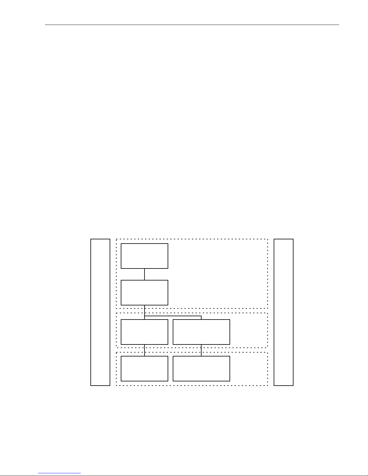
1.1.1 Scope of SCSI-3 standards
Figure 1 uses a representative set of specifications to show the functional partitions and the relationships
among SCSI-3 standards applicable to drives covered by this product manual.
Figure 1. Functional scope of SCSI -3 st andards
SCSI-3 Block
Commands (SBC)
SCSI-3 Primary
Commands (SPC)
SCSI-3
Interlocked
Protocol (SIP)
SCSI-3
Parallel
Interface (SPI)
SCSI-3
Fibre Channel
Protocol (FCP)
Fibre Channel
Physical and Signaling
Interface (FC-PH)
SCSI-3 Architecture Model (SAM)
Common Access Method (CAM)
Commands
Protocols
Interconnects

2 SCSI Interface Product Manual, Rev. J
The functional areas define the scope of each standard as follows:
• SCSI Architecture Model: Defines the S CSI systems model, the functional par titioning of the SCSI-3 standard set and requirements applicable to all SCSI-3 implementations and implementation standards.
• Commands: Implementation standards which define classes including a device model for each class. These
standards specify the required commands and behavior that is common to all devices or unique to a given
class of devices and prescribe the rules to be followed by an initiator when sending commands to a device.
• Common Access Method: Implementation standard which defines a host architecture and set of services for
device ac cess.
• Protocols: Implementation standards which define the rules for exchanging information so that different
SCSI-3 devices can communicate.
• Interconnects: Implementation standards which define the electrical and signaling rules essential for devices
to interoperate over a given physical interconnect.
The diagram of Figure 1 shows how the standards listed below fi t within each cat egory. The standards included
in the diagram are meant to serve as examples and may not reflect the full set of standards currently in force.
1.1.2 Applicable standards
The following ANSI standards should be referenced for more details about SCS I system standards of operation:
• SCSI-3 Architectural Model-2 (SAM-2), T10/1157-D
• Enclosure Services Command Se t, NCITS 305-199x, T10/1212 -D
• SCSI Primary Commands-2 (S PC-2), T10/1236-D
• SCSI Enhanced Parallel Interface-EPI, T10/1143-D
• SCSI-3 Parallel Interface (SPI-3), T10/1302D
• Profile for Parallel SCSI components used in high availability environments, X3T10/1224-TR
• SCSI-3 Medium Changer Commands (SMC), T10/999-D
• SCSI-3 Controller Command Set-2 (SCC-2), T10/1225-D
1.2 General interface description
This Product Manual describes the Seagate Technology, Inc. subset of the SCSI (Small Comput er Systems
Interface) as implemented on the Seagate built drives. The interface is compatible with the S CSI Interface
Specifications listed in Section 1.1.1. The dr ives covered by this product manual are class ified as “Intelligent”
peripherals.
The Seagate SCSI interface described herein consists of a 9 or 18 bit bidirectional bus (8 data + 1 parity or 16
data + 2 parity) plus 9 control signals supporting multiple initiators, disconnect/reconnect, sel f-configur ing host
software, automatic features that relieve the host from the necessity of knowing the physical architecture of the
target (logical block addressing is used), and some other miscellaneous features.
The SCSI physical interface uses either single ended drivers and receivers or differential drivers and receivers
and uses asynchronous or synchronous communication protocols. The bus interface transfer rate for asynchronous or synchronous is g iven in individual dri ve’s Product Manual, Volu me 1. The bus protocol supports multiple initiators, disconnect/reconnect, additional messages plus 6-byte, 10-byte, and 12-byte Command
Descriptor Blocks.
Unless specified otherwise in the individual drive’s Product Manual, Volume 1, the drive is always a target, and
never an initiator. For certain commands, which may or may not be supported by a particular drive model, the
drive must act as an initiator, but does not otherwise do so. For purposes of this specification, “drive” may be
substituted for the word “target” wherever “target” appears.
Note.
In this revision, some new terminology is introduced as taken from the ANSI specifications. In many
instances, the broader scope terms such as “initiator” and “target” are not used, but rather the more
specific terms “Application Client” and “Device Server” appear. In Figure 2, it can be seen tha t several
“application clients” from a single initiator may have one or more task s in queue with several “device
servers” in a single target. A drive c ould be a target or it coul d be one of the device servers as par t of
some larger entity. When reading the des cription, one needs to be able to put the drive of interest in
the proper context in terms of what is shown in Figure 2. For a proper understanding of the operation of
the SCSI protocol, t he ter ms in the SCSI architectural m odel as describe d in AN SI specification T10/
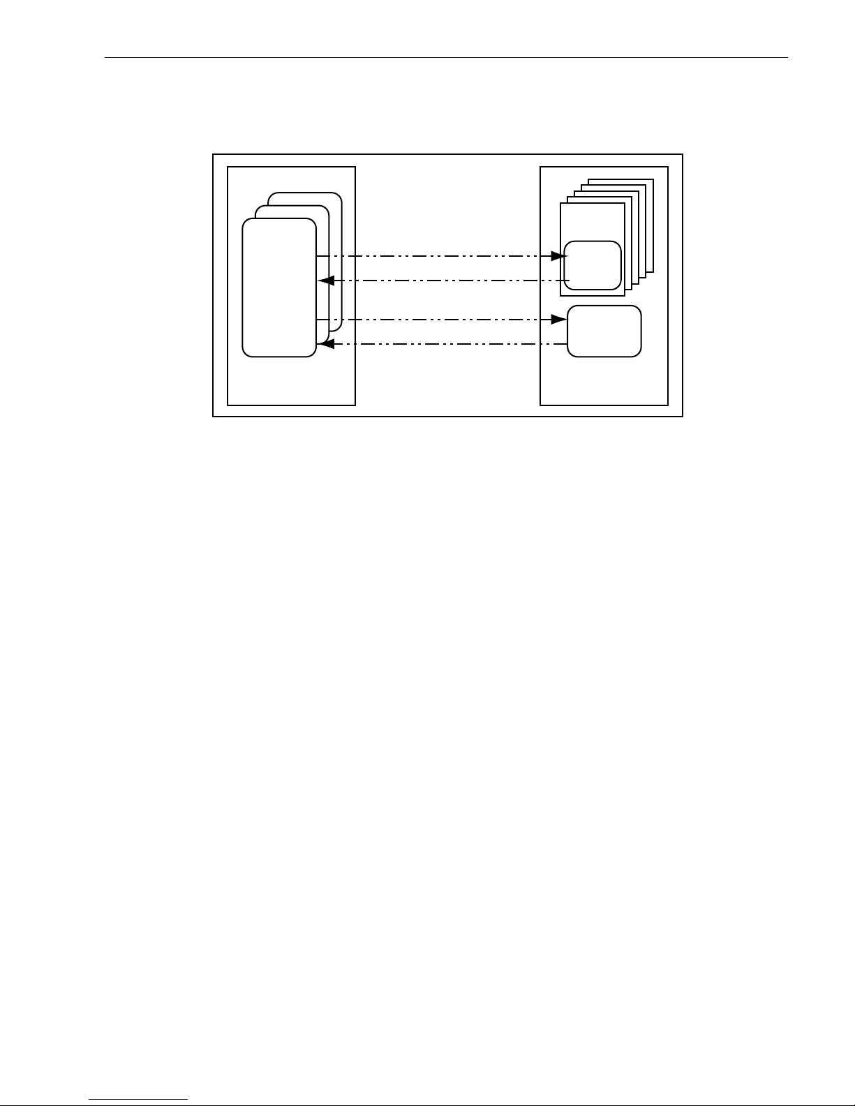
SCSI Interface Product Manual, Rev. J 3
1157-D (SAM-3) should be well unde rstood before reading operation descriptions in any SCS I document. Although a Gl oss ary of term s is provided herein, the definitions may not be adequate for some.
The SAM-3 specification gives a more detailed understanding of some of the new SCSI terminology.
Figure 2. SCSI client-server model
1.2.1 Glossary
aborted command
—A SCSI command that has been ended by abor ting the task created to execute it.
ACA
—Auto Contingent Allegiance (see below).
ACA command
—A command performed by a task with the ACA attribute (see Section 4.6.1).
application client
—An object that is t he source of S CSI commands . An object in this sense is no t a ta ngible
piece of hardware, but may be a single numeric parameter, such as a logical unit number, or a complex entity
that performs a set of operations or services on behalf of another object (see ANSI SAM-2, T10/1157-D).
asynchronous event notification
—A procedure used by targets to notify initiators of events that occur when
a pending task does not exist for that initiator.
auto contingent allegiance
—The condition of a task set following the return of a Check Condition or Com-
mand Terminated status.
blocked (task state)
—The state of a task that is prevented from completing due to an ACA condition.
blocking boundary
—A task set boundary denoting a set of conditions that inhibit tasks outside the boundary
from entering the Enabled state.
byte
—An 8-bit construct.
call
—The act of invoking a procedure.
client-server
—A relationship established between a pair of distributed objects where one (the client) requests
the other (the server) to perform some operation or u nit of work on the client’s behalf (see ANSI SAM-2, T10/
1157-D).
client
—An object that requests a service from a ser ver.
command
—A request describing a unit of work to be performed by a device server.
command descriptor block
—A structure up to 16 bytes in length used to comm unicate a command from an
application client to a device server.
completed command
—A command that has ended by returning a st atu s and service response of Task Com-
plete, Linked Command Complete, or Linked Command Complete (with Flag).
completed task
—A task that has ended by return ing a status and service response of Task Complete. The
actual events comprising the Task Complete response are protocol specific.
Application
Client
Initiator
Task
Manager
Device
Server
Logical
Unit
Target
Device Service Request
Device Service Response
Task Management Request
Task Management Response

4 SCSI Interface Product Manual, Rev. J
confirmation
—A response returned to an object, which signals the completion of a ser vice request.
confirmed protocol service
—A ser vice available at the protocol ser vice interface, which requires conf irma-
tion of completion.
current task
—A task that is in the process of sending messages, sending status, transferring data, or transfer-
ring command data to or from the initiator.
cyclic redundancy check (CRC)
—An error det ecting code used to detect the validity of data that has been
transferred during the current data phase.
destination device
—The SCSI device to which a service delivery transaction is addressed.
See
source
device.
device server
—An object within the logical unit which executes SCSI tasks according to the rules for task
management described in clause 7 of ANSI SAM-2 docum ent , T10/1157D.
device service request
—A request, submitted by an application client, conveying a SCSI command to a
device se rve r.
device service response
—The response returned to an application client by a device server on completion of
a SCSI command.
differential
—A signalling a lternative that em ploys differential drivers and receivers to improve signal-to-noise
ratios and increase maximum cable lengths.
disconnect
—The action that occurs when a SCSI device releases control of the SCSI bus, allowing it to go to
the Bus Free phase.
domain
—An I/O system consisting of a set of SCSI devices that interact with one another by means of a ser-
vice deliv e ry subsystem.
dormant (task state)
—The state of a task that is prevented from starting execution due to the presence of cer-
tain other tasks in the task set.
double tran sition (DT)
—The latching of data on both the as sertion e dge and the negated edge of the REQ
(ACK) signal.
driver
—The circuitry us ed to control the state of the bus.
enabled (task state)
—The state of a task that m ay complete a t any time. Alternat ively, the state of a task that
is waiting to receive the next command in a series of linked commands.
ended command
—A command that has completed or abor t ed.
exception condition
—Any event that causes a SCSI device to enter an auto contingent allegiance or contin-
gent allegiance condition.
faulted initiator
—The initiator to which a Command Ter mi nated or Check Condition status was returned.
faulted task set
—A task set that contained a faulting task.
faulting command
—A command that completed with a status of Check Condition or Command Terminated.
faulting task
—A task that has completed with a status of Check Condition or Command Terminated.
function complete
—A logical unit respo nse indicating that a task management funct ion has finished. The
actual events comprising this response are protocol specific.
hard reset
—A target response to a reset event or a Target Reset in which the target performs the operations
described in Section 4.6.6.
implementation
—The physical realization of an object.
implementation-specific
—A requirem ent or feature that is define d in a SCSI-3 standard but whose imp le-
mentation may be specified by the system integrator or vendor.
implementation option
—An option whose actualization within an implement ation is at the discretion of the
implementor.

SCSI Interface Product Manual, Rev. J 5
initiator
—A SCSI device containing application clients which originate device ser vice and task management
requests to be processed by a target SCSI device.
interconnect subsystem
—One or more physical interconnects which appear as a single pa th for the transfer
of information between SCSI devices in a domain.
intersymbol int e rference (IS I)
—The effect of adjacent symbols on the symbol currently being received.
in transit
—Information that has been sent to a remote object but not yet received.
I/O operation
—An operation defined by an unlinked SCSI command, a series of linked SCSI commands or a
task management function.
I/O process
—An I/O process consists of one initial connection or, if information units are enabled, the
establishment of a nexus, and a zero or more reconnections, all pertaining to a single task or a group of tasks.
An I/O process be gins with the establishment of a nexus. An I/O process normally ends with the B us Free
phase if the quick arbitrate method is disabled. If the quick arbitrate method is enabled, the I/O process
normally ends with a QA Request message.
I T nexus
—A nexus that exists between an initiator and a target.
I T L nexu s
—A nexus that exists between an initiator , a target, and a logical unit. This relationship replaces the
prior I T nexus.
I T L Q nex us
—A nexus between an initiator, a target, a logical unit, and a queue tag following the successful
receipt of one of the queue tag messages. This relationship replaces the prior I T L nexus.
layer
—A subdivision of the architecture constituted by subsystems of the same rank.
linked CDB
—A CDB with the link bit in the control byte set to one.
linked command
—One in a series of SCSI commands executed by a single task, which coll ectively make up
a discrete I/O operation. In such a series, each c ommand has the same ta sk identifier, and all except the last
have the link bit in the CDB control byte set to one.
logical unit
—A target-resident entity which implements a device model and ex ecutes SCSI commands sent by
an application client.
logical unit number
—A 64-bit identifier for a logical unit.
logic a l uni t op ti on
—An option pertaining to a logical unit, whose actualization is at the discretion of the logical
unit implementor.
lower level protocol
—A protocol used to carry the information representing upper level protocol transactions.
mandatory
—The referenced item is required to claim compliance with a standard.
media information
—Information stored within a SCSI device which is non-volatile (retained t hrough a p ower
cycle) and accessible to an initiator through the execution of SCSI commands.
multidrop
—A characteristic of the SCSI bus that allows SCSI devices to be connected to the SCSI bu s without
disrupting the electrical path between the terminat ors.
multimode single-ended (MSE)
—A signalling alternative for multimode SCSI devices that employs MSE driv-
ers and receivers to allow multimode SCSI devices to operate when SE SCSI devices are present on the bus.
nexus
—A relationship b etween an initiator and a target, logical unit, or queue tag that begins with a n initial
connection and ends with the com pletion of the associated I/O process. This relationship is formed as t he
result of a task.
object
—An architectural abstraction or “container” that encapsulates data types, services, or other objects that
are related in some way.
peer-to-peer protocol service
—A ser vice used by an upper level protocol impleme ntation t o exchang e in for-
mation with its peer.
peer entities
—Entities within the same layer.
pendi ng tas k—
A task that is not a current task.

6 SCSI Interface Product Manual, Rev. J
physical interconnect—
A single physical pathway for the transfer of information between SCSI devices in a
domain.
port—
Synonymous with “service delivery port.” A single attachment to a SCSI bus from a SCSI device.
procedure—
An operation that can be invoked through an external calling interface.
protocol—
The rules governing the content and exchange of information passed between distributed objects
through the service delivery subsystem.
protocol option—
An option whose definition within a SCSI-3 protocol standard is discretionary.
protocol service confirmation
—A signal from the l ower level protocol service layer notifying the upper layer
that a protocol service request has completed.
protocol service indication
—A signal from the lower level protocol service layer notifying the upper level that
a protocol transaction has occurred.
protocol service re que st
—A call to the lower level protocol service l ayer to begin a prot ocol service transac-
tion.
protocol service response
—A reply from the upper level protocol layer in response to a protocol service indi-
cation.
queue
—The arrangement of tasks within a task set, usually according to the temporal order in which they were
created.
See
task set.
queue tag
—The parameter associated with a task that uniquely identifies it from other tagged tasks for a logi-
cal unit from the same initiator.
receiver
—A client or server that is the recipient of a service delivery transaction.
reference model
—A standard model used to specify system req uirem ents in an i mpl em entation-indepe ndent
manner.
request
—A transaction invoking a service.
request-response transaction
—An interaction between a pair of dist ributed, cooperating o bjects, consisting
of a request for service submitted to an object followed by a response conveying the result.
request-confirmation transaction
—An interaction between a pair of cooperating objects, consisting of a
request for service submitted to an object followed by a response for the object confirming request completion.
reset event
—A protocol-specific event which may trigger a hard reset response from a SCSI device as
described in Section 4.6.6.
response
—A transaction conveying the result of a request.
SCSI application layer
—The protocols an d proced ures that impleme nt or invoke SCSI commands a nd task
management functions by using services provided by a SCSI protocol layer.
SCSI device
—A device that is connected to a service delivery subsystem and supports a SCS I application
protocol.
SCSI device identifier
—An address by which a SCSI device is referenced within a domain.
SCSI I/O system
—An I/O system, consisting of two or more SCSI devices, a SCSI interconnect an d a SCSI
protocol, which collectively interact to perform SCSI I/O operations.
SCSI protocol layer
—The protocol and services used by a SCSI application layer to transport data represent-
ing a SCSI application protocol transaction.
sender
—A client or server that originates a service delivery transaction.
server
—A SCSI object that performs a service on behal f of a client.
service
—Any operation or function performed by a SCSI-3 object, which can be invoked by other SCSI-3
objects.
service delivery failure
—Any non-recoverable error causing the corruption or loss of one or more service
delivery transactions while in transit.

SCSI Interface Product Manual, Rev. J 7
service delivery por t
—A device-resident interface used by th e application client, device ser ver or tas k manager to enter and retrieve requests and respon ses from the ser vice delivery subsystem. Synonymous with
“port.”
service delive ry subsys tem
—That part of a SCSI I/O system which transmits service requests to a logical
unit or target and returns logical unit or target responses to an initiator.
service delivery transaction
—A request or response sent through the service delivery subsystem.
signal—
(n) A detectable asynchronous event possibly accompanied by descriptive data and parameters.
(v) The act of generating such an event.
source device
—The SCSI device from which a service delivery transaction originates.
See
destination device.
subsystem
—An element in a hierarchically par titioned system which interacts directly only with elements in
the next higher division or the next lower division of that system.
suspended information
—Information stored within a logical unit that is not available to any pending tasks.
target
—A SCSI device which receives SCSI commands and directs such commands to one or more logi cal
units for execution.
task
—An object within the logical unit representing the work associated with a c ommand or group of linked
commands. “Work” includes est ablishing an IT nexus, ITL nexus, ITLQ nexus and all of the other processes
associated with the execution of a command by a Logical Unit. Refer to the defini tions of “object” in this glossary. See also ANSI SAM-2, T10/1157-D, Section 4.9.
task abort event
—An event or condition indicating that the task h as been abor ted by means of a task m an-
agement function.
task address
—An initiator identifies a task to a target using a Task Address. The Task Address object represents either a Tagged Task Address or an Untagged Task Address without regard for the tagged or untagg ed
nature of the Tas k. A Tagged Task A ddress is composed of a Lo gical Unit Identifier and a Tag. An Untagged
Task Addres s is composed of a Logical Unit Identifier.
task completion event
—An event or condition indicating that the task has ended with a service response of
Task Complete.
task ended event
—An event or condition indicating that the task has completed or aborted.
task management function
—A task manage r servic e which can be invoked by an application client to affect
the execution of one or more tasks.
t
ask manag ement request
—A request submitted by an application client, invoking a task management func-
tion to be executed by a task manager.
task management resp onse
—The response retur ned to an application clien t by a task manager on comple-
tion of a task management request.
task manager
—A server within the target which executes task management functions.
task set
—A group of tasks within a target device, whose interaction is dependent on the queuing and auto
contingent allegiance rules of Section 4.6.1.
task slot
—Resources within the logical unit that may be used to contain a task.
task tags
—A Tag is a field containing up to 64 bits that is a component of a Tagged Task Identifier. An initiator
assigns tag values in each Tagged Task Identifier in a way that ensures that the identifier uniqueness requirements stated in ANSI SAM-2, T10/1157-D, Section 4.9 are met.
third-party command
—A SCSI command which requires a logica l unit within the target device to assume the
initiator role and send a SCSI command to a target device.
transaction
—A cooperative interaction between two objects, involving the exchange of information or the exe-
cution of some service by one object on behalf of the other.
unconfirm ed protocol s ervice
—A service available at the protocol service interface, which does not result in
a completion confirmation.

8 SCSI Interface Product Manual, Rev. J
unlinke d com m and
—A SCSI-3 command having the link bit set to zero in the CDB control byte.
upper level p rotocol
—An application-specific protocol executed through services provided by a lower level
protocol.
1.2.2 Keywords
Several keywords are used to differentiate between different levels of requirements and optionality, as follows:
vendor-specific
—Specification of the referenced item is determined by the device vendor.
protocol-specific
—Implementation of the referenced item is defined by a SCSI-3 protocol standard (see Sec-
tion 1.1.1.)
expected
—A keyword used to describe the behavior of the models specified by this standard.
mandatory
—A keyword indicating items required to be implemented as defined by this standard.
may
—A keyword th at ind i cates flexibility o f ch oic e w it h no imp lied preference .
obsolete
—A keyword indicating items that were defined in prior SCSI standards but have been removed from
this standard.
opti on, opt i onal
—Keywords that describe features which are not required to be implemented by this standard.
However, if any optional feature defined by the standard is implemented, it shall be implemented as defined by
the standard.
reserved
—A key word referring to bits, bytes, words, fields, and code values that are set aside for future standardization. Their use and interpretation may be specified by the future extensions to this or other standards. A
reserved bit, byte, word, or field shall be set to zero, or in accordance with a future extension to this standard.
The recipient shall not check reserved bits, bytes, words, or fields. Receipt of reserved code values in de fined
fields shall be treated as an error.
shall
—A keyword indicating a mandatory requirement. Designers are required t o implement all such manda-
tory requirements to ensure interoperability with other standard conformant products.
should
—A keyword indicating flexibility of choice with a strongly preferred alternative. Equiv alent to the phrase
“it is recommended.”
1.3 Physical interface characteristics
The physical interface characteristics (cables, connectors, electrical descriptions, termination requirements,
etc.) for the drives covered by this Interface Manual are found in each individual drive’s Product Manual, Volume 1, since these features are not the same for all drives.

SCSI Interface Product Manual, Rev. J 9
1.4 Summary of SCSI comm and s and messages
Following is an alphabetical table listing the SCSI commands described in this manual . Details are given in
Section 5.0.
Command name Hex code Device type Page number
Change Definition 40 All 78
Format Unit 04 dir. access 80
Inquiry 12 All 87
Log Select 4C A ll 102
Log Sense 4D A ll 110
Mode Select (6 byte) 15 dir. access 112
Mode Select (10 byte) 55 dir. access 116
Mode Sense (6 byte) 1A dir. access 119
Mode Sense (10 byte) 5A dir. access 149
Persistent Reserve In 5E dir.access 154
Persistent Reserve Out 5F dir. access 159
Prefetch 34 dir. access 161
Read 08 dir. access 162
Read Buffer 3C All 164
Read Capacity 25 dir. access 167
Read Defect Data (10 byte) 37 dir. access 169
Read Defect Data (12 byte) B7 dir. access 171
Read Extended 28 dir. access 173
Read Long 3E dir. access 175
Reassign Blocks 07 dir. access 176
Rebuild 81 dir. access 1 78
Receive Diagnostic Results 1C All 181
Regenerate 82 dir. access 185
Release (6 byte) 17 dir. access 187
Release (10 byte) 57 dir. access 188
Report LUNs A0 dir. access 189
Request Sense 03 All 191
Reserve (6 byte) 16 dir. access 200
Reserve (10 byte) 56 dir. access 202
Rezero Unit 01 dir. access 203
Seek 0B dir. access 204
Seek Extended 2B dir. access 205
Send Diagnostic 1D All 206
Start/Stop Unit 1B dir. access 209
Synchronize Cache 35 dir. access 210
Test Unit Ready 00 All 211
Verify 2F dir. access 212
Write 0A dir. acce ss 213
Write and Verify 2E dir. access 214
Write Buffer 3B All 215
Write Extended 2A dir. access 219
Write Long 3F dir. access 221
Write Same 41 All 222
XD Read 52 dir. access 223
XD Write 50 dir . a ccess 225
XD Write Extended 80 dir. access 226
XP Write 51 dir. access 228

10 SCSI Interface Product Manual, Rev. J
Following is an alphabetical summary of the SCSI messages described in this manual. Details are given in
Section 3.5.
Message Name Hex Code Page number
Abort 06 29
Abort Tag 0D 29
Bus Device Reset 0C 29
Clear Queue 0E 30
Command Complete 00 30
Continue I/O Process 12 30
Disconnect 04 30
Extended Message 01 34
Identify 80-FF 31
Ignore Wide Residue 23 39
Initiate Recovery 0F not support ed
Initi a to r Detected Error 05 31
Linked Command Complete 0A 33
Linked Command Complete (with flag) 0B 33
Message Parity Error 09 32
Message Reject 07 32
Modify Data Pointer 01 32, 34 (extended message)
No Operation 08 32
Queue Tag Messages 32
Head of Queue Tag 21 33
Ordered Queue Tag 22 33
Simple Queue Tag 20 33
Release Recovery 10 not supported
Restor e Pointe rs 03 33
Save Data Pointers 02 33
Synchronous Data T ransfer Request 01 33, 34 (extended message)
Target Transfer Disable 1 3 34
Wide Data Transfer Request 01 37 (extended message)

SCSI Interface Product Manual, Rev. J 11
2.0 SCSI bus
This manual discusses only the “logical” and timing characteristics of the SCSI system and interface. The SCSI
bus physical characteristics (voltages, connector configurations, pinouts, etc.) are given in the individual drive’s
Product Manual, Volume 1, in the “Interface requirements” section, which covers all of the inte rface requirements and SCSI features supported by the drive described in the particula r Product Manual being referenced.
Communication on the SCSI Bus is allowed between only two SCSI devices at a time. Some Seagate dr ives
support systems with a maximum of eight SCSI devices including the host computer(s) connect ed to the SCSI
bus. Some Seagate drives support systems with a maximum of sixteen SCSI devices on the SCS I bus. Each
SCSI device has a SCSI ID Bit assigned as shown in Figu re 3. The SC SI ID is assig ned by installing from 0 t o
3 (8 device systems) jumper plugs or 0-4 (16 device systems) jumper plugs onto a connector in a binary coded
configuration during system configuration. Som e dri ve models have an interface that includes the SCSI bus ID
lines, so that the host can se t the dri ve ID over the interface (see individual dri ve’s Product Manual, Volume 1,
“Option/configuration headers” section). Drives that suppor t SCAM protocol (SCSI Configured Automatically)
can have their drive ID assigned via interface also (see Appendix A).
When two SCSI devices communicate on the SCSI Bus, one acts as an initiator and the other acts as a target.
The initiator (typically a host computer) originates an o peration and the target performs the operation . The
drive always operates as a target, unless specified otherwise (i.e., certain commands are suppor ted) in the
individual drive’s Product Manual, Volume 1.
Figure 3. SCSI ID bits
The Host Adapter/Initiator must be identified by one of the eight SCSI Device Addresses. Make sure that none
of the devices on the SCSI bus have duplicate addresses.
Certain SCSI bus functions are assigned to the initiator and certain SCSI bus functions are assigned to the target. The initiator will select a particular target. The target will request the transfer of Command, Data, Status or
other information on the data bus.
Information transfers on the data bus are interlocked and follow a defined REQ/ACK Handshake protocol. One
byte of information will be transferred with each handshake. Synchronous data transfers do not require a onefor-one interlocking of REQ/ACK signals, but the total number of REQ pulses in a particular data transfer event
must equal the total number of ACK pulses. Synchronous data transfer option is described in Paragraph
3.1.5.2 and 3.5.3.2.
The drive supports single initiator, single target; single initiator , m ul tiple target; multi ple initiator, single target; or
multiple initiator, multiple target bus configurations.
DB(7)
DB(6) DB(5) DB(4) DB(3) DB(2) DB(1) DB(0) DATA B US
SCSI ID = 0
SCSI ID = 1
SCSI ID = 2
SCSI ID = 3
SCSI ID = 4
SCSI ID = 5
SCSI ID = 6
SCSI ID = 7
Additional SCSI ID bits for devices that support 16 devices on the SCSI bus.
DB(15)
DB(14) DB(13) DB(12) DB(11) DB(10) DB (9) DB(8) DATA BUS
SCSI ID = 8
SCSI ID = 9
SCSI ID = 10
SCSI ID = 11
SCSI ID = 12
SCSI ID = 13
SCSI ID = 14
SCSI ID = 15

12 SCSI Interface Product Manual, Rev. J
2.1 SCSI bus signals
There are ten control and eighteen data signals, as listed below:
·
BSY
·
C/D
·
MSG
·
DIFFSNS (Multimode) (may sometimes be designated “DIFFSENS”)
·
SEL
·
I/O
·
REQ
·
DB(7-0, P); DB(15-8,P1)
·
ACK
·
ATN
·
RST
Some drive models have a single 80 pin I/O connector that contains additional interface lines that carry drive
configuration select signals. These are peculiar to certain drives and are not SCSI standard signals. These are
described in the individual drive’s Product Manual, Volume 1, but not here.
The 28 SCSI standard signals are described as follows:
BSY (Busy)
—An “OR-tied” signal to indicate the bus is being used.
SEL (Select)
—A signal used by an initiator to select a target, or by a target to reselect an initiator.
C/D (Control/Data)
—A signal driven by a target to indicate whether Control or Data information is on the Data
Bus. Assertion (see Paragraph 2.1.2) indicates Control.
I/O (Input/Output)
—A signal driven by a target to control the direction of data movement on the Data Bus with
respect to an initiator. Assertion indicates input to the initiator. This signal also distinguishes between Selection
and Reselection phases.
MSG (Message)
—A signal driven by a target during the Message phase.
REQ (Request)
—A signal driven by a target to indicate a request for REQ/ACK data transfer handshake.
ACK (Acknowledge)
—A signal driven by an initiator to indicate an acknowledgment for a REQ/ACK data
transfer handshake.
ATN (Attention)
—A signal driven by an initiator to indicate the Attention condition. It is used to request to send
a message out to the target. See Paragraph 3.2.1. If an initiator asserts ATN while asserting SEL it indicates to
the target that the initiator supports messages other than command comple te.
RST (Reset)
—An “OR-tied” signal that indicates the Reset condition.
DIFFSNS (Differential Sense)
—When the drive has high voltage differential SCSI I/O circuits (HVD), the
DIFFSNS signal disables the drive’s differential driver/receiver circuits if the SCSI I/O cable is plugged in
upside down, or if a single-ended SCSI I/O cable is plugged into a differential I/O drive. Disabling the differential I/O drivers/receivers is necessary to prevent burning them out if a grounde d I /O line is c onnect ed to any of
the differential circuit outputs, which are at a positive voltage (+2 V or +3 V) when not disabled.
Multimode—SE or LVD alternative
—“LW” and “LC” models have I/O circuits that can operate either in single-
ended (SE) or low voltage differential mode (LVD). When the interface “DIFFSNS” line is between 0 V and 0.6
V, the drive interface circuits operate single-ended. When “DIFFSNS” is between +0.7 V and +1 .9 V, the drive
interface circuits operate low voltage differential. This arrangement is not intended to allow dynamically changing transmission modes, but rather to prevent incompatible devices from attempting to interoperate. Drives
must operate only in the mode for which the installation and i nterface cabling is designed. Multimode I/O circuits used by “LC” and “LW” devices do not operate at high voltage differential level s and should never be
exposed to high voltage differential environments unless the comma nd mode voltages in the env ironment are
controlled to safe levels for single-ended and low voltage differential devices (see the ANSI SPI-3 specification,
T10/1302D).
DB(7-0,P) and DB(15-8,P1) (Data Bus)
—Sixteen data bi t signals, plus parity bit signals for m a Data Bus.
DB(7) is the most significant bit and has the highest priority during the Arbitration phase (on both eight and sixteen device systems). Bit number significance, and priority decrease downward to D B(0), and then f rom DB 15
down to DB8 (DB0 is higher than DB15). A data bit is defined as one when the signal is asserted and is defined
as zero when the signal is negated.
Data parity DB(P) and DB(P1) is odd
—The use of par ity is a system option. The dr ive always checks parity
on the data bits, but has the capability to enable/disable parity error repor ting to the host. See configuration
selection in the individual drive’s Product Manual, Volume 1. Parity checking is not valid during the Arbitration
phase.
Greater detail on each of the SCSI Bus signals is found in the following sections.

SCSI Interface Product Manual, Rev. J 13
2.1.1 Drive select
For SCSI ID selection, install dr ive select jumpers as shown in configuration selection figure i n the individual
drive’s Product Manual, Volume 1. Refer to the “Physical Interface” section of the individual drive’s Product
Manual for the location of the drive select header. The drive using the eight bit data interface can have one of
eight ID bits selected by installing 0 to 3 jumpers in a binary coded configuration on the drive select header.
Drives using the 16 bit data interface can have one of sixteen ID bits selected by installing 0 to 4 jumpers in a
binary coded configuration on the drive select header. Drives that support SCAM protocol (SCSI Con figured
Automatically) can have their drive ID assigned via the SCSI interface (see Appendix A).
2.1.2 Signal values
Signals may assume true or false values. There are two methods of driving thes e signals. In both cases, the
signal shall be actively driven true, or asserted. In the case of OR-tied drivers, the driver does not drive the signal to the false state, rather the bias circuitry of the bus terminators pulls the signal false whenever it is
released by the drivers at every SCS I device. If any driver is asser ted, then the signal is t rue. In the case of
non-OR-tied drivers, the signal may be negated. Negated means that the signal may be actively driven false, or
may be simply released (in which case the bias circuitry pulls it false), at the option of the implementor.
2.1.3 OR-tied signals
The BSY and RST signals shall be OR-tied only. In the ordinary operation of the bus, these signals are simultaneously driven true by several drivers. No signals other than BS Y, RST, and DB(P) are simultaneously driven
by two or more drivers, and any signal other than BSY and RST m ay employ OR-tied or non-OR-tied d rivers.
DB(P) shall not be driven false during the Arbitration phase. There is no operational problem in mixing OR-tied
and non-OR-tied drivers on signals other than BSY and RST.
2.1.4 Signal sources
Table 1 indicates which type o f SCSI device is allowed to source each signal. All SCSI device drivers that are
not active sources shall be in the pass ive state. Note that th e RS T signal may be sourc ed by any SCS I device
at any time. The drive functions as a target.
2.2 SCSI bus timing
Unless otherwise indicated, the delay time measurements for each SCSI device, defined in Paragraphs 2.2.1
through 2.2.16, shall be calculated from signal conditions existing at that SCSI device’s own SCSI bus connection. Thus, these measurements (except skew delay) can be made without considering delays in the cable.
See Section 2.3 for Fast synchronous transfer option timing.
Table 1: Signal sources
ALL: The signal shall be driven by all actively arbitrating SCSI devices.
Bus phase BSY
Signals
SEL
C/D, I/O,
MSG, REQ ACK/ATN DB(7-0,P) (15-8,P1)
Bus Free None None None None None
Arbitration All Winner None None S CSI ID
Selection I&T Init. None Init. Init.
Reselection I&T Target Target Init. Target
Information transfer phases
Command Target None Target Init. Init.
Data In Target None Target Init. Target
Data Out T arget None Target Init. Init.
Status Target None Target Init. Target
Message In Target None Target Init. Target
Message Out Target None Target Init. Init.

14 SCSI Interface Product Manual, Rev. J
SCSI ID: A unique data bit (the SC SI ID) shall be dr iven by each actively arbitrating SC SI device: the other
seven data bits shall be released (i.e., not driven) by this SCSI device. The parity bit [DB(P), DB(P1)]
may be undriven or dr iven to the true state, but shall never be driven to the false state during this
phase.
I&T: The signal shall be dr iven by the initiator, target, or both, as specified in the Selection phase and
Reselection phase.
Init: If this signal is driven, it shall be driven only by the active initiator.
None: The signal shall be released; that is, not be dr iven by any SCSI device. The bias circuitr y of the bus
terminators pulls the signal to the false state.
Winner: T he signal shall be driven by the one SCSI device that wins arbitration.
Target: If the signal is driven, it shall be driven only by the active target.
2.2.1 Arbitration delay (2.4 µs)
The minimum time a SCSI device shall wait from asserting BSY for arbitration until the Data Bus can be examined to see if arbitration has been won. There is no maximum time.
2.2.2 Assertion period (90 ns)
The minimum time that a target shall assert REQ while using synchronous data transfers. Also, the minimum
time that an initiator shall assert ACK while using synchronous data transfers.
2.2.3 Bus clear delay (800 ns)
The maximum time for a SCSI device to stop driving all bus signals after:
1. The Bus Free phase is detected (BSY and SEL both negated for a bus settle delay).
2. SEL is received from another SCSI device during the Arbitration phase.
3. The transition of RST to assertion.
Note.
For the first condition above, the maximum time for a SCSI device to clear the bus is 1200 ns f rom BSY
and SEL first becoming both negated. If a SCSI device requires more than a bus settle delay to detect
Bus Free phase, it shall clear the bus within a Bus Clear delay minus the excess time.
2.2.4 Bus free delay (800 ns)
The minimum time that a SCSI device shall wait from its detection of the Bus Free phase (BSY and SEL both
negated for a bus settle delay) until its assertion of BSY when going to the Arbitration phase.
2.2.5 Bus set delay (1.8 µs)
The maximum time fo r a SCSI device to assert BSY and its SCSI ID bit on the Data Bus after it detects Bus
Free phase (BSY and SEL both negated for a bus settle delay) for the purpose of entering the Arbitration
phase.
2.2.6 Bus settle delay (400 ns)
The time to wait for the bus to settle after changing cer tain control signals as specified in the protocol d efinitions.
2.2.7 Cable skew delay (10 ns)
The maximum difference in propagation time allowed between any two SCSI bus signals when measured
between any two SCSI devices.
2.2.8 Data release delay (400 ns)
The maximum time for an initiator to release the Data Bus signals following the transition of the I/O signal from
negation to assertion.

SCSI Interface Product Manual, Rev. J 15
2.2.9 Deskew delay (45 ns)
The minimum time required for deskew of certain signals.
2.2.10 Disconnection delay (200 µs)
The minimum time that a target shall wait after releasing BSY before participating in an Arbitration phase when
honoring a Disconnect message from the initiator.
2.2.11 Hold time (45 ns)
The minimum time added between the asser t ion o f R EQ or ACK and t he ch anging of the dat a lines to provide
hold time in the initiator or target, respectively, while using synchronous dat a transfers.
2.2.12 Negation period (90 ns)
The minimum time that a target shall negate REQ while using synchronous data transfers. Also, the minimum
time that an initiator shall negate ACK while using synchronous data transfers.
2.2.13 Reset hold time (25 µs)
The minimum time for which RST is asserted. There is no maximum time.
2.2.14 Selection abor t time (200 µs)
The maximum time that a target (or in itiator) shall take from its most recent detection of being selected (or
reselected) until asserting a BSY response. This timeout is required to ensure that a target (or initiator) does
not assert B SY after a Selection (or Reselection) phase has bee n aborted. This is not t he selection timeout
period; see Sections 3.1.3.5 and 3.1.4.2 for a complete description.
2.2.15 Selection timeout delay (250 ms recommende d)
The minimum time an initiator (or target) should wait for a BSY response duri ng the S election (or Re se lection)
phase before starting the timeout procedure. The drive implements this 250 ms selection timeout delay.
2.2.16 Transfer period (negotiated by Synchronous Data Transfer message)
The minimum time allowed between the l eading edges of successive REQ pulses and of successive ACK
pulses while using synchronous data transfers. (See Sections 3.1.5.2 and 3.5.3.2)
2.3 Fast synchronous transfer option
When devices negotiate a synchronous dat a transfer period of less t han 200 ns they are said to be using “fast
synchronous data transfers.” Devices which negotiate a synchronous dat a transfer period ≥200 ns use timing
parameters specified in Section 2.2. When a fast synchronous data transfer period is negotiated, those specific
times redefined in this section are used; those not redefined remain the same. The minimum synchronous data
transfer period is 100 ns.
2.3.1 Fast assertion period (30 ns)
This value is the minimum time that a target shal l assert REQ while using fast synchronous data transfers.
Also, the minimum time that an initiator shall assert ACK while using fast synchronous data transfers.
2.3.2 Fast cable skew delay (5 ns)
This value is the maximum difference in propagation time allowed between any two SCSI bus signals measured between any two SCSI devices while using fast synchronous data transfers.
2.3.3 Fast deskew delay (20 ns)
This value is the minimum time required for deskew of certain signals while using fast synchronous data transfers.

16 SCSI Interface Product Manual, Rev. J
2.3.4 Fast hold time (10 ns)
This value is the minimum time added between the assertion of REQ or ACK and the changing of the data lines
to provide hold time in the initiator or target respectively, while using fast synchronous data transfers.
2.3.5 Fast negation period (30 ns)
This value is the minimum tim e that a target shall negat e REQ while using fast synchron ous data transfers.
Also, the minimum time that an initiator shall negate ACK while using fast synchronous data transfers.

SCSI Interface Product Manual, Rev. J 17
3.0 Logical characteristics
The operations of the SCSI bus as described in Section 3.0 are suppor ted by the drive, as specified in eac h
individual drive’s Product Manual, Volume 1. The drive always functions as the target unless otherwise stated.
3.1 SCSI bus phases
The drive responds to 8 distinct bus phases.
The SCSI bus can never be in more than one phase at a time.
3.1.1 Bus Fr ee phase
The Bus Free phase indicates that no S CS I device is actively using the S CS I bus an d it is available for subsequent users. In some c ases a target reverts to the B us Free phase t o i ndicate an error condition that it has no
other way to handle. This is called an unexpected disconnect.
SCSI devices shall detect the Bus Free phase after SEL and BSY are both false for at least a bus settle delay.
SCSI devices shall release all SCSI bus signals within a bus clear delay after BSY and SEL are continuously
negated for a bus settle delay. If a SCS I device requires more than a bus settle delay to detect the Bus Free
phase, it shall release all SCSI bus signals within a bus clear delay minus the excess time to de tect the Bus
Free phase. The total time to clear the SCSI bus shall not exceed a bus settle delay plus a bus clear delay.
Initiators normally do not expect Bus Free phase to begin because of the target's release of the BSY signal
except after one of the following occurrences:
1. after a reset condition is detected.
2. after an Abort message is successfully received by a target.
3. after a Bus Device Reset message is successfully received by a target.
4. after a Disconnect message is successfully transmitted from a target (see Section 3.5.3.1).
5. after a Command Complete message is successfully transmitted from a target (see Section 3.5.3.1).
6. after a Release Recovery message is successfully received by a target.
7. after an Abort Tag message is successfully received by a target.
8. after a Clear Queue message is successfully received by a target.
The Bus Free phase may also be entered after an unsuccessful selection or reselection, although in this case it
is the release of the SEL signal rather than the release of the BSY signal that first establishes the Bus Free
phase.
If an initiator detects the release of the BSY signal by the target at any other time, the target is indicating an
error condition to the initiator. The target may perform this transition to the Bus Free phase independent of t he
state of the ATN signal. The initiator shall mana ge this condition as an unsuccessful I/O process term ination.
The target ter m inates t he I/O process by clea ring all pending data and status information for the affected logical unit or target rout ine. The target may optionally prepare sense data that m ay be retrieved by a Request
Sense command. When an initiator detects an unexpected disconnect, it is recommended that a Request
Sense command be attempted to obtain any valid sense data that may be available.
3.1.2 Arbitration phase
The Arbitration phase allows one SCSI device to gain control of the SCSI bus so that it can assume the role of
an initiator or target. The drive arbitrates for the bus as a target implementing resel ection or when perfor ming
AEN (if AEN is implemented). The drive supports arbitration by multiple SCSI devices.
Bus Free phase
Arbitration phase
Selection phase
Reselection phase
Command phase
Data (in and out)
These phases are collectively termed the Information transfer phases
Status (in only)
Message (in and out)

18 SCSI Interface Product Manual, Rev. J
The procedure for a SCSI device to obtain control of the SCSI bus is as follows:
1. The SCSI device shall first wait for the Bus Free phase to occur. The Bus Free phase is detected when
BSY and SEL are simultaneously and continuously negated for a minimum of a bus settle delay. (Implementors note: This bus settle delay is necessary because a transmission line phenomenon known as a
“Wire-OR glitch” may cause BSY to briefly appear negated, even though it is being asserted.)
2. The SCSI device shall wait a minimum of a bus free delay after detection of the Bus Free phase (i.e., after
BSY and SEL are both negated for a bus settle delay) before driving any signal.
3. Following the bus free delay in Step 2, the SCSI device may arbitrate for the SCSI bus by asserting bot h
BSY and its own SCSI ID, however the SCSI device shall not arbitrate (i.e., assert BSY an d its SCSI I D) if
more than a bus settle delay has passed since the Bus Free phase was last observed. (Implementors
Note: There is no maximum delay before asserting BSY and the SCSI ID following the bus free delay in
Step 2 as long as the bus remains in the Bus Free phase. However, SCSI devices that delay longer than a
bus settle delay plus a bus set delay from the time when BSY and SEL are first negated may fail to participate in arbitration when competing with faster SCSI devices.)
4. Af te r waiting a t least an a r b i tration d elay (meas ur e d from its a sse rtio n o f BSY) the SCSI device shall exam-
ine the Data Bus. If a higher priority SCSI ID bit is tr ue on the Data Bus [DB(7 ) is the highest], the SCSI
device has lost the arbitration and the SCSI device must release its signals and return to Step 1. If no
higher priority SCSI ID bit is true on the Data Bus, the SCSI device has won the arbitration and it shall
assert SEL. Any other SCSI device that is par ticipat ing in the Arbitration phase has lost the arbitration and
shall release BSY and its SCSI ID bit within a bus clear delay after SEL becomes true. A SCSI d evice that
loses arbitration may return to Step 1.
5. The SCSI device that wins arbitration shall wait at least a bus clear delay plus a bus settle delay after
asserting SEL before changing any signals.
See also paragraph 3.1.3.6 for arbitration in a SCAM complian t system.
Note.
The SCSI ID bit is a single bit on the Data Bus that corresponds to the SCSI device’s unique SCSI
address. All other seven Data Bus bits shall be released by the SCSI device. Parity is not valid during
the Arbitration phase, DB(P) may be undriven or driven to the true state, but shall not be driven to the
false state.
3.1.3 Selection phase
The Selection phase allows an initiator to select a target for the purpose of initiating some target function (e.g.,
Read or Write command).
Note.
During the Selection phase the I/O signal shall be negated so this phase can be distinguished from the
Reselection phase.
3.1.3.1 Nonarbitrating system
In systems with the Arbitration ph ase not implemented, the ini tiator shall first detect the Bus Free phase and
then wait a minimum of a bus clear delay. Then, except in certain single initiator environments with initiators
employing the single initiator option (see Section 3.1.3.4), the initiator shall assert the des ired target’s SCSI ID
and its own initiator SCSI ID on the Data Bus. After two deskew delays, the initiator shall assert SEL.
3.1.3.2 Arbitrating systems
In systems with the Arbitration phase implemented, the SCSI device that won the arbitration has both BSY and
SEL assert ed and has de layed at least a bus clear delay plus a bus settle delay before ending the Arbitration
phase. The SCSI device that won the arbitration becomes an initiator by releasing I/O. Except in certain single
initiator environments with initiators employing the single initiator option (see Section 3.1.3.4), the initiator shall
set the Data Bus to a value which is the OR of its SCSI ID bit and the target’s SCSI ID bit. The initiator shall
then wait at least two deskew delays and release BSY. The initiator shall then wait at least a bus settle delay
before looking for a response from the target.
3.1.3.3 All systems
In all systems, the target shall determine that it is selected when SEL and its SCSI ID bit are true and the BSY
and I/O signals are false for at least a bus settle delay. T he selected target will examine the Data Bus in order

SCSI Interface Product Manual, Rev. J 19
to determine the SCSI ID of the selecting initiator unless the initiator employed the single initiator option (see
Section 3.1.3.4). The selected ta rget sha ll then a ssert BSY within a select ion abort time of its select ion; this is
required for correct operation of the time-out procedure. In systems with parity implemented, the target shall
not respond to a selection if bad parity is detected. Also, if more than two SCSI ID bits are on the Data Bus, the
target shall not respond to selection. At least two deskew delays after the initiator detects BSY is asserted, it
shall release SEL and may change the Data Bus.
3.1.3.4 Single initiator option
Initiators that do not implement the Reselection phase, and do not operate in the multiple initiator environment,
are allowed to set only the target’s SCSI ID bit during the Selection phase. This makes it impossible for the target to determine the initiator’s SCSI ID.
3.1.3.5 Selection time-out procedure
A Selection time-out procedure is specified for clearing the SCSI bus. If the initiator waits a minimum of a
selection time-out delay and there has been no BSY response from the target, the initiator shall continue
asserting SEL and shall release the Data Bus. If the initiator has not detected BSY to be asserted after at least
a selection abort time plus two deskew delays, the initiator shall release SEL allowing the SCSI b us to go to the
Bus Free phase. SCSI devices shall ensure when responding to selection that the selection was still valid
within a selection abort time of their assertion of BSY. Failure to comply with this requirement could result in an
improper selection (two targets connected to the same initiator, wrong target connected to an initiator, or a target connected to no initiator).
The drive supports systems that implement this procedure.
3.1.3.6 Arbitration and selection under SCAM protocol
SCAM selection
—SCSI bus signals SEL and MSG asserted, with BSY and DB7–DB 0 negated defines the
SCAM selection state. This state merely informs the SCAM devices on the SCSI bus of the start of SCAM protocol. The SCAM selection state comes after an arbitration period wherein a SC AM device wins arbitration.
Any Level 2 SCAM device can star t the SCAM arbi tration/selection states. Selection state d oes not actually
select any device as the regular SCSI selection process does, since no device puts its SCSI bus ID on the data
lines. See SCAM initialization de scription in the SCAM Product Manual, par t number 77767 519. Upon recognizing SCAM selection, a SCAM device’s SCSI interface should respond by asserting SEL and MSG itself, then
interrupting the device’s processor. SCAM target devices shall recognize and respond to SCAM selection
whenever the device has neither been assigned a soft ID nor confirmed its current ID since power-on or a reset
condition.
SCAM initiator
—A SCAM device that is capable of initiating SCAM selection and performing the nor m al functions of a SCSI initiator. These capabilities permit a SCAM initiator to scan a SCSI bus to discriminate between
SCAM tolerant and SCAM devices and assign IDs to the SCAM devices.
SCAM target
—A SCAM device that is capable of recognizin g and respo nding to SCAM selection. Th is capability permits a SCAM target to receive an ID assignment fro m a SCAM initiator. A SCAM target shall have a
current ID, even when a SCAM initiator has not assigned an ID to the SCAM target.
SCAM tolerant
—A SCSI device that does not implement the SCAM protocol but complies with certain requirements specified by the SCAM Product Manual. SCAM initiators can detect SCAM tolerant devices on the SCSI
bus. SCAM tolerant devices may be intermixed with SCAM devices on the SCSI bus. SCAM tolerant (also
called “legacy”) devices retain their own established SCSI bus ID.
Unassigned ID
—The current SCSI ID (se above definition of “current SCSI ID”) that is available to the device
(hard set on the drive), but has not yet been assigned by SCAM protocol to the drive.
SCAM requirements
—Refer to Appendix A and to the SCAM Product Manual for requirements for devices
participating on a SCSI bus that suppor ts the SCAM protocol.
3.1.4 Reselection phase
Reselection is a phase that allows a target to reconnect to an initiator for the purpose of continuing some operation that was previously star ted by the i nitiator but was suspend ed by the ta rget (i.e., the target d isconnec ted
by allowing a Bus Free phase to occur before the operation was complete).

20 SCSI Interface Product Manual, Rev. J
Reselection can be used only in systems that have Arbitration phase implemented.
The drive implements the Reselection phase if the system is capable of supporting Reselection.
ATN during Sel ection imp lies that the host suppor ts messages other than command complete.
Bit 6 of the Identify message indicates that the Disconnected/Reconnect privilege is granted.
ATN not asserted durin g Selec tion mean s that the host doe sn’t suppor t the Identify message, so the Discon-
nected/Reconnect pr ivilege cannot be grant ed. If a target is not granted disconnec t/reconnect privileges, it
shall not disconnect until the current command is completed. None of the Disconnect/Reconnect Control Page
(page 02h) parameters of Mode Select are applicable if disconnect/reconnect privileges are not granted by the
initiator. Operations taking longer than the bus inactivity limit specified do not cause a disconnect.
3.1.4.1 Reselection procedure
Upon completing the Arbitration phase, the winning SCSI device has both BSY and S EL asserted and has
delayed at least a bus clear delay plus a bus settle delay. The winning SCSI device becomes a target by asserting the I/O signal. That device shall also set the Data Bus to a value that is the OR of its SCSI ID bit and the initiator’s SCSI ID bit. The target shall wai t at least two desk ew delays and release BSY. The target shall then wait
at least a bus settle delay before looking for a response from the initiator.
The initiator shall determine that it is reselected when SEL, I/O, and its SCSI ID bit are true and BSY is false fo r
at least a bus settle delay. The reselected initiator may examine the Data Bus to determine the SCSI ID of the
reselecting target.
The reselected initiator shall then assert BSY within a selection abort time of its most recent detection of being
reselected; this is required for correct operation of t he tim eout procedure. In s ystem s with parity implemented,
the initiator shall not respond to Reselection if bad parity is detected. The initiator shall not respond to a Reselection if more than two SCSI ID bits are on the Data Bus.
After the target detects B SY, it shall also a ssert BSY and wait at least two deskew delays and then release
SEL. The target may then change the I/O signal and the Da ta Bus. After the reselected in itiator detects SEL
false, it shall release BSY. The ta rget shall continue assert ing BSY until the target is ready to re linquish the
SCSI bus.
Note.
When the target is asserting BSY, a transmission line phenomenon known as a “Wired-OR glitch” may
cause BSY to appear false for up to a round trip propagation delay following the release of BSY by the
initiator. This is the reason why the Bus Free phase is recognized only after both BSY and S EL are
continuously false for a minimum of a bus sett le delay. Cables long er than 25 meters should not be
used even if the chosen driver, receiver, and cable provide adequate noise margins, because they
increase the duration of the glitch and could cause SCSI devices to inadvertent ly detect the Bus Free
phase.
3.1.4.2 Reselection timeout procedure
This Reselection timeout procedure is specified for clearing the SCSI bus during a Reselection phase. If the
target waits a minimum of a selection timeout period and there has been no BSY response from the initiator,
the target shall continue asserting SEL and I/O and shall release all Data Bus signals. If the target has not
detected BSY to be true after at least a selection abort time plus two deskew delays, the target shall release
SEL and I/O allowing the SCSI bus to go to the Bus Free phase. SCSI devices that respond to Reselection
shall ensure that the Reselection was still valid within a selection abort time of their assertion of BSY. Failure to
comply with this requirement could result in an improper Reselection (two initiators connected to the same target or the wrong initiator connected to a target).
If an initiator times out while waiting to be reselected, the initiator should attempt to select and i ssue Request
Sense to determine if the previous command is:
1. Still in process (Busy Status is returned),
2. Aborted with valid Request Sense data, or
3. Aborted without valid Request Sense data.

SCSI Interface Product Manual, Rev. J 21
3.1.5 Information transfer phases
Note.
The Command, Data, Status, and Message phases are grouped together as information transfer
phases because they are all used to transfer data or con trol information via the D ata Bu s. The actual
contents of the information is beyond the scope of this section.
The C/D, I/O, and MSG signals are used to distinguish between the different information transfer phases (see
Table 2). The target drives these three signals and therefore controls all changes from one phase to another.
The initiator can request a Message Out phase by asserting ATN, while the target can cause the Bus Free
phase by releasing MSG, C/D, I/O, and BSY.
Table 2: Information transfer phases
Key: 0 = False, 1 = Tru e, * = Reser ved
The information transfer phases use one or more REQ/ACK handshakes to control the information transfer.
Each REQ/ACK handshake allows the transfer of one byte of information. During the information transfer
phases BSY shall remain true and SEL s hall re main false. Additionally, during the information transfer phases,
the target shall continuously envelope the REQ /ACK handshake(s) with C/D, I/O, and MSG in such a manner
that these control signals are valid for a bus settle dela y before the assertion of REQ of the first handshake and
remain valid until the negation of ACK at the end of the last handshake.
3.1.5.1 Asynchronous information transfer
The target shall control the direct ion o f informat ion trans fer by means of the I /O signal . W hen I/ O i s tr ue, information shall be transferred from the target to the initiator. When I/O is false, information shall be t ransferred
from th e initiator to the ta r g et.
If I/O is true (transfer to the initiator), the target shall first drive DB(7-0,P)* to their desired values, delay at least
one deskew delay plus a cable skew delay, then assert REQ. DB(7-0,P)* shall remain valid until ACK is true at
the target. The initiator shall read DB(7-0,P)* after REQ is true, then signal its acceptance of the data by
asserting ACK. When ACK becomes true at the target, the target may change or release DB(7-0, P)* and shall
negate REQ. After REQ is false the initiator shall negate ACK. After ACK is false, the target may continue the
transfer by driving DB(7-0,P)* and asserting REQ, as descr ibe d above.
If I/O is false (transfer to the target) the target shall request information by asserting REQ. The initiator s hall
drive DB(7-0,P)* to their desired values, delay at least one deskew delay plus a cable skew delay and assert
ACK. The initiator shall continue to drive the DB(7-0,P)* until REQ is false. When ACK becomes true at the target, the target shall read DB(7-0,P)*, then negate REQ. When REQ becomes false at the initiator, the initiator
may change or release DB(7-0,P)* and shall negate ACK. The target may continue the transfer by asserti ng
REQ, as described above.
Signal
Phase name Direction of transfer CommentMSG C/D I/O
0 0 0 Data out Initiator to ta rg e t
Data
Phase
0 0 1 Data In Initiator from target
0 1 0 Command Initiator to targ e t
0 1 1 Status Initiator from target
1 0 0 *
1 0 1 *
1 1 0 Message Out Initiator to target
Message
Phase
1 1 1 Message In Initiator from target
*
And where applicable, DB(15-8, P1).

22 SCSI Interface Product Manual, Rev. J
3.1.5.2 Synchronous data transfer
Synchronous data transfer may be used only in the data phase if previously agreed to by t he i nitiator and target
through the message system (see Synchronous Data Transfer Request message in Section 3.5.3.2). The messages determine the use of synchronous mode by both SCSI devices and establish a REQ/ACK offset and a
transfer period.
The REQ/ACK offset specifies the m ax imum num ber of RE Q pulses that can be s ent by the t arget in a dvance
of the number of ACK pulses received from the i nitiator, establishing a paci ng mechanism. If the number of
REQ pulses exceeds the number of ACK pulses by the REQ/ACK offset, the target shall not assert REQ until
the next ACK pulse is received. A requirement for successful completion of the data phase is that the number
of ACK and REQ pulses be equal.
The target shall assert the REQ signal for a minimum of an assertion peri od. The target shall wait at least the
greater of a transfer period from the last transition of REQ to true or a minimum of a negation period from the
last transition of REQ to false before asserting the REQ signal.
The initiator shall send one pulse on the ACK signal for each REQ pulse received. The ACK signal may be
asserted as soon as the leading edge of the corresponding REQ pul se has been received. The initiator shall
assert the ACK signal for a minimum of an asser tion period. The initiator shall wait at least the greater of a
transfer period from the last transition of ACK to true or for a minimum of a negation period from the last transition of ACK to false before asserting the ACK signal.
If I/O is asserted (transfer to the initiator), the target shall first drive DB(7-0,P)* to their desired values, wait at
least one deskew delay plus one cable skew delay, then assert REQ. DB(7-0,P)* shall be hel d valid for a minimum of one deskew delay plus one cable skew delay plus one hold time after the assertion of REQ. The target
shall assert REQ for a minimum of an assertion period. The target may then negate REQ and change or
release DB(7-0,P).* The initiator shall read the value on DB(7-0,P)* within one hold time of the transition of
REQ to true. The initiator shall then respond with an ACK pulse.
If I/O is negated (transfer to the target), the initiator shall transfer one byte for each REQ pulse received. After
receiving a REQ pulse, the initiator shall first drive DB(7-0,P)* to their desired values, delay at least one
deskew delay plus one cable skew delay, then asser t ACK. The initiator shall hold DB(7-0,P)* valid for at least
one deskew delay plus one cable skew delay plus one hold time after the assertion of ACK. The initiator shall
assert ACK for a minimum of a n assertion period. The initiator may then n egate ACK and may change or
release DB(7-0,P).* The target shall read the value of DB (7-0,P)* wi thin on e hold time of the transition o f ACK
to true.
3.1.6 Command phase
The Command phase allows the target to request command information from the initiator.
The target shall assert the C/D signal and negate the I/O and MSG signals during the REQ/ACK handshake(s)
of this phase.
3.1.7 Data phase
The Data phase is a term that encompasses both the Data In phase and the Data Out phase.
3.1.7.1 Data in phase
The Data In phase allows the target to request that it send data to the initiator.
The target shall assert the I/O signal and negate the C/D and MSG signals during the REQ/ACK handshake(s)
of this phase.
3.1.7.2 Data out phase
The Data Out phase allows the target to request that data be sent to it from the initiator.
The target shall negate the C/D, I/O, and MSG signals during the REQ/ACK handshake(s) of this phase.

SCSI Interface Product Manual, Rev. J 23
3.1.8 Status phase
The Status phase allows the target to request that it send status information to the initiator.
See Section 4.3 for details.
The target shall assert C/D and I/O and negate the MSG signal during the REQ/ACK handshake of this phase.
3.1.9 Message phase
The Message phase is a term that references either a Message In or a Message Out phase. Multiple messages
may be sent during either phase. Multiple byte messages shal l be wholly contained with a single message
phase. Messages supported by a p articular drive are l isted in the in dividual dri ve’s Product Manual, Volume 1,
for that drive.
3.1.9.1 Message in phase
The Message In phase allows the target to request that it send message(s) to the initiator.
The target shall assert C/D, I/O, and MSG during the REQ/ACK handshake(s) of this phase.
3.1.9.2 Message out phase
The Message Out phase al lows the target to request that message(s ) be sent from the initiator to the target.
The target may invoke this phase at its convenience in response to the Attention c ondition (see Section 3 .2.1)
created by the initiator.
The target shall assert C/D and MSG and negate I/O during the REQ/ACK handshake(s) of this phase. The target shall handshake byte(s) in this phase until ATN goes false, unless an error occurs (see Message Reject, in
Section 3.5.2).
If the target detects one or more parity error(s) on the m essage byte(s) received, it may indicate its desire to
retry the message(s) by assert ing REQ after detecting AT N has gone false and before changing to any other
phase. The initiator, upon detecting this condition, shall resend all of the previous message byte(s) sent during
this phase. When resendin g m ore than one message byte, the initiator shall as sert ATN before asserting ACK
on the first byte and shall maintain A TN asserted until the last byte is sent as described in Section 3.2.1.
If the target receives all of the message byte(s) successfully (i.e., no parity errors), it shall indicate that it shall
not retry by changing to any information transfer phase other than the Message Out phase and transfer at least
one byte. The target may also indicate that it has successfully received the message byte(s) by changing to the
Bus Free phase (e.g., Abort or Bus Device Reset messages).
3.1.10 Signal restrictions betw een phases
When the SCSI bus is between two information transfer phases, the following restrictions shall apply to the
SCSI bus signals:
1. The BSY, SEL, REQ, and ACK signals shall not change.
2. The C/D, I/O, MSG, and Data Bus signals may change. When switching the Data Bus direction from Out
(initiator driving) to In (target driving), the target shall delay driving the Data Bu s by at least a dat a rel ease
delay plus settle delay after asserting the I/O signal and the initiator shall release the Da ta Bus no later
than a data release delay after the transition of the I/O signal to true. When switching the Data Bus direction from In (target dri ving) to Out (initiator driving ), the target shall release t he Data Bus no later than a
deskew delay after negating the I/O signal.
3. The ATN and RST signals may change as defined under the descriptions for the Attention condition (see
Section 3.2.1) and Reset condition (see Section 3.2.2).
3.2 SCSI bus asynchronous conditions
The SCSI bus has two asynchronous conditions: the Attention condition and the Reset condition. These conditions cause the SCSI device to perform certain actions and can alter the phase sequence.
3.2.1 Attention condition
The Attention condition allows an initiator to inform a target that the initiator has a message ready. The target
gets this message at its convenience by performing a Message Out phase.

24 SCSI Interface Product Manual, Rev. J
The initiator creates the Attention condition by asserting ATN at any time except during the Arbitration or Bus
Free.
The initiator shall asser t the AT N signal two deskew delays before negating the ACK signal for the last byte
transferred in a bus phase for the attention condition to be honored before transition to a new bus phase.
Asserting the ATN signal later mi ght not be honored until a later bus pha se and then may not result in the
expected action. The initiator shall negate the ATN signal two deskew delays before asserting the ACK signal
while transferring the last byte of the message. If the target detects that the in itiator failed to meet this req uirement, then the target shall go to Bus Free phase (see unexpected Bus Free in Section 3.1.1).
The drive responds with Message Out phase as follows:
1. If ATN occurs during a Data phase, Message Out occurs at a convenient time. It may not occur until several
logical blocks after ATN is first asserted.
2. If ATN occurs dur ing a Command ph ase, Message Out occurs after transfer of all Command D escriptor
Block bytes has been completed.
3. If ATN occurs during a Status phase, Message Out occurs after the status byte has been acknowledged by
the initiator.
4. If ATN occurs duri ng a M es sage In Phase, Message Out o ccurs aft er the last byte of the c urrent m es sage
has been acknowledged by the initiator.
5. If ATN occurs during a Selection or Res election phase, Message Out occ urs im m ediately a fter t hat S election or Reselection phase. In the Reselection case, the drive enters the Message Out phas e after it has
sent its Identify message for that Reselection Phase.
The initiator shall keep AT N asserted if more than one byte is to be t ransferred. The initiator may negate the
ATN signal at any time except while the ACK signal is asserted duri ng a Message Out phase. Recommended
practice is that the initiator negates ATN while REQ is true and ACK is false during the last RE Q/ACK handshake of the Message Out phase.
3.2.2 Reset condition
The Reset condition is used to immediately clear all SCSI devices from the bus. This condition shall take precedence over all other phases and conditions. During the Reset condition, the state of all SCSI bus signals
other than RST is not defined.
The drive never asserts the Reset signal.
All SCSI devices shall release all SCSI bus signals (except RST) within a bus clear d elay of the transition of
RST to true. The Bus Free phase always follows the Reset condition.
Drives that operate in accordance with this specification impleme nt only the “hard” Res et option. Upon detec-
tion of the Reset condition, the drive shall:
1. Clear all uncompleted commands,
2. Release all SCSI device reservations,
3. Return any SCSI device operating modes (Mode Select, etc.) to their default or last saved conditions.
4. Activate Unit Attention Condition for all Initiators.
3.3 SCSI bus phase sequences
The order in which phases are used on the SCSI bus follows a prescribed sequence.
In all systems, the Reset condition can abort any phase and is always followed by the Bus Free phase. Also,
any other phase can be followed by the Bus Free phase.
3.3.1 Nonarbitrating system
For systems in which the Arbitration phase is not implemented, the allowabl e sequences are shown in Figure 5.
The normal progression is from the Bus Free phase to Selection, and from Selection to one or more of the
information transfer phases (Command, Data, Status, or Message).

SCSI Interface Product Manual, Rev. J 25
3.3.2 Arbitrating systems
For systems in which the Arbitration phase is implemented, the allowable sequences are shown in Figure 4.
The normal progression is from the Bus Free phase to Arbitration, from Arbitration to Selection or Reselection,
and from Selection or Reselection to one or mo re of the in formation transfer phases (Comman d, Da ta, Status,
or Message). Se e ANSI do cument T10/1302D, section 11.1.2.2.1, for a description of Quick Arbitration (QA)
phase.
3.3.3 All systems
There are no restrictions on the sequences between information transfer phases. A phase type may even be
followed by the same phase type (e.g., a Data phase may be followed by another Data phase).
*Data phase must follow a command phase except after reselection phase
Figure 4. Phase sequences with arbitration
Figure 5. Phase sequences without arbitration
3.4 SCSI poi nt ers
The drive supports systems that use the pointer philosophy described in the following paragraphs.
Consider the system shown in Figure 6 in which an initiator and target communicate on the SCSI bus in order
to execute a command.
Figure 6. Simplified SCSI sys tem
Reset Condition
Bus
Free
Phase
Arbitration
Phase
Selection or
Reselection
Phase
Command or
Data*
or Status or
Message Phase
Reset Condition
Bus Free
Phase
Selection
Phase
Command or Data
or Status or
Message Phase
Function
Origin
Initiator
Path
Control
Initiator
Target
Path
Control
Target
Function
Execution
SCSI
Bus

26 SCSI Interface Product Manual, Rev. J
The SCSI architecture provides for sets of pointers to be kept within each initiator Path Control area (see Figure 6). These pointers are in sets of three pointers per set. The pointers in each set point to three storage area
sections in the initiator. The three sections contain the following information:
1. A command from initiator to target.
2. Status (from target) associated with the command.
3. Data (to/from target) associated with the command.
Of these three-pointer sets there are two types:
1. Current (active) pointers (one set per initiator only).
2. Saved pointers (one or more sets per initiator, up to seven sets total).
The use of these two types of pointers is described in the following paragraphs.
3.4.1 Curre nt pointers
Current Pointers represent the current state of the interface between the initiator a nd the target the i nitiator is
currently connected to and servicing. The pointers for the current command remain in the initiator Current
Pointer registers from the time they are put there after the completion of all activities associated with the previous command until the logic of the Initiator dict ates a new command shall be executed. Normally, successful
receipt by the initiator of good status associated with current command t r iggers t he initiator to insert a new set
of the three “current” pointers for the next command. The initiator does not wait for the Command Complete
signal before deciding whether to retr y the c urrent comm and or t ransfer in new command pointers. If the c urrent command was never satisfactorily completed, the initiator logic m ay dictate that some special response
action be taken, such as restoring the values in the current pointer registers to their beginning values so the
current command can be resent (s ee note following), or sending a com mand such as a Request S ense command to the target, or the initiator could ignore the unsatisfact orily completed command and send the next originally scheduled command.
Note.
For example, if the drive detects a parity error in the data out from the c urrent command , it sends the
“Restore Pointers” message to the initiator. In t his case, the Restore P oi nters request causes the initiator to restore the current pointers to the values existing at the beginning of the current command so the
current command can be resent. The “beginning” po inter values point to the first byte of the current
Command Descripto r Block, the first byte of the area set aside for status to be returned and the first
byte of the area set aside for data associated with the current com mand. (See Paragraph 3.4.2 for a
detailed description of operations resulting from the Restore Pointers message).
3.4.2 Saved pointers
Saved pointers point to initiator storage locations where command, status and data information are stored for a
command that was saved at some point i n the past. There is one set of saved pointers for t he current command
for each target on the interface bus that is currently active (whether or not it is currently connected to the initiator). The saved command pointer al ways points to the first byte of t he Com mand De scriptor Block (see Paragraph 4.2) for the “current” command for each target, the saved status pointer always points to the first byte of
the area used for the status associated with the command, and t he s aved data pointer points to some l ocation
(not necessarily the beginning) in the area use d for data associated with the command. When a t arget disc onnects the initiator saves the current pointers. Before a target disconnects it may send a Save Data Pointers
message to the initiator, which copies the data pointer that is for the current command for that target into the
location set aside for the target’s saved pointers. When a target reconnects, the initiator performs a restore
pointers operation that copies the saved pointers for the reconnected target into the initiator current pointer registers so that the current command for that target may continue its operation from where it left off bef o re disconnecting. If the target had sent a Save Data Pointer message previously, the current data pointer points to the
place in the data store area where operations left off. The data pointer otherwise points to the beginning of the
data area, unless the data pointers were modified by a Modify Data Pointers message from the target prior to
disconnecting. The Mo dify Data Pointers message adds a value to the dat a pointer that allows data to be
taken, upon reconnection, from a location before or after the last byte transferred location.

SCSI Interface Product Manual, Rev. J 27
3.5 Message system specification
The message system allows communication between an initiator and target for the purpose of in terface management. For Seagate drives, the Logical Unit Number (LUN) (see Section 4.2.2) ha s always been zero. This
may not be true on all future drives.
3.5.1 General message protocol
A message may be one, two, or multiple bytes in length. One or more mess ages may be sent du ring a single
Message phase, but a message may not be split over Message phases. The initiator is required to end the
Message Out phase (by negating ATN ) when it sends certain message s identified in Table 3. One-byte, Tw obyte, and extended message formats are defined. The first byte of the message deter mines the format as follows:
One-Byte messages c onsist of a single byte transferred during a Message ph ase. The Message code of the
byte determines the message to be performed as defined in Table 3. The Identify mess age is a one byte code,
but its format is different.
Two-byte messages consist of two consecutive bytes transferred during a Message phase. The value of the
first byte determines the message to be performed as def ined in Table 3. The second byte is a parameter byte
that is used as defined in the message descriptions in Section 3.5.2.
See Section 3.5.3.1 for details on the one and two byte messages.
Extended messages consist of from three to 7 bytes transferred during the Message phase. The extended
message includes a three byte header and up to 4 extended message argument bytes. See Section 3.5.3.2 for
details of the extended messages.
Message code Message format
00h One-Byte Message (Task Complete)
01h Extended Messages
02h - 1 Fh One-Byte Me ssage
20h - 2Fh Two-Byte Messages
30h - 7Fh Reserved
80h - FFh One-Byte Message (Identify)

28 SCSI Interface Product Manual, Rev. J
3.5.2 Messages—General
The messages suppor ted by the various drives are listed in a table in the individual dri ve’s Product Manual,
Volume 1. Table 3 lists Messages that are defined by the SCSI protocol. The message code values are given a
direction specification (In-Out). Detailed descriptions follow the table. Messages other than those supported by
a drive are answered by the drive with a Message Reject message.
Table 3: Message codes
KEY: In = Target to initiator Out = Initiator to target
Yes = Initiator sha ll negate ATN before last ACK of message
No = Initiator may or may not negate ACK before last ACK of message (see Section 3.2.1, Attention Condi ti on)
— = Not applicable
*** = Extended message (see Tables 6 throu gh 9)
80h+ = Codes 80h through FFh are used for Identify m essages
[1] = The drive does not resend (Retry) the origi nal message
[2] = See Table 4.
Code Message name Direction
Negate ATN
before last ACK
01h*** Ex te nded Me ssag e In Out Yes
06h Abort Task Set Out Yes
0Dh Abor t Task Out Yes
0Ch Bus Device Reset Out Yes
0Eh Clear Task Set Out Yes
00h Task Complete In —
04h Disconnect In —
80h–FFh [2] Identify In —
80h–FFh [2] Identify Out No
23h Ignore Wide Residue (Two Bytes) In —
0Fh Initiate Recovery In Out Yes
05h Initiator Detected Error Out Y es
0Ah Linked Command Complete In —
0Bh Linked Command Complete (With Flag) In —
09h Message Parity Error Ou t Yes
07h Message Reject [1] In Out Yes
*** Modify Data Pointer In —
08h No Operations Out Yes
Queue Tag Messages (Two Bytes)
21h Head of Queue Ta g Out No
22h Ordered Queue T ag Out No
20h Simple Queue Tag In Out No
10h Release Recovery Out Yes
03h Restore Pointers In —
02h Save Data Pointer I n —
*** Synchronous Data Transfer Request In Out Yes
*** Wide Data Transfer Request In Out Yes
12h Continue Task Out Yes
13h Target Transfer Disable Out Yes
14h–1Fh Reserved
24h–2Fh Reserved for two-byte messages
30h–7Fh Reserved

SCSI Interface Product Manual, Rev. J 29
The first message sent by the initiator after the Selection phase shall be an I dentify, Abort, or Bus Device Reset
message. If a target receives any other message, it shall go to Bus Free phase (unexpected Bus Free).
If the first message is an Identify message, then it may be immediately followed by other messages, such as
the first of a pair of S ynchronous Da ta Transfer Request messages. If tagged queuing is used , the queue tag
message immediately follows the Identify message. The Identify message establishes a logical connection
between the initiator and the specified logical unit known as an I T L nexus.
After the Reselection phase, the target’s first message shall be Identify. This allows the I T L nexus to be reestablished. Only one logical unit shall be identified for any connection; if a target receives a second Identify message with a logical unit number other than zero during a connection, it shall go to Bus Free phase (unexpected
Bus Free).
Whenever an I T L nexus is established by an initiator that is allowing disconnection, the initiator shall ens ure
that the active pointers are equal to the saved pointers for that particular logical unit. An implied restore pointers operation shall occur as a result of a reconnection.
3.5.3 Message details
SCSI message details are defined in the following paragraphs.
3.5.3.1 One and two byte messages
Abort Task Set (06h)
The Abort Task Set message is sent from the initiator to the target to clear the present task plus any queued
task for the I T L nexus. The target shall go to the Bus Free phase following successful receipt of this message.
Pending data, status, and task sets for any other I T L nexus shall not be cleared.
If only an I T nexus has been established, the target shall go to the Bus Free phase. No status or message
shall be sent for the task and the task set shall not be affected.
It is not an error to issue this message to an I T L nexus that does not currently have an active task or task set.
Transmission of this message shall terminate any extended contingent allegiance condition that may exist
between the I T L nexus.
Notes.
1. The B us Device Reset, Clea r Queu e, Abort Task Set, and Abort Tas k m es sages provide a means to clear
one or more tasks prior to normal termination. The Bus Device Reset message clears all tasks for all initiators on all logical units of the target. The Clear Queue message clears all tasks for all initiators on the specified logical unit of the target. The Ab ort Task Set message clears al l tasks for the selecting in itiator on the
specified logical unit of the target. The Abort Task message clears the current task only.
2. It is perm issible for an initiator to select a target that is currently disconnected for the purpose of sending
one of the above message sequences.
Abort Task (0Dh)
The target shall go to the Bus Free phas e following successful receipt of the Ab ort Task message. The target
shall clear the current task for the I T L nexus. If the target has already started execution of the task, the execution shall be halted. The medium con tents may have been modified before the execution was halted. In either
case, any pending status or data for the task shall be cleared and no status or ending message shall be sent to
the initiator. Pending status, data, and tasks for other queued tasks or executing tasks shall not be affected.
Execution of other tasks queued for the I T L nexus shall continue in the normal manner.
Bus Device Reset (0Ch)
The Bus Device Reset message is sent from an initiator to direct a target to clear all current tasks on that SCSI
device. This message forces a hard reset condition to the selected SCS I drive. The target shall go to t he Bus
Free phase following successful receipt of this message. The target s hall create a Un it Attention con dition for
all initiators (See Section 4.6.5).

30 SCSI Interface Product Manual, Rev. J
Clear Task Set (0Eh)
The target shall go to the Bus Free phase following successful receipt of the Clear Task Set message. The target shall perform an action equivalent to receiving a se rie s of Abort Task Set messages from each initiator. All
tasks from all initiators in the task set for the specifi ed l ogica l unit shall be cleared fro m t he task set. All executing tasks shall be halted. The m edium may have been altered by par tially executed commands. All pending
status and data for that logical unit for all initiators shall be cleared. No status or ending message shall be sent
for any of the outstanding tasks. A unit attention condition shall be generated for all other initiators with tasks
that either had been executing or were queued in a task set for execution for that logical unit. When reporting
the Unit Attention condition the additional sense code shall be set to Task Set Cleared by Another Initiator.
Task Complete (00h)
The Task Complete message is sent from a target to an initiator to indicate that t he execution of a command (or
series of linked commands ) has ter minated and that valid status h as been s ent to the in itiator. After successfully sending this message, the target shall go to the Bus Fr ee phase by releasing BSY. The target shall consider the message transmission to be successful when it detects the negat ion of ACK for the Task Com plete
message with the ATN signal false.
Note.
The command may have been exec ut ed suc cessfully or unsuccessf ully as indicated in the status.
Continue T ask (12h)
The Continue Task message is sent from the initiator t o the target to rec onnect to a task. Th is message shal l
be sent in the same Message Out phase as the Identify message.
Implementors Note: Thus the Message Out phase following Selection phase consists of the Identify, Task
Attribute (if any), and Continue Task messages.
The purpose of the Continue Task message is to distinguish a valid initiator reconnection from an incorrect initiator reconnection (see Section 4.10).
If the target expects a significant delay before it will be ready to continue processing the rec onnected task, it
may attempt to free the SCSI bus by sending a Disconnect message to the initiator. The initiator may reject the
disconnection attempt by responding with Message Reject message.
It is an error for the initiator to send this m essage on an initial connec tion (i.e., there is no tas k for the nexus)
and the target shall go to the Bus Free phase (see unexpected disconnect in Section 3.1.1).
Initiators should avoid sending this message to targets w hich have not implemented this mess age. Such targets may not respond as described in this section. An initiator can determ ine whether a target implements this
message by examining the TrnDis bit in the standard Inquiry data (see Table 49).
Disconnect (04h)
The Disconnect message is sent from a t arget to inform an initiator that the present connect ion is going to be
broken (the target plans to disconnect by releasing the BSY signal), but that a later reconnect will be required
in order to complete the current task. This message shall not cause the initiator to save the data pointer. After
successfully sending this message, the target shall go to the Bus Free phase by releasing the BSY signal. The
target shall consider the message transmission to be successful when it detects the negation of the ACK signal
for the Disconnect message with the ATN signal false.
Targets which break data transfers into multiple connections shall end each successful connection (except possibly the last ) with a S ave D a ta Poin t–Disconnect message sequence.

SCSI Interface Product Manual, Rev. J 31
Identify (80h - FFh)
The Identify message (Table 4) is sent by either the initiator or the target to establish an I T L nexus.
The Identify bit shall be set to one to specify that this is an Identify message.
A Disconnect Privilege (DiscPriv) bit of one specifies that the initiator has granted the target the privilege of dis-
connecting. A DiscPriv bit of zero specifies that the target shall not disconnect. Those drive models that do not
implement this feature must set this bit to zero. This bit is used in connection with the Disconnect Immediate
(DImm) bit in the Disconnect/Reconnect Mode Page.
Note.
If an initiator selects a drive using the SCSI -1 Singl e In itiator Opt ion, the drive shall not attempt to disconnect from that task, regardless of the state of the Disconnect Privilege bit in the Identify message (if
sent).
A logical unit target (LUNTAR) bit of zero specifies that the Identify message is directed to a logical u nit. A
LUNTAR bit of one specifies t hat the Ident ify message is dire cted to a targe t routine that does not involve the
logical unit. This bit is not supported by the drive and will always be interpret ed as a 0.
The logical unit number target routine number (LUNTRN) field specifies a logical unit number if the LUNTAR bit
is zero. The LUNTRN field specifies a target routine number if the LUN TAR bit is on e. Only the Inquiry a nd
Request Sense commands are valid for target routines. If a target receives any other command for a target routine, it shall return Check Condition status and shall set the sense key to Illegal Request.
An invalid LUNTRN field terminates the command with a Check Condition, and in response to a Request
Sense command the drive retur ns sense data with the sense key set to Illegal Request and the additiona l
sense code set to Logical Unit Not Supported.
An Identify message is invalid if a reserved bit is s et to one or if the LUNTAR bit is set to one and t he target
does not implement target routines. A device may respond to an invalid Identify message by immediately sending a Message Reject message or by returning Check Condition status. If a Check Condition status is returned,
the sense key shall be set to Illegal Request and the additional sense code shall be set to Invalid Bits in Identify
Message Field.
If a valid Identify message has not yet been received for the current nexus, the drive returns a Message Reject
message and goes to the Bus Free phase (see Unexpected Disconnect, in Section 3.1.1).
Only one logical unit number or target routine number shall be identified per task. The initiator may send one or
more Identify mess ages during a connect ion. A second Ide ntify message with a d ifferent value in eithe r the
LUNTAR bit or LUNTRN field shall not be issued before a Bus Free phase has occurred; if a t arget receives a
second Identify message with a different value in either of these fields, it shall go to Bus Free phase (unexpected BUS switch to another task. See the DTDC field of the Disconnect-Reconnect Control Page (Table 91)
for additional controls over disconnection.
An implied Restore Pointers message shall be performed by the initiator prior to the assertion of the ACK signal on the next phase for an Identify message sent during reconnection.
Initiator Detected Error (05h)
The Initiator Detected Error message is sent from an initiator to inform a target that an error has occurred that
does not preclude the target from retrying the operation. The source of the error may either be related to previous activities on the SCSI bus or may be inter nal to the i nitiator and unrelated to any previous SCSI bus activity. Although present pointer integrity is not assured, a Restore Pointers message or a disconnect followed by a
reconnect, shall cause the pointers to be restored to their defined prior state.
T able 4. Identify message f ormat
Bit
Byte
76543210
0 Identify DiscPriv LUNTAR LUNTRN

32 SCSI Interface Product Manual, Rev. J
Message Parity Error (09h)
The Message Parity Error message is sent from the initiator to the target to indicate that the last message byte
it received had a parity error.
In order to indicate its intentions of sending this mes sage, the initiator shall asser t the ATN signal prior to its
release of the ACK signal for the REQ/ACK handshake of the message that has the p arit y error. This provides
an interlock so that the target can determine whi ch message has the parity error. If the target receives this
message under any other circums tance, it shall signal a cat ast rophic error condition by releasing the BSY signal without any further information transfer attempt (see Section 3.1.1).
Message Reject (07h)
The Message Reject message i s sent from ei ther the i nitiator or target to indicate that the last mes sage byte it
received was inappropriate or has not been implemented.
In order to indicate its intentions of sending this mes sage, the initiator shall asser t the ATN signal prior to its
release of the ACK signal for the REQ/ACK handshake of the message byte that is to be rejec ted. If the target
receives this message under any other circumstance, it shall reject this message.
When a target sends this message, it shall change to Message In phase and send this message prior to
requesting additional message bytes from the initiator. This provides an interlock so that the initiator can determine which message byte is rejected.
Note.
After a target sends a Message Reject message and if the ATN signal is still asserted, then it returns to
the Message Out phase. The subsequent Message Out phase begins with the first byte of a message,
not the middle of the previous message.
Modify Data Pointer (01h)
See Paragraph 3.5.3.2, Extended Message.
No Operation (08h)
The No Operation message is sent from an i nitiator i n res ponse to a target’s request for a message when the
initiator does not currently have any other valid message to send.
For example, if the target does not respond to the attention condition until a later phase and at that time the
original message is n o longer valid the initiator may send the No Operation m essage when the t arget enters
the Message Out phase.
Task Attribute messages (0Ah, 0Bh, 20h, 21h, 22h or 24h)
When one or more initiators have multiple I/O processes (called tasks) to be queued by a target, each task
must have a task tag associated with it. The task tag is specified in a T ask Attribute message that must accompany the initiation of each such task. See also Section 4.7.2, “Task Managem ent .”
Table 5 defines the format for the queue tag mess ages. Thos e drives that implement tagged task que uing a nd
use the Task Attribute messages Head of Queu e Task Tag, Ordered Task Set Tag, and Simple Task Tag indicate so in the individual drive’s Product Manua l, Volum e 1 .
The Task Attribute messages are us ed to specify an identifier, called a task t ag, for a task t hat est ablishes the
I L Q nexus. The task tag field is an 8-bit unsigned integer assigned by the initiator during an initial connection.
The task tag for every task for each I T L nexus should be unique. If the drive receives a task tag identical to
one that is currently in use for the I T L nexus, the drive shall abort all tasks for the initiator and shall return
Table 5. Task Attribute message format
Bit
Byte
76543210
0 Message Code
1 Tag (00h-FFh)

SCSI Interface Product Manual, Rev. J 33
Check Condition status. The sense key shall be set to Aborted Task and the additional sense code shall be set
to Overlapped Tasks Attempted. Only o ne status is returned.
Note.
For each logical unit on each target, each initiator has up to 256 task tags to assign to tasks. A task tag
becomes available for reassignment when the task ends. Typicall y drives to which this specification
applies queue up to 64 tasks concurrently for up to seven initiators on the bus. There could be 64 task
tags for one initiator, or the 64 can be divided among the s even possible initiators, not necessar ily
evenly. See individual drive’s Product Manual, Volume 1, for number of task tags supported.
The appropriate task tag message shall be sent immedi ately following the Identify message and within the
same message p hase to e stablish the I T L Q nexus for the task. Only o ne I T L Q nexus may be es tablished
during a connection. If a Task Attribute message is not sent, then only an I T L nexus is established for the task
(untagged command).
If a target attempts to reconnect using an invalid task tag, then the initiator should respond with an Abort Task
message.
• Linked Command Complete (0Ah)
The Linked Command Complete message is sent from a target to an initiator to indicate that the ex ecution of
a linked command has comp leted and that status has bee n sent. T he initiator shall the n set the pointers to
the initial state for the next linked command.
•
Linked Com m a n d C om plete (with Fl a g) (0Bh)
The Linked Command Compl ete (with F lag) m ess age is s ent f rom a t arget t o an initiator to i ndicat e that t he
execution of a linked command (with the flag bit set to one) has completed and that status has been sent.
The initiator shall then set the pointers to the initial state of the next linked command.
• Head of Queue (21h)
The Head of Queue task attribute message specifies that the task be placed first in that logical unit’s ta sk set
for execution. A task already being executed by the target shall not be preempted. A subsequent task
received with a Head of Queue message s hall be placed a t the h ead of the task set que ue for execution in
last-in, first-out order.
• Ordered Task (22h)
The Ordered Task message specifies that the task be placed in the drive’s task queue for execution in the
order receiv e d, with respect t o o the r co mma nds wit h Or dered Task messages , except for tasks rece i ved with
a Head of Queue message, which are placed at the head of the task set queue.
• Simple Task (20h)
The Simple Task message specifies that the task be placed in the drive’s task set queue for execution. The
order of execution can be arranged by the drive in accordance with a performance optimization algor ithm.
The Simple Task Tag message is also sent by the target when reconnecting to the initiator.
• ACA Message (24h)
Auto Contingent Allegiance
Restore Pointers (03h)
The Restore Pointers message is sent from a target to direct the initiator to restore the most recently saved
pointers (for the current task) to the active state. Pointers to the command, data, and status locations for the
nexus shall be restored to the active pointers. Command and status pointers shall be restored to the beginning
of the present comman d and status areas . The data pointer shall be re stored to the value at the be ginning of
the data area in the absence of a Save Data Pointe r message or to the value at the point where the last Save
Data Pointer message occurred for that task.
Save Data Pointer (02h)
The Save Data Pointer message is sent from a target to direct the in itiator to save a copy of the present active
data pointer for the current task. (See Section 3.4 for a definition of pointers.)
Synchronous Data Transfer Request (01h)
See Paragraph 3.5.3.2 on Extended Message.

34 SCSI Interface Product Manual, Rev. J
Target Transfer Disable (13h)
The Target Transfer Disable (TDD) message is sent from an initiator to a target to reques t that subsequent
reconnections for data transfer on the task be done by the initiator instead of the target. The target may reconnect for other purposes, but shall not enter a data phase on a target reconnection. SCSI devices that implement this message shall also implement the Continue Ta sk me ssag e.
If used, this message shall be sent as the last message of the first Message Out phase of an initial connection.
The target may continue the task, inclu ding any Data Out phases on the initial connec tion, until the target
would normally disconnect, but the target shall not reconnect to transfer data. That is, the target shall not enter
a Data In phase on the initial connec tion and the target shall not enter any data phas e on a ny subsequent target reconnection for the task.
When the target is ready to transfer data for a disconnected task for which a TTD message has been sent, the
target shall reconnect to the initiator for the task (via a Reselection phase, an Identify message, and an
optional Simple Task message), send a Disconnect message, and, if the initiator does not respond with a Message Reject message, go to the Bus Free phase. This connection serves to notify the initiator that the task is
ready for data transfer. If the initiator rejects the Di sconn ec t mess age, t he target m ay enter a dat a phas e; ot herwise, the initiator may reconnect to the task as described in the Continue Task message (see page 30) to do
the data transfer.
Initiators should avoid sending the TTD message to targets which have not implemented this message. Such
targets may not respond as described in this section. An initiator can determine whether a target implements
this message by examining the TrnDis bit in the standard Inquiry data (see Paragraph 5.6).
3.5.3.2 Extended Message (01h)
Extended messages are mess ages that require more than two bytes to send the necessar y information. The
Extended messages suppor ted by the drive are Modify Data Pointer and Synchronous Data Transfer. These
two are described in detail in the following paragraphs.
Modify Data Pointer message
The Modify Data Pointer message (Table 6) is sent from the target to the i nitiator and requests that the signed
argument be added (two’s complement) to the value of the current data pointer.
Table 6: Modify Data Pointer message
Synchronous Data Transfer Request message
A synchronous data transfer agreement only applies to the two S CSI devices that negotiate the agreeme nt.
Separate synchronous data transfer agreements are ne gotiated for each pair of SCSI devices. The synchronous data transfer agreement only applies to data phases.
A Synchronous Data Transfer Request (SDTR) message (Table 7) exchange shall be initiated by a SCSI
device whenever a previously arranged data transfer agreement may have become invalid. The agreement
becomes invalid after any condition that may leave the data transfer agreement in an indeter minate state s uch
as:
1. after a hard reset condition,
2. after a Bus Device Reset message,
3. after a power cycle, and
4. for SCSI devices that implement WDTR, occurrence of an intervening WDTR.
Byte Value Description
0 01h Extended message
1 05h Extended message length
2 00h Modify Data Pointer code
3 Argume nt (Most Significant Byte)
4Argument
5Argument
6 Argume nt (Least Significant Byte)

SCSI Interface Product Manual, Rev. J 35
T able 7: Synchronous Data Transfer Request message format
Notes.
[1] See t ables in the individual drive’s Product Manual, Volume 1, synchronous data transfer periods sup-
ported section, for a list of transfer periods supported by the drive described therein.
[2] The value supported by a particular drive model is listed in the individual drive’s Product Manual, Volume
1, REQ/ACK offset section.
[3] Transfer factors for this field are listed in Table 8.
Table 8: Transfer Period Factor field
Notes.
[1] Faster timings may be allowed by future SCSI parallel interface standards.
[2] Fast-40 data transfer rates that have a period = 25 ns or 30,3 ns.
[3] Fast-20 data transfer rates that have a period of <
96 ns and >50 ns.
[4] Fast-10 data transfer rates that have a period of <
196 ns and >100 ns.
[5] Fast-5 data transfer rates that have a period of <
1020 ns and >200 ns.
In addition, a SCSI device may initiate an SDTR message exchange whenever it is appropriate to negotiate a
new data transfer agreement (either synchronous or asynchronous). SCSI devices that are capable of synchronous data transfers shall not respond to an SDTR message with a Message Reject message.
The SDTR message exchange establishes the permissible transfer periods and REQ/ACK offsets for all logical
units on the two devices. This agreement only applies to Data In and Data Out phases. All other phases shall
use asynchronous transfers.
The transfer period is the minimum time allowed between leading edges of successive REQ pulses and of successive ACK pulses to meet the device requirements for successful reception of data.
The REQ/ACK offset is the maximum number o f REQ as sertions allowed to be outstanding before the leading
edge of its corresponding ACK assertion is received at the target. This value is chosen to prevent ov erflow conditions in the device’s reception buffer and offset counter. A REQ/ACK offset value of ze ro shall ind icate asy n-
chronous data transfer mode and that the transfer period factor shall be ignored. A value of FFh shall indicate
unlimited REQ/ACK offset. The REQ/ACK offset value supported by each drive is listed in each individual
drive’s Product Manual, Vo lume 1, REQ/ACK offset section.
The originating device (the device that sends the first of the pair of SDTR messages) sets its values according
to the rules ab ove to per mit i t to rece ive data success fully. If the responding device can also receive data successfully with these values, it returns the same values in its SDTR message. If it requires a larger transfer
period, smaller REQ/ACK offset, or bot h in order t o receive data s ucce ssfully, it substitutes values in its SDTR
message as required, returning unchanged any value not required to be changed. Each device when transmitting data shall respect the limits set by the other’s SDTR message but it is permitted to transfer data with larger
transfer periods, smaller REQ/ACK offsets, or both than specified in the other’s SDTR message. The success-
ful completion of an exchange of SDTR messages implies an agreement as follows:
Byte Value Description
0 01h Extended message
1 03h Extended message length
2 01h S ynch ronous Data Transfer Request code
3 [3] Transfer period factor [1]
4 [2] REQ/ACK offset
Code Description
00h-09h Reserved [1]
0Ah Transf er period equals 25 ns [2]
0Bh Transf er period equals 30,3 ns [2]
0Ch Transfer period equals 50 ns [3]
0Dh-18h T ransfer period equals the transfer period factor * 4 [3]
19h-31h Transfer period equals the transfer period factor * 4 [4]
32h-FFh Transfer period equals the transfer period factor * 4 [5]

36 SCSI Interface Product Manual, Rev. J
If the initiator recognizes that negotiation is required, it asserts the ATN signal and sends an SDTR message to
begin the negotiating process. Af ter succes sfu lly com pleting th e M essage Out phase, the target sha ll respo nd
with the proper SDTR message. If an abn ormal condition prevents the target from returning an appropr iate
response, both devices shall go to asynchronous data transfer mode for data transfers between the two
devices.
Following target response (1) above, the implied agreement for synchronous operation shall be consid ered to
be negated by both the initiator and the target if the initiator asserts the ATN signal and the first message out is
either Message Parity Error or Message Reject. In this case, both devices shall go to asynchronous data transfer mode for data transfers between the two devices. For the Message Parity Error case, the implied agreement
shall be reinstated if a retransmittal of the second of the pair of messages is successfully accomplished. After
one retry attempt, if the target receives a Message Parity Error message, it shall term inate the retry activity.
This may be done either by changing to any other information transfer phase and transferring at least one byte
of information or by going to the Bus Free phase (see Section 3.1.1). The initiator shall accept such ac tion as
aborting the negotiation, and both devices shall go to asynchronous data transfer mode for data transfers
between the two devices.
If the target recognizes that neg otiation is required, it sends an SD T R m es sage t o the initiator. Prior to releasing the ACK signal on the last byte of the SDTR message from the target, the initiator shall assert the ATN signal and respond with its SDTR message or with a Rej ect Message. If an abnor mal condition prevents the
initiator from returning an approp riate res ponse, both devices shall go to asynchronous data t rans fer mode for
data transfers between the two devices.
Following an init iat or’s responding SDTR message, an implied agreement for synchronous operation shall not
be considered to exist until the target leaves the Message Ou t Phase, indicating t hat the target has ac cepted
the negotiation. After one retry attempt, if the target has not received the initiator’s responding SDTR message,
it shall go to the Bus Free phase without any further information transfer attempt (see Section 3.1.1). This indicates that a catastrophic error condition h as occurred. Both devices shall go to asynchronous data transfer
mode for data transfers between the two devices.
Note.
SCSI devices capable of wide data transfers (>8 bit plus parity) shall initiate a WDTR m es sage before
initiating the SDTR message.
If, followi ng an ini ti ato r’s responding SDTR m essage, the target shifts to Message I n phase and t he first message in is Message Reject, the implied agreement shall be considered to be negated and both devices shall go
to asynchronous data transfer mode for data transfers between the two devices.
The implied synchronous agreement shall remain in effect until a Bus Device Reset message is received, until
a hard reset condition occurs, or until one of the two SCSI devices elects to modify the agreement. The default
data transfer mode is asynchronous data transf er mode. The default data transfer m ode is entered at power on,
after a Bus Device Reset message, or after a hard reset condition.
Note.
Renegotiation at every selection is not recommended, since a significant performance impact is likely.
The REQ/ACK offsets supported by a particular drive are given in individual drive’s Product Manual, Volume 1,
REQ/ACK offsets section.
Responding device
SDTR response I mplied agreement
1. Non-zero REQ/ACK offset Synchronous transfer (i.e., each device transmits data with a transfer period equal to or less than the values received in the other
device’s SDTR message)
2. REQ/ACK offset equal to zero As ynch ronous transfer
3. Message Reject message Asynchronous transfer
4. Parity error (on responding message) A s ynchro nous transfer
5. Unexpected bus free (as a result of
the responding message)
Asynchronous transfer
6. No response from initiator to drive
init iated SDTR
Asynchronous transfer

SCSI Interface Product Manual, Rev. J 37
Wide Data Transfer Request message
A Wide Data Transfer Request (WDTR) message (Table 9) exc hange shall be initiated by a SCSI device whenever a previously-arranged transfer width agreement may have become invalid. The agreement becomes
invalid after any condition which may leave the data transfer agreement in an indeterminate state, such as:
1. after a hard reset condition;
2. after a Bus Device Reset message; and
3. after a power cycle.
Note.
For SCSI devices that implement WDTR, a WDTR negotiation invalidates a prior SDTR negotiation.
In addition, a SCSI device may initiate a WDTR message exchange whenever it is appropriate to negotiate a
new transfer width agreement. SCSI devices that are capable of wide data transfers (greater than eight bits)
shall not respond to a WDTR message with a Message Reject message.
The WDTR message exchange est ablishes an agreem ent bet ween two SC SI devices on the width of the dat a
path to be used for Data phase transfers between the two devices. This agreement applies to Data In and Data
Out phases only. All other information transfer phases shall use an eight-bit data path.
If a SCSI device implements bot h wide data transfer option and synchronous data transfer option, then it shal l
negotiate the wide data transfer agreement prior t o negotiating the s ynchronous data t ransfer agreement. If a
synchronous data transfer agreement is in effect, then a SCSI device that accepts a WDTR message shall
reset the synchronous agreement to asynchronous mode.
Byte 3 selects the transfer width in bytes. The number of bytes transf er width is 2
m
bytes, where m is the Transfer Width Exponent given in byte 3. The transfer width that is established applies to all logical units on both
SCSI devices. Valid transfer widths are 8 bits (m = 00h) and 16 bits (m = 01h). V alues of m greater than 01h are
not applicable to drives supported by this manual.
The originating SCSI device (the SCSI device that sends the first of the pair of WDTR messages) sets its transfer width value to the maximum d ata path w idth it elects to accom modate. If the responding SC SI device can
also accommodate this transfer width, it returns the sam e value in its WDTR message. If it requires a smal ler
transfer width, it substitutes the smaller value in its WDTR message. The successful completion of an
exchange of WDTR messages implies an agreement as follows:
If the initiator recognizes that negotiation is required, it asserts the ATN signal and sends a WDTR message to
begin the negotiating process. Af ter succes sfu lly com pleting th e M essage Out phase, the target sha ll respo nd
with the proper WDTR m essage. If an abnormal condi tion prevents the target from returning an appropr iate
response, both devices shall go to eight-bit data transfer mode for data transfers between the two devices.
Following target response (1) above, the implied agreement for wide data transfers shall be considered to be
negated by both the initiator and the target if the initiator asserts ATN and the first message out is either Mes-
T able 9. Wide Data Transfer Request message
Bit
Byte
76543210
0 Extended Message (01h)
1 Extended Message Length (02h)
2 Wide Data Transfer Request Code (03h)
3 Transfer Width Exponent
Responding device
WDTR response Implied agreement
(1) Non-zero transfer width Each device transmits and receives data with a transfer width equal to the
responding SCSI device’s transfer width.
(2) Transfer width equal to zero Eight-b it data transfer
(3) Me ssag e Reject message Eight -bit data transfer

38 SCSI Interface Product Manual, Rev. J
sage Parity Error or Message Reject. In this case, both devices shall go to eight-bit data transfer mode for data
transfers between the two devices. For the Message Parity Error case, the implied agreem ent shall be reinstated if a re-transmittal of the second of the pai r of messages is success fully accomplished. After a vendorspecific number of retry attempts (greater than zero), if the target receives a Message Parity Error message, it
shall terminate the retr y activity. This may be done either by changing to any other information transfer phase
and transferring at least one byte of information or by going to the Bus Free phase (see Section 3.1.1). The initiator shall accept such action as aborting the negotiation, and both devices shall go to eight-bit data transfer
mode for data transfers between the two devices.
It the target recognizes that negotiation is required, it sends a WDTR message to the initiator . Prior to releasing
the ACK signal on the last byte of the WDTR m ess age fr om the targe t, the initiator sha ll assert the ATN signal
and respond with its WDTR m essage or with a Message Reject message. If an abnorm al condition prevents
the initiator from returning an appropriate res ponse, both devices shall go to eight-bit data transfer mode for
data transfers between the two devices.
Following an initiator’s responding WDTR message, an implied agreement for wide data transfer operation
shall not be considered to exist until the target leaves the Message O ut phase, indicating th at the target has
accepted the negotiation. After a vendor-specific number of retry attempts (greater than zero), if the target has
not received the initiator’s responding WDTR message, it shall go to the Bus Free phase without any further
information transfer attempt (see Section 3.1.1). This indicates that a catastrophic error condition has occurred.
Both devices shall go to eight-bit data transfer mode for data transfers between the two devices.
If, following an ini tiator ’s responding WDTR message, the target shif ts to M es sage I n phase and the first m essage in is Message Reject, the implied agreement shall be considered to be negated and both devices shall go
to eight-bit data transfer mode for data transfers between the two devices.
The implied transfer width agreement shall remain in effect until a Bus Device Reset message is received, until
a hard reset condition occurs, or until one of the two SCSI devices elects to modify the agreement. The default
data transfer width is eight-bit data transfer mode. The default data transfer mode is entered at power on, after
a Bus Device Reset message, or after a hard reset condition.
16-bit Wide Data Transfer
Wide data transfer is optional and may be used in the Data pha se only if a n onzero wide data transfer agreement is in effect. The messages determine the use of wide m ode by both SCSI devices and establish a data
path width to be us ed during the Data phase. Default for the drives that have wide da ta transfer capability is
8-bit data transfers.
During 16-bit wide data transfers, the first and second logical data bytes for each data phase shall be transferred across the DB(7-0,P) and DB (15-8,P1) signals respectively, o n the 68 conductor cable used by dr ives
that suppor t the wide data transfer feature. Subsequent pairs o f data bytes are likewise transferred in parallel
across the 68 conductor cable.
To illustrate the order of transferring data bytes across the interface assume an example four byte data transfer
of bytes W, X, Y, and Z.
When transferring bytes W, X, Y, and Z across the 8- or 16-bit bus widths, they are transferred in the order
shown in Figure 7.
Figure 7. Wide SCSI byte ordering
Handshake
No.
8-bit
Data Transfers
16-bit
Data Transfer s
1WXW
2XZY
15 . . . . 8 7. . . . 0
3Y
Bit Number
4Z
7. . . . . . . . . . . . 0
Bit Number

SCSI Interface Product Manual, Rev. J 39
If the last data byte transferred for a command does not fall on the DB(15-8,P1) signals for a 16-bit wide transfer, then the values of the remaining higher-numbered bits are undefined. However, parity bits for these undefined bytes shall be valid for whatever data is placed on the bus.
Ignore Wide Residue message (23h)
The Ignore Wide Residue message is not an extended message, but it is placed here in context with the 16-bit
Wide Data Transfer message, since it applies when the 16-bit wide data transfer capability is used.
The Ignore Wide Res idue mes sage (Table 10) shall be s ent from a target to indicate t hat the number of valid
bytes sent during the last REQ/ACK handshake of a Data In p hase is less than the n egotiated transfer width.
The ignore field indicates the number of invalid data bytes transferred. This message shall be sent immediately
following that Data In phase and prior to any other messages. The ignore field is defined in Table 11.
Note.
More than one Ignore Wide Residue message may occur during an I/O process.
Table 11: Ignore field definition
Even though a byte is invalid its corresponding parity bit shall be valid for the value transferred.
Table 10. Ignore Wide Residue message format
Bit
Byte
76543210
0 Message Code (23h)
1 Ignore (01h, 02h , 03h)
Ignore
Invalid data bits
16-bit transfers
00h Reserved
01h DB(15-8)
02h Reserved
03h Reserved
04h–FFh Reserved

40 SCSI Interface Product Manual, Rev. J
3.6 Message exception conditions handling
Table 12 attempts to clarify how to handle message exception conditions. The numbers in the grid spaces of
Table 12 are response code numbers that are decoded and explained in note [4].
Table 12: SCSI message handling
[1] Phase abbreviations are as follows:
[2] The respons es for the Bus Device Reset Other Ports message ass ume th at the dri ve will im plement this
message. When the message isn’t implemented (i.e., on drives which do not support dual-port SCSI), the
responses will be as stated in the “Invalid, unimplemented, illegal msgs” row.
Phase [1] Sel ID Mout Cmd M-in Resel Disc Data Stat Cplt
Message Response Code
[4]
Abort (06) 2 2 2 2 2 2 2 2 2 2
Abort Tag (0D) 4 2 2 2 2 2 2 2 2 2
Bus Device Reset (0C) 2 2 2 2 2 2 2 2 2 2
Bus Device Reset—Other Ports (14) [2] 4 1 1 1 1 1 9,1 1 1 9,1
Clear Task Set (0E) 4 2 2 2 2 2 2 2 2 2
Continue Task (12) 4 1 1 3,1 3,1 3,1 3,9,1 3,1 3,1 3,9, 1
Initiator Dete cted Er ror (05) 4 5 7 6 5 5 5 7 6 5
Identify (Invalid - changed the value
of LUNTRN.)
N/A C C C C C C C C C
Identify (In valid - LUNTAR bit or a
reserved bit is set)
3,4 3,1 3,1 3,1 3,1 3,1 3,9,1 3,1 3,1 3,9,1
Identi fy (Valid) [3] 1 1 1 1 1 1 9,1 1 1 9,1
Message Parity Er ro r (09) 4 4 C C 5 5 5 C C 5
Message Reject (07) 4 3,1 3,1 3,1 A C 8 3,1 3,1 9,1
No Op (08) 4 1 1 1 1 1 9,11 1 9,1
Task Set—Simple (20) 4 1 3,1 3,1 3,1 3,1 3,9,1 3,1 3,1 3 ,9, 1
Task Set—Ord ered (22) 4 1 3,1 3,1 3,1 3,1 3,9,1 3,1 3,1 3,9,1
Task Set—Head (21) 1,4 1 3,1 3,1 3,1 3,1 3,9,1 3,1 3,1 3,9,1
Synchronous Transfer Request 4 1 1 1 1 1 9,1 1 1 9,1
Target Transfe r Dis able (13) 4 1 1 3,1 3,1 3,1 3,9,1 3,1 3,1 3 ,9, 1
Wide Transfer Request 4 1 1 1 1 1 9,1 1 1 9,1
Invali d, unimplemented, il legal messages 4 3,1 3,1 3,1 3,1 3,1 3,9,1 3,1 3,1 3,9, 1
Parity error det ected by target B 5 5 6 N/A N/A N/A 7 N/A N/A
Abbreviation Phase/message
Sel Selection
ID Identify (after Selection)
Mout Message Out
Cmd Command
M-in Message In (not Cplt or Disc)
Resel Reselect (after Identify)
Disc Message In (Disconnect)
Data Data In/Out
Stat Status
Cplt Mess age In (Task Complete)

SCSI Interface Product Manual, Rev. J 41
[3] In a multi-initiator or queued environment, an initiator’s attempt to prevent disconnection (by clearing the
DiscPriv bit in the initial Iden tify message or in a subsequent Identify me ssage, or by rejecting a Disconnect message) may result in the target terminating the associated command with a status of Busy.
[4] Respons es by number follow:
1 Continue (see Note [3] for multi-initiator or queued environment considerations). The Continue
response indicat es that the target will continue execution of the current t ask. If the messag e sent
to the target is a wide or a synchronous negotiation request, the target will complete the nego tia-
tion prior to continuing the task.
2 Enter Bus Free state. No sense data will be set up.
3 Send Message Reject message.
4 Unexpected Bus Free without sense data set up. The Unexpected Bus Free response includes
going directly to bus free (ATN signal is ignored if present) and ter minat ing the current task. Since
no sense data will be set up, a Contingent Allegianc e cond ition w ill not be established.
5 Retry Message phase. On a Message Out phase, the target will continue to receive message
bytes from the initiator until the ATN signal is deserted. The target will then remain in the Message
Out phase and as sert REQ, to not ify the initiator that t he entire Mess age Out phas e needs t o be
repeated. Following failure of a product-specific number of retries, the target will switch to
response C.
On a Message In phase, the target will resend the last mess age. Following failure of a product-
specific number of retries, the target will switch to response C.
6 Send Restore Pointers message, and retry phase.
7 Go to Status phase and repor t Check Condition s tatus (see Note [3] for multi-initiator or queued
environment considerations). Associated sense data will have a sense key of Aborted T ask (0Bh).
The sense code will either indicate an Initiator Detected Error message was received or that a Par-
ity Error was detected, as applicable.
8 Continue with no disconnect (see Note [3] for multi-initiator or queued environment consider-
ations). This is a special case of response 1. The target should continue the I/O process without
releasing the bus. The target may attempt to disconnect at a later time.
9 Resend message (Disconnect or Task Complete). If the message sent to the target is a wid e or a
synchronous negotiation request, the t arget will complete the negotiation prior to resending the
command complete or the disconnect messa ge.
A If Message In is Save Data Pointer, do response 8. Otherwise, do response 1.
B Do not respond to the selection.
C Unexpe cted Bus Free with sense data set up. The Unexpected Bus Free response includes going
directly to Bus Free (ATN sig nal is ignored if present) and ter minating the c urrent comm and. The
sense dat a will be set up for the failing initi ator with a sense key of Abor ted Tas k (0Bh) an d a
sense code of Invalid Message Error (49h). A Contingent Al legia n ce cond ition w ill be es tablished .
Exception:
If the Unexpected Bus Free occurs due to a message retry failure (response 5), the
sense code will be set to either indicate an Initiator Detected Error message was received or that
a Parity Error was detected, as applicable.
N/A Not applicable.

42 SCSI Interface Product Manual, Rev. J
3.7 S.M.A.R.T. system
Some drive families mentioned in Section 1.1 implement what is called in the industry the S.M.A.R.T. system.
S.M.A.R.T. is an ac ronym for Self-Monitoring Analysis and Repor ting Technology. The intent of the S.M.A.R.T.
system is to recognize conditions that indicate imminent drive failure, and provide sufficient warning to the host
system of impending failure. The host system may use the information provided to trigger it to perform diagnostic, preventative, and/or protective functions (e.g., data backup).
The initiator sets up the parameters for S.M.A.R.T. operation using Mode Select Informational Exceptions Control page 1Ch. The drive reports information about S.M.A.R.T. operation using Request Sense Additional
Sense Code 5D 00 and M ode Sense data page 1Ch. Refer to Sections 5.10, 5.11, 5.12, and 5.13 for the
description of the Mode Select/Mode Sense comm ands and Section 5.12.13 for more details on the Informational Exceptions Control page.
Refer to the individual drive’s Product Manual, Volume 1, to determine the extent of its implementation of the
S.M.A.R.T. system.

SCSI Interface Product Manual, Rev. J 43
4.0 SCSI commands
This section defines the SCSI command structure and des cribes a typical SCSI bus procedure involving a
command, status return, and message interchange.
The command stru cture de fined herei n provides for a contiguous set of logical blocks of data to be t ransferred
across the interface. The number of logical d ata blocks to be transferred is defined in the command. Initiator
commands to the drive are structured in accordance with the requirements imposed by the drive physical characteristics. These physical characteristics are reported to the initiator in response to an inquiry command.
A single command may transfer one or more logical blocks of data. The drive may disconnect, if allowed by the
initiators, from the SCSI bus to allow activity by other SCSI devices while the drive performs operations within
itself.
Upon command completion (whic h may be executed either successfully or unsuccessfully), the drive returns a
status byte to the initiator. Since most error and exception conditions cannot be adequately described with a
single status byte, one status code that can be sent as the status byte is called Check Condition. It indicates
that additional information is available . The initiator may issue a Request Sense command to request the return
of the additional information as part of the Data In phase of the command.
Future impleme ntations o f the SCSI p rotocol will con tain an autos ense feature (see Paragraph 4.6.4. 2) allowing the application client to request the automatic return of sense data. Fibre Channel protocol already has this
feature in its packetized command structure.
4.1 Command implementation requ ireme nts
The first byte of any SCSI comm and contains an operation code as defined in this docum ent. Three bits (bits
7-5) of the second byte of each SCSI command specify the logical unit if it is not spe cified using the Identify
Message (see Paragraph 3.5.3.1). Only logic unit zero is valid for drives to which this specification applies. The
last byte of all SCSI commands shall contain a control byte as defined in Paragraph 4.2.6.
4.1.1 Reserved
Reserved bits, bytes, fields, and code values are set aside for future standardization. Their use and interpretation may be specified by future revisions to this specification. A reserved bit, field, or byte shall be set to zero, or
in accordance with a future revision to this specification. A drive that receives a reserved code value shall terminate the command with a Check Condition sta tus and the S ense Key shall be set to I lleg al R equest . It shal l
also be acceptable for the drive to interpret the bit, field, byte, or code value in accordance with a future revision
to this spe ci fica t ion.
4.2 Command Descriptor Block (CDB)
A request by an initiator to a drive is performed by sending a Comm and Descriptor Block (CDB) to the drive.
For several commands, the request is accompanied by a list of parameters sent during the Data Out phase.
See the specific commands for detailed information.
The Command Descriptor Block always has an operation code as the first byte of the command. Thi s is followed by a logical unit number, command parameters (if any), and a control byte.
For all commands, if there is an invalid parameter in the Command Descriptor Block, the drive shall terminate
the command without altering the medium.
The format description for the Command Descriptor Block as supported by the drive is shown in Tables 13, 14,
and 15.

44 SCSI Interface Product Manual, Rev. J
4.2.1 Operat i on code
The operation code (Table 13) of the Comman d Des cript or Block has a group code field and a com man d code
field. The three bit group code field provides for eight groups of comm and codes. The five bit command code
field provides for thirty two command codes in each group. Thus, a total of 256 possible operation codes exist.
Operation codes are defined in Section 5.0.
For the drive, the group code specifies one of the following groups:
Group 0—Six byte commands (see Table 1 4)
Group 1—Ten byte commands (see Table 15)
Group 2—Ten byte commands (see Table 15)
Group 3—Reserved
Group 4—Reserved
Group 5—Tw elve byte commands
Group 6—Vendor specific
Group 7—Vendor specific
Table 13. Operation code format for CDB
Bit
Byte
76543210
0 Group Code Command Code
T able 14. Typical Command Descri ptor Block for six byte commands
Bit
Byte
76543210
0 Operation Code
1 Logical Unit No.
Logical Block Address (if required) (MSB)
000
2 Logical Bloc k Address (if required)
3 Logical Bloc k Address (if required)
4 Transfer Length (if required)
5 Control Byte

SCSI Interface Product Manual, Rev. J 45
[1] For twelve byte commands, there are two more bytes of transfer length, bytes 9 and 10, and the control
byte is byte 11.
4.2.2 Logical Unit Number (LUN)
The Logical Unit Num ber (LUN ) address es one of up to e ight physical devices or v ir t ual devices attached to a
target. The only valid LUN number f or the drives supported by this manual (pre-J revision) has been zero. However, future drives may support a non-zero LUN value.
The LUN in the CDB is provided for systems that do n ot implement the Identify Message. If an Id entify message is sent to the drive, the drive will use t he LUN number spec ified in this message. In this case, the drive
shall ignore the LUN specified within the command descriptor block.
The drive will reject commands that select an invalid LUN (except Request Sense and Inquir y) by requesting
and accepting the command bytes, then going to Status phase and s endi ng Check Condition status. Note that
the LUN is sent in the LUN field of a CDB (if no Identify message has been received for this selection) or by the
LUN field of an Identify message.
Request Sense commands selecting an invalid LUN will receive a Sense Data block with the Illegal Request
Sense Key and an Invalid LUN Error Code. Inquiry commands will return Inquiry Data with the Peripheral
Device Type field set to Logi cal Unit Not P resent (7Fh ). Request Sense and Inquir y command s will not send
Check Condition status in response to an invalid LUN selection.
4.2.3 Logical block address
The logical block address in the command descriptor block shall begin with block zero and be continuous up to
the last logical block on drive.
Group 0 command descriptor block contains 21 bit logical block addresses. Groups 1 and 2 command descriptor blocks contain 32 bit logical block addresses.
The logical block concept implies that the initiator and target shall have previously established the number of
data bytes per logical block. This may be established through the use of the Read Capacity command or the
Mode Sense command or by prior arrangement.
The maximum logical block address for the drive which is accessible by the Initiator is defined in Read Capacity
Command data in Section 5.21.
4.2.4 Relative address bit
Relative addressing is a technique useful in accessing structured data in a uniform manner. Relative addressing is only allowed when commands are linked. Details are given with those commands that use this feature.
T able 15. Typical Command Descript or Bloc k for ten byte commands
Bit
Byte
76543210
0 Operation Code
1 Logical Unit No.
Reserved
Rel
Adr
000
2 Logical Block Address (if required) (MSB)
3 Logical Bloc k Address (if required)
4 Logical Bloc k Address (if required)
5 Logica l Bl ock Address (if requi red) (LSB)
6 Reserved
7 Transfer Length (if required) (MSB) [1]
8 Transfer Length (if required) (LSB) [1]
9 Control Byte [1]

46 SCSI Interface Product Manual, Rev. J
4.2.5 Transfer length
The Transfer Length spe cifies the am ount o f data to be transferred, usually the numbe r of blocks. For several
commands the transfer length indicates the requested number of bytes to be sent as defined in the command
description. For these commands the transfer length field may be identified by a different name. See the following descriptions and the individual command descr iptions for further information.
Commands that use one byte for Transfer Length allow up to 256 blocks of data to be transferred by one command. A Transfer Length value of 1 to 255 indicates the number of blocks that shall be transferred. A value of
zero indicates 256 blocks.
Commands that use two bytes for Transfer Length allow up to 65,535 blocks of data to be transferred by one
command. In this case, a Transfer Length of zero indicates that no data transfer shall take place. A value of 1 to
65,535 indicates the number of blocks that shall be transferred.
For several commands more than two bytes are allocated for Transfer Length. Refer to the spec ific command
description for further information.
The Transfer Length of the commands that are used to send a list of parameters to a drive is called the Parameter List Length. The Parameter List Length specifies the number of bytes sent during the Data Out phase.
The Transfer Length of the com mands us ed to retur n sense data (e.g., Reques t Sense, Inquir y, Mode Sense,
etc.) to an initiator is called the Allocation Length. The Allocation Length specifies the number of bytes that the
initiator has allocated for returned data. The drive shall terminate the Data In phas e when Allocation Length
bytes have been transferred or when all available data have been transferred to the initiator, whichever is less.
4.2.6 Cont rol fiel d
The Control field is the last byte of every command descriptor block. The Control field is defined in Table 16.
[1] The Nor m al Auto Conting ent Allegianc e (NACA) bit is used to control the rul es for handling an Auto Con-
tingent Allegiance (ACA) condition caused by the command. Section 4.6.1.1 specifies the actions to be
taken by the logical unit in response to an ACA condition for NACA bit values of one or zero. All drives
implement support for the NACA value of zero and may support the NACA value of one. The ability to support an NACA value of one is indicated in standard Inquiry data. See Table 49.
If the NACA bit is set to a value that is not suppor ted, the dr ive completes the com mand wi th a status of
Check Condition and a sense key of Illegal Request. The procedure for handling the resulting ACA condition operates in accordance with the supported bit value.
[2] The Link bi t allows the drive to con tinue the task acros s mul tiple com ma nds. The Fla g bit m ay be used i n
conjunction with the Link bit t o notify the initiator in an expedited manner that the command has completed.
Support for the Link bit is a logical unit option. A Link bit of one indicates that the initiator requests continuation of the task across two or more SCSI commands. If the Link bit is one and the Flag bit is zero and if
the command completes successfully, a drive that supports the Link bit continues the task and returns a
status of Intermedi ate or Interm ediate–C ondition Met and a ser vice respo nse of Linked Comma nd Complete (see Section 4.3).
Support for the Flag bit is a l ogical unit option. If the Link bit and Fl ag bit are both set to one, and if the
command completes with a status of Intermediate or Intermediate-Condition Met, a dr ive that supports
the Flag bit returns a service response of Linked Command Complete (with Flag).
The drive completes the command with a status of Check Condition and a sense key of Illegal Request if:
• The Link bit is set to one and the drive does not support linked commands, or
• The Flag bit is set to one and the drive does not support the Flag bit, or
• The Flag bit is set to one and the Link bit is set to zero.
Table 16: Control field
Bit
Byte
76543210
LAST Vendor Specif ic Reserved NACA [1]
Flag [2]
0 or 1
Link [2]
0 or 1

SCSI Interface Product Manual, Rev. J 47
4.3 Status
A Status byte shall be sent from the target to the initiator during the Status phase at t he termination of each
command as specified in Tables 17 and 18 unless the command is cleared by one of the following conditions:
1. an Ab ort message
2. a Bus Device Reset message
3. a h ard reset condition
4. an unexpected Bus Free condition (see Section 3.1.1)
5. an Abort Task message
6. a Clear Task Set message
T able 18: Status byte code bi t values
Key:
R—Reserved bit (must be zero for drive)
[1] What was formerl y called a “Command Queue” is now called a “Task Set.”
A description of the status byte codes is given below.
Good
—This status indicates that the target has successfully completed the task.
Check Condition
—Any error, exception, or abnormal condition that causes sense data to be set shall cause a
Check Condition status. An Auto Contingent Allegiance condition has occurred and the Request Sense command should be issued following a Check Condition status to determine the nature of the condition.
Condition Met
—This status shall be returned whenever the requested operation specified by an unlinked
command is satisfied (see the Search Data and Prefetch commands). This status does not break a chain of
linked commands. The logical block address of the logical block that satisfies a search may be determined with
a Request Sense command.
Busy
—The target is busy. This status shall be returned whenever a target is unable to process the command
from an otherwise acceptable initiator (i.e., no reservation conflicts). Busy status shall be returned if the initiator
has not granted the disconnect privilege and attempts to queue a command or if the initiator rejects the disconnect message and the queue is not empty. Busy status shall also be returned if a Change Definition command
is received requesting that the drive change from SCSI-2 mode to SCSI-1 mode and the queue is not empty, or
if commands from o ther initiators or tagged commands from the contingent host a re received while an Auto
Table 17: Status byte
Bit
Byte
76543210
0 Reserved Status Byte Code Reserved
Bits of status byte
Status represented76543210
RR00000RGood
RR00001RCheck Condition
RR00010RCondition Met/Good
RR00100RBusy
RR01000RIntermediate/Good
RR01010RIntermediate/Condition Met
RR01100RReservation Conflict
RR10001RCommand Terminated
RR10100RQueue Full/Task Set Full [1]
RR11000RACA Active
All other codes Reserved

48 SCSI Interface Product Manual, Rev. J
Contingent Allegiance condition exists. The normal initiator recovery action is to issue the command again at a
later time.
Intermediate or Intermediate–Condition Met
—This status shall be returned for every command in a series of
linked commands (except the last command), unless an error, exception, or abnormal condition causes a
Check Condition status, a Reservation Conflict Status, or a Command Terminated Task Set Full or Busy status
to be sent. If this status is not retur ned, the chai n of linked comma nds is broken; no f urt her comm ands in the
series are executed.
Reservation Conflict
—The status shall be returned whenever an initiator attempts to access a logical unit, an
extent within a logical unit or an element of a logical uni t that i s reserved with a conflicting reservation type for
another SCSI initiator (see the Reserve, Release, Persistent Reserve Out and Persistent Reserve In commands). The recommended initiator recovery action is to issue the command again at a later time. Removing a
persistent reservation belonging to a fai ling initiator may require the executive of a Persistent Reserve Out
command with the Preempt or Preempt and Clear actions.
Command Terminated
—This status shall be returned whenever the logical unit terminates a task in response
to a Ter minate Task task management request (see Task Management Function s). This status also indicates
that an auto contingent allegiance has occurred (see Ta sk Managem ent Functions).
Task Set Full (formerly “Queue F ul l”)
—This status shal l b e im pl eme nted if the logical unit supports the c reation of tagged tasks. This status shall be returned when the logical unit receives a command and does not
have enough resources to enter the associated task in the task set.
ACA Active
—This status shall be retur ned when an auto contingent allegiance exists within a task set and an
initiator issues a command for that task set when at least one of the following is true:
a. There is a task with the ACA attribute in the task set;
b. The initiator issuing the command did not cause the ACA condition;
c. The ta sk created to execute the command did not have the ACA attribute and the NACA bit was set t o one
in the CDB control byte of the faulting command (see Task Managem ent Functions).
The initiator may reissue the command after the ACA condition has been cleared.

SCSI Interface Product Manual, Rev. J 49
4.4 Command examples
4.4.1 Single command example
A typical operation on the SC SI bus is likely to include a single Read command t o a peripheral device such as
the drive. This operation is descr ibed in detail starting with a reques t from t he initiator. This example assumes
that no linked commands and no malfunc tions or errors oc cu r and is illu strated in Figur e 8.
The initiator has active pointers and a s et of st ored pointers representing active disconnected SCSI devices (an
initiator without disconnect capability does not require stored pointers). The initiator sets up the active pointers
for the operation requested, arbitrates for the SCSI bus, and selects the drive. Once this process is completed,
the drive assumes control of the operation.
The drive obtains the command from the initiator (in this case a Read command). The drive interprets the command and executes it. For this command, the drive reads the requested data from the Disc Media and sends
this data to the initiator. After sending the read data to the initiator, the drive sends a status byte to the initiator.
To end the operation, the drive sends a Command Complete message to the initiator and then goes to the Bus
Free state.
Figure 8. Single command example
Start
Bus Free
Arbitrate
Select
(no attention)
Command
(ex. read)
Data In
Status In
Message In
(command
complete)
Bus Free
End

50 SCSI Interface Product Manual, Rev. J
4.4.2 Disconnect example
In the single command example, the length of time necessary to obtain the data may require a time consuming
physical seek. In order to improve system throughput, the drive may disconnect from the initiator, freeing the
SCSI bus to allow other requests to be sent to other SCSI devices. To do this, the initiator must be reselectable
and capable of restoring the pointers upon reconnection. The dri ve must be capable of arbitrating for the SCSI
bus and reselecting the initiator. See Figure 9.
After the drive has received the Read command (and has determined that there will be a delay), it disconnects
by sending a Disconnect message and releasing BSY (goes to Bus Free state).
When the data is ready to be transferred, the drive reconnects to the initiator, the initiator restores the pointers
to their most recently saved values (which in this case are the initial values), and the drive continues (as in the
single command example) to finish the o peration . The i nitiator recognizes that the o pera tion is com plete when
a Command Complete message is received.
If the drive elects to disconnect after transferring par t o f the data (e.g., while crossing a cylinder boundar y), it
sends a Save Data Pointer message and a Disconnect message to the initiator an d then disconnects. When
reconnection is completed, the initiator restores the current data poi nter to the value it was immediately before
the Save Data Pointer message.
Figure 9. Disconnect example
Start
Bus Free
Arbitrate
Select with
Attention
Message Out
(identify)
Command
(ex. read)
End
Bus Free
Arbitrate
Reselect
Message In
(identify)
Data In
Message In
(disconnect)
Message In
(disconnect)
Bus Free
Arbitrate
Reselect
Message In
(identify)
Message In
(save ptrs.)
Status
Message In
(command
complete)
Bus Free
Data In

SCSI Interface Product Manual, Rev. J 51
4.5 Timing examples
Times (T00 through T35) necess ary t o define performance are li sted in the individual drive’s Product Manual,
Volume 1, in the “Disc drive SCSI timing” section. Timing waveforms to define these times are illustrated in
Tables 19 through 33.
Table 19: Arbitration, Selection (No ATN), and Command Phase
INIT ID INIT & TARG ID 1ST BYTE
T01
T02
0
1
0
1
0
1
0
1
0
1
0
1
0
1
0
1
0
1
BUS
0-7*
-ATN
-SEL
-BUSY
-I/O
-MSG
-C/D
-REQ
-ACK
* and 8-15 if applicable

52 SCSI Interface Product Manual, Rev. J
Table 20: Arbitration, Selection (with ATN), and Message Out
INIT ID INIT & TARG ID 1ST BYTE
T01
T03
0
1
0
1
0
1
0
1
0
1
0
1
0
1
0
1
0
1
BUS
0-7*
-ATN
-SEL
-BUSY
-I/O
-MSG
-C/D
-REQ
-ACK
T33
* and 8-15 if applicable

SCSI Interface Product Manual, Rev. J 53
Table 21: Identify Msg Out to Command Phase
IDENT MSG 1ST BYTE
T04
0
1
0
1
0
1
0
1
0
1
0
1
0
1
0
1
0
1
BUS
0-7*
-ATN
-SEL
-BUSY
-I/O
-MSG
-C/D
-REQ
-ACK
* and 8-15 if applicable

54 SCSI Interface Product Manual, Rev. J
T able 22: Command Descriptor Block Transfer
LAST BYTE
T22
0
1
0
1
0
1
0
1
0
1
0
1
0
1
0
1
0
1
BUS
0-7*
-ATN
-SEL
-BUSY
-I/O
-MSG
-C/D
-REQ
-ACK
2ND BYTE1ST BYTE
T23.6.2*
T23.10.2**
T22
T23.6.3 (etc. to T23.6.6)**
T23.10.3 (etc. to T23.10.10)***
* and 8-15 if applicable
** six byte commands
*** ten byte commands

SCSI Interface Product Manual, Rev. J 55
Table 23: Command Phase, Status Phase, Command Completed Msg and Bus Free
CMD COMPL
T05
0
1
0
1
0
1
0
1
0
1
0
1
0
1
0
1
0
1
BUS
0-7*
-ATN
-SEL
-BUSY
-I/O
-MSG
-C/D
-REQ
-ACK
STATUSLAST BYTE
T34
T19
T32
T18
* and 8-15 if applicable

56 SCSI Interface Product Manual, Rev. J
T able 24: Last Command Byte, Disconnect Msg, Bus Free, and Reselect
ARB ID
T09
0
1
0
1
0
1
0
1
0
1
0
1
0
1
0
1
0
1
BUS
0-7*
-ATN
-SEL
-BUSY
-I/O
-MSG
-C/D
-REQ
-ACK
DISCONLAST BYTE
T11
T10
* and 8-15 if applicable

SCSI Interface Product Manual, Rev. J 57
T able 25: Arbitration, Reselection, and Message In
TARGET ID TARG & INIT ID IDENT MSG
T13
T14
0
1
0
1
0
1
0
1
0
1
0
1
0
1
0
1
0
1
BUS
0-7*
-ATN
-SEL
-BUSY
-I/O
-MSG
-C/D
-REQ
-ACK
T32
T12
* and 8-15 if applicable

58 SCSI Interface Product Manual, Rev. J
T able 26: Reselect Identify Msg, Status Phase, Command Complete Msg, and Bus Free
CMD COMPL
T15
0
1
0
1
0
1
0
1
0
1
0
1
0
1
0
1
0
1
BUS
0-7*
-ATN
-SEL
-BUSY
-I/O
-MSG
-C/D
-REQ
-ACK
STATUSLAST BYTE
T32T34
T18
T19
* and 8-15 if applicable

SCSI Interface Product Manual, Rev. J 59
T able 27: Last Command Byte to Data in Phase
LAST BYTE 1ST BYTE
T06
0
1
0
1
0
1
0
1
0
1
0
1
0
1
0
1
0
1
BUS
0-7*
-ATN
-SEL
-BUSY
-I/O
-MSG
-C/D
-REQ
-ACK
* and 8-15 if applicable

60 SCSI Interface Product Manual, Rev. J
T able 28: Last Command Byte to Data Out Phase
LAST BYTE 1ST BYTE
T07, T08
0
1
0
1
0
1
0
1
0
1
0
1
0
1
0
1
0
1
BUS
0-7*
-ATN
-SEL
-BUSY
-I/O
-MSG
-C/D
-REQ
-ACK
* and 8-15 if applicable

SCSI Interface Product Manual, Rev. J 61
T able 29: Reselect Identify Msg to Data in Phase
IDENT MSG 1ST BYTE
T16
0
1
0
1
0
1
0
1
0
1
0
1
0
1
0
1
0
1
BUS
0-7*
-ATN
-SEL
-BUSY
-I/O
-MSG
-C/D
-REQ
-ACK
* and 8-15 if applicable

62 SCSI Interface Product Manual, Rev. J
T able 30: Data in Block Transfer
LAST BYTE
T24
T28
0
1
0
1
0
1
0
1
0
1
0
1
0
1
0
1
0
1
BUS
0-7*
-ATN
-SEL
-BUSY
-I/O
-MSG
-C/D
-REQ
-ACK
2ND BYTE
1ST BYTE
T24
T28
T26
T30
T26
T30
* and 8-15 if applicable

SCSI Interface Product Manual, Rev. J 63
T able 31: Data Out Block Transfer
LAST BYTE
T25
T29
0
1
0
1
0
1
0
1
0
1
0
1
0
1
0
1
0
1
BUS
0-7*
-ATN
-SEL
-BUSY
-I/O
-MSG
-C/D
-REQ
-ACK
2ND BYTE
1ST BYTE
T27
T31
T25
T29
T27
T31
* and 8-15 if applicable

64 SCSI Interface Product Manual, Rev. J
T able 32: Last Data Byte, Save Poi nter Msg, and Disconnect Msg
DISCON
T32
0
1
0
1
0
1
0
1
0
1
0
1
0
1
0
1
0
1
BUS
0-7*
-ATN
-SEL
-BUSY
-I/O
-MSG
-C/D
-REQ
-ACK
SAVE PTRLAST BYTE
T32
T21 T10T20
* and 8-15 if applicable

SCSI Interface Product Manual, Rev. J 65
T able 33: Data in Phase, Status Phase, Command Complete Msg, and Bus Free
CMD COMPL
T18
0
1
0
1
0
1
0
1
0
1
0
1
0
1
0
1
0
1
BUS
0-7*
-ATN
-SEL
-BUSY
-I/O
-MSG
-C/D
-REQ
-ACK
STATUSLAST BYTE
T32
T19T17
T34
* and 8-15 if applicable

66 SCSI Interface Product Manual, Rev. J
4.6 Command processing considera tions and exception con ditions
The following clauses describe some exception conditions and errors a ssociated with command processing
and the sequencing of commands.
4.6.1 Auto Contingent Allegiance or Contingent Allegiance
The auto contingent allegiance (NACA=1, see Section 4.2.6) or contingent allegiance (NACA=0) condition
shall exist within the task set when the logical unit completes a command by returning a Check Condition status (see Section 4.3).
4.6.1.1 Logical Unit response to Auto Contingent Allegiance or Contingent Allegiance
The auto contingent allegiance (NACA=1, see Section 4.2.6) or contingent allegiance (NACA=0) condition
shall not cross task set boundaries and s hal l be pres erved until it is cleared as des cr i bed i n S ect ion 4.6.1.2. If
requested by the application client and supported by the protocol and logical unit, sense data shall be returned
as described in Section 4.6.4.2.
Notes.
1. The SCSI -2 conti ngent alle giance condition has had an alter nate added and the extended contingent alle-
giance condition has been repl aced in SCSI -3 by auto continge nt a llegiance in conjunction with the NACA
bit.
2. If the S CSI-3 protoco l does not enforce synchroniza tion of client/ser ver states, there may be a time delay
between the occurrence of the auto cont ingent alle giance or cont ingent allegiance c ondition and the time
at which the initiator becomes aware of the condition.
After sending status and a service response of Task Complete, the logical unit shall modify the state of all tasks
in the faulted task set as described in ANSI document T10/1157D, clause 7, “Task Set Management.”
A task created by the faulted initiator while the auto contingent allegiance condition is in effect may be entered
into the faulted task set under the conditions described below.
As described in S ection 4.6.1.2, the setting of t he NACA bit in the Control byte of t he faulting command CDB
determines the rules that apply to an ACA or CA condition caused by that command. If the NACA bit was set to
zero the SCSI-2 contingent allegiance rules shall apply.
If the NACA bit was set to one in the Control byte of th e faulting command, then a new task created by the
faulted initiator while the ACA condition is in effect shall not be entered into the faulted task set unless all of the
following conditions are true:
a. The task has the ACA attribute; and
b. No other task from the faulted initiator having the ACA attribute is in the task set.
If the task is from the faulted initiator and any of the conditions listed above are not met, the newly created task
shall not be entered into the task set and shall be completed with a status of ACA Active.
If a task having the ACA attribute is received and no auto contingent allegiance condition is in effect for the task
set or if the NACA bit was set to zero in the CDB for the faulting command (i.e., a contingent allegiance con dition is in effect), then the ACA task shall be completed with a status of Check Condition. The sense key shall be
set to Illegal Request with an addition al sense c ode of Invalid Message E rror. As noted in Section 4.6.1. 2, any
existing contingent allegiance condition sha ll be cleared and a new auto c ontingent allegiance (NACA=1) or
contingent allegiance (NACA=0) condition shall be established.
The handling of tasks created by initiators other than the faulted initiator depends on the value in the TST field
in the Control mode page (see ANSI document SPC-2, T10/1236-D).
If TST=000b, tasks created by other initiators while the ACA or CA condition is in effect shall not be entered
into the faulted task set (except for a Persistent Reserve command with a Preempt and Clear action as
described in Section 4.6.1.2). Tasks rejected from the task set due to the presence of an ACA or CA condi tion
shall be completed with a status of ACA Active (if NACA=1 in the new command’s CDB Control byte, see Section 4.2.6) or Busy (if NACA=0).
If TST=001b, tasks created by one initiator shall not be rejected based on an ACA or CA condition in effect for
another initiator. Only ACA or CA condition for the sending initiator (as well as other task set management con-

SCSI Interface Product Manual, Rev. J 67
siderations described in T10/1157D, clause 7, “Task Set Management.”) shall af fect acceptance into the task
set or rejection for a task from that initiator.
4.6.1.2 Clearing an Auto Contingent Allegiance condition
If the NACA bit is set to zero in the Co ntrol byte of the faulting command, then the SCSI-2 r ules for clearing
contingent allegiance shall apply. In addition, the logical unit shall clear the associated contingent allegiance
condition upon sending sense data by means of the autosense mechanism descr ibed in Sec tion 4.6.4.2.
While the SCSI-2 rules for clearing the CA condition are in effect, a logical unit that supports the Clear ACA
task management function shall ignore all Clear ACA requests and shall return a service response of Func tion
Complete (see ANSI document T10/1157D, Section 6.3).
If the logical unit accepts a value of one for the NACA bit and this bit was set to one in the Control byte of the
faulting command, then the SCSI-2 rules for clearing a contingent allegiance cond ition shall not apply. In this
case, the ACA condition shall only be cleared:
a. As the result of a power on or a logical unit reset (see ANSI document T10/1157D, Section 5.6.1.2);
b. Through a Clear ACA task management function issued by the faulting initiator as described in T10/1157D;
c. Through a Preempt and Clear action of a Persistent Reserve Out command that clears the tasks of the
faulting initiator (see the SPC-2 standard, T10/1236-D);
d. A command with the ACA attribute ter minates with a Check Condition sta tus. The state of all tasks in the
task set when an au to contingent allegiance cond ition is cleared shall be modified as described in T10/
1157D, clause 7, “Task Set Management.”
4.6.2 Overlapped commands
An overlapped command occurs when an application client reuses a Task Address (see Note 3) in a new command before a previous task to which that address was assigned completes its task lifetime as described in
T10/1157D, clause 7, “Task and Command Lifetimes.”
Each SCSI-3 protocol standard shall specify whether or not a logical unit is required to detect overlapped commands. A logical unit that detects an overlapped com mand shall abor t all tasks for the initiator i n the task set
and shall return Check Condition status for that command. If the overlapped command condition was caused
by an untagged task or a tagged task with a tag value exceeding FFh, then the sense key shall be set to
Aborted Comm and and the additional se nse code shall be set to Overlapped Commands Attempted. Otherwise, an additional sense code of Tagged Overlapped Tasks shall be retur ned with the additional sense code
qualifier byte set to the value of the duplicate tag.
Notes.
1. An overlapped command may be indicative of a serious error and, if not detected, could result in corrupted
data. This is considered a cat astrophic failure on the par t of the initiator. Therefore, vendor-specific error
recovery procedures may be required to guarantee the data integrity on the medium. The target logical unit
may return additional s ense data to aid in this error recovery p rocedure (e.g., sequential-access devices
may return the residue of blocks remaining to be w ritten or read at the time the second command was
received).
2. S ome logical units may not detect an overlapped command until after the command descr iptor block has
been received.
3. See Glossary.
4.6.3 Incorrect Logical Unit selection
The target’s response to an incorrect logical unit identifier is described in the following paragraphs.
The logical unit identifier may be incorrect because:
a. The target does not support the logical u nit (e.g., some targets s upport only one per ipheral device). In
response to any other command except Request Sense and I nquiry, t he target shall terminate the command with Check Condition status. Sense data shall be set to the values specified for the Request Sense
command in item b below;

68 SCSI Interface Product Manual, Rev. J
b. The target suppo rts the logical unit, but the p eripheral device is not current ly attached to t he target. In
response to an Inquir y comm and the target shall retur n the Inqui ry dat a with the peripheral qualifier set t o
the value required in the SPC-2 standard. I n response to a Request Sense command, the target shall return
sense data. The sense key shall be set to Illegal Request and the additional sense code shall be set to Logical Unit Not Supported.
In response to any other command except Request Sense and I nquir y, the target shall ter minate the command with Check Condition status. Sense data shall be set to the values specified for the Request Sense
command above;
c. The target suppor ts the logical un it and the pe ripheral device is attached, but not op erational. In respons e
to an Inquiry c ommand t he target shal l return t he Inquir y da ta with the pe ripheral qualifier set to the value
required in Section 5.0. In response to Request Sense, the target shall return sense data.
The target's response to any command other than Inquiry and Request Sense is vendor specific; or
d. The target supports the lo gical unit but is incapable of determ ining i f the per ipheral device is attached or is
not operational when it is not ready.
In response to an Inquiry command the target shall return the Inquiry data with the peripheral qualifier set to
the value specified in Sec tion 5.0. In respons e to a Request Sens e command the target shall return the
Request Sense data with a sense key of No Sense unless an auto contingent allegiance exists. The target's
response to any other command is vendor specific.
4.6.4 Sense data
Sense data shall be made available by the logical unit in the event a command completes with a Check Condition status or ot her conditions. The format, content and cond itions under w hich sense da ta shall be prepared
by the logical unit are specified in this manual, the SPC-2 standard, and applicable SCSI-3 protocol standard.
Sense data shall be preserved by the logical unit for the initiator u ntil it is transferred by one of the methods
listed below or until another task from that initiator is entered into the task set.
The sense data may be transferred to the initiator through any of the following methods:
a. The Request Sense command specified in Section 5.0;
b. An asynchronous event report; or
c. Autosense deliver y.
The following clauses describe the last two transfer methods.
4.6.4.1 Asynchronous Event Reporting
Asynchronous Event Report ing is used by a logical unit to signal another device that an asynchronous event
has occurred. The mechanism autom atically returns sense data a ssociated with the event. Support for asynchronous event reporting is a logical unit option.
The control mode page contains parameters affecting the use of asynchronous event reporting (see Section
5.0).
Asynchronous Event Reporting is used to signal a device that one of the four events listed below has occurred:
a. an error condition was encountered after command completion;
b. a newly initialized device is available;
c. some other type of unit attention condition has occurred; or
d. an asynchronous event has occurred.
An example of the first case above occurs in a device that implements a write cache. If the target is unable to
write cache data to the medium, it may use an asynchronous event report to inform the initiator of the failure.
An example of the second case above is a logical unit that generates an asynchronous event report, following
a power-on cycle, to notify other SCSI devices that it is ready to accept I/O commands.
Sense data accompanying the repor t identifies the condition (see Section 4.6.4).
An error condition or unit attention condition sha ll be reported to a specif ic initiator onc e p er oc currenc e of t he
event causing it. The logical unit may choose to use an asynchronous event report or to return Check Condition

SCSI Interface Product Manual, Rev. J 69
status on a subsequent command, but not both. Notification of an error condition encountered after command
completion shall be returned only to the initiator that sent the affected task or tasks.
Asynchronous event reports may be used to notify devices that a system resource has bec ome available. If a
logical unit uses this method of reporting, the sense key in the AER sense data shall be set to Unit Attention.
4.6.4.2 Autosense
Autosense is the automatic return of sense data to the application client coincident with the completion of an
SCSI-3 command u nder the con ditions descr ibed below. The return of sense data i n this way is equivalent to
an explicit command from the application client requesting sense data immediately after being notified that an
ACA condition has occurred. Inclusion of autosense support in an SCSI-3 protocol standard is optional.
As specified in Section 4, the application client may request autosense ser v ice for any SCSI command. If supported by the protocol and logical unit and requested by the application client, the device server shall only
return sense data in this ma nner coincident with the comp letion of a com mand with a status of Check Condition. After autosense data is sent, the sense data and the CA (NACA=0), if any, shall then be cleared.
Autosense shall not affect ACA (NACA=1), see Section 4.6.1.
Protocol standards that suppor t autosens e shall require an autosense imp lement ation to:
a. Notify the logical unit when autosense data has been requested for a command; and
b. Inform the application client when autosense data has been returned upon command com pletion (see Sec-
tion 4.0).
It is not an error for the applic ation cli ent t o requ es t the aut om atic ret urn of sense data when autosense i s not
supported by the SCSI-3 protocol or logical unit implementation. If the application client requested the return of
sense data through the autosense facility and the protocol service layer does not support this feature, then the
confirmation returned by the initiator's service delivery por t shou ld indicate t hat no sense data was returned. If
the protocol service layer supports autosense but the logical unit does not, then the targ et shou ld indicate that
no sense data was returned. In either case, sense information s hall be preser ved and the application client
may issue a command to retrieve it.
4.6.5 Unit attention condition
The drive sets up the Unit Attention condition when it stores (within itself) a Unit Attention condition flag for
each device on the SCSI bus having an initiator relationship with the dr ive, and this Unit Attention condition
persists for each initiator until the condition is cleared (flag negated) by each initiator individually. The Unit
Attention condition results when one of the following events occur:
1. A power-on sequence occurs.
2. A reset is generated internally by the drive (caused by a power glitch).
3. A Bus Device Reset message causes the drive to reset itself.
4. The RESET I/O line resets the drive.
5. A n initiator change s one or more of the Mode Sele ct parameters in the drive (these chan ges coul d affect
one or more of the other initiators).
6. The inquiry data has been changed.
7. The mode parameters in effect for an initiator have been restored from non-volatile memory.
8. An event occurs that requires the attention of the initiator.
9. A Clear Queue message is received.
10. The Log parameters are changed. Unit Attention Condition is posted for all initiators in the system other
than the one that changed the Log Parameters.
11. Tasks for this initiator were changed by another initiator.
12. The version or level of microcode has changed.
The Unit Attention Parameters page (page 00h, bit 4 of byte 2) of the Mode Sel ect comma nd c ont rols whether
or not a Check Condition Status is to be reported to affected initiators when a Unit Attention condition exists.
See Table 101.

70 SCSI Interface Product Manual, Rev. J
Logical units may queue unit attention cond itions. After the f irst unit attention condition is cleared, another unit
attention condition may exist (e.g., a power on condition followed by a microcode change condition).
The Unit Attention condition for a particular initiator is cleared when that initiator does one of the following:
1. It sends a Request Sense Command.
2. It sends any other le gitima te comm and, with the exception of the Inquir y com man d. T he Inquiry command
does not clear the Unit Attention condition.
When a Unit Attention condition flag is stored in the drive for an initiator, the commands that initiator issues to
the drive operate as described in the following paragraphs.
If an initiator sends an Inquiry com mand to the drive when the drive has stored a Unit Att ention condition flag
for that initiator (before the drive generates the auto contingent allegian ce condition), the drive shall perform
the Inquiry command and shall not clear the Unit Attention condition.
If an initiator sends a Request Sense command to the drive when a Unit Attention condition flag is stored for
that initiator (before the drive generates the auto con tingent allegiance condition), the drive shall discard any
pending sense data, report the Unit Attention Sens e Key, and clear the Unit Attention condition (negate the
flag) for that initiator.
If an initiator issues a command other than Inquiry or Request Sense while a Unit Attention condition flag is
stored for that initiator, the drive may or may not perform the command and repor t Check Condition status,
depending on whether or not the Unit Attention bit is zero or one in the Unit A ttention Mode Parameters page
(Page 00h, bit 4 of byte 2). See Table 101. If a Request Sense is issued next, the Unit A ttention condition is
reported and cleared (flag negated) as noted in the preceding paragraph. If another command other than
Request Sense or Inquir y is issued instead, the drive shall perform the com mand and return the appropriate
status. The Unit Attention condition for the subject initiator is cleared (flag negated) and the sense d ata and
flag indicating there has been a Unit Attention condition are lost.
4.6.6 Target Hard Reset
A target hard reset is a target response to a Target Reset task management request (see T10/1157D), or a
reset event within the service deli very subsystem. The defin i ti o n of ta rget re set events is protocol and interco nnect specific. Each SCSI-3 product standard shall specify the resp onse to a target reset event including the
conditions under which a target hard reset shall be executed.
To execute a hard reset, a target shall initiate a logical unit reset for all attached logical units as descr ibed in
Section 4.6.7.
4.6.7 Logical Unit Reset
A logical unit reset is a response to a Logical Unit Reset task management request (see T10/11 57D), or some
other logical unit reset event, such as a target hard reset (see Section 4.6.6). The definition of such events may
be device-specific or dependent on the protocol and interconnect . Each appropriate S CSI-3 standard shall
specify the conditions under which a logical unit reset shall be executed.
To execute a logical unit reset the logical unit shall:
a. Abort all tasks in its task set;
b. Clear an auto contingent allegiance condition, if one is present;
c. Release all SCSI device reservations;
d. Return the device’s operating mode to the appropriate initial conditions, similar to those conditions that
would be found following device power-on. The Mode Select conditions (see the SPC standard) shall be
restored to their saved values if saved values have been established. Mode Select conditions for which no
saved values have been established shall be returned to their default values;
e. set a Unit Attention condition (see Section 4.6.5).
f. Initiate a logical unit reset for all nested logical units.
In addition to the above, the logical unit shall execute any additional functions required by the applicable standards.

SCSI Interface Product Manual, Rev. J 71
4.7 Queued tasks (formerly “Queued I/O Processes”)
Queuing of tasks allows a drive to accept multiple commands for execution at a later time.
There are two methods for implementation of queuing, tagged and untagged . Tagged task queuing allows the
drive to accept multiple commands from each initiator. Untagged task queuing allows the drive to accept one
command from each initiator. Drives that have SCSI-2 implementation support tagged queuing while in SCSI-1
or SCSI-2 mode. They can use untagged task queuing mode if the initiator does not send task queue tag messages.
Initiators may add or delete command s to the queue for the drive within the l im itations s pecified i n this s pecification. When adding a command, the initiator may specify fixed order of ex ecution, allow the drive to define the
order of execution, or specify that the command is to be executed next. See glossary in Secti on 2.0 for terminology definitions when reading the following explanations.
4.7.1 Untagged task queuing
Untagged task queuing allows the dr ive to accept a co mmand f rom an ini tiator while a comm and f rom anot her
initiator is being executed. Only one command for each I T L nexus may be accepted at a time.
A new task may be initiated any time the Bus Free phase exists even if another task from a different initiator is
being executed. If the disconnect privilege is not granted, the drive returns Busy status to the new task.
The I T L nexus specifies the relationship so that the drive can always reconnect to the initiator to restore the
pointers for task as long as only one command per I T L nexus is issued. It is the responsibility of the initiator to
assure that only one command is issued at any time.
4.7.2 Tagged task queuing
Tagged task queuin g allows a drive to accept multiple commands from the same or different initiators until the
drive’s task queue is full. A new task may be initiated any time the Bus F ree phase e xists, if the disconnect privilege is granted. If the disconnect privilege is not granted for a tagged comm and, the drive retur ns Bus y s tatus
to the new task.
The Task Queue Tag m essages (see Table 5) allow the initiator to establish a unique I T L Q nexus to identify
each task. Each task may be a command or a set of linked commands with a unique queue tag.
The I T L Q nexus allows the t arget t o reconnect to the desired task and the i nitiator to restore the correct set of
pointers. An initiator may have several task ongoing to the s am e or dif ferent logical unit as l ong as each has a
unique nexus.
If only Simple Task Queue Tag message s are used, the drive may execute the commands in any order that is
deemed desirable within the constraints of the queue m anagement algorithm specified in the Control Mode
page (see Table 96). The command ordering is done by the drive to meet its performance and functional goals.
The algorithm used by the drive attempts to achieve certain drive or system performance goals established in
the drive firmware for the queued commands and guarantee that all commands will be executed. One possible
goal would be to minimize seek times, but there could be others, poss ibly designed to meet som e s pecial system need. Commands from other initiators are also executed in an order selected in the same manner. The
drive uses the Simple Task Queue Tag when reconnecting to the initiator.
If Ordered Task Queue Tag messages are used, the drive exe cutes the commands in the order received with
respect to other commands received with Ordered Task Queue Tag messages. All commands received with a
Simple Task Queue Tag m essage prior to a command rec eived with an Ordered Task Queue Tag message,
regardless of initiator, are executed before that command with the Ordered Task Queue Tag message. All commands received with a Simple Task Queu e Tag message after a command received with an Ordered Task
Queue Tag m essage, regardless of initiator, are exec uted after that command with the Ordered Task Queue
Tag message.
A command received with a Head of Task Queue Tag message is placed first in the queue, to b e executed
next. A command received with a Head of Task Queue Tag message does not suspend a task for which the
drive has begun execution. Consecutive commands received with Head of Task Queue T ag messages are ex ecuted in a last-in-first-out order.

72 SCSI Interface Product Manual, Rev. J
The Control Mode page s pecifies alternative queue managem ent algo rithm s with add itional rul es on t he order
of execution of commands (see Table 96).
A task received from an initiator without a task queue tag message while there are any tagged I/O commands
in the command queue from that initiator is an incorrec t initiator connec tion, unless there is a c ontingent allegiance condition. A task received from an initiator with a task queue tag message while there is an untagged
command in the command queue from that initiator is also an incorrect initiator connection. In either of these
cases, the drive removes all commands in the queue from that initiator, aborts the command in process if it is
from that initiator, and sets the Sense Key to Aborted Command and the Sens e Code to Overlapped Commands Attempted.
The Reserve and Re lease co mmands sh ould be sen t with an Ordered Task Queue Tag message. Use of the
Head of Task Queue Tag message with these comm ands could result i n reservation conflicts with previously
issued commands.
The Test Unit Ready and Inquiry commands are often sent with a Head of Task Queue Tag message, since the
information returned is either available or has no effect on the condition of the drive.
The drive recovery option , is to continue execution of commands in the queue a fter the contingent a llegiance
condition has cleared. The drive returns Busy status to all other initiators while the contingent allegiance condition exists. During this time all commands in the queue are suspended. All commands used for recovery operations are untagged commands.
Deferred errors are normally related to a command that has already completed. As such, there is no attempt to
return the queue tag value assigned to the original command.
4.8 Parameter rounding
Certain pa rameters s ent t o a target with various com m ands c ontain a range of values. Targets may choose to
implement only selected values from this range. When the ta rget receives a value that it does n ot suppor t, it
either rejects the command (Check Condition status with I llegal Request sense key) or it rounds the value
received to a supported value. The target shall reject unsupported values unless rounding is per mitted in the
description of the parameter.
Rounding of parameter values, when permitted (Rounding is enabled by Mode Select command, page code
00h, byte 2, bit 2) shall be performed as follows:
A target that receives a parameter value that is not an exact supported value shall adjust the value to one that
it supports and shall retur n Check Co ndition st atus with a sens e key of Recovered Error. The additional sense
code shall be set to Rounded Parameter. The initiator is responsible to issue an appropriate command to learn
what value the target has selected.
Implementors Note: Generally, the target should adjust maximum-value fields down to the next lower supported
value than the one specified by the initiator. Minimum-value fields should be rounded up to the next higher supported value than the one sp ecified by the initiator. In some cases, the type of rounding (up or down) is explicitly specified in the description of the parameter.
4.9 Programm a bl e operating de fi n iti on
Some applications require that the operating definition of a logical unit be modified to meet the special requirements of a part icular initiator. The program-controlled modification of the operating definition is provided to
allow operating systems to change the operating definition of a more recently developed target to one which is
more compatible with the operating system. This ability requires that the system com ply with the low-level
hardware definitions of SCSI-2.
The parameters that can be change d by modifying the op erating definition of a l ogical unit include the vendor
identification, the device type, the device model, the SCSI compliance level, the SCSI specification level, the
command set, and other parameters. The low-level hardware parameters including signal timing and parity definitions cannot be changed by modifying the operating definition. The present operating definition of a logical
unit with respect to an in itiator can be deter mined at any time by execution of an Inquiry com mand. In some
vendor-specific cases, it may also be necessary to perform ot her com man ds including M ode S ense and Read
Capacity.

SCSI Interface Product Manual, Rev. J 73
Each logical unit begins at a particular operating definition. If the logical unit suppor ts the Change Definition
command, the present op erating definition can be c hanged t o any other operating definition suppor ted by the
logical unit. The actual details of the operating definition of a logical unit are vendor-specific. If the operating
definition is changed to one that does not include the Change Definition command, the target continues to
accept the Change Definition command.
If an error occurs during execution of a Change Definition command, the original operating definition remains in
effect after the command is executed. The new operating definition becomes active only after successful execution of the Change Definition command.
Since new operating definitions may preclude the execution of tasks that are already in progress, the t arget
may disconnect to allow completion of any tasks that are in progress. Operating d efinition changes that m ay
cause conflicts with the normal operation from other initiators shall be indicated to those initiators by generating
a unit attention condition for each other initiator. The additional sense code s hal l be set to Changed Operating
Definition.
An initiator may request a list of the operating definitions that the target supports and descriptive text for each
operating definition using the Inquiry command.
4.10 Incorrect initiator connection
An incorrect initiator connection occurs on a reconnection if:
1. an initiator attempts to reconnect to a task, and
2. a soft reset condition has not occurred, and
3. the initiator does not s end an Abor t, Abor t Tag, Bus Device Reset, Clear Task Se t, Continue Task , or Terminate Task message duri ng the same Message Out phase as the Identify message.
An incorrect initiator connection also occurs on an initial connection when an initiator:
1. attem pts to establish an I T L Q nexus when an I T L nexus already exists from a previous connection, or
2. attempts to establish an I T L nexus when an I T L Q nexus already exists unless there is a contingent allegiance or extended contingent allegiance condition present for the logical unit or target routine.
A target that de tects an in correct initiator conn ection shal l abor t all tasks for the initiator on the logical unit or
target routine and shall return Check Condition status. The sense key shall be set to Aborted Command and
the additional sense code shall be set to Overlapped Commands Attempted.
An incorrect initiator connection may be indicative of a serious error and if not detected could result in a task
operating with a wrong set of pointers. This is considered a cat astrophic failure on the part of the in itiator.
Therefore, host-specific error recovery procedures may be required to guarantee the data integrity on the
medium. The target may retur n additional sense data to aid i n this error recovery procedure. Also, some targets may not detect an incorrect initiator connection until after the command descriptor block has been
received.


SCSI Interface Product Manual, Rev. J 75
5.0 Command descriptions
Two types of commands are supported by the drive: commands for all devices; and commands for direct
access devices. In each of these categor ies, the drive supports only G roup 0, Group 1, and Group 2 c ommands.
Table 34 lists commands alphabeticall y by command name. Table 35 lists commands by operation code.

76 SCSI Interface Product Manual, Rev. J
T able 34. Commands sorted by command name
Command name
Command
operation
code
Comma nd typ e Lengt h
Reference
All
devices
Dire ct access
devices6bytes10bytes12bytes
Change Definition 40h x 5.1 (see page 78)
Compare 39h x 5.2 (see page 79)
Copy 18h 5.3 (see page 79)
Copy and Verify 3Ah x 5.4 (see page 79)
Format Unit 04h x x 5.5 (see page 80)
Inquiry 12h x x 5.6 (see page 87)
Lock- unlock Cache 36h 5.7 (see page 101)
Log Select 4Ch x x 5.8 (see page 102)
Log Sens e 4Dh x x 5.9 (see page 110)
Mode Select (6) 15h x x 5.10 (see page 112)
Mode Select (10) 55h x x 5.11 (see page 116)
Mode Sense (6) 1Ah x x 5.12 (see page 119)
Mode Sense (10) 5Ah x x 5.13 (see page 149)
Move Medium A7h 5.14 (see page 152)
Persistent Reserve In 5Eh x 5.15 (see pa ge 153)
Persistent Reserve Out 5Fh x 5.16 (see page 158)
Prefetch 34h x 5.17 (see page 161)
Prevent/Allow Medium Removal 1Eh 5.18 (see page 161)
Read 08h x x 5.19 (see page 162)
Read Buffer 3Ch x x 5.20 (see pa ge 164)
Read Capacity 25h x x 5.21 (see page 167)
Read Defect Da ta (10) 37h x x 5.22 (see page 169)
Read Defect Data (12) B7h x x 5.23 (see page 171)
Read Element Status B4h 5.24 (see page 172)
Read Extended 28h x x 5.25 (see page 173)
Read Long 3Eh x x 5.26 (see page 175)
Reassign Blocks 07h x x 5.27 (see page 176)
Rebuild 81h x x 5.28 (see page 178)
Receive Diagnostic Results 1Ch x x 5.29 (see page 181)
Regenerate 82h x 5.30 (see page 185)
Release (6) 17h x x 5.31 (see page 187)
Release (10) 57h x x 5.32 (see page 188)
Report LUNs A0h x 5.33 (see page 189)
Request Sense 03h x x 5.34 (see page 191)
Reserve (6) 16h x x 5.35 (see page 200)
Reserve (10) 56 h x x 5.36 ( s ee page 202)
Rezero Unit 01h x x 5.37 (see page 203)
Search Data Equal 31h 5.38 (s ee page 203)
Search Data High 30h 5.39 ( see page 203)
Search Data Low 32h 5.40 ( s ee page 203)
Seek 0Bh x x 5.41 (see page 204)
Seek Extended 2Bh x x 5.42 (see page 205)
Send Diagnostic 1Dh x x 5.43 (see page 206)
Set Limits 33h 5.44 (see page 208)
Start/Stop Unit 1Bh x x 5.45 (see page 209)
Synchronize Cache 35h x x 5.46 (see page 210)
Test Unit Ready 00h x x 5.47 (see page 211)
Verify 2Fh x x 5.48 (see page 212)
Write 0Ah x x 5.49 (s ee page 213)
Write and Verify 2Eh x x 5.50 (see page 214)
Write Buffer 3Bh x x 5.51 (see page 215)
Write Extended 2Ah x x 5.52 (see page 219)
Write Long 3Fh x x 5.53 (see page 221)
Write Sa me 41h x 5.54 (see page 222)
XDRead 52h x 5. 55 (see page 223)
XDW rite 50h x 5.56 (see page 225)
XDW rite Exte nded 80h x 5.57 (see page 226)
XPWrite 51h x 5.58 (see page 228)

SCSI Interface Product Manual, Rev. J 77
T able 35. Commands sorted by operation code
Command
operation
code
Command name
Comma nd typ e Lengt h
Reference
All device s
Dire ct access
devices
6
bytes10bytes12bytes
00h Test Unit Re ady x x 5.47 (see page 211)
01h Rezero Unit x x 5.37 (see page 203)
03h Request Sense x x 5.34 (see page 191)
04h Format Unit x x 5.5 (see page 80)
07h Reassign Blocks x x 5.27 (see page 176)
08h Read x x 5.19 (see page 162)
0Ah Write x x 5.49 (see page 213)
0Bh Seek x x 5.41 (see page 204)
12h Inquiry x x 5.6 ( s ee page 87)
15h Mode Select (6) x x 5.10 (see page 112)
16h Reserve (6) x x 5.35 (see page 200)
17h Release (6) x x 5.31 (see page 187)
18h Copy 5.3 (see page 79)
1Ah M od e Sens e ( 6) x x 5 .1 2 ( se e pa ge 119 )
1Bh Start/Stop Unit x x 5.45 (see page 209)
1Ch Receive Diagnostic Results x x 5.29 (see page 181)
1Dh Send Diagnostic x x 5.43 (see page 206)
1Eh Prevent/Allow Medium Removal 5.18 (see page 161)
25h Read Capacity x x 5.21 (see page 167)
28h Read Extended x x 5.25 (see page 173)
2Ah Write Extended x x 5.52 (see page 219)
2Bh Seek Extended x x 5.42 (see page 205)
2Eh Write and Verify x x 5.50 (see page 214)
2Fh Verify x x 5 .48 (see pa ge 212 )
30h Search Data High 5.39 (see page 203)
31h Search Data Eq ual 5.38 (see page 203)
32h Search Data Low 5.40 (see page 203)
33h Set Limits 5.44 (see page 208)
34h Prefetch x 5.17 (see page 161)
35h Synchronize Cache x x 5.46 (see page 210)
36h Lock- unlock Cache 5.7 (see page 101)
37h Read Defect Data (10) x x 5.22 (see page 169)
39h Compare x 5.2 (see page 79)
3Ah Copy and Verify x 5.4 ( see page 79)
3Bh Write Buffer x x 5.51 (see page 215)
3Ch Read Buffer x x 5.20 (see page 164)
3Eh Read Long x x 5.26 (see page 175)
3Fh Write Long x x 5.53 (see page 221)
40h Change Definition x 5.1 (see page 78)
41h W rite Same x 5.54 (see page 222)
4Ch Log Select x x 5.8 (see page 102)
4Dh Log Sense x x 5.9 (see page 110)
50h XDWrite x 5.56 (see page 225)
51h XPWrite x 5.58 (see page 228)
52h XDRead x 5.55 (see page 223)
55h Mode Select (10) x x 5.11 (see page 116)
56h Reserve (10) x x 5.36 (see page 202)
57h Release (10) x x 5.32 (see page 188)
5Ah Mode Sense (10) x x 5.13 (see page 149)
5Eh Persistent Reserve In x 5.15 (see page 153)
5Fh Persistent Reserve Out x 5.16 (see page 158)
80h XDWrite Extended x 5.57 (see page 226)
81h Rebuild x x 5.28 (see page 178)
82h Regenerate x 5.30 (see page 185)
A0h Report LUNs x 5.33 (see page 189)
A7h M ove Me di um 5.14 (see page 152)
B7h Read Defect Data (12) x x 5.23 (see page 171)
B4h Read Element Status 5.24 (see page 172)

78 SCSI Interface Product Manual, Rev. J
5.1 Change Definition command (40h)
The Change Definition command (Table 36) modifies the operating definition of the drive with respect to commands from all initiators.
The drive maintains only one operating definition and it applies to all initiators in the system.
Table 36: Change Definition command (40h)
Notes.
[1] The Logical Unit Number must be zero.
[2] A Save Control (Sav e) bit of zero indicates that the drive shall not save the operating definition. A Save bit
of one indicates that the drive shall save the operating definition to non-volatile memory.
[3] The Definition Parameter field is defined in Table 37.
Table 37: Definition Parameter field
*The drive treats an 02 option as if it had been 01.
The current operating definition parameter values establish operating definitions compatible with the
appropriate SCSI specification.
[4] The Parameter Data Length field specifies th e length in bytes of the param eter data that shall be trans-
ferred from the initiator to the target. A Parameter Data Length of zero indicates that no data shall be
transferred. This condition shall not be considered as an error. Parameter data lengths greater than zero
indicate the number of bytes of parameter data that shall be transferred.
The parameter data is not used by the drive.
[5] Use of the Control byte by the drive is a customer unique option. See paragraph 4.2.6.
The operating definition is modified after successful comp letion of the com mand. The drive shall consider the
command successfully com pleted wh en it det ec ts the ass ertion of the ACK signal for the C ommand Complete
message. The initiator should verify the new operating definition by issuing an Inquiry command requesting the
implemented operating definition page (see Table 55).
Bit
Byte
76543210
001000000
1 Logical Unit Number [1] Reserved
2 Reserved Save [2]
3 Reserved Definition Para me ter [3]
4 Reserved
5 Reserved
6 Reserved
7 Reserved
8 Parameter Data Length [4]
9 Control [5]
Value Meaning of Definition Parameter
00h Use Current Operation Definition
01h SCSI X3.131-1986 Operating Definition
02h* CCS Operating Definition
03h S CS I- 2 X3.131-198 X Operating Definition
04-3Fh Reserved
40-7Fh Vendor Specific

SCSI Interface Product Manual, Rev. J 79
It is permissible for a SCSI-2 device that has its definition changed to a SCSI-1 device to accept a Change Definition command.
If the Change Definition command is not executed successfully for any reason, the operating definition shall
remain the same as it was before the Change Definition command was attempted.
After a power-on condition or a hard Reset condition, the drive shall set its initial operating definition to the last
saved v alue , if saving is implemented, or its def ault v al ue, if saving is not i mplemented. Default is SCSI 2 mode.
5.2 Compare command (39h)
Not implemented. If received, a Check Condition status is sent.
5.3 Copy command (18h)
Not implemented. If received, the drive sends a Check Condition status and a Sense Key of Illegal Request.
5.4 Copy and Verify command (3Ah)
Not implemented. If received, a Check Condition status is sent.

80 SCSI Interface Product Manual, Rev. J
5.5 Format Unit command (04h)
The Format Unit command (Table 38) ensures that the medium is formatted so all of the user addressable data
blocks can be accessed. There is no gua rantee that the m edium has o r has not been altered. In addition, t he
medium may be certified and control structures may be created for the management of the medium and
defects.
For systems which support disconnection, the drive disconnects while executing the Format Unit command.
This command is implemented in the dri ve for mandatory features and a subset of the available optional fea-
tures of the ANSI SCSI-2 specification as defined in the following paragraphs.
The drive allows an initiator to specify (or not specify) sectors which are to be reallocated during the format pro-
cess. The format parameters to be specified in the Format Unit command are defined in Table 39.
The Format Unit command shall be rejected with Reservation Conflict status if the logical unit is reserved or
any extent reservation from any initiator is active in the specified logical unit.
T able 38: Format Unit command (04h)
Notes.
[1] The Logical Unit Number must be zero.
[2] A Forma t Data (FmtData) bit of one indicates that the Format Unit Parameter list (Table 40) is supplied
during the Data Out phase. The Data Out phase consists of a defect list header (Table 41), followed by an
initialization pattern des criptor (Table 42) (if any), followed by the defect descriptors. The format of the
defect descriptor list is determined by the Defect List Format field. A FmtData bit of zero indicates the Data
Out phase shall not occur (no defect data shall be supplied by the initiator).
A Complete List (CmpLst) bit of one indicates the data supplied is to be the complete list of Growth
defects. Any previous Growth defect data or Certification defect data shall be erased. The drive may add
to this list as it formats the medium. The result is to purge any previous Growth or Certification defect list
and to build a new defect list. A CmpLst bit of zero indicates the data supplied is in addition to the existing
Growth defect list.
The use of the P list and C list defect is controlled by byte 1 of the defect list header (see Table 41).
The Defect List Format field specifies additional informa tion related to t he de fect list (see Table 39 for fur-
ther information).
[3] The Interleave field requests that logical blocks be related in a specific fashion to the physical blocks to
facilitate data transfer speed matching. An inte rleave value of zero reque sts that t he target u se its default
interleave. An interleave value of one requests that consecuti ve logical blocks be placed in consecutive
physical order. Values of two or greater indicate that one or more (respec tively) physical blocks separate
consecutive logical blocks. The drive implements an optional prefetch (“read look ahead”) funct ion which
reads a user-specified number of sectors into its buffer beyond and contiguous to the sectors request ed
by the read command. This data is subsequently available for the next sequential read command without
re-access of the disc med ia thereby incr easin g perfor ma nce and negating the need for an inter leave during format if this prefetch option is enabled (see Read command, Section 5.19). Interleave values other
than zero or one are vendor specific.
[4] See “Control byte,” paragraph 4.2.6.
Bit
Byte
76543210
000000100
1000
FmtData [2] CmpLst [2] Defect List Format [2 ]
Logical Unit Number [1]
200000000
3
Interleave [3]
4
5000000Flag [4]Link [4]

SCSI Interface Product Manual, Rev. J 81
5.5.1 Forma t U ni t pa ram et er definition
The following definitions of flaw categories are supplied to help in understanding the alternatives listed in Table
39.
P Primary Defect (P type) flawed sectors are identified at the time of shipment in a list of def ect s (permanent
flaws) supplied by Seagate and stored on the disc in an area that is not directly a ccessible by the user.
(This list may be referred to as an ETF List.) This defect list is not modified or changed by the drive (or ini-
tiator) after shipment.
C Certification Defect (C type) flawed sectors are sectors that fail a format verify during the format function.
D Data Defect (D type) sectors are sectors identified in a list supplied to the target by the initiator during a
Data Out phase of the current Format Unit command. The D List follows a four byte defect list header and
is refer r e d to a s Defect Descriptor Byte s .
G Growth Defect (G type) flawed sectors contain medium flaws and have been reallocated as a result of
receiving a Reassign Blocks command, or certification defects (C type) reallocated during a previous For-
mat Unit command, or Data Defects (D type) reallocated during a previous Format Unit command or
defects that have been automatically reallocated by the drive. This (G) l ist is recorded on the dr ive media
and may be referenced for the current (and subsequent) Format Unit com mands. This (G) list does not
include the Primary (P) list of defects.

82 SCSI Interface Product Manual, Rev. J
Table 39: Format Unit parameter definition (format variations)
Notes.
[1] Byte one of th e Defect List Header determines whether the P and C defects are reallocated (see Table
41).
[2] See individual drive’s Product Manual, Volume 1, for support/nonsuppor t.
CDB-Byte (see Table 38)
Comments
FMT
DA TA
CMP
LIST Defect List Format
Bit 4 Bit 3 Bit 2 Bit 1 Bit 0
0 XXXXDefault format: No Data Out phase occurs. Drive reallocates all sectors in
the P list plus any sector which fails the Format Verify phase (C type flaws).
Any previous G list is erased.
Block format [2]
1 0 0 X X Format with G and no D: A four byte Defect List Header must be sent by the
initiator. No Defect Descriptors (D list) are sent by the initiator. The drive
reallocates all sectors in the drive’s current G list [1].
1 1 0 X X Format without G or D: A four byte Defect List Header must be sent by the
initiator. No D list may be sent by the initiator. The drive erases any previous
G list [1].
Bytes fro m Index format
11100Format with D and without G. The initiator must send a four byte Defect List
Header followed by a D list of the defects for the drive to reallocate. The D
list must be in the bytes from Index format (see Table 46). The drive erases
any previous G list [1].
10100Format with D and with G: The initiator must send a four byte Defect List
Header followed by a D list of the defects for the drive to reallocate. The D
list must be i n the bytes from Index format (see Table 46). The drive also
reallocates all sectors in the drive’s current G list [1].
Physical Sector format
11101Format with D and without G: The initiator must send a four byte Defect List
Header followed by a D List of defects for the drive to reallocate. The D list
must be in the Physical Sector format (see Table 47). The drive erases any
previous G list [1].
10101Format with D and with G: The initiator must send a four byte Defect List
Header followed by a D List of defects for drive to reallocate. The D list must
be in the Physical Sector format (see Table 47). The drive also reallocates all
sectors in the drive’s curre nt G list [1 ].

SCSI Interface Product Manual, Rev. J 83
5.5.2 Format Unit parameter list
The defect list shown in Table 41 contains a four byte header followed by one or more defect descriptors (Table
45). The Defect List Length in each table specifies the total length in bytes of the defect descriptors that follow.
In Table 41 the Defect List Length is equal to eight times the number of defect descriptors.
T able 40: Format Unit parameter list
[1] See Table 41.
[2] See Table 42.
[3] See Tables 45, 46, and 47.
5.5.2.1 Defect List header
T able 41: Defect List heade r
Notes.
[1] Format Options Valid (FOV). If one, the drive interprets the rem aining bits of byte 1. If zero, the drive
checks the remaining bits of byte 1 for zeros.
[2] Disable Primary (DPRY). If one, flaws in the drive P list are not reallocated during formatting. This means
existing reallocations of the P list are canceled and no new reallocations made during formatting. The P
list is retained. Some Seagate drives do not suppor t a DPRY bit of one. See individual drive’s Product
Manu a l, Volume 1.
If zero, flaws in the drive P list are reallocated during forma tting. A Check Condition is s ent in the s tatus if
the P list cannot be found by the drive.
[3] Disable Certification (DCRT). If one, the drive does not perform a verify function during formatting (thus no
C list for this format is created or reallocated).
If zero, the drive perf o rms a verify function during formatting and reallocates any sector that fails the verify
(i.e., a C list is created and these flaws reallocated).
On drives that have MR heads, the DCRT bit is always interpreted as 0 when the user sets the IP bit (see
Table 41) and specifies a format pattern of greater than 1 byte (see Table 42), and/or if the IP Modifier bits
are set to 01 or 10 (see Table 42). This is done s ince the use r format pattern and/or IP h eader is writt en
onto the media during the format certification phase. Because of this the user may see G list entries
added to the defect list even though the DCRT bit was set to 1.
[4] Stop Format (STP F). If one, formatting is terminated with a Check Condition status if an error is encoun-
tered while accessing either the P or G defect list. The sense ke y is set to Medium Error and the additional
sense code shall be set to either Defect List Not Found or Defect List Error.
If zero, formatting is not terminated if an error is encountered while accessing either the P or G defect list.
Bit
Byte
76543210
[1] Defect List Header
[2] Initialization Pattern Descriptor
[3] Defect Descriptor(s)
Bit
Byte
76543210
0 Reserved
1 FOV [1] DPRY [2] DCRT [3] STPF [4] IP [5] DSP [6] Immed [7] VS [8]
2 (MSB)
Defect List Length [9]
3 (LSB)

84 SCSI Interface Product Manual, Rev. J
[5] Initialization Pattern (IP). An IP bit of one indicates that an initialization pattern descriptor is included in the
Format Unit parameter list immediately following the defect list header. An IP bit of zero indicates that an
initialization pattern descriptor is not included and that the target uses its default initialization pattern.
The initialization pattern type field indicates the type of pattern the target shall use to initialize each logical
block within the initiator accessible portion of the medium (Table 44). All bytes within a logical block shall
be written with the initialization pattern. The initialization pattern is modified by the IP modifier field as
described in Tab le 43.
[6] Disable Saving Parameters (DSP). A DSP bit of one, specifies that the target shall not save the Mode
Select savab le parameters to non-vol atil e memory during the format operation. A DSP bit of zero specifies
that the target shall save all the Mode S elect s avable parameters for all initiators to non-volatile memor y
during the format operation.
[7] Immediate (I mmed). An Immed bit of zero indicates that status shall be retur ned after the first operation
has completed. An Immed bit value of one indicates that the target shall return status as soon as the command descriptor block has been validated, and the entire defect list has been transferred. Check individual
drive’s Product Manual, Vol ume 1, for applicability of this feature.
[8] Vendor Specific (VS). Not used.
[9] Defect List Length. T he length of any following D list (Defect Descriptors) must be equa l to 8 times the
number of sectors to be reallocated per Tab le 46 or Table 47.
Note.
The initiator may not use any previously defined “C,” “G,” or “D” lists if the sector size (block length) has
been changed.
5.5.2.2 Initialization Pattern Descriptor
The Initialization Pattern option specifies that the logical blocks contain the specified initialization patter n. The
Initialization Pattern Descriptor (Table 42) is sent to the target as part of the Format Unit parameter list.
Table 42: Initialization Pattern Descriptor
Notes.
[1] Initialization Pattern (IP) and IP Modifier. The Initialization Pattern is modified in accordance with the spec-
ification of the IP Modifier field given in Table 43.
Bit
Byte
76543210
0 IP Modifier [1] Reserved
1 Pattern Type [2]
2 (MSB)
Initialization Pattern Length [3]
3 (LSB)
0-n Initialization Pat tern [1]
Table 43: Initialization Pattern and IP Modifier
IP Modifier Description
0 0 No header. The target shall not modify the initialization pattern.
0 1 The target shall overwrite the initialization pattern to write the logical block address in
the first four bytes of the logical block. The logical block address shall be written with the
most significant byte first.
1 0 The target shall overwrite the initialization pattern to write the logical block address in
the first four bytes of each physical block contained within the logical block. The lowest
numbered logical block or part thereo f that occu rs within the physical block is used. The
logical block address shall be written with the most significant byte first.
1 1 Reserved.

SCSI Interface Product Manual, Rev. J 85
[2] Pattern Type. Table 44 gives pattern type information.
[3] The Initialization Pattern Length field indicates the number of bytes contained in the initialization pattern. If
the length exceeds the current logical block size this is an error and the drive shall terminate the command
with Check Condition status. The sense key shall be set to Illegal Request and the additional sense error
code shall be set to In v alid Fi eld In Parameter List. The initialization pattern is sent b y the host for the drive
to write in each logical block by the format command.
5.5.2.3 Defect List formats
This section descr ibes the format o f the defect list that follows the Defect List Header described in Table 41.
Three formats are possible:
• Block format (Seagate drives do not support the block format, except as a customer special)
• Bytes from Index format (see Table 46)
• Physical Sector format (see Table 47)
Table 45: Defect Descriptors
T able 46: Defect Descript or Bytes—Bytes from Index format
For def ects to be specified in t he Bytes from Index format, the Defect List Format field (Byte 1, bits 2, 1, 0) m ust
be 100 (binary) (see Tables 38 and 39).
Each Defect Descriptor for the Bytes from Index format specifies the beginning of an eight bit (1 byte) defect
location on the medium . Each defect descriptor is compr ised of the cylinder number of the defect, the head
number of the defect, and the number of bytes from Index to the defect location (defect bytes from Index).
Table 44: Initialization Pattern Type
Pattern Type Description
00h Use default pattern. If the initialization pattern length is not zero, this is an error and
the drive shall terminate the command with Ch eck Condition status. The sense key
shall be set to Illegal Request and the additional sense error code shall be set to
Inva lid Field In Parameter List.
01h Use pattern supplied by host computer. If the initialization pattern length is zero, this is
an error and the drive shall terminate the command with Check Condition status. The
sense key shall be set to Illegal Request and the addi tional sense error code shall be
set to Invalid Field In Parameter List.
02h–7Fh Reserved.
80h–FFh Vendor specific.
0-n Defect Descriptor Bytes
(Refer to Tables 46 and 47 for formats)
Byte
Number Description
0 Cylinder Number of Defect (MSB)
1 Cylinder Number of Defect
2 Cylinder Number of Defect (LSB)
3 Head Number of Defect
4 Defect Bytes from Index (MSB)
5 Defect Bytes from Index
6 Defect Bytes from Index
7 Defect Bytes from Index (LSB)

86 SCSI Interface Product Manual, Rev. J
The Defect Descriptors shall be in ascending order . The drive may return Check Condition if the defect descriptors are not in ascending order. For determining ascending order, the Cylinder Number of Defect is considered
the most significant part of the address and the Defect Bytes from Index is considered the least significant part
of the address.
A value for Defect Bytes from Index of FFFFFFFFh (i.e., reassign the entire track) is illegal for the drive.
T able 47: Defect Descript or Bytes—Physical Sector format
Information in this table is repeated for each defect.
For defects to be specified in the P hysical Sector for ma t, the Defect List format field (Byte 1 , bits 2, 1, 0) must
be 101 (binary). See Tables 38 and 39.
Each Defect Descriptor for the Physical Sector format specifies a sector size defect location comprised of the
cylinder number of the defect, the head number of the defect, and the defect sector number.
The Defect Descriptors shall be in ascending order . The drive may return Check Condition if the defect descrip-
tors are not in ascending order. For determining ascending order, the Cylinder Number of the defect is considered the most significant part of the address and the Defect Sector Number is considered the least significant
part of the address.
A Defect Sector Number of FFFFFFFFh (i.e., reassign the entire track) is illegal for the drive.
Byte
Number Description
0 Cylinder Number of Defect (MSB)
1 Cylinder Number of Defect
2 Cylinder Number of Defect (LSB)
3 Head Number of Defect
4 Defect Sector Number (MSB)
5 Defect Sector Number
6 Defect Sector Number
7 Defect Sector Number (LSB)
 Loading...