

Page 1

SCSI Commands
Reference Manual
Fibre Channel (FC)
Serial Attached SCSI (SAS)
100293068, Rev. L
November 2020
Page 2

© 2020 Seagate Technology LLC. All rights reserved.
Publication number: 100293068, Rev. L November 2020
Seagate, Seagate Technology and the Spiral logo are registered trademarks of Seagate Technology LLC in the United States and/or other countries. SeaTools is a trademarks of Seagate
Technology LLC or one of its affiliated companies in the United States and/or other countries. All other trademarks or registered trademarks are the property of their respective owners.
No part of this publication may be reproduced in any form without written permission of Seagate Technology LLC.
Call 877-PUB-TEK1 (877-782-8351) to request permission.
Page 3

Contents
1. Definitions, Symbols, Abbreviations, Keywords, And Conventions. . . . . . . . . . . . . . . . . . . . . . . . . . . . . . . . . . . . . . . . . . . . . . . . . . . . . . . . . . . . . 24
1.1 Definitions . . . . . . . . . . . . . . . . . . . . . . . . . . . . . . . . . . . . . . . . . . . . . . . . . . . . . . . . . . . . . . . . . . . . . . . . . . . . . . . . . . . . . . . . . . . . . . . . . . . . . . . . . . . . . . . . . . . . . . . . .25
1.2 Symbols and abbreviations . . . . . . . . . . . . . . . . . . . . . . . . . . . . . . . . . . . . . . . . . . . . . . . . . . . . . . . . . . . . . . . . . . . . . . . . . . . . . . . . . . . . . . . . . . . . . . . . . . . . . . . . .33
1.3 Keywords . . . . . . . . . . . . . . . . . . . . . . . . . . . . . . . . . . . . . . . . . . . . . . . . . . . . . . . . . . . . . . . . . . . . . . . . . . . . . . . . . . . . . . . . . . . . . . . . . . . . . . . . . . . . . . . . . . . . . . . . . .35
1.4 Conventions. . . . . . . . . . . . . . . . . . . . . . . . . . . . . . . . . . . . . . . . . . . . . . . . . . . . . . . . . . . . . . . . . . . . . . . . . . . . . . . . . . . . . . . . . . . . . . . . . . . . . . . . . . . . . . . . . . . . . . . .36
2. General Concepts . . . . . . . . . . . . . . . . . . . . . . . . . . . . . . . . . . . . . . . . . . . . . . . . . . . . . . . . . . . . . . . . . . . . . . . . . . . . . . . . . . . . . . . . . . . . . . . . . . . . . . . . . . 37
2.1 Command Descriptor Block (CDB) . . . . . . . . . . . . . . . . . . . . . . . . . . . . . . . . . . . . . . . . . . . . . . . . . . . . . . . . . . . . . . . . . . . . . . . . . . . . . . . . . . . . . . . . . . . . . . . . . . .37
2.1.1 CDB usage and structure . . . . . . . . . . . . . . . . . . . . . . . . . . . . . . . . . . . . . . . . . . . . . . . . . . . . . . . . . . . . . . . . . . . . . . . . . . . . . . . . . . . . . . . . . . . . . . . . . . . . . .37
2.1.2 The fixed length CDB formats. . . . . . . . . . . . . . . . . . . . . . . . . . . . . . . . . . . . . . . . . . . . . . . . . . . . . . . . . . . . . . . . . . . . . . . . . . . . . . . . . . . . . . . . . . . . . . . . . .38
2.1.3 The variable length CDB formats. . . . . . . . . . . . . . . . . . . . . . . . . . . . . . . . . . . . . . . . . . . . . . . . . . . . . . . . . . . . . . . . . . . . . . . . . . . . . . . . . . . . . . . . . . . . . . .40
2.2 Common CDB fields . . . . . . . . . . . . . . . . . . . . . . . . . . . . . . . . . . . . . . . . . . . . . . . . . . . . . . . . . . . . . . . . . . . . . . . . . . . . . . . . . . . . . . . . . . . . . . . . . . . . . . . . . . . . . . . .42
2.2.1 Operation Code . . . . . . . . . . . . . . . . . . . . . . . . . . . . . . . . . . . . . . . . . . . . . . . . . . . . . . . . . . . . . . . . . . . . . . . . . . . . . . . . . . . . . . . . . . . . . . . . . . . . . . . . . . . . . . .42
2.2.2 SERVICE ACTION . . . . . . . . . . . . . . . . . . . . . . . . . . . . . . . . . . . . . . . . . . . . . . . . . . . . . . . . . . . . . . . . . . . . . . . . . . . . . . . . . . . . . . . . . . . . . . . . . . . . . . . . . . . . . .42
2.2.3 Logical block address . . . . . . . . . . . . . . . . . . . . . . . . . . . . . . . . . . . . . . . . . . . . . . . . . . . . . . . . . . . . . . . . . . . . . . . . . . . . . . . . . . . . . . . . . . . . . . . . . . . . . . . . .43
2.2.4 TRANSFER LENGTH. . . . . . . . . . . . . . . . . . . . . . . . . . . . . . . . . . . . . . . . . . . . . . . . . . . . . . . . . . . . . . . . . . . . . . . . . . . . . . . . . . . . . . . . . . . . . . . . . . . . . . . . . . . .43
2.2.5 PARAMETER LIST LENGTH . . . . . . . . . . . . . . . . . . . . . . . . . . . . . . . . . . . . . . . . . . . . . . . . . . . . . . . . . . . . . . . . . . . . . . . . . . . . . . . . . . . . . . . . . . . . . . . . . . . . .43
2.2.6 ALLOCATION LENGTH . . . . . . . . . . . . . . . . . . . . . . . . . . . . . . . . . . . . . . . . . . . . . . . . . . . . . . . . . . . . . . . . . . . . . . . . . . . . . . . . . . . . . . . . . . . . . . . . . . . . . . . . .43
2.2.7 CONTROL . . . . . . . . . . . . . . . . . . . . . . . . . . . . . . . . . . . . . . . . . . . . . . . . . . . . . . . . . . . . . . . . . . . . . . . . . . . . . . . . . . . . . . . . . . . . . . . . . . . . . . . . . . . . . . . . . . . . .44
2.2.8 Grouping function . . . . . . . . . . . . . . . . . . . . . . . . . . . . . . . . . . . . . . . . . . . . . . . . . . . . . . . . . . . . . . . . . . . . . . . . . . . . . . . . . . . . . . . . . . . . . . . . . . . . . . . . . . . .44
2.3 Parameter Rounding. . . . . . . . . . . . . . . . . . . . . . . . . . . . . . . . . . . . . . . . . . . . . . . . . . . . . . . . . . . . . . . . . . . . . . . . . . . . . . . . . . . . . . . . . . . . . . . . . . . . . . . . . . . . . . . .45
2.4 Sense data . . . . . . . . . . . . . . . . . . . . . . . . . . . . . . . . . . . . . . . . . . . . . . . . . . . . . . . . . . . . . . . . . . . . . . . . . . . . . . . . . . . . . . . . . . . . . . . . . . . . . . . . . . . . . . . . . . . . . . . . .46
2.4.1 Sense data introduction . . . . . . . . . . . . . . . . . . . . . . . . . . . . . . . . . . . . . . . . . . . . . . . . . . . . . . . . . . . . . . . . . . . . . . . . . . . . . . . . . . . . . . . . . . . . . . . . . . . . . . .46
3. Direct Access Block commands (SPC-6 and SBC-4) . . . . . . . . . . . . . . . . . . . . . . . . . . . . . . . . . . . . . . . . . . . . . . . . . . . . . . . . . . . . . . . . . . . . . . . . . . . . 65
3.1 BACKGROUND CONTROL command. . . . . . . . . . . . . . . . . . . . . . . . . . . . . . . . . . . . . . . . . . . . . . . . . . . . . . . . . . . . . . . . . . . . . . . . . . . . . . . . . . . . . . . . . . . . . . . . .71
3.2 CHANGE DEFINITION command. . . . . . . . . . . . . . . . . . . . . . . . . . . . . . . . . . . . . . . . . . . . . . . . . . . . . . . . . . . . . . . . . . . . . . . . . . . . . . . . . . . . . . . . . . . . . . . . . . . . .72
3.3 FORMAT UNIT command . . . . . . . . . . . . . . . . . . . . . . . . . . . . . . . . . . . . . . . . . . . . . . . . . . . . . . . . . . . . . . . . . . . . . . . . . . . . . . . . . . . . . . . . . . . . . . . . . . . . . . . . . . .74
3.3.1 FORMAT UNIT command overview . . . . . . . . . . . . . . . . . . . . . . . . . . . . . . . . . . . . . . . . . . . . . . . . . . . . . . . . . . . . . . . . . . . . . . . . . . . . . . . . . . . . . . . . . . . .74
3.3.2 FORMAT UNIT parameter list . . . . . . . . . . . . . . . . . . . . . . . . . . . . . . . . . . . . . . . . . . . . . . . . . . . . . . . . . . . . . . . . . . . . . . . . . . . . . . . . . . . . . . . . . . . . . . . . . .78
3.3.3 Parameter list header . . . . . . . . . . . . . . . . . . . . . . . . . . . . . . . . . . . . . . . . . . . . . . . . . . . . . . . . . . . . . . . . . . . . . . . . . . . . . . . . . . . . . . . . . . . . . . . . . . . . . . . . .79
3.3.4 Initialization pattern descriptor . . . . . . . . . . . . . . . . . . . . . . . . . . . . . . . . . . . . . . . . . . . . . . . . . . . . . . . . . . . . . . . . . . . . . . . . . . . . . . . . . . . . . . . . . . . . . . . .83
3.3.5 Address descriptor formats . . . . . . . . . . . . . . . . . . . . . . . . . . . . . . . . . . . . . . . . . . . . . . . . . . . . . . . . . . . . . . . . . . . . . . . . . . . . . . . . . . . . . . . . . . . . . . . . . . . .84
3.4 GET LBA STATUS (16) command. . . . . . . . . . . . . . . . . . . . . . . . . . . . . . . . . . . . . . . . . . . . . . . . . . . . . . . . . . . . . . . . . . . . . . . . . . . . . . . . . . . . . . . . . . . . . . . . . . . . .89
3.4.1 GET LBA STATUS (16) command overview. . . . . . . . . . . . . . . . . . . . . . . . . . . . . . . . . . . . . . . . . . . . . . . . . . . . . . . . . . . . . . . . . . . . . . . . . . . . . . . . . . . . . .89
3.4.2 GET LBA STATUS parameter data . . . . . . . . . . . . . . . . . . . . . . . . . . . . . . . . . . . . . . . . . . . . . . . . . . . . . . . . . . . . . . . . . . . . . . . . . . . . . . . . . . . . . . . . . . . . . .90
3.5 GET LBA STATUS (32) command. . . . . . . . . . . . . . . . . . . . . . . . . . . . . . . . . . . . . . . . . . . . . . . . . . . . . . . . . . . . . . . . . . . . . . . . . . . . . . . . . . . . . . . . . . . . . . . . . . . . .94
3.6 GET PHYSICAL ELEMENT STATUS command . . . . . . . . . . . . . . . . . . . . . . . . . . . . . . . . . . . . . . . . . . . . . . . . . . . . . . . . . . . . . . . . . . . . . . . . . . . . . . . . . . . . . . . . .95
3.6.1 GET PHYSICAL ELEMENT STATUS parameter data. . . . . . . . . . . . . . . . . . . . . . . . . . . . . . . . . . . . . . . . . . . . . . . . . . . . . . . . . . . . . . . . . . . . . . . . . . . . . . .97
3.6.2 Physical element status descriptor . . . . . . . . . . . . . . . . . . . . . . . . . . . . . . . . . . . . . . . . . . . . . . . . . . . . . . . . . . . . . . . . . . . . . . . . . . . . . . . . . . . . . . . . . . . . .98
3.7 GET STREAM STATUS command. . . . . . . . . . . . . . . . . . . . . . . . . . . . . . . . . . . . . . . . . . . . . . . . . . . . . . . . . . . . . . . . . . . . . . . . . . . . . . . . . . . . . . . . . . . . . . . . . . . 100
3.7.1 GET STREAM STATUS parameter data . . . . . . . . . . . . . . . . . . . . . . . . . . . . . . . . . . . . . . . . . . . . . . . . . . . . . . . . . . . . . . . . . . . . . . . . . . . . . . . . . . . . . . . . 101
3.8 INQUIRY command . . . . . . . . . . . . . . . . . . . . . . . . . . . . . . . . . . . . . . . . . . . . . . . . . . . . . . . . . . . . . . . . . . . . . . . . . . . . . . . . . . . . . . . . . . . . . . . . . . . . . . . . . . . . . . . 103
3.8.1 INQUIRY command introduction. . . . . . . . . . . . . . . . . . . . . . . . . . . . . . . . . . . . . . . . . . . . . . . . . . . . . . . . . . . . . . . . . . . . . . . . . . . . . . . . . . . . . . . . . . . . . 103
3.8.2 Standard INQUIRY data. . . . . . . . . . . . . . . . . . . . . . . . . . . . . . . . . . . . . . . . . . . . . . . . . . . . . . . . . . . . . . . . . . . . . . . . . . . . . . . . . . . . . . . . . . . . . . . . . . . . . . 105
3.8.3 Vital product data . . . . . . . . . . . . . . . . . . . . . . . . . . . . . . . . . . . . . . . . . . . . . . . . . . . . . . . . . . . . . . . . . . . . . . . . . . . . . . . . . . . . . . . . . . . . . . . . . . . . . . . . . . . 111
3.9 LOG SELECT command . . . . . . . . . . . . . . . . . . . . . . . . . . . . . . . . . . . . . . . . . . . . . . . . . . . . . . . . . . . . . . . . . . . . . . . . . . . . . . . . . . . . . . . . . . . . . . . . . . . . . . . . . . . 112
3.9.1 Processing LOG SELECT when the parameter list length is zero . . . . . . . . . . . . . . . . . . . . . . . . . . . . . . . . . . . . . . . . . . . . . . . . . . . . . . . . . . . . . . . 114
3.10 LOG SENSE command . . . . . . . . . . . . . . . . . . . . . . . . . . . . . . . . . . . . . . . . . . . . . . . . . . . . . . . . . . . . . . . . . . . . . . . . . . . . . . . . . . . . . . . . . . . . . . . . . . . . . . . . . . . 117
3.11 MODE SELECT(6) command. . . . . . . . . . . . . . . . . . . . . . . . . . . . . . . . . . . . . . . . . . . . . . . . . . . . . . . . . . . . . . . . . . . . . . . . . . . . . . . . . . . . . . . . . . . . . . . . . . . . . . 119
3.12 MODE SELECT (10) command . . . . . . . . . . . . . . . . . . . . . . . . . . . . . . . . . . . . . . . . . . . . . . . . . . . . . . . . . . . . . . . . . . . . . . . . . . . . . . . . . . . . . . . . . . . . . . . . . . . . 121
3.13 MODE SENSE(6) command. . . . . . . . . . . . . . . . . . . . . . . . . . . . . . . . . . . . . . . . . . . . . . . . . . . . . . . . . . . . . . . . . . . . . . . . . . . . . . . . . . . . . . . . . . . . . . . . . . . . . . . 122
3.13.1 MODE SENSE(6) command introduction . . . . . . . . . . . . . . . . . . . . . . . . . . . . . . . . . . . . . . . . . . . . . . . . . . . . . . . . . . . . . . . . . . . . . . . . . . . . . . . . . . . . 122
SCSI Commands Reference Manual, Rev. L 3
Page 4

Contents
3.14 MODE SENSE(10) command . . . . . . . . . . . . . . . . . . . . . . . . . . . . . . . . . . . . . . . . . . . . . . . . . . . . . . . . . . . . . . . . . . . . . . . . . . . . . . . . . . . . . . . . . . . . . . . . . . . . . 125
3.15 PERSISTENT RESERVE IN command. . . . . . . . . . . . . . . . . . . . . . . . . . . . . . . . . . . . . . . . . . . . . . . . . . . . . . . . . . . . . . . . . . . . . . . . . . . . . . . . . . . . . . . . . . . . . . . 126
3.15.1 PERSISTENT RESERVE IN command introduction . . . . . . . . . . . . . . . . . . . . . . . . . . . . . . . . . . . . . . . . . . . . . . . . . . . . . . . . . . . . . . . . . . . . . . . . . . . . 126
3.15.2 READ KEYS service action . . . . . . . . . . . . . . . . . . . . . . . . . . . . . . . . . . . . . . . . . . . . . . . . . . . . . . . . . . . . . . . . . . . . . . . . . . . . . . . . . . . . . . . . . . . . . . . . . . 127
3.15.3 READ RESERVATION service action . . . . . . . . . . . . . . . . . . . . . . . . . . . . . . . . . . . . . . . . . . . . . . . . . . . . . . . . . . . . . . . . . . . . . . . . . . . . . . . . . . . . . . . . . 128
3.15.4 REPORT CAPABILITIES service action. . . . . . . . . . . . . . . . . . . . . . . . . . . . . . . . . . . . . . . . . . . . . . . . . . . . . . . . . . . . . . . . . . . . . . . . . . . . . . . . . . . . . . . . 131
3.15.5 READ FULL STATUS service action . . . . . . . . . . . . . . . . . . . . . . . . . . . . . . . . . . . . . . . . . . . . . . . . . . . . . . . . . . . . . . . . . . . . . . . . . . . . . . . . . . . . . . . . . . 134
3.16 PERSISTENT RESERVE OUT command. . . . . . . . . . . . . . . . . . . . . . . . . . . . . . . . . . . . . . . . . . . . . . . . . . . . . . . . . . . . . . . . . . . . . . . . . . . . . . . . . . . . . . . . . . . . . 137
3.16.1 PERSISTENT RESERVE OUT command introduction . . . . . . . . . . . . . . . . . . . . . . . . . . . . . . . . . . . . . . . . . . . . . . . . . . . . . . . . . . . . . . . . . . . . . . . . . . 137
3.16.2 PERSISTENT RESERVE OUT service actions. . . . . . . . . . . . . . . . . . . . . . . . . . . . . . . . . . . . . . . . . . . . . . . . . . . . . . . . . . . . . . . . . . . . . . . . . . . . . . . . . . . 138
3.16.3 Basic PERSISTENT RESERVE OUT parameter list . . . . . . . . . . . . . . . . . . . . . . . . . . . . . . . . . . . . . . . . . . . . . . . . . . . . . . . . . . . . . . . . . . . . . . . . . . . . . . 139
3.16.4 Parameter list for the PERSISTENT RESERVE OUT command with REGISTER AND MOVE service . . . . . . . . . . . . . . . . . . . . . . . . . . . . . . . . 143
3.17 READ (6) command. . . . . . . . . . . . . . . . . . . . . . . . . . . . . . . . . . . . . . . . . . . . . . . . . . . . . . . . . . . . . . . . . . . . . . . . . . . . . . . . . . . . . . . . . . . . . . . . . . . . . . . . . . . . . . 145
3.18 READ (10) command . . . . . . . . . . . . . . . . . . . . . . . . . . . . . . . . . . . . . . . . . . . . . . . . . . . . . . . . . . . . . . . . . . . . . . . . . . . . . . . . . . . . . . . . . . . . . . . . . . . . . . . . . . . . 147
3.19 READ (12) command . . . . . . . . . . . . . . . . . . . . . . . . . . . . . . . . . . . . . . . . . . . . . . . . . . . . . . . . . . . . . . . . . . . . . . . . . . . . . . . . . . . . . . . . . . . . . . . . . . . . . . . . . . . . 151
3.20 READ (16) command . . . . . . . . . . . . . . . . . . . . . . . . . . . . . . . . . . . . . . . . . . . . . . . . . . . . . . . . . . . . . . . . . . . . . . . . . . . . . . . . . . . . . . . . . . . . . . . . . . . . . . . . . . . . 152
3.21 READ (32) command . . . . . . . . . . . . . . . . . . . . . . . . . . . . . . . . . . . . . . . . . . . . . . . . . . . . . . . . . . . . . . . . . . . . . . . . . . . . . . . . . . . . . . . . . . . . . . . . . . . . . . . . . . . . 153
3.22 READ BUFFER (10) command . . . . . . . . . . . . . . . . . . . . . . . . . . . . . . . . . . . . . . . . . . . . . . . . . . . . . . . . . . . . . . . . . . . . . . . . . . . . . . . . . . . . . . . . . . . . . . . . . . . . 155
3.22.1 READ BUFFER (10) command introduction. . . . . . . . . . . . . . . . . . . . . . . . . . . . . . . . . . . . . . . . . . . . . . . . . . . . . . . . . . . . . . . . . . . . . . . . . . . . . . . . . . 155
3.22.2 Combined header and data mode (00h) . . . . . . . . . . . . . . . . . . . . . . . . . . . . . . . . . . . . . . . . . . . . . . . . . . . . . . . . . . . . . . . . . . . . . . . . . . . . . . . . . . . . 156
3.22.3 Vendor specific mode (01h) . . . . . . . . . . . . . . . . . . . . . . . . . . . . . . . . . . . . . . . . . . . . . . . . . . . . . . . . . . . . . . . . . . . . . . . . . . . . . . . . . . . . . . . . . . . . . . . . 156
3.22.4 Data mode (02h). . . . . . . . . . . . . . . . . . . . . . . . . . . . . . . . . . . . . . . . . . . . . . . . . . . . . . . . . . . . . . . . . . . . . . . . . . . . . . . . . . . . . . . . . . . . . . . . . . . . . . . . . . . 156
3.22.5 Descriptor mode (03h) . . . . . . . . . . . . . . . . . . . . . . . . . . . . . . . . . . . . . . . . . . . . . . . . . . . . . . . . . . . . . . . . . . . . . . . . . . . . . . . . . . . . . . . . . . . . . . . . . . . . . 157
3.22.6 Echo buffer mode (0Ah) . . . . . . . . . . . . . . . . . . . . . . . . . . . . . . . . . . . . . . . . . . . . . . . . . . . . . . . . . . . . . . . . . . . . . . . . . . . . . . . . . . . . . . . . . . . . . . . . . . . . 158
3.22.7 Echo buffer descriptor mode (0Bh) . . . . . . . . . . . . . . . . . . . . . . . . . . . . . . . . . . . . . . . . . . . . . . . . . . . . . . . . . . . . . . . . . . . . . . . . . . . . . . . . . . . . . . . . . 158
3.22.8 Error history mode (1Ch) . . . . . . . . . . . . . . . . . . . . . . . . . . . . . . . . . . . . . . . . . . . . . . . . . . . . . . . . . . . . . . . . . . . . . . . . . . . . . . . . . . . . . . . . . . . . . . . . . . . 159
3.23 READ BUFFER (16) command . . . . . . . . . . . . . . . . . . . . . . . . . . . . . . . . . . . . . . . . . . . . . . . . . . . . . . . . . . . . . . . . . . . . . . . . . . . . . . . . . . . . . . . . . . . . . . . . . . . . 165
3.24 READ CAPACITY (10) command . . . . . . . . . . . . . . . . . . . . . . . . . . . . . . . . . . . . . . . . . . . . . . . . . . . . . . . . . . . . . . . . . . . . . . . . . . . . . . . . . . . . . . . . . . . . . . . . . . 166
3.24.1 READ CAPACITY (10) overview. . . . . . . . . . . . . . . . . . . . . . . . . . . . . . . . . . . . . . . . . . . . . . . . . . . . . . . . . . . . . . . . . . . . . . . . . . . . . . . . . . . . . . . . . . . . . . 166
3.24.2 READ CAPACITY (10) parameter data . . . . . . . . . . . . . . . . . . . . . . . . . . . . . . . . . . . . . . . . . . . . . . . . . . . . . . . . . . . . . . . . . . . . . . . . . . . . . . . . . . . . . . . 167
3.25 READ CAPACITY (16) command . . . . . . . . . . . . . . . . . . . . . . . . . . . . . . . . . . . . . . . . . . . . . . . . . . . . . . . . . . . . . . . . . . . . . . . . . . . . . . . . . . . . . . . . . . . . . . . . . . 168
3.25.1 READ CAPACITY (16) command overview. . . . . . . . . . . . . . . . . . . . . . . . . . . . . . . . . . . . . . . . . . . . . . . . . . . . . . . . . . . . . . . . . . . . . . . . . . . . . . . . . . . 168
3.25.2 READ CAPACITY (16) parameter data . . . . . . . . . . . . . . . . . . . . . . . . . . . . . . . . . . . . . . . . . . . . . . . . . . . . . . . . . . . . . . . . . . . . . . . . . . . . . . . . . . . . . . . 169
3.26 READ DEFECT DATA (10) command . . . . . . . . . . . . . . . . . . . . . . . . . . . . . . . . . . . . . . . . . . . . . . . . . . . . . . . . . . . . . . . . . . . . . . . . . . . . . . . . . . . . . . . . . . . . . . 171
3.26.1 READ DEFECT DATA (10) command overview . . . . . . . . . . . . . . . . . . . . . . . . . . . . . . . . . . . . . . . . . . . . . . . . . . . . . . . . . . . . . . . . . . . . . . . . . . . . . . . 171
3.26.2 READ DEFECT DATA (10) parameter data . . . . . . . . . . . . . . . . . . . . . . . . . . . . . . . . . . . . . . . . . . . . . . . . . . . . . . . . . . . . . . . . . . . . . . . . . . . . . . . . . . . 172
3.27 READ DEFECT DATA (12) command . . . . . . . . . . . . . . . . . . . . . . . . . . . . . . . . . . . . . . . . . . . . . . . . . . . . . . . . . . . . . . . . . . . . . . . . . . . . . . . . . . . . . . . . . . . . . . 173
3.27.1 READ DEFECT DATA (12) command overview . . . . . . . . . . . . . . . . . . . . . . . . . . . . . . . . . . . . . . . . . . . . . . . . . . . . . . . . . . . . . . . . . . . . . . . . . . . . . . . 173
3.27.2 READ DEFECT DATA (12) parameter data . . . . . . . . . . . . . . . . . . . . . . . . . . . . . . . . . . . . . . . . . . . . . . . . . . . . . . . . . . . . . . . . . . . . . . . . . . . . . . . . . . . 174
3.28 READ LONG (10) command . . . . . . . . . . . . . . . . . . . . . . . . . . . . . . . . . . . . . . . . . . . . . . . . . . . . . . . . . . . . . . . . . . . . . . . . . . . . . . . . . . . . . . . . . . . . . . . . . . . . . . 175
3.29 READ LONG (16) command . . . . . . . . . . . . . . . . . . . . . . . . . . . . . . . . . . . . . . . . . . . . . . . . . . . . . . . . . . . . . . . . . . . . . . . . . . . . . . . . . . . . . . . . . . . . . . . . . . . . . . 177
3.30 REASSIGN BLOCKS command . . . . . . . . . . . . . . . . . . . . . . . . . . . . . . . . . . . . . . . . . . . . . . . . . . . . . . . . . . . . . . . . . . . . . . . . . . . . . . . . . . . . . . . . . . . . . . . . . . . . 178
3.30.1 REASSIGN BLOCKS command overview. . . . . . . . . . . . . . . . . . . . . . . . . . . . . . . . . . . . . . . . . . . . . . . . . . . . . . . . . . . . . . . . . . . . . . . . . . . . . . . . . . . . . 178
3.30.2 REASSIGN BLOCKS parameter list. . . . . . . . . . . . . . . . . . . . . . . . . . . . . . . . . . . . . . . . . . . . . . . . . . . . . . . . . . . . . . . . . . . . . . . . . . . . . . . . . . . . . . . . . . . 179
3.31 RECEIVE DIAGNOSTIC RESULTS command . . . . . . . . . . . . . . . . . . . . . . . . . . . . . . . . . . . . . . . . . . . . . . . . . . . . . . . . . . . . . . . . . . . . . . . . . . . . . . . . . . . . . . . . 181
3.32 RELEASE (6) command. . . . . . . . . . . . . . . . . . . . . . . . . . . . . . . . . . . . . . . . . . . . . . . . . . . . . . . . . . . . . . . . . . . . . . . . . . . . . . . . . . . . . . . . . . . . . . . . . . . . . . . . . . . 184
3.33 RELEASE (10) command . . . . . . . . . . . . . . . . . . . . . . . . . . . . . . . . . . . . . . . . . . . . . . . . . . . . . . . . . . . . . . . . . . . . . . . . . . . . . . . . . . . . . . . . . . . . . . . . . . . . . . . . . 185
3.33.1 RELEASE (10) command introduction. . . . . . . . . . . . . . . . . . . . . . . . . . . . . . . . . . . . . . . . . . . . . . . . . . . . . . . . . . . . . . . . . . . . . . . . . . . . . . . . . . . . . . . 185
3.33.2 Logical unit release . . . . . . . . . . . . . . . . . . . . . . . . . . . . . . . . . . . . . . . . . . . . . . . . . . . . . . . . . . . . . . . . . . . . . . . . . . . . . . . . . . . . . . . . . . . . . . . . . . . . . . . . 186
3.33.3 Third-party release. . . . . . . . . . . . . . . . . . . . . . . . . . . . . . . . . . . . . . . . . . . . . . . . . . . . . . . . . . . . . . . . . . . . . . . . . . . . . . . . . . . . . . . . . . . . . . . . . . . . . . . . . 186
3.34 REMOVE ELEMENT AND TRUNCATE command. . . . . . . . . . . . . . . . . . . . . . . . . . . . . . . . . . . . . . . . . . . . . . . . . . . . . . . . . . . . . . . . . . . . . . . . . . . . . . . . . . . . 187
3.35 REPORT IDENTIFYING INFORMATION. . . . . . . . . . . . . . . . . . . . . . . . . . . . . . . . . . . . . . . . . . . . . . . . . . . . . . . . . . . . . . . . . . . . . . . . . . . . . . . . . . . . . . . . . . . . . 188
3.35.1 IDENTIFYING INFORMATION SUPPORTED parameter data . . . . . . . . . . . . . . . . . . . . . . . . . . . . . . . . . . . . . . . . . . . . . . . . . . . . . . . . . . . . . . . . . . . 190
SCSI Commands Reference Manual, Rev. L 4
Page 5

Contents
3.36 REPORT LUNS command. . . . . . . . . . . . . . . . . . . . . . . . . . . . . . . . . . . . . . . . . . . . . . . . . . . . . . . . . . . . . . . . . . . . . . . . . . . . . . . . . . . . . . . . . . . . . . . . . . . . . . . . . 191
3.37 REPORT SUPPORTED OPERATION CODES command . . . . . . . . . . . . . . . . . . . . . . . . . . . . . . . . . . . . . . . . . . . . . . . . . . . . . . . . . . . . . . . . . . . . . . . . . . . . . . 194
3.37.1 REPORT SUPPORTED OPERATION CODES command overview. . . . . . . . . . . . . . . . . . . . . . . . . . . . . . . . . . . . . . . . . . . . . . . . . . . . . . . . . . . . . . . 194
3.37.2 All_commands parameter data format . . . . . . . . . . . . . . . . . . . . . . . . . . . . . . . . . . . . . . . . . . . . . . . . . . . . . . . . . . . . . . . . . . . . . . . . . . . . . . . . . . . . . 196
3.37.3 One_command parameter data format . . . . . . . . . . . . . . . . . . . . . . . . . . . . . . . . . . . . . . . . . . . . . . . . . . . . . . . . . . . . . . . . . . . . . . . . . . . . . . . . . . . . . 198
3.37.4 Command timeouts descriptor . . . . . . . . . . . . . . . . . . . . . . . . . . . . . . . . . . . . . . . . . . . . . . . . . . . . . . . . . . . . . . . . . . . . . . . . . . . . . . . . . . . . . . . . . . . . . 200
3.38 REPORT SUPPORTED TASK MANAGEMENT FUNCTIONS commands . . . . . . . . . . . . . . . . . . . . . . . . . . . . . . . . . . . . . . . . . . . . . . . . . . . . . . . . . . . . . . . 202
3.39 REPORT TIMESTAMP command . . . . . . . . . . . . . . . . . . . . . . . . . . . . . . . . . . . . . . . . . . . . . . . . . . . . . . . . . . . . . . . . . . . . . . . . . . . . . . . . . . . . . . . . . . . . . . . . . . 206
3.40 REQUEST SENSE command . . . . . . . . . . . . . . . . . . . . . . . . . . . . . . . . . . . . . . . . . . . . . . . . . . . . . . . . . . . . . . . . . . . . . . . . . . . . . . . . . . . . . . . . . . . . . . . . . . . . . . 208
3.41 RESERVE(6) command . . . . . . . . . . . . . . . . . . . . . . . . . . . . . . . . . . . . . . . . . . . . . . . . . . . . . . . . . . . . . . . . . . . . . . . . . . . . . . . . . . . . . . . . . . . . . . . . . . . . . . . . . . . 209
3.42 RESERVE (10) command . . . . . . . . . . . . . . . . . . . . . . . . . . . . . . . . . . . . . . . . . . . . . . . . . . . . . . . . . . . . . . . . . . . . . . . . . . . . . . . . . . . . . . . . . . . . . . . . . . . . . . . . . 210
3.42.1 RESERVE (10) command introduction . . . . . . . . . . . . . . . . . . . . . . . . . . . . . . . . . . . . . . . . . . . . . . . . . . . . . . . . . . . . . . . . . . . . . . . . . . . . . . . . . . . . . . . 210
3.42.2 Logical unit reservation. . . . . . . . . . . . . . . . . . . . . . . . . . . . . . . . . . . . . . . . . . . . . . . . . . . . . . . . . . . . . . . . . . . . . . . . . . . . . . . . . . . . . . . . . . . . . . . . . . . . 210
3.42.3 Third-party reservation. . . . . . . . . . . . . . . . . . . . . . . . . . . . . . . . . . . . . . . . . . . . . . . . . . . . . . . . . . . . . . . . . . . . . . . . . . . . . . . . . . . . . . . . . . . . . . . . . . . . . 211
3.42.4 Superseding reservations . . . . . . . . . . . . . . . . . . . . . . . . . . . . . . . . . . . . . . . . . . . . . . . . . . . . . . . . . . . . . . . . . . . . . . . . . . . . . . . . . . . . . . . . . . . . . . . . . . 211
3.43 RESTORE ELEMENTS AND REBUILD command . . . . . . . . . . . . . . . . . . . . . . . . . . . . . . . . . . . . . . . . . . . . . . . . . . . . . . . . . . . . . . . . . . . . . . . . . . . . . . . . . . . . 212
3.44 REZERO UNIT command . . . . . . . . . . . . . . . . . . . . . . . . . . . . . . . . . . . . . . . . . . . . . . . . . . . . . . . . . . . . . . . . . . . . . . . . . . . . . . . . . . . . . . . . . . . . . . . . . . . . . . . . . 213
3.45 SANITIZE command . . . . . . . . . . . . . . . . . . . . . . . . . . . . . . . . . . . . . . . . . . . . . . . . . . . . . . . . . . . . . . . . . . . . . . . . . . . . . . . . . . . . . . . . . . . . . . . . . . . . . . . . . . . . . 214
3.45.1 SANITIZE command introduction. . . . . . . . . . . . . . . . . . . . . . . . . . . . . . . . . . . . . . . . . . . . . . . . . . . . . . . . . . . . . . . . . . . . . . . . . . . . . . . . . . . . . . . . . . . 214
3.45.2 SANITIZE service actions . . . . . . . . . . . . . . . . . . . . . . . . . . . . . . . . . . . . . . . . . . . . . . . . . . . . . . . . . . . . . . . . . . . . . . . . . . . . . . . . . . . . . . . . . . . . . . . . . . . 215
3.45.3 SANITIZE command with OVERWRITE service action. . . . . . . . . . . . . . . . . . . . . . . . . . . . . . . . . . . . . . . . . . . . . . . . . . . . . . . . . . . . . . . . . . . . . . . . . 216
3.45.4 SANITIZE command with BLOCK ERASE service action. . . . . . . . . . . . . . . . . . . . . . . . . . . . . . . . . . . . . . . . . . . . . . . . . . . . . . . . . . . . . . . . . . . . . . . 217
3.45.5 SANITIZE command with CRYPTOGRAPHIC ERASE service action . . . . . . . . . . . . . . . . . . . . . . . . . . . . . . . . . . . . . . . . . . . . . . . . . . . . . . . . . . . . 217
3.45.6 SANITIZE command with EXIT FAILURE MODE service action . . . . . . . . . . . . . . . . . . . . . . . . . . . . . . . . . . . . . . . . . . . . . . . . . . . . . . . . . . . . . . . . 217
3.46 SECURITY PROTOCOL IN command . . . . . . . . . . . . . . . . . . . . . . . . . . . . . . . . . . . . . . . . . . . . . . . . . . . . . . . . . . . . . . . . . . . . . . . . . . . . . . . . . . . . . . . . . . . . . . 218
3.46.1 Command description . . . . . . . . . . . . . . . . . . . . . . . . . . . . . . . . . . . . . . . . . . . . . . . . . . . . . . . . . . . . . . . . . . . . . . . . . . . . . . . . . . . . . . . . . . . . . . . . . . . . . 218
3.46.2 Security protocol information description . . . . . . . . . . . . . . . . . . . . . . . . . . . . . . . . . . . . . . . . . . . . . . . . . . . . . . . . . . . . . . . . . . . . . . . . . . . . . . . . . . 220
3.47 SECURITY PROTOCOL OUT command . . . . . . . . . . . . . . . . . . . . . . . . . . . . . . . . . . . . . . . . . . . . . . . . . . . . . . . . . . . . . . . . . . . . . . . . . . . . . . . . . . . . . . . . . . . . 227
3.48 SEEK command . . . . . . . . . . . . . . . . . . . . . . . . . . . . . . . . . . . . . . . . . . . . . . . . . . . . . . . . . . . . . . . . . . . . . . . . . . . . . . . . . . . . . . . . . . . . . . . . . . . . . . . . . . . . . . . . . 229
3.49 SEEK EXTENDED command . . . . . . . . . . . . . . . . . . . . . . . . . . . . . . . . . . . . . . . . . . . . . . . . . . . . . . . . . . . . . . . . . . . . . . . . . . . . . . . . . . . . . . . . . . . . . . . . . . . . . . 230
3.50 SEND DIAGNOSTIC command. . . . . . . . . . . . . . . . . . . . . . . . . . . . . . . . . . . . . . . . . . . . . . . . . . . . . . . . . . . . . . . . . . . . . . . . . . . . . . . . . . . . . . . . . . . . . . . . . . . . 231
3.51 SET IDENTIFYING INFORMATION command . . . . . . . . . . . . . . . . . . . . . . . . . . . . . . . . . . . . . . . . . . . . . . . . . . . . . . . . . . . . . . . . . . . . . . . . . . . . . . . . . . . . . . 233
3.52 SET TIMESTAMP command . . . . . . . . . . . . . . . . . . . . . . . . . . . . . . . . . . . . . . . . . . . . . . . . . . . . . . . . . . . . . . . . . . . . . . . . . . . . . . . . . . . . . . . . . . . . . . . . . . . . . . 235
3.53 START STOP UNIT command . . . . . . . . . . . . . . . . . . . . . . . . . . . . . . . . . . . . . . . . . . . . . . . . . . . . . . . . . . . . . . . . . . . . . . . . . . . . . . . . . . . . . . . . . . . . . . . . . . . . . 237
3.54 STREAM CONTROL command. . . . . . . . . . . . . . . . . . . . . . . . . . . . . . . . . . . . . . . . . . . . . . . . . . . . . . . . . . . . . . . . . . . . . . . . . . . . . . . . . . . . . . . . . . . . . . . . . . . . 239
3.54.1 STREAM CONTROL command overview. . . . . . . . . . . . . . . . . . . . . . . . . . . . . . . . . . . . . . . . . . . . . . . . . . . . . . . . . . . . . . . . . . . . . . . . . . . . . . . . . . . . . 239
3.54.2 STREAM CONTROL parameter data . . . . . . . . . . . . . . . . . . . . . . . . . . . . . . . . . . . . . . . . . . . . . . . . . . . . . . . . . . . . . . . . . . . . . . . . . . . . . . . . . . . . . . . . . 240
3.55 SYNCHRONIZE CACHE (10) command . . . . . . . . . . . . . . . . . . . . . . . . . . . . . . . . . . . . . . . . . . . . . . . . . . . . . . . . . . . . . . . . . . . . . . . . . . . . . . . . . . . . . . . . . . . . 241
3.56 SYNCHRONIZE CACHE (16) command . . . . . . . . . . . . . . . . . . . . . . . . . . . . . . . . . . . . . . . . . . . . . . . . . . . . . . . . . . . . . . . . . . . . . . . . . . . . . . . . . . . . . . . . . . . . 243
3.57 TEST UNIT READY command . . . . . . . . . . . . . . . . . . . . . . . . . . . . . . . . . . . . . . . . . . . . . . . . . . . . . . . . . . . . . . . . . . . . . . . . . . . . . . . . . . . . . . . . . . . . . . . . . . . . . 244
3.58 UNMAP command. . . . . . . . . . . . . . . . . . . . . . . . . . . . . . . . . . . . . . . . . . . . . . . . . . . . . . . . . . . . . . . . . . . . . . . . . . . . . . . . . . . . . . . . . . . . . . . . . . . . . . . . . . . . . . . 245
3.58.1 UNMAP command overview . . . . . . . . . . . . . . . . . . . . . . . . . . . . . . . . . . . . . . . . . . . . . . . . . . . . . . . . . . . . . . . . . . . . . . . . . . . . . . . . . . . . . . . . . . . . . . . 245
3.58.2 UNMAP parameter list . . . . . . . . . . . . . . . . . . . . . . . . . . . . . . . . . . . . . . . . . . . . . . . . . . . . . . . . . . . . . . . . . . . . . . . . . . . . . . . . . . . . . . . . . . . . . . . . . . . . . 246
3.59 VERIFY (10) command . . . . . . . . . . . . . . . . . . . . . . . . . . . . . . . . . . . . . . . . . . . . . . . . . . . . . . . . . . . . . . . . . . . . . . . . . . . . . . . . . . . . . . . . . . . . . . . . . . . . . . . . . . . 248
3.60 VERIFY (12) command . . . . . . . . . . . . . . . . . . . . . . . . . . . . . . . . . . . . . . . . . . . . . . . . . . . . . . . . . . . . . . . . . . . . . . . . . . . . . . . . . . . . . . . . . . . . . . . . . . . . . . . . . . . 258
3.61 VERIFY (16) command . . . . . . . . . . . . . . . . . . . . . . . . . . . . . . . . . . . . . . . . . . . . . . . . . . . . . . . . . . . . . . . . . . . . . . . . . . . . . . . . . . . . . . . . . . . . . . . . . . . . . . . . . . . 259
3.62 VERIFY (32) command . . . . . . . . . . . . . . . . . . . . . . . . . . . . . . . . . . . . . . . . . . . . . . . . . . . . . . . . . . . . . . . . . . . . . . . . . . . . . . . . . . . . . . . . . . . . . . . . . . . . . . . . . . . 260
3.63 WRITE (6) command . . . . . . . . . . . . . . . . . . . . . . . . . . . . . . . . . . . . . . . . . . . . . . . . . . . . . . . . . . . . . . . . . . . . . . . . . . . . . . . . . . . . . . . . . . . . . . . . . . . . . . . . . . . . . 262
3.64 WRITE (10) command. . . . . . . . . . . . . . . . . . . . . . . . . . . . . . . . . . . . . . . . . . . . . . . . . . . . . . . . . . . . . . . . . . . . . . . . . . . . . . . . . . . . . . . . . . . . . . . . . . . . . . . . . . . . 263
3.65 WRITE (12) command. . . . . . . . . . . . . . . . . . . . . . . . . . . . . . . . . . . . . . . . . . . . . . . . . . . . . . . . . . . . . . . . . . . . . . . . . . . . . . . . . . . . . . . . . . . . . . . . . . . . . . . . . . . . 267
3.66 WRITE (16) command. . . . . . . . . . . . . . . . . . . . . . . . . . . . . . . . . . . . . . . . . . . . . . . . . . . . . . . . . . . . . . . . . . . . . . . . . . . . . . . . . . . . . . . . . . . . . . . . . . . . . . . . . . . . 268
SCSI Commands Reference Manual, Rev. L 5
Page 6

Contents
3.67 WRITE (32) command. . . . . . . . . . . . . . . . . . . . . . . . . . . . . . . . . . . . . . . . . . . . . . . . . . . . . . . . . . . . . . . . . . . . . . . . . . . . . . . . . . . . . . . . . . . . . . . . . . . . . . . . . . . . 269
3.68 WRITE AND VERIFY (10) command . . . . . . . . . . . . . . . . . . . . . . . . . . . . . . . . . . . . . . . . . . . . . . . . . . . . . . . . . . . . . . . . . . . . . . . . . . . . . . . . . . . . . . . . . . . . . . . 271
3.69 WRITE AND VERIFY (12) command . . . . . . . . . . . . . . . . . . . . . . . . . . . . . . . . . . . . . . . . . . . . . . . . . . . . . . . . . . . . . . . . . . . . . . . . . . . . . . . . . . . . . . . . . . . . . . . 272
3.70 WRITE AND VERIFY (16) command . . . . . . . . . . . . . . . . . . . . . . . . . . . . . . . . . . . . . . . . . . . . . . . . . . . . . . . . . . . . . . . . . . . . . . . . . . . . . . . . . . . . . . . . . . . . . . . 273
3.71 WRITE AND VERIFY (32) command . . . . . . . . . . . . . . . . . . . . . . . . . . . . . . . . . . . . . . . . . . . . . . . . . . . . . . . . . . . . . . . . . . . . . . . . . . . . . . . . . . . . . . . . . . . . . . . 274
3.72 WRITE ATOMIC (16) command . . . . . . . . . . . . . . . . . . . . . . . . . . . . . . . . . . . . . . . . . . . . . . . . . . . . . . . . . . . . . . . . . . . . . . . . . . . . . . . . . . . . . . . . . . . . . . . . . . . 276
3.73 WRITE ATOMIC (32) command . . . . . . . . . . . . . . . . . . . . . . . . . . . . . . . . . . . . . . . . . . . . . . . . . . . . . . . . . . . . . . . . . . . . . . . . . . . . . . . . . . . . . . . . . . . . . . . . . . . 277
3.74 WRITE BUFFER command . . . . . . . . . . . . . . . . . . . . . . . . . . . . . . . . . . . . . . . . . . . . . . . . . . . . . . . . . . . . . . . . . . . . . . . . . . . . . . . . . . . . . . . . . . . . . . . . . . . . . . . . 278
3.74.1 WRITE BUFFER command introduction . . . . . . . . . . . . . . . . . . . . . . . . . . . . . . . . . . . . . . . . . . . . . . . . . . . . . . . . . . . . . . . . . . . . . . . . . . . . . . . . . . . . . 278
3.74.2 Combined header and data mode (00h) . . . . . . . . . . . . . . . . . . . . . . . . . . . . . . . . . . . . . . . . . . . . . . . . . . . . . . . . . . . . . . . . . . . . . . . . . . . . . . . . . . . . 280
3.74.3 Vendor specific mode (01h) . . . . . . . . . . . . . . . . . . . . . . . . . . . . . . . . . . . . . . . . . . . . . . . . . . . . . . . . . . . . . . . . . . . . . . . . . . . . . . . . . . . . . . . . . . . . . . . . 280
3.74.4 Data mode (02h). . . . . . . . . . . . . . . . . . . . . . . . . . . . . . . . . . . . . . . . . . . . . . . . . . . . . . . . . . . . . . . . . . . . . . . . . . . . . . . . . . . . . . . . . . . . . . . . . . . . . . . . . . . 280
3.74.5 Download microcode and activate mode (04h) . . . . . . . . . . . . . . . . . . . . . . . . . . . . . . . . . . . . . . . . . . . . . . . . . . . . . . . . . . . . . . . . . . . . . . . . . . . . . 280
3.74.6 Download microcode, save, and activate mode (05h) . . . . . . . . . . . . . . . . . . . . . . . . . . . . . . . . . . . . . . . . . . . . . . . . . . . . . . . . . . . . . . . . . . . . . . . 280
3.74.7 Download microcode with offsets and activate mode (06h) . . . . . . . . . . . . . . . . . . . . . . . . . . . . . . . . . . . . . . . . . . . . . . . . . . . . . . . . . . . . . . . . . 281
3.74.8 Download microcode with offsets and save mode (07h). . . . . . . . . . . . . . . . . . . . . . . . . . . . . . . . . . . . . . . . . . . . . . . . . . . . . . . . . . . . . . . . . . . . . 281
3.74.9 Write data to echo buffer mode (0Ah) . . . . . . . . . . . . . . . . . . . . . . . . . . . . . . . . . . . . . . . . . . . . . . . . . . . . . . . . . . . . . . . . . . . . . . . . . . . . . . . . . . . . . . 281
3.74.10 Download microcode with offsets, select activation events, save, and defer activate mode (0Dh) . . . . . . . . . . . . . . . . . . . . . . . . . . . . 282
3.74.11 Download microcode with offsets, save, and defer activate mode (0Eh) . . . . . . . . . . . . . . . . . . . . . . . . . . . . . . . . . . . . . . . . . . . . . . . . . . . . 282
3.74.12 Activate deferred microcode mode (0Fh) . . . . . . . . . . . . . . . . . . . . . . . . . . . . . . . . . . . . . . . . . . . . . . . . . . . . . . . . . . . . . . . . . . . . . . . . . . . . . . . . . . 283
3.74.13 Enable expander communications protocol and Echo buffer mode (1Ah) . . . . . . . . . . . . . . . . . . . . . . . . . . . . . . . . . . . . . . . . . . . . . . . . . . . 283
3.74.14 Disable expander communications protocol mode (1Bh). . . . . . . . . . . . . . . . . . . . . . . . . . . . . . . . . . . . . . . . . . . . . . . . . . . . . . . . . . . . . . . . . . . 283
3.74.15 Download application log mode (1Ch) . . . . . . . . . . . . . . . . . . . . . . . . . . . . . . . . . . . . . . . . . . . . . . . . . . . . . . . . . . . . . . . . . . . . . . . . . . . . . . . . . . . . 284
3.75 WRITE LONG (10) command . . . . . . . . . . . . . . . . . . . . . . . . . . . . . . . . . . . . . . . . . . . . . . . . . . . . . . . . . . . . . . . . . . . . . . . . . . . . . . . . . . . . . . . . . . . . . . . . . . . . . 287
3.76 WRITE LONG (16) command . . . . . . . . . . . . . . . . . . . . . . . . . . . . . . . . . . . . . . . . . . . . . . . . . . . . . . . . . . . . . . . . . . . . . . . . . . . . . . . . . . . . . . . . . . . . . . . . . . . . . 288
3.77 WRITE SAME (10) command. . . . . . . . . . . . . . . . . . . . . . . . . . . . . . . . . . . . . . . . . . . . . . . . . . . . . . . . . . . . . . . . . . . . . . . . . . . . . . . . . . . . . . . . . . . . . . . . . . . . . . 289
3.78 WRITE SAME (16) command. . . . . . . . . . . . . . . . . . . . . . . . . . . . . . . . . . . . . . . . . . . . . . . . . . . . . . . . . . . . . . . . . . . . . . . . . . . . . . . . . . . . . . . . . . . . . . . . . . . . . . 292
3.79 WRITE SAME (32) command. . . . . . . . . . . . . . . . . . . . . . . . . . . . . . . . . . . . . . . . . . . . . . . . . . . . . . . . . . . . . . . . . . . . . . . . . . . . . . . . . . . . . . . . . . . . . . . . . . . . . . 293
3.80 WRITE STREAM (16) command . . . . . . . . . . . . . . . . . . . . . . . . . . . . . . . . . . . . . . . . . . . . . . . . . . . . . . . . . . . . . . . . . . . . . . . . . . . . . . . . . . . . . . . . . . . . . . . . . . . 294
3.81 WRITE STREAM (32) command . . . . . . . . . . . . . . . . . . . . . . . . . . . . . . . . . . . . . . . . . . . . . . . . . . . . . . . . . . . . . . . . . . . . . . . . . . . . . . . . . . . . . . . . . . . . . . . . . . . 295
4. Zone Block Commands (ZBC). . . . . . . . . . . . . . . . . . . . . . . . . . . . . . . . . . . . . . . . . . . . . . . . . . . . . . . . . . . . . . . . . . . . . . . . . . . . . . . . . . . . . . . . . . . . . . . 296
4.1 Commands for zoned block devices overview . . . . . . . . . . . . . . . . . . . . . . . . . . . . . . . . . . . . . . . . . . . . . . . . . . . . . . . . . . . . . . . . . . . . . . . . . . . . . . . . . . . . . 296
4.1.1 Summary of commands for zoned block devices . . . . . . . . . . . . . . . . . . . . . . . . . . . . . . . . . . . . . . . . . . . . . . . . . . . . . . . . . . . . . . . . . . . . . . . . . . . . . 296
4.1.2 Zoned block device 16-byte CDB format with no data transfer . . . . . . . . . . . . . . . . . . . . . . . . . . . . . . . . . . . . . . . . . . . . . . . . . . . . . . . . . . . . . . . . 296
4.2 CLOSE ZONE command (94h/01h). . . . . . . . . . . . . . . . . . . . . . . . . . . . . . . . . . . . . . . . . . . . . . . . . . . . . . . . . . . . . . . . . . . . . . . . . . . . . . . . . . . . . . . . . . . . . . . . . 298
4.3 FINISH ZONE command (94h/02h) . . . . . . . . . . . . . . . . . . . . . . . . . . . . . . . . . . . . . . . . . . . . . . . . . . . . . . . . . . . . . . . . . . . . . . . . . . . . . . . . . . . . . . . . . . . . . . . . 299
4.4 OPEN ZONE command (94h/03h) . . . . . . . . . . . . . . . . . . . . . . . . . . . . . . . . . . . . . . . . . . . . . . . . . . . . . . . . . . . . . . . . . . . . . . . . . . . . . . . . . . . . . . . . . . . . . . . . . 301
4.5 REPORT REALMS command (95h/06h). . . . . . . . . . . . . . . . . . . . . . . . . . . . . . . . . . . . . . . . . . . . . . . . . . . . . . . . . . . . . . . . . . . . . . . . . . . . . . . . . . . . . . . . . . . . . 303
4.5.1 REPORT REALMS parameter data . . . . . . . . . . . . . . . . . . . . . . . . . . . . . . . . . . . . . . . . . . . . . . . . . . . . . . . . . . . . . . . . . . . . . . . . . . . . . . . . . . . . . . . . . . . . 304
4.5.2 Realm descriptor . . . . . . . . . . . . . . . . . . . . . . . . . . . . . . . . . . . . . . . . . . . . . . . . . . . . . . . . . . . . . . . . . . . . . . . . . . . . . . . . . . . . . . . . . . . . . . . . . . . . . . . . . . . . 305
4.5.3 Realm Start/End descriptor . . . . . . . . . . . . . . . . . . . . . . . . . . . . . . . . . . . . . . . . . . . . . . . . . . . . . . . . . . . . . . . . . . . . . . . . . . . . . . . . . . . . . . . . . . . . . . . . . . 306
4.6 REPORT ZONE DOMAINS command (95h/07h). . . . . . . . . . . . . . . . . . . . . . . . . . . . . . . . . . . . . . . . . . . . . . . . . . . . . . . . . . . . . . . . . . . . . . . . . . . . . . . . . . . . . 307
4.6.1 REPORT ZONE DOMAINS parameter data . . . . . . . . . . . . . . . . . . . . . . . . . . . . . . . . . . . . . . . . . . . . . . . . . . . . . . . . . . . . . . . . . . . . . . . . . . . . . . . . . . . . 308
4.7 REPORT ZONES command (95h/00h) . . . . . . . . . . . . . . . . . . . . . . . . . . . . . . . . . . . . . . . . . . . . . . . . . . . . . . . . . . . . . . . . . . . . . . . . . . . . . . . . . . . . . . . . . . . . . . 311
4.7.1 REPORT ZONES parameter data. . . . . . . . . . . . . . . . . . . . . . . . . . . . . . . . . . . . . . . . . . . . . . . . . . . . . . . . . . . . . . . . . . . . . . . . . . . . . . . . . . . . . . . . . . . . . . 313
4.8 RESET WRITE POINTER command (94h/04h) . . . . . . . . . . . . . . . . . . . . . . . . . . . . . . . . . . . . . . . . . . . . . . . . . . . . . . . . . . . . . . . . . . . . . . . . . . . . . . . . . . . . . . . 316
4.9 SEQUENTIALIZE ZONE command (94h/10h) . . . . . . . . . . . . . . . . . . . . . . . . . . . . . . . . . . . . . . . . . . . . . . . . . . . . . . . . . . . . . . . . . . . . . . . . . . . . . . . . . . . . . . . 317
4.10 ZONE ACTIVATE command (95h/08h) . . . . . . . . . . . . . . . . . . . . . . . . . . . . . . . . . . . . . . . . . . . . . . . . . . . . . . . . . . . . . . . . . . . . . . . . . . . . . . . . . . . . . . . . . . . . 318
4.10.1 Identifying the candidate zones to activate and the candidate zones to deactivate. . . . . . . . . . . . . . . . . . . . . . . . . . . . . . . . . . . . . . . . . . . 319
4.10.2 ZONE ACTIVATE parameter data and ZONE QUERY parameter data. . . . . . . . . . . . . . . . . . . . . . . . . . . . . . . . . . . . . . . . . . . . . . . . . . . . . . . . . . 321
4.10.3 Zone activation descriptors . . . . . . . . . . . . . . . . . . . . . . . . . . . . . . . . . . . . . . . . . . . . . . . . . . . . . . . . . . . . . . . . . . . . . . . . . . . . . . . . . . . . . . . . . . . . . . . . 322
4.11 ZONE QUERY command (95h/09h) . . . . . . . . . . . . . . . . . . . . . . . . . . . . . . . . . . . . . . . . . . . . . . . . . . . . . . . . . . . . . . . . . . . . . . . . . . . . . . . . . . . . . . . . . . . . . . . 324
SCSI Commands Reference Manual, Rev. L 6
Page 7

Contents
5. Parameters for direct access devices . . . . . . . . . . . . . . . . . . . . . . . . . . . . . . . . . . . . . . . . . . . . . . . . . . . . . . . . . . . . . . . . . . . . . . . . . . . . . . . . . . . . . . . . 325
5.1 Diagnostic parameters. . . . . . . . . . . . . . . . . . . . . . . . . . . . . . . . . . . . . . . . . . . . . . . . . . . . . . . . . . . . . . . . . . . . . . . . . . . . . . . . . . . . . . . . . . . . . . . . . . . . . . . . . . . . 325
5.1.1 Diagnostic page format and page codes for direct access devices. . . . . . . . . . . . . . . . . . . . . . . . . . . . . . . . . . . . . . . . . . . . . . . . . . . . . . . . . . . . . 325
5.1.2 Supported diagnostic pages (00h) . . . . . . . . . . . . . . . . . . . . . . . . . . . . . . . . . . . . . . . . . . . . . . . . . . . . . . . . . . . . . . . . . . . . . . . . . . . . . . . . . . . . . . . . . . . 327
5.1.3 Translate Address input page (40h) . . . . . . . . . . . . . . . . . . . . . . . . . . . . . . . . . . . . . . . . . . . . . . . . . . . . . . . . . . . . . . . . . . . . . . . . . . . . . . . . . . . . . . . . . . 328
5.1.4 Translate Address Output diagnostic page (40h) . . . . . . . . . . . . . . . . . . . . . . . . . . . . . . . . . . . . . . . . . . . . . . . . . . . . . . . . . . . . . . . . . . . . . . . . . . . . . 330
5.1.5 SCSI Enclosure Services pages (01h - 2Fh) . . . . . . . . . . . . . . . . . . . . . . . . . . . . . . . . . . . . . . . . . . . . . . . . . . . . . . . . . . . . . . . . . . . . . . . . . . . . . . . . . . . . 331
5.1.6 Rebuild Assist Input diagnostic page (42h) . . . . . . . . . . . . . . . . . . . . . . . . . . . . . . . . . . . . . . . . . . . . . . . . . . . . . . . . . . . . . . . . . . . . . . . . . . . . . . . . . . . 332
5.1.7 Rebuild Assist Output diagnostic page (42h) . . . . . . . . . . . . . . . . . . . . . . . . . . . . . . . . . . . . . . . . . . . . . . . . . . . . . . . . . . . . . . . . . . . . . . . . . . . . . . . . . 333
5.2 Log parameters. . . . . . . . . . . . . . . . . . . . . . . . . . . . . . . . . . . . . . . . . . . . . . . . . . . . . . . . . . . . . . . . . . . . . . . . . . . . . . . . . . . . . . . . . . . . . . . . . . . . . . . . . . . . . . . . . . . 335
5.2.1 Summary of log page codes . . . . . . . . . . . . . . . . . . . . . . . . . . . . . . . . . . . . . . . . . . . . . . . . . . . . . . . . . . . . . . . . . . . . . . . . . . . . . . . . . . . . . . . . . . . . . . . . . 335
5.2.2 Log page structure . . . . . . . . . . . . . . . . . . . . . . . . . . . . . . . . . . . . . . . . . . . . . . . . . . . . . . . . . . . . . . . . . . . . . . . . . . . . . . . . . . . . . . . . . . . . . . . . . . . . . . . . . . 336
5.2.3 Application Client log page (0Fh/00h) . . . . . . . . . . . . . . . . . . . . . . . . . . . . . . . . . . . . . . . . . . . . . . . . . . . . . . . . . . . . . . . . . . . . . . . . . . . . . . . . . . . . . . . 343
5.2.4 Background Scan log page (15h/00h) . . . . . . . . . . . . . . . . . . . . . . . . . . . . . . . . . . . . . . . . . . . . . . . . . . . . . . . . . . . . . . . . . . . . . . . . . . . . . . . . . . . . . . . . 345
5.2.5 Background Operation log page (15h/02h). . . . . . . . . . . . . . . . . . . . . . . . . . . . . . . . . . . . . . . . . . . . . . . . . . . . . . . . . . . . . . . . . . . . . . . . . . . . . . . . . . . 350
5.2.6 Cache Statistics page (37h/00h) . . . . . . . . . . . . . . . . . . . . . . . . . . . . . . . . . . . . . . . . . . . . . . . . . . . . . . . . . . . . . . . . . . . . . . . . . . . . . . . . . . . . . . . . . . . . . 352
5.2.7 Cache Memory Statistics log page . . . . . . . . . . . . . . . . . . . . . . . . . . . . . . . . . . . . . . . . . . . . . . . . . . . . . . . . . . . . . . . . . . . . . . . . . . . . . . . . . . . . . . . . . . . 353
5.2.8 Command Duration Limits Statistics log page . . . . . . . . . . . . . . . . . . . . . . . . . . . . . . . . . . . . . . . . . . . . . . . . . . . . . . . . . . . . . . . . . . . . . . . . . . . . . . . . 361
5.2.9 Environmental Limits log page (0Dh/02h). . . . . . . . . . . . . . . . . . . . . . . . . . . . . . . . . . . . . . . . . . . . . . . . . . . . . . . . . . . . . . . . . . . . . . . . . . . . . . . . . . . . 365
5.2.10 Environmental Reporting log page (0Dh/01h). . . . . . . . . . . . . . . . . . . . . . . . . . . . . . . . . . . . . . . . . . . . . . . . . . . . . . . . . . . . . . . . . . . . . . . . . . . . . . . 369
5.2.11 Error counter log pages (WRITE, READ, and VERIFY) . . . . . . . . . . . . . . . . . . . . . . . . . . . . . . . . . . . . . . . . . . . . . . . . . . . . . . . . . . . . . . . . . . . . . . . . . 373
5.2.12 Factory Log page (3Eh/00h) . . . . . . . . . . . . . . . . . . . . . . . . . . . . . . . . . . . . . . . . . . . . . . . . . . . . . . . . . . . . . . . . . . . . . . . . . . . . . . . . . . . . . . . . . . . . . . . . 375
5.2.13 Format Status log page (08h/00h) . . . . . . . . . . . . . . . . . . . . . . . . . . . . . . . . . . . . . . . . . . . . . . . . . . . . . . . . . . . . . . . . . . . . . . . . . . . . . . . . . . . . . . . . . . 376
5.2.14 Informational Exceptions log page (2Fh/00h) . . . . . . . . . . . . . . . . . . . . . . . . . . . . . . . . . . . . . . . . . . . . . . . . . . . . . . . . . . . . . . . . . . . . . . . . . . . . . . . 382
5.2.15 Logical Block Provisioning log page (0Ch/00h) . . . . . . . . . . . . . . . . . . . . . . . . . . . . . . . . . . . . . . . . . . . . . . . . . . . . . . . . . . . . . . . . . . . . . . . . . . . . . . 384
5.2.16 Non-Medium Error log page (06h/00h) . . . . . . . . . . . . . . . . . . . . . . . . . . . . . . . . . . . . . . . . . . . . . . . . . . . . . . . . . . . . . . . . . . . . . . . . . . . . . . . . . . . . . 391
5.2.17 Pending Defects log page (15h/01h). . . . . . . . . . . . . . . . . . . . . . . . . . . . . . . . . . . . . . . . . . . . . . . . . . . . . . . . . . . . . . . . . . . . . . . . . . . . . . . . . . . . . . . . 393
5.2.18 Power Condition Transitions log page (1Ah/00h). . . . . . . . . . . . . . . . . . . . . . . . . . . . . . . . . . . . . . . . . . . . . . . . . . . . . . . . . . . . . . . . . . . . . . . . . . . . 396
5.2.19 Protocol-Specific Port log page (18h/00h) . . . . . . . . . . . . . . . . . . . . . . . . . . . . . . . . . . . . . . . . . . . . . . . . . . . . . . . . . . . . . . . . . . . . . . . . . . . . . . . . . . 399
5.2.20 Self-Test Results log page (10h/00h) . . . . . . . . . . . . . . . . . . . . . . . . . . . . . . . . . . . . . . . . . . . . . . . . . . . . . . . . . . . . . . . . . . . . . . . . . . . . . . . . . . . . . . . . 406
5.2.21 Solid State Media log page (11h/00h). . . . . . . . . . . . . . . . . . . . . . . . . . . . . . . . . . . . . . . . . . . . . . . . . . . . . . . . . . . . . . . . . . . . . . . . . . . . . . . . . . . . . . . 409
5.2.22 Start-Stop Cycle Counter log page (0Eh/00h). . . . . . . . . . . . . . . . . . . . . . . . . . . . . . . . . . . . . . . . . . . . . . . . . . . . . . . . . . . . . . . . . . . . . . . . . . . . . . . . 411
5.2.23 Supported Log Pages log page (00h/00h). . . . . . . . . . . . . . . . . . . . . . . . . . . . . . . . . . . . . . . . . . . . . . . . . . . . . . . . . . . . . . . . . . . . . . . . . . . . . . . . . . . 414
5.2.24 Supported Log Pages and Subpages log page (00h/FFh) . . . . . . . . . . . . . . . . . . . . . . . . . . . . . . . . . . . . . . . . . . . . . . . . . . . . . . . . . . . . . . . . . . . . 415
5.2.25 Temperature log page (0Dh/00h). . . . . . . . . . . . . . . . . . . . . . . . . . . . . . . . . . . . . . . . . . . . . . . . . . . . . . . . . . . . . . . . . . . . . . . . . . . . . . . . . . . . . . . . . . . 416
5.2.26 Utilization log page (0Eh/01h) . . . . . . . . . . . . . . . . . . . . . . . . . . . . . . . . . . . . . . . . . . . . . . . . . . . . . . . . . . . . . . . . . . . . . . . . . . . . . . . . . . . . . . . . . . . . . . 418
5.2.27 Zoned Block Device Statistics log page . . . . . . . . . . . . . . . . . . . . . . . . . . . . . . . . . . . . . . . . . . . . . . . . . . . . . . . . . . . . . . . . . . . . . . . . . . . . . . . . . . . . . 421
SCSI Commands Reference Manual, Rev. L 7
Page 8

Contents
5.3 Mode parameters. . . . . . . . . . . . . . . . . . . . . . . . . . . . . . . . . . . . . . . . . . . . . . . . . . . . . . . . . . . . . . . . . . . . . . . . . . . . . . . . . . . . . . . . . . . . . . . . . . . . . . . . . . . . . . . . . 434
5.3.1 Mode parameters overview . . . . . . . . . . . . . . . . . . . . . . . . . . . . . . . . . . . . . . . . . . . . . . . . . . . . . . . . . . . . . . . . . . . . . . . . . . . . . . . . . . . . . . . . . . . . . . . . . 434
5.3.2 Mode parameter list format . . . . . . . . . . . . . . . . . . . . . . . . . . . . . . . . . . . . . . . . . . . . . . . . . . . . . . . . . . . . . . . . . . . . . . . . . . . . . . . . . . . . . . . . . . . . . . . . . 436
5.3.3 Mode parameter header formats . . . . . . . . . . . . . . . . . . . . . . . . . . . . . . . . . . . . . . . . . . . . . . . . . . . . . . . . . . . . . . . . . . . . . . . . . . . . . . . . . . . . . . . . . . . . 436
5.3.4 Mode parameter block descriptors . . . . . . . . . . . . . . . . . . . . . . . . . . . . . . . . . . . . . . . . . . . . . . . . . . . . . . . . . . . . . . . . . . . . . . . . . . . . . . . . . . . . . . . . . . 438
5.3.5 Mode page and subpage formats and page codes . . . . . . . . . . . . . . . . . . . . . . . . . . . . . . . . . . . . . . . . . . . . . . . . . . . . . . . . . . . . . . . . . . . . . . . . . . . 442
5.3.6 Application Tag mode page (0Ah/02h). . . . . . . . . . . . . . . . . . . . . . . . . . . . . . . . . . . . . . . . . . . . . . . . . . . . . . . . . . . . . . . . . . . . . . . . . . . . . . . . . . . . . . . 444
5.3.7 Background Control mode page (1Ch/01h) . . . . . . . . . . . . . . . . . . . . . . . . . . . . . . . . . . . . . . . . . . . . . . . . . . . . . . . . . . . . . . . . . . . . . . . . . . . . . . . . . . 446
5.3.8 Background Operation Control mode page (0Ah/06h). . . . . . . . . . . . . . . . . . . . . . . . . . . . . . . . . . . . . . . . . . . . . . . . . . . . . . . . . . . . . . . . . . . . . . . . 448
5.3.9 Caching Mode page (08h) . . . . . . . . . . . . . . . . . . . . . . . . . . . . . . . . . . . . . . . . . . . . . . . . . . . . . . . . . . . . . . . . . . . . . . . . . . . . . . . . . . . . . . . . . . . . . . . . . . . 449
5.3.10 Command Duration Limit A mode page (0Ah/03h) . . . . . . . . . . . . . . . . . . . . . . . . . . . . . . . . . . . . . . . . . . . . . . . . . . . . . . . . . . . . . . . . . . . . . . . . . . 452
5.3.11 Command Duration Limit B mode page (0Ah/04h) . . . . . . . . . . . . . . . . . . . . . . . . . . . . . . . . . . . . . . . . . . . . . . . . . . . . . . . . . . . . . . . . . . . . . . . . . . 454
5.3.12 Command Duration Limit T2A mode page . . . . . . . . . . . . . . . . . . . . . . . . . . . . . . . . . . . . . . . . . . . . . . . . . . . . . . . . . . . . . . . . . . . . . . . . . . . . . . . . . . 455
5.3.13 Command Duration Limit T2B mode page . . . . . . . . . . . . . . . . . . . . . . . . . . . . . . . . . . . . . . . . . . . . . . . . . . . . . . . . . . . . . . . . . . . . . . . . . . . . . . . . . . 460
5.3.14 Control mode page (0Ah) . . . . . . . . . . . . . . . . . . . . . . . . . . . . . . . . . . . . . . . . . . . . . . . . . . . . . . . . . . . . . . . . . . . . . . . . . . . . . . . . . . . . . . . . . . . . . . . . . . 461
5.3.15 Control Extension mode page (0Ah/01h) . . . . . . . . . . . . . . . . . . . . . . . . . . . . . . . . . . . . . . . . . . . . . . . . . . . . . . . . . . . . . . . . . . . . . . . . . . . . . . . . . . . 467
5.3.16 Disconnect-Reconnect mode page (02h) for SAS . . . . . . . . . . . . . . . . . . . . . . . . . . . . . . . . . . . . . . . . . . . . . . . . . . . . . . . . . . . . . . . . . . . . . . . . . . . . 469
5.3.17 Format Parameters page (03h) . . . . . . . . . . . . . . . . . . . . . . . . . . . . . . . . . . . . . . . . . . . . . . . . . . . . . . . . . . . . . . . . . . . . . . . . . . . . . . . . . . . . . . . . . . . . . 471
5.3.18 IO Advice Hints Grouping mode page (0Ah/05h) . . . . . . . . . . . . . . . . . . . . . . . . . . . . . . . . . . . . . . . . . . . . . . . . . . . . . . . . . . . . . . . . . . . . . . . . . . . . 474
5.3.19 Informational Exceptions Control mode page (1Ch) . . . . . . . . . . . . . . . . . . . . . . . . . . . . . . . . . . . . . . . . . . . . . . . . . . . . . . . . . . . . . . . . . . . . . . . . . 476
5.3.20 Logical Block Provisioning mode page (1Ch/02h) . . . . . . . . . . . . . . . . . . . . . . . . . . . . . . . . . . . . . . . . . . . . . . . . . . . . . . . . . . . . . . . . . . . . . . . . . . . 480
5.3.21 Power Condition mode page (1Ah) . . . . . . . . . . . . . . . . . . . . . . . . . . . . . . . . . . . . . . . . . . . . . . . . . . . . . . . . . . . . . . . . . . . . . . . . . . . . . . . . . . . . . . . . . 483
5.3.22 Power Consumption Mode page (1Ah/01h) . . . . . . . . . . . . . . . . . . . . . . . . . . . . . . . . . . . . . . . . . . . . . . . . . . . . . . . . . . . . . . . . . . . . . . . . . . . . . . . . . 487
5.3.23 Read-Write Error Recovery mode page (01h) . . . . . . . . . . . . . . . . . . . . . . . . . . . . . . . . . . . . . . . . . . . . . . . . . . . . . . . . . . . . . . . . . . . . . . . . . . . . . . . . 489
5.3.24 Logical Unit mode page (18h) for SAS . . . . . . . . . . . . . . . . . . . . . . . . . . . . . . . . . . . . . . . . . . . . . . . . . . . . . . . . . . . . . . . . . . . . . . . . . . . . . . . . . . . . . . 494
5.3.25 Protocol-Specific Port mode page (19h) for SAS . . . . . . . . . . . . . . . . . . . . . . . . . . . . . . . . . . . . . . . . . . . . . . . . . . . . . . . . . . . . . . . . . . . . . . . . . . . . . 495
5.3.26 Phy Control And Discover subpage (19h/01h). . . . . . . . . . . . . . . . . . . . . . . . . . . . . . . . . . . . . . . . . . . . . . . . . . . . . . . . . . . . . . . . . . . . . . . . . . . . . . . 497
5.3.27 Shared Port Control mode page (19h/02h). . . . . . . . . . . . . . . . . . . . . . . . . . . . . . . . . . . . . . . . . . . . . . . . . . . . . . . . . . . . . . . . . . . . . . . . . . . . . . . . . . 501
5.3.28 Enhanced Phy Control mode page (19h/03h) . . . . . . . . . . . . . . . . . . . . . . . . . . . . . . . . . . . . . . . . . . . . . . . . . . . . . . . . . . . . . . . . . . . . . . . . . . . . . . . 502
5.3.29 SAS – Transceiver Control (Out) subpage (19h/E5h) . . . . . . . . . . . . . . . . . . . . . . . . . . . . . . . . . . . . . . . . . . . . . . . . . . . . . . . . . . . . . . . . . . . . . . . . . 505
5.3.30 SAS – Transceiver Control (In) subpage (19h/E6h) . . . . . . . . . . . . . . . . . . . . . . . . . . . . . . . . . . . . . . . . . . . . . . . . . . . . . . . . . . . . . . . . . . . . . . . . . . . 512
5.3.31 Rigid Drive Geometry Parameters page (04h) . . . . . . . . . . . . . . . . . . . . . . . . . . . . . . . . . . . . . . . . . . . . . . . . . . . . . . . . . . . . . . . . . . . . . . . . . . . . . . . 517
5.3.32 Seagate Specific Unit Attention parameters page (00h) for HDD . . . . . . . . . . . . . . . . . . . . . . . . . . . . . . . . . . . . . . . . . . . . . . . . . . . . . . . . . . . . . 519
5.3.33 Seagate Specific Unit Attention parameters page (00h) for SSD. . . . . . . . . . . . . . . . . . . . . . . . . . . . . . . . . . . . . . . . . . . . . . . . . . . . . . . . . . . . . . 522
5.3.34 Verify Error Recovery mode page (07h) . . . . . . . . . . . . . . . . . . . . . . . . . . . . . . . . . . . . . . . . . . . . . . . . . . . . . . . . . . . . . . . . . . . . . . . . . . . . . . . . . . . . . 524
5.3.35 Zoned Block Device Control mode page . . . . . . . . . . . . . . . . . . . . . . . . . . . . . . . . . . . . . . . . . . . . . . . . . . . . . . . . . . . . . . . . . . . . . . . . . . . . . . . . . . . . 525
SCSI Commands Reference Manual, Rev. L 8
Page 9

Contents
5.4 Vital product data parameters. . . . . . . . . . . . . . . . . . . . . . . . . . . . . . . . . . . . . . . . . . . . . . . . . . . . . . . . . . . . . . . . . . . . . . . . . . . . . . . . . . . . . . . . . . . . . . . . . . . . . 526
5.4.1 Vital product data parameters overview and page codes . . . . . . . . . . . . . . . . . . . . . . . . . . . . . . . . . . . . . . . . . . . . . . . . . . . . . . . . . . . . . . . . . . . . . 526
5.4.2 ASCII Information VPD page (01h - 7Fh) . . . . . . . . . . . . . . . . . . . . . . . . . . . . . . . . . . . . . . . . . . . . . . . . . . . . . . . . . . . . . . . . . . . . . . . . . . . . . . . . . . . . . . 527
5.4.3 Block Device Characteristics VPD page (B1h) . . . . . . . . . . . . . . . . . . . . . . . . . . . . . . . . . . . . . . . . . . . . . . . . . . . . . . . . . . . . . . . . . . . . . . . . . . . . . . . . . 528
5.4.4 Block Device Characteristics Extension VPD page (B5h) . . . . . . . . . . . . . . . . . . . . . . . . . . . . . . . . . . . . . . . . . . . . . . . . . . . . . . . . . . . . . . . . . . . . . . . 531
5.4.5 Block Limits VPD page (B0h) . . . . . . . . . . . . . . . . . . . . . . . . . . . . . . . . . . . . . . . . . . . . . . . . . . . . . . . . . . . . . . . . . . . . . . . . . . . . . . . . . . . . . . . . . . . . . . . . . 533
5.4.6 Block Limits Extension VPD page (B7h). . . . . . . . . . . . . . . . . . . . . . . . . . . . . . . . . . . . . . . . . . . . . . . . . . . . . . . . . . . . . . . . . . . . . . . . . . . . . . . . . . . . . . . 538
5.4.7 Date Code page (C1h) . . . . . . . . . . . . . . . . . . . . . . . . . . . . . . . . . . . . . . . . . . . . . . . . . . . . . . . . . . . . . . . . . . . . . . . . . . . . . . . . . . . . . . . . . . . . . . . . . . . . . . . 539
5.4.8 Device Behavior page (C3h) . . . . . . . . . . . . . . . . . . . . . . . . . . . . . . . . . . . . . . . . . . . . . . . . . . . . . . . . . . . . . . . . . . . . . . . . . . . . . . . . . . . . . . . . . . . . . . . . . 540
5.4.9 Device Identification VPD page (83h) . . . . . . . . . . . . . . . . . . . . . . . . . . . . . . . . . . . . . . . . . . . . . . . . . . . . . . . . . . . . . . . . . . . . . . . . . . . . . . . . . . . . . . . . 541
5.4.10 Extended INQUIRY Data VPD page (86h) . . . . . . . . . . . . . . . . . . . . . . . . . . . . . . . . . . . . . . . . . . . . . . . . . . . . . . . . . . . . . . . . . . . . . . . . . . . . . . . . . . . . 546
5.4.11 Firmware Numbers page (C0h) . . . . . . . . . . . . . . . . . . . . . . . . . . . . . . . . . . . . . . . . . . . . . . . . . . . . . . . . . . . . . . . . . . . . . . . . . . . . . . . . . . . . . . . . . . . . 551
5.4.12 Jumper Settings page (C2h) . . . . . . . . . . . . . . . . . . . . . . . . . . . . . . . . . . . . . . . . . . . . . . . . . . . . . . . . . . . . . . . . . . . . . . . . . . . . . . . . . . . . . . . . . . . . . . . . 553
5.4.13 Logical Block Provisioning VPD page (82h). . . . . . . . . . . . . . . . . . . . . . . . . . . . . . . . . . . . . . . . . . . . . . . . . . . . . . . . . . . . . . . . . . . . . . . . . . . . . . . . . . 555
5.4.14 Mode Page Policy VPD page (87h) . . . . . . . . . . . . . . . . . . . . . . . . . . . . . . . . . . . . . . . . . . . . . . . . . . . . . . . . . . . . . . . . . . . . . . . . . . . . . . . . . . . . . . . . . . 558
5.4.15 Power Conditions Vital Product Data page (8Ah) . . . . . . . . . . . . . . . . . . . . . . . . . . . . . . . . . . . . . . . . . . . . . . . . . . . . . . . . . . . . . . . . . . . . . . . . . . . . 560
5.4.16 Power Consumption Vital Product Data page (8Dh) . . . . . . . . . . . . . . . . . . . . . . . . . . . . . . . . . . . . . . . . . . . . . . . . . . . . . . . . . . . . . . . . . . . . . . . . . 562
5.4.17 Protocol Specific Logical Unit Information VPD page (90h) . . . . . . . . . . . . . . . . . . . . . . . . . . . . . . . . . . . . . . . . . . . . . . . . . . . . . . . . . . . . . . . . . . 564
5.4.18 Protocol Specific Port Information VPD page (91h) . . . . . . . . . . . . . . . . . . . . . . . . . . . . . . . . . . . . . . . . . . . . . . . . . . . . . . . . . . . . . . . . . . . . . . . . . . 566
5.4.19 SCSI Feature Sets VPD page (92h). . . . . . . . . . . . . . . . . . . . . . . . . . . . . . . . . . . . . . . . . . . . . . . . . . . . . . . . . . . . . . . . . . . . . . . . . . . . . . . . . . . . . . . . . . . 569
5.4.20 SCSI Ports VPD page (88h). . . . . . . . . . . . . . . . . . . . . . . . . . . . . . . . . . . . . . . . . . . . . . . . . . . . . . . . . . . . . . . . . . . . . . . . . . . . . . . . . . . . . . . . . . . . . . . . . . 570
5.4.21 Supported Vital Product Data pages (00h) . . . . . . . . . . . . . . . . . . . . . . . . . . . . . . . . . . . . . . . . . . . . . . . . . . . . . . . . . . . . . . . . . . . . . . . . . . . . . . . . . . 573
5.4.22 Unit Serial Number VPD page (80h). . . . . . . . . . . . . . . . . . . . . . . . . . . . . . . . . . . . . . . . . . . . . . . . . . . . . . . . . . . . . . . . . . . . . . . . . . . . . . . . . . . . . . . . . 574
5.4.23 Zoned Block Device Characteristics VPD page (B6h) . . . . . . . . . . . . . . . . . . . . . . . . . . . . . . . . . . . . . . . . . . . . . . . . . . . . . . . . . . . . . . . . . . . . . . . . . 575
SCSI Commands Reference Manual, Rev. L 9
Page 10

Tables
Table 1. ISO v American Numbering Conventions ......................................................................................................................36
Table 2. Typical CDB for 6-byte commands ...................................................................................................................................38
Table 3. Typical CDB for 10-byte commands .................................................................................................................................38
Table 4. Typical CDB for long LBA 16-byte commands .............................................................................................................39
Table 5. Typical CDB for 12-byte commands .................................................................................................................................39
Table 6. Typical variable length CDB ................................................................................................................................................40
Table 7. Typical variable length CDB for long LBA 32-byte commands ..............................................................................41
Table 8. OPERATION CODE byte ........................................................................................................................................................42
Table 9. Group Code values .................................................................................................................................................................42
Table 10. CONTROL byte .........................................................................................................................................................................44
Table 11. Sense data response codes .................................................................................................................................................46
Table 12. Descriptor format sense data .............................................................................................................................................47
Table 13. Sense data descriptor format .............................................................................................................................................48
Table 14. Sense data descriptor types ................................................................................................................................................48
Table 15. Information sense data descriptor format .....................................................................................................................49
Table 16. Command-specific information sense data descriptor format ..............................................................................49
Table 17. Sense key specific sense data descriptor format .........................................................................................................50
Table 18. Sense key specific field definitions ...................................................................................................................................51
Table 19. Field pointer sense key specific data ...............................................................................................................................51
Table 20. Actual retry count sense key specific data .....................................................................................................................52
Table 21. Progress indication sense key specific data ..................................................................................................................52
Table 22. Segment pointer sense key specific data .......................................................................................................................53
Table 23. Unit attention condition queue overflow sense key specific data .......................................................................53
Table 24. Field replaceable unit sense data descriptor format .................................................................................................54
Table 25. Progress indications sense data descriptor format ....................................................................................................54
Table 26. Vendor specific sense data descriptor format ..............................................................................................................55
Table 27. Fixed format sense data .......................................................................................................................................................56
Table 28. Sense key descriptions ..........................................................................................................................................................59
Table 29. Additional Sense and Additional Sense Qualifier codes ..........................................................................................60
Table 30. Commands sorted by command name .........................................................................................................................65
Table 31. Commands sorted by operation code ...........................................................................................................................68
Table 32. BACKGROUND CONTROL command ...............................................................................................................................71
Table 33. BO_CTL field .............................................................................................................................................................................71
Table 34. CHANGE DEFINITION command .......................................................................................................................................72
Table 35. Definition parameter field ...................................................................................................................................................72
Table 36. FORMAT UNIT command .....................................................................................................................................................74
Table 37. FORMAT UNIT command address descriptor usage ..................................................................................................76
Table 38. FFMT field description ..........................................................................................................................................................77
Table 39. FORMAT UNIT parameter list ..............................................................................................................................................78
Table 40. Short parameter list header ................................................................................................................................................79
Table 41. Long parameter list header .................................................................................................................................................79
Table 42. FMTPINFO field and PROTECTION FIELDS USAGE field ............................................................................................80
SCSI Commands Reference Manual, Rev. L 10
Page 11

Tables
Table 43. Initialization pattern descriptor .........................................................................................................................................83
Table 44. initialization pattern type field ..........................................................................................................................................83
Table 45. Address descriptor formats .................................................................................................................................................84
Table 46. Short block format address descriptor (000b) .............................................................................................................84
Table 47. Bytes from index format address descriptor (100b) ...................................................................................................85
Table 48. Bytes from index format address descriptor (100b) ...................................................................................................86
Table 49. Long block format address descriptor (011b) ..............................................................................................................87
Table 50. Bytes from index format address descriptor (100b) ...................................................................................................87
Table 51. Physical sector format address descriptor (101b) .......................................................................................................88
Table 52. GET LBA STATUS command ................................................................................................................................................89
Table 53. REPORT TYPE field ..................................................................................................................................................................90
Table 54. GET LBA STATUS parameter data ......................................................................................................................................90
Table 55. COMPLETION CONDITION field .........................................................................................................................................91
Table 56. LBA status descriptor format ..............................................................................................................................................92
Table 57. PROVISIONING STATUS field ...............................................................................................................................................92
Table 58. ADDITIONAL STATUS field ...................................................................................................................................................93
Table 59. GET LBA STATUS (32) command .......................................................................................................................................94
Table 60. GET PHYSICAL ELEMENT STATUS command ................................................................................................................95
Table 61. FILTER field ................................................................................................................................................................................96
Table 62. REPORT TYPE field ..................................................................................................................................................................96
Table 63. GET PHYSICAL ELEMENT STATUS parameter data ......................................................................................................97
Table 64. Physical element status descriptor format ....................................................................................................................98
Table 65. PHYSICAL ELEMENT TYPE field ..........................................................................................................................................99
Table 66. PHYSICAL ELEMENT HEALTH field ....................................................................................................................................99
Table 67. GET STREAM STATUS command .................................................................................................................................... 100
Table 68. GET STREAM STATUS parameter data .......................................................................................................................... 101
Table 69. Stream status descriptor format ..................................................................................................................................... 102
Table 70. INQUIRY command ............................................................................................................................................................. 103
Table 71. Standard INQUIRY data format ....................................................................................................................................... 105
Table 72. PERIPHERAL QUALIFIER ..................................................................................................................................................... 106
Table 73. PERIPHERAL DEVICE TYPE ................................................................................................................................................. 107
Table 74. VERSION field codes ............................................................................................................................................................ 108
Table 75. Target Port Group Support codes .................................................................................................................................. 109
Table 76. BQue and CmdQue bit combinations .......................................................................................................................... 110
Table 77. LOG SELECT command ......................................................................................................................................................112
Table 78. Page Control (PC) field values ......................................................................................................................................... 113
Table 79. PAGE CODE field and SUBPAGE CODE field ............................................................................................................... 114
Table 80. PCR bit, SP bit, and PC field meanings when parameter list length is zero .................................................... 115
Table 81. LOG SENSE command ........................................................................................................................................................ 117
Table 82. MODE SELECT(6) command ............................................................................................................................................. 119
Table 83. Mode page policies ............................................................................................................................................................. 119
Table 84. MODE SELECT(10) command .......................................................................................................................................... 121
SCSI Commands Reference Manual, Rev. L 11
Page 12

Tables
Table 85. MODE SENSE(6) command ............................................................................................................................................... 122
Table 86. Page control (PC) field ........................................................................................................................................................ 122
Table 87. MODE SENSE(10) command ............................................................................................................................................ 125
Table 88. PERSISTENT RESERVE IN command ............................................................................................................................... 126
Table 89. PERSISTENT RESERVE IN service action codes ........................................................................................................... 126
Table 90. PERSISTENT RESERVE IN parameter data for READ KEYS .......................................................................................127
Table 91. PERSISTENT RESERVE IN data for READ RESERVATION with no reservation held ......................................... 128
Table 92. PERSISTENT RESERVE IN parameter data for READ RESERVATION with reservation ................................... 129
Table 93. Persistent reservation scope codes ............................................................................................................................... 130
Table 94. Persistent reservation type codes .................................................................................................................................. 130
Table 95. PERSISTENT RESERVE IN parameter data for REPORT CAPABILITIES ................................................................. 131
Table 96. ALLOW COMMANDS field ................................................................................................................................................. 132
Table 97. Persistent Reservation Type Mask format ................................................................................................................... 133
Table 98. PERSISTENT RESERVE IN parameter data for READ FULL STATUS ...................................................................... 134
Table 99. PERSISTENT RESERVE IN full status descriptor format ............................................................................................ 135
Table 100. PERSISTENT RESERVE OUT command .......................................................................................................................... 137
Table 101. PERSISTENT RESERVE OUT service action codes ...................................................................................................... 138
Table 102. PERSISTENT RESERVE OUT parameter list ................................................................................................................... 139
Table 103. PERSISTENT RESERVE OUT specify initiator ports additional parameter data ............................................... 140
Table 104. PERSISTENT RESERVE OUT service actions and valid parameters (part 1 of 2) .............................................. 142
Table 105. PERSISTENT RESERVE OUT service actions and valid parameters (part 2 of 2) .............................................. 142
Table 106. PERSISTENT RESERVE OUT command with REGISTER AND MOVE service ...................................................... 143
Table 107. READ (6) command ............................................................................................................................................................. 145
Table 108. Protection information checking for READ (6) .......................................................................................................... 146
Table 109. READ (10) command ........................................................................................................................................................... 147
Table 110. RDPROTECT field .................................................................................................................................................................. 148
Table 111. READ (12) command ........................................................................................................................................................... 151
Table 112. READ (16) command ........................................................................................................................................................... 152
Table 113. Force unit access for read operations .......................................................................................................................... 152
Table 114. READ (32) command ........................................................................................................................................................... 153
Table 115. READ BUFFER (10) command .......................................................................................................................................... 155
Table 116. MODE field ............................................................................................................................................................................. 155
Table 117. READ BUFFER header ......................................................................................................................................................... 156
Table 118. READ BUFFER descriptor ...................................................................................................................................................157
Table 119. Buffer offset boundary ....................................................................................................................................................... 157
Table 120. Echo buffer descriptor ....................................................................................................................................................... 158
Table 121. Error history BUFFER ID field ............................................................................................................................................159
Table 122. Summary of error history directory device server actions .................................................................................... 160
Table 123. BUFFER ID field and MODE SPECIFIC field meanings for the error history mode ......................................... 160
Table 124. Error history directory ........................................................................................................................................................ 161
Table 125. EHS_RETRIEVED field .......................................................................................................................................................... 162
Table 126. EHS_SOURCE field ............................................................................................................................................................... 162
SCSI Commands Reference Manual, Rev. L 12
Page 13

Tables
Table 127. Error history directory entry ............................................................................................................................................. 163
Table 128. BUFFER FORMAT field ........................................................................................................................................................ 163
Table 129. BUFFER SOURCE field ......................................................................................................................................................... 164
Table 130. READ BUFFER (16) command .......................................................................................................................................... 165
Table 131. READ CAPACITY (10) command ..................................................................................................................................... 166
Table 132. READ CAPACITY (10) parameter data ........................................................................................................................... 167
Table 133. READ CAPACITY (16) command ..................................................................................................................................... 168
Table 134. READ CAPACITY (16) parameter data ........................................................................................................................... 169
Table 135. RC BASIS field ........................................................................................................................................................................ 169
Table 136. P_TYPE FIELD and PROT_EN bit ...................................................................................................................................... 170
Table 137. LOGICAL BLOCKS PER PHYSICAL BLOCKS EXPONENT field .................................................................................. 170
Table 138. READ DEFECT DATA (10) command ............................................................................................................................. 171
Table 139. READ DEFECT DATA (10) parameter data ................................................................................................................... 172
Table 140. READ DEFECT DATA (12) command ............................................................................................................................. 173
Table 141. READ DEFECT DATA (12) parameter data ................................................................................................................... 174
Table 142. READ LONG (10) command .............................................................................................................................................. 175
Table 143. READ LONG (16) command .............................................................................................................................................. 177
Table 144. REASSIGN BLOCKS command ......................................................................................................................................... 178
Table 145. REASSIGN BLOCKS parameter list .................................................................................................................................. 179
Table 146. REASSIGN BLOCKS short parameter list header ....................................................................................................... 179
Table 147. REASSIGN BLOCKS long parameter list header ......................................................................................................... 179
Table 148. RECEIVE DIAGNOSTIC RESULTS command ................................................................................................................. 181
Table 149. Diagnostic Data Bytes ........................................................................................................................................................ 182
Table 150. Diagnostic Fault Codes ...................................................................................................................................................... 183
Table 151. RELEASE (6) Command ...................................................................................................................................................... 184
Table 152. RELEASE (10) Command .................................................................................................................................................... 185
Table 153. RELEASE (10) parameter list ............................................................................................................................................. 186
Table 154. REMOVE ELEMENT AND TRUNCATE command ........................................................................................................ 187
Table 155. REPORT IDENTIFYING INFORMATION command ..................................................................................................... 188
Table 156. INFORMATION TYPE ............................................................................................................................................................ 189
Table 157. REPORT IDENTIFYING INFORMATION parameter data ...........................................................................................189
Table 158. REPORT IDENTIFYING INFORMATION SUPPORTED parameter data ................................................................. 190
Table 159. Identifying Information descriptor ................................................................................................................................ 190
Table 160. REPORT LUNS command ................................................................................................................................................... 191
Table 161. SELECT REPORT field ........................................................................................................................................................... 192
Table 162. REPORT LUNS parameter data format .......................................................................................................................... 193
Table 163. REPORT SUPPORTED OPERATION CODES command ............................................................................................. 194
Table 164. REPORTING OPTIONS field ................................................................................................................................................ 195
Table 165. All_commands parameter data ...................................................................................................................................... 196
Table 166. Command descriptor format ........................................................................................................................................... 196
Table 167. MLU field description ......................................................................................................................................................... 197
Table 168. CDLP field ............................................................................................................................................................................... 197
SCSI Commands Reference Manual, Rev. L 13
Page 14

Tables
Table 169. One_command parameter data ..................................................................................................................................... 198
Table 170. Support values ...................................................................................................................................................................... 199
Table 171. Command timeouts descriptor format ........................................................................................................................ 200
Table 172. Command timeout descriptor COMMAND SPECIFIC field usage in this manual ......................................... 200
Table 173. REPORT SUPPORTED TASK MANAGEMENT FUNCTIONS command ................................................................. 202
Table 174. REPORT SUPPORTED TASK MANAGEMENT FUNCTIONS parameter data ....................................................... 203
Table 175. REPORT SUPPORTED TASK MANAGEMENT FUNCTIONS extended parameter data ................................... 203
Table 176. REPORT TIMESTAMP command ...................................................................................................................................... 206
Table 177. REPORT TIMESTAMP parameter data format ............................................................................................................ 207
Table 178. REQUEST SENSE command .............................................................................................................................................. 208
Table 179. RESERVE(6) command ........................................................................................................................................................ 209
Table 180. RESERVE (10) Command .................................................................................................................................................... 210
Table 181. RESERVE (10) ID only parameter list .............................................................................................................................. 211
Table 182. RESTORE ELEMENTS AND REBUILD command ......................................................................................................... 212
Table 183. REZERO UNIT command (01h) ........................................................................................................................................ 213
Table 184. SANITIZE command (48h) .................................................................................................................................................214
Table 185. SANITIZE service action codes ........................................................................................................................................ 215
Table 186. OVERWRITE service action parameter list ................................................................................................................... 216
Table 187. TEST field ................................................................................................................................................................................. 216
Table 188. SECURITY PROTOCOL IN command .............................................................................................................................. 218
Table 189. SECURITY PROTOCOL field in SECURITY PROTOCOL IN command ................................................................... 218
Table 190. SECURITY PROTOCOL SPECIFIC field for SECURITY PROTOCOL IN protocol 00h ......................................... 220
Table 191. Supported security protocols SECURITY PROTOCOL IN parameter data ........................................................ 221
Table 192. Certificate data SECURITY PROTOCOL IN parameter data ....................................................................................222
Table 193. Certificate data SECURITY PROTOCOL IN parameter data ....................................................................................223
Table 194. Compliance descriptor format ........................................................................................................................................ 224
Table 195. INFORMATION TYPE ............................................................................................................................................................ 224
Table 196. FIPS 140 Compliance descriptor ..................................................................................................................................... 225
Table 197. REVISION field ....................................................................................................................................................................... 226
Table 198. SECURITY PROTOCOL OUT command ......................................................................................................................... 227
Table 199. SECURITY PROTOCOL field in SECURITY PROTOCOL OUT command ............................................................... 227
Table 200. SEEK command (0Bh) ......................................................................................................................................................... 229
Table 201. SEEK command (2Bh) ......................................................................................................................................................... 230
Table 202. SEND DIAGNOSTIC command ......................................................................................................................................... 231
Table 203. SELF-TEST CODE field ......................................................................................................................................................... 231
Table 204. SET IDENTIFYING INFORMATION command .............................................................................................................. 233
Table 205. INFORMATION TYPE code list .......................................................................................................................................... 234
Table 206. SET IDENTIFYING INFORMATION parameter list ....................................................................................................... 234
Table 207. SET TIMESTAMP command .............................................................................................................................................. 235
Table 208. SET TIMESTAMP parameter data format ..................................................................................................................... 236
Table 209. START STOP UNIT command ........................................................................................................................................... 237
Table 210. POWER CONDITION field and POWER CONDITION MODIFIER field .................................................................. 237
SCSI Commands Reference Manual, Rev. L 14
Page 15

Tables
Table 211. STREAM CONTROL command ......................................................................................................................................... 239
Table 212. STR_CTL field ......................................................................................................................................................................... 239
Table 213. STREAM CONTROL parameter data .............................................................................................................................. 240
Table 214. SYNCHRONIZE CACHE (10) command ......................................................................................................................... 241
Table 215. SYNC_ PROG field description ........................................................................................................................................ 242
Table 216. SYNCHRONIZE CACHE (16) command ......................................................................................................................... 243
Table 217. TEST UNIT READY command ........................................................................................................................................... 244
Table 218. Preferred TEST UNIT READY responses ........................................................................................................................ 244
Table 219. UNMAP command ............................................................................................................................................................... 245
Table 220. UNMAP parameter list ........................................................................................................................................................ 246
Table 221. UNMAP block descriptor ...................................................................................................................................................247
Table 222. VERIFY (10) command ........................................................................................................................................................ 248
Table 223. VRPROTECT field with BYTCHK field set to 00b - medium .................................................................................... 250
Table 224. VRPROTECT field with BYTCHK field set to 01b or 11b - medium ...................................................................... 252
Table 225. VRPROTECT field with BYTCHK field set to one 01b or 11b - data-out buffer ................................................ 254
Table 226. VRPROTECT field with BYTCHK field set to 01b or 11b - byte-by-byte comparison requirements ........ 256
Table 227. VERIFY (12) command ........................................................................................................................................................ 258
Table 228. VERIFY (16) command ........................................................................................................................................................ 259
Table 229. VERIFY (32) command ........................................................................................................................................................ 260
Table 230. WRITE (6) command ............................................................................................................................................................ 262
Table 231. WRITE (10) command ......................................................................................................................................................... 263
Table 232. WRPROTECT field ................................................................................................................................................................. 264
Table 233. WRITE (12) command ......................................................................................................................................................... 267
Table 234. WRITE (16) command ......................................................................................................................................................... 268
Table 235. WRITE (32) command ......................................................................................................................................................... 269
Table 236. WRITE AND VERIFY (10) command ................................................................................................................................ 271
Table 237. WRITE AND VERIFY (12) command ................................................................................................................................ 272
Table 238. WRITE AND VERIFY (16) command ................................................................................................................................ 273
Table 239. WRITE AND VERIFY (32) command ................................................................................................................................ 274
Table 240. WRITE ATOMIC (16) command ........................................................................................................................................ 276
Table 241. WRITE ATOMIC (32) command ........................................................................................................................................ 277
Table 242. WRITE BUFFER command ................................................................................................................................................. 278
Table 243. WRITE BUFFER MODE field ............................................................................................................................................... 279
Table 244. MODE SPECIFIC field ........................................................................................................................................................... 282
Table 245. Application log data WRITE BUFFER format ............................................................................................................... 284
Table 246. ERROR TYPE field .................................................................................................................................................................. 285
Table 247. CODE SET field ...................................................................................................................................................................... 286
Table 248. ERROR LOCATION FORMAT field .................................................................................................................................... 286
Table 249. WRITE LONG (10) command ............................................................................................................................................ 287
Table 250. WRITE LONG (16) command ............................................................................................................................................ 288
Table 251. WRITE SAME (10) command ............................................................................................................................................ 290
Table 252. ANCHOR bit, UNMAP bit, and ANC_SUP bit relationships .................................................................................... 291
SCSI Commands Reference Manual, Rev. L 15
Page 16

Tables
Table 253. WRITE SAME (16) command ............................................................................................................................................ 292
Table 254. WRITE SAME (32) command ............................................................................................................................................ 293
Table 255. WRITE STREAM (16) command ....................................................................................................................................... 294
Table 256. WRITE STREAM (32) command ....................................................................................................................................... 295
Table 257. Commands for host managed zoned block devices .............................................................................................. 296
Table 258. Typical 16-byte zoned block device CDB format with no data transfer .......................................................... 296
Table 259. CLOSE ZONE command ..................................................................................................................................................... 298
Table 260. CLOSE ZONE command processing .............................................................................................................................. 298
Table 261. FINISH ZONE command ....................................................................................................................................................299
Table 262. FINISH ZONE command processing .............................................................................................................................. 300
Table 263. OPEN ZONE command ......................................................................................................................................................301
Table 264. OPEN ZONE command processing ............................................................................................................................... 302
Table 265. REPORT REALMS command ............................................................................................................................................. 303
Table 266. REPORT REALMS REPORTING OPTIONS field ............................................................................................................. 303
Table 267. REPORT REALMS parameter data ................................................................................................................................... 304
Table 268. Realm descriptor .................................................................................................................................................................. 305
Table 269. REALM RESTRICTIONS field .............................................................................................................................................. 306
Table 270. Realm Start/End descriptor .............................................................................................................................................. 306
Table 271. REPORT ZONE command .................................................................................................................................................. 307
Table 272. REPORT REALMS REPORTING OPTIONS field ............................................................................................................. 307
Table 273. REPORT REALMS parameter data ................................................................................................................................... 308
Table 274. Zone domain descriptor .................................................................................................................................................... 309
Table 275. REPORT ZONE command .................................................................................................................................................. 311
Table 276. REPORT ZONES REPORTING OPTIONS field ................................................................................................................ 312
Table 277. REPORT ZONES parameter data ..................................................................................................................................... 313
Table 278. SAME field description ....................................................................................................................................................... 314
Table 279. Zone descriptor format ..................................................................................................................................................... 314
Table 280. Zone descriptor ZONE TYPE field ................................................................................................................................... 315
Table 281. Zone descriptor ZONE CONDITION field ..................................................................................................................... 315
Table 282. RESET WRITE POINTER command .................................................................................................................................. 316
Table 283. RESET WRITE POINTER command processing ........................................................................................................... 316
Table 284. SEQUENTIALIZE ZONE command .................................................................................................................................. 317
Table 285. SEQUENTIALIZE ZONE command processing ........................................................................................................... 317
Table 286. ZONE ACTIVATE command .............................................................................................................................................. 318
Table 287. Selecting candidate zones to activate and deactivate with ALL bit set to zero ............................................ 320
Table 288. ZONE ACTIVATE parameter data and ZONE QUERY parameter data ............................................................... 321
Table 289. Zone activation descriptor ...............................................................................................................................................323
Table 290. ZONE QUERY command .................................................................................................................................................... 324
Table 291. Diagnostic page format ..................................................................................................................................................... 325
Table 292. Diagnostic page codes ...................................................................................................................................................... 326
Table 293. Supported diagnostic pages ........................................................................................................................................... 327
Table 294. Translate Address page—input diagnostic page (40h) ......................................................................................... 328
SCSI Commands Reference Manual, Rev. L 16
Page 17

Tables
Table 295. Address Field for Short Logical Block Address Format .......................................................................................... 329
Table 296. Address Field for Physical Sector Address Format ................................................................................................... 329
Table 297. Translate Address Output diagnostic page ................................................................................................................ 330
Table 298. SCSI Enclosure Services page .......................................................................................................................................... 331
Table 299. Rebuild Assist Input diagnostic page ........................................................................................................................... 332
Table 300. Rebuild Assist Output diagnostic page ....................................................................................................................... 333
Table 301. Log page codes .................................................................................................................................................................... 335
Table 302. Log page format ................................................................................................................................................................... 336
Table 303. LOG SELECT PCR bit, SP bit, and DS bit meanings when parameter list length is not zero ......................337
Table 304. Log parameter ...................................................................................................................................................................... 338
Table 305. FORMAT AND LINKING field ............................................................................................................................................. 339
Table 306. Parameter control byte values for bounded data counter parameters ........................................................... 340
Table 307. Parameter control byte values for unbounded data counter parameters .....................................................341
Table 308. Parameter control byte values for ASCII format list log parameters ................................................................. 341
Table 309. Parameter control byte values for binary format list log parameters ...............................................................342
Table 310. Keywords for resetting or changing log parameters .............................................................................................. 342
Table 311. Application Client log page parameter codes .......................................................................................................... 343
Table 312. Application client log page ..............................................................................................................................................343
Table 313. General usage application client parameter data ................................................................................................... 344
Table 314. Background Scan log page parameter codes ........................................................................................................... 345
Table 315. Background Scan log page .............................................................................................................................................. 345
Table 316. Background Scan Status parameter format ............................................................................................................... 346
Table 317. Background Scan Status field .......................................................................................................................................... 347
Table 318. Background Scan parameter format ............................................................................................................................ 348
Table 319. REASSIGN STATUS field ..................................................................................................................................................... 349
Table 320. Background Operation log page ................................................................................................................................... 350
Table 321. Background Operation log page parameter codes ................................................................................................. 350
Table 322. Background Operation log parameter format .......................................................................................................... 351
Table 323. BO_STATUS Definitions ..................................................................................................................................................... 351
Table 324. Parameter codes .................................................................................................................................................................. 352
Table 325. Cache Statistics page (37h) .............................................................................................................................................. 352
Table 326. Cache Memory Statistics log page parameter codes ............................................................................................. 353
Table 327. Cache Memory Statistics log page commands ......................................................................................................... 353
Table 328. Cache Memory Statistics log page ................................................................................................................................ 354
Table 329. Read Cache Memory Hits log parameter .................................................................................................................... 354
Table 330. Read to Cache Memory log parameter ........................................................................................................................ 355
Table 331. Write Cache Memory Hits log parameter .................................................................................................................... 356
Table 332. Writes From Cache Memory log parameter ............................................................................................................... 357
Table 333. Time From Last Hard Reset log parameter ................................................................................................................. 358
Table 334. Time Interval log parameter ............................................................................................................................................ 359
Table 335. Time interval descriptor .................................................................................................................................................... 360
Table 336. Command Duration Limits Statistics log page parameter codes ...................................................................... 361
SCSI Commands Reference Manual, Rev. L 17
Page 18

Tables
Table 337. Command Duration Limits Statistics log page ......................................................................................................... 361
Table 338. Achievable Latency Target log parameter ................................................................................................................. 362
Table 339. Command Duration Limits T2A or T2B log parameter ........................................................................................... 363
Table 340. Environmental Limits log page parameter codes .................................................................................................... 365
Table 341. Environmental Limits log page ....................................................................................................................................... 365
Table 342. Temperature Limits log parameter ............................................................................................................................... 366
Table 343. Relative Humidity Limits log parameter ...................................................................................................................... 367
Table 344. Relative humidity limit values .........................................................................................................................................367
Table 345. Environmental Reporting log page parameter codes ............................................................................................369
Table 346. Environmental Reporting log page ............................................................................................................................... 369
Table 347. Temperature Report log parameter .............................................................................................................................. 370
Table 348. Relative Humidity Report log parameter .................................................................................................................... 371
Table 349. Relative humidity reporting values ............................................................................................................................... 371
Table 350. Error counter log page codes .......................................................................................................................................... 373
Table 351. Parameter codes for error counter log pages ........................................................................................................... 373
Table 352. Error counter log page ....................................................................................................................................................... 374
Table 353. Factory Log page (3Eh) ...................................................................................................................................................... 375
Table 354. Format Status log page parameter codes .................................................................................................................. 376
Table 355. Format Status log page ..................................................................................................................................................... 376
Table 356. Format Data Out log parameter format ...................................................................................................................... 377
Table 357. Grown Defects During Certification log parameter format ................................................................................. 378
Table 358. Total Blocks Reassigned During Format log parameter format .......................................................................... 379
Table 359. Total New Blocks Reassigned log parameter format .............................................................................................. 380
Table 360. Power On Minutes Since Format log parameter format ....................................................................................... 381
Table 361. Informational exceptions parameter codes ............................................................................................................... 382
Table 362. Informational Exceptions log page ............................................................................................................................... 382
Table 363. Informational exceptions general parameter data ................................................................................................. 383
Table 364. Logical Block Provisioning log page parameters ..................................................................................................... 384
Table 365. Logical block provisioning log page ............................................................................................................................. 384
Table 366. Available LBA Mapping Resource Count log parameter format ........................................................................ 385
Table 367. SCOPE field ............................................................................................................................................................................. 385
Table 368. Used LBA Mapping Resource Count log parameter format ................................................................................. 386
Table 369. Available Provisioning Resource Percentage log parameter format ................................................................ 387
Table 370. RESOURCE COUNT field ..................................................................................................................................................... 387
Table 371. De-duplicated LBA Resource Count log parameter format .................................................................................388
Table 372. Compressed LBA Resource Count log parameter format ..................................................................................... 389
Table 373. Total Efficiency LBA Resource Count log parameter format ................................................................................ 390
Table 374. Non-medium error event parameter codes ............................................................................................................... 391
Table 375. Non-Medium Error log page ............................................................................................................................................ 391
Table 376. Non-Medium Error Count log parameter ................................................................................................................... 392
Table 377. Pending Defects log page parameter codes ............................................................................................................. 393
Table 378. Pending Defects log page ................................................................................................................................................ 393
SCSI Commands Reference Manual, Rev. L 18
Page 19

Tables
Table 379. Pending Defect Count log parameter format ........................................................................................................... 394
Table 380. Pending Defect log parameter format ......................................................................................................................... 395
Table 381. Power Condition Transitions log page parameter codes ..................................................................................... 396
Table 382. Power Condition Transitions log page ........................................................................................................................ 397
Table 383. Power Condition Transitions log parameter format ............................................................................................... 398
Table 384. Protocol-Specific Port log page for SAS ...................................................................................................................... 399
Table 385. Protocol-Specific Port log parameter for SAS ............................................................................................................ 400
Table 386. SAS phy log descriptor ....................................................................................................................................................... 401
Table 387. Device type field .................................................................................................................................................................. 402
Table 388. Reason field definition ....................................................................................................................................................... 403
Table 389. NEGOTIATED LOGICAL LINK RATE field ....................................................................................................................... 403
Table 390. Phy event descriptor ........................................................................................................................................................... 405
Table 391. Self-Test Results log page ................................................................................................................................................. 406
Table 392. Self-test results log parameter format ......................................................................................................................... 406
Table 393. SELF-TEST RESULTS field ................................................................................................................................................... 407
Table 394. Solid State Media log parameters .................................................................................................................................. 409
Table 395. Solid State Media log page .............................................................................................................................................. 409
Table 396. Percentage Used Endurance Indicator log parameter format ............................................................................ 410
Table 397. Solid State Media log parameters .................................................................................................................................. 411
Table 398. Start-Stop Cycle Counter log page ................................................................................................................................ 411
Table 399. Supported log pages .......................................................................................................................................................... 414
Table 400. Supported Log Pages and Subpages log page (00h/ FFh) ................................................................................... 415
Table 401. Supported page/subpage descriptor ........................................................................................................................... 415
Table 402. Temperature log page parameter codes .................................................................................................................... 416
Table 403. Temperature log page ....................................................................................................................................................... 416
Table 404. Utilization log page parameter codes .......................................................................................................................... 418
Table 405. Utilization log page ............................................................................................................................................................. 418
Table 406. Workload Utilization log parameter format ............................................................................................................... 419
Table 407. WORKLOAD UTILIZATION field ....................................................................................................................................... 419
Table 408. Utilization Rate Based on Date and Time log parameter format ........................................................................420
Table 409. DATE AND TIME BASED UTILIZATION RATE field ..................................................................................................... 420
Table 410. Zoned Block Device Statistics log page parameter codes .................................................................................... 421
Table 411. Zoned Block Device Statistics log page ....................................................................................................................... 421
Table 412. Maximum Open Zones log parameter ......................................................................................................................... 422
Table 413. Maximum Explicitly Open Zones log parameter ...................................................................................................... 423
Table 414. Maximum Implicitly Open Zones log parameter ..................................................................................................... 424
Table 415. Maximum Empty Zones log parameter ....................................................................................................................... 425
Table 416. Maximum Non-Sequential Zones log parameter .................................................................................................... 426
Table 417. Zones Emptied log parameter ........................................................................................................................................ 427
Table 418. Suboptimal Write Commands log parameter ........................................................................................................... 428
Table 419. Commands Exceeding Optimal Limit log parameter ............................................................................................. 429
Table 420. Failed Explicit Opens log parameter ............................................................................................................................. 430
SCSI Commands Reference Manual, Rev. L 19
Page 20

Tables
Table 421. Read Rule Violations log parameter .............................................................................................................................. 431
Table 422. Write Rule Violations log parameter ............................................................................................................................. 432
Table 423. Maximum Implicitly Open Sequential Or Before Required Zones log parameter ....................................... 433
Table 424. Mode page codes and subpage codes ........................................................................................................................ 434
Table 425. Mode parameter list ............................................................................................................................................................ 436
Table 426. Mode parameter header(6) .............................................................................................................................................. 436
Table 427. Mode parameter header(10) ........................................................................................................................................... 436
Table 428. Short LBA mode parameter block descriptor ............................................................................................................ 438
Table 429. Long LBA mode parameter block descriptor ............................................................................................................ 440
Table 430. Page_0 mode page format .............................................................................................................................................. 442
Table 431. SUB_PAGE mode page format ........................................................................................................................................ 442
Table 432. Application Tag mode page ............................................................................................................................................ 444
Table 433. Application Tag descriptor format ................................................................................................................................ 445
Table 434. Background Control mode page .................................................................................................................................... 446
Table 435. Background Operation Control mode page .............................................................................................................. 448
Table 436. BO_MODE field ..................................................................................................................................................................... 448
Table 437. Caching Mode page (08h) ................................................................................................................................................449
Table 438. Command Duration Limit A mode page ..................................................................................................................... 452
Table 439. Command Duration Limit A mode page ..................................................................................................................... 453
Table 440. CDLUNIT field ........................................................................................................................................................................ 453
Table 441. Command Duration Limit B mode page ..................................................................................................................... 454
Table 442. Command Duration Limit T2A mode page ................................................................................................................ 455
Table 443. PERFORMANCE VERSUS LATENCY CONTROLS field ................................................................................................ 456
Table 444. T2 command duration limit descriptor format ......................................................................................................... 456
Table 445. T2CDLUNITS field ................................................................................................................................................................. 457
Table 446. Max time limit policy actions ........................................................................................................................................... 458
Table 447. Max time limit policy actions ........................................................................................................................................... 459
Table 448. CONFORMANCE TARGET field ......................................................................................................................................... 459
Table 449. Command Duration Limit T2B mode page ................................................................................................................ 460
Table 450. Control mode page ............................................................................................................................................................. 461
Table 451. Task set type (TST) field ..................................................................................................................................................... 461
Table 452. QUEUE ALGORITHM MODIFIER field ............................................................................................................................. 462
Table 453. Queue error management (QERR) field ....................................................................................................................... 463
Table 454. Unit attention interlocks control (UA_INTLCK_CTRL) field ................................................................................... 464
Table 455. AUTOLOAD MODE field ..................................................................................................................................................... 466
Table 456. Control Extension mode page ........................................................................................................................................ 467
Table 457. Disconnect-Reconnect mode page for SAS ............................................................................................................... 469
Table 458. Format Parameters page (03h) ....................................................................................................................................... 471
Table 459. IO Advice Hints Grouping mode page ......................................................................................................................... 474
Table 460. IO advice hints group descriptor .................................................................................................................................... 474
Table 461. IO ADVICE HINTS MODE field .......................................................................................................................................... 475
Table 462. Informational Exceptions Control mode page .......................................................................................................... 476
SCSI Commands Reference Manual, Rev. L 20
Page 21

Tables
Table 463. Method of reporting informational exceptions (MRIE) field ................................................................................ 478
Table 464. Use of the INTERVAL TIMER field and the REPORT COUNT field based on the MRIE field ......................... 479
Table 465. Logical Block Provisioning mode page ........................................................................................................................ 480
Table 466. Threshold descriptor format ............................................................................................................................................481
Table 467. THRESHOLD TYPE field ...................................................................................................................................................... 481
Table 468. THRESHOLD ARMING field ............................................................................................................................................... 482
Table 469. Power Condition mode page .......................................................................................................................................... 483
Table 470. PM_BG_PRECEDENCE field ............................................................................................................................................... 484
Table 471. CCF_IDLE field ....................................................................................................................................................................... 486
Table 472. CCF_STANDBY field ............................................................................................................................................................ 486
Table 473. CCF_STOPPED field ............................................................................................................................................................. 486
Table 474. Power Consumption mode page ................................................................................................................................... 487
Table 475. ACTIVE LEVEL field ............................................................................................................................................................... 488
Table 476. Read-Write Error Recovery mode page ....................................................................................................................... 489
Table 477. Combined error recovery bit descriptions ................................................................................................................. 491
Table 478. Protocol-Specific Logical Unit mode page for SAS .................................................................................................. 494
Table 479. Protocol-Specific Port mode page for SAS ................................................................................................................. 495
Table 480. I_T NEXUS LOSS TIME values ........................................................................................................................................... 496
Table 481. SAS - Phy Control And Discover subpage ................................................................................................................... 497
Table 482. SAS phy mode descriptor ................................................................................................................................................. 498
Table 483. The HARDWARE MINIMUM & MAXIMUM PHYSICAL LINK RATE field values ................................................. 500
Table 484. The PROGRAMMED MINIMUM and MAXIMUM PHYSICAL LINK RATE field values ...................................... 500
Table 485. Shared Port Control Mode Page ..................................................................................................................................... 501
Table 486. Enhanced Phy Control mode page ............................................................................................................................... 502
Table 487. Enhanced phy control mode descriptor ..................................................................................................................... 503
Table 488. SAS Transceiver Control (Out) subpage ...................................................................................................................... 505
Table 489. Transceiver Controls Mode descriptor (1.5Gb, 3Gb and 6Gb Link Rate) ......................................................... 507
Table 490. Transceiver Controls descriptor (12Gb Link Rate) .................................................................................................... 507
Table 491. Controllable Link Rates ...................................................................................................................................................... 508
Table 492. DRIVER STRENGTH CONTROL or C1 PRE-CURSOR CONTROL (12G Mode Only) values .............................. 508
Table 493. DRIVER EMPHASIS CONTROL or C2 AMPLITUDE CONTROL (12G Mode Only) .............................................. 509
Table 494. DRIVER SLEW RATE CONTROL or C3 POST CURSOR CONTROL (12G mode only) ........................................ 509
Table 495. Receiver Threshold Control .............................................................................................................................................. 510
Table 496. Receiver Equalization Gain Control field ..................................................................................................................... 510
Table 497. RESET and IREC bit function ............................................................................................................................................. 511
Table 498. SAS - Transceiver Control (In) subpage ........................................................................................................................ 512
Table 499. Transceiver Controls descriptor (1.5Gb - 6Gb Link Rate) ....................................................................................... 514
Table 500. Transceiver Controls descriptor (1.5G, 3G, 6G and 12G) ....................................................................................... 515
Table 501. Controllable Link Rates field ............................................................................................................................................ 515
Table 502. Rigid Drive Geometry Parameters page (04h) ........................................................................................................... 517
Table 503. Seagate Specific Unit Attention parameters page (00h) for HDD ...................................................................... 519
Table 504. Seagate Specific Unit Attention parameters page (00h) for SSD ....................................................................... 522
SCSI Commands Reference Manual, Rev. L 21
Page 22

Tables
Table 505. Verify Error Recovery mode page .................................................................................................................................. 524
Table 506. Zoned Block Device Control mode page .................................................................................................................... 525
Table 507. Vital product data page codes ........................................................................................................................................ 526
Table 508. ASCII Information VPD page ............................................................................................................................................ 527
Table 509. Block Device Characteristics VPD page ....................................................................................................................... 528
Table 510. Medium Rotation Rate field ............................................................................................................................................. 528
Table 511. WABEREQ field ...................................................................................................................................................................... 529
Table 512. WACEREQ field ...................................................................................................................................................................... 529
Table 513. Product Type field ............................................................................................................................................................... 529
Table 514. ZONED field ........................................................................................................................................................................... 530
Table 515. Nominal Form Factor Field ............................................................................................................................................... 530
Table 516. Block Device Characteristics Extension VPD page ................................................................................................... 531
Table 517. UTILIZATION TYPE field ..................................................................................................................................................... 531
Table 518. UTILIZATION UNITS Field .................................................................................................................................................. 532
Table 519. UTILIZATION INTERVAL Field ........................................................................................................................................... 532
Table 520. Block Limits VPD page ....................................................................................................................................................... 533
Table 521. Transfer limits for commands .......................................................................................................................................... 535
Table 522. Block Limits Extension VPD page ................................................................................................................................... 538
Table 523. ETF Log Date Code page (C1h) ....................................................................................................................................... 539
Table 524. Device Behavior page (C3h) .............................................................................................................................................540
Table 525. Device Identification VPD page ...................................................................................................................................... 541
Table 526. Identification Descriptor ................................................................................................................................................... 542
Table 527. PROTOCOL IDENTIFIER values ......................................................................................................................................... 543
Table 528. ASSOCIATION field .............................................................................................................................................................. 543
Table 529. IDENTIFIER Type field ......................................................................................................................................................... 544
Table 530. Device Identification page example ............................................................................................................................. 545
Table 531. Extended INQUIRY Data VPD page ............................................................................................................................... 546
Table 532. SPT field ................................................................................................................................................................................... 547
Table 533. ACTIVATE MICROCODE field ............................................................................................................................................ 547
Table 534. Firmware Numbers page (C0h) ....................................................................................................................................... 551
Table 535. Jumper Settings page (C2h) ............................................................................................................................................ 553
Table 536. Drive ID bit .............................................................................................................................................................................. 554
Table 537. Logical Block Provisioning VPD page ........................................................................................................................... 555
Table 538. LBPRZ field ............................................................................................................................................................................. 556
Table 539. MINIMUM PERCENTAGE field .......................................................................................................................................... 556
Table 540. Provisioning Type field ...................................................................................................................................................... 557
Table 541. MINIMUM PERCENTAGE field .......................................................................................................................................... 557
Table 542. Mode Page Policy VPD page ............................................................................................................................................ 558
Table 543. Mode page policy descriptor ........................................................................................................................................... 558
Table 544. MODE PAGE POLICY field .................................................................................................................................................. 559
Table 545. Power Condition VPD page ............................................................................................................................................. 560
Table 546. Power Consumption VPD page ...................................................................................................................................... 562
SCSI Commands Reference Manual, Rev. L 22
Page 23

Tables
Table 547. Power consumption descriptor format ....................................................................................................................... 563
Table 548. POWER CONSUMPTION UNITS field .............................................................................................................................. 563
Table 549. Protocol Specific Logical Unit Information VPD page for SAS SSP .................................................................... 564
Table 550. Logical unit information descriptor for SAS SSP ...................................................................................................... 565
Table 551. Protocol Specific Port Information VPD page for SAS SSP .................................................................................... 566
Table 552. Logical unit information descriptor for SAS SSP ...................................................................................................... 567
Table 553. SAS phy information descriptor for SAS SSP ............................................................................................................. 568
Table 554. SCSI Feature Sets VPD page ............................................................................................................................................. 569
Table 555. Feature set codes ................................................................................................................................................................. 569
Table 556. SCSI Ports VPD page ........................................................................................................................................................... 570
Table 557. SCSI port designation descriptor ................................................................................................................................... 571
Table 558. Relative Port Identifier field .............................................................................................................................................. 572
Table 559. Target port Descriptor ....................................................................................................................................................... 572
Table 560. Supported Vital Product Data pages ............................................................................................................................ 573
Table 561. Unit Serial Number page (80h) ....................................................................................................................................... 574
Table 562. Zoned Block Device Characteristics VPD page ......................................................................................................... 575
Table 563. ZONED BLOCK DEVICE EXTENSION field ..................................................................................................................... 576
SCSI Commands Reference Manual, Rev. L 23
Page 24

www.seagate.com Definitions, Symbols, Abbreviations, Keywords, And Conventions
1. Definitions, Symbols, Abbreviations, Keywords, And Conventions
This clause contains the definitions, symbols, abbreviations, keywords and, conventions used throughout this manual. These items are from the
American National Standards Institute T10 committee standards.
Applicable Documents:
INCITS 515 SCSI Architecture Model - 6 (SAM-6) Revision 05
INCITS 502 SCSI Primary Commands - 6 (SPC-6) Revision 01
INCITS 506 SCSI Block Commands - 4 (SBC-4) Revision 21
INCITS 536 Zoned Block Commands -2 (ZBC-2) Revision 05
INCITS 534 Serial Attached SCSI - 4.1 (SAS-4.1) Revision 02
INCITS 538 SAS Protocol Layer - 5 (SPL-5) Revision 09
SCSI Commands Reference Manual, Rev. L 24
Page 25

www.seagate.com Definitions, Symbols, Abbreviations, Keywords, And Conventions
1.1 Definitions
Access control list (ACL)
The data used by a SCSI target device to configure access rights for initiator ports according to the access controls state of the SCSI target
device.
Access control list entry (ACE)
One entry in the access control list.
Access controls
An optional SCSI target device feature that restricts initiator port access to specific logical units and modifies the information about logical
units in the parameter data of the INQUIRY and REPORT LUNS commands.
Access controls coordinator
The entity within a SCSI target device that coordinates the management and enforcement of access controls for all logical units within the SCSI
target device. The access controls coordinator is always addressable through the ACCESS CONTROLS well known logical unit and LUN 0.
active power condition
When a device server is capable of responding to all of its supported commands, including media access requests, without delay.
additional sense code
A combination of the ADDITIONAL SENSE CODE and ADDITIONAL SENSE CODE QUALIFIER fields in the sense data.
Application client
An object that is the source of SCSI commands. Further definition of an application client may be found in SAM-6.
Attribute
A single unit of MAM information.
Auto contingent allegiance (ACA)
The task set condition established following the return of a CHECK CONDITION status when the NACA bit is set to one in the CONTROL byte. A
detailed definition of ACA may be found in 2.2.7.
Blocked task
A task that is in the blocked state. Tasks become blocked when an ACA condition occurs. The blocked state ends when the ACA condition is
cleared. A detailed definition of the blocked task state may be found in SAM-6.
Byte
A sequence of eight contiguous bits considered as a unit.
Cache
See cache memory.
Cache memory
A temporary and often volatile data storage area outside the area accessible by application clients that may contain a subset of the data stored
in the non-volatile data storage area.
Check data
Information contained within a redundancy group that may allow lost or destroyed XOR-protected data to be recreated.
Command
A request describing a unit of work to be performed by a device server. A detailed definition of a command may be found in SAM-6.
Command descriptor block (CDB)
The structure used to communicate commands from an application client to a device server. A CDB may have a fixed length of up to 16 bytes or
a variable length of between 12 and 260 bytes.
Command standard
A SCSI standard that defines the model, commands, and parameter data for a device type (e.g., SBC-4, SSC-3, SMC-3, MMC-5, or SES-3).
Company_id
Synonym for OUI.
Copy manager
The device server that receives an EXTENDED COPY command and performs the operation requested.
SCSI Commands Reference Manual, Rev. L 25
Page 26

www.seagate.com Definitions, Symbols, Abbreviations, Keywords, And Conventions
Copy target device
The name given by the EXTENDED COPY command to a source or destination logical unit (i.e., a copy target device is a logical unit, not a SCSI
target device).
Cyclic redundancy check (CRC)
An error checking mechanism that checks data integrity by computing a polynomial algorithm based checksum.
Data defect list (DLIST)
A list of defects sent by the application client to the device server during a FORMAT UNIT command.
Data-in buffer
The buffer specified by the application client to receive data from the device server during the processing of a command.
Data-out buffer
The buffer specified by the application client to supply data that is sent from the application client to the device server during the processing of
a command.
Default protection information
Values placed into protection information fields if an application client does not specify specific protection information values.‘
Deferred error
A CHECK CONDITION status and sense data that is returned as the result of an error or exception condition that occurred during processing of
a previous command for which GOOD, CONDITION MET, INTERMEDIATE, and INTERMEDIATE-CONDITION MET status has already been returned.
Device server
An object within a logical unit that processes SCSI tasks according to the rules of task management. A detailed definition of a device server may
be found in SAM-6.
Device service request
A request, submitted by an application client, conveying a SCSI command to a device server. A detailed definition of a device service request
may be found in SAM-6.
Device service response
The response returned to an application client by a device server on completion of a SCSI command. A detailed definition of a device service
response may be found in SAM-6.
Device type
The type of peripheral device (i.e., device model) implemented by the device server and indicated by the contents of the PERIPHERAL DEVICE
TYPE field in the standard INQUIRY data.
Direct-access block device
A device that is capable of containing data stored in blocks that each have a unique logical block address.
Domain
An I/O system consisting of a set of SCSI devices that interact with one another by means of a service delivery subsystem.
Element
An addressable physical component of a medium changer SCSI device that may serve as the location of a removable unit of data storage
medium. A detailed definition of an element may be found in SMC-3.
Enabled task state
The only task state in which a task may make progress towards completion. A detailed definition of the enabled task state may be found in
SAM-6.
Error correcting code (ECC)
An error checking mechanism that checks data integrity and enables some errors in the data to be corrected.
Error history I_T nexus
An I_T nexus for which the device server has reserved access to the error history snapshot (see SPC-6).
Error history snapshot
The contents of the error history at a specific point in time (see SPC-6).
Exclusive-or (XOR)
A Boolean arithmetic function on two binary input values that results in an output value of 1 if one and only one of the input values is 1.
SCSI Commands Reference Manual, Rev. L 26
Page 27

www.seagate.com Definitions, Symbols, Abbreviations, Keywords, And Conventions
Extended Unique Identifier, a 48-bit globally unique identifier (EUI-48)
The IEEE maintains a tutorial describing EUI-48 at http://standards.ieee.or
Extended Unique Identifier, a 64-bit globally unique identifier (EUI-64)
The IEEE maintains a tutorial describing EUI-64 at http://standards.ieee.org/regauth/oui/tutorials/EUI64.html.
Extent
A fixed set of logical blocks occupying contiguous logical block addresses on a single logical unit.
Faulted I_T nexus
The I_T nexus on which a CHECK CONDITION status was returned that resulted in the establishment of an ACA. The faulted I_T nexus condition
is cleared when the ACA condition is cleared.
Field
A group of one or more contiguous bits, a part of a larger structure such as a CDB or sense data.
Format corrupt
a vendor-specific condition in which the application client may not be able to perform read operations, write operations, or verify operations.
Grown defect list (GLIST)
All defects sent by the application client to the device server.
Hard reset
A condition resulting from the events defined by SAM-6 in which the SCSI device performs the hard reset operations described in SAM-6,
SPC-6, and the applicable command standards.
Host
A SCSI device with the characteristics of a primary computing device, typically a personal computer, workstation, server, minicomputer, mainframe computer, or auxiliary computing device. A host includes one or more SCSI initiator devices.
IEEE company_id
Synonym for OUI.
I_T nexus
A nexus between a SCSI initiator port and a SCSI target port.
I_T nexus loss
A condition resulting from the events defined by SAM-6 in which the SCSI device performs the I_T nexus loss operations described in SAM-6,
SPC-6, and the applicable command standards.
I_T_L nexus
A nexus between a SCSI initiator port, a SCSI target port, and a logical unit.
I_T_L_Q nexus transaction
The information transferred between SCSI ports in a single data structure with defined boundaries (e.g., an information unit).
Idle power condition
When a device server is capable of responding to all of its supported commands, including media access requests, but commands may take
longer to complete than when in the active power condition.
Implicit head of queue
An optional processing model for specified commands wherein the specified commands may be treated as if they had been received with a
HEAD OF QUEUE task attribute.
Initiator device name
A SCSI device name of a SCSI initiator device or of a SCSI target/initiator device when operating as a SCSI initiator device.
Initiator port
Synonymous with SCSI initiator port.
Initiator port identifier
A value by which a SCSI initiator port is referenced within a SCSI domain.
Initiator port name
A SCSI port name of a SCSI initiator port or of a SCSI target/initiator port when operating as a SCSI initiator port.
Internet protocol domain name
The name of a computer or hierarchy of computers within the domain name system defined by the IETF (see RFC 1035 and RFC 1591). The
Internet Assigned Numbers Authority maintains a list of domain name assignments at http://www.iana.or
g/regauth/oui/tutorials/EUI48.html.
g/assignments/domain-names.
SCSI Commands Reference Manual, Rev. L 27
Page 28

www.seagate.com Definitions, Symbols, Abbreviations, Keywords, And Conventions
Internet protocol number
A coded value assigned to identify protocols that layer on the Internet protocol (see RFC 791). The Internet protocol number assigned to the
transmission control protocol (TCP, see RFC 793) is six. The Internet Assigned Numbers Authority maintains a list of Internet protocol number
assignments at http://www.iana.org/assignments/protocol-numbers.
Least significant bit (LSB)
In a binary code, the bit or bit position with the smallest numerical weighting in a group of bits that, when taken as a whole, represent a numerical value (e.g., in the number 0001b, the bit that is set to one).
Left-aligned
A type of field containing ASCII data in which unused bytes are placed at the end of the field (highest offset) and are filled with ASCII space
(20h) characters.
Logical block
A set of data bytes accessed and referenced as a unit.
Logical block address (LBA)
The value used to reference a logical block.
Logical unit
An externally addressable entity within a SCSI target device that implements a SCSI device model and contains a device server. A detailed definition of a logical unit may be found in SAM-6.
Logical unit access control descriptor (LUACD)
The structure within an ACE that identifies a logical unit to which access is allowed and specifies the LUN by which the logical unit is to be
accessed.
Logical unit certification list (CLIST)
Defects detected by the device server during an optional certification process performed during the FORMAT UNIT command.
Logical unit inventory
The list of the logical unit numbers reported by a REPORT LUNS command.
Logical unit number (LUN)
An encoded 64-bit identifier for a logical unit. A detailed definition of a logical unit number may be found in SAM-6.
Logical unit reset
A condition resulting from the events defined by SAM-6 in which the logical unit performs the logical unit reset operations described in SAM-6,
SPC-6, and the applicable command standards.
Media
Plural of Medium
Medium
A physical entity that stores data in a nonvolatile manner (i.e., retained through a power cycle) in accordance with commands processed by the
device server.
Medium auxiliary memory (MAM)
An auxiliary memory residing on a medium that is accessible to the device server (e.g., a tape cartridge). Medium auxiliary memory may be
nonvolatile and independent of the main function of the device server.
Most significant bit (MSB)
In a binary code, the bit or bit position with the largest numerical weighting in a group of bits that, when taken as a whole, represent a numerical value (e.g., in the number 1000b, the bit that is set to one).
Name
A label of an object that is unique within a specified context and should never change (e.g., the term name and worldwide identifier (WWID)
may be interchangeable).
Network address authority (NAA)
A field within a name that specifies the format and length of that name. See FC-FS.
Nexus
A relationship between two SCSI devices, and the SCSI initiator port and SCSI target port objects within those SCSI devices.
Non-volatile cache
Cache that retains data through power cycles.
Non-volatile cache memory
SCSI Commands Reference Manual, Rev. L 28
Page 29

www.seagate.com Definitions, Symbols, Abbreviations, Keywords, And Conventions
Cache memory that retains data through power cycles.
Non-volatile medium
A physical storage medium that retains data written to it for subsequent read operations through power cycles (e.g., a disk within a device that
stores data as magnetic field changes that do not require device power to exist).
Null-padded
A type of field in which unused bytes are placed at the end of the field (i.e., highest offset) and are filled with ASCII null (00h) characters.
Null-terminated
A type of field in which the last used byte (i.e., highest offset) is required to contain an ASCII null (00h) character.
One
The logical true condition of a variable.
Operation Code
The first byte of a SCSI CDB shall contain an operation code identifying the operation being requested by the CDB.
Organizationally unique identifier (OUI)
A numeric identifier that is assigned by the IEEE such that no assigned identifiers are identical. OUI is equivalent to company_id or IEEE company_id. The IEEE prefers OUI for EUI-48 identifiers and company_id for EUI-64 identifiers. However, the numeric identifier is called an OUI when it
is assigned by the IEEE. The IEEE maintains a tutorial describing the OUI at http://standards.ieee.org/re
Page
A regular parameter structure (or format) used by several commands. These pages are identified with a value known as a page code.
Persist through power loss
An optional capability associated with some features that allows an application client to request that a device server maintain information
regarding that feature across power failures.
Persistent reservation holder
The I_T nexus(es) that are allowed to release or change a persistent reservation without preempting it.
Power cycle
Power being removed from and later applied to a SCSI device.
Power on
A condition resulting from the events defined by SAM-6 in which the SCSI device performs the power on operations described in SAM-6, SPC-6,
and the applicable command standards.
Primary defect list (PLIST)
The list of defects that are considered permanent defects.
Protection information
Fields appended to each logical block that contain a cyclic redundancy check (CRC), an application tag, and a reference tag.
Protocol identifier
A coded value used in various fields to identify the protocol to which other fields apply.
Protocol specific
A requirement that is defined by a SCSI transport protocol standard. A detailed definition of protocol specific may be found in SAM-6.
Protocol standard
A SCSI standard that defines SCSI transport protocol (e.g., SAS or SBP-3.
Proxy token
An identifier for a logical unit that may be used to gain temporary access to that logical unit in the presence of access controls.
Redundancy group
A grouping of XOR-protected data and associated check data into a single type of data redundancy (see SCC-2). SPC-6 only supports the XOR
type of redundancy.
Request for comment (RFC)
The name given to standards developed by the Internet Engineering Task Force.
gauth/oui/.
SCSI Commands Reference Manual, Rev. L 29
Page 30

www.seagate.com Definitions, Symbols, Abbreviations, Keywords, And Conventions
Registered
The condition that exists for an I_T nexus following the successful completion of a PERSISTENT RESERVE OUT command with a REGISTER service action, REGISTER AND IGNORE EXISTING KEY service action, or REGISTER AND MOVE service action and lasting until the registration is
removed.
Registrant
An I_T nexus that is registered.
Right-aligned
A type of field containing ASCII data in which unused bytes are placed at the start of the field (i.e., lowest offset) and are filled with ASCII space
(20h) characters.
Relative port identifier
An identifier for a SCSI port that is unique within a SCSI device. Application clients may use the SCSI Ports VPD page to determine relative port
identifier values.
Relative initiator port identifier
A relative port identifier for a SCSI initiator port.
Relative target port identifier
A relative port identifier for a SCSI target port.
SCSI device
A device that contains one or more SCSI ports that are connected to a service delivery subsystem and supports a SCSI application protocol.
SCSI device name
A name of a SCSI device that is world wide unique within the protocol of a SCSI domain in which the SCSI device has SCSI ports. The SCSI device
name may be made available to other SCSI devices or SCSI ports in protocol specific ways.
SCSI domain
The interconnection of two or more SCSI devices and a service delivery subsystem. A detailed definition of a SCSI Domain may be found in
SAM-6.
SCSI initiator device
A SCSI device containing application clients and SCSI initiator ports that originate device service and task management requests to be processed by a SCSI target device and receives device service and task management responses from SCSI target devices.
SCSI initiator port
A SCSI initiator device object acts as the connection between application clients and the service delivery subsystem through which requests
and responses are routed.
SCSI port
A port of a SCSI device that connects the application client, device server or task manager to the service delivery subsystem.
SCSI port identifier
A value by which a SCSI port is referenced within a domain. The SCSI port identifier is either an initiator port identifier or a target port identifier.
SCSI port name
A name of a SCSI port that is world wide unique within the protocol of the SCSI domain of that SCSI port. The name may be made available to
other SCSI devices or SCSI ports in that SCSI domain in protocol specific ways.
SCSI Ports VPD page
A VPD page that allows retrieval of information about all the SCSI ports in a SCSI target device or SCSI target/initiator device.
SCSI target device
A SCSI device containing logical units and SCSI target ports that receives device service and task management requests for processing and
sends device service and task management responses to SCSI initiator devices.
SCSI target port
A SCSI target device object that acts as the connection between device servers and task managers and the service delivery subsystem through
which requests and responses are routed.
SCSI transport protocol standard
A SCSI standard that defines a SCSI transport protocol (e.g., SAS, SRP, or SBP-3).
SCSI Commands Reference Manual, Rev. L 30
Page 31

www.seagate.com Definitions, Symbols, Abbreviations, Keywords, And Conventions
Sense data
Data describing an error or exceptional condition that a device server delivers to an application client in the same I_T_L_Q nexus transaction as
a CHECK CONDITION status or in response to a REQUEST SENSE command. The format of sense data is defined in SPC-6.
Sense key
The contents of the SENSE KEY field in the sense data.
Service action
A request describing a unit of work to be performed by a device server. A service action is an extension of a command.
Service delivery subsystem
That part of a SCSI I/O system that transmits service requests to a logical unit or SCSI target device and returns logical unit or SCSI target device
responses to a SCSI initiator device.
Standby power condition
When a device server is capable of accepting commands, but not capable of processing media access commands.
Status
One byte of response information sent from a device server to an application client upon completion of each command.
Storage array controller
Any combination of an initiator and application clients (see SAM-6) that originates SCSI commands, converts input LUNs to output LUNs, and
converts input LBAs to output LBAs. A storage array controller organizes a group of direct-access block devices into various objects (e.g., redundancy groups and volume sets). See SCC-2.
System
One or more SCSI domains operating as a single configuration.
Tar get de v ice na me
A SCSI device name of a SCSI target device or of a SCSI target/initiator device when operating as a SCSI target device.
Tar get por t
Synonymous with SCSI target port.
Target port asymmetric access state
The characteristic that defines the behavior of a target port and the allowable command set for a logical unit when commands and task management functions are routed through the target port maintaining that state.
Tar get por t gro up
A set of target ports that are in the same target port asymmetric access state at all times.
Target port group asymmetric access state
The target port asymmetric access state common to the set of target ports in a target port group.
Target port identifier
A value by which a SCSI target port is referenced within a SCSI domain.
Tar get por t na me
A SCSI port name of a SCSI target port or of a SCSI target/initiator port when operating as a SCSI target port.
Tas k
An object within a logical unit that represents the work associated with a command or a group of linked commands. A detailed definition of a
task may be found in SAM-6.
Task set
A group of tasks within a logical unit, whose interaction is dependent on the task management (queuing) and ACA rules. See SAM-6 and the
Control mode page.
TCP port numbers
One of the data needed to establish a TCP connection. TCP port numbers may be assigned to protocols that layer on TCP by the Internet
Assigned Numbers Authority. The Internet Assigned Numbers Authority maintains a list of TCP port number assignments at
http://www.iana.or
Third-party command
A command sent to one SCSI device requesting than an operation be performed involving two other SCSI devices (e.g., the EXTENDED COPY
command may perform copy operations between two or more SCSI devices none of which are the SCSI device to which the EXTENDED COPY
command was sent).
g/assignments/ port-numbers.
SCSI Commands Reference Manual, Rev. L 31
Page 32

www.seagate.com Definitions, Symbols, Abbreviations, Keywords, And Conventions
Unit attention condition
A state that a logical unit maintains while it has asynchronous status information to report to the initiator ports associated with one or more I_T
nexuses. See SAM-6.
Universal time (UT)
The time at longitude zero, colloquially known as Greenwich Mean Time. See http://aa.usno.navy.mil/faq/docs/UT.html.
URI Schemes
The Internet Assigned Numbers Authority maintains a list of schemes for URI and URL names at http://www.iana.or
User data
Data contained in logical blocks that is not protection information.
UTF-8
A character set that is a transformation format of the character set defined by ISO 10646. See RFC 2279.
Vendor specific (VS)
Something (e.g., a bit, field, or code value) that is not defined by SPC-6 and may be vendor defined.
Volatile cache memory or Volatile cache
Cache memory that does not retain data through power cycles.
Volatile medium
Medium that does not retain data written to it for a subsequent read operation through power cycles (e.g., a silicon memory device that loses
data written to it if device power is lost).
Well known logical unit
A logical unit that only does specific functions. Well known logical units allow an application client to issue requests to receive and manage
specific information usually relating to a SCSI target device.
Well known logical unit number (W-LUN)
The logical unit number that identifies a well known logical unit.
XOR operation
Performing an XOR bitwise on two identical-sized multiple-bit input values (e.g., the current value of a logical block and the new value for that
logical block). In a storage array implementing a redundancy group, the XOR operation is used in error correction algorithms and may be performed by the storage array controller or by the direct-access block devices.
XOR-protected data
Logical blocks, including user data and protection information, if any, that are part of a redundancy group.
Zero
The logical false condition of a variable.
Zero-padded
A type of field in which unused bytes are placed at the end of the field (i.e., highest offset) and are filled with zeros.
g/assignments/uri-schemes.
SCSI Commands Reference Manual, Rev. L 32
Page 33

www.seagate.com Definitions, Symbols, Abbreviations, Keywords, And Conventions
1.2 Symbols and abbreviations
See Table 1 for abbreviations of standards bodies (e.g., ISO). Additional symbols and abbreviations used in the manual include:
Abbreviation Meaning
< less than
> greater than
ACE Access Control list Entry
ACL Access Control List
ACA Auto Contingent Allegiance
ASC Additional Sense Code
ASCII American Standard Code for Information Interchange
ASCQ Additional Sense Code Qualifier
ATA AT At tachment (see www.t13.or
CDB Command Descriptor Block
CRC Cyclic Redundancy Check
CLIST logical unit certification list
D_ID Destination Identifier (defined in FC-FS)
DLIST data defect list
ECC error correcting code
EUI-48 Extended Unique Identifier, a 48-bit globally unique identifier
EUI-64 Extended Unique Identifier, a 64-bit globally unique identifier
GLIST grown defect list
HTTP Hypertext Transfer Protocol (see RFC 2616)
I/O input/output
ID Identifier or Identification
IEC International Electrotechnical Commission
IEEE Institute of Electrical and Electronics Engineers
IETF Internet Engineering Task Force
IP Internet Protocol
IPv4 Internet Protocol version 4
IPv6 Internet Protocol version 6
iSCSI Internet SCSI
ISO Organization for International Standards
LBA Logical Block Address
LSB Least Significant Bit
LUACD Logical Unit Access Control Descriptor
LUN Logical Unit Number
MAM Medium Auxiliary Memory
MMC-5 SCSI Multi-Media Commands -5
MSB Most Significant Bit
NAA Network Address Authority
n/a not applicable
INCITS InterNational Committee for Information Technology Standards
OSD Object-based Storage Devices Commands
OUI Organizationally Unique Identifier
PLIST primary defect list
RAID Redundant Array of Independent Disks
RBC SCSI Reduced Block Commands
RDMA Remote Direct Memory Access (see SRP)
RFC Request For Comments
RMC SCSI Reduced Multi-Media Commands
SAM-6 SCSI Architecture Model -5
SAS Serial Attached SCSI
g)
SCSI Commands Reference Manual, Rev. L 33
Page 34

www.seagate.com Definitions, Symbols, Abbreviations, Keywords, And Conventions
SAT SCSI / ATA Translation
SBC-4 SCSI Block Commands -4
SCSI The architecture defined by the family of standards described in clause 1
SES-3 SCSI Enclosure Services -3
SPC-6 SCSI Primary Commands -5
SRP SCSI RDMA Protocol
SSC-2 SCSI Stream Commands -2
SSP Serial SCSI Protocol
TCP Transmission Control Protocol (see RFC 793)
URI Uniform Resource Identifier (see RFC 2396 and RFC 3305)
URL Uniform Resource Locator (see RFC 2396 and RFC 3305)
UT Universal time
USB Universal Serial Bus (see www.usb.or
VPD Vital Product Data
VS Vendor Specific
W-LUN Well known logical unit number
g)
SCSI Commands Reference Manual, Rev. L 34
Page 35

www.seagate.com Definitions, Symbols, Abbreviations, Keywords, And Conventions
1.3 Keywords
Expected
A keyword used to describe the behavior of the hardware or software in the design models assumed by this manual. Other hardware and software design models may also be implemented.
Ignored
A keyword used to describe an unused bit, byte, word, field or code value. The contents or value of an ignored bit, byte, word, field or code
value shall not be examined by the receiving SCSI device and may be set to any value by the transmitting SCSI device.
Invalid
A keyword used to describe an illegal or unsupported bit, byte, word, field or code value. Receipt of an invalid bit, byte, word, field or code
value shall be reported as an error.
Mandatory
A keyword indicating an item that is required to be implemented as defined in this manual.
May
A keyword that indicates flexibility of choice with no implied preference (equivalent to “may or may not”).
May not
Keywords that indicate flexibility of choice with no implied preference (equivalent to “may or may not”).
Obsolete
A keyword indicating that an item was defined in prior SCSI standards but has been removed from this manual.
Optional
A keyword that describes features that are not required to be implemented by the standard. However, if any optional feature defined in the
standard is implemented, then it shall be implemented as defined in this manual.
Reserved
A keyword referring to bits, bytes, words, fields and code values that are set aside for future standardization. A reserved bit, byte, word or field
shall be set to zero, or in accordance with a future extension to this manual. Recipients are not required to check reserved bits, bytes, words or
fields for zero values. Receipt of reserved code values in defined fields shall be reported as an error.
Restricted
A keyword referring to bits, bytes, words, and fields that are set aside for use in other SCSI standards. A restricted bit, byte, word, or field shall be
treated as a reserved bit, byte, word or field for the purposes of the requirements defined in this manual.
Shall
A keyword indicating a mandatory requirement. Designers are required to implement all such mandatory requirements to ensure interoperability with other products that conform to this manual.
Should
A keyword indicating flexibility of choice with a strongly preferred alternative; equivalent to the phrase “it is strongly recommended.”
Vendor- spec ific
Something (e.g., a bit, field, or code value) that is not defined by this manual and may be used differently in various implementations.
SCSI Commands Reference Manual, Rev. L 35
Page 36

www.seagate.com Definitions, Symbols, Abbreviations, Keywords, And Conventions
1.4 Conventions
Certain words and terms used in this manual have a specific meaning beyond the normal English meaning. These words and terms are defined
either in this clause or in the text where they first appear. Names of commands, status codes, sense keys, and additional sense codes are in all
uppercase (e.g., REQUEST SENSE).
If there is more than one CDB length for a particular command (e.g., MODE SENSE(6) and MODE SENSE(10) and the name of the command is
used in a sentence without any CDB length descriptor (e.g., MODE SENSE), then the condition specified in the sentence applies to all CDB
lengths for that command.
Names of fields and state variables are in uppercase (e.g. NAME). When a field or state variable name contains acronyms, uppercase letters may
be used for readability. Normal case is used when the contents of a field or state variable are being discussed. Fields or state variables
containing only one bit are usually referred to as the NAME bit instead of the NAME field.
Normal case is used for words having the normal English meaning.
A binary number is represented in this manual by any sequence of digits comprised of only the Western-Arabic numerals 0 and 1 immediately
followed by a lower-case b (e.g., 0101b). Underscores or spaces may be included between characters in binary number representations to
increase readability or delineate field boundaries (e.g., 0 0101 1010b or 0_0101_1010b).
A hexadecimal number is represented in this manual by any sequence of digits comprised of only the Western-Arabic numerals 0 through 9
and/or the upper-case English letters A through F immediately followed by a lower-case h (e.g., FA23h). Underscores or spaces may be included
in hexadecimal number representations to increase readability or delineate field boundaries (e.g., B FD8CFA23h or B_FD8C_FA23h).
A decimal number is represented in this manual by any sequence of digits comprised of only the Western-Arabic numerals 0 through 9 not
immediately followed by a lower-case b or lower-case h (e.g., 25).
When the value of the bit or field is not relevant, x or xx appears in place of a specific value.
This manual uses the ISO convention for representing decimal numbers (e.g., the thousands and higher multiples are separated by a space and
a comma is used as the decimal point). Table 1 shows some examples of decimal numbers represented using the ISO and American
conventions.
Table 1 ISO v American Numbering Conventions
ISO American
0,6 0.6
3,141 592 65 3.14159265
1 000 1,000
1 323 462 1,323,462.95
Lists sequenced by letters (e.g., a) red, b) blue, c) green) show no ordering relationship between the listed items. Lists sequenced by numbers
(e.g., 1) red, 2) blue, 3) green) show an ordering relationship between the listed items.
If a conflict arises between text, tables or figures, the order of precedence to resolve the conflicts is text, then tables, and finally figures. Not all
tables or figures are fully described in the text. Tables show data format and values. Notes do not constitute any requirements for
implementors.
SCSI Commands Reference Manual, Rev. L 36
Page 37

www.seagate.com General Concepts
2. General Concepts
This manual defines behaviors that are common to all Seagate SCSI device models. This manual defines the SCSI commands that are basic to
more than one disk drive model and the SCSI commands that may apply to any SCSI Interface and Serial Attached SCSI (SAS).
2.1 Command Descriptor Block (CDB)
2.1.1 CDB usage and structure
A command is communicated by sending a command descriptor block (CDB) to the device server. For several commands, the CDB is
accompanied by a list of parameters in the Data-Out Buffer. See the specific commands for detailed information.
If a logical unit validates reserved CDB fields and receives a reserved field within the CDB that is not zero, then the logical unit shall terminate
the command with CHECK CONDITION status, with the sense key set to ILLEGAL REQUEST, and the additional sense code set to INVALID FIELD
IN CDB.
If a logical unit receives a reserved CDB code value in a field other than the OPERATION CODE field, then the logical unit shall terminate the
command with CHECK CONDITION status, with the sense key set to ILLEGAL REQUEST, and the additional sense code set to INVALID FIELD IN
CDB.
The fixed length CDB formats are described in 2.1.2 The variable length CDB formats are described in 2.1.3. The CDB fields that are common to
most commands are described in 2.2. The fields shown in 2.1.2 and 2.1.3 and described in 2.2 are used consistently by most commands.
However, the actual usage of any field (except OPERATION CODE and CONTROL) is described in the subclause defining that command. If a
device server receives a CDB containing an operation code that is invalid or not supported, the command shall be terminated with CHECK
CONDITION status, with the sense key set to ILLEGAL REQUEST, and the additional sense code set to INVALID COMMAND OPERATION CODE.
For all commands, if there is an invalid parameter in the CDB, the device server shall terminate the command without altering the medium.
SCSI Commands Reference Manual, Rev. L 37
Page 38
www.seagate.com General Concepts
2.1.2 The fixed length CDB formats
All fixed length CDBs shall have an OPERATION CODE field as their first byte and a CONTROL byte as their last byte. Table 2 shows the typical
format of a 6-byte CDB. Table 3 shows the typical format of a 10-byte CDB. Table 4 shows the typical format of a 12-byte CDB. Table 5 shows the
format of a 16-byte CDB for commands that provide for a long LBA.
Table 2 Typical CDB for 6-byte commands
Bit
Byte
0
1
2
3
4
5
Table 3 Typical CDB for 10-byte commands
Bit
Byte
0
1
2
. . .
5
6
7
8
9
7 6 5 4 3 2 1 0
Miscellaneous CDB information (MSB)
7 6 5 4 3 2 1 0
Miscellaneous CDB information SERVICE ACTION (if required)
(MSB)
(MSB) TRANSFER LENGTH (if required)
OPERATION CODE
LOGICAL BLOCK ADDRESS (if required)
TRANSFER LENGTH (if required)
PARAMETER LIST LENGTH (if required)
ALLOCATION LENGTH (if required)
CONTROL
OPERATION CODE
LOGICAL BLOCK ADDRESS (if required)
Miscellaneous CDB information
PARAMETER LIST LENGTH (if required)
ALLOCATION LENGTH (if required)
CONTROL
(LSB)
(LSB)
(LSB)
SCSI Commands Reference Manual, Rev. L 38
Page 39

www.seagate.com General Concepts
Table 4 Typical CDB for 12-byte commands
Bit
Byte
0
1
2
. . .
5
6
. . .
9
10
11
Table 5 Typical CDB for long LBA 16-byte commands
Bit
Byte
0
7 6 5 4 3 2 1 0
Miscellaneous CDB information SERVICE ACTION (if required)
(MSB)
(MSB)
7 6 5 4 3 2 1 0
LOGICAL BLOCK ADDRESS (if required)
TRANSFER LENGTH (If required)
PARAMETER LIST LENGTH (if required)
ALLOCATION LENGTH (if required)
Miscellaneous CDB information
OPERATION CODE
(LSB)
(LSB)
CONTROL
OPERATION CODE
. . .
10
. . .
13
14
15
1
2
9
(MSB)
(MSB)
Miscellaneous CDB information
LOGICAL BLOCK ADDRESS
(LSB)
TRANSFER LENGTH (If required)
PARAMETER LIST LENGTH (if required)
ALLOCATION LENGTH (if required)
(LSB)
Miscellaneous CDB information
CONTROL
SCSI Commands Reference Manual, Rev. L 39
Page 40

www.seagate.com General Concepts
2.1.3 The variable length CDB formats
The first byte of a variable length CDB shall contain the operation code 7Fh. The CONTROL byte is the second byte in the variable length CDB
(see table 6)
Table 6 Typical variable length CDB
Bit
Byte
0
1
2
3
4
5
6
7
8
9
10
. . .
n
ADDITIONAL CDB LENGTH field
The ADDITIONAL CDB LENGTH field specifies the number of additional CDB bytes. This value in the ADDITIONAL CDB LENGTH field shall be a
multiple of 4. If the number of CDB bytes delivered by the service delivery subsystem is not sufficient to contain the number of bytes specified
by the ADDITIONAL CDB LENGTH field, then the command shall be terminated with CHECK CONDITION status, with the sense key set to ILLE
GAL REQUEST, and the additional sense code set to INVALID FIELD IN CDB.
7 6 5 4 3 2 1 0
OPERATION CODE (7Fh)
CONTROL
Miscellaneous CDB information
Miscellaneous CDB information
Miscellaneous CDB information
Miscellaneous CDB information
Miscellaneous CDB information
ADDITIONAL CDB LENGTH (n–7)
(MSB)
SERVICE ACTION
(LSB)
(MSB)
Service Action specific fields
(LSB)
-
SERVICE ACTION field
The SERVICE ACTION field specifies the action being requested by the application client. The SERVICE ACTION field is required in the variable
length CDB format and is described in 4.3.4.2. Each service action code description defines a number of service action specific fields that are
needed for that service action.
SCSI Commands Reference Manual, Rev. L 40
Page 41

www.seagate.com General Concepts
A 32-byte variable length CDB format is defined for long LBA operations (see table 7)
Table 7 Typical variable length CDB for long LBA 32-byte commands
Bit
Byte
0
1
2
3
4
5
6
7
8
9
10
11
12
. . .
19
20
. . .
27
28
. . .
31
7 6 5 4 3 2 1 0
OPERATION CODE (7Fh)
CONTROL
Miscellaneous CDB information
Miscellaneous CDB information
Miscellaneous CDB information
Miscellaneous CDB information
Miscellaneous CDB information
Additional CDB Length (n–7) [9]
(MSB)
Miscellaneous CDB information DPO FUA Miscellaneous CDB information
(MSB)
(MSB)
(MSB)
PARAMETER LIST LENGTH (if required)
ALLOCATION LENGTH (if required)
SERVICE ACTION
Miscellaneous CDB information
LOGICAL BLOCK ADDRESS
Miscellaneous CDB information
TRANSFER LENGTH (If required)
(LSB)
(LSB)
(LSB)
(LSB)
SCSI Commands Reference Manual, Rev. L 41
Page 42

www.seagate.com General Concepts
2.2 Common CDB fields
2.2.1 OPERATION CODE
The first byte of a SCSI CDB shall contain an operation code identifying the operation being requested by the CDB. Some operation codes
provide for modification of their operation based on a service action (see 2.2.2). In such cases, the operation code and service action code
combine to identify the operation being requested. The location of the SERVICE ACTION field in the CDB varies depending on the operation
code value.
The OPERATION CODE (see table 9) of the CDB has a GROUP CODE field and a COMMAND CODE field. The three-bit GROUP CODE field provides
for eight groups of command codes. The five-bit COMMAND CODE field provides for thirty-two command codes in each group. A total of 256
possible operation codes exist. Operation codes are defined in this manual and other command standards. The group code value shall
determine the length of the CDB (see table 10).
Tab le 8 OP ERATI ON CO DE byt e
Bit 7 6 5 4 3 2 1 0
GROUP CODE COMMAND CODE
The value in the GROUP CODE field specifies one of the groups shown in Table 9.
Tab le 9 Group Code values
Group Code Meaning Typical CDB Format
000b 6 byte commands see Table 2
001b 10 byte commands see Table 3
010b 10 byte commands see Table 3
011b Reserved [a]
100b 16 byte commands see Table 5 and Table 6
101b 12 byte commands see Table 4
110b Vendor Specific
111b Vendor Specific
[a] The format of the commands using operation code 7Fh is described in 2.1.3. With
the exception of operation code 7Fh, all group code 011b operation codes are
reserved.
2.2.2 SERVICE ACTION
All CDB formats except the 6-byte format provide for a SERVICE ACTION field containing a coded value identifying a function to be performed
under the more general command function specified in the OPERATION CODE field. While the SERVICE ACTION field is defined for CDB formats,
it is used as described in this subclause only in those CDB formats that contain a SERVICE ACTION field. When the specific field SERVICE ACTION
is not defined in a CDB format, the bits identified as the SERVICE ACTION field in a CDB shall be used or reserved as specified by the particular
CDB format.
SCSI Commands Reference Manual, Rev. L 42
Page 43

www.seagate.com General Concepts
2.2.3 LOGICAL BLOCK ADDRESS
The logical block addresses on a logical unit or within a volume or partition shall begin with block zero and be contiguous up to the last logical
block of that logical unit or within that volume or partition.
A six-byte CDB may contain a 21-bit LOGICAL BLOCK ADDRESS field. The ten-byte and the twelve-byte CDBs may contain 32-bit LOGICAL
BLOCK ADDRESS fields. The sixteen-byte CDB has two formats: one allows a 32-bit LOGICAL BLOCK ADDRESS field (see table 5) and the other
allows a 64-bit LOGICAL BLOCK ADDRESS field (see table 6). LOGICAL BLOCK ADDRESS fields in additional parameter data have their length
specified for each occurrence. See the specific command descriptions.
2.2.4 TRANSFER LENGTH
The TRANSFER LENGTH field specifies the amount of data to be transferred, usually the number of blocks. Some commands use transfer length
to specify the requested number of bytes to be sent as defined in the command description.
Commands that use one byte for the TRANSFER LENGTH field may allow up to 256 blocks or 256 bytes of data to be transferred by one
command.
In commands that use multiple bytes for the TRANSFER LENGTH field, a transfer length of zero specifies that no data transfer shall take place. A
value of one or greater specifies the number of blocks or bytes that shall be transferred. Refer to the specific command description for further
information.
2.2.5 PARAMETER LIST LENGTH
The PARAMETER LIST LENGTH field is used to specify the number of bytes sent from the Data-Out Buffer. This field is typically used in CDBs for
parameters that are sent to a device server (e.g., mode parameters, diagnostic parameters, log parameters). A parameter list length of zero
specifies that no data shall be transferred. This condition shall not be considered as an error, unless otherwise specified.
2.2.6 ALLOCATION LENGTH
The ALLOCATION LENGTH field specifies the maximum number of bytes that an application client has allocated in the Data-In Buffer. A n
allocation length of zero specifies that no data shall be transferred. This condition shall not be considered as an error. The device server shall
terminate transfers to the Data-In Buffer when the number of bytes specified by the ALLOCATION LENGTH field have been transferred or when
all available data have been transferred, whichever is less. The allocation length is used to limit the maximum amount of variable length data
(e.g., mode data, log data, diagnostic data) returned to an application client. If the information being transferred to the Data-In Buffer includes
fields containing counts of the number of bytes in some or all of the data, then the contents of these fields shall not be altered to reflect the
truncation, if any, that results from an insufficient ALLOCATION LENGTH value, unless this manual describes the Data-In Buffer format states
otherwise.
If the amount of information to be transferred exceeds the maximum value that the ALLOCATION LENGTH field is capable of specifying, the
device server shall transfer no data and terminate the command with CHECK CONDITION status, with the sense key set to ILLEGAL REQUEST,
and the additional sense code set to INVALID FIELD IN CDB.
SCSI Commands Reference Manual, Rev. L 43
Page 44

www.seagate.com General Concepts
2.2.7 CONTROL
The CONTROL byte has the same definition for all commands.
All CDBs shall contain a CONTROL byte (see table 10). The location of the CONTROL byte within a CDB depends on the CDB format (see 2.1.2
and 2.1.3).
Tab le 1 0 CONTRO L by te
Bit 7 6 5 4 3 2 1 0
Vendor Specific Reserved NACA Obsolete Obsolete
All SCSI transport protocol standards shall define the functionality needed for a logical unit to implement the NACA bit.
NACA (Normal ACA) bit
The NACA (Normal ACA) bit specifies whether an auto contingent allegiance (ACA) is established if the command returns with CHECK CONDITION status. An NACA bit set to one specifies that an ACA shall be established.
0 An NACA bit set to zero specifies that an ACA shall not be established. The actions for ACA are specified in SAM-6. Actions that may be
required when an ACA is not established are described in SAM-6. All logical units shall implement support for the NACA value of zero
and may support the NACA value of one (i.e., ACA). The ability to support a NACA value of one is indicated with the NORMACA bit in the
standard INQUIRY data (see clause 3.8.2)
1 If the NACA bit is set to one but the logical unit does not support ACA, the command shall be terminated with CHECK CONDITION status,
with the sense key set to ILLEGAL REQUEST, and the additional sense code set to INVALID FIELD IN CDB.
2.2.8 GROUPING FUNCTION
A grouping function is a function that collects information about attributes associated with commands (i.e., information about commands with
the same group value are collected into the specified group). The definition of the attributes and the groups is outside the scope of this
manual. Groups are identified with the GROUP NUMBER field in the CDB of certain commands (e.g., the WRITE (10) command (see 3.64)).
The collection of this information is outside the scope of this manual (e.g., the information may not be transmitted using any SCSI protocols).
Support for the grouping function is indicated in the GROUP_SUP bit in the Extended INQUIRY Data VPD page (see 5.4.10).
SCSI Commands Reference Manual, Rev. L 44
Page 45

www.seagate.com General Concepts
2.3 Parameter Rounding
Certain parameters sent to a SCSI target port with various commands contain a range of values. Targets may choose to implement only
selected values from this range. When the target receives a value that it does not support, it either rejects the command (CHECK CONDITION
status with Illegal Request Sense key) or it rounds the value received to a supported value. The target shall reject unsupported values unless
rounding is permitted in the description of the parameter.
Rounding of parameter values, when permitted (Rounding is enabled by MODE SELECT command, page code 00h, byte 2, bit 2) shall be
performed as follows:
a SCSI target port that receives a parameter value that is not an exact supported value shall adjust the value to one that it supports and shall
return CHECK CONDITION status with a sense key of Recovered Error. The additional sense code shall be set to Rounded Parameter. The initiator
is responsible to issue an appropriate command to learn what value the target has selected.
Implementor’s Note: Generally, the target should adjust maximum-value fields down to the next lower supported value than the one
specified by the initiator. Minimum-value fields should be rounded up to the next higher supported value than the one specified by the
initiator. In some cases, the type of rounding (up or down) is explicitly specified in the description of the parameter.
SCSI Commands Reference Manual, Rev. L 45
Page 46

www.seagate.com General Concepts
2.4 Sense data
2.4.1 Sense data introduction
Sense data shall be returned in the same I_T_L_Q nexus transaction as a CHECK CONDITION status and as parameter data in response to the
REQUEST SENSE command. Sense data returned in the same I_T_L_Q nexus transaction as a CHECK CONDITION status shall be either fixed or
descriptor format sense data format based on the value of the D_SENSE bit in the Control mode page. The REQUEST SENSE command may be
used to request either the fixed format sense data or the descriptor format sense data.f
The first byte of all sense data contains the RESPONSE CODE field that indicates the error type and format of the sense data (see table 11).
Table 11 Sense data response codes
Response
Code
00h - 6Fh
70h
71h
72h
73h
74h - 7Eh
7Fh
The RESPONSE CODE field shall be set to 70h in all unit attention sense data in which:
a) The ADDITIONAL SENSE CODE field is set to 29h; or
b) The additional sense code is set to MODE PARAMETERS CHANGED.
Description Reference Description Reference
Current 2.4.1.3 Fixed 2.4.1.2
Deferred 2.4.1.4 Fixed 2.4.1.2
Current 2.4.1.3 Descriptor 2.4.1.1
Deferred 2.4.1.4 Descriptor 2.4.1.1
Error type Sense data format
Reserved
Reserved
Vendor specific
SCSI Commands Reference Manual, Rev. L 46
Page 47

www.seagate.com General Concepts
2.4.1.1 Descriptor format sense data
2.4.1.1.1 Descriptor format sense data overview
The descriptor format sense data for response codes 72h (current errors) and 73h (deferred errors) is defined in table 12.
Table 12 Descriptor format sense data
Bit
Byte
0
1
2
3
4
. . .
6
7
8
. . .
. . .
n
RESPONSE CODE field
The contents of the RESPONSE CODE field indicate the error type and format of the sense data (see 2.4.1). For descriptor format sense data, the
RESPONSE CODE field shall be set to 72h or 73h.
7 6 5 4 3 2 1 0
Reserved RESPONSE CODE (72h or 73h)
Reserved SENSE KEY
ADDITIONAL SENSE CODE
ADDITIONAL SENSE CODE QUALIFIER
Reserved
ADDITIONAL SENSE LENGTH (n-7)
Sense Data Descriptor(s)
(MSB)
Sense Data Descriptor (first) (see table 13)
(MSB)
Sense Data Descriptor (last) (see table 13)
(LSB)
(LSB)
SENSE KEY, ADDITIONAL SENSE CODE and ADDITIONAL SENSE CODE QUALIFIER fields
The SENSE KEY, ADDITIONAL SENSE CODE and ADDITIONAL SENSE CODE QUALIFIER fields provide a hierarchy of information. The hierarchy
provides a top-down approach for an application client to determine information relating to the error and exception conditions.
SENSE KEY field
The SENSE KEY field indicates generic information describing an error or exception condition. The sense keys are defined in 2.4.1.5.
ASC (ADDITIONAL SENSE CODE) field
The ADDITIONAL SENSE CODE (ASC) field indicates further information related to the error or exception condition reported in the SENSE KEY
field. Support of the additional sense codes not required by this manual is optional. A list of additional sense codes is in 2.4.1.5. If the device
server does not have further information related to the error or exception condition, the additional sense code shall be set to zero.
ASCQ (ADDITIONAL SENSE CODE QUALIFIER) field
The ADDITIONAL SENSE CODE QUALIFIER (ASCQ) field indicates detailed information related to the additional sense code. If the error or exception condition is reported by the device server, the value returned shall be as specified in 2.4.1.5. If the device server does not have detailed
information related to the error or exception condition, the additional sense code qualifier shall be set to zero.
ADDITIONAL SENSE LENGTH field
The ADDITIONAL SENSE LENGTH field indicates the number of additional sense bytes that follow. The additional sense length shall be less than
or equal to 244 (i.e., limiting the total length of the sense data to 252 bytes). If the sense data is being returned as parameter data by a REQUEST
SENSE command, then the relationship between the ADDITIONAL SENSE LENGTH field and the CDB ALLOCATION LENGTH field is defined in
2.2.6.
SCSI Commands Reference Manual, Rev. L 47
Page 48
www.seagate.com General Concepts
SENSE DATA DESCRIPTORS field
Sense data descriptors (see table 13) provide specific sense information. A given type of sense data descriptor shall be included in the sense
data only when the information it contains is valid.
Table 13 Sense data descriptor format
Bit
Byte
0
1
2
. . .
n
DESCRIPTOR TYPE field
The DESCRIPTOR TYPE field contains a type code (see table 14) that identifies the type of sense data descriptor. No more than one sense data
descriptor of each type shall be included in the descriptor format sense data.
Table 14 Sense data descriptor types
7 6 5 4 3 2 1 0
DESCRIPTOR TYPE
ADDITIONAL LENGTH (n-1)
(MSB)
SENSE DATA DESCRIPTOR SPECIFIC
Typ e Description Reference
00h
01h
02h
03h
04h
Information 2.4.1.1.2
Command specific information 2.4.1.1.3
Sense key specific 2.4.1.1.4
Field replaceable unit 2.4.1.1.5
Stream commands SSC-3
(LSB)
05h
06h
07h
08h
09h
0Ah
0Bh - 7Fh
80h - FFh
ADDITIONAL LENGTH field
The ADDITIONAL LENGTH field indicates the number of sense data descriptor specific bytes that follow in the sense data descriptor.
Block commands SBC-4
OSD object identification OSD
OSD response integrity check value OSD
OSD attribute identification OSD
ATA Return SAT
Another Progress indication 2.4.1.1.6
Reserved
Vendor specific 2.4.1.1.7
SCSI Commands Reference Manual, Rev. L 48
Page 49
www.seagate.com General Concepts
2.4.1.1.2 Information sense data descriptor
The information sense data descriptor (see table 15) provides information that is device-type or command specific and is defined in a
command standard.
Table 15 Information sense data descriptor format
Bit
Byte
0
1
2
3
4
. . .
11
DESCRIPTOR TYPE and ADDITIONAL LENGTH fields
The DESCRIPTOR TYPE and ADDITIONAL LENGTH fields are described in 2.4.1.1.1. For the information sense data descriptor, the DESCRIPTOR
TYPE field shall be set to 00h and the ADDITIONAL LENGTH field shall be set to 0Ah.
VALID b it
The VALID bit shall be set to one.
7 6 5 4 3 2 1 0
DESCRIPTOR TYPE (00h)
ADDITIONAL LENGTH (0Ah)
VALID (1b) Reserved
Reserved
(MSB)
INFORMATION
(LSB)
NOTE In the fixed format sense data, the VALID bit indicates whether the contents of the INFORMATION field
is valid as defined by a command standard. Since the contents of the INFORMATION field are valid
whenever an information sense data descriptor is included in the sense data, the only legal value for
the VALID bit is set to one.
INFORMATION field
The contents of the INFORMATION field are device-type or command specific and are defined in a command standard. When a four byte quantity is stored in the INFORMATION field, the first four bytes shall be zero.
2.4.1.1.3 Command-specific information sense data descriptor
The command-specific information sense data descriptor (see table 16) provides information that depends on the command on which the
exception condition occurred.
Table 16 Command-specific information sense data descriptor format
Bit
Byte
0
1
2
3
4
. . .
11
7 6 5 4 3 2 1 0
DESCRIPTOR TYPE (01h)
ADDITIONAL LENGTH (0Ah)
Reserved
Reserved
(MSB)
COMMAND SPECIFIC INFORMATION
(LSB)
SCSI Commands Reference Manual, Rev. L 49
Page 50

www.seagate.com General Concepts
DESCRIPTOR TYPE and ADDITIONAL LENGTH fields
The DESCRIPTOR TYPE and ADDITIONAL LENGTH fields are described in 2.4.1.1.1. For the command-specific information sense data descriptor,
the DESCRIPTOR TYPE field shall be set to 01h and the ADDITIONAL LENGTH field shall be set to 0Ah.
COMMAND-SPECIFIC INFORMATION field
The COMMAND-SPECIFIC INFORMATION field contains information that depends on the command on which the exception condition occurred.
When a four byte quantity is stored in the COMMAND-SPECIFIC INFORMATION field, the first four bytes shall be zero.
Further meaning for the COMMAND-SPECIFIC INFORMATION field is defined within the command description in the appropriate command
standard (e.g., see SBC-4 for the REASSIGN BLOCKS commands, or SPC-6 for the EXTENDED COPY command).
2.4.1.1.4 Sense key specific sense data descriptor
2.4.1.1.4.1 Sense key specific sense data descriptor introduction
The sense key specific sense data descriptor (see table 17) provides additional information about the exception condition. The format and
content of the sense-key specific data depends on the value in the SENSE KEY field (see 2.4.1.1.1).
Table 17 Sense key specific sense data descriptor format
Bit
Byte
0
1
2
3
4
5
6
7
DESCRIPTOR TYPE and ADDITIONAL LENGTH fields
The DESCRIPTOR TYPE and ADDITIONAL LENGTH fields are described in 2.4.1.1.1. For the sense-key specific sense data descriptor, the DESCRIPTOR T YPE field shall be set to 01h and the ADDITIONAL LENGTH field shall be set to 06h.
SKSV (Sense-key specific valid) bit
The sense-key specific valid (SKSV) bit shall be set to one.
7 6 5 4 3 2 1 0
DESCRIPTOR TYPE (02h)
ADDITIONAL LENGTH (06h)
Reserved
Reserved
SKSV (1b)
SENSE KEY SPECIFIC
Reserved
NOTE In the fixed format sense data, the SKSV bit indicates whether the contents of the SENSE KEY SPECIFIC
field are valid as defined by a command standard. Since the contents of the SENSE KEY SPECIFIC field
are valid whenever a sense key specific sense data descriptor is included in the sense data, the only
legal value for the SKSV bit is set to one.
SCSI Commands Reference Manual, Rev. L 50
Page 51
www.seagate.com General Concepts
The definition of the SENSE KEY SPECIFIC field (see table 18) is determined by the value of the SENSE KEY field (see 2.4.1.1.1).
Table 18 Sense key specific field definitions
Sense Key Sense Key Specific Field Definition Reference
ILLEGAL REQUEST Field pointer 2.4.1.1.4.2
HARDWARE ERROR,
MEDIUM ERROR, or
RECOVERED ERROR
NO SENSE or NOT READY Progress indication 2.4.1.1.4.4
COPY ABORTED Segment pointer 2.4.1.1.4.5
UNIT ATTENTION Unit attention condition queue overflow 2.4.1.1.4.6
All other sense keys
2.4.1.1.4.2 Field pointer sense key specific data
If the SENSE KEY is ILLEGAL REQUEST, then the SENSE KEY SPECIFIC field shall be as shown in table 19.
Table 19 Field pointer sense key specific data
Actual retry count 2.4.1.1.4.3
The sense key specific sense data descriptor shall not appear in the descriptor format sense
data and the SKSV bit (see 2.4.1.2) shall be set to zero in the fixed format sense data.
Bit
Byte
0
1
2
SKSV bit
The SKSV bit is described in 2.4.1.1.4.1 for descriptor format sense data and in 2.4.1.2 for fixed format sense data.
C/D (Command Data) bit
7 6 5 4 3 2 1 0
SKSV (1b) C/D Reserved BPV BIT POINTER
(MSB)
FIELD POINTER
(LSB)
0 A C/D bit set to zero indicates that the illegal parameter is in the data parameters sent by the application client in the Data-Out Buffer.
1 A C/D bit set to one indicates that the illegal parameter is in the CDB.
BPV (Bit Pointer Valid) bit
0 A BPV bit set to zero indicates that the value in the BIT POINTER field is not valid.
1 A BPV bit set to one indicates that the BIT POINTER field specifies which bit of the byte designated by the FIELD POINTER field is in error.
When a multiple-bit field is in error, the BIT POINTER field shall point to the first bit (i.e., the left-most bit) of the field.
FIELD POINTER field
The FIELD POINTER field indicates which byte of the CDB or of the parameter data was in error. Bytes are numbered starting from zero, as
shown in the tables describing the commands and parameters. When a multiple-byte field is in error, the field pointer shall point to the first
byte (i.e., the left-most byte) of the field. If several consecutive bytes are reserved, each shall be treated as a single-byte field.
NOTE The bytes identified as being in error are not necessarily the bytes that need to be changed to correct
the problem.
SCSI Commands Reference Manual, Rev. L 51
Page 52

www.seagate.com General Concepts
2.4.1.1.4.3 Actual retry count sense key specific data
If the sense key is HARDWARE ERROR, MEDIUM ERROR, or RECOVERED ERROR, then the SENSE KEY SPECIFIC field shall be as shown in table 20.
Table 20 Actual retry count sense key specific data
Bit
Byte
0
1
2
SKSV bit
The SKSV bit is described in 2.4.1.1.4.1 for descriptor format sense data and in 2.4.1.2 for fixed format sense data.
ACTUAL RETRY COUNT field
The ACTUAL RETRY COUNT field returns vendor specific information on the number of retries of the recovery algorithm used in attempting to
recover an error or exception condition.
7 6 5 4 3 2 1 0
SKSV (1b) Reserved
(MSB)
ACTUAL RETRY COUNT
(LSB)
NOTE This field should be computed in the same way as the retry count fields within the Read-Write Error
Recovery mode page.
2.4.1.1.4.4 Progress indication sense key specific data
If the sense key is NO SENSE or NOT READY, the SENSE KEY SPECIFIC field shall be as shown in table 21.
Table 21 Progress indication sense key specific data
Bit
Byte
0
1
2
7 6 5 4 3 2 1 0
SKSV (1b) Reserved
(MSB)
PROGRESS INDICATION
(LSB)
SKSV bit
The SKSV bit is described in 2.4.1.1.4.1 for descriptor format sense data and in 2.4.1.2 for fixed format sense data.
PROGRESS INDICATION field
The PROGRESS INDICATION field is a percent complete indication in which the returned value is a numerator that has 65 536 (10000h) as its
denominator. The progress indication shall be based upon the total operation.
NOTE The progress indication should be time related, however this is not an absolute requirement. (E.g.,
since format time varies with the number of defects encountered, etc., it is reasonable for the device
server to assign values to various steps within the process. The granularity of these steps should be
small enough to provide reasonable assurances to the application client that progress is being made.)
SCSI Commands Reference Manual, Rev. L 52
Page 53

www.seagate.com General Concepts
2.4.1.1.4.5 Segment pointer sense key specific data
If the sense key is COPY ABORTED, the SENSE KEY SPECIFIC field shall be as shown in table 22.
Table 22 Segment pointer sense key specific data
Bit
Byte
0
1
2
SKSV bit
The SKSV bit is described in 2.4.1.1.4.1 for descriptor format sense data and in 2.4.1.2 for fixed format sense data.
SD (SEGMENT DESCRIPTOR) bit
The SD bit indicates whether the field pointer is relative to the start of the parameter list or to the start of a segment descriptor.
7 6 5 4 3 2 1 0
SKSV (1b) Reserved SD Reserved BPV BIT POINTER
(MSB)
FIELD POINTER
(LSB)
0 An SD bit set to zero indicates that the field pointer is relative to the start of the parameter list.
1 An SD bit set to one indicates that the field pointer is relative to the start of the segment descriptor indicated by the third and fourth
bytes of the COMMAND-SPECIFIC INFORMATION field.
BPV (BIT POINTER VALID) bit
0 A BPV bit set to zero indicates that the value in the BIT POINTER field is not valid.
1 A BPV bit set to one indicates that the BIT POINTER field specifies which bit of the byte designated by the FIELD POINTER field is in error.
When a multiple-bit field is in error, the BIT POINTER field shall point to the most-significant (i.e., left-most) bit of the field.
FIELD POINTER field
The FIELD POINTER field indicates which byte of the parameter list or segment descriptor was in error.
If the parameter list is in excess of 65 528 bytes in length and SD is set to zero, the FIELD POINTER value may not fit in two bytes provided by the
sense key specific sense data descriptor.
2.4.1.1.4.6 Unit attention condition queue overflow sense key specific data
If the sense key is UNIT ATTENTION, the SENSE KEY SPECIFIC field shall be as shown in table 23
Table 23 Unit attention condition queue overflow sense key specific data
Bit
Byte
0
1
2
SKSV bit
The SKSV bit is described in 2.4.1.1.4.1 for descriptor format sense data and in 2.4.1.2 for fixed format sense data.
OVERFLOW bit
7 6 5 4 3 2 1 0
SKSV (1b) Reserved
Reserved
OVERFLOW
0 An OVERFLOW bit set to zero indicates that the unit attention condition queue has not overflowed.
1 An OVERFLOW bit set to one indicates that the unit attention condition queue has overflowed.
SCSI Commands Reference Manual, Rev. L 53
Page 54
www.seagate.com General Concepts
2.4.1.1.5 Field replaceable unit sense data descriptor
The field replaceable unit sense data descriptor (see table 24) provides information about a component that has failed.
Table 24 Field replaceable unit sense data descriptor format
Bit
7 6 5 4 3 2 1 0
Byte
0
1
2
3
DESCRIPTOR TYPE (03h)
ADDITIONAL LENGTH (02h)
Reserved
FIELD REPLACEABLE UNIT CODE
DESCRIPTOR TYPE and ADDITIONAL LENGTH fields
The DESCRIPTOR TYPE and ADDITIONAL LENGTH fields are described in 2.4.1.1.1. For the field replaceable unit sense data descriptor, the
DESCRIPTOR TYPE field shall be set to 03h and the ADDITIONAL LENGTH field shall be set to 02h.
FIELD REPLACEABLE UNIT CODE field
Non-zero values in the FIELD REPLACEABLE UNIT CODE field are used to identify a component that has failed. A value of zero in this field indicates that no specific component has been identified to have failed or that the data is not available. The format of this information is not specified by this manual. Additional information about the field replaceable unit may be available in the ASCII Information VPD page, if supported
by the device server.
2.4.1.1.6 Progress indication sense data descriptor
If the sense key is set to NO SENSE or NOT READY, the progress indication sense data descriptor (see table 25) may be used to provide a
progress indication for one operation other than the one described by the non-descriptor fields in 2.4.1.1.1. The sense data should include one
progress indication sense data descriptor for each operation for which the device server is able to report progress other than the operation
described by the non-descriptor fields in 2.4.1.1.1.
Table 25 Progress indications sense data descriptor format
Bit
7 6 5 4 3 2 1 0
Byte
0
1
2
3
4
5
6
MSB
DESCRIPTOR TYPE (0Ah)
ADDITIONAL LENGTH (06h)
sense key
additional sense code
additional sense code qualifier
Reserved
progress indication
7
DESCRIPTOR TYPE and ADDITIONAL LENGTH fields
The DESCRIPTOR TYPE field and ADDITIONAL LENGTH field are described in 2.4.1.1.1.
For the progress indications sense data descriptor:
a) the DESCRIPTOR TYPE field shall be set to 0Ah; and
b) the ADDITIONAL LENGTH field shall be set to 06h.
LSB
SCSI Commands Reference Manual, Rev. L 54
Page 55
www.seagate.com General Concepts
SENSE KEY field
The SENSE KEY field indicates the operation for which this progress indication sense data descriptor provides a progress indication. A list of
sense key values is in
ADDITIONAL SENSE CODE field
The ADDITIONAL SENSE CODE (ASC) field indicates the operation for which this progress indication sense data descriptor provides a progress
indication. A list of additional sense codes is in 2.4.1.6.
ADDITIONAL SENSE CODE QUALIFIER field
The ADDITIONAL SENSE CODE QUALIFIER (ASCQ) field indicates detailed information related to the additional sense code for the operation for
which this progress indication sense data descriptor provides a progress indication. The value returned in the ADDITIONAL SENSE CODE QUALIFIER (ASCQ) field shall be as specified in 2.4.1.6.
PROGESS INDICATION field
The PROGESS INDICATION field indicates a percent complete for the operation indicated by the SENSE KEY field, the ADDITIONAL SENSE CODE
field, and the ADDITIONAL SENSE CODE QUALIFIER field. The value in the PROGESS INDICATION field shall be as defined in 2.4.1.1.4.4.
2.4.1.5.
2.4.1.1.7 Vendor specific sense data descriptors
Vendor specific sense data descriptors (see table 26) contain vendor specific data that further defines the nature of the exception condition.
Table 26 Vendor specific sense data descriptor format
Bit
Byte
0
1
2
. . .
n
DESCRIPTOR TYPE and ADDITIONAL LENGTH fields
The DESCRIPTOR TYPE and ADDITIONAL LENGTH fields are described in 2.4.1.1.1. For the vendor specific sense data descriptor, the DESCRIPTOR T YPE field shall be set to a value between 80h and FFh, inclusive.
7 6 5 4 3 2 1 0
DESCRIPTOR TYPE (80h - FFh)
ADDITIONAL LENGTH (n-1)
(MSB)
VENDOR SPECIFIC
(LSB)
SCSI Commands Reference Manual, Rev. L 55
Page 56

www.seagate.com General Concepts
2.4.1.2 Fixed format sense data
The fixed format sense data for response codes 70h (current errors) and 71h (deferred errors) is defined in table 27.
Table 27 Fixed format sense data
Bit
Byte
0 VALID RESPONSE CODE (70h OR 71h)
1 Obsolete
2 FILEMARK EOM ILI Reserved SENSE KEY
3 (MSB)
6 (LSB)
7 ADDITIONAL SENSE LENGTH (n-7)
8 (MSB)
11 (LSB)
12 ADDITIONAL SENSE CODE
13 ADDITIONAL SENSE CODE QUALIFIER
14 FIELD REPLACEABLE UNIT CODE
15 SKSV (MSB)
7 6 5 4 3 2 1 0
INFORMATION. . .
COMMAND-SPECIFIC INFORMATION. . .
SENSE KEY SPECIFIC. . .
17 (LSB)
18 (MSB)
ADDITIONAL SENSE BYTES. . .
n (LSB)
VALID b it
0 A VALID bit set to zero indicates that the INFORMATION field is not defined in this manual or any command standard.
1 A VALID bit set to one indicates the INFORMATION field contains valid information as defined in this manual or a command standard.
RESPONSE CODE field
The contents of the RESPONSE CODE field indicate the error type and format of the sense data (see 2.4.1). For fixed format sense data, the
RESPONSE CODE field shall be set to 70h or 71h.
FILE MARK bit
See the SSC-3 READ and SPACE commands for examples of FILEMARK bit usage.
EOM (End-of-Medium) bit
See the SSC-3 READ, SPACE, and WRITE commands for examples of end-of-medium (EOM) bit usage.
ILI (Incorrect length indicator) Bit
See the SBC-4 READ LONG, SBC-4 WRITE LONG, and SSC-3 READ commands and for examples of incorrect length indicator (ILI) bit usage.
SCSI Commands Reference Manual, Rev. L 56
Page 57

www.seagate.com General Concepts
SENSE KEY, ADDITONAL SENSE CODE, and ADDITIONAL SENSE CODE QUALIFIER fields
The SENSE KEY, ADDITIONAL SENSE CODE, and ADDITIONAL SENSE CODE QUALIFIER fields are described in 4.5.2.1.
INFORMATION field
The contents of the INFORMATION field is device-type or command specific and is defined within the appropriate standard for the device type
or command of interest. targets shall implement the INFORMATION field. Unless specified otherwise, this field contains:
a) the unsigned LOGICAL BLOCK ADDRESS associated with the sense key, for direct-access devices (device type 0), write-once devices
(device type 4), CD-ROM devices (device type 5), and optical memory devices (device type 7);
b) the difference (residue) of the requested length minus the actual length in either bytes or blocks, as deter-mined by the command, for
sequential-access devices (device type 1), printer devices (device type 2), processor devices (device type 3) and some direct access
device commands, except as defined for d) below. Negative values are indicated by two's complement notation;
c) the difference (residue) of the requested number of blocks minus the actual number of blocks copied or compared for the current
segment descriptor of a COPY, COMPARE, COPY AND VERIFY, or Extended COPY command; or
d) for sequential-access devices operating in buffered modes 1h or 2h that detect an unrecoverable write error when unwritten data
blocks, filemarks, or setmarks remain in the buffer, the value of the information field for all commands shall be:
A) the total number of data blocks, filemarks, and setmarks in the buffer if the device is in fixed block mode (block length field of the
MODE SENSE block descriptor is non-zero and the fixed bit of the WRITE command is one); or
B) the number of bytes in the buffer, including filemarks and setmarks, if the device is in variable mode (the fixed bit of the WRITE
command is zero).
ADDITIONAL SENSE LENGTH field
The ADDITIONAL SENSE LENGTH field indicates the number of additional sense bytes that follow. The additional sense length shall be less than
or equal to 244 (i.e., limiting the total length of the sense data to 252 bytes). If the sense data is being returned as parameter data by a REQUEST
SENSE command, then the relationship between the ADDITIONAL SENSE LENGTH field and the CDB ALLOCATION LENGTH field is defined in
2.2.6.
COMMAND-SPECIFIC INFORMATION field
The COMMAND-SPECIFIC INFORMATION field contains information that depends on the command on which the exception condition occurred.
FIELD REPLACEABLE UNIT CODE field
The FIELD REPLACEABLE UNIT CODE field is described in 2.4.1.1.5.
SKSV (Sense-key Specific Valid) bit
1 A sense-key specific valid (SKSV) bit set to one indicates the SENSE KEY SPECIFIC field contains valid information as defined in this man-
ual.
0 An SKSV bit set to zero indicates that the SENSE KEY SPECIFIC field is not as defined by this manual.
SENSE KEY SPECIFIC field
The SENSE KEY SPECIFIC field is described in 2.4.1.1.4.
The additional sense bytes may contain vendor specific data that further defines the nature of the exception condition.
2.4.1.3 Current errors
Response codes 70h and 72h (current error) indicate that the sense data returned is the result of an error or exception condition on the task that
returned the CHECK CONDITION status or a protocol specific failure condition. This includes errors generated during processing of
the command. It also includes errors not related to any command that are detected during processing of a command (e.g., disk
servo-mechanism failure, off-track errors, or power-up test errors).
SCSI Commands Reference Manual, Rev. L 57
Page 58

www.seagate.com General Concepts
2.4.1.4 Deferred errors
Response codes 71h and 73h (deferred error) indicate that the sense data returned is the result of an error or exception condition that occurred
during processing of a previous command for which GOOD, CONDITION MET, INTERMEDIATE, and INTERMEDIATE-CONDITION MET status has
already been returned. Such commands are associated with the use of the immediate bit and with some forms of caching. Device servers that
implement these features shall implement deferred error reporting.
The deferred error may be indicated by returning CHECK CONDITION status to an application client accessed through a defined I_T nexus as
described in this subclause.
If the task terminates with CHECK CONDITION status and the sense data describes a deferred error, the command for the terminated task shall
not have been processed. After the device server detects a deferred error condition, it shall return a deferred error according to the following
rules:
a) If no external intervention is necessary to recover a deferred error, a deferred error indication shall not be returned unless
required by the error handling parameters of a MODE SELECT command. The occurrence of the error may be logged;
b) If it is possible to associate a deferred error with an I_T nexus and with a particular function or a particular subset of data, and the error is
either unrecovered or required to be reported by the mode parameters, then a deferred error indication shall be returned for a command received on the I_T nexus associated with the deferred error. If an application client request received on an I_T nexus other than
the I_T nexus associated with the deferred error attempts to access the particular function or subset of data associated with the deferred
error and the TST field equals 000b, then the device server shall respond to the command with a BUSY or ACA ACTIVE status according
to the requirements in SAM-6. If an application client request received on an I_T nexus other than the I_T nexus associated with the
deferred error attempts to access the particular function or subset of data associated with the deferred error and the TST field equals
001b, then the command attempting the access shall not be blocked by the deferred error and the cause of the deferred error may result
in an error being reported for the command attempting the access;
b) If the device server is unable to associate a deferred error with an I_T nexus or with a particular subset of data, the device server shall
return a deferred error for one command received on each I_T nexus. If multiple deferred errors have accumulated for an I_T nexus, only
the last error shall be returned;
b) If the SCSI target device is unable to associate a deferred error with a particular logical unit, it shall establish a deferred error for every
logical unit and shall return the deferred error for one command for each logical unit received on each appropriate I_T nexus; or
b) If a task has never entered the enabled task state, and a deferred error occurs, the task shall be terminated with CHECK CONDITION sta-
tus and deferred error information returned in the sense data. If a deferred error occurs after a task has entered the enabled task state
and the task is affected by the error, the task shall be terminated with CHECK CONDITION status and the current error information shall
be returned in the sense data. In this case, if the current error information does not adequately define the deferred error condition, a
deferred error may be returned after the current error information has been returned. If a deferred error occurs after a task has entered
the enabled task state and the task completes successfully, the device server may choose to return the deferred error information after
the completion of the current command in conjunction with a subsequent command that has not begun processing.
NOTE A deferred error may indicate that an operation was unsuccessful long after GOOD status was
returned. If the application client is unable to replicate or recover from other sources the data that is
being written using cached or buffered write operations, then synchronization commands should be
performed before the critical data is destroyed. This is necessary for actions taken when deferred
errors occur in the storing of the data. The synchronizing process should provide the necessary
commands to allow returning CHECK CONDITION status and subsequent returning of deferred error
sense information after all cached or buffered operations are completed.
SCSI Commands Reference Manual, Rev. L 58
Page 59

www.seagate.com General Concepts
2.4.1.5 Sense key and sense code definitions
The sense keys are defined in table 28.
Table 28 Sense key descriptions
Sens
e
Key
0h
1h
2h
3h
4h
5h
6h
7h
8h
9h
Ah
Bh
Ch
Dh
Eh
Fh
NO SENSE: Indicates that there is no specific sense key information to be reported. This may occur for a successful command or
for a command that receives CHECK CONDITION status because one of the FILEMARK, EOM, or ILI bits is set to one.
RECOVERED ERROR: Indicates that the command completed successfully, with some recovery action performed by the device
server. Details may be determined by examining the additional sense bytes and the INFORMATION field. When multiple recovered
errors occur during one command, the choice of which error to report (e.g., first, last, most severe) is vendor specific.
NOT READY: Indicates that the logical unit is not accessible. Operator intervention may be required to correct this condition.
MEDIUM ERROR: Indicates that the command terminated with a non-recovered error condition that may have been caused by a
flaw in the medium or an error in the recorded data. This sense key may also be returned if the device server is unable to
distinguish between a flaw in the medium and a specific hardware failure (i.e., sense key 4h).
HARDWARE ERROR: Indicates that the device server detected a non-recoverable hardware failure (e.g., controller failure, device
failure, or parity error) while performing the command or during a self test.
ILLEGAL REQUEST: Indicates that:
a) The command was addressed to an incorrect logical unit number (see SAM-6);
b) The command had an invalid task attribute (see SAM-6);
c) The command was addressed to a logical unit whose current configuration prohibits processing the command;
d) There was an illegal parameter in the CDB; or
e) There was an illegal parameter in the additional parameters supplied as data for some commands (e.g., PERSISTENT
RESERVE OUT).
If the device server detects an invalid parameter in the CDB, it shall terminate the command without altering the medium. If the
device server detects an invalid parameter in the additional parameters supplied as data, the device server may have already
altered the medium.
UNIT ATTENTION: Indicates that a unit attention condition has been established (e.g., the removable medium may have been
changed, a logical unit reset occurred). See SAM-6.
DATA PROTECT: Indicates that a command that reads or writes the medium was attempted on a block that is protected. The read
or write operation is not performed.
BLANK CHECK: Indicates that a write-once device or a sequential-access device encountered blank medium or format-defined
end-of-data indication while reading or that a write-once device encountered a non-blank medium while writing.
VENDOR SPECIFIC: This sense key is available for reporting vendor specific conditions.
COPY ABORTED: Indicates an EXTENDED COPY command was aborted due to an error condition on the source device, the
destination device, or both.
ABORTED COMMAND: Indicates that the device server aborted the command. The application client may be able to recover by
trying the command again.
Reserved
VOLUME OVERFLOW: Indicates that a buffered SCSI device has reached the end-of-partition and data may remain in the buffer
that has not been written to the medium. One or more RECOVER BUFFERED DATA command(s) may be issued to read the
unwritten data from the buffer. (See SSC-3.)
MISCOMPARE: Indicates that the source data did not match the data read from the medium.
COMP LETED: Indicates there is command completed sense data (see SAM-6) to be reported. This may occur for a successful
command.
Description
SCSI Commands Reference Manual, Rev. L 59
Page 60

www.seagate.com General Concepts
2.4.1.6 Additional Sense and Additional Sense Qualifier codes
Table 29 lists the Additional Sense (ASC) and Additional Sense Qualifier (ASCQ) codes. Code values are in hexadecimal.
ANSI standard SPC-6 lists a more complete table.
NOTE Tab l e 29 is for reference only, as not all drives covered by this manual support all of the codes listed.
Codes without sense key references may or may not be supported.
Table 29 Additional Sense and Additional Sense Qualifier codes
ASC (byte
12)
00 00 No Additional Sense Information 0
01 00 No Index/Logical Block Signal 4
02 00 No SEEK Complete 4
03 00 Peripheral Device Write Fault 1, 3, 4
03 86 Write Fault Data Corruption
04 00 Logical Unit Not Ready, Cause Not Reportable 2
04 01 Logical Unit Not Ready, Becoming Ready 2
04 02 Logical Unit Not Ready, START UNIT Required 2
04 03 Logical Unit Not Ready, Manual Intervention Required 2
04 04 Logical Unit Not Ready, Format in Progress 2
04 09 Logical Unit Not Ready, Self Test in Progress 2
04 0A Logical Unit Not Ready, NVC recovery in progress after and exception event 2
04 11 Logical Unit Not Ready, Notify (Enable Spinup) required 2
04 22 Logical unit not ready, power cycle required 2
04 F0 Logical unit not ready, super certify in progress 2
08 00 Logical Unit Communication Failure 9, B
08 01 Logical Unit Communication Time-Out B
08 02 Logical Unit Communication Parity Error
09 00 Track Following Error 1, 3, 4
09 01 Servo Fault 1, 4
09 04 Head Select Fault 3, 4
09 0D Write to at least one copy of a redundant file failed 1
09 0E Redundant files have < 50% good copies 1
09 F8 Calibration is needed but the QST is set without the Recal Only bit 1
09 FF Servo Cal completed as part of self-test 1
0A 00 Error Log Overflow
0A 01 Failed to write super certify log file 3
0A 02 Failed to read super certify log file 3
0B 00 Aborted Command B
0B 01 Warning—Specified Temperature Exceeded 1, 6
0B 02 Warning, Enclosure Degraded 1
0C 00 Write Error 3
0C 01 Write Error Recovered With Auto-Reallocation 1
0C 02 Write Error—Auto Reallocation Failed 3
0C 03 Write Error—Recommend Reassignment 3
ASCQ (byte
13)
Description Sense
Key
SCSI Commands Reference Manual, Rev. L 60
Page 61

www.seagate.com General Concepts
Table 29 Additional Sense and Additional Sense Qualifier codes
ASC (byte
12)
0C FF Write Error—Too many error recovery revs 3
0D 00 Volume Overflow Constants D
0E 00 Data Miscompare E
10 00 ID CRC Or ECC Error
11 00 Unrecovered Read Error 1, 3
11 01 Read Retries Exhausted
11 02 Error Too Long To Correct
11 04 Unrecovered Read Error—Auto Reallocation Failed 3
11 FF Unrecovered Read Error—Too many error recovery revs 3
12 00 Address Mark Not Found For ID Field
12 01 Recovered Data Without ECC Using Previous Logical Block ID
12 02 Recovered Data With ECC Using Previous Logical Block ID
14 00 Logical Block Not Found
14 01 Record Not Found 3
15 00 Random Positioning Error
15 01 Mechanical Positioning Error 1, 3, 4
15 02 Positioning Error Detected By Read Of Medium
16 00 Data Synchronization Mark Error 1, 3, 4
17 00 Recovered Data With No Error Correction Applied
17 01 Recovered Data Using Retries 1
17 02 Recovered Data Using Positive Offset 1
17 03 Recovered Data Using Negative Offset 1
17 05 Recovered Data Using Previous Logical Block ID
17 06 Recovered Data Without ECC—Data Auto Reallocated
18 00 Recovered Data With ECC 1
18 01 Recovered Data With ECC And Retries Applied 1
18 02 Recovered Data With ECC And/Or Retries, Data Auto-Reallocated 1
18 05 Recovered Data—Recommand Reassignment
18 06 Recovered Data Using ECC and Offsets
18 07 Recovered Data With ECC—Data Rewritten 1
19 00 Defect List Error 1, 4
19 01 Defect List Not Available
19 02 Defect List Error In Primary List
19 03 Defect List Error in Grown List
19 0E Fewer than 50% Defect List Copies
1A 00 Parameter List Length Error 5
1B 00 Synchronous Data Transfer Error
1C 00 Defect List Not Found 1, 4
1C 01 Primary Defect List Not Found
1C 02 Grown Defect List Not Found
ASCQ (byte
13)
Description Sense
Key
SCSI Commands Reference Manual, Rev. L 61
Page 62

www.seagate.com General Concepts
Table 29 Additional Sense and Additional Sense Qualifier codes
ASC (byte
12)
1C 83 Seagate Unique Diagnostic Code
1D 00 Miscompare During Verify Operation E
1F 00 Number of Defects Overflows the Allocated Space That The Read Defect Command Can Handle 1
20 00 Invalid Command Operation Code 5
20 F3 Invalid linked command operation code 5
21 00 Logical Block Address Out Of Range D
24 00 Invalid Field In CDB 5
24 01 Illegal Queue Type for CDB (Low priority commands must be SIMPLE queue) 5
24 F0 Invalid LBA in linked command 5
24 F2 Invalid linked command operation code 5
24 F3 Illegal G->P operation request 5
25 00 Logical Unit Not Supported 5
26 00 Invalid Field In Parameter List 5
26 01 Parameter Not Supported 5
26 02 Parameter Value Invalid 5
26 03 Invalid Field Parameter—Threshold Parameter 5
26 04 Invalid Release of Active Persistent Reserve 5
26 05 Fail to read valid log dump data 5
26 97 Invalid Field Parameter—TMS Firmware Tag
26 98 Invalid Field Parameter—Check Sum
26 99 Invalid Field Parameter—Firmware Tag
27 00 Write Protected 7
29 00 Flashing LED occurred 4
29 00 Power On, Reset, Or Bus Device Reset Occurred 6
29 01 Power-On Reset Occurred 6
29 02 SCSI Bus Reset Occurred 6
29 03 Bus Device Reset Function Occurred 6
29 04 Internal Reset Occurred 6
29 05 Transceiver Mode Changed To Single-Ended 6
29 06 Transceiver Mode Changed To LVD 6
29 07 Write Log Dump data to disk successful OR IT Nexus Loss 6
29 08 Write Log Dump data to disk fail 6
29 09 Write Log Dump Entry information fail 6
29 0A Reserved disk space is full 6
29 0B SDBP test service contained an error, examine status packet(s) for details 6
29 0C SDBP incoming buffer overflow (incoming packet too big) 6
29 CD Flashing LED occurred. (Cold reset) 6
29 CE Flashing LED occurred. (Warm reset) 6
2A 01 Mode Parameters Changed 6
2A 02 Log Parameters Changed 6
ASCQ (byte
13)
Description Sense
Key
SCSI Commands Reference Manual, Rev. L 62
Page 63

www.seagate.com General Concepts
Table 29 Additional Sense and Additional Sense Qualifier codes
ASC (byte
12)
2A 03 Reservations preempted 6
2A 04 Reservations Released 6
2A 05 Registrations Preempted 6
2C 00 Command Sequence Error 5
2F 00 Tagged Commands Cleared By Another Initiator 6
31 00 Medium Format Corrupted 3
31 01 Corruption in R/W format request 3
31 91 Corrupt World Wide Name (WWN) in drive information file 3
32 00 No Defect Spare Location Available 4
32 01 Defect List Update Error 3, 4, 5
32 02 No Spares Available—Too Many Defects On One Track
32 03 Defect list longer than allocated memory 3
33 00 Flash not ready for access 3
35 00 Unspecified Enclosure Services Failure 4
35 01 Unsupported Enclosure Function 5
35 02 Enclosure Services Unavailable 2
35 03 Enclosure Transfer Failure 4
35 04 Enclosure Transfer Refused 4
37 00 Parameter Rounded 1
3D 00 Invalid Bits In Identify Message
3E 03 Logical Unit Failed Self Test 4
3E 00 Logical Unit Has Not Self Configured Yet
3F 00 Target Operating Conditions Have Changed 6
3F 01 Device internal reset occurred 6
3F 02 Changed Operating Definition 6
3F 05 Device Identifier Changed 6
3F 0F Echo buffer overwritten B
3F 80 Buffer contents have changed 1
3F 90 Invalid APM Parameters
3F 91 World Wide Name (WWN) Mismatch 6
40 01 DRAM Parity Error 1, 4
40 02 Spinup Error recovered with retries 1
42 00 Power-On Or Self-Test Failure 4
42 0A Port A failed loopback test 4
42 0B Port B failed loopback test 4
43 00 Message Reject Error B
44 00 Internal Target Failure 1, 3, 4
44 F2 Data Integrity Check Failed on verify 4
44 F6 Data Integrity Check Failed during write 4
44 FF XOR CDB check error 4
ASCQ (byte
13)
Description Sense
Key
SCSI Commands Reference Manual, Rev. L 63
Page 64

www.seagate.com General Concepts
Table 29 Additional Sense and Additional Sense Qualifier codes
ASC (byte
12)
45 00 Select/Reselection Failure B
47 00 SCSI Parity Error B
47 03 Information Unit CRC Error B
48 00 Initiator Detected Error Message Received B
49 00 Invalid Message Received B
4B 00 Data Phase Error B
4B 01 Invalid transfer tag B
4B 02 Too many w r ite dat a B
4B 03 ACK NAK Timeout B
4B 04 NAK received B
4B 05 Data Offset error B
4B 06 Initiator response timeout B
4C 00 Logical Unit Failed Self-Configuration
4E 00 Overlapped Commands Attempted B
55 01 XOR Cache is Not Available
55 04 PRKT table is full 5
1
5B
5B* 01 Threshold Condition Met
5B* 02 Log Counter At Maximum
5B* 03 Log List Codes Exhausted
5C 00 RPL Status Change 6
5C 01 Spindles Synchronized
5C 02 Spindles Not Synchronized
5D 00 Failure Prediction Threshold Exceeded 1, 6
5D FF False Failure Prediction Threshold Exceeded 1, 6
65 00 Voltage Fault 4
80 00 General Firmware Error Qualifier 9
80 86 IOEDC Error on Read 9
80 87 IOEDC Error on Write 9
80 88 Host Parity Check Failed 9
80 89 IOEDC Error on Read Detected by Formatter 9
80 8A Host FIFO Parity Error detected by Common Buffer 9
80 8B Host FIFO Parity Error detected by frame buffer logic 9
80 8C Host Data Frame Buffer Parity Error 9
81 00 Reassign Power—Fail Recover y Faile d
81 00 LA Check Error, LCM bit = 0 4
81 00 LA Check Error B
B4 00 Unreported Deferred Errors have been logged on log page 34h 6
ASCQ (byte
13)
00 Log Exception
Description Sense
Key
[1] Can be supported, but is a factory installed option.
SCSI Commands Reference Manual, Rev. L 64
Page 65

www.seagate.com Direct Access Block commands (SPC-6 and SBC-4)
3. Direct Access Block commands (SPC-6 and SBC-4)
This clause describes the commands supported by Seagate Disk Drives.
Commands that have been supported prior to this manual being produced and that are now indicated as obsolete will be described in this
clause as obsolete. However, a description will be provided for such commands.
Commands that have been declared obsolete by the T10 committee and were never supported by Seagate are not included in this manual.
Commands that have not been supported in the past, but may be supported in the near future will be included in this manual.
This clause contains information about the commands used by Serial Attached SCSI disk drives. This clause is organized to provide rapid access
to command information.
Two types of commands are supported by the drive: commands for all devices; and commands for direct access devices. The individual Product
Manuals for each Seagate model drive list the Commands and parameter pages that the particular drive supports.
Table 30 Commands sorted by command name
Command name
BACKGROUND CONTROL
CHANGE DEFINITION
FORMAT UNIT
GET LBA STATUS (16)
GET LBA STATUS (32)
GET PHYSICAL ELEMENT STATUS
GET STREAM STATUS
INQUIRY
LOG SELECT
LOG SENSE
MODE SELECT (6)
MODE SELECT (10)
MODE SENSE (6)
MODE SENSE (10)
PERSISTENT RESERVE IN
PERSISTENT RESERVE OUT
READ (6)
READ (10)
READ (12)
READ (16)
READ (32)
READ BUFFER (10)
READ BUFFER (16)
[2]
[2]
Command type
OP code
7Fh/0012h x 3.5
7Fh/0009h x 3.21
[1]
9Eh/15h x 3.1
40h x 3.2
04h x 3.3
9Eh/12h x 3.4
9Eh/17h x 3.6
9Eh/16h x 3.7
12h x 3.8
4Ch x 3.9
4Dh x 3.10
15h x 3.11
55h x 3.12
1Ah x 3.13
5Ah x 3.14
5Eh x 3.15
5Fh x 3.16
08h x 3.17
28h x 3.18
A8h x 3.19
88h x 3.20
3Ch x 3.22
9Bh x 3.23
All
devices
Direct access
devices
Clause
Reference
SCSI Commands Reference Manual, Rev. L 65
Page 66

www.seagate.com Direct Access Block commands (SPC-6 and SBC-4)
Command name
READ CAPACITY (10)
READ CAPACITY (16)
READ DEFECT DATA (10)
READ DEFECT DATA (12)
READ LONG (10)
READ LONG (16)
[2]
[2]
REASSIGN BLOCKS
RECEIVE DIAGNOSTIC RESULTS
RELEASE (6)
RELEASE (10)
[2]
[2]
REMOVE ELEMENT AND TRUNCATE
REPORT IDENTIFYING INFORMATION
REPORT LUNS
REPORT SUPPORTED OPERATIONS CODES
REPORT SUPPORTED TASK MANAGEMENT FUNCTIONS
REPORT TIMESTAMP
REQUEST SENSE
RESERVE (6)
RESERVE (10)
[2]
[2]
RESTORE ELEMENTS AND REBUILD
REZERO UNIT
[2]
SANITIZE
SECURITY PROTOCOL IN
SECURITY PROTOCOL OUT
SEEK (6)
SEEK EXTENDED (10)
[2]
[2]
SEND DIAGNOSTIC
SET IDENTIFYING INFORMATION
SET TIMESTAMP
START/STOP UNIT
STREAM CONTROL
SYNCHRONIZE CACHE (10)
SYNCHRONIZE CACHE (16)
OP code
[1]
Command type
All
devices
Direct access
devices
Clause
Reference
25h x 3.24
9Eh/10h x 3.25
37h x 3.26
B7h x 3.27
3Eh x 3.28
9Eh/11h x 3.29
07h x 3.30
1Ch x 3.31
17h x 3.32
57h x 3.33
9Eh/18h x 3.34
A3h/05h x 3.35
A0h x 3.36
A3h/0Ch x 3.37
A3h/0Dh x 3.38
A3h/0Fh x 3.39
03h x 3.40
16h x 3.41
56h x 3.42
9Eh/19h x 3.43
01h x 3.44
48h x 3.45
A2h x 3.46
B5h x 3.47
0Bh x 3.48
2Bh x 3.49
1Dh x 3.50
A4h/06h x 3.51
A4h/0Fh x 3.52
1Bh x 3.53
9Eh/14h x 3.54
35h x 3.55
91h x 3.56
SCSI Commands Reference Manual, Rev. L 66
Page 67

www.seagate.com Direct Access Block commands (SPC-6 and SBC-4)
TEST UNIT READY
UNMAP
VERIFY(10)
VERIFY (12)
VERIFY (16)
VERIFY (32)
WRITE (6)
WRITE (10)
WRITE (12)
WRITE (16)
WRITE (32)
WRITE AND VERIFY (10)
WRITE AND VERIFY (12)
WRITE AND VERIFY (16)
WRITE AND VERIFY (32)
WRITE ATOMIC (16)
WRITE ATOMIC (32)
WRITE BUFFER
WRITE LONG
WRITE LONG (16)
WRITE SAME (10)
WRITE SAME (16)
WRITE SAME (32)
WRITE STREAM (16)
WRITE STREAM (32)
[2]
Command name
Command type
OP code
7Fh/000Ah x 3.62
7Fh/000Bh x 3.67
7Fh/000Ch x 3.71
7Fh/0018h x 3.73
7Fh/000Dh x 3.79
[1]
00h x 3.57
42h x 3.58
2Fh x 3.59
AFh x 3.60
8Fh x 3.61
0Ah x 3.63
2Ah x 3.64
AAh x 3.65
8Ah x 3.66
2Eh x 3.68
AEh x 3.69
8Eh x 3.70
9Ch x 3.72
3Bh x 3.74
3Fh x 3.75
9Fh/11h x 3.76
41h x 3.77
93h x 3.78
9Ah x 3.80
7Fh x 3.81
All
devices
Direct access
devices
Clause
Reference
[1] Some commands are defined by a combination of operation code and service action.
The operation code value is shown preceding the slash and the service action value is shown after the slash.
[2] Command has been declared obsolete by the T10 committee. However, it is included because it may be implemented on
some products.
SCSI Commands Reference Manual, Rev. L 67
Page 68

www.seagate.com Direct Access Block commands (SPC-6 and SBC-4)
Table 31 Commands sorted by operation code
Command name
TEST UNIT READY
REZERO UNIT
[2]
REQUEST SENSE
FORMAT UNIT
REASSIGN BLOCKS
READ (6)
WRITE (6)
SEEK (6)
[2]
[2]
[2]
INQUIRY
MODE SELECT (6)
RESERVE (6)
RELEASE (6)
[2]
[2]
MODE SENSE (6)
START/STOP UNIT
RECEIVE DIAGNOSTIC RESULTS
SEND DIAGNOSTIC
READ CAPACITY (10)
READ (10)
WRITE (10)
SEEK EXTENDED (10)
[2]
WRITE AND VERIFY (10)
VERIFY(10)
SYNCHRONIZE CACHE (10)
READ DEFECT DATA (10)
WRITE BUFFER
READ BUFFER (10)
READ LONG (10)
[2]
WRITE LONG
CHANGE DEFINITION
[2]
WRITE SAME (10)
UNMAP
SANITIZE
Command type
OP code
[1]
All
devices
Direct access
devices
00h x 3.57
01h x 3.43
03h x 3.40
04h x 3.3
07h x 3.30
08h x 3.17
0Ah x 3.63
0Bh x 3.48
12h x 3.8
15h x 3.11
16h x 3.41
17h x 3.32
1Ah x 3.13
1Bh x 3.53
1Ch x 3.31
1Dh x 3.50
25h x 3.24
28h x 3.18
2Ah x 3.64
2Bh x 3.49
2Eh x 3.68
2Fh x 3.59
35h x 3.55
37h x 3.26
3Bh x 3.74
3Ch x 3.22
3Eh x 3.28
3Fh x 3.75
40h x 3.2
41h x 3.77
42h x 3.58
48h x 3.45
Clause
Reference
SCSI Commands Reference Manual, Rev. L 68
Page 69

www.seagate.com Direct Access Block commands (SPC-6 and SBC-4)
Command name
LOG SELECT
LOG SENSE
MODE SELECT (10)
RESERVE (10)
RELEASE (10)
[2]
[2]
MODE SENSE (10)
PERSISTENT RESERVE IN
PERSISTENT RESERVE OUT
WRITE STREAM (32)
READ (32)
VERIFY (32)
WRITE (32)
WRITE AND VERIFY (32)
WRITE SAME (32)
GET LBA STATUS (32)
WRITE ATOMIC (32)
READ (16)
WRITE (16)
WRITE AND VERIFY (16)
VERIFY (16)
SYNCHRONIZE CACHE (16)
WRITE SAME (16)
WRITE STREAM (16)
READ BUFFER (16)
WRITE ATOMIC (16)
READ CAPACITY (16)
READ LONG (16)
[2]
GET LBA STATUS (16)
STREAM CONTROL
BACKGROUND CONTROL
GET STREAM STATUS
GET PHYSICAL ELEMENT STATUS
REMOVE ELEMENT AND TRUNCATE
OP code
[1]
Command type
All
devices
Direct access
devices
Clause
Reference
4Ch x 3.9
4Dh x 3.10
55h x 3.12
56h x 3.42
57h x 3.33
5Ah x 3.14
5Eh x 3.15
5Fh x 3.16
7Fh x 3.81
7Fh/0009h x 3.21
7Fh/000Ah x 3.62
7Fh/000Bh x 3.67
7Fh/000Ch x 3.71
7Fh/000Dh x 3.79
7Fh/0012h x 3.5
7Fh/0018h x 3.73
88h x 3.20
8Ah x 3.66
8Eh x 3.70
8Fh x 3.61
91h x 3.56
93h x 3.78
9Ah x 3.80
9Bh x 3.23
9Ch x 3.72
9Eh/10h x 3.25
9Eh/11h x 3.29
9Eh/12h x 3.4
9Eh/14h x 3.54
9Eh/15h x 3.1
9Eh/16h x 3.7
9Eh/17h x 3.6
9Eh/18h x 3.34
SCSI Commands Reference Manual, Rev. L 69
Page 70

www.seagate.com Direct Access Block commands (SPC-6 and SBC-4)
Command name
RESTORE ELEMENTS AND REBUILD
WRITE LONG (16)
REPORT LUNS
SECURITY PROTOCOL IN
REPORT IDENTIFYING INFORMATION
REPORT SUPPORTED OPERATIONS CODES
REPORT SUPPORTED TASK MANAGEMENT FUNCTIONS
REPORT TIMESTAMP
SET IDENTIFYING INFORMATION
SET TIMESTAMP
READ (12)
WRITE (12)
WRITE AND VERIFY (12)
VERIFY (12)
SECURITY PROTOCOL OUT
READ DEFECT DATA (12)
Command type
OP code
[1]
9Eh/19h x 3.43
9Fh/11h x 3.76
A0h x 3.36
A2h x 3.46
A3h/05h x 3.34
A3h/0Ch x 3.37
A3h/0Dh x 3.38
A3h/0Fh x 3.39
A4h/06h x 3.51
A4h/0Fh x 3.52
A8h x 3.19
AAh x 3.65
AEh x 3.69
AFh x 3.60
B5h x 3.47
B7h x 3.27
All
devices
Direct access
devices
Clause
Reference
[1] Some commands are defined by a combination of operation code and service action.
The operation code value is shown preceding the slash and the service action value is shown after the slash.
[2] Command has been declared obsolete by the T10 committee. However, it is included because it may be implemented on
some products.
SCSI Commands Reference Manual, Rev. L 70
Page 71
www.seagate.com Direct Access Block commands (SPC-6 and SBC-4)
3.1 BACKGROUND CONTROL command
The BACKGROUND CONTROL command (see table 32) is used to request that the device server start or stop host initiated advanced
background operations (see 5.3.8), if any.
This command uses the SERVICE ACTION IN (16) CDB format (see SBC-4 - Annex A.2).
Table 32 BACKGROUND CONTROL command
Bit
Byte
0 OPERATION CODE (9Eh)
1 Reserved SERVICE ACTION (15h)
2 BO_CTL Reserved
3 BO_TIME
4
14
15 CONTROL
OPERATION CODE field
The OPERATION CODE field contains the operation code of a command supported by the logical unit and shall be set to the value defined in
table 32.
SERVICE ACTION field
The SERVICE ACTION field is defined in defined in 2.2.2 and set to the value defined in table 32.
BO_CTL field
The background operation control (BO_CTL) field specifies that the device server shall control host initiated advanced background operations
as described in SBC-4. The BO_CTL field is described in Table 33.
Tab le 3 3 BO_CTL field
7 6 5 4 3 2 1 0
Reserved. . .
Code Description
00b
01b
10b
11b
BO_TIME field
The background operation time (BO_TIME) field specifies the maximum time that the device server shall have to perform host initiated
advanced background operations in units of 100 ms (see SBC-4). The BO_TIME field is ignored if the BO_CTL field is not set to 01b. A BO_TIME
field set to 00h specifies that there is no limit to the time that the device server may perform host initiated advanced background operations.
CONTROL byte
The CONTROL byte is defined in 2.2.7.
Do not change host initiated advanced background operations.
Start host initiated advanced background operations.
Stop host initiated advanced background operations.
Reserved
SCSI Commands Reference Manual, Rev. L 71
Page 72
www.seagate.com Direct Access Block commands (SPC-6 and SBC-4)
3.2 CHANGE DEFINITION command
This command has been declared obsolete by the T10 committee. However, it is included because it may be implemented on some products.
The CHANGE DEFINITION command (see table ) is used to modify the operating definition of the device server(s) with respect to commands
from the sending initiator or with respect to commands from all initiators.
Table 34 CHANGE DEFINITION command
Bit
Byte
0
1
2
3
4
5
6
7
8
9
If reservations are active, they shall affect the execution of the CHANGE DEFINITION command as follows. If the SCSI device does not allow
different operating definitions for each initiator, a reservation conflict shall occur when a CHANGE DEFINITION command is received from an
initiator other than the one holding a logical unit reservation. If any initiator has an extent or element reservation on an SCSI device, no other
initiator may affect the operating definition of the initiator holding the reservation by use of the CHANGE DEFINITION command.
SAVE bit
7 6 5 4 3 2 1 0
OPERATION CODE (40h)
Reserved
Reserved SAVE
Reserved DEFINITION PARAMETER
Reserved
Reserved
Reserved
Reserved
PARAMETER DATA LENGTH
CONTROL
0 A save control bit (SAVE) of zero indicates that the device server shall not save the operating definition.
1 A Save bit of one indicates that the device server shall save the operating definition in non-volatile memory.
The definition parameter field is defined in Table 35.
Tab le 3 5 Definition parameter field
Value Meaning of definition parameter
00h Use current operating definition
03h SCSI-2 operating definition
04h SCSI-3 operating definition
01 - 02h Reserved for historical uses
05 - 3Eh Reserved
3Fh Manufacturer default definition
40 - 7Fh Vendor specific
The current operating definition parameter values establish operating definitions compatible with the applicable SCSI standard.
SCSI Commands Reference Manual, Rev. L 72
Page 73

www.seagate.com Direct Access Block commands (SPC-6 and SBC-4)
PARAMETER DATA LENGTH field
The parameter data length field specifies the length in bytes of the parameter data that shall be transferred from the application client to the
device server. A parameter data length of zero indicates that no data shall be transferred. This condition shall not be considered as an error.
Parameter data length values greater than zero indicate the number of bytes of parameter data that shall be transferred.
The parameter data is vendor-specific.
1) The parameter data may be used to specify a password to validate an operating definition change.
The CHANGE DEFINITION command causes one of the operating definition modifications listed below:
a) Change the operating definition of a logical unit relative to all initiators in the system: In this case, the target is capable of
maintaining a separate operating definition for each logical unit relative to all initiators in the system; or
b) Change the operating definition of all logical units in the target relative to all initiators in the system: In this case, the target is capable of
maintaining only one operating definition.
2) This manual does not provide a direct means to determine which of the above methods has been implemented. An
indirect means of determining which method is implemented exists in that the device server is required to inform affected
initiators of operating definition changes via the unit attention condition.
3) The modifications listed c) and d) above may result in incompatibilities if other initiators are using a different SCSI version.
The operating definition is modified after successful completion of the command. The application client should verify the new operating
definition by issuing an INQUIRY command requesting the implemented operating definition page (see SCSI -3).
4) The method of changing the operating definition is vendor-specific. Some implementations may require that the target’s
operating mode be reinitialized as if a power-up or hard reset had occurred. Other implementations may modify only
those operating definitions that are affected by the CHANGE DEFINITION command.
If the CHANGE DEFINITION command is not executed successfully for any reason, the operating definition shall remain the same as it was
before the CHANGE DEFINITION command was attempted. If it is impossible to return to the previous operating definition, a unit attention
condition shall be generated.
5) The present operating definition of the target may always be interrogated through the INQUIRY command. When an
SCSI-3 target has its operating definition changed to an older SCSI operating definition, certain changes are needed to
promote compatibility with preexisting older SCSI initiators.
After a power-on condition or a hard reset condition, the target shall set its initial operating definition of the device server(s) to the last saved
value (if saving is implemented), or its default value (if saving is not implemented).
CONTROL byte
The CONTROL byte is defined in 2.2.7..
SCSI Commands Reference Manual, Rev. L 73
Page 74

www.seagate.com Direct Access Block commands (SPC-6 and SBC-4)
3.3 FORMAT UNIT command
3.3.1 FORMAT UNIT command overview
The FORMAT UNIT command (see table 36) requests that the device server format the medium into application client accessible logical blocks
as specified in the number of blocks and block length values received in the last mode parameter block descriptor (see 5.3.4) in a MODE SELECT
command (see 3.11 and 3.12). In addition, the device server may certify the medium and create control structures for the management of the
medium and defects. The degree that the medium is altered by this command is vendor-specific.
If a device server receives a FORMAT UNIT command before receiving a MODE SELECT command with a mode parameter block descriptor the
device server shall use the number of blocks and block length at which the logical unit is currently formatted (i.e., no change is made to the
number of blocks and the block length of the logical unit during the format operation).
Table 36 FORMAT UNIT command
Bit
Byte
0
1
2
3
4
5
While performing a format operation, the device server shall respond to commands attempting to enter into the task set except INQUIRY
commands, REPORT LUNS commands, and REQUEST SENSE commands with CHECK CONDITION status with the sense key set to NOT READY
and the additional sense code set to LOGICAL UNIT NOT READY, FORMAT IN PROGRESS. Handling of commands already in the task set is
vendor-specific. If the device server receives an INQUIRY command, a REPORT LUNS commands, or a REQUEST SENSE command, then the
device server shall process the command. The device server shall return data for an INQUIRY command based on the condition of the SCSI
target device before beginning the FORMAT UNIT command (i.e., INQUIRY data shall not change until after successful completion of a format
operation). The processing of commands in the task set when a FORMAT UNIT command is received is vendor specific.
7 6 5 4 3 2 1 0
OPERATION CODE (04h)
FMTPINFO LONG-LIST FMTDATA CMPLIST DEFECT LIST FORMAT
Vendor Specific
Reserved
Reserved
CONTROL
FFMT
SCSI Commands Reference Manual, Rev. L 74
Page 75

www.seagate.com Direct Access Block commands (SPC-6 and SBC-4)
FMTPINFO (Format Protection Information) field
The format protection information (FMTPINFO) field (see table 42) in combination with the PROTECTION FIELD USAGE field (see 3.3.3) specifies
whether or not the device server enables or disables the use of protection information.
When protection information is written during a FORMAT UNIT command (i.e., the FMTPINFO bit is set to one) protection information shall be
written to a default value of FFFFFFFF_FFFFFFFFh.
LONGLIST bit
If the FMTDATA bit is set to zero, the LONGLIST bit shall be ignored.
0 A LONGLIST bit set to zero specifies that the parameter list, if any, contains a short parameter list header as defined in table 40.
1 A LONGLIST bit set to one specifies that the parameter list, if any, contains a long parameter list header as defined in table 41.
FMTDATA (Format Data)
0 A format data (FMTDATA) bit set to zero specifies that no parameter list be transferred from the data-out buffer.
1 A FMTDATA bit set to one specifies that the FORMAT UNIT parameter list (see table 39) shall be transferred from the data-out buffer. The
parameter list consists of a parameter list header, followed by an optional initialization pattern descriptor, followed by an optional defect
list.
CMPLST (Complete List)
If the FMTDATA bit is set to zero, the CMPLIST bit shall be ignored.
0 A complete list (CMPLST) bit set to zero specifies that the defect list included in the FORMAT UNIT parameter list shall be used in an addi-
tion to the existing list of defects. As a result, the device server shall construct a new GLIST that contains:
a) the existing GLIST;
b) the DLIST, if it is sent by the application client; and
c) the CLIST, if certification is enabled (i.e., the device server may add any defects it detects during the format operation).
1 A CMPLST bit set to one specifies that the defect list included in the FORMAT UNIT parameter list is a complete list of defects. Any exist-
ing GLIST shall be discarded by the device server. As a result, the device server shall construct a new GLIST that contains:
a) the DLIST, if it is sent by the application client; and
b) the CLIST, if certification is enabled (i.e., the device server may add any defects it detects during the format operation).
DEFECT LIST FORMAT field
The DEFECT LIST FORMAT field specifies the format of the address descriptors in the defect list if the FMTDATA bit is set to one (see table 37).
SCSI Commands Reference Manual, Rev. L 75
Page 76

www.seagate.com Direct Access Block commands (SPC-6 and SBC-4)
Table 37 defines the address descriptor usage for the FORMAT UNIT command.
Table 37 FORMAT UNIT command address descriptor usage (Sheet 1 of 2)
Field in the FORMAT UNIT CDB
FMTDATA CMPLST
DEFECT LIST
FORMAT
DEFECT LIST LENGTH field
in the parameter list
header
Typ e [a]
Comments
[f]
0 Any 000b Not available M Vendor-specific defect information
[b]
[b]
[c]
[c]
[b]
[b]
[c]
[c]
[b]
[b]
[c]
[c]
[b]
[b]
[c]
[c]
[b]
[b]
[c]
[c]
and
and
and
and
and
and
and
and
and
and
and
and
and
and
and
and
and
and
and
and
[d]
[e]
[d]
[e]
[d]
[e]
[d]
[e]
[d]
[e]
[d]
[e]
[d]
[e]
[d]
[e]
[d]
[e]
[d]
[e]
0
O
See
Zero
1
1O
0
000b
(short block)
O
See
See
Nonzero
1O
0
O
See
See
Zero
1
1O
0
001b
(long block)
O
See
See
Nonzero
1O
0
O
See
See
Zero
1
1O
0
010b
(long block)
O
See
See
Nonzero
1O
0
O
See
See
Zero
1
1O
0
011b
(long block)
O
See
See
Nonzero
1O
0
O
See
See
Zero
1
1O
0
100b
(bytes from
index)
See
O
See
Nonzero
1O
See
[a] M = implementation is mandatory. O = implementation is optional.
[b] No DLIST is included in the parameter list.
[c] A DLIST is included in the parameter list. The device server shall add the DLIST defects to the new GLIST.
[d] The device server shall add existing GLIST defects to the new GLIST (i.e., use the existing GLIST).
[e] The device server shall not add existing GLIST defects to the new GLIST (i.e., discard the existing GLIST).
[f] All the options described in this table cause a new GLIST to be created during processing of the FORMAT UNIT
command as described in the text.
SCSI Commands Reference Manual, Rev. L 76
Page 77
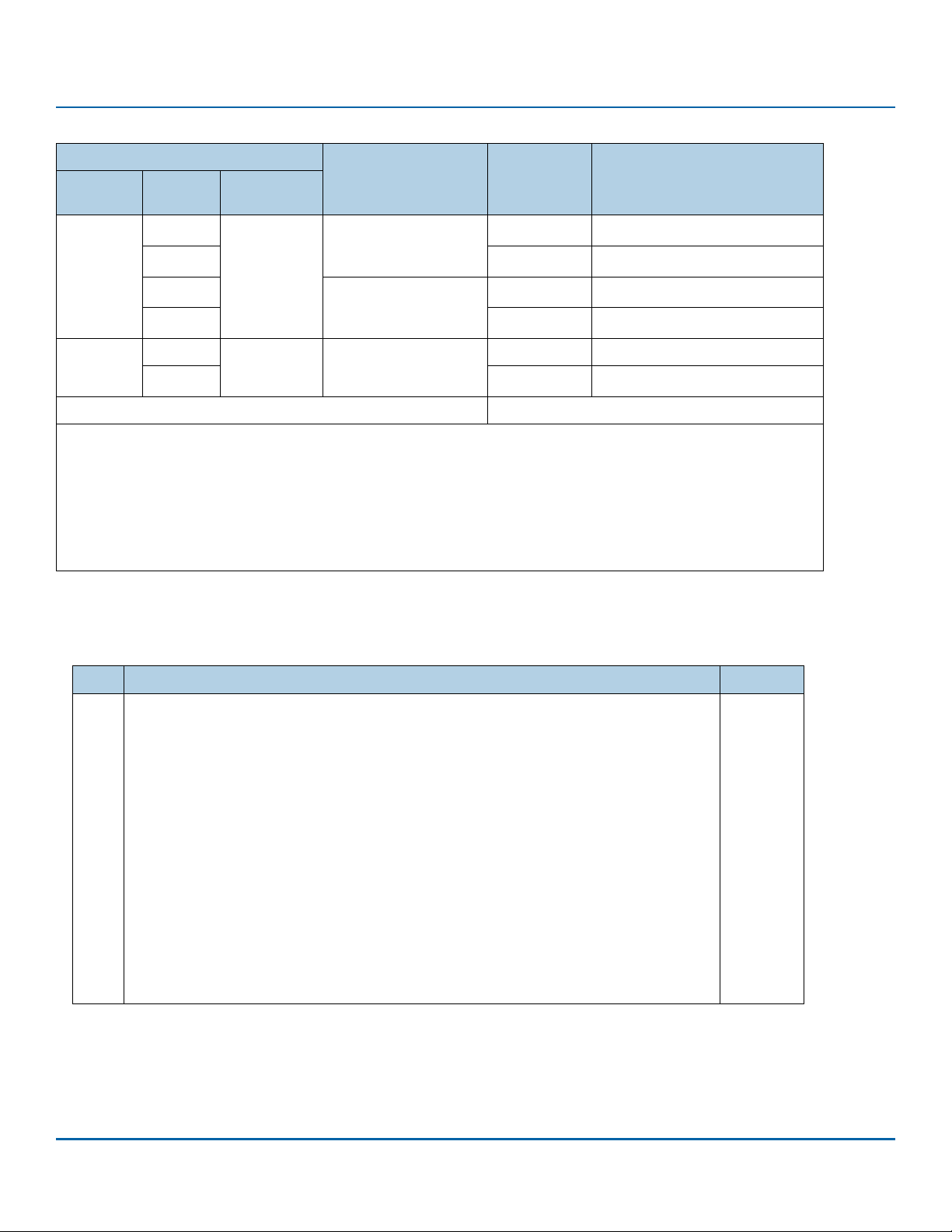
www.seagate.com Direct Access Block commands (SPC-6 and SBC-4)
Table 37 FORMAT UNIT command address descriptor usage (Sheet 2 of 2)
Field in the FORMAT UNIT CDB
FMTDATA CMPLST
0
1O
1
0
1O
0 110b
1
1O
DEFECT LIST
FORMAT
101b
(physical
sector)
(vendor
specific)
DEFECT LIST LENGTH field
in the parameter list
header
Zero
Nonzero
Vendor specific
Typ e [a]
O
O
O
Comments
[f]
See
See
See
See
[b]
[b]
[c]
[c]
and
and
and
and
All others Reserved.
[a] M = implementation is mandatory. O = implementation is optional.
[b] No DLIST is included in the parameter list.
[c] A DLIST is included in the parameter list. The device server shall add the DLIST defects to the new GLIST.
[d] The device server shall add existing GLIST defects to the new GLIST (i.e., use the existing GLIST).
[e] The device server shall not add existing GLIST defects to the new GLIST (i.e., discard the existing GLIST).
[f] All the options described in this table cause a new GLIST to be created during processing of the FORMAT UNIT
command as described in the text.
FFMT field
The fast format (FFMT) field is described in table 38.
[d]
[e]
[d]
[e]
Table 38 FFMT field description
Code Description Support
00b
The device server initializes the medium as specified in the CDB and parameter list before complet-
Mandatory
ing the format operation. After successful completion of the format operation, read commands and
verify commands are processed as described in SBC-4.
01b
The device server initializes the medium without overwriting the medium (i.e., resources for man-
Optional
aging medium access are initialized and the medium is not written) before completing the format
operation. After successful completion of the format operation, read commands and verify com
-
mands are processed as described in SBC-4.
If the device server determines that the options specified in this FORMAT UNIT command are
incompatible with the read command and verify command requirements described in SBC-4, then
the device server shall not perform the format operation and shall terminate the FORMAT UNIT
command with CHECK CONDITION status with the sense key set to ILLEGAL REQUEST and the addi
-
tional sense code set to INVALID FAST FORMAT COMBINATION.
10b
The device server initializes the medium without overwriting the medium (i.e., resources for man-
Optional
aging medium access are initialized and the medium is not written) before completing the format
operation. After successful completion of the format operation, read commands and verify com
-
mands are processed as described in SBC-4.
11b
Reserved
CONTROL byte
The CONTROL byte is defined in 2.2.7.
SCSI Commands Reference Manual, Rev. L 77
Page 78

www.seagate.com Direct Access Block commands (SPC-6 and SBC-4)
3.3.2 FORMAT UNIT parameter list
3.3.2.1 FORMAT UNIT parameter list overview
Table 39 defines the FORMAT UNIT parameter list.
Table 39 FORMAT UNIT parameter list
Bit
Byte
PARAMETER LIST HEADER field
The PARAMETER LIST HEADER is defined in 3.3.3.
INITIALIZATION PATTERN DESCRIPTOR field
The INITIALIZATION PATTERN DESCRIPTOR, if any, is defined in 3.3.4.
DEFECT LIST field
The DEFECT LIST, if any, contains address descriptors (see table 37) each specifying a location on the medium that the device server shall
exclude from the application client accessible part. This is called the DLIST.
7 6 5 4 3 2 1 0
Parameter List Header (see table 40 or table 41 in 3.3.3)
Initialization Pattern Descriptor (if any) (see table 43, in 3.3.4)
Defect List (if any)
SCSI Commands Reference Manual, Rev. L 78
Page 79
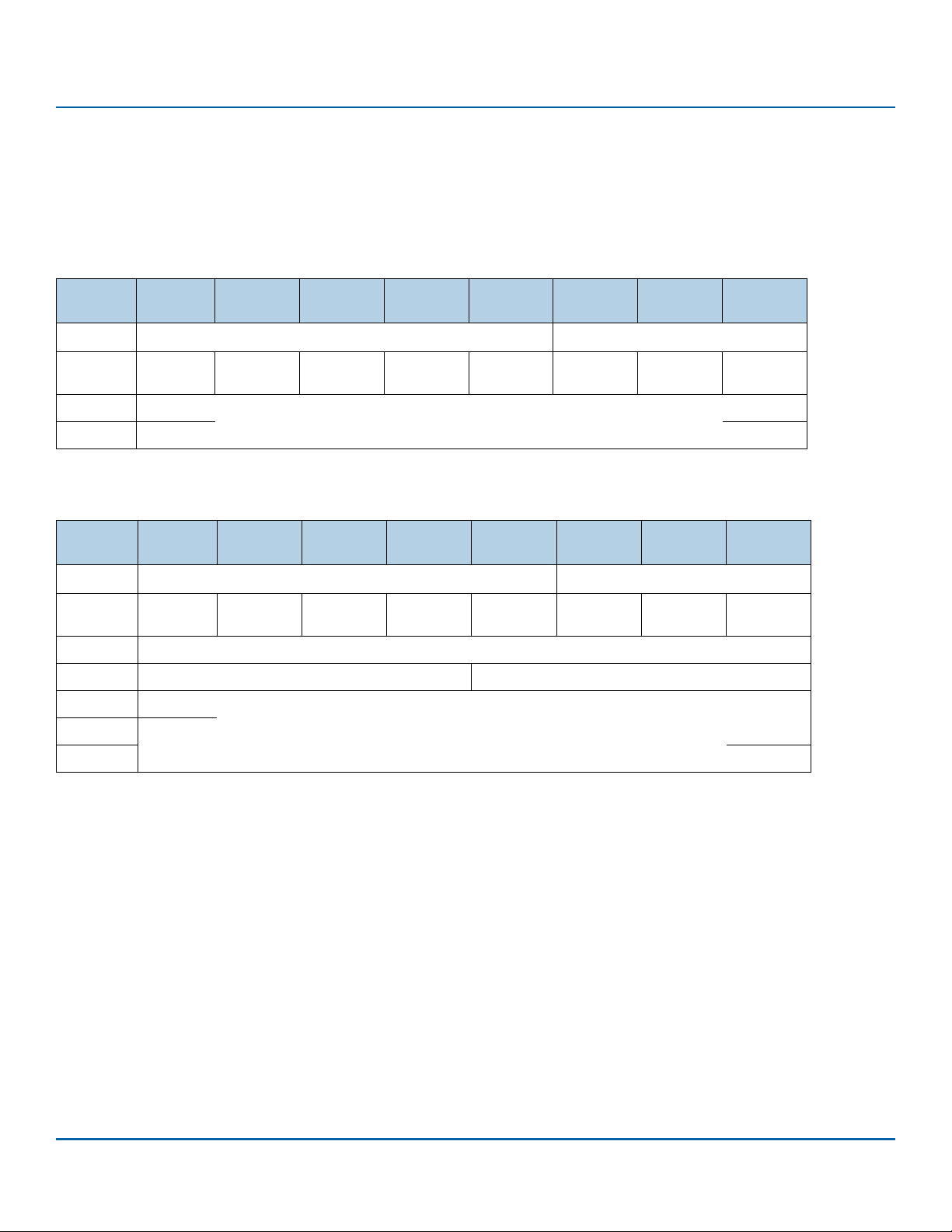
www.seagate.com Direct Access Block commands (SPC-6 and SBC-4)
3.3.3 Parameter list header
The parameter list headers (see table 40 and table 41) provide several optional format control parameters. Device servers that implement these
headers provide the application client additional control over the use of the four defect sources, and the format operation. If the application
client attempts to select any function not implemented by the device server, the device server shall terminate the command with CHECK
CONDITION status with the sense key set to ILLEGAL REQUEST and the additional sense code set to INVALID FIELD IN PARAMETER LIST.
The short parameter list header (see table 40) is used if the LONGLIST bit is set to zero in the FORMAT UNIT CDB.
Table 40 Short parameter list header
Bit
Byte
0
1
2
3
The long parameter list header (see table 41) is used if the LONGLIST bit is set to one in the FORMAT UNIT CDB.
Table 41 Long parameter list header
Bit
Byte
0
1
2
3
4
. . .
7
7 6 5 4 3 2 1 0
Reserved
FOV DPRY DCRT STPF IP Obsolete IMMED
(MSB)
DEFECT LIST LENGTH
7 6 5 4 3 2 1 0
Reserved
FOV DPRY DCRT STPF IP Obsolete IMMED
Reserved
P_I_INFORMATION PROTECTION INTERVAL EXPONENT
(MSB)
DEFECT LIST LENGTH
PROTECTION FIELDS USAGE
PROTECTION FIELDS USAGE
Vendor
specific
(LSB)
Vendor
specific
(LSB)
The PROTECTION FIELD USAGE field in combination with the FMTPINFO field (see table 42) specifies the requested protection type (see SBC-4).
SCSI Commands Reference Manual, Rev. L 79
Page 80

www.seagate.com Direct Access Block commands (SPC-6 and SBC-4)
Table 42 FMTPINFO field and PROTECTION FIELDS USAGE field (Sheet 1 of 2)
Device server
indication
[a]
SPT
PROTECT
Application client
specification
FMTP
[b]
INFO
PROTECTION
FIELD USAGE
xxxb 0 00b 000b
xxxb 0 00b >000b
xxxb 0 01b xxxb
xxxb 0 1xb xxxb
xxxb 1 00b 000b
xxxb 1 00b >000b
xxxb 1 0b xxxb
000b
001b
011b
1
10b 000b
111b
000b
001b
011b
1
10b >000b
111b
000b 1
11b xxxb
Description
The logical unit shall be formatted to type 0 protection
P_TYPE field
Illegal
Illegal
Illegal
The logical unit shall be formatted to type 0 protection
P_TYPE field
Illegal
Illegal
The logical unit shall be formatted to type 1 protection
P_TYPE field
Illegal
Illegal
[e]
[f]
[f]
[e]
[f]
[e]
[f]
[d]
being set to 000b.
[d]
being set to 000b.
[d]
being set to 000b.
[c]
(see SBC-4) resulting in the
[c]
(see SBC-4) resulting in the
[g]
(see SBC-4) resulting in the
000b
001b
011b
1
11b 000b
111b
001b
010b
011b
100b
1
1
11b >000b
11b 000b
011b
100b
101b
1
11b 001b
111b
011b
100b
101b
1 11b >001b
111b
110b 1 1xb xxxb
The logical unit shall be formatted to type 2 protection
P_TYPE field
Illegal
Illegal
The logical unit shall be formatted to type 3 protection.
P_TYPE field
Illegal
[e]
[e]
[e]
[d]
being set to 001b.
[d]
being set to 010b.
Reserved
[g]
(see SBC-4) resulting in the
[g]
(see SBC-4) resulting in the
SCSI Commands Reference Manual, Rev. L 80
Page 81

www.seagate.com Direct Access Block commands (SPC-6 and SBC-4)
Table 42 FMTPINFO field and PROTECTION FIELDS USAGE field (Sheet 2 of 2)
Device server
indication
Application client
specification
Description
[a]
SPT
[a] See the Extended INQUIRY Data VPD page (see 5.4.10) for the definition of the SPT field.
[b] See the standard INQUIRY data (see 3.8.2) for the definition of the PROTECT bit.
[c] The device server shall format the medium to the block length specified in the mode parameter block descriptor of the mode parameter header (see
[d] See the READ CAPACITY command (see 3.24.1) for the definition of the P_TYPE field.
[e] The device server shall terminate the command with CHECK CONDITION status with the sense key set to ILLEGAL REQUEST and the additional sense
[f] The device server shall terminate the command with CHECK CONDITION status with the sense key set to ILLEGAL REQUEST and the additional sense
[g] The device server shall format the medium to the block length specified in the mode parameter block descriptor of the mode parameter header plus
PROTECT
5.3.3).
code set to INVALID FIELD IN PARAMETER LIST.
code set to INVALID FIELD IN CDB.
eight (e.g., if the block length is 512, then the formatted block length is 520). Following a successful format, the PROT_EN bit in the READ CAPACITY (16)
parameter data (see 3.25.2) indicates whether protection information (see SBC-4) is enabled.
[b]
FMTP
INFO
PROTECTION
FIELD USAGE
FOV (Format Options Valid) bit
0 A format options valid (FOV) bit set to zero specifies that the device server shall use its default settings for the DPRY, DCRT, STPF, and IP
bits. If the FOV bit is set to zero, the application client shall set these bits to zero. If the FOV bit is set to zero and any of the other bits
listed in this paragraph are not set to zero, the device server shall terminate the command with CHECK CONDITION status with the sense
key set to ILLEGAL REQUEST and the additional sense code set to INVALID FIELD IN PARAMETER LIST.
1 A FOV bit set to one specifies that the device server shall examine the values of the DPRY, DCRT, STPF, and IP bits. When the FOV bit is set
to one, the DPRY, DCRT, STPF, and IP bits are defined as follows.
DPRY (Disable Primary) bit
0 A disable primary (DPRY) bit set to zero specifies that the device server shall not use parts of the medium identified as defective in the
PLIST for application client accessible logical blocks. If the device server is not able to locate the PLIST or it is not able to determine
whether a PLIST exists, it shall take the action specified by the STPF bit.
1 A DPRY bit set to one specifies that the device server shall not use the PLIST to identify defective areas of the MEDIUM. The PLIST shall
not be deleted.
DCRT (disable certification) bit
0 A disable certification (DCRT) bit set to zero specifies that the device server shall perform a vendor-specific medium certification opera-
tion to generate a CLIST.
1 A DCRT bit set to one specifies that the device server shall not perform any vendor-specific medium certification process or format veri-
fication operation.
STPF (Stop Format) bit
The stop format (STPF) bit controls the behavior of the device server if one of the following events occurs:
a) The device server has been requested to use the PLIST (i.e., the DPRY bit is set to zero) or the GLIST (i.e., the CMPLST bit is set to zero)
and the device server is not able to locate the list or determine whether the list exists; or
b) The device server has been requested to use the PLIST (i.e., the DPRY bit is set to zero) or the GLIST (i.e., the CMPLST bit is set to zero),
and the device server encounters an error while accessing the defect list.
0 A STPF bit set to zero specifies that, if one or both of these events occurs, the device server shall continue to process the FORMAT UNIT
command. The device server shall return CHECK CONDITION status at the completion of the FORMAT UNIT command with the sense key
set to RECOVERED ERROR and the additional sense code set to either DEFECT LIST NOT FOUND if the condition described in item a)
occurred, or DEFECT LIST ERROR if the condition described in item b) occurred.
1 A STPF bit set to one specifies that, if one or both of these events occurs, the device server shall terminate the FORMAT UNIT command
with CHECK CONDITION status and the sense key shall be set to MEDIUM ERROR with the additional sense code set to either DEFECT
LIST NOT FOUND if the condition described in item a) occurred, or DEFECT LIST ERROR if the condition described in item b) occurred.
SCSI Commands Reference Manual, Rev. L 81
Page 82

www.seagate.com Direct Access Block commands (SPC-6 and SBC-4)
NOTE The use of the FMTDATA bit, the CMPLST bit, and the parameter list header allow the application client
to control the source of the defect lists used by the FORMAT UNIT command. Setting the DEFECT LIST
LENGTH field to zero allows the application client to control the use of PLIST and CLIST without having
to specify a DLIST.
IP (initialization pattern) bit
0 An initialization pattern (IP) bit set to zero specifies that an initialization pattern descriptor is not included and that the device server
shall use its default initialization pattern.
1 An IP bit set to one specifies that an initialization pattern descriptor (see 3.3.4) is included in the FORMAT UNIT parameter list following
the parameter list header.
IMMED (Immediate) bit
0 An immediate (IMMED) bit set to zero specifies that the device server shall return status after the format operation has completed.
1 An IMMED bit value set to one specifies that the device server shall return status after the entire parameter list has been transferred.
P_I_INFORMATION field
The P_I_INFORMATION field shall be set to zero.
PROTECTION INTERVAL EXPONENT field
For a type 1 protection information request, if the PROTECTION INTERVAL EXPONENT field is not set to zero, then the device server shall
terminate the command with CHECK CONDITION status with the sense key set to ILLEGAL REQUEST and the additional sense code set to
INVALID FIELD IN PARAMETER LIST.
For a type 2 protection or a type 3 protection format request, the protection interval exponent determines the length of user data to be sent
before protection information is transferred (i.e., the protection information interval).
The protection information interval is calculated as follows:
Equation 1 protection information interval = logical block length / 2
where:
logical block length is the length in bytes of a logical block as specified in the mode parameter block descriptor (see
5.3.4.1)
protection interval exponent is the contents of the PROTECTION INTERVAL EXPONENT field
If the protection information interval calculates to a value that is not an even number (e.g., 520/2
32.5 and 520/2
ILLEGAL REQUEST and the additional sense code set to INVALID FIELD IN PARAMETER LIST.
10
= 0.508), then the device server shall terminate the command with CHECK CONDITION status with the sense key set to
(protection interval exponent)
3
= 65) or not a whole number (e.g., 520/24 =
DEFECT LIST LENGTH field
The DEFECT LIST LENGTH field specifies the total length in bytes of the defect list (i.e., the address descriptors) that follows and does not
include the initialization pattern descriptor, if any. The formats for the address descriptor(s) are shown in table 45.
Address descriptors should be in ascending order. More than one physical or logical block may be affected by each address descriptor. If the
address descriptors are not in the required order, the device server shall terminate the command with CHECK CONDITION status with the sense
key set to ILLEGAL REQUEST and the additional sense code set to INVALID FIELD IN PARAMETER LIST.
SCSI Commands Reference Manual, Rev. L 82
Page 83

www.seagate.com Direct Access Block commands (SPC-6 and SBC-4)
3.3.4 Initialization pattern descriptor
The initialization pattern descriptor specifies that the device server initialize logical blocks to a specified pattern. The initialization pattern
descriptor (see table 43) is sent to the device server as part of the FORMAT UNIT parameter list.
Table 43 Initialization pattern descriptor
Bit
Byte
0
1
2
3
4
. . .
n
SI (Security Initialize) bit
This bit is not supported on Seagate products. Customers should use the SANITIZE command to satisfy secure initialization requirements.
INITIALIZATION PATTERN TYPE field
The INITIALIZATION PATTERN TYPE field (see table 44) specifies the type of pattern the device server shall use to initialize each logical block
within the application client accessible part of the medium. All bytes within a logical block shall be written with the initialization pattern. The
initialization pattern is modified by the IP MODIFIER field as described in table 44.
Tab le 4 4 INITIALIZATION PATTERN TYPE field
Code Description
00h
01h
02h - 7Fh
80h - FFh
[a] If the INITIALIZATION PATTERN LENGTH field is not set to zero, the device server shall terminate the command with CHECK CONDI-
TION status with the sense key set to ILLEGAL REQUEST and the additional sense code set to INVALID FIELD IN PARAMETER LIST.
[b] If the INITIALIZATION PATTERN LENGTH field is set to zero, the device server shall terminate the command with CHECK CONDITION
status with the sense key set to ILLEGAL REQUEST and the additional sense code set to INVALID FIELD IN PARAMETER LIST.
7 6 5 4 3 2 1 0
OBSOLETE SI Reserved
INITIALIZATION PATTERN TYPE
(MSB)
INITIALIZATION PATTERN LENGTH (n - 3)
(LSB)
INITIALIZATION PATTERN
Use a default initialization pattern [a]
Repeat the pattern specified in the INITIALIZATION PATTERN field as required to fill the logical block [b]
Reserved
Vendor-specific
INITIALIZATION PATTERN LENGTH field
The INITIALIZATION PATTERN LENGTH field specifies the number of bytes contained in the INITIALIZATION PATTERN field. If the initialization
pattern length exceeds the current block length the device server shall terminate the command with CHECK CONDITION status with the sense
key set to ILLEGAL REQUEST and the additional sense code set to INVALID FIELD IN PARAMETER LIST.
INITIALIZATION PATTERN field
The INITIALIZATION PATTERN field specifies the initialization pattern.
SCSI Commands Reference Manual, Rev. L 83
Page 84
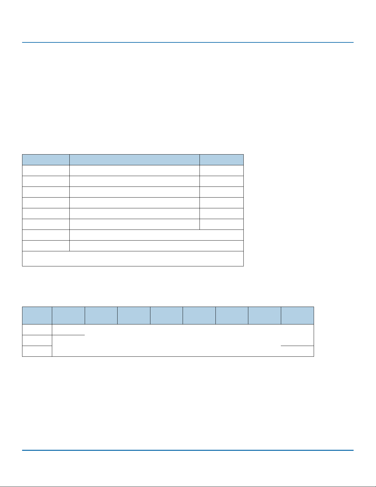
www.seagate.com Direct Access Block commands (SPC-6 and SBC-4)
3.3.5 Address descriptor formats
3.3.5.1 Address descriptor formats overview
This subclause describes the address descriptor formats used in the FORMAT UNIT command, the READ DEFECT DATA commands (see 3.26 and
3.27), and the Translate Address diagnostic pages (see 5.1.3) of the SEND DIAGNOSTIC command and the RECEIVE DIAGNOSTIC RESULTS
command.
The format type of an address descriptor is specified with:
a) the DEFECT LIST FORMAT field in the CDB, for the FORMAT UNIT command and the READ DEFECT DATA commands;
b) the SUPPLIED FORMAT field, for the SEND DIAGNOSTIC command Translate Address diagnostic page; or
c) the TRANSLATE FORMAT field, for the RECEIVE DIAGNOSTIC RESULTS command Translate Address diagnostic page.
Table 45 defines the types of address descriptors.
Table 45 Address descriptor formats
Format type Description Reference
000b
001b
010b
011b
100b
101b
110b
All others
[a] This address descriptor format type is defined for direct access block devices
using rotating media (see SBC-4).
Short block format address descriptor 3.3.5.2
Extended bytes from index address descriptor
Extended physical sector address descriptor
Long block format address descriptor 3.3.5.5
Bytes from index format address descriptor 3.3.5.6
Physical sector format address descriptor 3.3.5.7
Vendor-specific
Reserved
[a]
[a]
3.3.5.3
3.3.5.4
3.3.5.2 Short block format address descriptor
A format type of 000b specifies the short block format address descriptor defined in table 46.
Table 46 Short block format address descriptor (000b)
Bit
Byte
0
. . .
3
7 6 5 4 3 2 1 0
(MSB)
SHORT BLOCK ADDRESS
(LSB)
SHORT BLOCK ADDRESS field
For the FORMAT UNIT command, the SHORT BLOCK ADDRESS field contains the four-byte LBA of a defect. For the READ DEFECT DATA commands, the SHORT BLOCK ADDRESS field contains a vendor-specific four-byte value. For the Translate Address diagnostic pages, the SHORT
BLOCK ADDRESS field contains a four-byte LBA or a vendor-specific four byte value that is greater than the capacity of the medium.
SCSI Commands Reference Manual, Rev. L 84
Page 85

www.seagate.com Direct Access Block commands (SPC-6 and SBC-4)
3.3.5.3 Extended bytes from index address descriptor
A format type of 001b specifies the extended bytes from index address descriptor defined in table 47. For the FORMAT UNIT command and the
READ DEFECT DATA command, this descriptor specifies the location of a defect that is either:
a) the length of one track;
b) is less than the length of a physical block; or
c) a defect that starts from one address descriptor and extends to the next address descriptor.
For the Translate Address diagnostic pages, this descriptor specifies the location of an LBA. If format type 001b is used in the SUPPLIED FORMAT
field of a Translate Address Output diagnostic page (see 5.1.4), and the MADS bit in the ADDRESS TO TRANSLATE field is set to one, then the
device server shall terminate the SEND DIAGNOSTIC command with CHECK CONDITION status with the sense key set to ILLEGAL REQUEST and
the additional sense code set to INVALID FIELD IN PARAMETER LIST.
Table 47 Bytes from index format address descriptor (100b)
Bit
Byte
0
. . .
2
3
4
. . .
7
CYLINDER NUMBER field
The CYLINDER NUMBER field contains the cylinder number.
HEAD NUMBER field
The HEAD NUMBER field contains the head number.
MADS bit
A multi-address descriptor start (MADS) bit set to one specifies that this descriptor defines the beginning of a defect that spans multiple
address descriptors. The defect may be a number of sequential physical blocks on the same cylinder and head (i.e., a track) or may be a number
of sequential tracks on the same head. A MADS bit set to zero specifies that:
a) this descriptor defines the end of a defect if the previous address descriptor has the MADS bit set to one; or
b) this descriptor defines a single defective physical track (i.e., the BYTES FROM INDEX field contains FFF_FFFFh) or a single defective physical
block (i.e., the BYTES FROM INDEX field does not contain FFF_FFFFh).
See SBC-4 for valid combinations of two address descriptors that describe a defect.
7 6 5 4 3 2 1 0
(MSB)
CYLINDER NUMBER
(LSB)
HEAD NUMBER
MADS Reserved (MSB)
BYTES FROM INDEX
(LSB)
BYTES FROM INDEX field
a) if not set to FFF_FFFFh, contains the number of bytes from the index (e.g., from the start of the track) to the location being described; or
b) if set to FFF_FFFFh, specifies that the entire track is being described.
For sorting bytes from index format address descriptors, the cylinder number is the most significant part of the address and the bytes from
index is the least significant part of the address. More than one logical block may be described by this descriptor.
SCSI Commands Reference Manual, Rev. L 85
Page 86

www.seagate.com Direct Access Block commands (SPC-6 and SBC-4)
3.3.5.4 Extended physical sector address descriptor
A format type of 010b specifies the extended physical sector address descriptor defined in table 48. For the FORMAT UNIT command and the
READ DEFECT DATA command, this descriptor specifies the location of a defect that is either:
a) the length of one track;
b) is less than the length of a physical block; or
c) a defect that starts from one address descriptor and extends to the next address descriptor.
For the Translate Address diagnostic pages, this descriptor specifies the location of an LBA. If format type 010b is used in the SUPPLIED FORMAT
field of a Translate Address Output diagnostic page (see 5.1.4), and the MADS bit in the ADDRESS TO TRANSLATE field is set to one, then the
device server shall terminate the SEND DIAGNOSTIC command with CHECK CONDITION status with the sense key set to ILLEGAL REQUEST and
the additional sense code set to INVALID FIELD IN PARAMETER LIST.
Table 48 Bytes from index format address descriptor (100b)
Bit
Byte
0
. . .
2
3
4
. . .
7
CYLINDER NUMBER field
The CYLINDER NUMBER field contains the cylinder number.
HEAD NUMBER field
The HEAD NUMBER field contains the head number.
MADS bit
A multi-address descriptor start (MADS) bit set to one specifies that this descriptor defines the beginning of a defect that spans multiple
address descriptors. The defect may be a number of sequential physical blocks on the same cylinder and head (i.e., a track) or may be a number
of sequential tracks on the same head. A MADS bit set to zero specifies that:
a) this descriptor defines the end of a defect if the previous address descriptor has the MADS bit set to one; or
b) this descriptor defines a single defective physical track (i.e., the BYTES FROM INDEX field contains FFF_FFFFh) or a single defective physical
block (i.e., the BYTES FROM INDEX field does not contain FFF_FFFFh).
See SBC-4 for valid combinations of two address descriptors that describe a defect.
The SECTOR NUMBER field contains the sector number. A SECTOR NUMBER field set to FFF_FFFFh specifies that the entire track is being
described.
7 6 5 4 3 2 1 0
(MSB)
CYLINDER NUMBER
(LSB)
HEAD NUMBER
MADS Reserved (MSB)
SECTOR NUMBER
(LSB)
SECTOR NUMBER field
a) if not set to FFF_FFFFh, contains the sector number of the location being described; or
b) if set to FFF_FFFFh, specifies that the entire track is being described.
For sorting extended physical sector address descriptors, the cylinder number is the most significant part of the address and the sector number
is the least significant part of the address. More than one logical block may be described by this descriptor.
SCSI Commands Reference Manual, Rev. L 86
Page 87
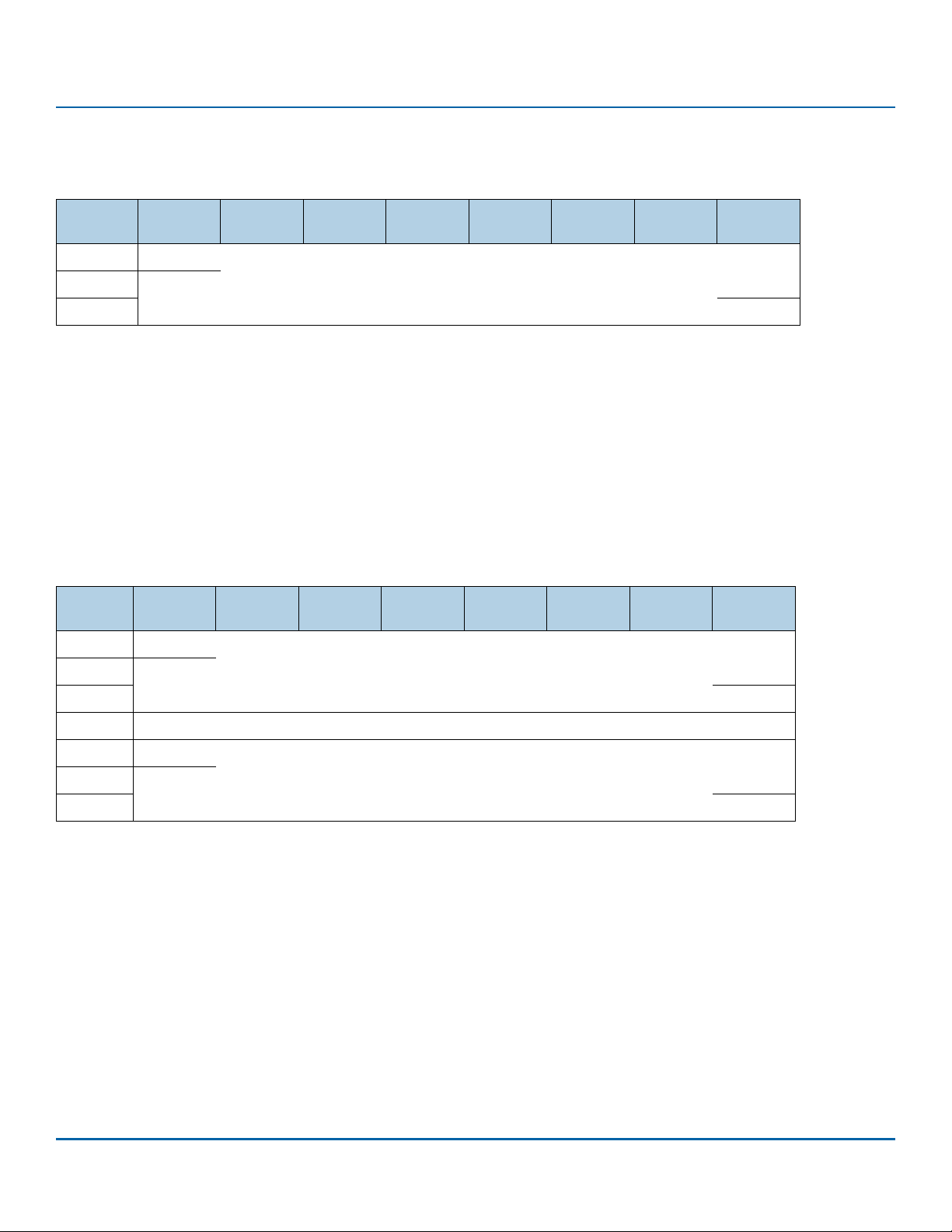
www.seagate.com Direct Access Block commands (SPC-6 and SBC-4)
3.3.5.5 Long block format address descriptor
A format type of 011b specifies the long block format address descriptor defined in table 49.
Table 49 Long block format address descriptor (011b)
Bit
Byte
0
. . .
7
LONG BLOCK ADDRESS field
For the FORMAT UNIT command, the LONG BLOCK ADDRESS field contains the eight-byte logical block address of a defect. If multiple logical
blocks are contained within a physical block, then the device server may consider logical blocks in addition to the one specified by this descrip
tor as containing defects. For the READ DEFECT DATA commands, the LONG BLOCK ADDRESS field contains a vendor-specific eight-byte value.
For the Translate Address diagnostic pages, the LONG BLOCK ADDRESS field contains a four-byte LBA or a vendor-specific four byte value that
is greater than the capacity of the medium.
7 6 5 4 3 2 1 0
(MSB)
LONG BLOCK ADDRESS
(LSB)
3.3.5.6 Bytes from index format address descriptor
A format type of 100b specifies the bytes from index address descriptor defined in table 50. For the FORMAT UNIT command and the READ
DEFECT DATA commands, this descriptor specifies the location of a defect that is either the length of one track or is no more than eight bytes
long. For the Translate Address diagnostic pages, this descriptor specifies the location of a track or the first byte or last byte of an area.
Table 50 Bytes from index format address descriptor (100b)
Bit
Byte
0
. . .
2
3
4
. . .
7
7 6 5 4 3 2 1 0
(MSB)
CYLINDER NUMBER
(LSB)
HEAD NUMBER
(MSB)
BYTES FROM INDEX
(LSB)
-
CYLINDER NUMBER field
The CYLINDER NUMBER field contains the cylinder number.
HEAD NUMBER field
The HEAD NUMBER field contains the head number.
BYTES FROM INDEX field
The BYTES FROM INDEX field contains the number of bytes from the index (e.g., from the start of the track) to the location being described. A
BYTES FROM INDEX field set to FFFFFFFFh specifies that the entire track is being described.
For sorting bytes from index format address descriptors, the cylinder number is the most significant part of the address and the bytes from
index is the least significant part of the address. More than one logical block may be described by this descriptor.
SCSI Commands Reference Manual, Rev. L 87
Page 88
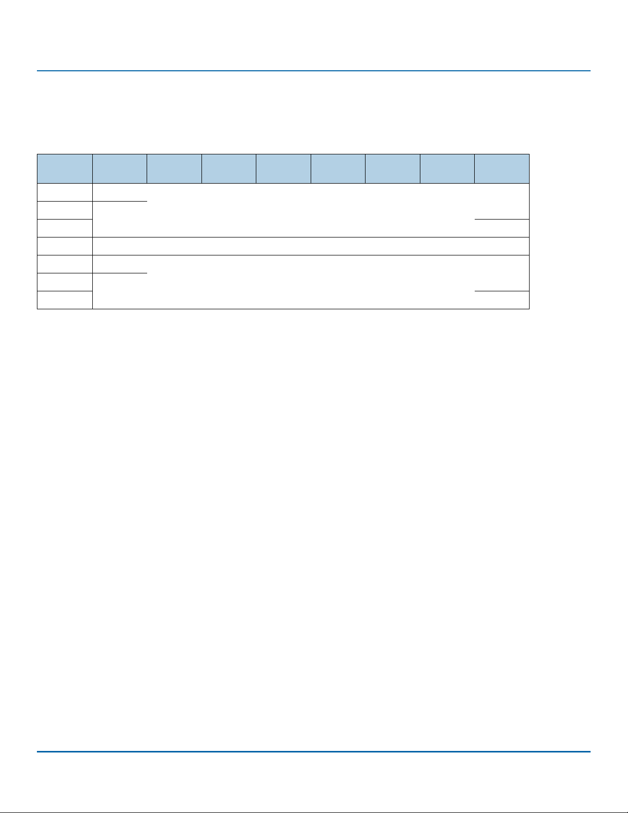
www.seagate.com Direct Access Block commands (SPC-6 and SBC-4)
3.3.5.7 Physical sector format address descriptor
A format type of 101b specifies the physical sector address descriptor defined in table 51. For the FORMAT UNIT command and the READ DEFECT
DATA commands, this descriptor specifies the location of a defect that is either the length of one track or the length of one sector. For the
Translate Address diagnostic pages, this descriptor specifies the location of a track or a sector.
Table 51 Physical sector format address descriptor (101b)
Bit
Byte
0
. . .
2
3
4
. . .
7
CYLINDER NUMBER field
The CYLINDER NUMBER field contains the cylinder number.
HEAD NUMBER field
The HEAD NUMBER field contains the head number.
SECTOR NUMBER field
The SECTOR NUMBER field contains the sector number. A SECTOR NUMBER field set to FFFFFFFFh specifies that the entire track is being
described.
For sorting physical sector format address descriptors, the cylinder number is the most significant part of the address and the sector number is
the least significant part of the address. More than one logical block may be described by this descriptor.
7 6 5 4 3 2 1 0
(MSB)
CYLINDER NUMBER
(LSB)
HEAD NUMBER
(MSB)
SECTOR NUMBER
(LSB)
SCSI Commands Reference Manual, Rev. L 88
Page 89
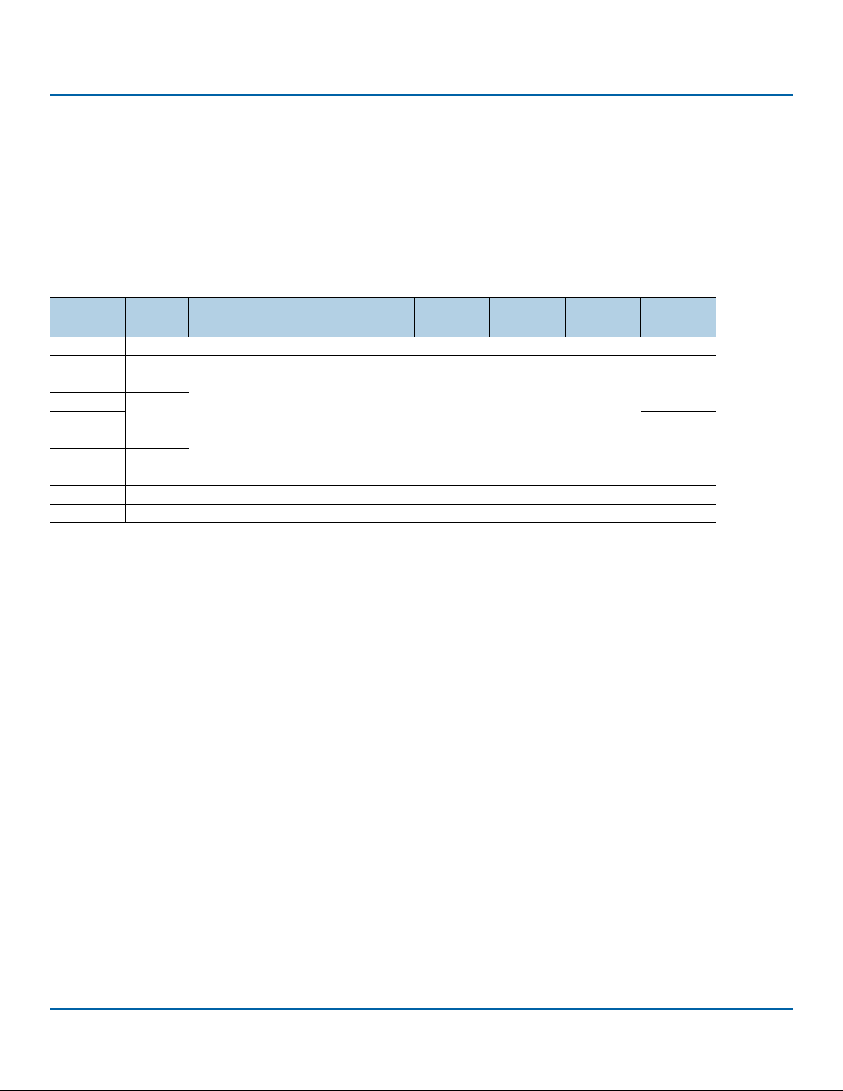
www.seagate.com Direct Access Block commands (SPC-6 and SBC-4)
3.4 GET LBA STATUS (16) command
3.4.1 GET LBA STATUS (16) command overview
The GET LBA STATUS (16) command (see table 52) requests that the device server transfer parameter data describing the logical block
provisioning status (see SBC-4) for the specified LBA and zero or more subsequent LBAs to the Data-In Buffer.
The device server may or may not process this command as an uninterrupted sequence of actions (e.g., if concurrent operations are occurring
that affect the logical block provisioning status, then the returned parameter data may be inconsistent or out of date).
This command uses the SERVICE ACTION IN (16) CDB format (see SBC-4 - Annex A.2).
Table 52 GET LBA STATUS command
Bit
Byte
0 OPERATION CODE (9Eh)
1 Reserved SERVICE ACTION (12h)
2 (MSB)
9 (LSB)
10 (MSB)
13 (LSB)
14 REPORT TYPE
15 CONTROL
OPERATION CODE field
The OPERATION CODE field is defined in SPC-6 and shall be set to the value shown in table 52 for the GET LBA STATUS (16) command.
SERVICE ACTION field
The SERVICE ACTION field is defined in 2.2.2 and shall be set to the value shown in table 52 for the GET LBA STATUS (16) command.
STARTING LOGICAL BLOCK ADDRESS field
The STARTING LOGICAL BLOCK ADDRESS field specifies the LBA of the first logical block addressed by this command. If the specified starting
LBA exceeds the capacity of the medium (see SPC-6), then the device server shall terminate the command with CHECK CONDITION status with
the sense key set to ILLEGAL REQUEST and the additional sense code set to LOGICAL BLOCK ADDRESS OUT OF RANGE.
7 6 5 4 3 2 1 0
STARTING LOGICAL BLOCK ADDRESS. . .
ALLOCATION LENGTH. . .
ALLOCATION LENGTH field
The ALLOCATION LENGTH field is defined in 2.2.6. In response to a GET LBA STATUS command, the device server may send less data to the
Data-In Buffer than is specified by the allocation length. If, in response to a single GET LBA STATUS command, the device server does not send
sufficient data to the Data-In Buffer to satisfy the requirement of the application client, then, to retrieve additional information, the application
client may send additional GET LBA STATUS commands with different starting LBA values.
SCSI Commands Reference Manual, Rev. L 89
Page 90
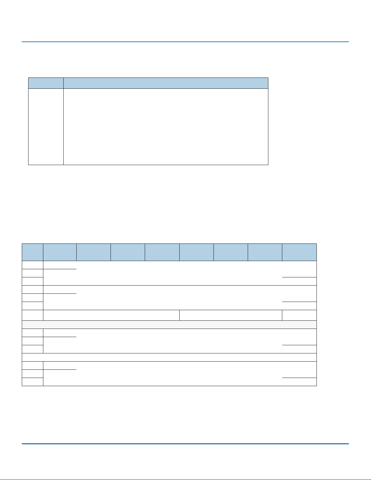
www.seagate.com Direct Access Block commands (SPC-6 and SBC-4)
REPORT TYPE field
The REPORT TYPE field specifies the type of LBA status descriptors to return as shown in (see table 53).
Table 53 REPORT TYPE field
Code Description
0h
1h
2h
3h
4h
10h
All others
CONTROL byte
The CONTROL byte is defined in 2.2.7.
Return descriptors for all LBAs
Return descriptors for all LBAs using only non-zero provisioning status (see 3.4.2.2)
Return descriptors for all LBAs that are mapped (see SBC-4)
Return descriptors for all LBAs that are deallocated (see SBC-4)
Return descriptors for all LBAs that are anchored (see SBC-4)
Return descriptors for LBAs that may return an unrecovered error
Reserved
3.4.2 GET LBA STATUS parameter data
3.4.2.1 GET LBA STATUS parameter data overview
The GET LBA STATUS parameter data (see table 54) contains an eight-byte header followed by one or more LBA status descriptors.
Table 54 GET LBA STATUS parameter data
Bit
Byte
0 (MSB)
3 (LSB)
4
6
7
8
23
n-15
n
7 6 5 4 3 2 1 0
PARAMETER DATA LENGTH (n-3). . .
Reserved. . .
Reserved
COMPLETION CONDITION
LBA status descriptors
LBA status descriptor [first] (see 3.4.2.2). . .
. . .
LBA status descriptor [last] (see 3.4.2.2) (if any). . .
RTP
SCSI Commands Reference Manual, Rev. L 90
Page 91

www.seagate.com Direct Access Block commands (SPC-6 and SBC-4)
PARAMETER DATA LENGTH field
The PARAMETER DATA LENGTH field indicates the number of bytes of parameter data that follow. The value in the PARAMETER DATA LENGTH
field shall be:
a) set to 4, if there are no status descriptors to report;
b) at least 20 (i.e., the available parameter data shall contain at least one LBA status descriptor); and
c) four added to a multiple of 16 (i.e., the available parameter data shall end on a boundary between LBA Status descriptors).
As a result of processing considerations not defined by this standard, two GET LBA STATUS commands with identical values in all CDB fields
may result in two different values in the PARAMETER DATA LENGTH field
The relationship between the PARAMETER DATA LENGTH field and the ALLOCATION LENGTH field in the CDB is defined in 2.2.6.
COMPLETION CONDITION field
The COMPLETION CONDITION field indicates the condition that caused completion of the GET LBA STATUS command. The COMPLETION CONDITION field is described in table 55.
Table 55 COMPLETION CONDITION field
Code Description
000b
001b
010b
011b
All others
No indication of the completion condition.
The command completed as a result of meeting the allocation length.
a
The command completed as a result of completing the scan length.
The command completed as a result of reaching the capacity of the medium (see SBC-4).
Reserved
a This only applies to the GET LBA STATUS (32) command
If the command completes by reaching the capacity of the medium and any other condition at the same time, then the COMPLETION CONDITION field shall be set to 011b.
Report Type Processed (RTP) bit
The report type processed (RTP) bit indicates whether the value in the REPORT TYPE field was processed. If the RTP bit is set to zero, then the
REPORT TYPE field was not processed (i.e., the GET LBA STATUS parameter data is returned as if the REPORT TYPE field was set to 00h). If the RTP
bit is set to one, then the REPORT TYPE field was processed. If a device server supports the REPORT TYPE field set to a non-zero value, then the
RTP bit shall be set to one.
SCSI Commands Reference Manual, Rev. L 91
Page 92
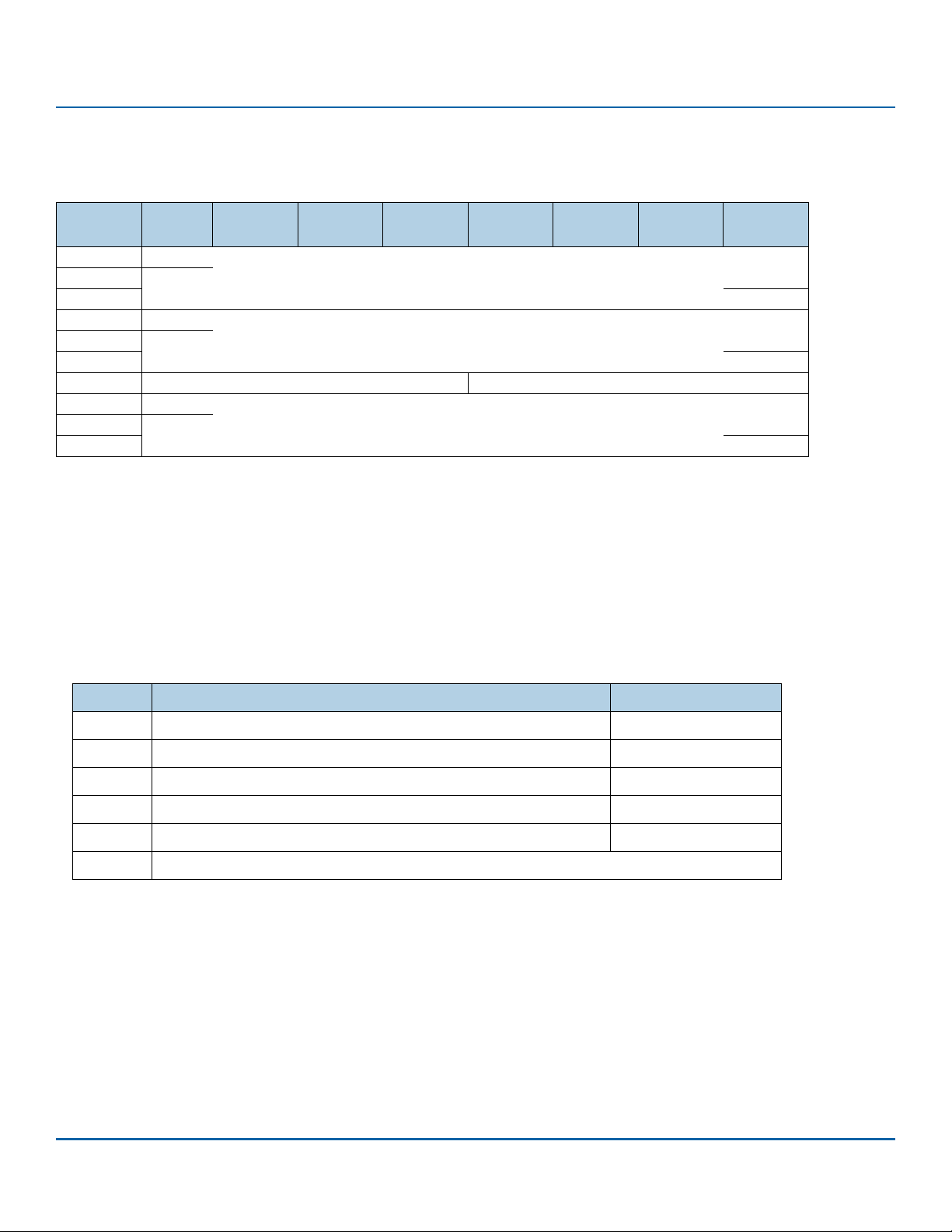
www.seagate.com Direct Access Block commands (SPC-6 and SBC-4)
3.4.2.2 LBA status descriptor
The LBA status descriptor (see table 56) contains LBA status information for one or more LBAs.
Tab le 5 6 LB A status descriptor format
Bit
Byte
0 (MSB)
7 (LSB)
8 (MSB)
11 (LSB)
12 Reserved PROVISIONING STATUS
13
15
LBA STATUS LOGICAL BLOCK ADDRESS field
The LBA STATUS LOGICAL BLOCK ADDRESS field contains the first LBA of the LBA extent for which this descriptor reports LBA status.
NUMBER OF LOGICAL BLOCKS field
The NUMBER OF LOGICAL BLOCKS field contains the number of logical blocks in that LBA extent. The device server should return the largest
possible value in the NUMBER OF LOGICAL BLOCKS field.
PROVISIONING STATUS field
The PROVISIONING STATUS field is defined in table 57.
Table 57 PROVISIONING STATUS field
7 6 5 4 3 2 1 0
LBA STATUS LOGICAL BLOCK ADDRESS. . .
NUMBER OFLOGICAL BLOCKS. . .
Reserved. . .
Code Description Allowed for report types
0h
1h
2h
3h
4h
All others
If the logical unit is fully provisioned (see SBC-4), then the PROVISIONING STATUS field for all LBAs shall be set to:
a) 0h (i.e., mapped or unknown), if the RTP bit is set to zero;
b) 0h (i.e., mapped or unknown), if the REPORT TYPE field is set to 00h in the CDB and the RTP bit is set to one; or
c) 3h (i.e., mapped), if the REPORT TYPE field is not set to 00h in the CDB and the RTP bit is set to one.
Each LBA in the LBA extent is mapped (see SBC-4) or has an unknown state. 00h
Each LBA in the LBA extent is deallocated (see SBC-4). 00h, 01h, 03h, 10h
Each LBA in the LBA extent is anchored (see SBC-4). 00h, 01h, 04h, 10h
Each LBA in the LBA extent is mapped. 01h, 02h, 10h
Each LBA in the LBA extent has an unknown provisioning status. 01h, 10h
Reserved
SCSI Commands Reference Manual, Rev. L 92
Page 93

www.seagate.com Direct Access Block commands (SPC-6 and SBC-4)
ADDITIONAL STATUS field
The ADDITIONAL STATUS field shall be set to 00h if the REPORT TYPE field is set to 00h in the CDB and shall be as shown in table 58 for all other
values of report type.
Table 58 ADDITIONAL STATUS field
Code Description
00h
01h
All others
No additional status to report.
The device server has detected that each LBA in the LBA extent may return an unrecovered error.
Reserved
3.4.2.3 LBA status descriptor relationships
The LBA STATUS LOGICAL BLOCK ADDRESS field in the first LBA status descriptor returned in the GET LBA STATUS parameter data shall contain
the lowest numbered LBA that is greater than or equal to the starting logical block address specified in the CDB that meets the requirements
for the specified report type. For subsequent LBA status descriptors, the contents of the LBA STATUS LOGICAL BLOCK ADDRESS field shall contain:
a) for a non-zero report type, the value of the lowest numbered LBA meeting the requirements for the specified report type that is greater
than or equal to the sum of the values in:
A) the LBA STATUS LOGICAL BLOCK ADDRESS field in the previous LBA status descriptor;
and
B) the NUMBER OF LOGICAL BLOCKS field in the previous LBA status descriptor;
or
b) for report type 0h, the sum of the values in:
A) the LBA STATUS LOGICAL BLOCK ADDRESS field in the previous LBA status descriptor;
and
B) the NUMBER OF LOGICAL BLOCKS field in the previous LBA status descriptor.
Adjacent LBA status descriptors may have the same values for the PROVISIONING STATUS field.
SCSI Commands Reference Manual, Rev. L 93
Page 94

www.seagate.com Direct Access Block commands (SPC-6 and SBC-4)
3.5 GET LBA STATUS (32) command
The GET LBA STATUS (32) command (see table 59) requests that the device server transfer parameter data describing the logical block
provisioning status (see 4.7) and additional status for the specified LBA and zero or more subsequent LBAs to the Data-In Buffer.
The device server may or may not process this command as an uninterrupted sequence of actions (e.g., if concurrent operations are occurring
that affect the logical block provisioning status, then the returned parameter data may be inconsistent or out of date).
This command uses the variable length CDB format (see SBC-4 clause A.1).
Table 59 GET LBA STATUS (32) command
Bit
Byte
0 OPERATION CODE (7Fh)
1 CONTROL
2
6
7 ADDITIONAL CDB LENGTH (18h)
8 (MSB)
9 (LSB)
10 REPORT TYPE
11 Reserved
12 (MSB)
19 (LSB)
20 (MSB)
23 (LSB)
24
27
28 (MSB)
31 (LSB)
7 6 5 4 3 2 1 0
Reserved. . .
SERVICE ACTION (0012h)
STARTING LOGICAL BLOCK ADDRESS. . .
SCAN LENGTH. . .
ELEMENT IDENTIFIER. . .
ALLOCATION LENGTH. . .
OPERATION CODE field, ADDITIONAL CDB LENGTH field, and SERVICE ACTION
The OPERATION CODE field, ADDITIONAL CDB LENGTH field, and SERVICE ACTION field are defined in 2.2.2 and shall be set to the values shown
in table 59 for the GET LBA STATUS (32) command.
CONTROL byte
The CONTROL byte is defined in 2.2.7.
SCAN LENGTH field
The SCAN LENGTH field specifies the maximum number of contiguous logical blocks to be scanned for logical blocks that meet the specified
report type. A value of 0000_0000h in the SCAN LENGTH field specifies that there is no limit on the number of logical blocks to be scanned (e.g.,
scan to the end of the media, or scan until the allocation length is met).
ELEMENT IDENTIFIER field
The ELEMENT IDENTIFIER field specifies the element identifier of the physical element (see SBC-4) for which LBAs shall be reported based on
the value in the REPORT TYPE field. If the ELEMENT IDENTIFIER field is set to 0000_0000h, then LBAs for all physical elements shall be reported
based on the value in the REPORT TYPE field.
See the GET LBA STATUS (16) command for the description of the STARTING LOGICAL BLOCK ADDESSS field, the ALLOCATION LENGTH field, the
REPORT TYPE field, and the returned parameter data (see 3.4.2).
SCSI Commands Reference Manual, Rev. L 94
Page 95
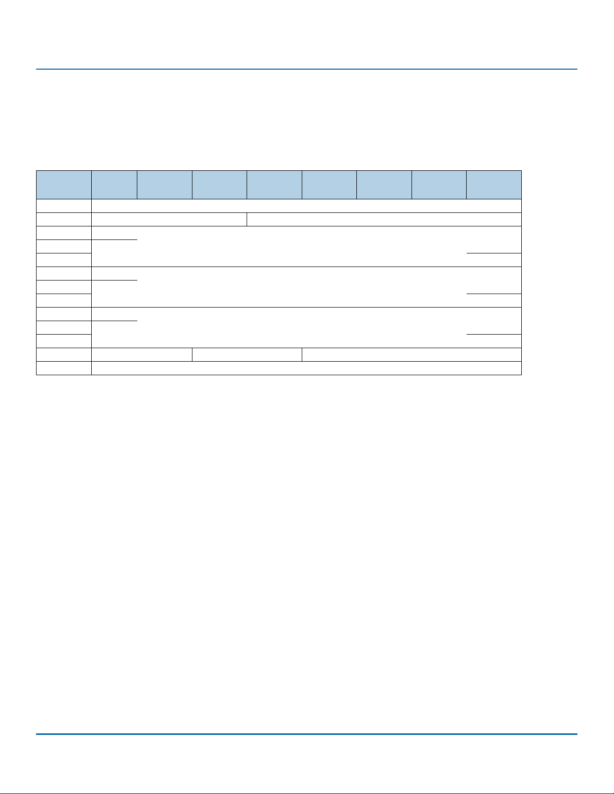
www.seagate.com Direct Access Block commands (SPC-6 and SBC-4)
3.6 GET PHYSICAL ELEMENT STATUS command
The GET PHYSICAL ELEMENT STATUS command (see table 60) requests that the device server return status information for physical elements
within the logical unit.
This command uses the SERVICE ACTION IN (16) CDB format (see SBC-4 clause A.2).
Table 60 GET PHYSICAL ELEMENT STATUS command
Bit
Byte
0 OPERATION CODE (9Eh)
1 Reserved SERVICE ACTION (17h)
2
5
6 (MSB)
9 (LSB)
10 (MSB)
13 (LSB)
14 FILTER Reserved REPORT TYPE
15 CONTROL
OPERATION CODE field and the SERVICE ACTION field
The OPERATION CODE field and the SERVICE ACTION field are defined in SPC-6 and shall be set to the values shown in table 60 for the GET
PHYSICAL ELEMENT STATUS command.
STARTING ELEMENT field
The STARTING ELEMENT field specifies the element identifier of the first physical element addressed by this command.
7 6 5 4 3 2 1 0
Reserved. . .
STARTING ELEMENT. . .
ALLOCATION LENGTH. . .
ALLOCATION LENGTH field
The ALLOCATION LENGTH field is defined in 2.2.6. In response to a GET PHYSICAL ELEMENT STATUS command, the device server may send less
data to the Data-In Buffer than is specified by the allocation length. If, in response to a GET PHYSICAL ELEMENT STATUS command, the device
server does not send sufficient data to the Data-In Buffer to satisfy the requirement of the application client, then, to retrieve additional
information, the application client may send additional GET PHYSICAL ELEMENT STATUS commands with different starting element values.
SCSI Commands Reference Manual, Rev. L 95
Page 96

www.seagate.com Direct Access Block commands (SPC-6 and SBC-4)
FILTER field
The FILTER field restricts the physical element status descriptors to return, as shown in table 61.
Table 61 FILTER field
Code Description
00b
01b
All others
REPORT TYPE field
The REPORT TYPE field specifies the type of physical element status descriptors to return as shown in table 62.
Table 62 REPORT TYPE field
Code Description
0h
1h
All others
CONTROL byte
The CONTROL byte is defined in 2.2.7
All physical status descriptors as specified by the other fields in the CDB.
Only physical element status descriptors for which the value of the PHYSICAL ELEMENT HEALTH field (see 5.8.2.2) is:
a) greater than or equal to 65h and less than or equal to CFh (i.e., outside manufacturer’s specification limit);
b) equal to FDh (i.e., all operations associated with storage element depopulation have completed and one or
more completed with error);
c) equal to FEh (i.e., an operation associated with storage element depopulation is in progress); or
d) equal to FFh (i.e., all operations associated with storage element depopulation have completed without error).
Reserved
Return descriptors for physical elements, based on the FILTER field
Return descriptors for storage elements, based on the FILTER field
Reserved
SCSI Commands Reference Manual, Rev. L 96
Page 97
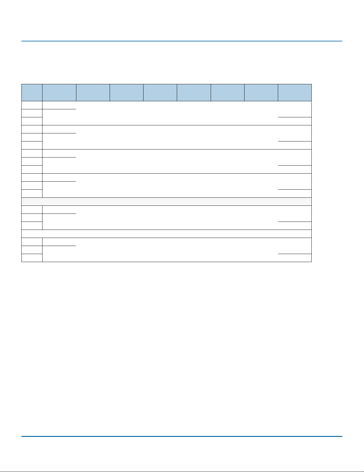
www.seagate.com Direct Access Block commands (SPC-6 and SBC-4)
3.6.1 GET PHYSICAL ELEMENT STATUS parameter data
The GET PHYSICAL ELEMENT STATUS parameter data (see table 59) contains a 32-byte header followed by zero or more physical element status
descriptors.
Table 63 GET PHYSICAL ELEMENT STATUS parameter data
Bit
Byte
0 (MSB)
3 (LSB)
4 (MSB)
7 (LSB)
8 (MSB)
11 (LSB)
12 (MSB)
31 (LSB)
32
63
n-32
n
7 6 5 4 3 2 1 0
NUMBER OF DESCRIPTORS. . .
NUMBER OF DESCRIPTORS RETURNED. . .
IDENTIFIER OF ELEMENT BEING DEPOPULATED. . .
Reserved. . .
Physical element status descriptor list
Physical element status descriptor [first] (see 3.6.2). . .
. . .
Physical element status descriptor [last] (see 3.6.2). . .
NUMBER OF DESCRIPTORS field
The NUMBER OF DESCRIPTORS field shall contain the number of descriptors in the element descriptors list. The element descriptors list is a list
of physical elements that:
a) meet the requirements of the REPORTING OPTIONS field;
b) meet the requirements of the FILTER field; and
c) have an element identifier that is greater than or equal to the element identifier specified by the STARTING ELEMENT field in the CDB.
The contents of the NUMBER OF DESCRIPTORS field are not altered based on the allocation length.
NUMBER OF DESCRIPTORS RETURNED field
The NUMBER OF DESCRIPTORS RETURNED field contains the number of valid physical element status descriptors returned in the parameter
data.
IDENTIFIER OF ELEMENT BEING DEPOPULATED field
The IDENTIFIER OF ELEMENT BEING DEPOPULATED field contains the element identifier of the element that has a physical element health set to
FEh (i.e., an operation associated with storage element depopulation is in progress). If the value of this field is set to zero, then no operation
associated with storage element depopulation is in progress.
As a result of processing considerations not defined by this standard, two GET PHYSICAL ELEMENT STATUS commands with identical values in
all CDB fields may result in two different values in the NUMBER OF DESCRIPTORS field.
The physical element status descriptors shall be sorted in ascending order of the element identifier.
SCSI Commands Reference Manual, Rev. L 97
Page 98

www.seagate.com Direct Access Block commands (SPC-6 and SBC-4)
3.6.2 Physical element status descriptor
The physical element status descriptor (see table 64) contains status information for a physical element.
Table 64 Physical element status descriptor format
Bit
Byte
0
3
4 (MSB)
7 (LSB)
8
12
13 Reserved RALWD
14 PHYSICAL ELEMENT TYPE
15 PHYSICAL ELEMENT HEALTH
16 (MSB)
23 (LSB)
24
31
ELEMENT IDENTIFIER field
The ELEMENT IDENTIFIER field contains the non-zero identifier of the physical element (e.g., storage element) associated with this physical
element status descriptor.
7 6 5 4 3 2 1 0
Reserved. . .
ELEMENT IDENTIFIER. . .
Reserved. . .
ASSOCIATED CAPACITY. . .
Reserved. . .
RALWD bit
A restoration allowed (RALWD) bit set to:
1 indicates that this storage element has been depopulated and is a candidate for being restored.
0 indicates that this storage element:
a) has not been depopulated; or
b) has been depopulated and is not a candidate for being restored.
SCSI Commands Reference Manual, Rev. L 98
Page 99

www.seagate.com Direct Access Block commands (SPC-6 and SBC-4)
PHYSICAL ELEMENT TYPE field
The PHYSICAL ELEMENT TYPE field indicates the type of the physical element associated with this physical element status descriptor, as
described in table 65.
Table 65 PHYSICAL ELEMENT TYPE field
Code Description
01h
All others
Storage element
Reserved
PHYSICAL ELEMENT HEALTH field
The PHYSICAL ELEMENT HEALTH field indicates the health of the physical element associated with this physical element status descriptor, as
described in table 66.
Table 66 PHYSICAL ELEMENT HEALTH field
Code Description
00h
01h to 63h
64h
65h to 63CF
D0h to FCh
FDh
FEh
FFh
Not reported.
a
The physical element health is within manufacturer’s specification limits.
The physical element health is at manufacturer’s specification limit.
a
The physical element health is outside manufacturer’s specification limit.
Reserved
All operations associated with storage element depopulation have completed and one or more completed with error.
An operation associated with storage element depopulation is in progress.
All operations associated with storage element depopulation have completed without error.
a The device server may implement a subset of these values.
ASSOCIATED CAPACITY field
The ASSOCIATED CAPACITY field indicates the number of logical blocks by which the capacity of the device is reduced if the physical element
associated with this physical element status descriptor becomes depopulated. A value of FFFF_FFFF_FFFF_FFFFh indicates that the number of
logical blocks by which the capacity is reduced is not specified.
SCSI Commands Reference Manual, Rev. L 99
Page 100
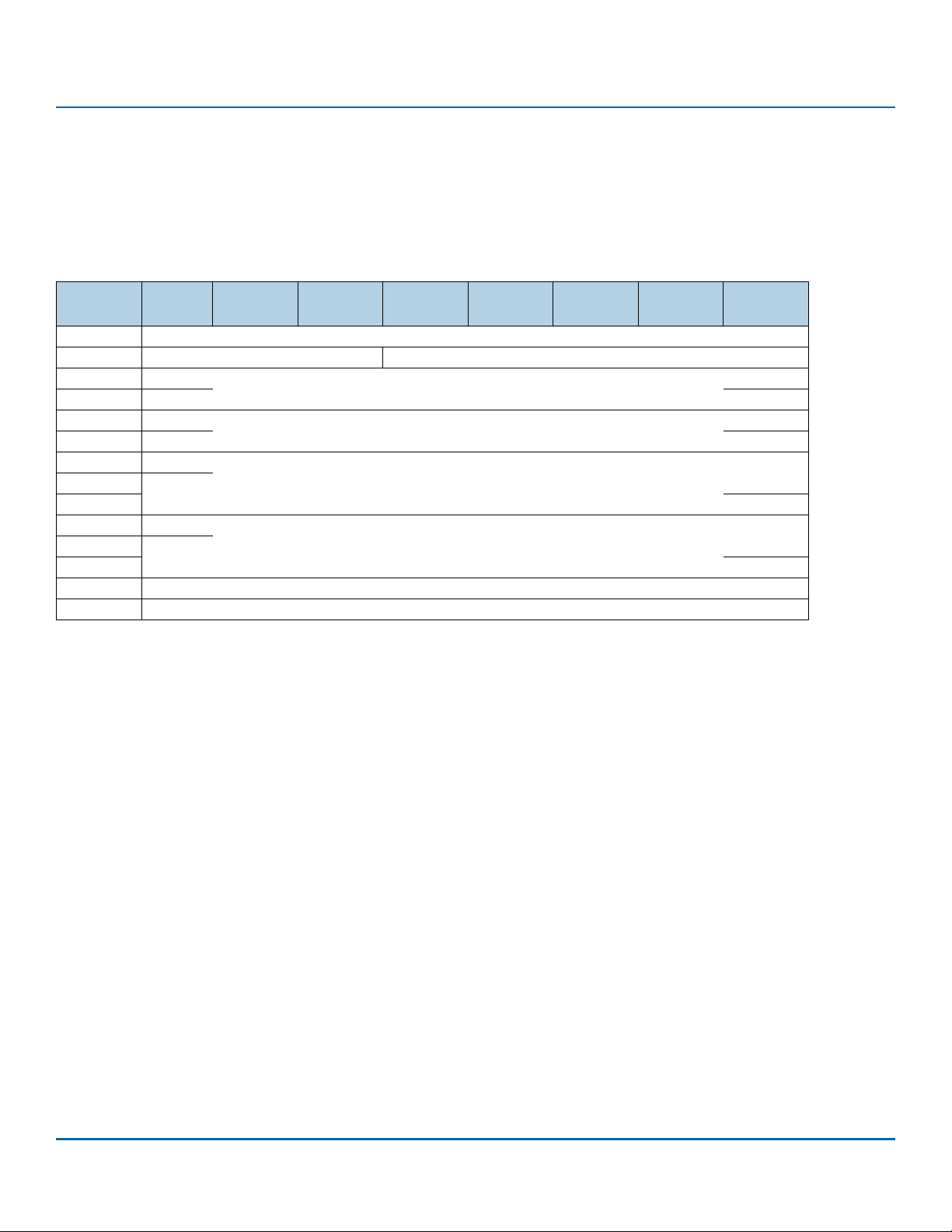
www.seagate.com Direct Access Block commands (SPC-6 and SBC-4)
3.7 GET STREAM STATUS command
The GET STREAM STATUS command (see table 67) requests that the device server transfer parameter data describing the status of streams (see
SBC-4) for the logical unit to the Data-In Buffer.
The device server may or may not process this command as an uninterrupted sequence of actions (e.g., if concurrent operations are occurring
that affect the status of streams, then the returned parameter data may be inconsistent or out of date).
Table 67 GET STREAM STATUS command
Bit
Byte
0 OPERATION CODE (9Eh)
1 Reserved SERVICE ACTION (16h)
2
3
4
5
6
9
10 (MSB)
13 (LSB)
14 Reserved
15 CONTROL
The OPERATION CODE field and the SERVICE ACTION field shall be set to the values shown in table 67 for the GET STREAM STATUS command.
OPERATION CODE field
The OPERATION CODE field contains the operation code of a command supported by the logical unit and shall be set to the value defined in
table 67.
7 6 5 4 3 2 1 0
Reserved
STARTING STREAM IDENTIFIER
Reserved. . .
ALLOCATION LENGTH. . .
SERVICE ACTION field
The SERVICE ACTION field is defined in 2.2.2 and set to the value defined in table 67.
STARTING STREAM IDENTIFIER field
The STARTING STREAM IDENTIFIER field specifies the stream identifier of the first stream addressed by this command (see 3.7.1.2). If the specified starting stream identifier exceeds the value indicated by the MAXIMUM NUMBER OF STREAMS field of the Block Limits VPD page (see
5.4.5), then the device server shall terminate the command with CHECK CONDITION status with the sense key set to ILLEGAL REQUEST and the
additional sense code set to ILLEGAL FIELD IN CDB.
The ALLOCATION LENGTH field is defined in 2.2.6 If, in response to a single GET STREAM STATUS command, the device server does not send sufficient data to the Data-In Buffer to satisfy the requirement of the application client, then the application client may send additional GET
STREAM STATUS commands with different starting stream identifier values to retrieve additional information.
SCSI Commands Reference Manual, Rev. L 100
 Loading...