


SCSI Interface
Ultra 320
Ultra 160
Product Manual, Volume 2


SCSI Interface
Ultra 320
Ultra 160
Product Manual, Volume 2

©1999–2004, Seagate Technology LLC All rights reserved
Publication number: 75789509, Rev. C
February 2004
Seagate and Seagate Technology are registered trademar ks of Seagate Technology LLC.
SeaTools, SeaFONE, SeaB OARD, SeaTDD, and the Wave logo are registe red trademarks
or trademarks of Sea gate Technology LLC . Other pr oduct name s are re gistered tr ademarks
or trademarks of their owners.
Seagate reserves the right to ch ange, witho ut notice, product offerings or spec ifications . No
part of this publication may be reproduc ed in any form w ithout wr itte n per mi ssio n of Seagate
Technology LLC.

Revision status summary sheet
Revision Date Sheets Affected
A Issue 01/31/2000 D. Ashby/G. Houlder 1/1, v thru viii, 1 thru 338.
Rev. B 04/22/2002 L. Newman/G. Houlder 1/1, v thru xvi, 1 thru 364.
Rev. C 02/13/2004 K. Schweiss/G. Holder 39, 83, 86, 94, 115, 123, 135-140,
Sheets Affected
141, 174, 202, 207, 210, 224-225,
227-228, 230, 232, 236, 238, 249,
252, 253, 255, 258, 260, 267, 280,
313, 325-326, 331-338, 345, 348,
351, 354-361, and 363.


Table of Contents
1.0 Interface requirements. . . . . . . . . . . . . . . . . . . . . . . . . . . . . . . . . . . . . . . . . . . . . . . . . . . . . . . . . . . . 1
1.1 How to use this interface manual . . . . . . . . . . . . . . . . . . . . . . . . . . . . . . . . . . . . . . . . . . . . . . 1
1.1.1 Scope of SCSI standards. . . . . . . . . . . . . . . . . . . . . . . . . . . . . . . . . . . . . . . . . . . . . 2
1.1.2 Applicable standards . . . . . . . . . . . . . . . . . . . . . . . . . . . . . . . . . . . . . . . . . . . . . . . . 3
1.2 General interface description. . . . . . . . . . . . . . . . . . . . . . . . . . . . . . . . . . . . . . . . . . . . . . . . . . 3
1.2.1 Glossary. . . . . . . . . . . . . . . . . . . . . . . . . . . . . . . . . . . . . . . . . . . . . . . . . . . . . . . . . . 4
1.2.2 Keywords. . . . . . . . . . . . . . . . . . . . . . . . . . . . . . . . . . . . . . . . . . . . . . . . . . . . . . . . 11
1.3 Physical interface characteristics. . . . . . . . . . . . . . . . . . . . . . . . . . . . . . . . . . . . . . . . . . . . . . 12
1.4 Summary of SCSI commands and messages. . . . . . . . . . . . . . . . . . . . . . . . . . . . . . . . . . . . 13
2.0 SCSI bus . . . . . . . . . . . . . . . . . . . . . . . . . . . . . . . . . . . . . . . . . . . . . . . . . . . . . . . . . . . . . . . . . . . . . . 17
2.1 SCSI bus signals overview . . . . . . . . . . . . . . . . . . . . . . . . . . . . . . . . . . . . . . . . . . . . . . . . . . 19
2.1.1 Drive select . . . . . . . . . . . . . . . . . . . . . . . . . . . . . . . . . . . . . . . . . . . . . . . . . . . . . . 21
2.1.2 Signal values . . . . . . . . . . . . . . . . . . . . . . . . . . . . . . . . . . . . . . . . . . . . . . . . . . . . . 21
2.2 Signal states . . . . . . . . . . . . . . . . . . . . . . . . . . . . . . . . . . . . . . . . . . . . . . . . . . . . . . . . . . . . . 21
2.2.1 SE signals . . . . . . . . . . . . . . . . . . . . . . . . . . . . . . . . . . . . . . . . . . . . . . . . . . . . . . . 21
2.2.2 LVD signals . . . . . . . . . . . . . . . . . . . . . . . . . . . . . . . . . . . . . . . . . . . . . . . . . . . . . . 21
2.3 OR-tied signals . . . . . . . . . . . . . . . . . . . . . . . . . . . . . . . . . . . . . . . . . . . . . . . . . . . . . . . . . . . 22
2.4 Signal sources. . . . . . . . . . . . . . . . . . . . . . . . . . . . . . . . . . . . . . . . . . . . . . . . . . . . . . . . . . . . 23
2.5 SCSI bus timing. . . . . . . . . . . . . . . . . . . . . . . . . . . . . . . . . . . . . . . . . . . . . . . . . . . . . . . . . . . 24
2.5.1 Arbitration delay. . . . . . . . . . . . . . . . . . . . . . . . . . . . . . . . . . . . . . . . . . . . . . . . . . . 29
2.5.2 ATN transmit setup time. . . . . . . . . . . . . . . . . . . . . . . . . . . . . . . . . . . . . . . . . . . . . 29
2.5.3 ATN receive setup time . . . . . . . . . . . . . . . . . . . . . . . . . . . . . . . . . . . . . . . . . . . . . 29
2.5.4 Bus clear delay. . . . . . . . . . . . . . . . . . . . . . . . . . . . . . . . . . . . . . . . . . . . . . . . . . . . 29
2.5.5 Bus free delay . . . . . . . . . . . . . . . . . . . . . . . . . . . . . . . . . . . . . . . . . . . . . . . . . . . . 29
2.5.6 Bus set delay . . . . . . . . . . . . . . . . . . . . . . . . . . . . . . . . . . . . . . . . . . . . . . . . . . . . . 30
2.5.7 Bus settle delay . . . . . . . . . . . . . . . . . . . . . . . . . . . . . . . . . . . . . . . . . . . . . . . . . . . 30
2.5.8 Cable skew delay. . . . . . . . . . . . . . . . . . . . . . . . . . . . . . . . . . . . . . . . . . . . . . . . . . 30
2.5.9 Chip noise in receiver. . . . . . . . . . . . . . . . . . . . . . . . . . . . . . . . . . . . . . . . . . . . . . . 30
2.5.10 Clock jitter . . . . . . . . . . . . . . . . . . . . . . . . . . . . . . . . . . . . . . . . . . . . . . . . . . . . . . . 30
2.5.11 De-skewed data valid window . . . . . . . . . . . . . . . . . . . . . . . . . . . . . . . . . . . . . . . . 30
2.5.12 Flow control receive hold time . . . . . . . . . . . . . . . . . . . . . . . . . . . . . . . . . . . . . . . . 30
2.5.13 Flow control receive setup time . . . . . . . . . . . . . . . . . . . . . . . . . . . . . . . . . . . . . . . 30
2.5.14 Flow control transmit hold time . . . . . . . . . . . . . . . . . . . . . . . . . . . . . . . . . . . . . . . 30
2.5.15 Flow control transmit setup time . . . . . . . . . . . . . . . . . . . . . . . . . . . . . . . . . . . . . . 31
2.5.16 pCRC receive hold time . . . . . . . . . . . . . . . . . . . . . . . . . . . . . . . . . . . . . . . . . . . . . 31
2.5.17 pCRC receive setup time . . . . . . . . . . . . . . . . . . . . . . . . . . . . . . . . . . . . . . . . . . . . 31
2.5.18 pCRC transmit hold time . . . . . . . . . . . . . . . . . . . . . . . . . . . . . . . . . . . . . . . . . . . . 31
2.5.19 pCRC transmit setup time . . . . . . . . . . . . . . . . . . . . . . . . . . . . . . . . . . . . . . . . . . . 31
2.5.20 Data release delay . . . . . . . . . . . . . . . . . . . . . . . . . . . . . . . . . . . . . . . . . . . . . . . . . 31
2.5.21 DIFFSENS voltage filter time. . . . . . . . . . . . . . . . . . . . . . . . . . . . . . . . . . . . . . . . . 31
2.5.22 Physical disconnection delay. . . . . . . . . . . . . . . . . . . . . . . . . . . . . . . . . . . . . . . . . 31
2.5.23 Power on to selection. . . . . . . . . . . . . . . . . . . . . . . . . . . . . . . . . . . . . . . . . . . . . . . 31
2.5.24 QAS arbitration delay. . . . . . . . . . . . . . . . . . . . . . . . . . . . . . . . . . . . . . . . . . . . . . . 31
2.5.25 QAS assertion delay . . . . . . . . . . . . . . . . . . . . . . . . . . . . . . . . . . . . . . . . . . . . . . . 32
2.5.26 QAS release delay . . . . . . . . . . . . . . . . . . . . . . . . . . . . . . . . . . . . . . . . . . . . . . . . . 32
2.5.27 QAS non-data phase REQ(ACK) period . . . . . . . . . . . . . . . . . . . . . . . . . . . . . . . . 32
2.5.28 Receive assertion period . . . . . . . . . . . . . . . . . . . . . . . . . . . . . . . . . . . . . . . . . . . . 32
2.5.29 Receive hold time. . . . . . . . . . . . . . . . . . . . . . . . . . . . . . . . . . . . . . . . . . . . . . . . . . 32
2.5.30 Receive internal hold time . . . . . . . . . . . . . . . . . . . . . . . . . . . . . . . . . . . . . . . . . . . 32
2.5.31 Receive internal setup time . . . . . . . . . . . . . . . . . . . . . . . . . . . . . . . . . . . . . . . . . . 32
2.5.32 Receive negation period . . . . . . . . . . . . . . . . . . . . . . . . . . . . . . . . . . . . . . . . . . . . 32
2.5.33 Receive setup time. . . . . . . . . . . . . . . . . . . . . . . . . . . . . . . . . . . . . . . . . . . . . . . . . 33
SCSI Interface Product Manual, Rev. C (Draft 03) v

2.5.34 Receive REQ(ACK) period tolerance . . . . . . . . . . . . . . . . . . . . . . . . . . . . . . . . . . . 33
2.5.35 Receive REQ assertion period with P_CRCA transitioning . . . . . . . . . . . . . . . . . . 33
2.5.36 Receive REQ negation period with P_CRCA transitioning. . . . . . . . . . . . . . . . . . . 33
2.5.37 Receive skew compensation . . . . . . . . . . . . . . . . . . . . . . . . . . . . . . . . . . . . . . . . . 33
2.5.38 Receiver amplitude time skew . . . . . . . . . . . . . . . . . . . . . . . . . . . . . . . . . . . . . . . . 33
2.5.39 REQ(ACK) period. . . . . . . . . . . . . . . . . . . . . . . . . . . . . . . . . . . . . . . . . . . . . . . . . . 33
2.5.40 Reset delay. . . . . . . . . . . . . . . . . . . . . . . . . . . . . . . . . . . . . . . . . . . . . . . . . . . . . . . 33
2.5.41 Reset hold time. . . . . . . . . . . . . . . . . . . . . . . . . . . . . . . . . . . . . . . . . . . . . . . . . . . . 34
2.5.42 Reset to selection. . . . . . . . . . . . . . . . . . . . . . . . . . . . . . . . . . . . . . . . . . . . . . . . . . 34
2.5.43 Residual skew error . . . . . . . . . . . . . . . . . . . . . . . . . . . . . . . . . . . . . . . . . . . . . . . . 34
2.5.44 Selection abort time . . . . . . . . . . . . . . . . . . . . . . . . . . . . . . . . . . . . . . . . . . . . . . . . 34
2.5.45 Selection timeout delay . . . . . . . . . . . . . . . . . . . . . . . . . . . . . . . . . . . . . . . . . . . . . 34
2.5.46 Signal timing skew . . . . . . . . . . . . . . . . . . . . . . . . . . . . . . . . . . . . . . . . . . . . . . . . . 34
2.5.47 Skew correction range . . . . . . . . . . . . . . . . . . . . . . . . . . . . . . . . . . . . . . . . . . . . . . 34
2.5.48 Strobe offset tolerance . . . . . . . . . . . . . . . . . . . . . . . . . . . . . . . . . . . . . . . . . . . . . . 34
2.5.49 System deskew delay. . . . . . . . . . . . . . . . . . . . . . . . . . . . . . . . . . . . . . . . . . . . . . . 34
2.5.50 System noise at launch . . . . . . . . . . . . . . . . . . . . . . . . . . . . . . . . . . . . . . . . . . . . . 35
2.5.51 System noise at receiver . . . . . . . . . . . . . . . . . . . . . . . . . . . . . . . . . . . . . . . . . . . . 35
2.5.52 Time asymmetry. . . . . . . . . . . . . . . . . . . . . . . . . . . . . . . . . . . . . . . . . . . . . . . . . . . 35
2.5.53 Transmit assertion period . . . . . . . . . . . . . . . . . . . . . . . . . . . . . . . . . . . . . . . . . . . . 35
2.5.54 Transmit hold time . . . . . . . . . . . . . . . . . . . . . . . . . . . . . . . . . . . . . . . . . . . . . . . . . 35
2.5.55 Transmit ISI compensation. . . . . . . . . . . . . . . . . . . . . . . . . . . . . . . . . . . . . . . . . . . 35
2.5.56 Transmit negation period . . . . . . . . . . . . . . . . . . . . . . . . . . . . . . . . . . . . . . . . . . . . 35
2.5.57 Transmit setup time . . . . . . . . . . . . . . . . . . . . . . . . . . . . . . . . . . . . . . . . . . . . . . . . 35
2.5.58 Transmit REQ(ACK) period tolerance . . . . . . . . . . . . . . . . . . . . . . . . . . . . . . . . . . 35
2.5.59 Transmit REQ assertion period with P_CRCA transitioning. . . . . . . . . . . . . . . . . . 36
2.5.60 Transmit REQ negation period with P_CRCA transitioning . . . . . . . . . . . . . . . . . . 36
2.5.61 Transmitter skew . . . . . . . . . . . . . . . . . . . . . . . . . . . . . . . . . . . . . . . . . . . . . . . . . . 36
2.5.62 Transmitter time asymmetry . . . . . . . . . . . . . . . . . . . . . . . . . . . . . . . . . . . . . . . . . . 36
2.6 Measurement points. . . . . . . . . . . . . . . . . . . . . . . . . . . . . . . . . . . . . . . . . . . . . . . . . . . . . . . . 36
2.6.1 SE Fast-5 and Fast-10 measurement points . . . . . . . . . . . . . . . . . . . . . . . . . . . . . 36
2.6.2 SE Fast-20 measurement points . . . . . . . . . . . . . . . . . . . . . . . . . . . . . . . . . . . . . . 36
2.6.3 LVD measurement points. . . . . . . . . . . . . . . . . . . . . . . . . . . . . . . . . . . . . . . . . . . . 37
2.7 Clocking methods for data transfers . . . . . . . . . . . . . . . . . . . . . . . . . . . . . . . . . . . . . . . . . . . 37
2.8 Paced transfer on a SCSI bus . . . . . . . . . . . . . . . . . . . . . . . . . . . . . . . . . . . . . . . . . . . . . . . . 39
2.9 Data transfer modes. . . . . . . . . . . . . . . . . . . . . . . . . . . . . . . . . . . . . . . . . . . . . . . . . . . . . . . . 40
2.9.1 Asynchronous transfers . . . . . . . . . . . . . . . . . . . . . . . . . . . . . . . . . . . . . . . . . . . . . 40
2.9.2 Synchronous transfers . . . . . . . . . . . . . . . . . . . . . . . . . . . . . . . . . . . . . . . . . . . . . . 40
2.9.3 Paced transfers . . . . . . . . . . . . . . . . . . . . . . . . . . . . . . . . . . . . . . . . . . . . . . . . . . . 40
2.10 ST DATA phase parallel transfers . . . . . . . . . . . . . . . . . . . . . . . . . . . . . . . . . . . . . . . . . . . . . 40
2.11 DT DATA phase parallel transfers . . . . . . . . . . . . . . . . . . . . . . . . . . . . . . . . . . . . . . . . . . . . . 40
2.11.1 Data group transfers. . . . . . . . . . . . . . . . . . . . . . . . . . . . . . . . . . . . . . . . . . . . . . . . 40
2.11.2 Information unit transfers . . . . . . . . . . . . . . . . . . . . . . . . . . . . . . . . . . . . . . . . . . . . 41
2.12 Negotiation. . . . . . . . . . . . . . . . . . . . . . . . . . . . . . . . . . . . . . . . . . . . . . . . . . . . . . . . . . . . . . . 42
2.12.1 Negotiation algorithm . . . . . . . . . . . . . . . . . . . . . . . . . . . . . . . . . . . . . . . . . . . . . . . 42
2.12.2 When to negotiate . . . . . . . . . . . . . . . . . . . . . . . . . . . . . . . . . . . . . . . . . . . . . . . . . 42
2.12.3 Negotiable fields. . . . . . . . . . . . . . . . . . . . . . . . . . . . . . . . . . . . . . . . . . . . . . . . . . . 43
2.12.4 Transfer agreements . . . . . . . . . . . . . . . . . . . . . . . . . . . . . . . . . . . . . . . . . . . . . . . 44
2.12.5 Transfer period factor . . . . . . . . . . . . . . . . . . . . . . . . . . . . . . . . . . . . . . . . . . . . . . . 45
2.12.6 REQ/ACK offset . . . . . . . . . . . . . . . . . . . . . . . . . . . . . . . . . . . . . . . . . . . . . . . . . . . 46
2.12.7 Transfer width exponent. . . . . . . . . . . . . . . . . . . . . . . . . . . . . . . . . . . . . . . . . . . . . 46
2.12.8 Protocol options . . . . . . . . . . . . . . . . . . . . . . . . . . . . . . . . . . . . . . . . . . . . . . . . . . . 47
2.12.8.1 IU_REQ . . . . . . . . . . . . . . . . . . . . . . . . . . . . . . . . . . . . . . . . . . . . . . . . 47
2.12.8.2 DT_REQ. . . . . . . . . . . . . . . . . . . . . . . . . . . . . . . . . . . . . . . . . . . . . . . . 48
2.12.8.3 QAS_REQ . . . . . . . . . . . . . . . . . . . . . . . . . . . . . . . . . . . . . . . . . . . . . . 48
vi SCSI Interface Product Manual, Rev. C (Draft 03)

2.12.8.4 HOLD_MCS. . . . . . . . . . . . . . . . . . . . . . . . . . . . . . . . . . . . . . . . . . . . . 48
2.12.8.5 WR_FLOW. . . . . . . . . . . . . . . . . . . . . . . . . . . . . . . . . . . . . . . . . . . . . . 49
2.12.8.6 RD_STRM . . . . . . . . . . . . . . . . . . . . . . . . . . . . . . . . . . . . . . . . . . . . . . 49
2.12.8.7 RTI (Retain Training Information) . . . . . . . . . . . . . . . . . . . . . . . . . . . . 49
2.12.8.8 PCOMP_EN. . . . . . . . . . . . . . . . . . . . . . . . . . . . . . . . . . . . . . . . . . . . . 49
2.12.9 Negotiable field combinations . . . . . . . . . . . . . . . . . . . . . . . . . . . . . . . . . . . . . . . . 50
2.12.10 Message restrictions . . . . . . . . . . . . . . . . . . . . . . . . . . . . . . . . . . . . . . . . . . . . . . . 51
2.12.11 Negotiation message sequences. . . . . . . . . . . . . . . . . . . . . . . . . . . . . . . . . . . . . . 51
3.0 Logical characteristics. . . . . . . . . . . . . . . . . . . . . . . . . . . . . . . . . . . . . . . . . . . . . . . . . . . . . . . . . . . 53
3.1 SCSI bus phases overview . . . . . . . . . . . . . . . . . . . . . . . . . . . . . . . . . . . . . . . . . . . . . . . . . . 53
3.1.1 BUS FREE phase . . . . . . . . . . . . . . . . . . . . . . . . . . . . . . . . . . . . . . . . . . . . . . . . . 53
3.1.1.1 Unexpected and expected bus free phases. . . . . . . . . . . . . . . . . . . . . 53
3.1.1.2 Expected bus free phases . . . . . . . . . . . . . . . . . . . . . . . . . . . . . . . . . . 54
3.1.2 Arbitration and QAS overview . . . . . . . . . . . . . . . . . . . . . . . . . . . . . . . . . . . . . . . . 54
3.1.2.1 Normal ARBITRATION phase . . . . . . . . . . . . . . . . . . . . . . . . . . . . . . . 55
3.1.2.2 QAS protocol . . . . . . . . . . . . . . . . . . . . . . . . . . . . . . . . . . . . . . . . . . . . 56
3.1.2.3 QAS phase overview . . . . . . . . . . . . . . . . . . . . . . . . . . . . . . . . . . . . . . 56
3.2 SELECTION phase . . . . . . . . . . . . . . . . . . . . . . . . . . . . . . . . . . . . . . . . . . . . . . . . . . . . . . . . 58
3.2.1 Selection overview. . . . . . . . . . . . . . . . . . . . . . . . . . . . . . . . . . . . . . . . . . . . . . . . . 58
3.2.1.1 Selection using attention condition . . . . . . . . . . . . . . . . . . . . . . . . . . . 58
3.2.1.1.1 Starting the SELECTION phase when using
attention condition . . . . . . . . . . . . . . . . . . . . . . . . . . . . 58
3.2.1.1.2 Information unit transfers disabled . . . . . . . . . . . . . . . 58
3.2.1.1.3 Information unit transfers enabled. . . . . . . . . . . . . . . . 58
3.2.1.1.4 Selection using attention condition timeout
procedure . . . . . . . . . . . . . . . . . . . . . . . . . . . . . . . . . . 59
3.2.1.2 Selection without using attention condition . . . . . . . . . . . . . . . . . . . . . 59
3.2.1.2.1 Information unit transfers disabled or enabled . . . . . . 59
3.2.1.2.2 Selection without using attenti on condi tion
time-out procedure . . . . . . . . . . . . . . . . . . . . . . . . . . . 60
3.3 RESELECTION phase . . . . . . . . . . . . . . . . . . . . . . . . . . . . . . . . . . . . . . . . . . . . . . . . . . . . . 60
3.3.1 RESELECTION phase overview . . . . . . . . . . . . . . . . . . . . . . . . . . . . . . . . . . . . . . 60
3.3.2 Physical reconnection . . . . . . . . . . . . . . . . . . . . . . . . . . . . . . . . . . . . . . . . . . . . . . 60
3.3.3 Physical reconnection timeout procedure . . . . . . . . . . . . . . . . . . . . . . . . . . . . . . . 61
3.4 SCSI bus fairness . . . . . . . . . . . . . . . . . . . . . . . . . . . . . . . . . . . . . . . . . . . . . . . . . . . . . . . . . 61
3.5 Information transfer phases. . . . . . . . . . . . . . . . . . . . . . . . . . . . . . . . . . . . . . . . . . . . . . . . . . 62
3.5.1 Asynchronous transfer. . . . . . . . . . . . . . . . . . . . . . . . . . . . . . . . . . . . . . . . . . . . . . 63
3.5.2 Synchronous transfer. . . . . . . . . . . . . . . . . . . . . . . . . . . . . . . . . . . . . . . . . . . . . . . 63
3.5.2.1 ST synchronous data transfer . . . . . . . . . . . . . . . . . . . . . . . . . . . . . . . 63
3.5.2.2 DT synchronous transfer . . . . . . . . . . . . . . . . . . . . . . . . . . . . . . . . . . . 64
3.5.2.2.1 Information unit transfer . . . . . . . . . . . . . . . . . . . . . . . 64
3.5.2.2.2 Data group data field transfer . . . . . . . . . . . . . . . . . . . 66
3.5.3 Paced transfer . . . . . . . . . . . . . . . . . . . . . . . . . . . . . . . . . . . . . . . . . . . . . . . . . . . . 70
3.5.3.1 Paced transfer training pattern. . . . . . . . . . . . . . . . . . . . . . . . . . . . . . . 71
3.5.3.1.1 DT DATA IN phase training pattern. . . . . . . . . . . . . . . 71
3.5.3.1.2 DT DATA OUT phase training pattern. . . . . . . . . . . . . 72
3.5.3.2 P1 data valid/invalid state transitions. . . . . . . . . . . . . . . . . . . . . . . . . . 73
3.5.3.2.1 Starting pacing transfers at end of training pattern . . . 74
3.5.3.2.2 Starting pacing transfers with no training pattern . . . . 74
3.5.3.2.3 Ending pacing transfers. . . . . . . . . . . . . . . . . . . . . . . . 75
3.5.3.3 Paced information unit transfer . . . . . . . . . . . . . . . . . . . . . . . . . . . . . . 75
3.5.3.4 Deskewing . . . . . . . . . . . . . . . . . . . . . . . . . . . . . . . . . . . . . . . . . . . . . . 76
3.5.4 Wide transfer . . . . . . . . . . . . . . . . . . . . . . . . . . . . . . . . . . . . . . . . . . . . . . . . . . . . . 76
3.6 COMMAND phase. . . . . . . . . . . . . . . . . . . . . . . . . . . . . . . . . . . . . . . . . . . . . . . . . . . . . . . . . 77
SCSI Interface Product Manual, Rev. C (Draft 03) vii

3.6.1 COMMAND phase description . . . . . . . . . . . . . . . . . . . . . . . . . . . . . . . . . . . . . . . . 77
3.6.2 COMMAND phase exception condition handling . . . . . . . . . . . . . . . . . . . . . . . . . . 77
3.7 DATA phase. . . . . . . . . . . . . . . . . . . . . . . . . . . . . . . . . . . . . . . . . . . . . . . . . . . . . . . . . . . . . . 77
3.7.1 DATA phase overview . . . . . . . . . . . . . . . . . . . . . . . . . . . . . . . . . . . . . . . . . . . . . . 77
3.7.2 DT DATA IN phase. . . . . . . . . . . . . . . . . . . . . . . . . . . . . . . . . . . . . . . . . . . . . . . . . 78
3.7.3 DT DATA OUT phase. . . . . . . . . . . . . . . . . . . . . . . . . . . . . . . . . . . . . . . . . . . . . . . 78
3.7.4 ST DATA IN phase. . . . . . . . . . . . . . . . . . . . . . . . . . . . . . . . . . . . . . . . . . . . . . . . . 78
3.7.5 ST DATA OUT phase. . . . . . . . . . . . . . . . . . . . . . . . . . . . . . . . . . . . . . . . . . . . . . . 78
3.8 STATUS phase . . . . . . . . . . . . . . . . . . . . . . . . . . . . . . . . . . . . . . . . . . . . . . . . . . . . . . . . . . . 78
3.8.1 STATUS phase description . . . . . . . . . . . . . . . . . . . . . . . . . . . . . . . . . . . . . . . . . . 78
3.8.2 STATUS phase exception condition handling . . . . . . . . . . . . . . . . . . . . . . . . . . . . 78
3.9 MESSAGE phase. . . . . . . . . . . . . . . . . . . . . . . . . . . . . . . . . . . . . . . . . . . . . . . . . . . . . . . . . . 78
3.9.1 MESSAGE phase overview . . . . . . . . . . . . . . . . . . . . . . . . . . . . . . . . . . . . . . . . . . 78
3.9.2 MESSAGE IN phase . . . . . . . . . . . . . . . . . . . . . . . . . . . . . . . . . . . . . . . . . . . . . . . 79
3.9.2.1 MESSAGE IN phase exception condition handling . . . . . . . . . . . . . . . 79
3.9.3 MESSAGE OUT phase . . . . . . . . . . . . . . . . . . . . . . . . . . . . . . . . . . . . . . . . . . . . . 79
3.9.3.1 MESSAGE OUT phase exception condition handling . . . . . . . . . . . . . 79
3.10 Signal restrictions between phases . . . . . . . . . . . . . . . . . . . . . . . . . . . . . . . . . . . . . . . . . . . . 80
3.11 SCSI bus phase sequences. . . . . . . . . . . . . . . . . . . . . . . . . . . . . . . . . . . . . . . . . . . . . . . . . . 80
3.11.1 SCSI bus phase sequences overview . . . . . . . . . . . . . . . . . . . . . . . . . . . . . . . . . . 80
3.11.2 Phase sequences for physical reconnection and selection using attention
condition with information unit transfers disabled. . . . . . . . . . . . . . . . . . . . . . . . . . 81
3.11.3 Phase sequences for selection without using attention condition with
information unit transfers disabled . . . . . . . . . . . . . . . . . . . . . . . . . . . . . . . . . . . . . 81
3.11.4 Phase sequences for physical reconnection or selection without using
attention condition with information unit transfers enabled. . . . . . . . . . . . . . . . . . . 83
3.11.5 Phase sequences for physical selection using attention condition with
information unit transfers enabled . . . . . . . . . . . . . . . . . . . . . . . . . . . . . . . . . . . . . 84
3.12 Data bus protection . . . . . . . . . . . . . . . . . . . . . . . . . . . . . . . . . . . . . . . . . . . . . . . . . . . . . . . . 84
3.12.1 Data bus protection overview. . . . . . . . . . . . . . . . . . . . . . . . . . . . . . . . . . . . . . . . . 84
3.12.2 ST data bus protection using parity . . . . . . . . . . . . . . . . . . . . . . . . . . . . . . . . . . . . 84
3.12.3 DT data bus protection using CRC. . . . . . . . . . . . . . . . . . . . . . . . . . . . . . . . . . . . . 85
3.12.3.1 DT data bus protection using CRC overview . . . . . . . . . . . . . . . . . . . . 85
3.12.3.2 Error detection capabilities. . . . . . . . . . . . . . . . . . . . . . . . . . . . . . . . . . 85
3.12.3.3 Order of bytes in the CRC field . . . . . . . . . . . . . . . . . . . . . . . . . . . . . . 85
4.0 Message system specification. . . . . . . . . . . . . . . . . . . . . . . . . . . . . . . . . . . . . . . . . . . . . . . . . . . . . 87
4.1 General message protocols and formats. . . . . . . . . . . . . . . . . . . . . . . . . . . . . . . . . . . . . . . . 87
4.2 Message formats . . . . . . . . . . . . . . . . . . . . . . . . . . . . . . . . . . . . . . . . . . . . . . . . . . . . . . . . . . 88
4.2.1 One-byte messages . . . . . . . . . . . . . . . . . . . . . . . . . . . . . . . . . . . . . . . . . . . . . . . . 88
4.2.2 Two-byte messages . . . . . . . . . . . . . . . . . . . . . . . . . . . . . . . . . . . . . . . . . . . . . . . . 88
4.2.3 Extended messages. . . . . . . . . . . . . . . . . . . . . . . . . . . . . . . . . . . . . . . . . . . . . . . . 88
4.3 Message categories. . . . . . . . . . . . . . . . . . . . . . . . . . . . . . . . . . . . . . . . . . . . . . . . . . . . . . . . 89
4.3.1 LINK CONTROL MESSAGES . . . . . . . . . . . . . . . . . . . . . . . . . . . . . . . . . . . . . . . . 90
4.3.2 DISCONNECT . . . . . . . . . . . . . . . . . . . . . . . . . . . . . . . . . . . . . . . . . . . . . . . . . . . . 91
4.3.3 IDENTIFY. . . . . . . . . . . . . . . . . . . . . . . . . . . . . . . . . . . . . . . . . . . . . . . . . . . . . . . . 91
4.3.4 IGNORE WIDE RESIDUE . . . . . . . . . . . . . . . . . . . . . . . . . . . . . . . . . . . . . . . . . . . 92
4.3.5 INITIATOR DETECTED ERROR . . . . . . . . . . . . . . . . . . . . . . . . . . . . . . . . . . . . . . 93
4.3.6 LINKED COMMAND COMPLETE . . . . . . . . . . . . . . . . . . . . . . . . . . . . . . . . . . . . . 93
4.3.7 MESSAGE PARITY ERROR . . . . . . . . . . . . . . . . . . . . . . . . . . . . . . . . . . . . . . . . . 93
4.3.8 MESSAGE REJECT. . . . . . . . . . . . . . . . . . . . . . . . . . . . . . . . . . . . . . . . . . . . . . . . 93
4.3.9 MODIFY DATA POINTER . . . . . . . . . . . . . . . . . . . . . . . . . . . . . . . . . . . . . . . . . . . 94
4.3.10 MODIFY BIDIRECTIONAL DATA POINTER . . . . . . . . . . . . . . . . . . . . . . . . . . . . . 94
4.3.11 NO OPERATION . . . . . . . . . . . . . . . . . . . . . . . . . . . . . . . . . . . . . . . . . . . . . . . . . . 95
4.3.12 PARALLEL PROTOCOL REQUEST . . . . . . . . . . . . . . . . . . . . . . . . . . . . . . . . . . . 96
viii SCSI Interface Product Manual, Rev. C (Draft 03)

4.3.12.1 PARALLEL PROTOCOL REQUEST . . . . . . . . . . . . . . . . . . . . . . . . . . 99
4.3.13 QAS REQUEST. . . . . . . . . . . . . . . . . . . . . . . . . . . . . . . . . . . . . . . . . . . . . . . . . . 100
4.3.14 RESTORE POINTERS . . . . . . . . . . . . . . . . . . . . . . . . . . . . . . . . . . . . . . . . . . . . 100
4.3.15 SAVE DATA POINTERS . . . . . . . . . . . . . . . . . . . . . . . . . . . . . . . . . . . . . . . . . . . 100
4.3.16 SYNCHRONOUS DATA TRANSFER REQUEST . . . . . . . . . . . . . . . . . . . . . . . . 101
4.3.16.1 Target initiated SDTR negotiation . . . . . . . . . . . . . . . . . . . . . . . . . . . 103
4.3.16.2 Initiator initiated SDTR negotiation . . . . . . . . . . . . . . . . . . . . . . . . . . 103
4.3.17 TASK COMPLETE. . . . . . . . . . . . . . . . . . . . . . . . . . . . . . . . . . . . . . . . . . . . . . . . 104
4.3.18 WIDE DATA TRANSFER REQUEST . . . . . . . . . . . . . . . . . . . . . . . . . . . . . . . . . 104
4.3.18.1 Target initiated WDTR negotiation. . . . . . . . . . . . . . . . . . . . . . . . . . . 106
4.3.18.2 Initiator initiated Wide Data Transfer Request (WDTR) negotiation . 106
4.4 Task attribute messages . . . . . . . . . . . . . . . . . . . . . . . . . . . . . . . . . . . . . . . . . . . . . . . . . . . 107
4.4.1 Task attribute message overview and codes. . . . . . . . . . . . . . . . . . . . . . . . . . . . 107
4.4.2 ACA (AUTO CONTINGENT ALLEGIANCE) . . . . . . . . . . . . . . . . . . . . . . . . . . . . 108
4.4.3 HEAD OF QUEUE. . . . . . . . . . . . . . . . . . . . . . . . . . . . . . . . . . . . . . . . . . . . . . . . 109
4.4.4 ORDERED. . . . . . . . . . . . . . . . . . . . . . . . . . . . . . . . . . . . . . . . . . . . . . . . . . . . . . 109
4.4.5 SIMPLE . . . . . . . . . . . . . . . . . . . . . . . . . . . . . . . . . . . . . . . . . . . . . . . . . . . . . . . . 109
4.5 Task management messages . . . . . . . . . . . . . . . . . . . . . . . . . . . . . . . . . . . . . . . . . . . . . . . 110
4.5.1 Task management message codes. . . . . . . . . . . . . . . . . . . . . . . . . . . . . . . . . . . 110
4.5.2 ABORT TASK . . . . . . . . . . . . . . . . . . . . . . . . . . . . . . . . . . . . . . . . . . . . . . . . . . . 110
4.5.3 ABORT TASK SET . . . . . . . . . . . . . . . . . . . . . . . . . . . . . . . . . . . . . . . . . . . . . . . 111
4.5.4 CLEAR ACA. . . . . . . . . . . . . . . . . . . . . . . . . . . . . . . . . . . . . . . . . . . . . . . . . . . . . 111
4.5.5 CLEAR TASK SET. . . . . . . . . . . . . . . . . . . . . . . . . . . . . . . . . . . . . . . . . . . . . . . . 111
4.5.6 LOGICAL UNIT RESET. . . . . . . . . . . . . . . . . . . . . . . . . . . . . . . . . . . . . . . . . . . . 111
4.5.7 TARGET RESET . . . . . . . . . . . . . . . . . . . . . . . . . . . . . . . . . . . . . . . . . . . . . . . . . 111
5.0 Miscellaneous SCSI bus characteristics . . . . . . . . . . . . . . . . . . . . . . . . . . . . . . . . . . . . . . . . . . . 113
5.1 Attention condition. . . . . . . . . . . . . . . . . . . . . . . . . . . . . . . . . . . . . . . . . . . . . . . . . . . . . . . . 113
5.2 Bus reset condition . . . . . . . . . . . . . . . . . . . . . . . . . . . . . . . . . . . . . . . . . . . . . . . . . . . . . . . 114
5.3 Hard reset . . . . . . . . . . . . . . . . . . . . . . . . . . . . . . . . . . . . . . . . . . . . . . . . . . . . . . . . . . . . . . 114
5.4 Reset events . . . . . . . . . . . . . . . . . . . . . . . . . . . . . . . . . . . . . . . . . . . . . . . . . . . . . . . . . . . . 115
5.4.1 Bus reset event . . . . . . . . . . . . . . . . . . . . . . . . . . . . . . . . . . . . . . . . . . . . . . . . . . 115
5.4.2 Power on reset event. . . . . . . . . . . . . . . . . . . . . . . . . . . . . . . . . . . . . . . . . . . . . . 115
5.4.3 Target reset event . . . . . . . . . . . . . . . . . . . . . . . . . . . . . . . . . . . . . . . . . . . . . . . . 115
5.4.4 Transceiver mode change reset event. . . . . . . . . . . . . . . . . . . . . . . . . . . . . . . . . 115
5.5 Asynchronous condition recovery . . . . . . . . . . . . . . . . . . . . . . . . . . . . . . . . . . . . . . . . . . . . 115
5.5.1 SCSI pointers. . . . . . . . . . . . . . . . . . . . . . . . . . . . . . . . . . . . . . . . . . . . . . . . . . . . 116
5.5.2 Active pointers . . . . . . . . . . . . . . . . . . . . . . . . . . . . . . . . . . . . . . . . . . . . . . . . . . . 116
5.5.3 Saved pointers. . . . . . . . . . . . . . . . . . . . . . . . . . . . . . . . . . . . . . . . . . . . . . . . . . . 116
5.6 Command processing considerations and exception conditions. . . . . . . . . . . . . . . . . . . . . 117
5.6.1 Command processing considerations and exception conditions overview . . . . . 117
5.6.2 Asynchronous event notification . . . . . . . . . . . . . . . . . . . . . . . . . . . . . . . . . . . . . 117
5.6.3 Incorrect initiator connection . . . . . . . . . . . . . . . . . . . . . . . . . . . . . . . . . . . . . . . . 118
5.6.4 Unexpected RESELECTION phase. . . . . . . . . . . . . . . . . . . . . . . . . . . . . . . . . . . 118
6.0 SPI information units . . . . . . . . . . . . . . . . . . . . . . . . . . . . . . . . . . . . . . . . . . . . . . . . . . . . . . . . . . . 119
6.1 Information unit transfer logical operations . . . . . . . . . . . . . . . . . . . . . . . . . . . . . . . . . . . . . 119
6.2 SPI information units . . . . . . . . . . . . . . . . . . . . . . . . . . . . . . . . . . . . . . . . . . . . . . . . . . . . . . 123
6.2.1 SPI command information unit. . . . . . . . . . . . . . . . . . . . . . . . . . . . . . . . . . . . . . . 123
6.2.2 SPI L_Q information unit . . . . . . . . . . . . . . . . . . . . . . . . . . . . . . . . . . . . . . . . . . . 126
6.2.3 SPI data information unit . . . . . . . . . . . . . . . . . . . . . . . . . . . . . . . . . . . . . . . . . . . 129
6.2.4 SPI data stream information unit . . . . . . . . . . . . . . . . . . . . . . . . . . . . . . . . . . . . . 130
6.2.5 SPI status information unit. . . . . . . . . . . . . . . . . . . . . . . . . . . . . . . . . . . . . . . . . . 132
7.0 SCSI commands . . . . . . . . . . . . . . . . . . . . . . . . . . . . . . . . . . . . . . . . . . . . . . . . . . . . . . . . . . . . . . . 135
7.1 Command implementation requirements. . . . . . . . . . . . . . . . . . . . . . . . . . . . . . . . . . . . . . . 135
SCSI Interface Product Manual, Rev. C (Draft 03) ix

7.1.1 Reserved . . . . . . . . . . . . . . . . . . . . . . . . . . . . . . . . . . . . . . . . . . . . . . . . . . . . . . . 135
7.2 Command Descriptor Block (CDB) . . . . . . . . . . . . . . . . . . . . . . . . . . . . . . . . . . . . . . . . . . . 136
7.2.1 Fixed and variable length Command Descriptor Block formats . . . . . . . . . . . . . . 136
7.3 Status. . . . . . . . . . . . . . . . . . . . . . . . . . . . . . . . . . . . . . . . . . . . . . . . . . . . . . . . . . . . . . . . . . 142
7.3.1 Status precedence . . . . . . . . . . . . . . . . . . . . . . . . . . . . . . . . . . . . . . . . . . . . . . . . 143
7.4 Command examples . . . . . . . . . . . . . . . . . . . . . . . . . . . . . . . . . . . . . . . . . . . . . . . . . . . . . . 144
7.4.1 Single command example . . . . . . . . . . . . . . . . . . . . . . . . . . . . . . . . . . . . . . . . . . 144
7.4.2 Disconnect example. . . . . . . . . . . . . . . . . . . . . . . . . . . . . . . . . . . . . . . . . . . . . . . 145
7.5 Timing examples . . . . . . . . . . . . . . . . . . . . . . . . . . . . . . . . . . . . . . . . . . . . . . . . . . . . . . . . . 146
7.6 Command processing considerations and exception conditions . . . . . . . . . . . . . . . . . . . . . 146
7.6.1 Auto Contingent Allegiance or Contingent Allegiance . . . . . . . . . . . . . . . . . . . . . 146
7.6.1.1 Logical Unit response to Auto Contingent Allegiance or
Contingent Allegiance . . . . . . . . . . . . . . . . . . . . . . . . . . . . . . . . . . . . 146
7.6.1.2 Clearing an Auto Contingent Allegiance condition. . . . . . . . . . . . . . . 147
7.6.2 Overlapped commands . . . . . . . . . . . . . . . . . . . . . . . . . . . . . . . . . . . . . . . . . . . . 147
7.6.3 Incorrect logical unit selection . . . . . . . . . . . . . . . . . . . . . . . . . . . . . . . . . . . . . . . 148
7.6.4 Sense data . . . . . . . . . . . . . . . . . . . . . . . . . . . . . . . . . . . . . . . . . . . . . . . . . . . . . . 148
7.6.4.1 Asynchronous Event Reporting . . . . . . . . . . . . . . . . . . . . . . . . . . . . . 148
7.6.4.2 Autosense . . . . . . . . . . . . . . . . . . . . . . . . . . . . . . . . . . . . . . . . . . . . . 149
7.6.5 Unexpected RESELECTION phase. . . . . . . . . . . . . . . . . . . . . . . . . . . . . . . . . . . 149
7.6.6 Unit Attention condition. . . . . . . . . . . . . . . . . . . . . . . . . . . . . . . . . . . . . . . . . . . . . 150
7.6.7 Target hard reset . . . . . . . . . . . . . . . . . . . . . . . . . . . . . . . . . . . . . . . . . . . . . . . . . 151
7.6.8 Logical unit reset . . . . . . . . . . . . . . . . . . . . . . . . . . . . . . . . . . . . . . . . . . . . . . . . . 151
7.7 Queued tasks (formerly “queued I/O processes”) . . . . . . . . . . . . . . . . . . . . . . . . . . . . . . . . 151
7.7.1 Untagged task queuing. . . . . . . . . . . . . . . . . . . . . . . . . . . . . . . . . . . . . . . . . . . . . 152
7.7.2 Tagged task queuing . . . . . . . . . . . . . . . . . . . . . . . . . . . . . . . . . . . . . . . . . . . . . . 152
7.8 Parameter rounding . . . . . . . . . . . . . . . . . . . . . . . . . . . . . . . . . . . . . . . . . . . . . . . . . . . . . . . 153
7.9 Programmable operating definition . . . . . . . . . . . . . . . . . . . . . . . . . . . . . . . . . . . . . . . . . . . 153
7.10 Incorrect initiator connection . . . . . . . . . . . . . . . . . . . . . . . . . . . . . . . . . . . . . . . . . . . . . . . . 154
8.0 Command descriptions . . . . . . . . . . . . . . . . . . . . . . . . . . . . . . . . . . . . . . . . . . . . . . . . . . . . . . . . . 155
8.1 CHANGE DEFINITION command (40h) . . . . . . . . . . . . . . . . . . . . . . . . . . . . . . . . . . . . . . . 160
8.2 COMPARE command (39h). . . . . . . . . . . . . . . . . . . . . . . . . . . . . . . . . . . . . . . . . . . . . . . . . 160
8.3 COPY command (18h). . . . . . . . . . . . . . . . . . . . . . . . . . . . . . . . . . . . . . . . . . . . . . . . . . . . . 160
8.4 COPY AND VERIFY command (3Ah) . . . . . . . . . . . . . . . . . . . . . . . . . . . . . . . . . . . . . . . . . 160
8.5 FORMAT UNIT command (04h) . . . . . . . . . . . . . . . . . . . . . . . . . . . . . . . . . . . . . . . . . . . . . 161
8.5.1 FORMAT UNIT parameter definition . . . . . . . . . . . . . . . . . . . . . . . . . . . . . . . . . . 162
8.5.2 FORMAT UNIT parameter list . . . . . . . . . . . . . . . . . . . . . . . . . . . . . . . . . . . . . . . 164
8.5.2.1 Defect List header . . . . . . . . . . . . . . . . . . . . . . . . . . . . . . . . . . . . . . . 164
8.5.2.2 Initialization Pattern Descriptor. . . . . . . . . . . . . . . . . . . . . . . . . . . . . . 167
8.5.2.3 Defect List formats . . . . . . . . . . . . . . . . . . . . . . . . . . . . . . . . . . . . . . . 168
8.6 INQUIRY command (12h) . . . . . . . . . . . . . . . . . . . . . . . . . . . . . . . . . . . . . . . . . . . . . . . . . . 170
8.6.1 Drive standard INQUIRY data . . . . . . . . . . . . . . . . . . . . . . . . . . . . . . . . . . . . . . . 172
8.6.2 SCSI Parallel Interface (SPI) specific INQUIRY data. . . . . . . . . . . . . . . . . . . . . . 179
8.6.3 Vital Product Data pages . . . . . . . . . . . . . . . . . . . . . . . . . . . . . . . . . . . . . . . . . . . 179
8.6.4 Command support data . . . . . . . . . . . . . . . . . . . . . . . . . . . . . . . . . . . . . . . . . . . . 180
8.6.5 Vital product data parameters . . . . . . . . . . . . . . . . . . . . . . . . . . . . . . . . . . . . . . . 182
8.6.5.1 ASCII Implemented Operating Definition page . . . . . . . . . . . . . . . . . 183
8.6.5.2 ASCII Information page . . . . . . . . . . . . . . . . . . . . . . . . . . . . . . . . . . . 184
8.6.5.3 Device Identification page . . . . . . . . . . . . . . . . . . . . . . . . . . . . . . . . . 184
8.6.5.4 Supported Vital Product Data pages . . . . . . . . . . . . . . . . . . . . . . . . . 189
8.6.5.5 Unit Serial Number page . . . . . . . . . . . . . . . . . . . . . . . . . . . . . . . . . . 190
8.6.6 Firmware Numbers page (C0h) . . . . . . . . . . . . . . . . . . . . . . . . . . . . . . . . . . . . . . 191
8.6.7 Date Code page (C1h) . . . . . . . . . . . . . . . . . . . . . . . . . . . . . . . . . . . . . . . . . . . . . 193
8.6.8 Jumper Settings page (C2h). . . . . . . . . . . . . . . . . . . . . . . . . . . . . . . . . . . . . . . . . 194
x SCSI Interface Product Manual, Rev. C (Draft 03)

8.6.9 Device Behavior page (C3h) . . . . . . . . . . . . . . . . . . . . . . . . . . . . . . . . . . . . . . . . 196
8.7 LOCK UNLOCK CACHE (10) command (36h) . . . . . . . . . . . . . . . . . . . . . . . . . . . . . . . . . . 197
8.8 LOCK UNLOCK CACHE (16) command (92h) . . . . . . . . . . . . . . . . . . . . . . . . . . . . . . . . . . 198
8.9 LOG SELECT command (4Ch) . . . . . . . . . . . . . . . . . . . . . . . . . . . . . . . . . . . . . . . . . . . . . . 200
8.10 LOG SENSE command (4Dh). . . . . . . . . . . . . . . . . . . . . . . . . . . . . . . . . . . . . . . . . . . . . . . 203
8.10.1 Initiator page (0Fh). . . . . . . . . . . . . . . . . . . . . . . . . . . . . . . . . . . . . . . . . . . . . . . . 209
8.10.2 Buffer Over-run/Under-run page (01h). . . . . . . . . . . . . . . . . . . . . . . . . . . . . . . . . 210
8.10.3 Cache Statistics page (37h). . . . . . . . . . . . . . . . . . . . . . . . . . . . . . . . . . . . . . . . . 211
8.10.4 Error Counter pages (WRITE, READ, READ REVERSE and VERIFY, 02h,
03h, 04h, and 05h). . . . . . . . . . . . . . . . . . . . . . . . . . . . . . . . . . . . . . . . . . . . . . . . 212
8.10.5 Factory Log page (3Eh) . . . . . . . . . . . . . . . . . . . . . . . . . . . . . . . . . . . . . . . . . . . . 213
8.10.6 Informational Exceptions log page (2Fh) . . . . . . . . . . . . . . . . . . . . . . . . . . . . . . . 213
8.10.7 Last n Deferred Errors or Asynchronous Events page (0Bh). . . . . . . . . . . . . . . . 215
8.10.8 Last n error events page (07h). . . . . . . . . . . . . . . . . . . . . . . . . . . . . . . . . . . . . . . 215
8.10.9 Protocol Specific Port Log page (xxh) . . . . . . . . . . . . . . . . . . . . . . . . . . . . . . . . . 216
8.10.9.1 Relative target port identifier format. . . . . . . . . . . . . . . . . . . . . . . . . . 217
8.10.10 Non-Medium Error page (06h). . . . . . . . . . . . . . . . . . . . . . . . . . . . . . . . . . . . . . . 217
8.10.11 Self-Test Results Log page (10h) . . . . . . . . . . . . . . . . . . . . . . . . . . . . . . . . . . . . 218
8.10.12 Start-Stop Cycle Counter page (0Eh) . . . . . . . . . . . . . . . . . . . . . . . . . . . . . . . . . 221
8.10.13 Supported Log pages (00h) . . . . . . . . . . . . . . . . . . . . . . . . . . . . . . . . . . . . . . . . . 224
8.10.14 Temperature page (0Dh) . . . . . . . . . . . . . . . . . . . . . . . . . . . . . . . . . . . . . . . . . . . 225
8.11 MODE SELECT (6) command (15h) . . . . . . . . . . . . . . . . . . . . . . . . . . . . . . . . . . . . . . . . . . 227
8.11.1 MODE SELECT (6) parameter list. . . . . . . . . . . . . . . . . . . . . . . . . . . . . . . . . . . . 227
8.11.2 MODE SELECT (6) page descriptors . . . . . . . . . . . . . . . . . . . . . . . . . . . . . . . . . 230
8.12 MODE SELECT (10) command (55h) . . . . . . . . . . . . . . . . . . . . . . . . . . . . . . . . . . . . . . . . . 232
8.12.1 MODE SELECT (10) parameter list. . . . . . . . . . . . . . . . . . . . . . . . . . . . . . . . . . . 232
8.13 MODE SENSE (6) command (1Ah). . . . . . . . . . . . . . . . . . . . . . . . . . . . . . . . . . . . . . . . . . . 235
8.13.1 MODE SENSE page descriptor header. . . . . . . . . . . . . . . . . . . . . . . . . . . . . . . . 238
8.13.2 Unit Attention parameters page (00h) . . . . . . . . . . . . . . . . . . . . . . . . . . . . . . . . . 240
8.13.3 Error Recovery page (01h). . . . . . . . . . . . . . . . . . . . . . . . . . . . . . . . . . . . . . . . . . 242
8.13.4 Disconnect/Reconnect Control page (02h) . . . . . . . . . . . . . . . . . . . . . . . . . . . . . 245
8.13.5 Format Parameters page (03h) . . . . . . . . . . . . . . . . . . . . . . . . . . . . . . . . . . . . . . 248
8.13.6 Rigid Drive Geometry Parameters page (04h). . . . . . . . . . . . . . . . . . . . . . . . . . . 251
8.13.7 Verify Error Recovery page (07h) . . . . . . . . . . . . . . . . . . . . . . . . . . . . . . . . . . . . 254
8.13.8 Caching Parameters page (08h) . . . . . . . . . . . . . . . . . . . . . . . . . . . . . . . . . . . . . 257
8.13.9 Control Mode page (0Ah). . . . . . . . . . . . . . . . . . . . . . . . . . . . . . . . . . . . . . . . . . . 261
8.13.10 Notch page (0Ch). . . . . . . . . . . . . . . . . . . . . . . . . . . . . . . . . . . . . . . . . . . . . . . . . 264
8.13.11 Power Condition page (1Ah) . . . . . . . . . . . . . . . . . . . . . . . . . . . . . . . . . . . . . . . . 266
8.13.12 Xor Control Mode page (10h). . . . . . . . . . . . . . . . . . . . . . . . . . . . . . . . . . . . . . . . 267
8.13.13 Vital product data (VPD) parameters. . . . . . . . . . . . . . . . . . . . . . . . . . . . . . . . . . 269
8.13.13.1 VPD parameters overview . . . . . . . . . . . . . . . . . . . . . . . . . . . . . . . . . 269
8.13.13.2 Block Limits VPD page . . . . . . . . . . . . . . . . . . . . . . . . . . . . . . . . . . . 269
8.13.14 Port Control Mode page (19h) . . . . . . . . . . . . . . . . . . . . . . . . . . . . . . . . . . . . . . . 271
8.13.14.1 Margin control subpage . . . . . . . . . . . . . . . . . . . . . . . . . . . . . . . . . . . 272
8.13.14.2 Saved training configuration values subpage . . . . . . . . . . . . . . . . . . 274
8.13.14.3 Negotiated settings subpage . . . . . . . . . . . . . . . . . . . . . . . . . . . . . . . 276
8.13.14.4 Report transfer capabilities subpage . . . . . . . . . . . . . . . . . . . . . . . . 277
8.13.15 Informational Exceptions Control page (1Ch) . . . . . . . . . . . . . . . . . . . . . . . . . . . 278
8.14 MODE SENSE (10) command (5Ah). . . . . . . . . . . . . . . . . . . . . . . . . . . . . . . . . . . . . . . . . . 281
8.15 MOVE MEDIUM command (A7h) . . . . . . . . . . . . . . . . . . . . . . . . . . . . . . . . . . . . . . . . . . . . 284
8.16 PERSISTENT RESERVE IN command (5Eh). . . . . . . . . . . . . . . . . . . . . . . . . . . . . . . . . . . 285
8.16.1 PERSISTENT RESERVE IN parameter data for READ Keys . . . . . . . . . . . . . . . 286
8.16.2 PERSISTENT RESERVE IN parameter data for READ Reservations . . . . . . . . 287
8.16.3 PERSISTENT RESERVE IN parameter data for REPORT CAPABILITIES . . . . 291
8.17 PERSISTENT RESERVE OUT command (5Fh). . . . . . . . . . . . . . . . . . . . . . . . . . . . . . . . . 292
SCSI Interface Product Manual, Rev. C (Draft 03) xi

8.17.1 PERSISTENT RESERVE OUT parameter list . . . . . . . . . . . . . . . . . . . . . . . . . . . 294
8.18 PREFETCH (10) command (34h) . . . . . . . . . . . . . . . . . . . . . . . . . . . . . . . . . . . . . . . . . . . . 297
8.19 PREFETCH (16) command (90H) . . . . . . . . . . . . . . . . . . . . . . . . . . . . . . . . . . . . . . . . . . . . 299
8.20 PREVENT/ALLOW MEDIUM REMOVAL command (1Eh) . . . . . . . . . . . . . . . . . . . . . . . . . 300
8.21 READ (6) command (08h) . . . . . . . . . . . . . . . . . . . . . . . . . . . . . . . . . . . . . . . . . . . . . . . . . . 301
8.22 READ (10) command (28h) . . . . . . . . . . . . . . . . . . . . . . . . . . . . . . . . . . . . . . . . . . . . . . . . . 303
8.23 READ (12) command (A8h) . . . . . . . . . . . . . . . . . . . . . . . . . . . . . . . . . . . . . . . . . . . . . . . . . 305
8.24 READ (16) command (88h) . . . . . . . . . . . . . . . . . . . . . . . . . . . . . . . . . . . . . . . . . . . . . . . . . 307
8.25 READ BUFFER command (3Ch). . . . . . . . . . . . . . . . . . . . . . . . . . . . . . . . . . . . . . . . . . . . . 309
8.25.1 Read Combined Descriptor Header and Data mode (0000b) . . . . . . . . . . . . . . . 310
8.25.2 READ DATA mode (0010b) . . . . . . . . . . . . . . . . . . . . . . . . . . . . . . . . . . . . . . . . . 310
8.25.3 READ BUFFER Descriptor mode (0011b) . . . . . . . . . . . . . . . . . . . . . . . . . . . . . . 310
8.25.4 Read Data from Echo Buffer mode (1010b). . . . . . . . . . . . . . . . . . . . . . . . . . . . . 311
8.25.5 Echo Buffer Descriptor mode (1011b) . . . . . . . . . . . . . . . . . . . . . . . . . . . . . . . . . 312
8.26 READ CAPACITY (10) command (25h). . . . . . . . . . . . . . . . . . . . . . . . . . . . . . . . . . . . . . . . 313
8.27 READ CAPACITY (16) command (9Eh) . . . . . . . . . . . . . . . . . . . . . . . . . . . . . . . . . . . . . . . 315
8.28 READ DEFECT DATA (10) command (37h) . . . . . . . . . . . . . . . . . . . . . . . . . . . . . . . . . . . . 317
8.29 READ DEFECT DATA (12) command (B7h) . . . . . . . . . . . . . . . . . . . . . . . . . . . . . . . . . . . . 319
8.30 READ ELEMENT STATUS command (B4h) . . . . . . . . . . . . . . . . . . . . . . . . . . . . . . . . . . . . 321
8.31 READ LONG command (3Eh) . . . . . . . . . . . . . . . . . . . . . . . . . . . . . . . . . . . . . . . . . . . . . . . 322
8.32 REASSIGN BLOCKS command (07h). . . . . . . . . . . . . . . . . . . . . . . . . . . . . . . . . . . . . . . . . 324
8.32.1 REASSIGN BLOCKS defect list. . . . . . . . . . . . . . . . . . . . . . . . . . . . . . . . . . . . . . 325
8.33 RECEIVE DIAGNOSTIC RESULTS command (1Ch) . . . . . . . . . . . . . . . . . . . . . . . . . . . . . 326
8.33.1 Supported Diagnostic Pages . . . . . . . . . . . . . . . . . . . . . . . . . . . . . . . . . . . . . . . . 328
8.33.2 Translate Address page (40h) . . . . . . . . . . . . . . . . . . . . . . . . . . . . . . . . . . . . . . . 328
8.34 RELEASE (6) command (17h). . . . . . . . . . . . . . . . . . . . . . . . . . . . . . . . . . . . . . . . . . . . . . . 330
8.35 RELEASE (10) command (57h). . . . . . . . . . . . . . . . . . . . . . . . . . . . . . . . . . . . . . . . . . . . . . 330
8.36 REPORT DEVICE IDENTIFIER command (A3h) . . . . . . . . . . . . . . . . . . . . . . . . . . . . . . . . 331
8.37 REPORT LUNS command (A0h). . . . . . . . . . . . . . . . . . . . . . . . . . . . . . . . . . . . . . . . . . . . . 333
8.38 REQUEST SENSE command (03h) . . . . . . . . . . . . . . . . . . . . . . . . . . . . . . . . . . . . . . . . . . 336
8.38.1 Sense Key Specific field. . . . . . . . . . . . . . . . . . . . . . . . . . . . . . . . . . . . . . . . . . . . 339
8.38.1.1 Current errors. . . . . . . . . . . . . . . . . . . . . . . . . . . . . . . . . . . . . . . . . . . 341
8.38.1.2 Deferred errors. . . . . . . . . . . . . . . . . . . . . . . . . . . . . . . . . . . . . . . . . . 341
8.38.2 Sense Key and Sense Code descriptions . . . . . . . . . . . . . . . . . . . . . . . . . . . . . . 343
8.38.3 Additional Sense and Additional Sense Qualifier codes. . . . . . . . . . . . . . . . . . . . 344
8.39 RESERVE (6) command (16h) . . . . . . . . . . . . . . . . . . . . . . . . . . . . . . . . . . . . . . . . . . . . . . 348
8.40 RESERVE (10) command (56h) . . . . . . . . . . . . . . . . . . . . . . . . . . . . . . . . . . . . . . . . . . . . . 348
8.41 REZERO UNIT command (01h). . . . . . . . . . . . . . . . . . . . . . . . . . . . . . . . . . . . . . . . . . . . . . 348
8.42 SEARCH DATA EQUAL command (31h) . . . . . . . . . . . . . . . . . . . . . . . . . . . . . . . . . . . . . . 348
8.43 SEARCH DATA HIGH command (30h) . . . . . . . . . . . . . . . . . . . . . . . . . . . . . . . . . . . . . . . . 348
8.44 SEARCH DATA LOW command (32h) . . . . . . . . . . . . . . . . . . . . . . . . . . . . . . . . . . . . . . . . 348
8.45 SEEK (6) command (0Bh) . . . . . . . . . . . . . . . . . . . . . . . . . . . . . . . . . . . . . . . . . . . . . . . . . . 348
8.46 SEEK EXTENDED command (2Bh) . . . . . . . . . . . . . . . . . . . . . . . . . . . . . . . . . . . . . . . . . . 349
8.47 SEND DIAGNOSTIC command (1Dh). . . . . . . . . . . . . . . . . . . . . . . . . . . . . . . . . . . . . . . . . 350
8.47.1 Supported Diagnostic page—SEND DIAGNOSTIC . . . . . . . . . . . . . . . . . . . . . . . 352
8.47.2 Translate Address page—SEND DIAGNOSTIC . . . . . . . . . . . . . . . . . . . . . . . . . 353
8.48 SET DEVICE IDENTIFIER command (A4h) . . . . . . . . . . . . . . . . . . . . . . . . . . . . . . . . . . . . 354
8.49 SET LIMITS command (33h) . . . . . . . . . . . . . . . . . . . . . . . . . . . . . . . . . . . . . . . . . . . . . . . . 355
8.50 START/STOP UNIT command (1Bh). . . . . . . . . . . . . . . . . . . . . . . . . . . . . . . . . . . . . . . . . . 356
8.51 SYNCHRONIZE CACHE (10) command (35h) . . . . . . . . . . . . . . . . . . . . . . . . . . . . . . . . . . 357
8.52 SYNCHRONIZE CACHE (16) command (91h) . . . . . . . . . . . . . . . . . . . . . . . . . . . . . . . . . . 358
8.53 TEST UNIT READY command (00h). . . . . . . . . . . . . . . . . . . . . . . . . . . . . . . . . . . . . . . . . . 360
8.54 VERIFY (10) command (2Fh) . . . . . . . . . . . . . . . . . . . . . . . . . . . . . . . . . . . . . . . . . . . . . . . 361
8.55 VERIFY (12) command (AFh) . . . . . . . . . . . . . . . . . . . . . . . . . . . . . . . . . . . . . . . . . . . . . . . 363
8.56 VERIFY (16) command (8Fh) . . . . . . . . . . . . . . . . . . . . . . . . . . . . . . . . . . . . . . . . . . . . . . . 365
xii SCSI Interface Product Manual, Rev. C (Draft 03)

8.57 WRITE (6) command (0Ah) . . . . . . . . . . . . . . . . . . . . . . . . . . . . . . . . . . . . . . . . . . . . . . . . . 367
8.58 WRITE (10) command (2Ah). . . . . . . . . . . . . . . . . . . . . . . . . . . . . . . . . . . . . . . . . . . . . . . . 369
8.59 WRITE (12) command (AAh). . . . . . . . . . . . . . . . . . . . . . . . . . . . . . . . . . . . . . . . . . . . . . . . 371
8.60 WRITE (16) command (8Ah). . . . . . . . . . . . . . . . . . . . . . . . . . . . . . . . . . . . . . . . . . . . . . . . 373
8.61 WRITE AND VERIFY (10) command (2Eh). . . . . . . . . . . . . . . . . . . . . . . . . . . . . . . . . . . . . 375
8.62 WRITE AND VERIFY (12) command (AEh) . . . . . . . . . . . . . . . . . . . . . . . . . . . . . . . . . . . . 377
8.63 WRITE AND VERIFY (16) command (8Eh). . . . . . . . . . . . . . . . . . . . . . . . . . . . . . . . . . . . . 379
8.64 WRITE BUFFER command (3Bh). . . . . . . . . . . . . . . . . . . . . . . . . . . . . . . . . . . . . . . . . . . . 381
8.64.1 Combined header and data mode (0000b) . . . . . . . . . . . . . . . . . . . . . . . . . . . . . 382
8.64.2 vendor-specific mode (0001b) . . . . . . . . . . . . . . . . . . . . . . . . . . . . . . . . . . . . . . . 382
8.64.3 Data mode (0010b) . . . . . . . . . . . . . . . . . . . . . . . . . . . . . . . . . . . . . . . . . . . . . . . 382
8.64.4 Download microcode mode (0100b) . . . . . . . . . . . . . . . . . . . . . . . . . . . . . . . . . . 383
8.64.5 Download microcode and save mode (0101b). . . . . . . . . . . . . . . . . . . . . . . . . . . 383
8.64.6 Download microcode with offsets (0110b) . . . . . . . . . . . . . . . . . . . . . . . . . . . . . . 383
8.64.7 Download microcode with offsets and save mode (0111b) . . . . . . . . . . . . . . . . . 384
8.64.8 Write data to echo buffer (1010b) . . . . . . . . . . . . . . . . . . . . . . . . . . . . . . . . . . . . 385
8.65 WRITE LONG command (3Fh) . . . . . . . . . . . . . . . . . . . . . . . . . . . . . . . . . . . . . . . . . . . . . . 386
8.66 WRITE SAME (10) command (41h) . . . . . . . . . . . . . . . . . . . . . . . . . . . . . . . . . . . . . . . . . . 387
8.67 WRITE SAME (16) command (93h) . . . . . . . . . . . . . . . . . . . . . . . . . . . . . . . . . . . . . . . . . . 388
8.68 Xor commands . . . . . . . . . . . . . . . . . . . . . . . . . . . . . . . . . . . . . . . . . . . . . . . . . . . . . . . . . . 389
8.69 XDREAD (10) command (52h) . . . . . . . . . . . . . . . . . . . . . . . . . . . . . . . . . . . . . . . . . . . . . . 390
8.70 XDREAD (32) command (7Fh) . . . . . . . . . . . . . . . . . . . . . . . . . . . . . . . . . . . . . . . . . . . . . . 391
8.71 XDWRITE (10) command (50h). . . . . . . . . . . . . . . . . . . . . . . . . . . . . . . . . . . . . . . . . . . . . . 393
8.72 XDWRITE (32) command (7Fh) . . . . . . . . . . . . . . . . . . . . . . . . . . . . . . . . . . . . . . . . . . . . . 394
8.73 XDWRITEREAD (10) command (53h). . . . . . . . . . . . . . . . . . . . . . . . . . . . . . . . . . . . . . . . . 396
8.74 XDWRITEREAD (32) command (7Fh) . . . . . . . . . . . . . . . . . . . . . . . . . . . . . . . . . . . . . . . . 397
8.75 XPWRITE (10) command (51h). . . . . . . . . . . . . . . . . . . . . . . . . . . . . . . . . . . . . . . . . . . . . . 399
8.76 XPWRITE (32) command (7Fh). . . . . . . . . . . . . . . . . . . . . . . . . . . . . . . . . . . . . . . . . . . . . . 400
9.0 Drive features . . . . . . . . . . . . . . . . . . . . . . . . . . . . . . . . . . . . . . . . . . . . . . . . . . . . . . . . . . . . . . . . . 403
9.1 S.M.A.R.T. system. . . . . . . . . . . . . . . . . . . . . . . . . . . . . . . . . . . . . . . . . . . . . . . . . . . . . . . . 403
9.2 Self-test operations . . . . . . . . . . . . . . . . . . . . . . . . . . . . . . . . . . . . . . . . . . . . . . . . . . . . . . . 403
9.2.1 Default self-test . . . . . . . . . . . . . . . . . . . . . . . . . . . . . . . . . . . . . . . . . . . . . . . . . . 403
9.2.2 The short and extended self-tests . . . . . . . . . . . . . . . . . . . . . . . . . . . . . . . . . . . . 403
9.2.3 Self-test modes . . . . . . . . . . . . . . . . . . . . . . . . . . . . . . . . . . . . . . . . . . . . . . . . . . 404
9.2.3.1 Foreground mode . . . . . . . . . . . . . . . . . . . . . . . . . . . . . . . . . . . . . . . 404
9.2.3.2 Background mode . . . . . . . . . . . . . . . . . . . . . . . . . . . . . . . . . . . . . . . 404
9.2.3.3 Elements common to foreground and background self-test modes. . 405
9.3 Alternate error detection for the asynchronous information phases (AIP)—Command,
Message, and Status. . . . . . . . . . . . . . . . . . . . . . . . . . . . . . . . . . . . . . . . . . . . . . . . . . . . . . 406
9.3.1 Error detection for asynchronous information phases . . . . . . . . . . . . . . . . . . . . . 406
9.3.2 Protection code . . . . . . . . . . . . . . . . . . . . . . . . . . . . . . . . . . . . . . . . . . . . . . . . . . 406
9.3.2.1 Covered signals . . . . . . . . . . . . . . . . . . . . . . . . . . . . . . . . . . . . . . . . . 407
9.3.2.2 Code description . . . . . . . . . . . . . . . . . . . . . . . . . . . . . . . . . . . . . . . . 408
9.3.2.3 Error detection properties . . . . . . . . . . . . . . . . . . . . . . . . . . . . . . . . . 408
9.3.3 Protection code usage . . . . . . . . . . . . . . . . . . . . . . . . . . . . . . . . . . . . . . . . . . . . . 409
9.3.3.1 Protection code transmission. . . . . . . . . . . . . . . . . . . . . . . . . . . . . . . 409
9.3.3.2 Enabling protection code checking . . . . . . . . . . . . . . . . . . . . . . . . . . 409
9.3.3.3 Disabling protection code checking . . . . . . . . . . . . . . . . . . . . . . . . . . 409
9.3.4 Parity . . . . . . . . . . . . . . . . . . . . . . . . . . . . . . . . . . . . . . . . . . . . . . . . . . . . . . . . . . 409
9.3.5 Error handling. . . . . . . . . . . . . . . . . . . . . . . . . . . . . . . . . . . . . . . . . . . . . . . . . . . . 409
9.4 Removal and insertion of SCSI devices (popularly known as “hot plugging”) . . . . . . . . . . . 410
9.4.1 Removal and insertion of SCSI devices overview . . . . . . . . . . . . . . . . . . . . . . . . 410
9.4.2 Case 1—Power off during removal or insertion . . . . . . . . . . . . . . . . . . . . . . . . . . 410
9.4.3 Case 2—RST signal asserted continuously during removal or insertion . . . . . . . 410
SCSI Interface Product Manual, Rev. C (Draft 03) xiii

9.4.4 Case 3—Current I/O processes not allowed during insertion or removal. . . . . . . 410
9.4.5 Case 4—Current I/O process allowed during insertion or removal . . . . . . . . . . . 411
9.5 SPI-3 to SCSI-2 terminology mapping. . . . . . . . . . . . . . . . . . . . . . . . . . . . . . . . . . . . . . . . . 412
10.0 Seagate Technology support services . . . . . . . . . . . . . . . . . . . . . . . . . . . . . . . . . . . . . . . . . . . . . 413
xiv SCSI Interface Product Manual, Rev. C (Draft 03)

List of Figures
Figure 1. Functional scope of SCSI standards . . . . . . . . . . . . . . . . . . . . . . . . . . . . . . . . . . . . . . . . . . . . 2
Figure 2. SCSI client-server model. . . . . . . . . . . . . . . . . . . . . . . . . . . . . . . . . . . . . . . . . . . . . . . . . . . . . 4
Figure 3. Voltage and current definitions . . . . . . . . . . . . . . . . . . . . . . . . . . . . . . . . . . . . . . . . . . . . . . . 22
Figure 4. LVD Signaling sense . . . . . . . . . . . . . . . . . . . . . . . . . . . . . . . . . . . . . . . . . . . . . . . . . . . . . . . 22
Figure 5. ST latching data vs. DT latching data . . . . . . . . . . . . . . . . . . . . . . . . . . . . . . . . . . . . . . . . . . 37
Figure 6. ST synchronous transfer example. . . . . . . . . . . . . . . . . . . . . . . . . . . . . . . . . . . . . . . . . . . . . 38
Figure 7. DT synchronous transfer example. . . . . . . . . . . . . . . . . . . . . . . . . . . . . . . . . . . . . . . . . . . . . 38
Figure 8. Paced transfer example. . . . . . . . . . . . . . . . . . . . . . . . . . . . . . . . . . . . . . . . . . . . . . . . . . . . . 39
Figure 9. Example of a SCSI bus with paced transfers . . . . . . . . . . . . . . . . . . . . . . . . . . . . . . . . . . . . 39
Figure 10. Use of P1 to establish data valid and data invalid states . . . . . . . . . . . . . . . . . . . . . . . . . . . 74
Figure 11. Phase sequences for physical reconnection and selection using attention condition
with information unit transfers disabled . . . . . . . . . . . . . . . . . . . . . . . . . . . . . . . . . . . . . . . . . 81
Figure 12. Phase sequences for selection without using attention condition with information unit
transfers disabled . . . . . . . . . . . . . . . . . . . . . . . . . . . . . . . . . . . . . . . . . . . . . . . . . . . . . . . . . 82
Figure 13. Phase sequences for physical reconnection or selection without using attention
condition/with information unit transfers enabled. . . . . . . . . . . . . . . . . . . . . . . . . . . . . . . . . . 83
Figure 14. Phase sequences for selection with attention condition/physical reconnection and
information unit transfers enabled . . . . . . . . . . . . . . . . . . . . . . . . . . . . . . . . . . . . . . . . . . . . . 84
Figure 15. SPI information unit sequence during initial connection . . . . . . . . . . . . . . . . . . . . . . . . . . . 120
Figure 16. SPI information unit sequence during data type transfers. . . . . . . . . . . . . . . . . . . . . . . . . . 121
Figure 17. SPI information unit sequence during data stream type transfers. . . . . . . . . . . . . . . . . . . . 122
Figure 18. SPI information unit sequence during status transfers . . . . . . . . . . . . . . . . . . . . . . . . . . . . 123
Figure 19. Single command example. . . . . . . . . . . . . . . . . . . . . . . . . . . . . . . . . . . . . . . . . . . . . . . . . . 144
Figure 20. Disconnect example . . . . . . . . . . . . . . . . . . . . . . . . . . . . . . . . . . . . . . . . . . . . . . . . . . . . . . 145
Figure 21. Protection code generator . . . . . . . . . . . . . . . . . . . . . . . . . . . . . . . . . . . . . . . . . . . . . . . . . . 408
SCSI Interface Product Manual, Rev. C xv

xvi SCSI Interface Product Manual, Rev. C

1.0 Interface requirements
1.1 How to use this interface manual
This manual provides a description of the SCSI1 interface protocol an d some general timing informa tion as
implemented by Seagate products. The features described in this manual are typically referred to as “Ultra160
SCSI” or “Ultra320 S CSI” features. Each individual drive’s Product Manual, Volume 1, for the various SCS I
interface products contains additional and more detailed information on protocol, features su pported, timing,
and electrical/mechanical aspects of how the SCSI interface is implemented by that product.
This manual provides a ge neral, tuto rial-t ype des cripti on of the ANSI SCSI (for merly c alled SC SI-3) s ystem. It
is not intended to give all of the kin ds of details needed t o design/implemen t a SCSI system o r product. For
information about SCSI interface details not included herein or in Volume 1, refer to the standards listed in Section 1.1.1.
Note. The individual drive’s Produc t Manual, Volume 1, has tables that specify which SCSI features the
drive implements, what the defa ult parameters are for the vario us features they impleme nt, which
parameters are changeable, and which are not.
The combination of t h is s pe ci fic ati on tog ethe r with the de tails in the ind iv id ual dri ve ’s Produ ct Manual, Volume
1, provides a description of how a particular product implements the SCSI I/O system. This specification is Volume 2 of a set of manuals that is made up of an individual drive’s Product Manual, Volume 1, and this manual.
The older Ultra2 SCS I Interface P roduct Manual, Volume 2, part number 7 7738479 , applies to Seagate products that implement ol der versions of the S CSI interface (SCSI-1/ SCSI-2). This new S CSI Interface Product
Manual, Volume 2, part number 75789509, is referenced by newer individual drive’s Product Manuals, Volume
1, representing Seagate produ cts that support Ultra160 or Ultra320 SCSI feat ures and other new features,
such as packetized information transfer (SPI information units), data group transfers, paced transfers,
increased CRC protection, etc.
1.Unless required for clarity, “SCSI” is now used instead of “SCSI-3.”
SCSI Interface Product Manual, Rev. C 1
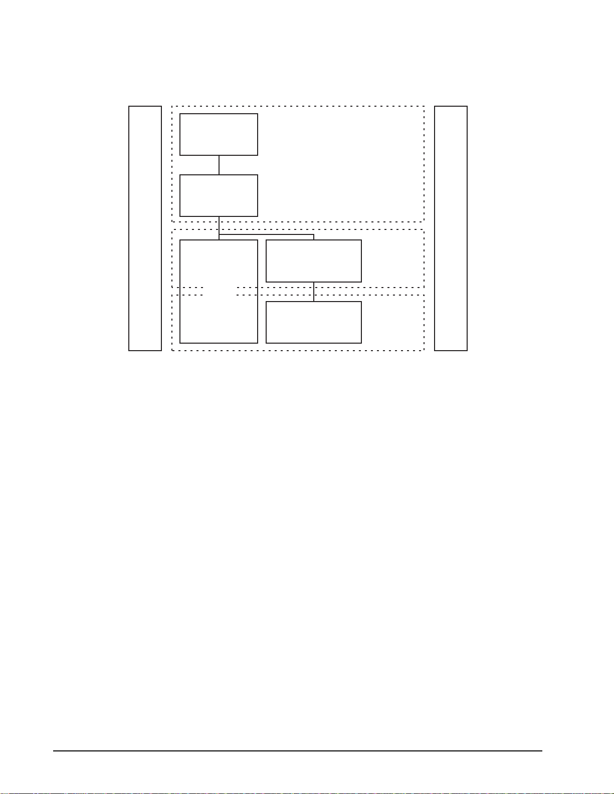
1.1.1 Scope of SCSI standards
Figure 1 uses a representative set of specifications to show the functional partitions and the relationships
among SCSI standards applicable to drives covered by this product manual.
SCSI Block
Commands (SBC)
Commands
SCSI Primary
Commands (SPC)
SCSI
Interlocked
Protocol
SCSI Architecture Model (SAM)
Figure 1. Functional scope of SCSI standards
and
SCSI
Parallel
Interface (SPI-3)
SCSI
Fibre Channel
Protocol (FCP)
Fibre Channel
Physical and Signaling
Interface (FC-PH)
Protocols
Common Access Method (CAM)
Interconnects
2 SCSI Interface Product Manual, Rev. C

The functional areas define the scope of each standard as follows:
• SCSI Architecture Mode l: Define s the SCSI sy stem s model , the functio nal partitioni ng of the SCSI standard
set and requirements applicable to all SCSI implementations and implementation standards.
• Commands: Implementation standards which define classes including a device model for each class. These
standards specify the r equired comm ands and beha vior that is comm on to all devic es or unique to a gi ven
class of devices and prescribe the rules to be followed by a SCSI initiator port when sending commands to a
device.
• Common Access Method: Implementation standard which defines a host architecture and set of services for
device access.
• Protocols: Implementation standards which define the rules for exchanging information so that different
SCSI devices can communicate.
• Interconnects: Implementation standards which define the electrical and signaling rules essential for devices
to interoperate over a given physical interconnect.
The diagram of Figure 1 shows how the standards listed below fit within each category . The standards included
in the diagram are meant to serve as examples and may not reflect the full set of standards currently in force.
1.1.2 Applicable standards
The following ANSI standa rds should be refe renced for more de tails about SCSI syste m standards of operation:
• SCSI Architecture Model-2 (SAM-2), T10/1157D
• SCSI Enclosure Services Command Set (SES), T10/1212D
• SCSI Block Commands (SBC-2), T10/1417-D
• SCSI Primary Commands-3 (SPC-3), T10/1416-D
• SCSI Enhanced Parallel Interface (EPI), T10/1143D
• SCSI Parallel Interface (SPI-4), T10/1365D
• SCSI Medium Changer Commands (SMC), T10/999D
• SCSI Controller Command Set-2 (SCC-2), T10/1225D
• SCSI Stream Device Command Set (SSC), T10/997D
• SCSI Enclosure Services (SES), T10/1212D
1.2 General interface description
This SCSI Interfac e Product Manual d escribes the Seag ate Technology, Inc. subset of th e SCSI ( Small Computer Systems Interface) as implemented on the Seagate-built drives. The interface is compatible with the
SCSI Interface Specifications listed in S ection 1.1.2 . The drives covered by this product ma nual are classi fied
as “Intelligent” peripherals.
The Seagate SCS I interface describe d herei n consists o f a 9 or 18 bit bidirectio nal data bus (includ es bits for
parity checking and enabli ng CRC p ro tec tio n), plus 9 con trol signals. The SCSI interfac e sup ports mul ti ple in itiators, disconne ct/reconnect, self-configu ring host so ftware, automatic features that relieve the host from the
necessity of know ing the ph ys i cal a rchi tec tur e of the target (log ic al bl ock addressing is us ed ), and some other
miscellaneous feat ures .
The SCSI physical inte rface uses either s ingle-ended drivers and receivers or low vol tage differential drivers
and receivers an d uses asynchronous or synchronous communication protocols. The bus i nterface transfer
rate for asynchronous or syn chronous is given in ind ividual drive ’s Product Manual , Volume 1. The bus protocol supports multiple i nitiators, disconnect /reconnect, additiona l messages plus 6-byte, 10- byte, 12-byte, 16byte and variable length Command Descriptor Blocks.
SCSI Interface Product Manual, Rev. C 3
Unless specified othe rwise in th e individual drive’s Product Manual, Volume 1, the drive is always a S CSI target port, and never a SCS I initiator port. For certain com man ds, whi ch may or may not be supported by a particular drive model, the drive must act as a S CSI initiator port, but does not othe rwise do so. For purposes of
this specification, “drive” may be substituted for the word “target” wherever “target” appears.
In the event of a conflict between this document and ANSI SCSI documents, the requirements of the ANSI documents shall apply.
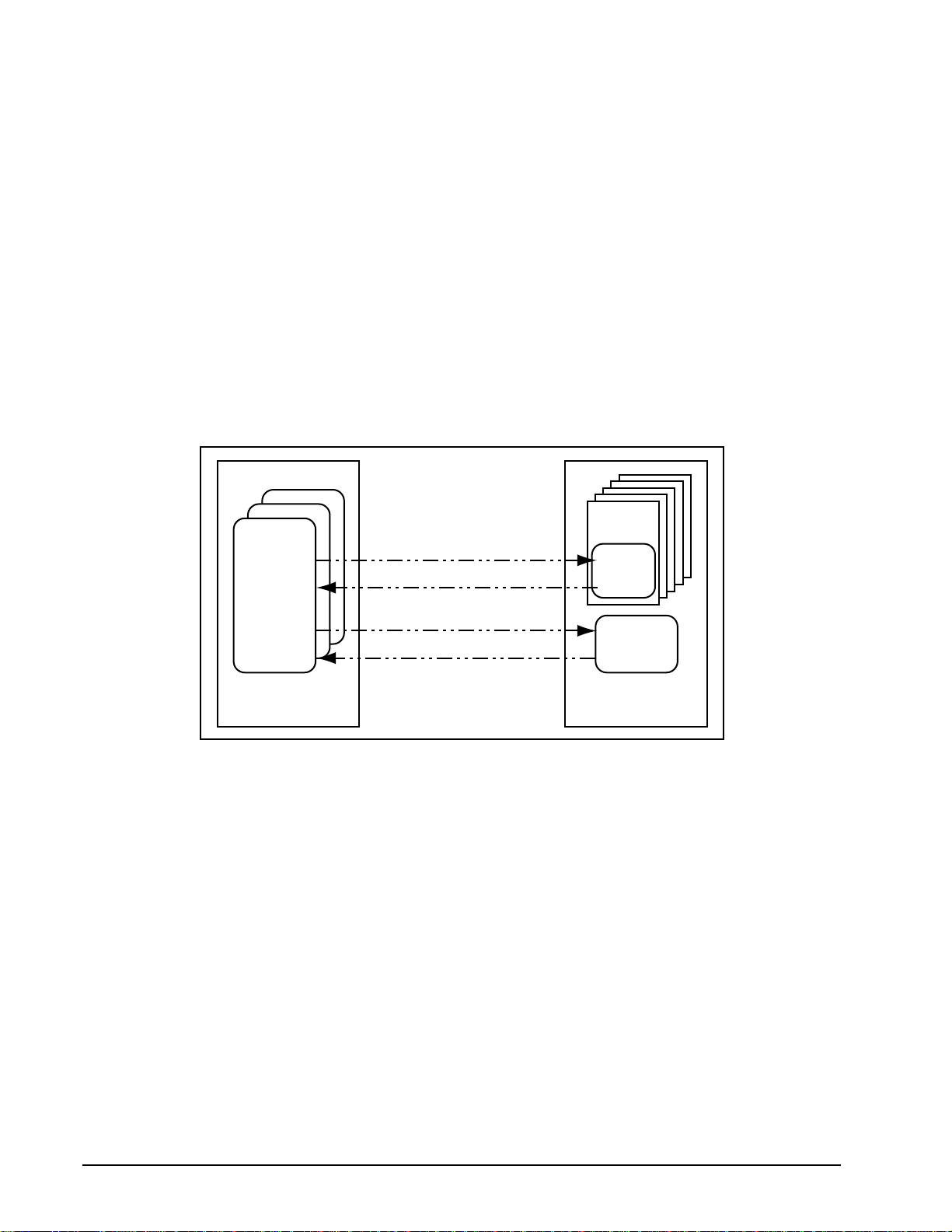
Note. In this revision, some new terminology is introduced as taken from the ANSI specifications. In many
instances, the broader scope terms such as “initiator” and “target” are not used, but rather the more
specific terms “initiator” and “target” appear. In Figure 2, it can be seen that several “initiators” from
a single initiato r may have one or mo re tasks in queue with se veral “targets” in a singl e target. A
drive could be a S CSI target port or it could be one of the targets as part of some larg er entity.
When reading the description, one needs to be able to put the drive of interest in the proper context
in terms of what is shown in Figure 2. For a proper understanding of the operation of the SCSI protocol, the terms in the SCSI architectural model as described in ANSI specification T10/1157D
(SAM-2) should be well understood before r eading operatio n descriptions in any SCSI document.
Although a Glossary of terms is provided herein, the definitions may not be adequate for some. The
SAM-2 specification gives a more detailed understanding of some of the new SCSI terminology
Logical
Unit
Application
Client
Device Service Request
Device Service Response
Device
Server
Task Management Request
Task Management Response
Initiator
Figure 2. SCSI client-server model
Task
Manager
Target
1.2.1 Glossary aborted command—A SCSI command that has been ended by aborting the task created to execute it. ACA—Auto Contingent Allegiance (see below). ACA command—A command performed by a task with the ACA attribute. See Section 4.4.2. initiator—An object that i s the source of SCS I commands. An o bject in this se nse is not a tangible piec e of
hardware, but may be a s ing le num er ic para mete r, such as a logic al un it n umb er, or a complex enti ty tha t per forms a set of operations or services on behalf of another object (see ANSI SAM-2, T10/1157D).
asynchronous event notification—A procedure used by targets to notify initiato rs of even ts that occur whe n
a pending task does not exist for that initiator.
asynchronous transfer—An information transfer that uses the REQ/ACK handshake with an offset of zero.
auto contingent allegiance—One of the conditions of a task set following the return of a CHECK CONDITION
status. See Section 4.4.2.
4 SCSI Interface Product Manual, Rev. C

blocked (task state)—The state of a task that is prevented from completing due to an ACA condition.
blocking boundary—A task set boundary deno ting a set of condi tions that in hibit tasks ou tside the bou nda ry
from entering the Enabled state.
byte—An 8-bit construct.
call—The act of invoking a procedure.
client-server—A relationship established between a pair of distributed objects where one (the client) requests
the other (the server) to perform some operation or unit of work on the client’s behalf (see ANSI standard
SAM-2, T10/1157D).
client—An object that requests a service from a server.
command—A request describing a unit of work to be performed by a target.
command descriptor block—A structure used to communicate a command from an initiator to a target. Com-
mand structures of 6, 10, 12, or 16 bytes are used, but a new v ariable length co mmand s truct ure has rec ently
been introduced.
completed command—A command that has ende d by retur ni ng a status and s ervi ce resp ons e of Task Complete or Linked Command Complete.
completed task—A task that has ended by r eturning a status and service r esponse of Task Complete. The
actual events comprising the Task Complete response are protocol specific.
confirmation—A response returned to an object, which signals the completion of a service request.
confirmed service—A service av ai lab le at th e p ro toc ol s er v ice interface, which req uires co nfi rm ati on of com-
pletion. The confirm ed s ervi ce consists of the request and co nfi rm ati on steps and optionally the indic atio n an d
response steps.
contingent allegiance—An optional condition of a task set following the return of a CHECK CONDITION status. A detailed definition of contingent allegiance may be found in Section 4.4.2.
control mode page—The mode page that identifies the sett ings of several target behavior s that may be of
interest to an initiat or or may b e changed by an initiator. The complete de finition of the Control mode page is
found in Section 8.13.9.
current task—A task that is in the process of sending messages, sending status, transferring data, or transferring command data to or from the initiator.
cyclic redundancy chec k (CRC)—An error detec ting code used to detect the validi ty of data that has been
transferred during the current data group.
data field—The portion of a data group that contains data bytes.
data group—A sequence of data bytes and the f our pCRC bytes during a DT D ATA IN PHASE or a DT DATA
OUT PHASE that starts at the first byte of the DT DATA phase or at the first byte after the last pCRC byte.
data group transfer—Parallel transfers that t ransfer d ata and pCRC i nform ation us ing only data gro ups. The
last four bytes of a data group transfer contain CRC information over the whole data group.
destination device—The SCSI device to which a service delivery transaction is addressed. See source
device.
target—An object within the logical unit which executes SCSI tasks according to the rules for task manage-
ment described in clause 7 of ANSI SAM-2 document, T10/1157D.
device service request—A request, submitted by an initiator, conveying a SCSI command to a target.
SCSI Interface Product Manual, Rev. C 5

device service response—The response returned to an initiator by a target on completion of a SCSI command.
differential—A signalling alternative that empl oys di fferential (tw o com pleme ntary signals ) drivers and rec eivers to improve signal-to-noise ratios and increase maximum cable lengths.
disconnect—The action that occurs when a SCSI devi c e releas es con tr ol of the SCS I bus, all owi ng it to go to
the BUS FREE PHASE.
domain—An I/O system consistin g of a set of SCSI dev ices tha t inter act with one anoth er by mean s of a service delivery subsystem.
dormant (task state)—The state of a task that is prevented from starting execution due to the presence of certain other tasks in the task set.
double transition (DT)—The latching of data on both the assertion edge and the negated edge of the REQ or
ACK signals.
driver—The circuitry used to control the state of the bus.
enabled (task state)—The state of a task th at m ay comp lete at any time. Alterna tiv el y, the state of a task that
is waiting to receive the next command in a series of linked commands.
ended command—A command that has completed or aborted.
exception condition—Any event that causes a SC SI d evice to e nter an auto co ntinge nt alle gian ce or c ontin-
gent allegiance condition.
faulted initiator—The initiator to which a Command Terminated or CHECK CONDITION status was returned.
faulted task set—A task set that contained a faulting task.
faulting command—A command that completed with a status of Check Condition or Command Terminated.
faulting task—A task that has completed with a status of Check Condition or Command Terminated.
function complete—A logical unit response indicating that a task management function has finished. The
actual events comprising this response are protocol specific.
hard reset—a SC SI target port respo nse to a reset event o r a S CSI target port Rese t in which the target per-
forms the operations described in Section 7.6.7.
implementation—The physical realization of an object.
implementation-specific—A requireme nt or feature tha t is define d in a SCSI s tandard but whose i mplemen-
tation may be specified by the system integrator or vendor.
implementation option—An option whose actualization within an imple mentation is at the discretion of the
implementor.
indication—The second step in a four-step confirmed service reply to a request.
information unit tr ansfer—Pa rallel tran sfers that transfe r data, status, commands, task attribut es, task man-
agement information, acrid, and nexus information using only SPI information units.
initial connection—The result of a physical connect. It exists from the assertion of the BSY signal in a
SELECTION PHASE until the next BUS FREE PHASE or the next QAS REQUEST message.
initiator—A SCSI device containing initiators which originate device service and task management requests to
be processed by a SCSI target port SCSI device.
interconnect—The electrical media (including connectors and passive loads) used to connect the TERM-
PWR, terminators, and SCSI devices in a SCSI bus.
6 SCSI Interface Product Manual, Rev. C

interconnect subsys tem —One or more physical in terc onne cts whi ch appear as a single path for the tra ns fer
of information between SCSI device s in a domai n.
intersymbol interference (ISI)—The effect of adjacent symbols on the symbol currently being received.
in transit—Information that has been sent to a remote object but not yet received.
I/O operation—An operation defin ed by an u nlink ed SCS I com mand, a seri es of li nked S CSI c ommand s or a
task management function.
I/O process—An I/O process consists of one initial connection or, if information units are enabled, the
establishment of a nexus, and a zero o r more physic al or l ogical r econne ction all per taining to a s ingle task or
a group of tasks. An I/O process beg ins with the es tabli shmen t of a nex us . If the SPI inform ati on un it trans fe rs
are disabled, an I/O pr ocess no rmally end s with a C ommand Com plete mes sage. If info rmation u nit transfe rs
are enabled, an I/O process ends with a SPI L_Q info rmati on un it wit h the ty pe fi el d set to status an d the Data
Length field set to zero.
I T nexus—A nexus that exists between a SCSI initiator port and a SCSI target port.
I T L nexus—A nexus that exists between a SCSI initiator port, a SCSI target port, and a logical unit. This rela-
tionship replaces the prior I T nexus.
I T L Q nexus—A nexus between a SCS I initiator por t, a SCSI target port, a logi cal unit, and a queue tag fol-
lowing the successful receipt of one of the queue tag message s. This relationship replaces the prior I T L
nexus.
iuCRC protection—The use of CRC to detect DT DATA PHASE data transmission errors during parallel transfers. Contains CRC information covering all bytes transmitted in a SPI information unit.
layer—A subdivision of the architecture constituted by subsystems of the same rank.
linked CDB—A CDB with the link bit in the control byte set to one.
linked command—One in a series of SCSI comman ds execu ted by a si ngle task, whic h coll ectiv ely make up
a discrete I/O operati on. In such a series, ea ch co mmand has the same task identifier, and all except t he last
have the link bit in the CDB control byte set to one.
logical connect—Establishes an I_T_L_Q nexus using SPI L_Q information units.
logical disconnect—Reduces the current I_T_L_Q nexus to an I_T nexus.
logical reconnect—Reestablishes an I_T_L_Q nexus from an I_T nexus using SPI L_Q information units.
logical unit—a SCSI target port-reside nt entity which implements a device model and exec utes SCSI com-
mands sent by an initiator.
logical unit number—A 64-bit identifier for a logical unit.
logical unit option—An option pertaining to a logical unit, whose actualization is at the discretion of the logical
unit implementor.
lower level protocol—A protocol used to carry the information representing upper level protocol transactions.
mandatory—The referenced item is required to claim compliance with a standard.
media information—Informatio n store d within a SCSI d evice whic h is n on-volatil e (retained through a po wer
cycle) and accessible to a SCSI initiator port through the execution of SCSI commands.
multidrop—A characteristic of the SCSI bu s that allo ws SCSI devices to be connecte d to the SCSI bu s with-
out disrupting the electrical path between the terminators.
multimode single-ended (MSE)—A signalling alternative for multimode SCSI devices that employs MSE driv-
ers and receivers to allow multimode SCSI devices to operate when SE SCSI devices are present on the bus.
SCSI Interface Product Manual, Rev. C 7

nexus—A relat ionship between a SCSI initia tor port and a SCSI target port, lo gical unit, or queue tag that
begins with an ini tia l co nne ction and ends with the completion of the associated I/O pr oces s. T hi s rel ati ons hi p
is formed as the result of a task.
object—An architectural abstraction or “container” that encapsulates data types, services, or other objects that
are related in some way.
odd parity—Odd logical parity, where the parity bit is dri ve n an d v erifi ed to b e th at v al ue that mak es th e nu mber of assertions o n the asso ciated data byte p lus the parity bit eq ual to an o dd num ber (1, 3, 5, 7, or 9). See
parity bit. If an even number of asserted bits are detected at the receiver, a parity error occurs.
paced transfer—Parallel transfers that transfer information using pacing.
pacing—Use of the ACK or REQ signal as a contin uously runni ng clock i n combinati on with the P 1 signal t o
indicate when data is valid.
packetized—A method of transferring information using SPI information units. See object.
pad field—The portion of a data group that contains pad information.
parallel protocol request—Messages use d to ne got iate a sy nchr on ous data trans fer agree men t, a wi de da ta
transfer agreement, and set the protocol options between two SCSI devices.
par i t y b i t —A bi t associ ated with a byte that is used to detect th e presence of an od d number of asser ted bits
within the byte. The parity bit is driven such that the number of logical ones in the byte plus the parity bit is odd.
pCRC field—The portion of a data group that contains pCRC information.
pCRC protection—The use of pCRC to detect DT DATA PHASE.
peer-to-peer protocol service—A service used by an upper level protocol implem entation to exchange infor -
mation with its peer.
peer entities—Entities within the same (protocol) layer.
pending task—A task that is not a current task.
physical interconnect—A single physical pathway for the transfer of informat ion between SCS I devices in a
domain.
physical reconnect—Th e act of resumi ng a nexus to continue a task. A S CSI target port i nitiates a phys ical
reconnect when conditions are appropriate for the physical bus to transfer data associated with a nexus
between a SCSI initiator port and a SCSI target port.
physical reconnection—The result of a physical reconn ec t that ex ists from the asserti on of the BS Y signal in
a SELECTION or RESEL ECTION PHASE. A physical reconnection e nds with the BUS FREE PHASE (see
Section 3.1.1) or a QAS REQUEST message (see Section 4.3.13).
port—Synonymous with “service delivery port.” A single attachment to a SCSI bus from a SCSI device.
procedure—An operation that can be invoked through an external calling interface.
protocol—The rules governing the conten t and exchange of informatio n passed between distributed obje cts
through the service delivery subsystem.
protocol option—An option whose definition within a SCSI protocol standard is discretionary.
protocol service confirmation—A signal fr om the lower level pro tocol service lay er notif ying the up per l ayer
that a protocol service request has completed.
protocol service indication—A signal from the lower level protocol service layer notifying the upper level that
a protocol transaction has occurred.
8 SCSI Interface Product Manual, Rev. C

protocol service request—A call to the lo wer le ve l protoc ol s er vic e l ay er to begin a protocol ser vi ce tran sa ction.
protocol service response—A reply from the upper level protocol layer in response to a protocol service indication.
quick arbitration and selection process (QAS)—Quicker than the normal arbitrati on and s electio n pro cess.
Implementation is optional for SCSI devices.
queue—The arrangement of tasks within a task set, usually according to the temporal order in which they were
created. See task set.
queue tag—The parameter associated with a task that uni que ly id enti fi es it f ro m ot her tagged tasks for a log ical unit from the same initiator.
receiver—A client or server that is the recipient of a service delivery transaction.
reference model—A standard model used to specif y sys tem requi remen ts in an i mplem entation- indepe ndent
manner.
request—A transaction invoking a service.
request-response transaction—An interaction between a pa ir of d istributed , cooper ating ob jects, co nsisting
of a request for service submitted to an object followed by a response conveying the result.
request-confirmation transaction—An interaction between a pair of cooperating objects, consisting of a
request for service submitted to an object followed by a response for the object confirming request completion.
reset event—A protocol-specific event which may trigger a hard reset response from a SCSI device as
described in Section 5.3.
response—A transaction conveying the result of a request.
SCSI application layer—The proto cols and procedures tha t implement or invoke S CSI commands and task
management functions by using services provided by a SCSI protocol layer.
SCSI device—A device that contains at le ast one SCSI port and the means to connec t its drivers and receiv-
ers to the bus.
SCSI device identifier—An address by which a SCSI device is referenced within a domain.
SCSI I/O system—An I/O system, cons isting of two or more SCSI devices, a SCSI i nterconnect a nd a SCSI
protocol, which collectively interact to perform SCSI I/O operations.
SCSI protocol layer—The protocol and services used by a SCSI application layer to transport data represent-
ing a SCSI application protocol transaction.
sender—A client or server that originates a service delivery transaction.
server—A SCSI object that performs a service on behalf of a client.
service—Any operation or function performed by a SCSI object, which can be invoked by other SCSI objects.
service delivery failure —Any non-recoverable error causing t he corruption or loss of one or more ser vice
delivery transactions while in transit.
service delivery po rt—A device-residen t interface used by the initiato r, target or task manager to ente r and
retrieve requests and responses from the service delivery subsystem. Synonymous with “port.”
service delivery subsy stem—That part of a SCSI I/ O system which transmits serv ice requests to a logical
unit or target and returns logical unit or target responses to a SCSI initiator port.
service delivery transaction—A request or response sent through the service delivery subsystem.
SCSI Interface Product Manual, Rev. C 9

signal—(n) A detectable asynchro nous event possibly accompanied by descriptive data and parameters. (v)
The act of generating such an event.
single transition (ST)—The latching of data only on the assertion edge of the REQ or ACK signals.
source device—The SCSI device from which a service delivery transaction originates. See destination devic e.
SPI information unit—Data structures that encapsulate data, status, command, task attributes , iuCRC, and
nexus information into various formats.
SPI L_Q information unit—The SPI L_Q in for ma tio n unit (see Section 6.2. 2, tables 48 and 49) contains L_Q
nexus (Logical unit—Q tag relationship) information for the information unit that follows, the type of information
unit that follows, and the length of information unit that follows. A SPI L_Q information unit shall precede all SPI
command information units, SPI multiple command in formation units, SPI data information u nits, SPI status
information units, and the first of an uninterrupted sequence of SPI data stream information units.
subsystem—An element in a hierarchically part itioned system which i nteracts directly only wi th elements in
the next higher division or the next lower division of that system.
suspended information—Information stored within a logical unit that is not available to any pending tasks.
target—A SCSI device which receives SCSI com mands and directs such command s to one or more logical
units for execution.
task—An object withi n the logical unit representing the wor k associated with a command or group of lin ked
commands. A task consists of one initial connection and zero or more physical or logical reconnections, all pertaining to the task.
task abort event—An event or condition indic ating that the task has been aborted by means of a task m anagement function.
task address—a SCSI initiator port iden tifies a task to a SCSI target port usi ng a Task Addres s. The Task
Address object repr esen ts either a Tagged Task Address or an Untagged Task Address without regard for the
tagged or untagged nature o f the Task. A Tagged Task Address is composed of a Log ical Unit Ide ntifie r and a
Tag. An Untagged Task Address is composed of a Logical Unit Identifier.
task completion event—An event or condition indicating that the task has end ed with a ser vice response o f
Task Complete.
task ended event—An event or condition indicating that the task has completed or aborted.
task management function—A t ask manager service which can be invoked by an initiator to affect the execu-
tion of one or more tasks.
task management request—A request submitted by an initiator, invoking a task management fun ction to be
executed by a task manager.
task management response—The response returned to an initia tor by a task manager on comple tion of a
task management request.
task manager—A server within the target which executes task management functions.
task set—A group of tasks within a SCSI target port devi ce, whose interac tion is dependent on the queuing
and auto contingent allegiance rules of Section 7.6.1.
task slot—Resources within the logical unit that may be used to contain a task.
task tags—A Tag is a field containing up to 64 bits that is a component of a Tagged Task Identifier. A SCSI ini-
tiator port assigns tag values in each Tagged Task Identifier in a way that ensures that the identifier uniqueness
requirements stated in ANSI SAM-2, T10/1157D, Section 4.9, are met.
10 SCSI Interface Product Manual, Rev. C

third-party command—A SCSI command whic h re quire s a l ogi ca l uni t wit hin the target dev ice to as su me th e
initiator role and send a SCSI command to a SCSI target port device.
transaction—A cooperative interaction between two objects, involving the exchange of information or the execution of some service by one object on behalf of the other.
transfer period—The negotiated time between edges of RE Q or ACK that latch data. For ST, the transfer
period is measured from assertion edge of the REQ or ACK signal to the next assertion edge of the signal. For
DT, the transfer period is measured from a transition edge of the REQ or ACK signal to the next transition edge
of the signal.
unconfirmed protocol service—A service available at the protocol service interface, which does not result in
a completion confirmation.
unlinked command—A SCSI command having the link bit set to zero in the CDB control byte.
upper level protocol—An application-specif ic protocol execute d through services provided by a lower level
protocol.
1.2.2 Keywords
Several keywords are used to differentiate between different levels of requirements and optionality, as follows:
vendor-specific—Specification of the referenced item is determined by the device vendor.
protocol-specific—Implementation of the referenced item is de fined by a SCSI protocol standard (se e Sec-
tion 1.1.1.)
expected—A keyword used to describe the behavior of the models specified by this standard.
invalid—A keyword us ed to desc ribe an ille gal or u nsupp orted bit, by te, word, field , or c ode v alue. Receipt o f
an invalid bit, byte, word, field, or code value shall be reported as an error.
mandatory—A keyword indicating items required to be implemented as defined by this standard.
may—A keyword that indicates flexibility of choice with no implied preference (equivalent to “may or may not”).
may not—Keywords that indi cates flexibilit y of choice with no i mplied preference (equivalent to “ may or may
not”).
obsolete—A keyword indicating items that were defined in prior SCSI standard s but ha ve be en remo ve d f rom
this standard.
option, optional—Keywords that describe features which are not required to be implemented by this stan-
dard. However, if any optional feature defined by the standard is implemented, it shall be implemented as
defined by the standard.
reserved—A key word referring to bits, bytes, words, fields, and code values that are set aside for future standardization. Their us e and interpretation may b e specified by fu ture extensions to this or other standards. A
reserved bit, byte, word, or field sh all be s et to zero, or in acco rdanc e with a fu ture exten sion to this standard .
Recipients are not required to check rese rved bits, bytes , word s, or fiel ds for ze ro val ues. Rece ip t of reser ved
code values in defined fields shall be treated as an error.
shall—A keyword i ndicating a m andatory re quirement. De signers a re required to impleme nt all such mandatory requirements to ensure interoperability with other standard conformant products.
should—A keyword indicating flexibility of choice with a strongly preferred alternative. Equivalent to the
phrase “it is recommended.”
SCSI Interface Product Manual, Rev. C 11

1.3 Physical interface characteristics
The physical interface characteristics (cables, connectors, ele ctrical descriptions, termination requirements,
etc.) for the drives cover ed by this Interfac e Manual are found in each indivi dual drive’s Product Manual, Volume 1, since these features are not the same for all drives.
12 SCSI Interface Product Manual, Rev. C

1.4 Summary of SCSI commands and messages
Following is an a lphabetical table listing th e SCSI commands desc ribed in this manual. Details are given in
Section 8.0.
Command name Hex code Device type Page number
CHANGE DEFINITION 40 All 160
COMP ARE 39 All 160
COPY 18 All 160
COPY AND VERIFY 3A All 160
FORMAT UNIT 04 Direct access 161
INQUIRY 12 All 170
LOCK-UNLOCK CACHE (10) 36 Direct access 197
LOCK-UNLOCK CACHE (16) 92 Direct access 198
LOG SELECT 4C All 200
LOG SENSE 4D All 203
MODE SELECT (6) 15 Direct access 227
MODE SELECT (10) 55 Direct access 232
MODE SENSE (6) 1A Direct access 235
MODE SENSE (10) 5A Direct access 281
MOVE MEDIUM A7 284
PERSISTENT RESERVE IN 5E Direct access 285
PERSISTENT RESERVE OUT 5F Direct access 292
PREFETCH (10) 34 Direct access 297
PREFETCH (16) 90 Direct access 299
PREVENT/ALLOW MEDIUM REMOVAL 1E Direct access 300
READ (6) 08 Direct access 301
READ (10) 28 Direct access 303
READ (12) A8 Direct access 305
READ (16) 88 Direct access 307
READ BUFFER 3C All 309
READ CAPACITY (10) 25 Direct access 313
READ CAPACITY (16) 9E Direct access 315
READ DEFECT DATA (10) 37 Direct access 317
READ DEFECT DATA (12) B7 Direct access 319
READ ELEMENT STATUS B4 Direct access 321
REASSIGN BLOCKS 07 Direct access 324
RECEIVE DIAGNOSTIC RESULTS 1C All 326
RELEASE (6) 17 Direct access 330
RELEASE (10) 57 Direct access 330
REPORT DEVICE IDENTIFIER A3 All 331
REPORT LUNS A0 Direct access 333
REQUEST SENSE 03 All 336
RESERVE (6) 16 Direct access 348
RESERVE (10) 56 Direct access 348
REZERO UNIT 01 Direct access 348
SEARCH DATA EQUAL 31 Direct access 348
SEARCH DATA HIGH 30 Direct access 348
SEARCH DATA LOW 32 Direct access 348
SEEK 0B Direct access 348
SEEK EXTENDED 2B Direct access 349
SEND DIAGNOSTIC 1D All 350
SET DEVICE IDENTIFIER A4 All 354
SET LIMITS 33 Direct access 355
START/STOP UNIT 1B Direct access 356
SYNCHRONIZE CACHE (10) 35 Direct access 357
SCSI Interface Product Manual, Rev. C 13

Command name Hex code Device type Page number
SYNCHRONIZE CACHE (16) 91 Direct access 358
TEST UNIT READY 00 All 360
VERIFY (10) 2F Direct access 361
VERIFY (12) AF Direct access 363
VERIFY (16) 8F Direct access 365
WRITE (6) 0A Direct access 367
WRITE (10) 2A Direct access 369
WRITE (12) AA Direct access 371
WRITE (16) 8A Direct access 373
WRITE AND VERIFY (10) 2E Direct access 375
WRITE AND VERIFY (12) AE Direct access 377
WRITE AND VERIFY (16) 8E Direct access 379
WRITE BUFFER 3B All 381
WRITE LONG 3F Direct access 386
WRITE SAME (10) 41 Direct access 387
WRITE SAME (16) 93 Direct access 388
XD READ (10) 52 Direct access 390
XD READ (32) 7F Direct access 391
XD WRITE (10) 50 Direct access 393
XD WRITE (32) 7F D irec t acces s 394
XD WRITEREAD (10) 53 Direct access 396
XD WRITEREAD (32) 7F Direct access 397
XP WRITE (10) 51 Direct access 399
XP WRITE (32) 7F Direct access 400
14 SCSI Interface Product Manual, Rev. C

Following is an alphabeti cal summary of the SCSI messages d escribed in this manual. Details are given i n
Section 4.
Message Name Hex Code Page number
ABORT TASK 06 110
CLEAR QUEUE 0E 111
DISCONNECT 04 91
EXTENDED MESSAGE 01 88
IDENTIFY 80-FF 91
IGNORE WIDE RESIDUE 23 92
INITIATE RECOVERY 0F Not described in this manual
INITIATOR DETECTED ERROR 05 93
MESSAGE PARITY ERROR 09 93
MESSAGE REJECT 07 93
MODIFY DATA POINTER 01, 05, 00 94 (extended message)
NO OPERATION 08 95
PARALLEL PROTOCOL REQUEST 01, 06, 04 96
QAS REQUEST 55 100
RELEASE RECOVERY 10 Not described in this manual
RESTORE POINTERS 03 100
SAVE DATA POINTERS 02 100
SYNCHRONOUS DATA TRANSFER REQUEST 01, 03, 01 101 (extended message)
TASK ATTRIBUTE MESSAGES 107
ACA (AUTO CONTINGENT
24 108
ALLEGIANCE)
HEAD OF QUEUE TAG 21 109
LINKED COMMAND COMPLETE 0A 93
ORDERED QUEUE TAG 22 109
SIMPLE QUEUE TAG 20 109
TASK COMPLETE 00 104
TASK MANAGEMENT MESSAGES 110
ABORT TASK 00 110
ABORT TASK SET 06 111
CLEAR ACA 16 111
CLEAR TASK SET 0E 111
LOGICAL UNIT RESET 17 111
TARGET RESET 0C 111
WIDE DATA TRANSFER REQUEST 01, 03 104 (extended message)
SCSI Interface Product Manual, Rev. C 15

16 SCSI Interface Product Manual, Rev. C

2.0 SCSI bus
This manual discusses only the “logical” and timing characteristics of the SCSI system and interface. A general
description of the SCSI bus physical characteristics (voltages, connector configurations, pinouts, etc.) are
given in the indivi dua l dr iv e’s Prod uc t M anua l, Volume 1, in the “ In ter fac e r eq ui rem en ts” sec ti on, whic h co ve rs
the interface requ ireme nts and S CSI fe ature s su pported by the dri ve de scribe d in the parti cular Prod uct M anual being referenced. For all of the physical details of the SCSI interface, cons ult the ANSI standards referenced in Section 1.1.2.
Communication on the SCSI Bu s is al lowed between only two SCSI devi c es at a time . Sea gate dri ves s upp or t
systems with a maximum of 16 SCSI devices including the host computer(s) connected to the SCSI bus. Each
SCSI device has a SCSI ID bit assigned as shown in Table 1. The SCSI ID is assigned by installing 0-3 jumper
plugs onto a conne ctor in a binary co ded conf iguration d uring sys tem confi guratio n. Some dri ve model s have
an interface that incl udes the SCSI bus ID lines, so that the host can set the drive ID over the interface ( see
individual drive’s Product Manual, Volume 1, “Option/configuration headers” section).
When two SCSI devices communicate on the SCSI Bus, one acts as a SCSI initiator port and the other acts as
a SCSI target port. Th e initiator (typically a host compu ter) origin ates an I/O process and the target per forms
whatever operations/tasks ar e called for by the I/O proc ess. Devic es arbitrate to get contr ol of the bus t o perform whatever communications are required by the current I/O process. As part of the arbitration process,
devices on the SCSI bus assert their bus ID (one of the DB lines as shown in Table 1). The arbitration process
is discussed in more detail later. Devices sup ported by this interface spec ification alw ays operate a s targets,
unless otherwise s pecified (i.e., if certain commands are supported) in the individ ual drive’s Product Manual,
Volume 1.
SCSI Interface Product Manual, Rev. C 17

Table 1: SCSI IDs and associated SCSI bus arbitration priorities
SCSI ID/DB
line asserted
0 / DB0 #8
1 / DB1 #7
2 / DB2 #6
3 / DB3 #5
4 / DB4 #4
5 / DB5 #3
6 / DB6 #2
7 / DB7 #1 (highest)
8 / DB8 #16 (lowest)
9 / DB9 #15
10 / DB10 #14
11 / DB11 #13
12 / DB12 #12
13 / DB13 #11
14 / DB14 #10
SCSI bus
arbitration priority
15 / DB15 #9
The Host Adapter/Initiator must be identified by one of the 16 SCSI Device IDs (usually 7, which is highest arbitration priority). Make sure that none of the devices on the SCSI bus have duplicate IDs.
Certain SCSI bus functions are assigned to the initiator and certain SCSI bus functions are assigned to the target. The initiator will select a particular target. The target will request the transfer of Command, Data, Status, or
other information on the data bus.
Under SCSI-2 protocol, infor mation transfers on the data bus are inter locked and follow a defined REQ/ACK
Handshake protocol. One byte of information will be transferred with each handshake. Synchronous data
transfers do not require a one-for-one interlocking o f RE Q/ ACK s ignals , b ut the total number of REQ pulses in
a particular data transfer ev ent must equal the total number of A CK pulses. The synchronous data transfer
option is describe d in Par agraphs 3.1.5.2 and 3.5. 3.2 of th e Ultr a2 SCS I Interfac e Pro duct Manua l, Volume 2,
part number 77738479.
This Ultra160/Ultra320 SC S I Inte rf ace Prod uc t Man ual , Volume 2, discusse s S CSI- 3 p ro tocol (no w ca ll ed on ly
“SCSI”). There are now different ways of latc hing data from the REQ and ACK si gnals , depend ing on whet her
ST DATA phases, DT DATA phases, or paced transfers are being used for information transfers. This is
described in Section 2.1.2.
The drive supports single initiator, single target; single initiator, multiple target; multiple initiator, single target; or
multiple ini tiator, multiple target bus configurations.
18 SCSI Interface Product Manual, Rev. C

2.1 SCSI bus signals overview
Information transfer on the SCSI bu s is all owed betw een only two SC SI devi ces at an y give n time ex cept dur ing MESSAGE IN P HASE when QAS is enabled. A ll SCSI devices that have Q AS enabled are required to
monitor messages during a MESSAGE IN PHASE for a QAS REQUEST MESSAGE. The maximum number of
SCSI devices is determined by the width of the data path implemented. T h e S CS I de vi ce s may b e a ny c omb ination of SCSI initiat or ports (commonl y called “initi ators”) and SC SI target ports (commonly called “targets”),
provided there is at least one of each.
Each SCSI device has a SCSI address and a corresponding SCSI ID bit assigned to it. When two SCSI
devices communicat e on t he SCSI bus, one acts as the initiator a nd the ot her acts a s the target. The initia tor
originates an I/O process and the target receives the I/O process.
Some drive models ha ve a single 80- pin I/O connect or that contains additional inter face lines that c arry drive
configuration select signals. These are peculiar to certain drives and are not SCSI standard signals. These are
described in the individual drive’s product manual, Volume 1.
The 28 SCSI standard signals are described as follows:
BSY (Busy)—An “OR-tied” signal to indicate the bus is being used.
SEL (Select) —A n “OR- tied” s ignal u se d b y a S CS I i nitiator port to select a SCS I tar get por t, or b y a S CS I tar-
get port to reselect a SCSI initiator port.
RST (Reset)—An “OR-tied” signal that indicates the bus reset condition (see Section 5.2).
C/D (Control/Data)—A signal sourced by a SCSI target port that indicates whether CONTROL or DATA
PHASE information is on the data bus. Assertion indicates Control (i.e., COMMAND, STATUS, and MESSAGE
phases).
I/O (Input/Output)—A signal sourced by a SCSI target p ort to con trol the dir ection of da ta movement on the
Data Bus with respect to a S CSI initiator p ort. Asserti on indicates in put to the initi ator. This signal also distin guishes between SELECTION and RESELECTION phases.
MSG (Message)—A signal sourced by a SCSI target port during the MESSAGE PHASE.
REQ (Request)—A signal sourced by a SCSI target port to indicate a request for an information transfer on the
SCSI bus.
ACK (Acknowledge)—A signal sourced by a SCSI initiator port to r espond with an acknowledgment o f an
information transfer on the SCSI bus.
ATN (Attention)—A signal sourced by a SCSI initiator port to indicate the Attention condition.
DIFFSENS (Differential Sense)/Multimode—SE or LVD alternative— “LW” and “LC” models have I/O cir-
cuits that can operate e ither in single-ended ( SE) or low voltage differentia l (LVD) mode. Whe n the interface
DIFFSENS line is between 0 V and 0.6 V, the drive interface circuits operate single-ended. When DIFFSENS is
between +0.7 V and +1.9 V, the drive interface circuits operate low voltage differential. This arrangement is not
intended to allow dynamic ally changing tr ansmission modes , but rather to prevent in compatible devic es from
attempting to interoperate. Drives must operate only in the mode for which the installation and interface cabling
is designed. Multi mode I/O circuits us ed by “LW” and “LC” devices do not op erate at high voltage differential
levels and should never be expos ed to hig h volta ge different ial envi ronme nts unless th e co mmand m ode vo ltages in the environmen t are con tr oll ed to safe lev els for sin gl e-ended and low voltage differential devi ce s ( se e
the ANSI SPI-4 specification). High Voltage Differential (HVD) is now an obsolete ANSI standard.
P_CRCA (Parity/CRC Available)—A signal identifying either parity or CRC available based on bus phase and
negotiated settings.
SCSI Interface Product Manual, Rev. C 19

During the SE LE C TIO N PHA SE , R E SE LE CT IO N PH A SE, ST DATA PH A SE, CO MMAN D P HAS E , M ES SAG E
PHASE, and STATUS PHASE, this signal is referred to as DB(P_CRCA) and is sourced by the SCSI device
port driving the Data Bus. The DB(P_CRCA) signal is associated with the DB(7-0) signals and is used to detect
the presence of an odd numb er of bi t er rors within the byte. The DB(P_CRC A) bi t is driv en s uch tha t the n umber of logical ones in the byte plus the parity bit is odd.
Data group transfers are enabled (see Section 4.3.12) when this signal is referred to as P_CRCA and is
sourced by the target to control whet her a data group fiel d is a pad field, pCRC field, or data field (see Section
2.11.1). When asserted, the data group field shall be pad or pCRC fields that shall not be transferred to the initiator. When negated, the data group field shall be a data field that shall be transferred to the initiator.
During DT DATA phases when information unit transfers are enabled, this signal is referred to as P_CRCA and
sourced by the SCSI target. Depending on th e negotiated cond ition of read streami ng and write flo w control,
the SCSI initiator and target usage for P_C RCA is different. When information unit transfer s are enable d, the
SCSI target and initiator shall use the P_CRCA signal as indicated in Table 2.
Table 2: P_CRC signal usage requirements
SCSI initiator
Write flow
control
Read
streaming DT Data phase
response to
P_CRCA SCSI target usage of P_CRCA
Disabled Disabled All Ignore Continuously negated.
Enabled Disabled DT DATA IN Ignore Continuously negated.
DT DATA OUT Monitor Asserts to indicate when the current SPI data
stream information unit is the last SPI data
stream information unit of the current write
stream.
Disabled Enabled DT DATA IN Monitor Asserts to indicate when the current SPI data
stream information unit is the last SPI data
stream information unit of the current re ad
stream.
DT DATA OUT Ignore Continuously negated.
Enabled Enabled DT DATA IN Monitor Asserts to indicate when the current SPI data
stream information unit is the last SPI data
stream information unit of the current re ad
stream.
DT DATA OUT Monitor Asserts to indicate when the current SPI data
stream information unit is the last SPI data
stream information unit of the current re ad
stream.
P1 (Parity 1)—A signal normally sourced by the SCSI device driving the Data Bus. The P1 signal is associated
with the DB(15–8) signals and is used to detect the presence of an odd number of bit errors within the byte The
P1 bit is driven such that the number of logical ones in the byte plus the P1 bit is odd.
During the SELECTION PHASE, ST DATA PHASE with transfer length set for 8-bit transfers, COMMAND
PHASE, MESSAGE PHASE, and STATUS phase, the P1 signal shall not be driven by any SCSI device.
When data group transfers are enabled (see Sec tion 4.3.12), the P1 signal shall be con tinuously negat ed by
the SCSI devic e driv ing th e DB( 15-0) signal s and sha ll be igno red by the SCSI device rec eiving the DB (15-0)
signals during DT DATA phases.
When information unit trans fers are e nabled , the P1 si gnal shall be co ntinuously negated b y the SCS I devic e
driving the DB(15-0) signals and shall be ignored by the SCSI device receiving the DB(15-0) signals during DT
DA TA phases.
20 SCSI Interface Product Manual, Rev. C

DB(7–0) (8-bit data bus)—Each data bit that forms the 8-bit data bus. Bit significance an d prior ity dur ing arbitration are shown in Table 1.
DB(15–0) (16-bit data bus)—16 data bit signals that form the 16-bit Data Bus. Bit significance and priority during arbitration are shown in Table 1.
Greater detail on each of the SCSI bus signals is found in the following sections.
2.1.1 Drive select
For SCSI ID se lection, install drive select jumpers as s hown in config uration selec tion figure i n the individual
drive’s Product Manual , Volume 1. Refer to the “Physical interface” se ction of the individual dr ive’s Product
Manual for the location of the drive select header. Drives using the 8-bit data interface can have one of eight ID
bits selected by installing 0 through 2 (3) jump ers in a binary coded configuration on the drive select he ader.
Drives using the 16-bit data interfa ce can have one of 16 ID bits selecte d by installing 0 through 3 (4) ju mpers
in a binary coded configurat ion on the drive select heade r. “LC” model drives (80-pin direct connect I/O connector) can be assigned their bus ID over the SCSI interface.
2.1.2 Signal values
Signals may ass ume true or false values. There are two methods of driving th ese signa ls. In both cases, the
signal shall be actively driven true, or asserted. In the case of OR-tied drivers, the driver does not drive the signal to the false state, rather the bias circuitry of the bus terminators pulls the signal false whenever it is
released by the drivers at every SCSI device. If any dri ver is asserted, then the sig nal is true. In the case of
non-OR-tied drivers, the sign al may be negated. Neg ated means tha t the signal may be acti vely driven fal se,
or may be simply released (in which case the bias circuitry pulls it false), at the option of the implementor.
2.2 Signal states
2.2.1 SE signals
Signals may be in a true (asserted) or false (negated) state. Signals that are asserted are actively driven to the
true state. Signals that are negated may either be ac tively driven to the false state o r released to the false
state. A signal that is released g oes to the false stat e because the bi as of the termin ator pull s the sign al false .
OR-tied signals shall not be actively driven false.
Note. The advantage of actively negating signals false during information transfer is that the noise margin
is higher than if the signal is simpl y released. This facilitates reliable data transfer at high trans fer
rates.
Bits of the data bus are defined as one when the signal is true and defined as zero when the signal is false.
2.2.2 LVD signals
Figure 3 defines the voltage and current d efinitions. A signal that is relea sed goes to the false s tate because
the bias of the terminator pulls the signal false.
SCSI Interface Product Manual, Rev. C 21

I
)
–
– SIGNAL
V
s
V
–
V
+
+ SIGNAL
I
+
– TRANSCEIVER
Figure 3. Voltage and current definitions
Figure 4 defines the signaling sense of the voltages appearing on the – signal and + signal lines as follows:
a. The – signal terminal of the driver shal l be negative with respect to the + signal terminal for an asserted
state.
b. The – signal terminal of the driver shall be positive with respect to the + signal terminal for a negated state.
LOGICAL 1
(ASSERTED)
(TRUE)
+
V
–
V
+
–V
–
V
DIFFERENTIAL BUS VOLTAGE
Figure 4. LVD Signaling sense
Note. For a description of V
BIAS
2.3 OR-tied signals
LOGICAL 0
(NEGATED)
(FALSE)
VCM=(V++V–)/2 V
LOGICAL 1
(ASSERTED)
(TRUE)
V
V
CM
N
BIAS
0V (OFF
V
A
TIME
see Section 7.3.1 of ANSI specification (SPI-4), T10/1365D.
The BSY, SEL, and RST signals shall be OR-tied. BSY and RST signals may be simultaneously driven true by
several SCSI devices. No signa ls other than BSY, SEL, RST, DB(P_CRCA), and DB(P1) are simul taneously
driven by two or more SCSI devices. DB(P_CRCA) and DB(P1) shall not be driven fal se durin g the ARBITRATION PHASE but may be driven false in other phases .
22 SCSI Interface Product Manual, Rev. C

2.4 Signal sources
Tabl e 3 indicates the type of SC SI device allowed to sourc e each signal. No attemp t is made to show if the
source is driving asserte d, driving negated, or i s release d. All SC SI device dr ivers th at are not active sou rces
shall be in the high-impedance state. The RST signal may be asserted by any SCSI device at any time.
Table 3: Sign al sources
SCSI bus phase BSY SEL
16 data bit (P) cable
8 data bit (A) cable
C/D, I/O,
MSG, REQ ACK, ATN DB(7-0) P_CRCA
DB(15-8),
DB(P1)
BUS FREE None None None None None None None
ARBITRATION
All Win None Non e S ID S ID S ID
(NORMAL)
QAS ARBITRATION PT Win None None S ID S ID S ID
SELECTION I & T Init None Init Init Init Init
RESELECTION I & T Targ Targ Init Targ Targ Targ
COMMAND Targ None Targ Init Init Init None
ST DATA IN Targ None Targ Init Targ Targ Targ
ST DATA OUT Targ None Targ Init Init Init Init
DT DATA IN Targ None Targ Init Targ Targ Targ
DT DATA OUT Targ None Targ Init Init Targ Init
STATUS Targ None Targ Init Targ Targ None
MESSAGE IN Targ None Targ Init Targ Targ None
MESSAGE OUT Targ None Targ Init Init Init None
Table abbreviations are defined as follows:
All: The signal shall be driven by all SCSI devices that are actively arbitrating.
S ID: A unique data bit (the SCSI ID) shall be driven by each SCSI device that is actively arbitrating; the other
data bits shall be released (i.e., not drive n) by this SCSI device. The P_CRCA and DB(P1) bit(s) may
be released or driven to the true state, but shall not be driven to the false state during this phase.
I&T: The signal shall be driven by the initi ator, target, or both, as specified in the SELECTION P HASE and
RESELECTION PHASE.
Init: If driven, this signal shall be driven only by the active initiator.
None: The signal shall be released; th at is , no t driv en by an y S CSI de vi c e. T he bias ci rcui tr y o f the bu s te rm i-
nators pulls the signal to the false state.
Win: The signal shall be driven by the one SCSI device that wins arbitration.
Targ: If the signal is driven, it shall be driven only by the active target.
PT: Target that initiated the QAS arbitration.
SCSI Interface Product Manual, Rev. C 23

2.5 SCSI bus timing
Unless otherwise i ndicated, the delay time me asurements for e ach SCSI device, define d in paragraph s 2.5.1
through 2.5.58 shall be ca lc ulated from signal conditions ex isting at that SCSI device’s own SCSI bus co nnection. Thus, these measureme nts (except skew delay) can be made without consideri ng delays in the cable.
Refer to the tables below for the actual timing values for these delays.
Table 4: SCSI bus control timing values
Timing
Timing description Reference Type
Arbitration delay Section 2.5.1 minimum 2.4 µs
Bus clear delay Section 2.5.4 maximum 800 ns
Bus free delay Section 2.5.5 minimum 800 ns
Bus set delay Section 2.5.6 maximum 1.6 µs
Bus settle delay Section 2.5.7 minimum 400 ns
Cable skew [1] Section 2.5.8 maximum 4 ns
Data release delay Section 2.5.20 maximum 400 ns
DIFFSENS voltage filter time Section 2.5.21 minimum 100 ms
Physical disconnection delay Section 2.5.22 minimum 200 µs
Power on to selection [1] Section 2.5.23 maximum 10 s
QAS arbitration delay Section 2.5.24 minimum 1000 ns
QAS assertion delay Section 2.5.25 maximum 200 ns
QAS release delay Section 2.5.26 maximum 200 ns
QAS non-data phase REQ(ACK) period Section 2.5.27 minimum 50 ns
Reset delay Section 2.5.40 minimum 200 ns
Reset hold time Section 2.5.41 minimum 25 µs
Reset to selection [2] Section 2.5.42 maximum 250 ms
Selection abort time Section 2.5.44 maximum 200 µs
Selection time-out delay [2] Section 2.5.45 minimum 250 ms
System deskew delay Section 2.5.49 minimum 45 ns
value
[1] Cable skew is mea sured at each SCSI device c onnection wi th the transmitt ed skew sub tracted from th e
received skew.
[2] This is a recommended time. It is not mandatory.
24 SCSI Interface Product Manual, Rev. C

Table 5: SCSI bus data and information phase ST timing values
Timing values for negotiated transfer rate [1]
Timing description Reference Type
Asynch Fast-5 Fast-10 Fast-20 Fast-40
ATN transmit setup time Section 2.5.2 min 90 ns 33 ns 33 ns 21.5 ns 19.25 ns
ATN receive setup time Section 2.5.3 min 45 ns 17 ns 17 n s 8.5 ns 6.75 ns
Cable skew [2] Section 2.5.8 max 4 ns 4 ns 4 ns 3 ns 2.5 ns
Receive assertion period [3] Section 2.5.28 min N/A 70 ns 22 ns 11 ns 6.5 ns
Receive hold time [3] [4] Section 2.5.29 min N/A 25 ns 25 ns 11.5 ns 4.75 ns
Receive negation period [3] Section 2.5.32 min N/A 70 ns 22 ns 11 ns 6.5 ns
Receive setup time [3] [4] Section 2.5.33 min N/A 15 ns 15 ns 6.5 ns 4.75 ns
Receive REQ(ACK) period tolerance Section 2.5.34 min N/A 1.1 ns 1.1 ns 1.1 ns 1.1 ns
Signal timing skew Section 2.5.46 max 8 ns 8 ns 8 ns 5 ns 4.5 ns
REQ(ACK) period Section 2.5.39 nom N/A 200 ns 100 ns 50 ns 25 ns
Transmit assertion period [2] Section 2.5.53 min N/A 80 ns 30 ns 15 ns 8 ns
Transmit hold time [3] [4] Section 2.5.54 min N/A 53 ns 33 ns 16.5 ns 9.25 ns
Transmit negation period [3] Section 2.5.56 min N/A 80 ns 30 ns 15 ns 8 ns
Transmit setup time [3] [4] Section 2.5.57 min N/A 23 ns 23 ns 11.5 ns 9.25 ns
Transmit REQ(ACK) period tolerance Section 2.5.58 max N/A 1 ns 1 ns 1 ns 1 ns
[1] SCSI bus tim ing values specifie d by the maximum transfer rate for the given range shall apply even if a
slower transfer rate within the given range is negotiated.
[2] Cable skew is measured at each SCSI device connection within the same bus segment with the transmit-
ted skew subtracted from the received skew.
[3] See Section 2.6 for measurement points for the timing specifications.
[4] See Section 9.6 in the ANSI SCSI Parallel Interface-4 (SPI-4) specification for examples of how to calcu-
late setup and hold timing.
SCSI Interface Product Manual, Rev. C 25

Table 6: Miscellaneous SCSI bus data and information phase DT timing values
Timing values for negotiated transfer rate [1]
Timing description Reference Type
Fast-10 Fast-20 Fast-40 Fast-80 Fast-160
Cable skew [2] Section 2.5.8 max 4 ns 3 ns 2.5 ns 2.5 ns 2.5 ns
REQ(ACK) period Section 2.5.39 nom 200 ns 100 ns 50 ns 25 ns 12.5 ns
Residual skew error [3] Section 2.5.43 max N/A N/A N/A N/A +/– 0.15 ns
De-skewed data valid window [4] Section 2.5.11 min N/A N/A N/A N/A +/– 2.1 ns
Skew correction range [4] Section 2.5.47 min N/A N/A N/A N/A +/– 3.65 ns [5]
Signal timing skew Section 2.5.46 max 26.8 ns 13.4 ns 6.7 ns 3.35 ns 4.85 ns
Strobe offset tolerance Section 2.5.48 max N/A N/A N/A N/A +/– 0.125 ns
[1] SCSI bus tim ing values specifie d by the maximum transfer rate for the given range shall apply even if a
slower transfer rate within the given range is negotiated.
[2] Cable skew is measured at each SCSI device connection within the same bus segment with the transmit-
ted skew subtracted from the received skew.
[3] Calculated assuming timing budget shown in Table 9.
[4] Measured at the receiver terminal using clean input signals with 500 mV peak amplitude and 1 ns rise and
fall time between 20% and 80% of the signal.
[5] Relative to the REQ(ACK) clocking signal.
Note. Fast-160 SCSI devices sha ll not cha nge timing parameters betw een train ing (see Se ction 3.5.3 .1)
or reset events (see Section 5.4).
Table 7: Transmit SCSI bus data and information phase DT timing values
Timing values for negotiated transfer rate [1]
Timing description Reference Type
Fast-10 Fast-20 Fast-40 Fast-80 Fast-160
ATN transmit setup time Section 2.5.2 min 48.4 ns 29.2 ns 19.6 ns 14.8 ns 14 ns
Flow control transmit hold time Section 2.5.14 min 38.4 ns 19.2 ns 9.6 ns 4.8 ns 14 ns
Flow control transmit setup time Section 2.5.15 min 48.4 ns 29.2 ns 19.6 ns 14.8 ns 14 ns
pCRC transmit hold time Section 2.5.18 min 38.4 ns 19.2 ns 9.6 ns 4.8 ns N/A
pCRC transmit setup time Section 2.5.19 min 48.4 ns 29.2 ns 19.6 ns 14.8 ns N/A
Transmit assertion period [2] Section 2.5.53 min 92 ns 46 ns 23 ns 11.5 ns 5.69 ns
Transmit hold time [2] [3] Section 2.5.54 min 38.4 ns 19.2 ns 9.6 ns 4.8 ns 4.77 ns
Transmit ISI compensation Section 2.5.55 max 1.0 ns
Transmit negation period [2] Section 2.5.56 min 92 ns 46 ns 23 ns 11.5 ns 5.69 ns
Transmit REQ(ACK) period tolerance Section 2.5.58 max 0.6 ns 0.6 ns 0.6 ns 0.6 ns 0.06 ns
Transmit REQ assertion period with
Section 2.5.59 min 97.5 ns 54 ns 35.5 ns 24 ns N/A
P_CRCA transitioning
Transmit setup time [2] [3] Section 2.5.57 min 38.4 ns 19.2 ns 9.6 ns 4.8 ns 1.48 ns
Transmitter skew Section 2.5.61 max N/A N/A N/A N/A +/– 0.75 ns
Transmitter time asymmetry Section 2.5.62 max N/A N/A N/A N/A +/– 0.25 ns
[1] SCSI bus tim ing values specifie d by the maximum transfer rate for the given range shall apply even if a
slower transfer rate within the given range is negotiated.
[2] See Section 2.6 for measurement points for the timing specifications.
26 SCSI Interface Product Manual, Rev. C

[3] See Section 9.6 in the ANSI SCSI Parallel Interface-4 (SPI-4) specification for examples of how to calcu-
late setup and hold timing.
Note. Fast-160 SCSI devices shall not change timing parameters between training or reset events.
Table 8: Receive SCSI bus data and information phase DT timing values
Timing values for negotiated transfer rate [1]
Timing description Reference Type
Fast-10 Fast-20 Fast-40 Fast-80 Fast-160
ATN receive setup time Section 2.5.3 min 13.6 ns 7.8 ns 4.9 ns 3.45 ns 3 ns
Flow control receive hold time Section 2.5.12 min 11.6 ns 5.8 ns 2.9 ns 1.45 ns 3 ns
Flow control receive setup time Section 2.5.13 min 18.6 ns 12.8 ns 9.9 ns 8.45 ns 3 ns
pCRC receive hold time Section 2.5.16 min 11.6 ns 5.8 ns 2.9 ns 1.45 ns N/A
pCRC receive setup time Section 2.5.17 min 18.6 ns 12.8 ns 9.9 ns 8.45 ns N/A
Receive assertion period [2] Section 2.5.28 min 80 ns 40 ns 20 ns 8.5 ns 4.74 ns
Receive hold time [2] [3] Section 2.5.29 min 11.6 ns 5.8 ns 2.9 ns 1.45 ns 0.08 ns
Receive negation period [2] Section 2.5.32 min 80 ns 40 ns 20 ns 8.5 ns 4.74 ns
Receive setup time [2] [3] Section 2.5.33 min 11.6 ns 5.8 ns 2.9 ns 1.45 ns 6.33 ns
Receive REQ(ACK) period tolerance Section 2.5.34 min 0.7 ns 0.7 ns 0.7 ns 0.7 ns 0.06 ns
Receive REQ negation period with
Section 2.5.36 min 85.5 ns 48 ns 32.5 ns 21 ns N/A
P_CRCA transitioning
Receive skew compensation Section 2.5.37 max N/A N/A N/A N/A N/A
Receive internal hold time [4] Section 2.5.30 min N/A N/A N/A N/A 0.345 ns
Receive internal setup time Section 2.5.31 min N/A N/A N/A N/A 0.345 ns
[1] SCSI bus tim ing values specifie d by the maximum transfer rate for the given range shall apply even if a
slower transfer rate within the given range is negotiated.
[2] See Section 2.6 for measurement points for the timing specifications.
[3] See Section 9.6 in the ANSI SCSI Parallel Interface-4 (SPI-4) specification for examples of how to calcu-
late setup and hold timing.
[4] Calculated assuming timing budget shown in Table 9.
Note. Fast-160 SCSI devices shall not change timing parameters between training or reset events.
SCSI Interface Product Manual, Rev. C 27

Table 9: SCSI Fast-160 timing budget template
Item Fast-160 Comments
REQ(ACK) period 12.5 ns From Table 7
Transfer period 6.25 ns REQ(ACK) period / 2
Ideal Setup/Hold 3.125 ns REQ(ACK) period / 4
Worst-case total of + and – time shift unless otherwise
Non-compensatable (E arly to Late)
noted
REQ(ACK) period tolerance / 2 0.06 ns Tolerance of transmitter plus measurement error [1]
Driver time asymmetry 0.50 ns
Receiver time asymmetry 0.35 ns
System noise at launch 0.25 ns Time impact
System noise at receiver 0.25 ns Time impact
Near end Crosstalk 0.7 ns Time impact
Chip noise in receiver 0.2 ns Time impact
Receiver amplitude time skew 0.2 ns With minimum signals
Clock jitter 0.25 ns
Strobe offset tolerance 0.5 ns Accuracy of centering strobe
Residual Skew error 0.3 ns After skew compensation
Non-compensatable total 3.56 ns
Compensatable Worst case
Transmitter chip skew 0.75 ns
Receiver chip skew 0.75 ns
Cable skew 2.5 ns
Two times trace skew 0.4 ns Total for SCSI device pair
ISI of data 4.0 ns Worst-case pattern
ISI of REQ(ACK) 0.0 ns Assumed to be negligible in given chip
May detect to shall detect ambiguity 0.0 ns Assumed to be negligible in given chip
Compensatable total 8.4 ns
Assumed Compensation
ISI Compensation 2.0 ns Assumes 50% of ISI is compensated
Skew compensation 4.4 ns Internal alignment of data signals to REQ or ACK
Assumed Compensation total 6.4 ns
Total Error Inputs 11.96 ns Sum of compensatable and non-compensatable timings
Post compensation error 5.56 ns Total error inputs – compensation total
Minimum compensated internal
SETUP (int) data valid window
Minimum compensated internal
HOLD (int) data valid window
0.345 ns (Transfer period – post compensation error) / 2 [2]
0.345 ns (Transfer period – post compensation error) / 2
[1] Tolerance adjusted for half cycle (i.e., transfer period).
[2] Timing budgets in previous standards neglected asymmetry and detection ambiguity and lumps chip
noise, clock jitter, crosstalk, noise, ISI and receiver amplitude skew into other terms (e.g., signal distortion
skew) and/ or ignores the effects.
28 SCSI Interface Product Manual, Rev. C

2.5.1 Arbitration delay
The minimum time a SCSI dev ice s hal l wai t from as s ert in g BS Y for ar bi tratio n unt il the data b us can be ex amined to see if arbitration has been won (see Section 3.1.2). There is no maximum time.
2.5.2 ATN transmit setup time
When information unit transfers are not being used, the ATN transmit setup time is the minimum time provided
by the transmitter betw een the assertion of the ATN signal and the last negation of the ACK signal in any
phase.
When information unit tr ansfe rs are be ing use d wi th sy nchr on ous trans fers , the ATN transmit setup time is the
minimum time provided by the transmitter between the assertion of the ATN signal and the negation of the ACK
signal corresponding to the last iuCRC transfer of an information unit.
When information uni t transfer s are b eing used wi th paced trans fers, the ATN transmit setup time is the minimum time provided by the transmitte r between the as sertion of the ATN signal and the a ssertion of the ACK
signal corresponding to the last iuCRC transfer of an information unit.
Specified to provide the increased ATN receive setup time, s ubject to intersymbol interferenc e, cable skew,
and other distortions.
2.5.3 ATN receive setup time
When information unit tra nsfers are not bei ng used, the ATN receive setup time is the minimum time require d
at the receiver between the assertion of the ATN signal and the last negation of the ACK signal in any phase to
recognize the assertion of an attention condition.
When informatio n unit tran sfers are being used with synchr onous t rans fers, the ATN receive setup time i s th e
minimum time requir ed at the receiver b etween the assertio n of the ATN signal and the negation of the ACK
signal corresponding to the last iuCRC transfer of an information unit to recognize the assertion of an attention
condition.
When information unit tr ansfers are being used with paced tra nsfers, the ATN receive setup time is the minimum time required at the receiver between the assertion of the ATN signal and the assertion of the ACK signal
corresponding to the last iuCRC transfer of an information unit to recognize the assertion of an attention condition.
2.5.4 Bus clear delay
The maximum time for a SCSI device to stop driving all bus signals after:
1. The BUS FREE phase is detected (i.e., the BSY and SEL signals are both false for a bus settle delay).
2. The SEL signal is received from another SCSI device during the ARBITRATION phase.
3. The transition of the RST signal to true.
For item 1 above, the maximum time for a SCSI device to release all SCSI bus signals is 1200 ns from the BSY
and SEL signals first becoming bo th false. If a SC SI device requires more than a bus settle delay to detect
BUS FREE phase, it shall release all SCSI bus signals within a bus clear delay minus the excess time.
2.5.5 Bus free delay
The minimum time that a SCSI device shall wait from its detection of the BUS FREE phase (i.e., BSY and SEL
both false for a bu s set tle del ay) unt il its as ser tion of the BS Y si gnal i n pre paration for enter ing th e ARBI TRATION phase.
SCSI Interface Product Manual, Rev. C 29

2.5.6 Bus set delay
The maximum time for a SCSI de vice to assert the BSY si gnal and its SCSI ID after it detects a BUS FREE
phase for the purpose of entering the ARBITRATION phase.
2.5.7 Bus settle delay
The minimum time to wait for the bus to settle after changing certain control signals as specified in the protocol
definitions. Provides ti me for a signal transition to pr opagate from the driver to the ter minator and back to the
driver.
2.5.8 Cable skew delay
The maximum difference in propagation time allowed between any two SCSI bus signals when measured
between any two SCSI devices excluding any signal distortion skew delays.
2.5.9 Chip noise in receiver
The maximum transition to transition time shift due to the internal physics of the receiving SCSI device circuitry.
2.5.10 Clock jitter
The maximum transition to transition time shift of SCSI bus signals caused by short term variations in the transmitting SCS I device’s clock.
2.5.1 1 De-skewed data valid window
The minimum difference in time all owed between the rising or falli ng edge of a “1010...” pattern on the DAT
BUS or DB(P1) and its clocking signa l on the ACK or REQ signal as meas ured at their ze ro-crossing points
after skew compensatio n is applied by the receiver without allowing any error in the received data. The deskewed data valid window shall be equal to:
+/– [(data transfer period) – (residual skew error) – (strobe offset tolerance) – (clock jitter) – (receiver amplitude
skew) – (ship noise) – (system noise at receiver) – (receiver asymmetry)] / 2.
2.5.12 Flow control receive hold time
The maximum time required by the in itiator between the asserti on of the REQ sign al corre spond ing to the last
iuCRC transfer of a SPI data streaming information unit and the changing of the P_CRCA signal.
2.5.13 Flow control receive setup time
The maximum time required by the in itiator between the assertion of the P _CRCA signal and th e assertion of
the REQ signal corresponding to the last iuCRC transfer of a SPI data streaming informatio n unit. Also, the
maximum time required by the initiator between the negation of the P_CRCA signal and the asse rtion of the
REQ signal corresponding to any valid data transfer of a SPI L_Q information unit.
2.5.14 Flow control transmit hold time
The minimum time p rovided by the target between the a ssertion of the R EQ signal corres ponding to the l ast
iuCRC transfer of a SPI data stream information unit and the changing of the P_CRCA signal. Specified to provide the increased P_CRCA receive setup time, subject to intersymbol interference, cable skew, and other distortions.
30 SCSI Interface Product Manual, Rev. C

2.5.15 Flow control transmit setup time
The minimum time provided by the target between the assertion of the P_CRCA signal and the assertion of the
REQ signal corresponding to the last iuCRC transfer of a SPI da ta streaming information un it. Also, the minimum time provided by the target between the negatio n of the P_CRCA signa l and the assertion of the REQ
signal corresponding to any valid data transfer of a SPI L_Q information unit. Specified to provide the
increased P_CRCA receive setup time, subject to intersymbol interference, cable skew, and other distortions.
2.5.16 pCRC receive hold time
The minimum time required at the receive r between the t ransition of the REQ sign al and the transition o f the
P_CRCA signal during data group transfers.
2.5.17 pCRC receive setup time
The minimum time required at the receiver be tween the transition of the P_CRCA signal and the transition of
the REQ signal during data group trans fers. Specified to ease receiver timing requirements and ensure tha t
this signal, that is outside CRC protection, is received correctly.
2.5.18 pCRC transmit hold time
The minimum time p rovided by the tra nsmitter betwee n the transition o f the REQ signal and the transiti on of
the P_CRCA signal during data group transfers.
2.5.19 pCRC transmit setup time
The minimum time provided by the transm itter be tween the trans ition of the P_C RCA signal and the transi tion
of the REQ signal during data group transfers. Specified to provide the increased receive setup time, subject to
intersymbol interference, cable skew, and other distortions.
2.5.20 Data release delay
The maximum time for a SCSI i nitiator port to release the DATA BUS, DB(P_CRCA), and/or DB(P1) signals,
following the transition of the I/O signal from false to true.
2.5.21 DIFFSENS voltage filter time
The minimum time DIFFS ENS voltage shall be se nsed continuous ly within the voltage r ange of a valid SCSI
bus mode.
2.5.22 Physical disconnection delay
The minimum time that a S CSI target port shal l wait after rele asing BSY be fore participating in an ARBITR ATION phase when honoring a DISCONNECT MESSAGE from the initiator.
2.5.23 Power on to selection
The recommended m ax im um tim e fr o m p ower a ppl icati on un til a SCS I target is a ble to r espond with appropriate status and sense data to the TEST UNIT READY , INQUIRY, and REQUEST SENSE commands (see ANSI
SCSI Primary Commands-3 standard).
2.5.24 QAS arbitration delay
The minimum time a SCSI device with QAS enabled shall wait from the detection of the MSG, C/D, and I/O signals being false to start QAS until the data bus is examined to see if QAS has been won (see Section 4.3.12).
SCSI Interface Product Manual, Rev. C 31

2.5.25 QAS assertion delay
The maximum time allowed for a SCSI device to assert certain signals during QAS.
2.5.26 QAS release delay
The maximum time allowed for a SCSI device to release certain signals during QAS.
2.5.27 QAS non-data phase REQ(ACK) period
The minimum time a QAS -capable initiator shall ensure the REQ and ACK sign als are asserte d and that the
data is valid during the COMMAND, MESSAGE, and STATUS phases.
2.5.28 Receive assertion period
The minimum time re quired a t a SC SI devic e re ceiving a REQ sign al for the si gnal to be ass erte d while us ing
synchronous transfers or paced transfers, provided P_CRCA is not transitioning. Also, the minimum time
required at a SCSI device receiving an ACK signal for the signal to be asserted while using synchronous transfers or paced transfers. For SE Fast-5 and F ast-10 opera tion, the time per iod is measur ed at the 0,8 V level.
For SE Fast-20 operation, the period is measured at the 1,0 V leve l. For LVD, see ANSI specific ation, T10/
1302D, for signal measurement points.
2.5.29 Receive hold time
For ST data transfers, the minimu m time required at the receiving SCSI device between the asserti on of the
REQ signal or the ACK signals and the changi ng of the Data Bus, DB(P_CRCA ), and/or DB(P1 ) signals whil e
using synchronous data transfer s, provided P_CRCA is not transi tioning during data group transfer s. For DT
data transfers, the minimu m time required at the receivin g SCSI devic e between the tran sition (i.e., as sertion
or negation) of the REQ signa l or the ACK signals and the changi ng of the data bus, DB(P_CRCA), and/or
DB(P1) signals.
2.5.30 Receive intern al hold time
The minimum time provided for hold time in the receive data detector after allowance for timing errors and timing compensatio n from all sources m easured fr om the wo rst-case b it (i.e., d ata or parity) to the comp ensated
offset strobe.
2.5.31 Receive internal setup time
The minimum time prov ided for setup time in the rec eive data detector after allowance for timing errors and
timing compensatio n from all sources m easured from the wor st-case bit (i.e., data o r parity) to the compensated offset strobe.
2.5.32 Receive negation period
The minimum time requi red at a SC SI device rec eiving a RE Q signal fo r the signal to be negate d while us ing
synchronous transfers or paced transfers. Also, the minimum time required at a SCSI device receiving an ACK
signal for the si gnal to be assert ed while using s ynchronous tra nsfers or paced t ransfers. For SE Fast-5 and
Fast-10 operation, the time pe riod is measured at the 2,0 V level. For SE Fast-20 operation the period is measured at the 1,9 V level. For LVD, see ANSI specification, T10/1302D, for signal measurement points.
32 SCSI Interface Product Manual, Rev. C

2.5.33 Receive setup time
For ST data transfers, the mini mum tim e req uired at the receiv ing S CSI dev ice b etween t he cha nging of Data
Bus, DB(P_CRCA), and/or DB(P1) signals and th e assertion of the R EQ signal or the ACK sign al while using
synchronous data transfers. For DT data transfers, the minimum time required at the rece iving SCSI device
between the changing of Data Bu s, DB(P_C RCA), an d/or DB(P 1) signals and the tran sition of the REQ signal
or the ACK signal.
2.5.34 Receive REQ(ACK) period tolerance
The minimum toler an ce th at a S C SI device shall allow t o b e su btrac ted fr om th e RE Q( ACK ) pe ri od . The to ler ance comprises the transmit REQ(ACK) tolerance plus a measurement error due to noise.
2.5.35 Receive REQ assertion period with P_CRCA transitioning
The minimum time required at a SCSI device receiving a REQ signal for the signal to be asserted while
P_CRCA is transitioning during da ta group transfers. Specified to ensure that the assertion period is longer
than the receive hold time plus the receive setup time.
2.5.36 Receive REQ negation period with P_CRCA transitioning
The minimum time required at a SCSI device receiving a REQ signal for the signal to be negated while
P_CRCA is transitioning during da ta group transfers. Specified to ensure that the negation period is longer
than the receive hold time plus the receive setup time.
2.5.37 Receive skew compensation
The effective reduction in worst -case timi ng skew o f data, parity, and strobe signals pro vided by the receiv ing
SCSI device but not directly observable at the receiving SCSI device connector.
2.5.38 Receiver amplitude time skew
The maximum time shift of SCSI bus signals caused by the difference in receiver switching delay of a minimum
amplitude signal versus a maximum amplitude signal.
2.5.39 REQ(ACK) period
The REQ(ACK) period dur ing synchron ous transfe rs or paced tran sfers is th e nominal ti me between ad jacent
assertion edges o f th e REQ or ACK signal f or the fastest negotiate d tr a nsf er rate . F or t he purpose of calculating the actual REQ(ACK) period toler ance the REQ(ACK) period should be measured without interrupti ons
(e.g., offsets pauses). To minimize the impact of crosstalk and ISI the measurements should be made by averaging the time between edges during long (i.e., greater than 512 bytes) all zeros or all ones data transfers and
by ignoring the first and last 10 transitions.
In DT DATA phas es, the negotiate d transfer pe riod for data is half that of the REQ(ACK) period since data is
qualified on both the assertion and negation edges of the REQ or ACK signal. In ST DATA phases, the negotiated transfer peri od for data is equal to the REQ( ACK) perio d dur ing sy nchrono us tr ansfe rs since da ta is on ly
qualified on the assertion edge of the REQ or ACK signal.
2.5.40 Reset delay
The minimum time th at the RST sig nal shall be c ontinuousl y true before the SCSI dev ice shall initi ate a hard
reset.
SCSI Interface Product Manual, Rev. C 33

2.5.41 Reset hold time
The minimum time that the RST signal is asserted. There is no maximum time.
2.5.42 Reset to selection
The recommended maximum time from after a reset condition until a SCSI target is able to respond with appropriate status and sense data to the TEST UNIT RE ADY, INQUIRY, and REQUEST SENSE commands (see
SCSI Primary Commands-3 Standard).
2.5.43 Residual skew error
The maximum timing error between the deskewed data and REQ or ACK internal to the receiving SCSI device
after skew compensation.
2.5.44 Selection abort time
The maximum time that a SCSI device shall take from its most recent detection of being selected or reselected
until asserting the BSY signal in response. This timeout is required to ensure that a SCSI target port or initiator
does not assert the BSY signal after a SELECTION or RESELECTION phase has been aborted.
2.5.45 Selection timeout delay
The minimum time that a SCSI in iti ato r po rt or targe t sho uld wait fo r the asser ti on of th e BS Y si gn al du ring the
SELECTION or RESELECT ION phase before starting the timeout pr ocedure. Note that this is only a r ecommended time period.
2.5.46 Signal timing skew
The maximum signal timi ng skew oc curs wh en tran sferri ng random data and in co mbina tion with inter ruptions
of the REQ or ACK signal tr ansitions (e.g ., pauses caused by offsets). The signal timing sk ew includes c able
skew (measured w ith 0101.. .) patterns and signal distorti on skew caused by random data patterns and transmission line reflections as shown in ANSI standard SPI-4, T10/1365D. The receiver detection range is the part
of the signal between the “may detect” level and the “shall detect” level on either edge (see Section 9.3).
2.5.47 Skew correction range
The minimum skew co rre cti on ca pabili ty of the r ec eive r of a s ignal on the DATA BUS or DB (P1) relative to the
ACK or REQ signal as measured at the receiver’s connector. The skew correction range shall be equal to:
+/– [(transmitter chip skew) + (cable skew) + (two times trace skew)]
relative to the corres ponding ACK or REQ clock s ignal for that tr ansition. Rec eiver chip ske w is not incl uded,
as it is internal to the receiver.
2.5.48 Strobe offset tolerance
The time tolerance of cen ter in g the co mpe ns ated REQ or AC K st robe in th e tr an sfe r p eriod dur i ng th e trai nin g
pattern.
2.5.49 System deskew delay
The minimum time that a SCSI device should wait a fter receiving a S CSI signal t o ensure that asy nchronous
transfers at the sam e time are valid. The system de skew del ay s hall no t be a pplie d to th e sy nchrono us tran sfers or paced transfers.
34 SCSI Interface Product Manual, Rev. C

2.5.50 System noise at launch
The maximum time s hift of SCS I b us sign als c au sed by s y stem n o ise at th e tr an sm itt er ( e.g. , no is e caus ed by
current changes in the voice coil) measured at the transmitting SCSI device connector.
2.5.51 System noise at receiver
The maximum time shift of SCSI bus signals caused by system noi se at the receiver (e.g., noise ca used by
current changes in the voice coil) measured at the receiving SCSI device connector not including the time shift
from the system noise at launch.
2.5.52 Time asymmetry
The maximum time difference between the asserted and negated signal for data, REQ, or ACK transitions that
are intended to be equidistant.
2.5.53 Transmit assertion period
The minimum time that a SCS I target port shall assert the REQ si gnal while using synchronou s transfers or
paced transfers, provide d it is not trans itioning P_C RCA during data group transfers. Als o, the minimum time
that a SCSI initiator port shall assert the ACK signal while using synchronous transfers or paced transfers.
2.5.54 Transmit hold time
For ST data transfers, the minimum time provided by the transmitting SCSI device between the assertion of the
REQ signal or the ACK signal and the changing of the Data Bus, DB(P_CRCA), and/or DB(P1) while using
synchronous data transfers. For DT data transfers, the minimum time provided by the transmitting SCSI device
between the transition of the REQ signal or the ACK si gnal and the c hanging of the Da ta Bus, DB(P_CRCA),
and/or DB(P1).
2.5.55 Transmit ISI compensation
The effective reduction in wors t-case ISI timing shi ft provided by the transmitti ng SCSI device as se en at the
receiving SCSI device connector.
2.5.56 Transmit negation period
The minimum time that a SCSI target port shal l negate the REQ si gnal while using s ynchronous trans fers or
paced transfers, provide d it is not trans itioning P_C RCA during data group transfers. Als o, the minimum time
that a SCSI initiator port shall negate the ACK signal while using synchronous transfers or paced transfers.
2.5.57 Transmit setup time
For ST data transfers, the minimum time pr ovided by the transmitting SCSI de vice between the changing of
Data Bus, DB(P_CRCA), and/or DB(P 1) and the assertion of the REQ sign al or the ACK signal while using
synchronous data transfers. For DT data transfers, the minimum time provided by the transmitting SCSI device
between the changin g of Data Bus, DB(P _CRCA), and/or DB(P1) and th e transition o f the REQ signal or the
ACK signal.
2.5.58 Transmit REQ(ACK) period tolerance
The maximum tolerance that a SCSI device may subtract from the REQ(ACK) period.
SCSI Interface Product Manual, Rev. C 35

2.5.59 Transmit REQ assertion period with P_CRCA transitioning
The minimum time that a SCSI target port shall assert the REQ signal while transitioning P_CRCA during data
group transfers. Specified to provide the increa sed rece ive REQ ass ertion perio d, subjec t to loss on the interconnect.
2.5.60 Transmit REQ negation period with P_CRCA transitioning
The minimum time that a SCSI target port shall negate the REQ signal while transitioning P_CRCA during data
group transfers. Specified to provide th e increased r eceive REQ nega tion period, subj ect to loss on the i nterconnect.
2.5.61 Transmitter skew
The maximum difference in time allowed be tween the rising or falling e dge of a “1010.. .” pattern on the DATA
BUS or DB(P1) signal and its cl ocking signal on the ACK or REQ signal as measured at their zer o-crossing
points. The signals for the output waveforms shall be measured at the connector of the transmitting device.
2.5.62 Transmitter time asymmetry
The maximum time on DATA BUS, DB(P1), ACK, or RE Q signal from any transition edge to the subsequent
transition edge during a “1010 ...” pattern, as measured at their zero-cro ssing points, minus the data transfer
period. The signals for the output waveforms shall be measured at the connector of the transmitting device.
2.6 Measurement points
The measurement points for single-ended (SE) and low voltage differential (LVD) ACK, REQ, DATA, P_CRCA,
and PARITY signals are defined in ANSI standard SPI-4.
When paced transfers are enabled, the timing shall be measured relative to the zero crossing of the differential
signal.
2.6.1 SE Fast-5 and Fast-10 measurement points
SE SCSI devices with data transfer rates up to and including Fast-10 shall use the measurement points
defined in Section 9 of AN SI s tandard S PI-4, for the measurement of the t imi ng values . T he ris e and fall ti mes
for the SE REQ/ACK signals shall be no minally the same a s for the SE Data, DB(P_CRCA ), and DB(P1) signals.
2.6.2 SE Fast-20 measurement points
SE SCSI devices with data transfer rates up to and including Fast-20 shall use the measurement points
defined in Section 9 of AN SI s tandard S PI-4, for the measurement of the t imi ng values . T he ris e and fall ti mes
for the SE REQ/ACK signals shall be no minally the same a s for the SE Data, DB(P_CRCA ), and DB(P1) signals.
SE Fast-20 timing measurement points shall apply even if a slower transfer rate is negotiated.
SE SCSI devices are not ca pable of Fast-40 and F ast-80 data transfer rates. LVD circuits are require d for
these faster transfer rates.
36 SCSI Interface Product Manual, Rev. C

2.6.3 LVD measurement points
(
When transferring data using ST LVD phases, LVD SCSI devices shall use the measurement points defined in
Section 9 of ANSI standard SPI -4, for the measurement of timing values. When transfe rring data using DT
DATA phases, LVD SCSI dev ices shall use the measureme nt points defined in Section 9 of A NSI standard
SPI-4, for the measurement of timing values. The rise and fall times fo r the LVD REQ/ACK signals shall be
nominally the same as for the LVD Data, P_CRCA, and DP-1 signals.
2.7 Clocking methods for data transfers
This manual defines op tional meth ods of latchin g data from the REQ and ACK si gnals dependi ng on whether
ST DATA phases or DT DA TA phases are being used for information transfers as shown in Figure 5. Data shall
only be latched on the asse rting edge of the RE Q or ACK sig nal except in DT DATA pha ses. When DT DATA
phases are used, data sha ll be latc hed on b oth the a sserti ng edge a nd the ne gat ing edg e of the RE Q or ACK
signal.
Regardless of whether ST or DT tr ansfers are e nabled, the negotiated transfer p eriod sets the max imum rate
at which the data is cloc ked at in megatransfers per second. As a resul t, the time from rising edge to rising
edge for REQ and A CK signals for the same transfer rate is twic e as long for a DT tran sfer as it i s for an ST
transfer. An example of a negotiated transfer period of 25 ns with ST transfers is shown in figure 6. An example
of a negotiated transfer perio d of 25 ns with DT transfers is shown in F igure 7. For ST and DT synchronous
transfers the clocking signal (i.e., REQ or ACK) occurs when the DATA BUS is in a steady state.
Figure 8 shows an e xample of transfers with a ne gotiated transfer period of 6.25 n s at the receiving SCSI
device’s connector. There is no difference as to when data is latched on paced transfers, however, the relationship between the data and REQ or AC K is required to be adjusted in the SCS I devices rece iver to match the
synchronous transfe rs DT Da ta show n in Figure 5. For paced tra nsf ers, the cl oc ki ng s ignal (i.e., REQ or ACK)
may occur when the data bus is changing state.
REQ or ACK
ST Data
synchronous or
asynchronous
transfers)
DT Data
(synchronous
transfers)
DT Data
(paced
transfers)
DT & ST
Clock
Figure 5. ST latching data vs. DT latching data
DT
Clock
DT & ST
Clock
DT
Clock
SCSI Interface Product Manual, Rev. C 37

R
EQ or ACK
R
ST Data
<----- transfer period = 25 ns ----->
ST
Clock
Example: A negotiated transfer period of 25 ns equates to a
transfer rate of 40 megatransfers per second.
Figure 6. ST synchronous transfe r examp le
25 ns
EQ or ACK
DT Data
DT
Clock
Clock
transfer period = 25 ns
25 ns 25 ns
DT
Clock
DT
Clock
ST
DT
Clock
Example: A negotiated transfer period of 25 ns equates to
a transfer rate of 40 megatransfers per second.
Figure 7. DT synchronous t ransfe r exampl e
38 SCSI Interface Product Manual, Rev. C

R
transfer period = 6.25 ns
D
er
EQ or ACK
DT Data
Clock
Figure 8. Paced transfer example
6.25 ns
DT
Clock
Example: A negotiated transfer period of 6.25 ns equates to
a transfer rate of 160 megatransfers per second.
6.25 ns 6.25 ns
DT
DT
Clock
DT
Clock
2.8 Paced transfer on a SCSI bus
A SCSI bus that supports paced transfers has additional driver and receiver functions required over those used
with synchronous transfers or asynchronous transfers. These functions include driver precompensation,
receiver skew compens ation, receiver clock shifting, and an optional receiver signal adj ustment. In addition,
the drive precompensation may be switched out of the data path at the request of the receiving SCSI device.
The receiver skew co mpensation an d clock shifting adjus t the timing re lationship between the cloc king signal
(i.e., REQ or ACK) and the signals being clocked (e.g., the data bus signals). That adjustment causes the clock
signal to align with the mi ddle of the signals being clocked when th os e signals enter the receiver. The receiver
is then able to the clock signal to latch valid data.
During paced transfers, the clock signal (i.e., REQ or ACK) transitions at the negotiated transfer period. Data is
qualified by the clock signal and the phase of the P1 signal.
Receiver skew compensation is vendor specific and, therefore, not defined in this manual.
SCSI Device SCSI Device
river Precomp
Cable
and/or
Backplane
Figure 9. Example of a SCSI bus with paced transfers
Signal
Adjustment
Receiv
Optional
Skew
Compensator
& Clock
Shift
SCSI Interface Product Manual, Rev. C 39

2.9 Data transfer modes
There are three types of transfer modes:
• Asynchronous
• Synchronous
• Paced
This section provides a brief description of each of these types of transfer modes.
2.9.1 Asynchronous transfers
SCSI device ports default to 8-bit asynchronous transfers.
8-bit asynchronous transfers are used for all COMMAND, STATUS, and MESSAGE phases.
ST DATA phases m ay use 8-bit or 16-bit as yn chro nous t ra ns fers. Asynchronous trans fer s ar e not per mitted in
DT DATA phases.
2.9.2 Synchronous transfers
ST DATA phases s hall use synchronous transfers when a syn chronous transfer agreement is in effect. ST
DATA phases may use 8-bit or 16-bit synchronous transfers.
DT DATA phases shall use synchronous transfers when a synchronous transfer ag reement is in effect. DT
DATA phases shall only use wide transfers.
2.9.3 Paced transfers
Paced transfers shall only be used in DT DATA phases when a paced transfer agreement is in effect. DT
phases shall only use wide transfers.
2.10 ST DATA phase parall el transfers
The format of data transmi tted d uring ST DATA phases cons ists of da ta and protect ion. P ari ty ge neration and
checking give some error detection protection in the ST phase data.
2.1 1 DT DATA phase parallel transfers
During DT DATA phases, c ommunicating SCSI devices format inform ation according to one of two protocol
options:
• Data group transfers. Data groups encapsulate all data and associated error protection.
• Information unit transfers . Information units encapsulate all nexus, task man agement, task attribute, command, data, and error protection. Usually these are called “SPI information units.”
Sections 2.11.1 and 2.11 .2 contain a brief descri ption of ho w packetized inform ation transfe r and CRC prote ction fit into the SCSI I/O system operation.
2.11.1 Data group transfers
When using data group tr ansfers, each DT DATA IN phase and DT DATA OUT phas e contains one or more
data groups. A data group consists of a non-zer o length data field containing an even n umber of bytes, followed by a pad field (when pad bytes are needed), and then followed by a pCRC fi eld. The number of bytes
transferred within a data group shall always be a multiple of four.
40 SCSI Interface Product Manual, Rev. C

If the number of bytes in the data field is not a multiple of four, the transmitting SCSI device shall place two pad
bytes into the pad field. If the number of bytes in the data field is a multiple of four, the transmitting SCSI device
shall omit the pad field. Regardless of the number of bytes in the data field, the pCRC field shall be the last four
bytes of the data group.
The value of the pad bytes within the pad field is vendor specific.
During DT DATA IN phas e, i f the n umb er of b ytes i n a d ata fiel d is no t a multiple of two bytes, then after se nd-
ing the pad and pCRC fields, th e target shall change to MESSAGE IN phase and send an IGNORE WIDE
RESIDUE message (see Section 4.3.4) with the Number of Bytes to Ignore field set to 01h.
During DT DATA OUT phase, if a SCSI target port requests a pCRC field prior to the last data field of a task, the
initiator shall transmit an even number of bytes in that data field.
The pCRC shall be used to protec t all da ta gro up trans fers. The SCS I d ev ice t rans mittin g da ta sends the ne cessary pad field(s) and a pCRC field at a point determined by the target.
2.11.2 Information unit transfers
Information unit transfe rs are permitted when a synchronous transfe r agreement is in e ffect. Information unit
transfers are mandatory when a paced transfer agreement is in effect. Information unit transfers are not permitted when an asynchronous transfer agreement is in effect.
During information unit trans fers, each DT DATA IN phase and DT DATA OUT phases contains one or more
SPI information units. The num ber of bytes transf erred with in a SPI inf ormat ion unit s hall alway s be a multi ple
of four.
If the number of bytes i n the SPI informat ion unit is not a multi ple of four, the transmitting SCSI device shall
transmit one, two, or three pad bytes as is necessary to make the transfer a multiple of four bytes before transmitting an iuCRC. If the numb er of byt es in the SPI inform ation u nit is a mul tiple of four, the transmitting SCSI
device shall not transmit any pad bytes. Regardless of the number of bytes in the SPI information unit, the last
four bytes of the SPI information unit shall be an iuCRC.
The value of the pad bytes is vendor-specific.
The iuCRC shall be used to protec t all S PI info rm ation u nits. The SCS I de vice that originat es the S PI informa-
tion unit sends the necessary pad bytes and iuCRC fields.
An iuCRC interval may also be specified. The iuCRC interval specifies the number of bytes transferred bef ore
pad bytes (if any) and the iuCRC is transferred within SPI da ta information units and S PI data stream info rmation units. A SPI data information unit or a SPI data stream information u nit may contain zero or more iuCRC
intervals depending on the va lues specified in the SPI L-Q information unit. At a minimum there shall be at
least one iuCRC at the end o f each SP I data information unit and S PI data stream in formation uni t regardle ss
of the size of the iuCRC interval. If spe cified, an iuCRC interval shall begin on the first transfer of each data
information unit or data stream information unit.
The iuCRC interval is required to be a multiple of two, however, if it is not a multiple of four, then two pad bytes
shall be transmitted before the iuCRC is transmitted.
SPI data stream inf ormation units may be used to tran sfer data to or from a SCSI devi ce. Support of data
streaming during DT DATA OUT phase s, call ed wri te stream ing, i s mand atory. Support of data streaming during DT DATA IN phases, called read streaming, is optional. The use of read streaming is part of the negotiated
transfer agreement be tween two SCSI de vices (i.e., the RD_ STRM bit set to one ). A SCSI target port is not
required to use read streaming even if streaming support is enabled.
A SCSI target port, while streaming data, may give an indication that the stream of SPI data stream information
nits are about to end whi le still sending the current SPI data stream information unit. T his early warning is
called flow control. Support o f flow contro l during DT DATA OUT phases , called wr ite flow co ntrol, is op tional.
SCSI Interface Product Manual, Rev. C 41

Support of flow cont rol durin g DT DATA IN phases, calle d read fl ow contro l, is mandat ory if r ead stream ing is
enabled. The use of write flow contr ol is par t of the negoti ated t ransfer agreem ent between two SC SI dev ices
(i.e., the WR_FLOW bit set to one).
2.12 Negotiation
PARALLEL PROTOCOL REQUEST (PPR) (see Section 4.3.12), SYNCHRONOUS DATA TRANSFER
REQUEST (SDTR) (see Section 4.3.16), and WIDE DATA TRANSFER REQUEST (WDTR) (see Section
4.3.18) messages are used to alter the transfer agreement between two ports. The transfer agreement defines
the protocol used during data phases (e.g., transfer period, REQ/ACK offset, transfer width) and agreement on
features not affecting data phases (e.g., QAS). All other information transfe r phases (i.e., COMMAND, MESSAGE, and STATUS) use eight-bit asynchronous data transfers.
PPR, SDTR, and WD T R me ss ag es ar e c alle d negotiation messag es . W hen a S C SI in it iat or po rt se nds o ne o f
them, the message names are PPR OUT , SDTR OUT, and WDTR OUT. When a SCSI target port sends one of
them, the message names are PPR IN, SDTR IN, and WDTR IN. A negotiation sequence co nsists of at least
one matching set of negotiation messages (e.g., PPR OUT and PPR IN).
A transfer agreemen t is ma intained b y each por t for each ot her port on the S CSI bus . Each port ma y be use d
as either a SCSI target p ort or a SCSI initi ator port. The sa me transfer agreement applies whether the port is
being used as a SCSI target port or as a SCSI initiator port.
2.12.1 Negotiation algorithm
A SCSI initiator port and SCSI target port exchange negotiation messages to perform negotiation. The originating port is the one tha t sends the first negotiatio n message and the respondi ng port is the one that repli es.
Ports shall not set message fields to values they do not support. The originating port should set the fields in the
originating negotia tio n mes sage to the max im um v alues (e. g., fas test tr ans fer per i od, la rges t REQ /A CK offset)
it supports. If the responding port is able to support the requested values, it shall return the same values in the
responding negotia tion mes sage. If the r espon ding po rt requir es different v alues (i .e., a subset of the ori ginating port’s request), it sha ll return those values in the responding negot iation message (e.g., i f the originating
port asks for a REQ /ACK offset of 3 2 a nd the responding port o nly s up ports a R EQ /AC K offset of 16, the n th e
responding port replies with an offset of 16).
If the responding negotiation message con tains values the originati ng port does not supp ort, the originating
port shall respond with a MESSAGE REJECT message.
2.12.2 When to negotiate
Each port shall mai ntain a ne goti ation required flag for each oth er por t. A po rt sha ll set its negot iat ion req ui re d
flags to true for all other ports after a reset event. A port shall set its negotiation required flag to true for a given
port after an error occurs while transmitting a responding negotiation message to that port.
A SCSI initiator port shal l set its negotiation required flag to tru e for a SCSI target port after an unexpected
COMMAND phase occurs when sel ectin g witho ut using a ttentio n cond ition (i.e., whe n sel ecting a SCSI targe t
port with information units enabled).
A logical unit reset has no effect on negotiation required flags or on transfer agreements.
After a reset event a port sh all set i ts transfer agr eements for all other po rts to the defau lt transfer agreemen t
(see Table 12).
A SCSI initiator po rt shall or iginate n egotiat ion before se nding a co mmand t o a SCSI target p ort whenever its
negotiation required flag is true for that SCSI target port. A SC SI target port shall origin ate negotiation bef ore
accepting a command fro m a SCS I in iti ator po rt whene ver its neg oti ati on requ ir ed fl ag i s true for th at SCSI in itiator port. After successful negotiation or reaching the default transfer agreement, the negotiation required flag
shall be set to false.
42 SCSI Interface Product Manual, Rev. C

A port may originate negoti ation even if its negotiation required flag is false (e.g., to change the setting s, as
part of integrity checking procedures, or, for a SCSI initiator port, after a SCSI target port has originated negotiation). Negotiation shoul d not be originated after every selection a nd reselection as this may impact performance.
Note. SCSI target ports may have had their sup port for or igina ting neg otiatio n after power on disab led to
support illegal S CSI initiator d evice software. If a SCSI init iator port send s a command to a SCSI
target device that has been po wered on ( e.g. , after a h ot pl ug) tha t re su lts in a uni t atte nti on cond ition, the SCSI initiator port determines that negotiation is required and originates negotiation before
the next command. However, if the command is INQUIRY, REPORT LUNS, or REQUEST SENSE,
a unit attention condi tion is not created. An inv alid data phase may occur if the S CSI target port
does not originate neg otiation. If the SCSI in itiator port always origina tes negotiatio n before sending those commands, the data phase runs corr ectly. When information units are disabled, a SCS I
initiator port may origi nate negotiation with its c urrently negotiated se ttings before each INQ UIRY,
REPORT LUNS, or REQUEST SENSE command to avoid this problem. When informatio n units
are enabled, the select ion without attentio n results in an unexpecte d COMMAND phase that no tifies the SCSI initia tor port that negotiatio n before each INQUIRY, REPORT LUNS, or REQUEST
SENSE command is not needed.
2.12.3 Negotiable fields
Table 10 lists the fields that may be negotiated and the effects of successful negotiation on those fields by each
of the different negotiation mes s ages. P or ts sh al l im plem ent a given message if they implement field s t hat ar e
negotiable with that message.
T able 10: Negotiable fields and effects of successful negotiation
Negotiation message pair
Field name
Transfer Period Factor
PPR WDTR SDTR
Negotiated
No requirement Negotiated
(valid values: 08h-FF h)
REQ/ACK Offset
Transfer Wid th Expo-
nent
PCOMP_EN
RTI
RD_STRM
Protocol
options
WR_FLOW
HOLD_MCS
QAS_REQ
DT_REQ
IU_REQ
Negotiated Sets to 00h Negotiated
Negotiated
(valid values: 00h-0 1h)
Negotiated
(valid values: 00h-01h)
Negotiated Sets to 00h Sets to 00h
Negotiated Sets to 00h Sets to 00h
Negotiated Sets to 00h Sets to 00h
Negotiated Sets to 00h Sets to 00h
Negotiated Sets to 00h Sets to 00h
Negotiated Sets to 00h Sets to 00h
Negotiated Sets to 00h Sets to 00h
Negotiated Sets to 00h Sets to 00h
(valid values: 0Ah-FFh)
Unchanged
SCSI Interface Product Manual, Rev. C 43

When negotiating, the responding port shall respond with values that are a subset of the values in the originating message as indi cated in Table 11 (e.g., if the originating mess age requests a REQ/ACK offset of 10h, th e
responding message has a REQ/ACK offset field set to 10h or lower).
Table 11: Responding message requirements
Field Name Message Response shall be num erica lly
Transfer Period Factor
REQ/ACK Offset
Transfer Wid th Expo-
nent
PCOMP_EN
RTI
RD_STRM
Protocol
Options
WR_FLOW
HOLD_MCS
QAS_REQ
DT_REQ
IU_REQ
PPR, SDTR Greater than or equal
PPR, SDTR Less than or equal
PPR, WDTR 00h or 01h
PPR Less than or equal
PPR Less than or equal
PPR Less than or equal
PPR Less than or equal
PPR Less than or equal
PPR Less than or equal
PPR Less than or equal
PPR Less than or equal
2.12.4 Transfer agreements
The transfer agreements that are in effect for various combinations of field values are described in Table 12.
Table 12: Transfer agreements
Transfer
Transfer
agreement
Default 00h Any 00h 0 0 0 0
Asynchronous 00h Any Any 0 0 0 0
ST synchronous GE 01h GE 0Ah Any 0 0 0 0
DT synchronous GE 01h GE 09h 01h 1 Any Any Any
Paced GE 01h 08h 01h 1 1 Any Any
Wide Any Any 01h Any Any Any Any
Narrow GE 0Ah Any 00h 0 0 0 0
Data group GE 09h Any 01h 1 0 0 0
Information unit GE 01h 08h 01h 1 1 Any Any
REQ/ACK
offset
period
factor
Transfer
width
exponent DT_REQ IU_REQ QAS_REQ
All other
protocol
options
44 SCSI Interface Product Manual, Rev. C

2.12.5 Transfer period factor
The Transfer Period Factor field selec ts the transfe r period and deter mines whi ch transf er rate’s timing v alues
in Tab les 5, 6, 7, an d 8 shall b e honored, provided tha t REQ/ACK OFFSET is greater tha n 00h. The fiel d values are defined in Table 13.
Table 13: Transfer period factor
Value
00h - 07h Reserved N/A N/A
08h Transfer period equals 6.25 ns PPR Fast-160
09h Transfer period equals 12.5 ns PPR Fast-80
0Ah Transfer period equals 25 ns PPR, SDTR Fast-40
0Bh Transfer period equals 30.3 ns PPR, SDTR Fast-40
0Ch Transfer period equals 50 ns PPR, SDTR Fast-20
0Dh - 18h Transfer period equals the TRANSFER PERIOD FACTOR x 4 PPR, SDTR Fast-20
19h - 31h Transfer period equals the TRANSFER PERIOD FACTOR x 4 PPR, SDTR Fast-10
32h - FFh Transfer period equals the TRANSFER PERIOD FACTOR x 4 PPR, SDTR Fast-5
Description Message Transfer rate
Table 14 shows which transfer period factors may be used with different types of transfer agreements, provided
REQ/ACK OFFSET is greater than 00h.
Table 14: Transfer period factor relationships
Transfer agreement
Value
Synchronous Paced Data group
00h - 07h Reserved
Information
unit
ST data DT data
08h
09h
0Ah
0Bh
0Ch
0Dh - 18h
19h - 31h
32h - FFh
NS M NS M NS M
MNSONSNSM
MNSONSO O
MNSONSO O
MNSONSO O
MNSONSO O
MNSONSO O
MNSONSO O
Table abbreviations are defined as follows:
M = Mandatory: Supp ort for the indicated transfer agreement shall be implemented if the indicated transfer
period factor is implemented.
O= Optional: Support for the indicated transfer agreement may be implemented if the indicated transfer
period factor is implemented.
NS = Not Supported: The in dicated tra nsfer agreem ent shall not be allowed if the indi cated tran sfer factor is
selected.
SCSI Interface Product Manual, Rev. C 45

Table 19 defines valid combinations of Transfer Period Factor and other fields.
2.12.6 REQ/ACK offset
The REQ/ACK OFFSET field de termines the maximum numbe r of REQs allowed to be outstanding before a
corresponding ACK is received at the SCSI target port during synchronous or paced transfers. For ST synchronous transfers the REQ /A CK offset is th e num ber o f RE Q assertions that may be se nt by the SCSI target p ort
in advance of the number of ACK assertions received from the SCSI initiator port.
For DT synchronous tran sfers the REQ/ACK offset is the number of REQ transitio ns that may be sent by the
SCSI target port in advanc e of t he num ber o f ACK transiti ons rec eived from t he SCS I initiat or po rt. For paced
transfers in DT DATA IN phase the REQ/ACK offset is the number of data valid state REQ assertions that may
be sent by the SCSI target port in advance of ACK assertions received from the SCSI initiator port.
For paced transfers in DT DATA OUT phase the REQ/ACK offset is the number of REQ assertions that may be
sent by the SCSI target port in ad vance of the number of data valid state ACK ass ertions received from the
SCSI initiator port.
See Section 2.9 for an explanation of the differences between ST and DT data transfers.
The REQ/ACK OFFSE T value is chosen to pre vent overf low conditions i n the port’s re ceive buffer and offset
counter. The REQ/ACK OFFSET values and which timing values shall be selected are defined in Table 15.
Table 15: REQ/ACK OFFSET timing values
Value Description Timing values
00h Specifies asynchronous transfer agreement. Asynchronous.
01h -
FEh
FFh Synchronous or paced transfers with unlimited offset. Determined by transfer period factor (see Table 13).
Synchronous or paced transfers with specified offset. Determined by transfer period factor (see Table 13).
Table 19 defines valid combinations of REQ/ACK OFFSET and other fields.
2.12.7 Transfer width exponent
The TRANSFER WIDTH EX PONENT field defines the transf er width to be used during DATA IN and DATA
OUT phases. The values are defined in Table 16.
If any of the protocol options bits other than QAS_REQ are set to one, then only wide transfer agreements are
valid. If all the protocol options bits other than QAS_REQ are set to zero, wide transfer agreements and narrow
transfer agreements are valid.
Table 16: Transfer width exponent
Value Description
00h Specifies 8-bit data bus (i.e., narrow transfer agreement)
01h Specifies 16-bit data bus (i.e., wide transfer agreement)
02h Obsolete
03h -
FFh
Reserved
Table 19 defines valid combinations of TRANSFER WIDTH EXPONENT and other fields.
46 SCSI Interface Product Manual, Rev. C

2.12.8 Protocol options
The protocol options fields affect the protoc ol used between the ports. The SCSI target port uses the pr otocol
options bits to indicate to the SCSI initiator port if it agrees to enable the requested protocol options. Except for
the PCOMP_EN bit, the S CSI target port shall not enable any protocol options that we re not enabled in the
negotiation message received from the SCSI initiator port.
Table 17 lists the protocol options bits.
Table 17: Protocol options bits
Name Description
PCOMP_EN Precompensation enable.
RTI Retain training information.
RD_STRM Read streaming and read flow control enable.
WR_FLOW Write flow control enable.
HOLD_MCS Hold margin control settings.
QAS_REQ QAS enable request.
DT_REQ DT clocking enable request.
IU_REQ Information units enable request.
2.12.8.1 IU_REQ
The SCSI initiator port shall set IU_REQ to one i n the PPR OUT message to reque st that information unit
transfers be enable d. I n res pon se , the SCSI target port shal l set its IU_ R EQ to one if it agrees to us e info rmation unit transfers or zero if it does not.
The SCSI initiator port shall set IU_REQ to zero in the PPR OUT message to re quest that information unit
transfers be disabled. In response, the SCSI target port shall set IU_REQ to zero in the PPR IN message.
If IU_REQ is one, an inf ormation unit transfe r agree men t is i n effect. I f IU_REQ is z ero, an a synchron ous, S T
synchronous, or data group transfer agreement is in effect.
Table 19 defines valid combinations of IU_REQ and other fields.
Each SCSI ta rg et po rt sh al l mai ntain a bus free requ i re d fl ag . Ea ch ti me a ne g oti a ti o n is succ es sf ul tha t resu l t s
in the IU_REQ bit being changed from the previous agreement (i.e., zero to one or one to zero) the SCSI target
port shall set its bus free requ ired flag to true. Any interme diate changes (e.g., from mu ltiple successfu l PPR
negotiations) shall be treated as changing IU_REQ even if the final value equals the initial value.
At the conclusion of the message phases, if the bus free required flag is set to true, the target port shall:
1) abort all tasks for the SCSI initiator port;
2) set the bus free required flag to false; and
3) go to a BUS FREE phase.
At the conclusi on of the mes sage phases, if the bus fr ee required flag is se t to true, the SCSI initia tor device
shall abort all tasks for the logical unit.
SCSI Interface Product Manual, Rev. C 47

Table 18 describes the bus phases resulting from IU_REQ changes.
Table 18: Bus phases resulting from IU_REQ changes
Initial
IU_REQ
Modified
IU_REQ
value
Causes
0 0 a. PPR negotiation keeping IU_REQ set to zero;
b. WDTR negotiation; or
BUS phase following
MESSAGE phases
COMMAND, DAT A, ST A TUS,
or BUS FREE phase
c. SDTR negotiation
0 1 a. PPR negotiation setting IU_REQ to one BUS FREE phase
1 0 a. PPR negotiation setting IU_REQ to zero;
BUS FREE phase
b. WDTR negotiation; or
c. SDTR negotiation
1 1 a. PPR negotiation keeping IU_REQ set to one BUS FREE phase
2.12.8.2 DT_REQ
The SCSI initiator port shall set DT_REQ to one to request that DT DATA phases be enabled. In response, the
SCSI target port shall set DT_REQ to one if it agrees to use DT DATA phases or zero if it does not.
The SCSI initiator port shall set DT_REQ to zero to request that information unit transfers be disabled. In
response, the SCSI target port shall set DT_REQ to zero in the PPR IN message.
If DT_REQ is one, a DT data transfer agreement is in effect. If DT_REQ is zero, an async hronous or ST da ta
transfer agreement is in effect.
Table 19 defines valid combinations of DT_REQ and other fields.
2.12.8.3 QAS_REQ
The SCSI initiator p ort shal l se t Q A S_ REQ t o o ne to re ques t that QAS b e e nabled. In response , th e S CS I target port shall set QAS_REQ to one if it supports QAS or zero if it does not.
The SCSI initiator port shall set QAS_REQ to zero to request that QAS be disabled. In response, the SCSI target port shall set QAS_REQ to zero in the PPR IN message.
Table 11 defines valid combinations of QAS_REQ and other fields.
When an initiator port and a target port ha ve negot iated with each other to enable QAS, ei the r of the two po rts
may participate in QAS arbitrations when attempting to connect to the other port. When an initiator port and target port have negotiated with each other to disable QAS, neither port shall participate in QAS arbitrations when
attempting to connect to the other port.
When QAS and informat ion uni t transfer s are bo th enabl ed for a con nected SCSI target port, that SC SI target
port may issue a QAS REQUES T messa ge to releas e the bus after a DT DATA phase. When QAS is ena bled
for and information uni t tran sfers are disabled for a co nne cted SCSI target port, tha t S C SI target port sh all no t
issue QAS REQUEST messages.
2.12.8.4 HOLD_MCS
The SCSI initiator port shal l se t HOLD_ MCS to o ne to in dica te that th e SCSI target port s hould hold a ny margin control settings s et with the margi n control su bpage of the port c ontrol mode page. In response, the SCSI
target port shall set HOLD_MCS to one if it is capable of retaining the settings and zero if it is not.
48 SCSI Interface Product Manual, Rev. C

The SCSI initiator port shall set HOLD_M CS to zero to indicate that the SCSI target port shall reset to their
default values any mar gin cont rol setting s set with the ma rgin co ntrol sub page of the port control mode page.
In response, the SCSI target port shall set HOLD_MCS to zero.
Table 19 defines valid combinations of HOLD_MCS and other fields.
2.12.8.5 WR_FLOW
The SCSI initiator port shall set WR_FLOW to one to indicate that the SCSI target port should enable write flow
control during writ e str eamin g. In resp onse, the S CSI target port shal l se t WR_FL OW t o one if it is c apable o f
write flow control and zero if it is not.
The SCSI initiator port shall set WR_FLOW to zero to indicate that the SCSI target port shall disable write flow
control during write st re aming. In response, the SCSI targ et po rt sha ll set WR_FLOW to zero. Write str eam in g
and write flow control only occurs during information unit transfers.
Table 19 defines valid combinations of WR_FLOW and other fields.
2.12.8.6 RD_STRM
The SCSI initiator port shall set RD_S TRM to one to indicate that the SCSI target port should enable read
streaming and read flow control. In response, the SCSI target port shall set RD_STRM to one if it is capable of
read streaming and read flow control and zero if it is not.
The SCSI initiator port shall set RD_STRM to zero to indicate that the SC SI target port shall disable read
streaming and read flow co ntrol. In resp onse, the SCSI target po rt shall set RD_S TRM to zero. Read str eaming and read flow control only occur during information unit transfers.
Table 19 defines valid combinations of RD_STRM and other fields.
2.12.8.7 RTI (Retain Training Information)
The SCSI initiator po rt sh al l s et RTI to one to ind ic ate it is c apable of s avi ng paced da ta tran sfe r tr ain in g i nformation and to indic ate that the SCSI target port do es no t ne ed to re train on ea ch c onne ct ion. In response, th e
SCSI target port shall set RTI to one if it i s c apable of sav ing paced da ta transfe r trai ni ng i nfo rmati on an d z ero
if it is not.
The SCSI initiator por t shall set RTI to zero to i ndicate it is n ot capable of savi ng paced data transfer trai ning
information and to i ndi ca te t he SCS I targ et p or t shall retrain on each c onn ec tio n. I n r espo n se , th e S CS I targe t
port shall set RTI to zero.
Tabl e 19 defi nes valid combina tions of RTI
160 the RTI
bit shall be set to zero.
and other f ields. Fo r negoti ated transf er period s slower than Fas t-
2.12.8.8 PCOMP_EN
The SCSI initiator port shall set PC OMP_E N to on e to indicate th at the S CSI targe t port shall e nable prec ompensation on all sig nals transmitt ed during DT DATA phases. The SCS I initiator port s hall set PCOMP _EN to
zero to indicate that the SCSI target port shall disable precompensation.
The SCSI target port s hall set PC OMP_ EN to o ne to i ndica te that the SCS I ini tiator po rt sh all e nable precompensation on all signals transmitted during DT DATA phas es. The SCSI target port shall set PCOMP_EN t o
zero to indicate that the SCSI initiator port shall disable precompensation.
Tabl e 19 de fin es valid com bi nati on s of PC OMP _E N and o ther fi eld s. Po rts that s upp or t Fast -1 60 s hall s upp or t
enabling and disablin g precom pensat ion of the ir driv ers. F or negoti ated tra nsfer per iods sl ower th an Fast- 160
the PCOMP_EN bit shall be set to zero.
SCSI Interface Product Manual, Rev. C 49

Note. Unlike other fields and bits in the PPR messag e the PCOMP_EN bit is not a negotiated value;
instead, it instruc ts the receiving SCSI devi ce as to whether or not pre compensation is to be disabled or enabled. Bec ause of this, precompensation may be enabl ed on one of the SCSI devic es
and disabled on the other SCSI device at the completion of a successful PPR negotiation.
2.12.9 Negotiable field combinations
Not all combinations of the negotiable fields are valid. Only the combinations defined in Table 19 shall be
allowed. All other combinations of the listed fields are reserved.
Table 19: Valid negotiable field combinations
Protocol options
Transfer
period
factor
0Ah - FFh00h 00h or 01h00000000Use ST DATA IN and ST DATA OUT
0Ah - FFh00h 00h or 01h00000100Use ST DATA IN and ST DATA OUT
0Ah - FFh01h - FFh00h or 01h00000000Use ST DATA IN and ST DATA OUT
09h - FFh01h - FFh01h 00000010Use DT DATA IN and DT DATA OUT
09h - FFh01h - FFh01h 00000110Use DT DATA IN and DT DATA OUT
0Ah - FFh01h - FFh00h or 01h00000100Use ST DATA IN and DT DATA OUT
09h - FFh 01h - FFh 01h 0 0 0
REQ/ACK
offset
Transfer
width
exponent
PCOMP_EN
RTI
RD_STRM
WR_FLOW
HOLD_MCS
QAS_REQ
DT_REQ
0
0011Use DT DATA IN and DT DATA OUT
or
or
1
1
Description
IU_REQ
phases to transfer data with asynchronous transfers.
phases to transfer data with asynchronous transfers, and partic ipate in QAS
arbitrations.
phases to transfer d ata with sy nchro nous
transfers.
phases with data group transfers.
phases with data group transfe rs, and
participate in QAS arbitrations.
phases with data group transfe rs, and
participate in QAS arbitrations.
phases with paced transfers and information unit transfers.
08h 01h - FFh 01h 0
09h - FFh 01h - FFh 01h 0 0 0
08h 01h - FFh 01h 0
or
1
or
1
0
or
1
0
or
1
0
or
1
or
1
0
or
1
0
0
or
1
0
or
1
0
or
1
011Use DT DATA IN and DT DATA OUT
or
1
0111Use DT DATA IN and DT DATA OUT
0
111Use DT DATA IN and DT DATA OUT
or
1
phases with synchronous transfers and
information unit transfers.
phases with paced transfers and information unit transfers, participate in QAS
arbitrations, and issue QAS_REQUEST
messages to initiate QAS arbitrations.
phases with information unit transfers,
participate in QAS arbitrat ions, and issue
QAS_REQUEST messages to initiate
QAS arbitrations.
50 SCSI Interface Product Manual, Rev. C

2.12.10 Message restrictions
PPR may be originated by SCSI initiator ports but shall not be originated by SCSI target ports. If bus expanders
are present, SCSI ini tiator ports should only use PP R when requesting value s not attainable via WDTR and
SDTR (e.g., setting any protocol option bits to one). If a SCSI target port responds to PPR only with values that
are attainable via WDTR and S DTR (i.e., all protocol option bits set to zero ), the SCSI initiator port should
repeat negotiation with a WDTR and SDTR negotiation sequence. This ensures that bus expanders that do not
support PPR are still able to handle data phases correctly.
WDTR and SDTR may be originated by either SCSI target ports or SCSI initiator ports. Since WDTR resets all
the values that SDT R sets, it sha ll be sent first if b oth are nee ded. SCSI target ports capable of wide transfer
agreements shall originate negotiation with WDTR followed with SDTR.
Note. If IU_REQ was set to one and a successful SCSI target port originated WDTR negotiation occurs, a
BUS FREE phase generated because the SCS I target port detected tha t IU_REQ was ch anged is
indistinguishable fr om a BUS FREE phase generated because the targe t port was detec ting parity
errors on the WDTR OUT. Following the WDT R negotiation with an SDTR negotia tion before the
BUS FREE occurs ensures that the SCSI initiator port and SCSI target port both know that IU_REQ
has changed.
2.12.11 Negotiation message sequences
A SCSI initiator port originated negotiation sequence contains up to four steps:
1. SCSI initiator port’s originating message;
2. SCSI target port response;
3. SCSI initiator port response; and
4. SCSI target port second response.
A SCSI target port originated negotiation sequence contains up to four steps:
1. SCSI target port’s originating message;
2. SCSI initiator port response;
3. SCSI target port response; and
4. SCSI initiator port second response.
If the negotiation fails after a vendor-specific number of retries, the SCSI port originating the negotiation
sequence may discontinue communication with the other SCSI port.
For illustrations showing the various negotiation responses, refer to the ANSI SPI-4 specification.
SCSI Interface Product Manual, Rev. C 51

52 SCSI Interface Product Manual, Rev. C

3.0 Logical characteristics
The operations of the SCSI bus as described in this section are supported by the drive as specif ied in each
individual drive’s Product Manual, Volume 1. The drive always functions as the target unless otherwise stated.
3.1 SCSI bus phases overview
The drive responds to the following phases:
BUS FREE phase
ARBITRATION phase
SELECTION phase
RESELECTION phase
COMMAND phase
Data (IN and OUT)
STATUS (IN only)
MESSAGE (IN and OUT)
The COMMAND, DATA, STATUS, and MESSAGE phases are collectively called the information transfer
phases.
The SCSI bus can never be in m ore than on e phase at a ti me. Signals that are n ot mentioned in a particular
context shall not be asserted.
These phases are collectively termed the Information transfer phases
3.1.1 BUS FREE phase
The BUS FREE ph ase indicate s that th ere is no c urrent task an d that the S CSI bus is a vailabl e for a ph ysical
connection or phys ical reco nnection . SCSI d evices sh all detec t the BUS F REE phas e after the SEL a nd BSY
signals are both false for at least one bus settle delay.
SCSI devices shall release all SCSI bus signals within one bus clear delay after BSY and SEL are continuously
negated (false) for one bus settle delay. If a SCSI device requires more than one bus settle delay to detect the
BUS FREE phase, it shall relea se all SCSI bus signals within one bus clear delay minus the exce ss time to
detect the BUS FREE phase. The total time to clear the SCSI bus shall not exceed one bus settle delay plus
one bus clear delay.
During normal operation a SCSI target port enters the BUS FREE phase when it releases the BSY signal.
3.1.1.1 Unexpected and expected bus free phases
In some cases a SCSI target port (connected to a S CSI ini tiator p ort) unex pectedly reverts to the BU S FREE
phase to indicate an error condition that it has no other way to handle. This is called an unexpected disconnect.
SCSI Interface Product Manual, Rev. C 53

SCSI target ports shall create a BUS FREE phases after any of the following:
a. after any bus reset event.
b. after a transceiver mode change reset event.
c. after an Abort Task management function is successfully received by a SCSI target port;
d. after an Abort Task Set management function is successfully received by a SCSI target port;
e. after a Clear Task Set management function is successfully received by a SCSI target port;
f. after a Logical Unit Reset management function is successfully received by a SCSI target port;
g. after a SCSI target port Reset management function is successfully received by a SCSI target port;
h. after a Clear ACA Task management function is successfully received by a SCSI target port;
i. after a DISCONNECT message is successfully transmitted from a CSI target port (see Section 4.3.2);
j. after a TASK COMPLETE message is successfully transmitted from a SCSI target port (see Section
4.3.17);
k. after a DISCONNECT message is successfully received by a SCSI target port when information unit trans-
fers are enabled;
l. after the release of the SEL signal after a SELECTION or RESELECTION phase timeout;
m. after a PPR (Parallel Protocol Request) nego tiation in response to a selection us ing attention condition
when information unit transfers are enabled (see Section 4.3.12); or
n. after any successful negotiation that causes information unit transfers to be enabled or disabled.
The target uses an un expected bus fre e to inform the in itiator of a prot ocol error. The target may swit ch to a
BUS FREE phase at any time, except during an ARBITRATION phase, independent of any attention condition.
The target shall term inate the task that was th e current task before th e BUS F REE phas e by clear ing all da ta
and status for that task . The target ma y optionall y prepare sen se data that m ay be retri eved by a RE QUEST
SENSE command. However, an unexpected bus free shall not create an exception condition.
The initiator shal l te rm ina te th e task that was the cur ren t task b efor e the B US F REE pha se oc cu rred and shall
manage this condition as an exception condition.
3.1.1.2 Expected bus free phases
Initiators may expect a bus free to occur after one of the following:
a. after the last SPI command information unit is successfully received by a SCSI target port;
b. after a SPI data in formation unit is successful received by or transmitted from a SCSI target port;
c. after a SPI status information unit is successfully transmitted from a SCSI target port;
d. after a SPI L_Q information unit, if the SPI L_Q information unit Data Length field is zero; or
e. during a QAS phase.
3.1.2 Arb itr at ion and QAS overv i ew
Arbitration allows one SCSI device to gain control of the SCSI bus so that it can initiate or resume a task.
There are two methods tha t a SCSI de vic e may use to a rbitrate for the S CSI bus : normal ar bitrati on and Q AS
(Quick Arbitration and Selection). Nor mal arbitration i s mandatory and requ ires the detecti on of a BUS FREE
phase on the SCSI bus befo re starting. QAS is optio nal and, when enabled , requires the detectio n of a QAS
REQUEST message before starting.
SCSI devices with arbi tration fairness enabled shall ma intain a fairness regis ter that records the SC SI IDs of
devices that need a chance to arbitrate (see Section 3.4). Fairness in normal arbitration is enabled in targets by
the Disconnect-Reconnect mode page (see Section 8.13.4). Fairness is always enabled when QAS is enabled.
54 SCSI Interface Product Manual, Rev. C

3.1.2.1 Normal ARBITRATION phase
The procedure for a SCSI device to obtain control of the SCSI bus is as follows:
a. The SCSI device shall first w ait for the BUS FREE phase to o ccur. The BUS FREE phase is dete cted
whenever both the BSY and SE L signal s are s imultaneo usly and co ntinuo usly fal se for a minim um of on e
bus settle delay.
Note. This bus settle delay is nece ssa ry bec aus e a trans mi ss i on line phenomenon known as a wired-O R
glitch may cause the BSY signal to briefly appear false, even though it is being driven true.
b. The SCSI device shall wait a mi nimum of one bus free d ela y after dete ction of the BUS FREE phase ( i.e .,
after the BSY and SEL signals are both false for one bus settle delay) before driving any signal.
c. Following the b us fr ee de lay in st ep (b) , th e S CS I d ev ice may a rb itrat e for the SCSI bus by a ss erti ng bot h
the BSY signal and its own SCSI ID. However the SCS I dev ice s hal l not arbitr ate (i. e., asse rt the BS Y si gnal and its SCSI ID) if more than one bu s set delay has passed since the BUS FREE phase w as last
observed. If arbitra tion fairne ss is en abled, the S CSI device shall not arbitrate un til its fairnes s register is
cleared (see ANSI specification SPI-4, Annex B).
Note. There is no maximum delay before asserting the BSY signal and the SCSI ID following the bus free
delay in step (b) as long as the bus remains in the BUS FREE phase. Howe ver, SCSI devices that
delay longer than one bus settle delay plus one bus set delay from the time when the BSY and SEL
signals first becom e false may fail to participate in arbitrati on when competing with faster SCSI
devices, and may not be ensured fair arbitration by the arbitration fairness algorithm.
d. After waiting at least one arbitration delay, measured from its assertion of BSY, the SCSI device shall
examine the Data Bus.
1. If no higher priority SCSI I D bit is true o n the Data Bus [DB(7) is the high est], the SC SI d evice ha s won
the arbitration and the SCSI device shall assert the SEL signal.
2. If a higher priority SCSI ID bit is true on the Data Bus, the SCSI device has lost the arbitration and it shall
release the BSY signal and the SCSI ID after the SEL signal becomes true (asser ted), within one bus
clear delay after the SEL s ignal becomes true. A SCSI device that los es arbitration may r eturn to step
(a). If the SCSI device implements a “fairness algorithm” for arbitration, see Section 3.4.
Note. Step (d) above requires any devic e that begi ns norm al ARBITRATION phase to co mplete the nor-
mal ARBITRATION phase to the point of SEL being asserted if it begins the normal ARBITRATION
phase as stated in step (c). This precludes the possibility of the bus being hung.
e. After the bus free delay in step (b), SCS I devices with arbi tration fairnes s enabled that are not arbitratin g
shall wait one bus set delay and start sampling the Data Bus to determine the SCSI devices that attempted
arbitration, the S CSI de vice th at won, a nd the S CSI de vices tha t lost. This samplin g shall c ontinue for an
arbitration delay after the bus free delay in step (b). Each SCSI device shall update its fairness register with
all lower-priority device IDs that lost arbitration.
Note. For ease of implementation, this sampling may begin when BSY is true following Bus Free and end
when SEL is true.
f. The SCSI device that wins arbitration shall wait a t least a bus clear delay plus a bus settle delay after
asserting SEL before changing any signals.
The SCSI ID bit is a single bit on the Data Bus that corresponds to the SCSI device’s unique SCSI address. All
other of the Data Bus bits shall be released by the SCSI device. During th e normal ARBITRATION phase,
DB(P_CRCA) and DB(P1) (if present) may be released or asserted, but shall not be actively driven false.
SCSI Interface Product Manual, Rev. C 55

3.1.2.2 QAS protocol
Quick Arbitration and S el ec tio n ( QAS ) a llows a S CS I target port wi th a n i nfor m atio n un it t ra nsf er ag re eme nt i n
effect and QAS enabled (see S ectio n 4.3.12) th at is c urrentl y connec ted to a SCSI i nitiato r port tha t has i nformation unit transf ers enab le d and QAS enabl ed to tr ansf er co ntrol of the bus to anot her S CSI dev ice that has
information unit tra nsfers enabled and Q AS enabled without an intervening BUS FREE phase. SCS I devices
that support QAS shall report that capability in the INQUIRY command.
Before a SCSI initiator may use QAS, that initiator shall negotiate, using the PPR message, the use of the QAS
phase with each SCSI targ et port that has indicated suppor t of QAS. Any ti me a S CSI init iator p ort’s negotiation required flag is true, that SCSI initiator port shall renegotiate to enable QAS (see Section 4.3.12).
SCSI devices that su pport Q AS sha ll imp lemen t the fai rness a lgorithm (see Annex B of SPI-4) dur ing all Q AS
arbitrations. SCSI d evices shall negot iate the use of Q AS with a particular SCS I device before u sing QAS to
select or reselect that SCSI device. Also, targets shall have negotiated the use of QAS with a particular initiator
before using QAS REQ UEST me ssag e to do a phy sical disco nnect from tha t initi ator, and initiators sha ll hav e
negotiated the use of Q AS with a particula r target b efore acce pting a QAS REQUES T m essage from that target. If a SCSI initiator port receives a QAS REQUEST message from a SCSI target port that has not negotiated
the use of QAS, then the initiator shall create an att ention condition for the QAS RE QUEST message, and
shall report Message Reject on the following MESSAGE OUT phase.
In an environment where som e SCSI devi ces hav e Q AS enab le d and ot her SCSI devic es do not , it is pos si ble
for the SCSI devices that have QAS enabled to prevent SCSI devices that do not have QAS enabled from arbitrating for the bus. This occurs when SCSI devices that have QAS enabled never go to a BUS FREE phase.
A QAS initiator ma y inter rupt a s equenc e of Q AS cycl es to fo rce a n ormal arbitr ation w ith the following proc edure:
1. perform a QAS arbitration;
2. on winning QAS arbitration, continue dr iving the in itiator ’s ID on the Data Bus ins tead of asse rting SEL to
enter selection phase;
3. wait until the target transitions to Bus Free (this occurs after two QAS arbitration delays);
4. after detecting BSY false, release the Data Bus; and
5. after one bus settle delay from when the target d rove BS Y fal se , the bus is i n B US F RE E phas e. The i ni tiator may then arbitrate using normal arbitration and perform a selection if it wins.
3.1.2.3 QAS phase overview
For targets with informati on uni t transfe rs and Q AS en abled to indic ate i t wants to rele ase the b us, th e foll owing procedure is used:
1. The target shall change to a MESSAGE IN ph ase, iss ue a single QA S Request (55h ) message, an d then
wait for ACK to be true.
Note. The timing requireme nts are required to ens ure that all t he SCSI device s that have QAS enabled
see the message bytes.
2. After detection of the ACK signal being false and if the SCSI initiator port did not create an attention condition, the SCSI target port shall releas e all S CSI si gnals ex cept the BSY, MSG, C/D, I/O, and REQ si gnals .
Then the SCSI targe t shall nega te the MSG, C/D, and I/O signals within two system deskew delays . The
SCSI target port shall wait two system deskew delays after negating the C/D, I/O, and MSG signals before
releasing the REQ signal.
3. If the SCSI initiator port did not create an attent ion condi tion, the SCSI in itiator port shall releas e all SCSI
signals except ACK an d ATN within two system deskew delays after detecting M SG, C/D, and I/O signals
false. The ACK and ATN signals shall follow the timing specified in section 7 of the SPI-4 specification.
56 SCSI Interface Product Manual, Rev. C

4. If the SCSI initiator creates an attention condition, the SCSI target port shall go to a MESSAGE OUT
phase, receive all the me ssage bytes, and cause an unexpected bus free by generating a BUS FREE
phase (see Section 3.1.1.1 on page 53).
5. If the SCSI target port detects the SEL signal being true, the S CSI targe t por t shal l r eleas e the BSY, MSG,
C/D, and I/O signals within one QAS release delay.
6. After waiting at least one QAS ar bi trati on del ay from n egating the SCSI MSG, C/D, and I/O signals in ste p
2, if there are no SCSI ID bits true, the SCSI target port shall transition to the BUS FREE phase.
7. After waiting at least one QA S arbitratio n delay from negating the M SG, C/D, and I/O signals i n step 2, if
there are any SCS I ID bits tr ue, the SCSI target por t shall wait at least a second Q AS arbitrat ion dela y. If
the SEL signal is not true by the end of the second QAS arbitration delay, the SCSI target port shall transition to the BUS FREE phase.
Note. The release of MSG, C/D, and I/O may cause release glitches. Step 5 above ensures these glitches
occur at a time when no co nnection is established on the bus so that they do no t interfere with
proper operation.
The procedure for a SCSI device with QAS enabled to obtain control of the SCSI bus via QAS is as follows:
1. The SCSI device shall first wait for ME SSAGE IN phase to occ ur with a sing le QAS RE QUES T me ssage.
When the SCSI device detects the ACK signal being false for the QAS REQUEST message and the attention condition is cleared, it shall begin the QAS phase.
2. The SCSI device shall wait a minimum of a two s ystem deskew delays after detection of the M SG, C/ D,
and I/O signals being false before driving any signal.
3. Following the delay in step 2, the SCSI device may arbitrate for the SCSI bus by asserting its own SCSI ID
within one QAS a ssertion del ay from dete ction of the MSG, C/D, and I/O signals being false. If arbitra tion
fairness is enabled, the SCSI device shall not arbitrate until its fairness register is cleared.
4. After waiting at least one QAS arbitration delay, measured from the detection of the MSG, C/D, and I/O sig-
nals being negated, the SCSI device shall examine the Data Bus.
a. If no higher priority SCSI ID bit is true on the Data Bus and the fairness algorithm allowed the SCSI device
to participate, then the SCSI device has won the arbitration and it shall assert the SEL signal.
b. If a higher priority SCSI ID bit is true on the Da ta Bus (se e Table 1 for the SCS I ID arbit ratio n prio rities) or
the fairness algorithm (see Secti on 3.4) prevented the SCSI device fr om participating in QAS arbitration,
then the SCSI device has lost the arbitr ation.
c. Any SCSI dev ice other than t he winner has lost t he arbitration and shall release its SC SI ID bit after two
system deskew delays and within one QAS release delay after detection of the SEL signal being asserted.
A SCSI device that loses arbitration may return to step 1.
5. The SCSI device that wins arbitration shall wait at least a QAS arbitration delay after asserting the SEL sig-
nal before changing any signals.
6. After the QAS arbitration delay i n step 4, SCSI devi ces with ar bitration fairness enabled th at are not a rbi-
trating shall start sampling the Data Bus to det ermi ne the SCS I dev ic es that are attem pti ng arbi tr ation, the
SCSI device that won, and the SCSI devices that lost. This sampling shall continue for one bus settle delay
plus two system deskew delays. Th e SCSI devic es shall upda te their fairne ss regist er with all devi ce IDs
that lost arbitration.
The SCSI ID bit is a single bit on the Data Bus that corresponds to the SCSI device’s unique SCSI address. All
other Data Bus bits shall be releas ed by the SC SI device . The DB(P_C RCA) and DB(P 1) are not val id during
the QAS phase. During the QAS phase, DB(P_CRCA), and DB(P1) may be released or asserted, but shall not
be actively driven false.
SCSI Interface Product Manual, Rev. C 57

3.2 SELECTION phase
The SELECTION pha se allows a SCSI initiator port to select a SCSI target port for the purpose of initiatin g
some target function (e.g., READ or WRITE command). During the SELECTION phase, the I/O signal is
negated to distinguish this phase from the RESELECTION phase.
Refer to Section 3.4 for a descri ption of the fairness algo rithm which applies during SELECTION and RESELECTION phases.
3.2.1 Selection overview
The SCSI device that won a normal arbitration has both the BSY and SEL signals asserted and has delayed at
least one bus clear delay plus a bus settle delay before ending the normal ARBITRATION phase.
The SCSI device t hat won QAS has the SEL s ignal asserted and has delayed at least one QA S arbitration
delay before ending the QAS phase.
The SCSI device that won the arbitration identifies itself as a SCSI initiator port by not asserting the I/O signal.
3.2.1.1 Selection using attention condition
3.2.1.1.1 Starting the SELECTION phase when using attention condition
The initiator shall se t the Data Bus to a v alue that is the OR of its SCSI ID bit , the targ et's SCS I ID b it, a nd th e
appropriate parity bit(s) [i.e., DB(P_CRCA) and/or DB(P1)]. If information unit trans fe rs are di sabl ed, th e in itiator shall create an attenti on condition (indicating that a M ESSAGE OUT phase is to foll ow the SELECTION
phase).
If the arbitration was a normal arbi tration, then the in itiator shall wait at least two s ystem deskew de lays and
release the BSY signal. The initiator shall then wait at least one bus settle delay before attempting to detect an
assertion of the BSY signal from the target.
The target shall detect that it is selected when the SEL signal and its SCSI ID bit are true and the BSY and I/O
signals are false for at least one bu s settle delay. The selected target ma y examine the Da ta Bus in order t o
determine the SCSI ID of the selecting initiator. The selected target shall then assert the BSY signal within one
selection abort time of its most rec ent detection o f being sele cted; this is required for correct oper ation of the
selection timeout procedu r e.
The target shall n ot resp ond to a selec tion if bad parity is detec ted (s ee sectio ns 3.9.2.1 and 3 .9.3.1). A lso, if
more or less than two SCSI ID bits are on the Data Bus, the target shall not respond to selection.
No less than two system de skew delays after the in itiator detects the BSY signal is true, it shall rel ease the
SEL signal and may change the Data Bus. T he target sha ll wait until the SEL si gnal is fa lse before as serting
the REQ signal to enter an information transfer phase.
3.2.1.1.2 Information unit transfers disabled
If information unit transfer agreement is not in effect for the connecting SCSI initiator port device, the SCSI target port shall follow the phase sequences defined in Section 3.11.
3.2.1.1.3 Information unit transfers enabled
If information unit trans fers ar e ena bled (s ee Sec tion 4 .3.12) for the c onnecti ng ini tiator, the target shall fo llow
the phase sequenc es de fined in Section 3.5. On detecting the MESSA GE OU T pha se , the in iti ato r sh all b egi n
a PPR (Parallel Prot ocol Reque st) negotiat ion (see Section 4.3.12 in this manual). On completi on of the PP R
negotiation, the target shall pr oceed to a BUS FREE phase . If the first m essage receiv ed by the target during
the MESSAGE OUT phase is no t a task manag eme n t me ssag e or a PP R mes sage, the target shall change to
58 SCSI Interface Product Manual, Rev. C

a MESSAGE IN phase and issue a MESSAGE REJECT message followed by a WDTR message with TRANSFER WIDTH EXPONENT field set to 00h. If the target does not support the WDTR message, it shall follow the
MESSAGE REJECT message with an SDTR message with the REQ/ACK Offset field set to 00h.
3.2.1.1.4 Selection using attention condition timeout procedure
Two optional selection timeou t procedures ar e specifi ed for clearing the SCSI bus if the ini tiator waits a min imum of one selection timeout delay and there has been no BSY signal response from the target:
• Optionally, the initiator shall assert the RST signal.
• Optionally, the initiator shall continue asserting the SEL signal and shall release the Data Bus,
DB(P_CRCA), and/or DB(P1). If the initiator has no t detected the BSY signal to be true after at l east one
selection abort time plus two system deskew delays, the ini tiator shall release the SE L signal allowing the
SCSI bus to go to the BUS FREE phas e. S CSI dev ic es sha ll ensur e tha t, when re sp ondi ng to se lec ti on, th e
selecting was still valid within one selection abort time of their assertion of the BSY signal. Failure to comply
with this requir ement may result in an impr oper select ion (for example, two targets connec ted to the same
initiator, wrong target connected to a SCSI initiator port or a SCSI target port connected to no initiator).
3.2.1.2 Selection without using attention condition
3.2.1.2.1 Information unit transfers disabled or enabled
The initiator shall se t the Da ta Bu s to a va lu e tha t is the O R of its SCS I ID bi t, the target’s SCSI ID b it, a nd th e
appropriate parity bit(s) (i. e., DB ( P_C RCA) , an d/o r DB( P1)) and it s hall c le ar the a tten tio n co ndi tio n, i ndi ca tin g
that an INFORMATION UNIT OUT phase is to follow the SELECTION phase.
If the arbitration was a normal arbi tration, then the in itiator shall wa it at least two s ystem deskew de lays and
release the BSY signal. The initiator shall then wait at least one bus settle delay before attempting to detect an
assertion of the BSY signal from the target.
If QAS was used for arbitr ation, then the init iator shall wait at leas t one bus settle d elay before atte mpting to
detect an assertion of the BSY signal from the target.
The target shall detect it is selected when the SE L si gna l and its SCSI ID bit are true and the BS Y and I/O signals are false for at least one bus settle delay. The selected target may examine the Data Bus in order to determine the SCSI ID of th e selecting initiator. The selected target shall the n assert the BSY signal within one
selection abort t ime of its most rec ent detection o f being se lected; this is required for correct o peration of the
selection time-out proc edu re .
The target shall n ot respond to a selectio n if ba d parity is detecte d (see sections 3.9.2.1 and 3. 9.3.1). Al so, if
more or less than two SCSI ID bits are on the Data Bus, the target shall not respond to selection.
The SCSI initiator port shall wait at least two s yst em deske w del ay s after detec ti ng tha t the BS Y signal is true .
The SCSI initiator port shall then release the SEL signal and may chang e the Data Bus signals. The targe t
shall wait until the SEL signal is false before asserting the REQ signal to enter an information transfer phase.
If information unit trans fers ar e ena bled (s ee Sec tion 4 .3.12) for the c onnecti ng ini tiator, the target shall fo llow
the phase sequences defined in Section 3.11.
If information unit transfers are disabl ed (se e S ec tio n 4 .3.1 2) for the co nne cti ng in iti ato r, the target shall fo llo w
the phase sequences defined in Section 3.12.
If a SCSI initiator port, when selecting without using an attention condition, detects an unexpected COMMAND
phase, it shall set its transfe r agreeme nt to the de fault trans fer agree ment and s et its negotia tion re quired fla g
to true, create an attention con dit ion , and on the corresponding ME SS AGE OU T p hase s hal l is sue an AB ORT
TASK message. O n the next selection of the S CSI target port that received the A BORT TASK message the
SCSI initiator port shal l do a selec tio n us ing the att enti on c ond iti on an d sh oul d neg oti ate to enabl e in for ma tio n
unit transfers.
SCSI Interface Product Manual, Rev. C 59

3.2.1.2.2 Selection without using attention condition time-out procedure
Two optional selection time-out procedur es are spec ified for clea ring the SCSI bus if the initiat or waits a minimum of one selection time-out delay and there has been no BSY signal response from the target:
a. Optionally, the initiator shall assert the RST signal (see Section 5.3);
b. Optionally, the initiator shall continue asserting the SEL signal and shall release the Data Bus,
DB(P_CRCA), or DB(P1). If the initiator has not detected the BSY signal to be true after at least one selection abort time plus two system deskew delays, the initiator shall release the SEL signal allowing the SCSI
bus to go to the BUS FRE E phase. SCSI devices shall ensure that, w hen responding to selection, th e
selection was still v alid wi thi n o ne s el ec tio n ab or t time of their assertion of t he B SY s ign al. F ail ure to c omply with this requirem ent may result in an imp roper selection (for ex ample, two targets connected to th e
same initiator, wrong target connected to a SCSI initiator port, or a SCSI target port connected to no initiator).
3.3 RESELECTION phase
3.3.1 RESELECTION phase overview
The RESELECTION phase allows a SCSI target port to physically reconnect to a SCSI initiator port for the purpose of continuing some operation that was previously started by the initiator but was suspended by the target
(i.e., the target physical ly discon nected by all owing a BUS FREE pha se to occu r or issu ed a QAS REQ UEST
message before the operation was complete ). During the RES ELECTION phase , the I/O signa l is asserted t o
distinguish this phase from the SELECTION phase.
Refer to Section 3.4 for a descri ption of the fairness algo rithm which applies during SELECTION and RESELECTION phases.
3.3.2 Physical reconnection
The SCSI device that won a normal arbitration has both the BSY and SEL signals asserted and has delayed at
least a bus clear delay plus one bus settle delay before ending the normal ARBITRA TION phase.
The SCSI device tha t won a QAS has the SEL sign al asserted and has delayed at l east a QAS arbitration
delay before ending the QAS phase.
The SCSI device that won the arbitration identifies itself as a SCSI target port by asserting the I/O signal.
The winning SCSI device shall also set the Data Bus to a value that is the logical OR of its SCSI ID bit and the
initiator’s SCSI ID bit and the appropriate parity bit(s) [i.e., DB(P_CRCA), and/or DB(P1)].
If the arbitration was a normal arbit ration, then the target shall wait at least two system deskew delay s and
release the BSY signal. The target s hall then wait at least one bus settle del ay before attem pting to detec t an
assertion of the BSY signal by the initiator.
If QAS was used for arbitration, then the target shall wait at least a bus settle delay before attempting to detect
an assertion of the BSY signal from the initiator.
The initiator shall be physi ca lly reconnected when the SEL and I/O sign als and its SCSI ID bit are true and the
BSY signal is false for at least one bus settle delay. The physically reconnected initiator may examine the Data
Bus in order to det ermine t he SC SI ID o f the ph ysi cally r econ nected targe t. The physic al rec onnect ed ini tiator
shall then assert the BS Y s ignal wi thi n one sel ec tio n abo rt time of its most re cen t detection of being physical ly
reconnected; this is required for correct operation of the timeout procedure.
The initiator shall not respond to a physic al reconnection if bad parity i s detected (see sections 3.9.2.1 and
3.9.3.1). Also, if mo re than or less than t wo S CS I ID bits a re on the Data Bus, the initi ato r shall not respond t o
a physical reconnection.
60 SCSI Interface Product Manual, Rev. C

After the target detects the assertion of the BSY signal, it shall also assert the BSY signal and wait at least two
system deskew del ays and then relea se the SEL signa l. The target may then change the I/O sign al and the
Data Bus. After the physically reconnected initiator detects the SEL signal is false, it shall release the BSY signal. The target shall continue asserting the BSY signal until it relinquishes the SCSI bus.
Note. When the target is asserting the BS Y signal, a transmis sion line phenomenon kn own as a wired-
OR glitch may cause the BSY signal to appear false for up to a round-trip propagation delay following the release of the BSY signal by the in itiator. This is the reason why the BUS FREE phase is
recognized only after both the BS Y and SEL signals are continuou sly false for a minimum of one
bus settle delay. For more information on glitches, see ANSI SPI-4, T10/1365D.
3.3.3 Physical reconnection timeout procedure
Two optional physical reconnection timeout procedures are specified for clearing the SCSI bus during a RESELECTION phase if the target waits a mi nimum of one sele ction timeout de lay an d there ha s been no BSY si gnal response from the initiator:
• Optionally, the target shall assert the RST signal (see sections 5.3 and 5.4).
• Optionally, the target shall continue asserting the SEL and I/O signals and shall release all Data Bus,
DB(P_CRCA), and/or DB(P1) signals. If the target has not detected the BSY signal to be true after at least a
selection abort tim e plus tw o syst em desk ew dela ys, the targe t shall relea se the S EL and I/O si gnals allowing the SCSI bus to go to the BUS FRE E phase. SCSI devic es shall ensure tha t the physical rec onnection
was still valid within one selection abo rt time of their assertion of the B SY s ignal . F a il ure to c om pl y wit h th is
requirement may res ul t i n an i mprop er ph ys ic al r ec onn ec tio n (two initiators connec ted to the sa me target or
the wrong initiator connected to a SCSI target port).
3.4 SCSI bus fairness
Implementation of the S CSI bus fa irness i s option al, howeve r, if implemented, the SCS I bus fai rness pr otocol
shall conform to ANSI specification SPI-4, Annex B.
A SCSI device determines “f airness” by monitoring prior arbitration attempts by other SCSI devices. It shall
postpone arbitratio n for itself until all lower p riority SCSI devices that previously lost arbitratio n either win a
subsequent arbitration or discontinue their arbitrat ion attempts (as in the case where the i nitiator aborted an
outstanding command thus removing the need to re-arbitrate).
When a SCSI device does not need to arbitrate for the SCSI bus, it shall monitor the arbitration attempts of the
other SCSI device s and update a fairnes s register with the SC SI IDs of any lower p riority SCSI devic es that
lost arbitration.
When a requirement for arbitration arises, the SCSI device shall first check to see if its fairness register is clear
(see Section 3.1.2.3). If it is clear, then no lower priority SCSI devices had attempted and lost the previous arbitration and therefore, this SCSI device may now participate in arbitration. If the fairness register is not clear, the
SCSI device shall postpone arbitration until all lower priority SCSI IDs have been cleared from the fairness register. Lower SCSI IDs are cleared as those lower level SCSI devices win arbitration. SCSI IDs shall also be
cleared if a SCSI device discontinues arbitration (e.g., as a result of an ABORT TASK message, ABORT TASK
SET message, CLEAR T ASK SET message, or logical unit reset).
The fairness register may be refreshed, updat ed or cleared. The fairness register is refreshed by copying the
SCSI IDs of any lower prior ity SCSI d evices that l ost a rbitrat ion in to the fairnes s regis ter. A refresh of the fairness register completely replaces the previous contents of the fairness register. The fairness register is
updated by removing the SC SI IDs of any lower priority devi ces that win arbi tration or disconti nue arbitration .
The fairness register is cleared by setting all of its bits to zero. SCSI IDs may only be added to the fairness register by a refresh but may be subtracted by a refresh, update, or clear.
SCSI Interface Product Manual, Rev. C 61

Since the fairness register is only refreshed when the SCSI device is not arbitrating for itself, the fairness register is effectively frozen by the SCSI device prior to a requirement for its own arbitration arising. Other lower priority SCSI devices tha t were not l atched shal l not be add ed to the fairness reg ister until this SCSI de vice has
successfully arbitrated.
See ANSI specification SPI-4, Annex B, for details and timing for the SCSI bus fairness algorithm.
3.5 Information transfer phases
The COMMAND, DATA, STATUS, and MESSAGE phases are grouped together as information transfer
phases because they are all used to transfer data or control info rmation via the data bus. T he actual contents
of the information is beyond the scope of this section.
The C/D, I/O, and MSG signa ls are us ed to di sting uish b etween th e different info rmati on transfe r phases (see
Tabl e 20 ). The target driv es th es e th ree s ig nal s and the re fore c on tr ols all changes from one ph ase to another.
The initiator requests a M ESSAG E OUT ph ase by creati ng an atte ntion con dition , The targ et causes the BUS
FREE phase by releasing MSG, C/D, I/O, and BSY signals.
Table 20: Information transfer phases
Signal
Phase Direction of transfer CommentC/DMSG I/O
0 0 0 ST DATA OUT Initiator to target
0 0 1 ST DATA IN Initiator from target
0 1 0 DT DATA OUT Initiator to target DT DATA
0 1 1 DT DATA IN Initiator from target
1 0 0 COMMAND Initiator to target
1 0 1 STATUS Initiator from target
1 1 0 MESSAGE OUT Initiator to target
1 1 1 MESSAGE IN Initiator from target
ST DATA
Phase
DATA phase
phase
MESSAGE
Phase
Key: 0 = False, 1 = True
The information transf er phases use one or more REQ/ACK handshakes to c ontrol the information tran sfer.
Each REQ/ACK hands hake allows the transfer of 8- or 16-bits of information depending on the ne gotiated
transfer width (see Section 4.3. 18). During the information transfer phas es the BSY signal shall remain true
and the SEL signal shall remain false. Additionally, during the information transfer phases, the target shall continuously envelope the REQ/ACK handshakes with the C/D, I/O, and MSG signals in such a manner that these
control signals ar e valid for o ne bus settle d elay before th e ass ertion of the R EQ s ignal of the fi rst hand sh ake
and remain valid until after the negation of the ACK signal at the end of the handshake of the last transfer of the
phase.
The SCSI target port shall not tra nsition into an information t ransfer phase unless the REQ/A CK signals are
negated. The target sh all not transition from an in formation transfer phase into another information tra nsfer
phase unless the REQ and ACK signals are negated.
Note. After the negation of the ACK signal of the last t ransfer of the phase , the target m ay prepare fo r a
new phase by asserting or negating the C/D, I/O, and MSG signals. These signals may be changed
together or individually. They may be changed in any order and may be changed more than once. It
is desirable that each line c hange only once. A new phase does not begin un til the REQ signal is
asserted for the first byte of the new phase.
62 SCSI Interface Product Manual, Rev. C

Note. A phase is defined as ending when the C/D, I/O, or MSG signals ch ange after the negation of the
ACK signal. The time between the end of a phase and the assertion of the REQ signal beginning a
new phase is undefined.
There are three methods of transferring data using information transfers:
• Asynchronous transfers
• Synchronous transfers
• Paced transfers
Synchronous transfers shall only be used for negotiated transfer rates less than or equal to Fast-80.
Paced transfers shall only be used for a negotiated transfer rate of Fast-160.
3.5.1 Asynchronous transfer
The target shall con trol the di rect ion of infor matio n tran sfer by m eans of the I/O sig nal. W hen th e I /O sign al is
true, information shall be tr ansferred from the target to the initi ator. When the I/O signal is false, information
shall be transferred from the initiator to the target.
If the I/O signal is true (i.e., transfer to the SCSI init iator port) , the target shall first driv e the DB(7-0,P _CRCA)
or DB(15-0,P_CRCA,P1) signals to their desired values, del ay at least one system deskew delay plus one
cable skew, then assert the REQ signal. The DB(7-0,P_CR CA) or DB (15-0,P_CRC A,P1) signals shall rem ain
valid until the ACK signal is true at the target. The initiator shall read the DB(7-0,P_CRCA) or DB(150,P_CRCA,P1) signal s after the REQ sig nal is true, then indicate its acce ptance of the data by as serting the
ACK signal. When the A CK signal becomes true at the target, the targ et may change or release the DB(70,P_CRCA) or DB(15-0, P_CRCA,P1) si gnals and shal l negate the R EQ signal. A fter the REQ signal is false,
the initiator shall then negate the ACK signal. After the ACK signal is false, the target may continue the transfer
by driving the DB(7-0,P_CRCA) or DB(15-0 ,P_CRCA,P1) signals and asserting the REQ signal as described
above.
If the I/O signal is false (i .e., tr ansfer t o the S CSI target port), th e target s hall request in formation by as sertin g
the REQ signal. The SCSI initiator port shall drive the DB(7-0,P_CRCA) or DB(15-0,P _CRCA,P1) signals to
their values, delay at least one sy s tem de sk ew de lay plus one cable skew, and assert the ACK signal. The in itiator shall continue to drive the DB(7-0,P _CRCA) or DB(15-0,P_CRCA,P1) signals until the REQ signal is
false. When the ACK signal becomes true at the target, the target shall read the DB(7 -0,P_CRCA) or DB(150,P_CRCA,P1) signals then negate the REQ signa l. When the REQ signal becomes false at the initia tor, the
initiator may change or release the DB(7-0,P_CRCA) or DB(15-0,P _CRCA,P1) signals and shall neg ate the
ACK signal. After the ACK sig nal is false, the target may conti nue the tr ansf er by a sserting th e REQ signal as
described above.
3.5.2 Synchronous transfer
Synchronous transfe r is optiona l and is o nly used in DATA phases. I t shall be used in a DATA phase if a synchronous transfer agreement has been established (see section 4.3.16 or 4.3.12). The transfer agreement
specifies the REQ/ACK offset and the transfer period.
When synchronous da ta transfers ar e being used , data may be trans ferred using S T data transfe rs or, optionally, DT data transfers. DT data transfers shall only be used on 16- bit-wide buses that trans mit and receive
data using LVD transceivers.
Implementors shall not use this section for timing requirements. For timing requirements, see Section 2.5.
3.5.2.1 ST synchronous data transfer
When a ST data transfer agreement has been established, the SCSI target port shall only use the ST DATA IN
phase and ST DATA OUT phase for data transfers.
SCSI Interface Product Manual, Rev. C 63

The REQ/ACK offset specifies the maximum number of REQ assertions that s hall be sent by the target in
advance of the n umber of ACK as sertion s rece ived from the init iator, establishing a paci ng mech anism. I f the
number of REQ assertions exceeds the number of ACK assertions by the REQ/ACK offset, the target shall not
assert the REQ signal until after the next ACK assertion is received. For successful completion of the ST DA TA
phase, the number of ACK and REQ assertions shall be equal.
For the timing requirements of the negotiated transfer period see Section 3.5.2.
If the I/O signal is true (i.e., transfer to the SCSI init iator port) , the target shall first driv e the DB(7-0,P _CRCA)
or DB(15-0,P_CRCA,P1) signals to their values, wait at least one transmit setup time, then assert the REQ signal. The DB(7-0,P_CRCA) or DB(15-0,P_CRCA,P1) signals s hall be held valid for a minimum of a transmit
hold time after the assertion of the R EQ signal. The target shall assert the REQ signal for a min imum of one
transmit assertion period. The target may then negate the REQ signal and change or release the DB(70,P_CRCA) or DB(15-0,P_CRCA,P1) signals. The initiator shall read the value on the DB(7-0,P_CRCA) or
DB(15-0,P_CRCA,P1) signals within one rec eive hold time of the transition of the REQ signal to true. The
SCSI initiator port shall then respond with an ACK assertion.
If the I/O signal is false ( i.e., transfer to the SCSI target port), the SC SI initiator port, after detecting a R EQ
assertion, shall first drive the DB(7-0,P_CRCA) or DB (15-0,P _CRC A,P1) sig nals t o their val ues, d elay a t leas t
one transmit setup time, the n assert the ACK signal. The ini tiator shall hold the DB(7-0,P_CRCA ) or DB(150,P_CRCA,P1) signals valid for at least one transmit hold time after the assertion of the ACK signal. The initiator shall assert the ACK signal for a minimum of one transmit assertion period. The SCSI initiator port may then
negate the ACK signal and may chang e or release the DB(7-0,P_CRCA) or DB(15-0,P_CRCA,P1) signals.
The target shall read the value of the DB(7-0,P_CRCA) or DB(15-0,P_CRCA,P1 ) signals within one receive
hold time of the transition of the ACK signal to true.
3.5.2.2 DT synchronous transfer
When a DT data transfer agreement has been established the target shall only use the DT DATA IN phase and
DT DATA OUT phase for data transfers.
During DT data transfers, data shall be clocked on both the assertion and negation of the REQ and ACK signal
lines. References to REQ/A CK transi tions in this section refer to ei ther an assert ion or a negatio n of the REQ
or ACK signal.
The REQ/ACK offset specifies the maximum number of REQ transitions that shal l be sent by the target in
advance of the n umber of ACK tra nsition s receiv ed from the init iator, establishing a pacing mech anism. I f the
number of REQ transitions exceeds the number of ACK transitions by the REQ/ACK offset, the target shall not
transition the REQ sign al until after the next ACK tran sition is received. For su ccessful complet ion of the DT
DATA phase the number of ACK and REQ transitions shall be equal and both REQ and ACK shall be negated.
For the timing requirements of the negotiated transfer period see Section 3.5.2.
3.5.2.2.1 Information unit transfer
When information unit transfer agreement has been established (see Section 4.3.12):
a. information units shall be transferred on the DT DATA OUT phase and the DT DATA IN phase, and
b. the information units’ embedded iuCRC shall be used to detect information unit data errors.
If the I/O signal is true (i.e., transfer to the initiator), to transfer SPI information units, the target:
1. shall drive the DB(15-0) signals to their values;
2. shall wait at least one transmit setup time from DB(15-0) being driven with valid data;
3. shall transition the REQ signal;
4. shall hold the DB(15-0) signals valid for a minimum of one transmit hold time;
5. may change or release the DB(15-0) signals; and
6. shall not change the REQ signal for a minimum of one transmit assertion period.
64 SCSI Interface Product Manual, Rev. C

If the I/O signal is true (i.e., transfer to the initiator), to receive SPI information units, the initiator shall:
1. read the value on the DB(15-0) signals within one receive hold time of the transition of the REQ signal; and
2. respond with an ACK transition.
If the I/O signal is false (i.e., transfer to the target), to transfer SPI information units, the initiator:
1. shall wait until after detecting a REQ transition;
2. shall drive the DB(15-0) signals to their desired values;
3. shall delay at least one transmit setup time;
4. shall transition the ACK signal;
5. shall hold the DB(15-0) signals valid for at least one transmit hold time;
6. shall not change the ACK signal for a minimum of one transmit assertion period; and
7. may then change or release the DB(15-0) signals.
If the I/O signal is false (i.e., transfer to the target), to receive SPI information units, the target:
1. shall read the value of the DB(15-0) signals within one receive hold time of the transition of the ACK;
2. shall not transition the REQ signal for the current SPI information unit until the initiator has responded with
all ACK transitions for the previous SPI information unit.
As a result of a S PI i nforma tion unit always be in g an even number of transfer s, t he REQ and ACK s ignals ar e
negated both before and after the transmission of the SPI information unit.
3.5.2.2.1.1 DT DATA IN phase information unit transfer exception condition handling
The initiator shall n ot negate the ACK for the last by te of the last iuCRC in an information uni t until the enti re
information unit has been verified and any required attention condition has been established.
If the nexus has been fully identified (i.e., an I_T_L_Q nexus has been established) and the initiator detects an
iuCRC error in any information unit (other than a SPI status information unit) it receives while in the DT DATA
IN phase, the initiator shall create an atte ntion conditio n on or before the last iuCRC with in the failed information unit is acknowled ged. When the target switc hes to a MESSAGE OUT ph ase, the initiator shoul d send a
SCSI initiator port Detected Error message ( see Section 4.3.5) to th e target. This message no tifies the target
that data in the information unit was invalid.
If a SCSI initiator port detects an iuCRC error in a SPI status information unit, the initiator shall create an attention condition on or before the last iuCRC of the information unit is acknowledged. If the target detects an
attention conditio n, it shall switch to a MESSAG E OUT phase and the initiator shall se nd a SC SI initi ator port
Detected Error messag e (see Section 4.3.5) or an ABORT TASK message to the target. These messages
notify the target that the SPI status information unit was invalid and the message received from the initiator was
a SCSI initiator port Detected Error message.
If the information unit that failed was not a SPI status information unit, then the target shall send a SPI L_Q/SPI
status information unit pair to the initiator wi th a CHECK CONDITIO N status and a sense key set to Aborted
Command and an addi tional sense code set to In iti ato r Dete cted Error Message Recei v ed for th e task as s ociated with the received INITIATOR DETECTED ERROR message.
If the information unit tha t fai le d was a SP I status i nfo rmati on uni t an d th e me ss ag e r ecei ve d was a SCS I ini tiator port Detected Er ror message, then the targe t shall retry transfe rring the SPI L_Q/SPI status information
unit pair to the initiator with the original status information.
If the information un it that fai led was a SPI status i nformation unit and the message received was an A BORT
TASK message, then the target shall cause a bus free by generating a BUS FREE phase.
If the initiator is receiving a SP I L_Q informatio n unit and th e initiator detec ts an iuCRC error (i .e., the nexus
identification fai ls) while in the DT DATA IN phase, the initi ator sha ll crea te an att ention con ditio n on or bef ore
the iuCRC is acknowledged. When the target switches to a MESSAGE OUT phase, the in itiato r should se nd a
SCSI Interface Product Manual, Rev. C 65

SCSI initiator port Detected Error message ( see Section 4.3.5) to th e target. This message no tifies the target
that the nexus ident ification failed . The target shall then cause a bus fre e by generatin g a BUS FREE phase ,
however, the target shall retry the task associated with the failed SPI L_Q information unit.
If the initiator receives a SPI L_ Q informa tion uni t with a type code that is not defined in Table 49, that ini tiator
shall create an attention condition after negating the ACK for the last byte of the iuCRC in the SPI L_Q information unit and before n ega tin g the ACK for th e last byte of the last iuC RC in the i nfo rmati on u ni t that fol low s th e
SPI L_Q information un it. When the target switches to a MES SAGE OUT phase, the initiator sh all send an
ABORT TASK message (see Section 4.5.2) to the targe t. T h e targ et sha ll s end a S PI L_ Q/ SPI s tatus info r mation unit pair to the initiator with a CHECK C ONDITION status and a sense key set to Abor ted Command for
the task associated with the received ABORT TASK message.
3.5.2.2.1.2 DT DATA OUT phase information unit transfer exception condition handling
The target shall only respond to an iuCRC error after all the data in an information unit has been received.
If the nexus has bee n fully iden tified ( i.e., an I_T_L _Q nexus has bee n established) an d the target det ects an
iuCRC error in any SPI information unit it rec eives while in th e DT DATA OUT phase, the target shall, before
receiving another SPI L_Q information unit, sw itch to a DT DATA IN pha se and send a SPI L_Q/SPI s tatus
information unit pair to the initiator with a CHECK CONDITION status and a sense key se t to Aborted Command and the additional sense code set to iuCRC Error Detected for the task associated with the iuCRC error.
If the target detects an iuCRC error on an iuCRC interval that is not at the end of a SPI information unit, the target shall not respond to the error unti l al l the bytes of the S PI in forma t io n uni t in which th e error occu rred h ave
been transferred, however, the target may discard the transmitted information.
If the target is receiving a SPI L_Q information unit and the target detects an iuCRC error (i.e., the nexus identification fails), the target shall cause an unexpe cted bus free by generating a BUS FREE phas e (see Sectio n
3.1.1).
If a SCSI target port rece ives a SPI L_Q inform ation unit with a type code that is not defi ned in Table 49, that
target shall transfer all the bytes indicated by the data length and iuCRC interval and shall discard the transmitted information. After transferr ing all the bytes, the target sh all change to a DT DATA IN phase and transm it a
SPI status information uni t with a RSPVA LID bit of one and the packetized failure code set to Invalid Type
Code Received in SPI L_Q Information Unit.
3.5.2.2.2 Data group data field transfer
When the target is transferring consecutive data groups, it shall not transition the REQ signal while the
P_CRCA signal is asserted for the current data group unt il the initiator has acknowl edged the entire previous
data group.
Note. The requirement above ensures the initiator is not required to maintain more than one simulta-
neous pCRC calculation in different data groups.
If the I/O signal is true (i.e., transfer to the initiator), to transfer the data field, the target:
1. shall drive the DB(15-0) signals to their values and shall negate the P_CRCA signal;
2. shall wait at least the longer o f on e pC RC tr an sm it se tup time from the negation of P_ CR CA or one transmit setup time from DB(15-0) being driven with valid data;
3. shall transition the REQ signal;
4. shall hold the DB(15-0) signals valid for a minimum of on e transmit hold ti me and shall hold the P_CRCA
signal for a minimum of a pCRC transmit hold time;
5. may change or release the DB(15-0) and P_CRCA signals; and
6. shall not change the REQ signal for at least one transmit assertion period if asserted or one transmit negation period if negated.
66 SCSI Interface Product Manual, Rev. C

If the I/O signal is true (i.e., transfer to the initiator), to receive the data field, the initiator shall:
1. read the value on the DB(15-0) signals within one receive hold time of the transition of the REQ signal;
2. read the value of the P_CRCA signal within one pCRC receive h old time of the transition of the REQ sig-
nal; and
3. respond with an ACK transition.
If the I/O signal is false (i.e., transfer to the target), to transfer the data field, the initiator:
1. shall wait until after detecting a REQ transition with P_CRCA negated;
2. shall drive the DB(15-0) signals to their values;
3. shall delay at least one transmit setup time;
4. shall transition the ACK signal;
5. shall hold the DB(15-0) signals valid for at least one transmit hold time;
6. may then change or release the DB(15-0) signals; and
7. shall not change the ACK signal for at least one transmit assertion period if asserted or one transmit nega-
tion period if negated.
If the I/O signal is false (i.e., transfer to the target), to receive the data field, the target:
1. shall read the value of the DB(15-0) signals within one receive hold time of the transition of the ACK.
3.5.2.2.2.1 Data group pad field and pCRC field transfer to SCSI initiator port
The target detects a pad field is required if th e I/O signal is true (i.e., transfer to the initiator), the target has
completed the data field transfer of the current data group, and REQ signal is asserted. In this case, the target
shall:
1. wait at least one pCRC transmit hold time since the last REQ assertion to assert P_CRCA;
2. wait at least one transmit hold time since the last REQ assertion to assert the DB(15-0) signals to their pad
values;
3. wait at least the longer of one pCRC transmit setup time from the assertion of P_CRCA or one transmit
setup time from DB(15-0) being driven with valid pad data;
4. wait until the initiator has responded with all ACK transitions for the previous data group;
5. wait at least one transmit REQ assertion period with P_CRCA transitioning since the last REQ assertion;
6. negate the REQ signal without waiting for the ACK transition corresponding to the previous REQ transition
unless the negotiated offset would be exceeded;
7. hold the DB(15-0) signals valid for a min imum of one transm it h old time and hold the REQ signa l negate d
for a minimum of one transmit negation period;
8. drive the DB(15-0) signals to their pCRC values;
9. wait at least one transmit setup time;
10. assert the REQ signal with out waiting for the ACK tr ansition corresp onding to the prev ious REQ tran sitio n
unless the negotiated offset would be exceeded;
11. hold the DB(15-0) sign als for a minimum of one trans mit hold time and hold the RE Q si gnal as s erted for a
minimum of one transmit assertion period;
12. drive the DB(15-0) signals to their pCRC values;
13. wait at least one transmit setup time;
SCSI Interface Product Manual, Rev. C 67

14. negate the REQ signal without waiting for the ACK transition corresponding to the previous REQ transition
unless the negotiated offset would be exceeded;
15. hold the DB(15-0) signals for a mi nimum of on e transmit hold tim e and hold th e P_CRCA signal asserted
for at least one pCRC transmit hold time; and
16. hold the REQ signal negate d for at least one transmit REQ negation period w ith P_CRCA transitioning
since the last REQ negation.
If the target detects no pad field is required (i.e., the REQ signal is negated), the target shall:
1. wait at least one pCRC transmit hold time since the last REQ negation to assert P_CRCA;
2. wait at least one transmit hold time s ince the last REQ negation to asse rt the DB(15-0) signals to their
pCRC values;
3. wait at least the longer of one pCRC transmit setup time from the assertion of P_CRCA or a transmit setup
time from DB(15-0) being driven with valid pCRC data;
4. wait until the initiator has responded with all ACK transitions for the previous data group;
5. wait at least one transmit REQ negation period with P_CRCA transitioning since the last REQ negation;
6. assert the REQ signal;
7. hold the DB(15-0) signals for a min im um o f one tr ansmi t ho ld t ime and hol d th e RE Q si gnal ass er ted f or a
minimum of one transmit assertion period;
8. drive the DB(15-0) signals to their pCRC values;
9. wait at least one transmit setup time;
10. negate the REQ signal;
11. hold the DB(15-0) signals for a mi nimum of one trans mit hold tim e and hold the P _CRCA signal asserted
for a minimum of one pCRC transmit hold time; and
12. hold the REQ signal negate d for at least one transmit REQ negation period w ith P_CRCA transitioning
since the last REQ negation.
After either of the above sequences is complete, the target has ended a data group transfer.
The initiator shall read the value on the DB(15-0) signals within o ne receive hold time of the tran sition of the
REQ signal. The initiator shall then respond with an ACK transition.
The initiator shall continue to use the pad bytes, if any, for checking against the computed pCRC for the current
data group. Upon receipt of the last byte of the pCR C field, the rec eived pCRC and comp uted pCRC shall b e
compared. If they do match (i.e., no pCRC error), then the initiator shall negate the ACK signal.
If received pCRC and computed pCRC do not match (i.e., a pCRC error is detected) or if an improperly formatted data group is transferr ed, then t he init iator shall cr eate an attenti on con dition on or befor e the la st tra nsfer
of the data group. When the target switches to a MESSAGE OUT phase, the initiator should send a SCSI initiator port Detected E rror messa ge (see S ection 4. 3.5) to th e target. Th is messag e notifie s the target tha t data
contained within the data group was invalid.
If the target does n ot retry trans ferring the information transfer or it exhau sts its retry lim it, the target shall go
into a STATUS pha se an d s en d a CHE CK CO NDIT ION stat us wi th a s en se k ey set to A bo rte d C omm and an d
an additional sense code set to Initiator Detected E rror Message Received for the task associated with the
received INITIATOR DETECTED ERROR message.
68 SCSI Interface Product Manual, Rev. C

3.5.2.2.2.2 Data group pad field and pCRC field transfer to SCSI target port
If the I/O signal is false (i.e ., tr ansfe r to the target) , the ini ti ator de ter mines the data fiel d. Transfer to the target
is completed by detec ting an assertion of the P_CRCA signal. If th e REQ signal is asserted (i.e., pad field
required), the initiato r shall first transfer the two pad bytes, then the four pC RC bytes. If the REQ signal is
negated (i.e., no pad field required), the initiator shall transfer the four pCRC bytes.
Pad field data and pCRC field da ta are transfe rred us ing the s ame neg otiated transfer period as the data field
data.
The target may continue to send REQs, up to the negotiated offset, for the next data group. The target shall not
transition REQ with P_CRCA asserted until the initiator has responded with all ACK transitions for the previous
data group.
When the initiator detects an asserti on of the P_CRCA signal and the REQ signal is asserted (i.e., pad field
required), it shall then:
1. transfer data bytes for all outstanding REQs received prior to the REQ that had the P_CRCA signal
asserted;
2. drive the DB(15-0) signals to their pad values;
3. delay at least one transmit setup time;
4. negate the ACK signal;
5. hold the DB(15-0) signals v alid for a m inimu m of on e transm it hold tim e a nd hold th e AC K sign al ne gated
for a minimum of one transmit assertion per io d;
6. drive the DB(15-0) signals to their pCRC values;
7. delay at least one transmit setup time;
8. assert the ACK signal;
9. hold the DB(15-0) signals v al id for a mi nimum of one transmit hol d ti me an d h old the ACK signal ass er te d
for a minimum of one transmit assertion per io d;
10. drive the DB(15-0) signals to their pCRC values;
11. delay at least one transmit setup time;
12. negate the ACK signal; and
13. hold the DB(15-0) si gnals valid for a minimu m o f one tra nsmit hold time and hold the A CK s ignal negate d
for a minimum of one transmit assertion per io d.
When the initiator det ects an ass ert io n of the P_C RCA s ig nal and the REQ si gna l is neg ate d (i .e., no pad field
required), it shall then:
1. transfer data bytes for all outstanding REQs received prior to the REQ that had the P_CRCA signal
asserted;
2. drive the DB(15-0) signals to their pCRC values;
3. delay at least one transmit setup time;
4. assert the ACK signal;
5. hold the DB(15-0) signals v al id for a mi nimum of one transmit hol d ti me an d h old the ACK signal ass er te d
for a minimum of one transmit assertion per io d;
6. drive the DB(15-0) signals to their pCRC values;
7. delay at least one transmit setup time;
8. negate the ACK signal; and
SCSI Interface Product Manual, Rev. C 69

9. hold the DB(15-0) signals v alid for a m inimu m of on e transm it hold tim e a nd hold th e AC K sign al ne gated
for a minimum of one transmit assertion period.
After either of the above sequences is complete, the target has ended a data group transfer.
As a result of a data group always being an even num ber of tran sfer s, the REQ and ACK signals are ne gated
both before and after the transmission of the data group.
The target shall read the value of the DB(15-0) signals within one receive hold time of the transition of the ACK
signal. The initiator shall use th e pad bytes , if any, in the generation of the tra nsmit ted pCRC. Th e target shall
then use those pad bytes, i f any, for checking aga inst the computed pCRC f or the current data group. Upon
receipt of the last byte of the pCRC field, the received pCRC and computed pCRC shall be compared.
If received pCRC and computed pCRC do not match (i.e., a pCRC error is dete cted), or if an improperly formatted data group is transferred, then the associated data group shall be considered invalid.
If the target does n ot retry trans ferring the information transfer or it exhau sts its retry lim it, the target shall go
into a STATUS pha se an d s en d a CHE CK CO NDIT ION stat us wi th a s en se k ey set to A bo rte d C omm and an d
an additional sense code set to SCSI Parity Error for the task associated with the pCRC error.
3.5.3 Paced transfer
If a paced transfer agreemen t has been established , it shall be used in DT DATA pha se and informat ion unit
transfers shall be used. The transfer agreement also specifies the REQ/ACK offset and the transfer period.
When paced transfers a re being used data shall be tr ansferred using DT data transfers on 16-bit wide bus es
that transmit and receive data using LVD transceivers.
If driver precompen sa tio n i s ena ble d a t the SCSI device, t hat SCS I d ev ic e sh a ll ap ply dr iv er pr ecompensation
to all the data, parity, REQ, and ACK signals.
During paced DT data transfers, if the phase of the P1 signal indicates data is valid on REQ or ACK assertions,
data shall be clocked by the originati ng SCSI device by both the ass ertion and negation of th e REQ or ACK
signal lines. The rece iving SCSI de vice sha ll clock DT data on both the as sertio n and negation of the REQ or
ACK signal line after having be en processed by the receiving SCSI device. If the phas e of the P1 signal indicates data is invalid on REQ or ACK asse rtions, data shall not be cl ocked by th e originat ing SCSI dev ice and
shall be ignored by the receiving SCSI device. I f driver precompensation i s enabled at the originati ng SCSI
device, the originating SCSI device shall apply driver precompensation to all the data signals, the P_CRCA signal, the P1 signal, and the REQ, and or ACK signal.
For paced DT DATA IN phases the REQ/ACK offset specifies the maximum number of data valid state REQ
assertions that shall be sent by the SCSI target port in advance of the number of ACK assertions received from
the SCSI initiator port. If the number of data valid state REQ assertions exceeds the number of ACK assertions
by the REQ/ACK offset, the SCSI targe t port shall change P1 to en able the data inva lid state prio r to the next
assertion of REQ an d shall not change P1 to enable a data valid state unti l after the next ACK assertion is
received. For successful completion of a paced DT DATA IN phase, the number of data valid state REQ assertions and ACK assertions shall be equal. Each assertion indicates a single 32-bit data transfer.
For paced DT DATA OU T ph as es the RE Q/ ACK o ffset s pecifi es th e m ax imum number of REQ assertio ns tha t
shall be sent by the SCSI target port in advance of the number of data valid state ACK assertions that shall be
sent by the SCSI target port in ad vance of the number of data valid state ACK ass ertions received from the
SCSI initiator port. If the number of REQ assertions exceeds the number of data valid state ACK assertions by
the REQ/ACK offset, the SCSI target port s hall no t assert REQ un til after the ne xt data vali d state ACK ass ertion is received. For success ful completion of a paced DT DATA O UT phase, the number of REQ asserti ons
and data valid state ACK assertions shall be equal. Each assertion indicates a single 32-bit data transfer.
Implementors shall n ot use the following subsections for tim ing requirements. For timing requireme nts, see
Section 2.5.
70 SCSI Interface Product Manual, Rev. C

3.5.3.1 Paced transfer training pattern
If retain training information is disa bled, a train ing pattern shall be tra nsferred at th e start of the first DT DATA
phase for each data transfer direction after each physical connect and physical reconnect. The training pattern
shall not be transferred again until after a physical disconnection occurs.
If the retain training info rmation is enabled, a training pattern shall be tran sferred at the start of the f irst DT
DATA phase for each data transfer direction after the retain training information i s enabled. The SCSI d evice
shall save training c onfiguration values for eac h I_T nexus that has negotia ted to retain training information .
The SCSI device shall use the saved training configuration values for all paced transfers. The SCSI target port
may retrain an I_T nexus if it determines the training configuration values are invalid, without having to renegotiate the retain training information protocol option.
Note. The training configuration values are vendor specific.
If the retain training info rmation is enable d and a por t ch anges from a S CSI i nitiat or po rt to a S CSI targe t por t
that SCSI target port shall retr ain if the saved training conf iguration values were sav ed while the port was a
SCSI initiator port.
The training pattern for a DATA IN phase shall conform to Se ction 3.5.3.1.1. The training pattern for a DATA
OUT phase shall conform to Section 3.5.3.1.2. The receiving SCSI device shall use some or all elements of the
training pattern to ac hi eve d esk ewing. The transm itt ing S C SI de vi ce s hall not make an intent io nal shi ft in r el ative timing between the data bus signals and the REQ or ACK signal during the DT data phase.
Note. The requirement to not intentionally change relative timing does not include the effects of ISI, noise,
or jitter.
The training pattern consists of th ree sect ions: A, B, a nd C. Ea ch secti on contains a di fferent pattern that may
be used to train circuits within a receiver.
3.5.3.1.1 DT DATA IN phase training pattern
The SCSI target port shall indicate a training pattern is going to occur on a DT DATA IN phase by:
1. releasing SEL for a minimum of two system deskew delays;
2. asserting the SEL signal a minimum of two system deskew delays; and
3. then asserting the REQ signal.
The SCSI target port shall begin the section A of its training pattern only after all the signal restrictions between
information transfers phases liste d in Sectio n 3.10 or the sig nal restricti ons between a RESELECTION ph ase
and a DT DATA IN phase listed in Section 3.3 are met. The SCSI target port shall transmit the following training
pattern:
Start of section A
1. if precompensation is enabled, then set the drivers to the strong driver state;
2. simultaneously assert REQ, P1, P_CRCA, and DB(15 -0) signa ls ;
3. wait the equivalent of 32 transfer periods (e.g., 200 ns at Fast-160);
4. simultaneously negate REQ, P1, P_CRCA, and DB(15 -0 ) signa ls ;
5. wait the equivalent of 32 transfer periods;
6. set precompensation to negotiated state;
7. negate SEL signal;
8. simultaneously assert and negate REQ, P1, P_CRCA, and DB(15-0) signals at the negot iated transfer
period 64 times, (e.g., (2 x 6.25 ns) x 64 = 800 ns at Fast-160);
SCSI Interface Product Manual, Rev. C 71

Start of section B
1. wait the equivalent of 192 transfer periods from the first assertion of REQ in step 2 of section A (e.g., 1200
ns at Fast-160);
2. keep the P1, P_CRCA, and DB(15-0) signals nega ted while continuing to asser t and negate REQ at the
negotiated transfer period for the equivalent of 8 transfer periods (e.g., 50 ns at Fast-160);
3. keep the P1, P_CRCA, DT(15-0), and REQ signals negated for the equivalent of 8 additional transfer periods;
4. simultaneously assert and negate P1, P_CRCA, and DB(15-0) signals at twice the negotiated transfer
period (i.e., simultaneo us ly repe at a 1100b bit pattern 12 times o n e ac h s ignal ) whi le as s ertin g and negating REQ at the negotiated transfer period 24 times [e.g., (2 x 6.25 ns) x 24 = 300 ns at Fast-160];
Start of section C
1. assert and negate REQ at the negotiated transfer period 64 times and at the same time assert and negate
P1 at twice the nego tiat ed transfer period while repeating a 00000100 11111011b bit pattern eight times on
each of the P_CRCA and DB(15-0) signals [e.g., (2 x 6.25 ns) x 64 = 800 ns at Fast-160].
The SCSI initiator port shall begin its training pattern ind ependent of the sta rt of the SCSI target ports trainin g
pattern if it detects the SEL, MSG, and I/O true and C/D false on the first assertion of the REQ signal. The SCSI
initiator port shall transmit the following training pattern:
1. assert ACK signal within 200 ns of the first REQ assertion;
2. if precompensation is enabled then set the drivers to the strong driver state;
3. wait the equivalent of 32 transfer periods (e.g., 200 ns at Fast-160);
4. negate ACK signal;
5. wait the equivalent of 32 transfer periods (e.g., 200 ns at Fast-160);
6. set precompensation to negotiated state; and
7. assert and negate ACK signal at the negotiated transfer period 32 time, (e.g., (2 x 6.25 ns) x 32 = 400 ns at
Fast-160.
At the completion of i ts tra in ing pattern, the SCSI target port c onti nue s as se rting and negating th e R EQ s i gnal
at the negotiated transfer period (e.g., 6.25 ns transfer period at Fast-160) and the P1 signal at twice the negotiated transfer period (e. g., 12 .5 ns trans fer perio d at F ast-1 60). W hen the SCS I target por t is rea dy to trans fer
data it shall reverse the phase of P1 (see Section 3.5.3.2).
3.5.3.1.2 DT DATA OUT phase training pattern
The SCSI target port shal l re quest a traini ng pattern on a DT D ATA OUT phase by as sertin g the S EL si gnal a
minimum of two system deskew delays before asserting the REQ signal.
The SCSI target port shall begin its training pattern only after all the signal restrictions between a SELECTION
phase and a DT DAT A OUT phase listed in Section 3.2.1.2 are met. The SCSI target port shall transmit the following training pattern:
1. if precompensation is enabled, set the drivers to the strong driver state;
2. simultaneously assert REQ and P_CRCA signals;
3. wait the equivalent of 32 transfer periods (e.g., 200 ns at Fast-160);
4. simultaneously negate REQ and P_CRCA signals;
5. wait the equivalent of 32 transfer periods (e.g., 200 ns at Fast-160);
6. set precompensation to negotiated state;
72 SCSI Interface Product Manual, Rev. C

7. negate SEL signal;
8. simultaneously assert and negat e REQ and P_CRCA signals at the negotiated transfer period 3 2 times
(e.g., (2 x 6.25) x 32 = 400 ns at Fast-160);
9. negate REQ and P_CRCA for at least the equivalent of 16 transfer periods (e.g., 100 ns at Fast-160); and
10. the SCSI target port shall begin asserting and negating REQ to indicate to the SCSI initiator port valid data
may be sent. The number of REQ assertions shall not exceed the negotiated REQ/ACK offset.
The SCSI initiator po rt shall begin t he sect ion A of its tr aining patter n inde penden t of the start of the SCS I target ports training pattern if it dete cts the SE L and MS G true , and C/D an d I/O false on th e fi rst as s ertio n of th e
REQ signal. The SCSI initiator port shall transmit the following pattern:
Start of section A:
1. if precompensation is enabled, set the drivers to the strong driver state;
2. simultaneously assert ACK, P1, and DB(1 5-0) signals within the equivalent of 32 trans fer periods of the
first REQ assertion (e.g., 200 ns at Fast-160);
3. wait the equivalent of 32 transfer periods (e.g., 200 ns at Fast-160);
4. simultaneously negate ACK, P1, and DB(15-0) signals;
5. wait the equivalent of 32 transfer periods;
6. set precompensation to negotiated state;
7. simultaneously assert and ne gate ACK, P1, and DB(15-0) signals at the negotiated transfer period 64
times (e.g., (2 x 6.25) x 64 = 800 ns at Fast-160);
Start of section B:
1. wait the equivalent of 192 transfer periods from the first assertion of ACK in step 2 of section A (e.g., 1200
ns at Fast-160);
2. keep the P1, and DB(15-0) si gnals negate d while contin uing to ass ert and nega te ACK at the negotiated
transfer period for the equivalent of 8 transfer periods (e.g., 50 ns at Fast-160);
3. keep the P1, DB(15-0), and ACK signals negated for the equivalent of 8 additional transfer periods;
4. simultaneously assert and nega te PA and DB(15-0) signals at twice the negotiated transfer per iod (i.e.,
simultaneously rep eat a 1100b bit pattern 12 times on each signal) while as serting and negating ACK at
the negotiated transfer period 24 times (e.g., (2 x 6.25) x 24 = 300 ns at Fast-160);
Start of section C:
1. assert and negate ACK at the negotiated transfer period 64 times and at the same time assert and negate
P1 at twice the nego tiat ed transfer period while re peat ing a 0 000 010 0111110 11b bit pattern eight times on
each of the DB(15-0) signals (e.g., 2 x 6.25 ns) x 64 = 800 ns at Fast-160).
At the completion of its training pattern, the SCSI initiator port continues asserting and negating the ACK signal
at the negotiated transfer period (e.g., 6.25 ns transfer period at Fast-160) and the P1 signal at twice the negotiated transfer peri od (e .g., 12. 5 n s trans fer p erio d a t F as t-16 0) . W hen th e S CS I i nit iat or po rt is r ea dy to tr an sfer data and the REQ/ACK offset value is not zero it shall reverse the phase of P1 (see Section 3.5.3.2 below).
3.5.3.2 P1 data valid/invalid state transitions
The transmitting SCSI dev ice por t s hall i ndi ca te the start of a data vali d state by r ever si ng th e pha se of the P 1
signal coincident with a REQ or ACK assertion. This is accomplished by withholding the next transition of P1 at
the start of the first two transfe r p erio ds of vali d da ta. Begi nni ng with the th ir d val id d ata word , P1 sh all be toggled every two transfe r periods, coinci dent with a REQ or AC K assertion. The min imum duration of the da ta
valid state is two transfer periods, and the data valid state shall consist of an even number of transfer periods.
SCSI Interface Product Manual, Rev. C 73

Anytime the sending SCSI device port pauses the sending of data, it shall reverse the phase of P1 by withhold-
P
R
A
ing the next transi tion of P1 at the start of the first two transfer period s that ha ve invalid data. Beginning with
the third transfer period with invalid data, P1 shall be toggled every two transfer periods until valid data is sent.
The data invalid state shall have at least one transition of P1 before changing states. The minimum data invalid
time is four transfer peri ods. Thi s ensu res a ma ximu m run le ngth of thr ee cycl es for P1. T he data inva lid stat e
shall last an even number of transfer periods.
From the data invalid state, the sending SCSI device port may resume sen din g data by re ve rsin g the ph as e of
P1 again.
P1 has the same transmit setup and hold time requirem ents as data and shall always be detected by the
receiving device on the assertion edge of the delayed clocked REQ or ACK signal.
See Figure 10 for examples of how the P1 signal is used to determine when the REQ or ACK transition clocks
valid data.
DT Data In phase example
1
EQ
XXXXXX
P1
CK
XXXXXX
O - Data is valid on indicated transition
X - Data is invalid on indicated transition
Figure 10. Use of P1 to establish data valid and data invalid states
OOOOOOOOOOXXXXXXXXXXXX
DT Data Out phase example
OOOOOOOOOOXXXXOOXXXXXX
OOOOOOXXXX
OOOOOOXXXX
OOOOOO
OOOOOO
3.5.3.2.1 Starting pacing transfers at end of training pattern
See Section 3.5.3.1 for the description of starting a data valid state after a training pattern.
3.5.3.2.2 Starting pacing transfers with no training pattern
Before starting the DT DATA IN phas e, th e SCS I target por t sha ll wait at lea st two syst em de sk ew de lays after
the SEL signal is negated before the first assertion of the REQ signal.
The DT DATA IN phase without training starts on the first assertion of REQ if the SEL is not asserted.
The SCSI target port shall begin pacing transfers only after meeting all the following:
• signal restrictions between information transfer phases listed in Section 3.10;
• the signal restrictions between a RESELECTION phase and a DT DATA IN phase listed in Section 3.3.2; or
• the signal restrictions between a SELECTION phase and a DT DATA OUT phase listed in Section 3.2.1.2.
The SCSI target port shall begin pacing transfers by:
• simultaneously with t he assertion of REQ, the SCSI target port shall begin asserting and negating P1 at
twice the negotiated transfer period (e.g., 12.5 ns for Fast-160);
74 SCSI Interface Product Manual, Rev. C

• SCSI target port shall assert and negate P1 at least 8 times [e.g., (2 x 6.25 ns) x 8 = 100 ns at Fast-160]; and
• the SCSI target port may establish a data valid state as described in Section 3.5.3.2.
The DT DATA OUT phase without training starts on the first assertion of REQ if the SEL is not asserted.
The SCSI target port shall begin pacing transfers only after meeting all the following:
• signal restrictions between information transfer phases listed in Section 3.10;
• the signal restrictions between a RESELECTION phase and a DT DATA IN phase listed in Section 3.3.2; or
• the signal restrictions between a SELECTION phase and a DT DATA OUT phase listed in Section 3.2.1.2.
The SCSI initiator port shall begin pacing transfers by:
• simultaneously with the as sertion of ACK the SCSI initiator port sh all begin asserting and negating P1 at
twice the negotiated transfer period (e.g., 12.5 ns for Fast-160);
• SCSI initiator port shall assert and negate P1 at least 8 times (e.g., (2 x 6.25 ns) x 8 = =100 ns at Fast-160);
and
• the SCSI initiator port may establish a data valid state as described in Section 3.5.3.2.
3.5.3.2.3 Ending pacing transfers
After transmitting the la st data word of a DT DATA IN phase, t he SCSI target port shall e nd pacing by wai ting
for all REQs to be responded to by ACKs then negate the REQ and P1 signals. After the SCSI target port stops
asserting and negating REQ, it shall not assert REQ again until the requirements in Section 3.10 are met.
After transmitting the last data word of a DT DATA OUT phase, the SCSI initiator port shall:
• continue asserting and n egating the ACK and P1 signals until i t detects a change to the C/D, I/O , or MSG
signals; and
• negate the ACK and P1 signals within 200 ns of detecting a change to the C/D, I/O, or MSG signals.
When the SCSI target port changes from a DT DATA OUT phase to any other phase it shall wait at least a bus
settle delay plus a data release de lay bef or e asser ti ng RE Q and s hal l ig nor e an y AC K tr ansitions for at least a
bus settle delay plus a data release delay after transitioning the C/D, I/O, or MSG signals.
3.5.3.3 Paced information unit transfer
Information units shall be transfer red on the DT DATA OUT phase and the DT DATA I N phase, and the information units’ embedded iuCRC shall be used to detect information unit data errors.
If the I/O signal is true (i.e ., transfe r to t he SCS I ini tiator port) a nd the pha se of the P1 sign al ind icate s data is
valid, to transfer SPI information units the SCSI target port:
• shall drive the DB(15-0) signals to their values simultaneous with the next REQ signal assertion;
• shall hold the DB(15-0) signals valid for a minimum of one transmit hold time;
• shall drive the DB(15-0) signals to their values simultaneous with the next REQ signal negation; and
• shall hold the DB(15-0) signals valid for a minimum of one transmit hold time.
If the I/O signal is true (i.e., transfer to the SCSI initiator port), to receive SPI information units the SCSI initiator
port shall:
• read the value on the DB(15-0) signals within one receive hold time of the transition of the REQ signal; and
• respond with an ACK signal assertion after each REQ assertion/negation pair.
If the I/O signal i s false (i.e ., transf er to the S CSI target po rt) and the phase o f the P1 signal i ndicates data is
valid, to transfer SPI information units the SCSI initiator port:
• shall wait until detecting a REQ assertion;
• shall drive the DB(15-0) signals to their values simultaneous with the next ACk signal assertion;
SCSI Interface Product Manual, Rev. C 75

• shall hold the DB(15-0) signals valid for a minimum of one transmit hold time;
• shall drive the DB(15-0) signals to their values simultaneous with the next ACK signal negation; and
• shall hold the DB(15-0) signals valid for a minimum of one transmit hold time.
If the I/O signal is false (i.e., trans fer to the SCSI target por t), to receive SP I informat ion units the SCSI target
port:
• shall read the value of the DB(15-0 signals within one receive hold time of the transition of the ACK signal.
If write flow control is enabled and the current SPI data stream information unit is the last SPI data stream information unit of the stream:
• the SCSI target port shall assert the P_ CRCA sign al a mini mum of a fl ow control transmit setup time before
the end of the last info rmation unit and shall keep th e P_CRCA signal asserted f or a flow control transmit
hold time;
• the SCSI target port shall not assert the P_CRCA signal until a minimum of a flow control hold time after the
end of the previous information unit; and
• the SCSI target port shall negate the P_CRCA signal a minimum of a flow control transmit setup time before
the start of the next i nformation unit.
Note. The earlier in a SPI data stream information unit that the SCSI target port asserts the P_CRCA sig-
nal, the better the SCSI initiator port may manage data pre-fetch.
As a result of a S PI i nformation unit always b ein g an ev en num ber of trans fer s, t he REQ and ACK si gn als are
negated both before and after the transmission of the SPI information unit.
Paced informatio n unit transfe rs exception handling cond itions are def ined in Se ction 3.5.2.2.1 .1 and Sectio n
3.5.2.2.1.2.
3.5.3.4 Deskewing
The deskewing techni que used in the rec eiving S CSI dev ice is v endor sp ecifi c. Any tec hniqu e that wor ks with
the specified training pattern and complies with the specified receive skew compensation timing requirement is
allowed. Deskewing shall only be enabled for paced transfers.
3.5.4 Wide transfer
Wide data transfers shall be used for DT DATA phases. Wide data transfer may be used in the ST DATA phase
only if a wide transfer agreement is in effect (see section 4.3.18 or 4.3.12).
All SCSI devices shall support 8-bit narrow data transfers.
During narrow transfers, all information shall be transferred in bytes across the DB(7-0) and DB(P_CRCA) sig-
nals on the SCSI bus. At the receiving device the DB(15-8) (if pres ent) and DB(P1) (if present) signals are
undefined.
During wide transf er s, the fi rst and s econd information bytes fo r ea ch DATA phase shall be transfer red ac ross
the DB(7-0) and DB(15-8) signa ls, respectively, on the SCSI bus. Subsequent pairs of information bytes are
likewise transferred in parallel across the SCSI bus (see Table 21).
The IGNORE WIDE RESIDUE mess age may be used to indicate that the l ast byte of a data field or the last
data byte of information unit is undefined.
76 SCSI Interface Product Manual, Rev. C

Table 21: Wide SCSI byte order
SCSI bus Data
Transfer
number
transfer
width15....8 7....0
1N/AW
2N/AX
8-bit
3N/AY
4N/AZ
1XW
2ZY
16-bit
Note. When transferring consecutive bytes W, X, Y, and Z across the buses, they are transferred as
shown above. This table does not necessarily represent how these bytes are stored in device
memory.
If the last informat ion by te transfe rre d does not f all on the D B(15-8 ) signal s for a 1 6-bit wide tr ansfe r, then the
values of the remaining higher-numbered bits are undefined. However, when using parity protection, the
DB(P1) signal for this undefined byte shall be valid for whatever data is placed on the bus.
3.6 COMMAND phase
3.6.1 COMMAND phase description
The COMMAND phase allows the target to request command information from the initiator.
The SCSI target port shall asser t the C/D signal and negate the I/O and MSG signa ls during the REQ/ACK
handshakes of this phase.
A QAS-capable initi ato r sha ll wai t a min im um o f a QA S non -d ata phas e R EQ (ACK ) peri od t o as s er t A CK a fter
detecting the assertion of REQ.
A QAS-capable initiator shall assert ACK for a minimum of a QAS non-data phase REQ(ACK) period and shall
keep the command data valid until the negation of ACK.
3.6.2 COMMAND phase exception condition handling
If the target detects one or more parity errors on the command bytes received, it may retry the comm and by
switching to the MESS AGE IN phase and sending a RES TORE POINTERS message. The target sh all then
switch to the COMMAND phase to receive the original command.
If the target does not retry the COMMAND phase or it exhausts its retry limit it shall return CHECK CONDITION
status and set the sense key to Aborted Command and the additional sense code to SCSI Parity Error.
3.7 DATA phase
3.7.1 DATA phase overview
DA TA phase is a term that encompasses both the ST DAT A phases and the DT DATA phases. ST DAT A phase
is a term that encompasses both the ST DATA IN phase and ST DATA OUT pha se. DT DATA phase is a term
that encompasses both the DT DATA IN phase, and the DT DA TA OUT phase.
SCSI Interface Product Manual, Rev. C 77

3.7.2 DT DATA IN phase
The DT DATA IN phase allo ws the target to request tha t data be sent to the initia tor from the target using DT
data transfers. The target shall assert the I/O and MSG signals and negate the C/D signal during the REQ/ACK
handshakes of this phase.
3.7.3 DT DATA OUT phase
The DT DATA OUT phase a llows the SCSI target port to request that data be sent from the SCSI initiator
device to the SCSI target device using DT data transfers. The target shall assert the MSG signal and n egate
the C/D and I/O signals during the REQ/ACK handshakes of this phase.
3.7.4 ST DATA IN phase
The ST DATA IN phase allow s the SCSI target port to r equest that da ta be sent to the initiator from the target
using ST data transfers. The target shal l as se rt the I/O s ignal and negate the C/D and MSG signal s du ring th e
REQ/ACK handshake(s) of this phase.
3.7.5 ST DATA OUT phase
The ST DATA OUT phas e allows the SCSI target devic e to request that data be sen t from the SCSI initiator
device to the target device usi ng ST data trans fers. The SC SI target port sh all negate the C/D, I/O, a nd MSG
signals during the REQ/ACK handshakes of this phase.
3.8 STATUS phase
3.8.1 STATUS phase description
The STATUS phase allow s the SCSI target device to request that a status byte be sent from the target to the
SCSI initiator device.
The SCSI target port shall asser t the C/D and I/O signals and negate the MSG signal during the REQ/ACK
handshake of this phase.
A QAS-capable SCSI in itiator port shall wait a minimum of one QA S non-data phase REQ(ACK) period to
assert ACK after detecting the assertion of REQ.
A QAS-capable SCSI i nitiator port shall asse rt ACK for a minimum of one Q AS non-data phase REQ(ACK)
period.
3.8.2 STATUS phase exception condition handling
If the initiator detects a parity error on the status byte, the initiator shall create an attention condition. When the
target switches to a MESSAGE OUT phase, the init iator should send a SCSI initiator por t Detec te d Erro r me ssage (see Section 4.3.5) to the target. This message notifies the target that the Status byte was invalid.
3.9 MESSAGE phase
3.9.1 MESSAGE phase overview
The MESSAGE p hase is a te rm that refer ences either a MESSAG E IN or a ME SSAGE OUT phase. Mu ltiple
messages may be sent d uring ei ther phas e. The f irst byt e transferr ed in e ither of the se phas es shal l be eit her
a single-byte mess age or the first byte of a m ultiple-byte message. Mul tiple-byte messages shal l be wholly
contained within a single MESSAGE phase.
78 SCSI Interface Product Manual, Rev. C

3.9.2 MESSAGE IN phase
The MESSAGE IN pha se allows the SCSI target port to request that messages be sent to the SCSI initiator
port from the SCSI target port.
The SCSI target port sha ll assert the C/D, I/O, and MSG signal s during the REQ/ACK handshake s of this
phase.
A QAS-capable SCSI in itiator port shall wait a minimum of one QA S non-data phase REQ(ACK) period to
assert ACK after detecting the assertion of REQ.
A QAS-capable SCSI i nitiator port shall asse rt ACK for a minimum of one Q AS non-data phase REQ(ACK)
period.
3.9.2.1 MESSAGE IN phase exception condition handling
If the SCSI initiator port detects a parity error on any message byte it receives, the SCSI initiator port shall create an attention co nditio n. Wh en the SCSI targ et port s witc hes to a MESS AGE OUT ph ase, the SCS I init iator
port shall send a ME SS AGE PARITY ERROR message (s ee Se cti on 4.3. 7) to th e S CSI target por t. Th is me ssage notifies the SCSI target port that the MESSAGE IN byte was invalid.
3.9.3 MESSAGE OUT phase
The MESSAGE OUT phase allows the SCSI target port to request that message(s) be sent from the initiator to
the target. The target invokes this phase in response to the attention condition created by the initiator (see Section 5.1).
The target shall assert the C /D and MSG sig nals and n egate the I/O si gnal duri ng the REQ/ACK handshakes
of this phase. The target shall h andshake bytes in this phase un til the attention condition is cl eared, except
when rejecting a message.
A QAS-capable initi ator shall wait a mini mum of one QAS non-data pha se REQ(ACK) period to assert ACK
after detecting the assertion of REQ.
A QAS-capable initiator shall assert ACK for a minimum of one QAS non-data phase REQ(ACK) per iod and
shall keep the message data valid until the negation of ACK.
If the target receives all of the message bytes successfully (i.e. no parity errors), it shall indicate that no retry is
being attempted by chang ing to any information transfer phase other than the MESS AGE OUT phase and
transferring at least one byte. The target may also indicate that it has successfully received the message bytes
by changing to the BUS FREE phase (e.g., after receiving ABORT TASK SET or TARGET RESET messages).
3.9.3.1 MESSAGE OUT phase exception condition handling
If the target detects one or more parity errors on the message bytes received, it may request a retry of the messages by asserting the REQ signal after detecting the attention condition has been cleared and prior to changing to any other phas e. The initiator, upon detecting this conditi on, shall resend all of the p revious message
bytes in the same order as previousl y sent during thi s phase . When res ending m ore than one messag e byte,
the initiator shall reestablish the attention condition as described in Section 5.1.
If the target does not retry the MESSAGE OUT phase or it exhausts its retry limit, it may:
a. return CHECK CONDITION status and se t the sense key to Aborted Comma nd and the addi tional sens e
code to Message Error; or
b. indicate a protocol error by performing an unexpected bus free.
SCSI Interface Product Manual, Rev. C 79

The target may act on messages as re ce iv ed as lo ng as no pari ty er ror is dete cte d and may ign ore all re mai ning messages sent unde r one attention condition after a pari ty error is detected. When a sequen ce of messages is resent b y a S CSI ini ti ator p ort be ca us e of a S CSI targe t po rt dete ct ed par ity er r or, the target shall no t
act on any message that it acted on the first time received.
3.10 Signal restrictions between phases
When the SCSI bus is between two informatio n transfer phases, the following restrictions shall apply to the
SCSI bus signals:
a. The BSY, SEL, and ACK signals shall not change.
b. The REQ signal shall not change until it is asserted to qualify the start of a new phase.
c. The C/D, I/O, MSG, Data Bus, and DB(P_CRCA) signals may change.
d. When switching the Data Bus or DB (P_CRCA) signal direct ion from out (SCSI in itiator port driving ) to in
(SCSI target port driving), the target shall delay driving the Data Bus, DB(P_CRCA), and/or DB(P1) by at
least one data release del ay plus one bus settle dela y after assertin g the I/O signal , and the initia tor shall
release the Data Bus, DB(P_CRCA) , and/or DB(P1) no lat er than one data release de lay after the transition of the I/O signal to true. Whe n swit ching the Data Bus, DB(P_CRCA ), an d/or DB(P1) d irecti on f rom in
(target driving) to out (initiator driving), the target shall release the Data Bus, DB(P_CRCA), and/or DB(P1)
no later than one system deskew delay after negating the I/O signal. The initiator shall assert the Data Bus,
DB(P_CRCA), and/or DB(P1) no sooner than one system deskew delay after the detection of the negation
of the I/O signal.
e. The DB(P_CRCA) signal direction may switch direction while th e Data Bus and/or DB (P1) does not (e.g.,
changing from COMMAND phase to DT DATA OUT phase). When switching the DB(P_CRCA) signal
direction from out (initiator dri ving) to in (target driving), the target shall delay driving the DB(P_ CRCA) by
at least one data release delay plus one bus settle delay after negating the C/D signal and the initiator shall
release the DB(P_CRCA) si gnal no late r than o ne data rele ase de lay after the trans ition of the C/D signal
to false. When swi tching th e DB(P_CRCA) signal di rection fr om in ( target driving ) to out (i nitiator dr iving),
the target shall release the DB(P_CRCA) signal no later than one system deskew delay after asserting the
C/D signal. The initiator sh all negate the DB(P_CRCA) signa l no sooner than one system deskew del ay
after the detection of the assertion of the C/D signal.
f. The ATN and RST signals may change as d efined under t he descripti ons for the a ttention cond ition (see
Section 5.1) and hard reset (see Section 5.3).
3.1 1 SCSI bus phase sequences
3.11.1 SCSI bus phase sequences overview
The order in which phases are used on the SCSI bus follows a prescribed sequence.
During DT DATA phases , the target shal l not cha nge phases exce pt at data grou p bounda ries or SP I informa-
tion unit boundaries . If a SCSI ini tiator port dete cts a phase change within a d ata group or infor mation unit, it
shall consider any d ata transf erre d for that d ata group or inf ormat ion uni t to have b een transferr ed inc orrectly.
The SCSI initiator port shall consider this condition a protocol error and respond accordingly.
A hard reset aborts any phase and i s always followed by the BUS FREE phas e. Also, any phase ma y be followed by the BUS FREE phase, but many such instances are exception conditions for SCSI initiator ports (see
Section 3.1.1).
80 SCSI Interface Product Manual, Rev. C

3.11.2 Phase sequences for physical reconnection and selection using attention condition with information unit transfers disabled
The allowable sequences for eith er phys ical recon nectio n or se lection us ing att ention c ondition while an i nformation unit transfer agre ement is not in effect shall be as shown in Figure 11. The normal progression for
selection using attention condition (see Section 3.2.1.1) is:
1. from the BUS FREE phase to ARBITRATION;
2. from ARBITRATION to SELECTION or RESELECTION; and
3. from SELECTION or RESELECTION to o ne or more of the i nforma tion t ransfer ph ases ( i.e., COM MAND,
DATA, STATUS, or MESSAGE).
The final informatio n transfer phase is normally the MES SAGE IN phase where a DISCONNECT or TASK
COMPLETE message is transferred, followed by the BUS FREE phase.
Hard reset
or protocol
error
MESSAGE OUT
SELECTION
ARBITRATIONBUS FREE
RESELECTION
COMMAND
DATA
STATUS
MESSAGE IN
Figure 11. Phase sequences for physical reconnection and selection using attention condition with information
unit transfers disabled
3.11.3 Phase sequences for selection without using attention condition with information unit transfers disabled
The allowable sequences for eith er phys ical recon nectio n or se lection us ing att ention c ondition while an i nformation unit transfer agreement is not in effect shall be as shown in Figure 12.
The normal progression for selection without using attention condition (see Section 3.2.1.1.2) is:
1. from the BUS FREE phase to ARBITRATION;
2. from ARBITRATION to SELECTION;
3. from SELECTION to COMMAND phase;
4. from COMMAND phase to DATA phase;
5. from DATA phase to STATUS phase;
6. from STATUS phase to MESSAGE IN phase where a TASK COMPLETE message is transferred; and
7. from MESSAGE IN to BUS FREE phase.
SCSI Interface Product Manual, Rev. C 81

Hard reset
or protocol
error
COMMAND
(note)
SELECTION
ARBITRATIONBUS FREE
DATA
STATUS
MESSAGE IN
MESSAGE OUT
Figure 12. Phase sequences for selection without using attention condition with information unit transfers
disabled
82 SCSI Interface Product Manual, Rev. C
 Loading...