


Users Guide
Savvio SCSI
ST973401LC
ST936701LC

Users Guide
Savvio SCSI
ST973401LC
ST936701LC

©2003, 2004, 2005, Seagate Technology LLC All rights reserved
Publication number: 100293075, Rev. C
June 2005
Seagate and Seagate Technology are registered trademarks of Seagate Technology LLC.
Savvio, SeaTools, SeaFONE, SeaBOARD, SeaTDD, a nd the Wave logo are either registered trademarks or trademarks of Seagate T echnology LLC. Other product names are registered trademarks or trademarks of their owners.
Seagate reserves the right to ch ange, witho ut notice, product offerings or spec ifications . No
part of this publication may be reproduc ed in any form w ithout wr itte n per mi ssio n of Seagate
Technology LLC.

Revision status summary sheet
Revision Date Sheets Affected
Rev. A 04/09/04 Initial release. Pages 1-71.
Rev. B 01/12/05
Rev. C 06/15/05 Pages 17, 34 and 63-37.


Contents
1.0 Scope. . . . . . . . . . . . . . . . . . . . . . . . . . . . . . . . . . . . . . . . . . . . . . . . . . . . . . . . . . . . . . . . . . . . . . . . 1
2.0 Applicable standards and reference documentation . . . . . . . . . . . . . . . . . . . . . . . . . . . . . . . . . 3
2.1 Standards . . . . . . . . . . . . . . . . . . . . . . . . . . . . . . . . . . . . . . . . . . . . . . . . . . . . . . . . . . . . . . 3
2.1.1 Electromagnetic compatibility. . . . . . . . . . . . . . . . . . . . . . . . . . . . . . . . . . . . . . . . 3
2.1.2 Electromagnetic susceptibility . . . . . . . . . . . . . . . . . . . . . . . . . . . . . . . . . . . . . . . 3
2.2 Electromagnetic compliance . . . . . . . . . . . . . . . . . . . . . . . . . . . . . . . . . . . . . . . . . . . . . . . . 4
2.3 Reference documents . . . . . . . . . . . . . . . . . . . . . . . . . . . . . . . . . . . . . . . . . . . . . . . . . . . . . 5
3.0 General description . . . . . . . . . . . . . . . . . . . . . . . . . . . . . . . . . . . . . . . . . . . . . . . . . . . . . . . . . . . . 7
3.1 Standard features . . . . . . . . . . . . . . . . . . . . . . . . . . . . . . . . . . . . . . . . . . . . . . . . . . . . . . . . 8
3.2 Media characteristics. . . . . . . . . . . . . . . . . . . . . . . . . . . . . . . . . . . . . . . . . . . . . . . . . . . . . . 8
3.3 Performance . . . . . . . . . . . . . . . . . . . . . . . . . . . . . . . . . . . . . . . . . . . . . . . . . . . . . . . . . . . . 8
3.4 Reliability . . . . . . . . . . . . . . . . . . . . . . . . . . . . . . . . . . . . . . . . . . . . . . . . . . . . . . . . . . . . . . . 9
3.5 Formatted capacities . . . . . . . . . . . . . . . . . . . . . . . . . . . . . . . . . . . . . . . . . . . . . . . . . . . . . . 9
3.5.1 Programmable drive capacity. . . . . . . . . . . . . . . . . . . . . . . . . . . . . . . . . . . . . . . . 9
3.6 Factory installed accessories . . . . . . . . . . . . . . . . . . . . . . . . . . . . . . . . . . . . . . . . . . . . . . . 9
3.7 Options (factory installed) . . . . . . . . . . . . . . . . . . . . . . . . . . . . . . . . . . . . . . . . . . . . . . . . . 10
3.8 Accessories (user installed). . . . . . . . . . . . . . . . . . . . . . . . . . . . . . . . . . . . . . . . . . . . . . . . 10
4.0 Performance characteristic . . . . . . . . . . . . . . . . . . . . . . . . . . . . . . . . . . . . . . . . . . . . . . . . . . . . . 11
4.1 Internal drive characteristics (transparent to user) . . . . . . . . . . . . . . . . . . . . . . . . . . . . . . 11
4.2 SCSI performance characteristics (visible to user) . . . . . . . . . . . . . . . . . . . . . . . . . . . . . . 11
4.2.1 Access time [5]. . . . . . . . . . . . . . . . . . . . . . . . . . . . . . . . . . . . . . . . . . . . . . . . . . 11
4.2.2 Format command execution time (minutes) [1] . . . . . . . . . . . . . . . . . . . . . . . . . 11
4.2.3 Generalized performance characteristics. . . . . . . . . . . . . . . . . . . . . . . . . . . . . . 12
4.3 Start/stop time . . . . . . . . . . . . . . . . . . . . . . . . . . . . . . . . . . . . . . . . . . . . . . . . . . . . . . . . . . 12
4.4 Prefetch/multi-segmented cache control . . . . . . . . . . . . . . . . . . . . . . . . . . . . . . . . . . . . . . 13
4.5 Cache operation . . . . . . . . . . . . . . . . . . . . . . . . . . . . . . . . . . . . . . . . . . . . . . . . . . . . . . . . 13
4.5.1 Caching write data . . . . . . . . . . . . . . . . . . . . . . . . . . . . . . . . . . . . . . . . . . . . . . . 14
4.5.2 Prefetch operation . . . . . . . . . . . . . . . . . . . . . . . . . . . . . . . . . . . . . . . . . . . . . . . 14
4.5.3 Optimizing cache performance for desktop and server applications . . . . . . . . . 14
5.0 Reliability specifications . . . . . . . . . . . . . . . . . . . . . . . . . . . . . . . . . . . . . . . . . . . . . . . . . . . . . . . 17
5.1 Error rates . . . . . . . . . . . . . . . . . . . . . . . . . . . . . . . . . . . . . . . . . . . . . . . . . . . . . . . . . . . . . 17
5.1.1 Environmental interference . . . . . . . . . . . . . . . . . . . . . . . . . . . . . . . . . . . . . . . . 17
5.1.2 Read errors . . . . . . . . . . . . . . . . . . . . . . . . . . . . . . . . . . . . . . . . . . . . . . . . . . . . 18
5.1.3 Write errors . . . . . . . . . . . . . . . . . . . . . . . . . . . . . . . . . . . . . . . . . . . . . . . . . . . . 18
5.1.4 Seek errors. . . . . . . . . . . . . . . . . . . . . . . . . . . . . . . . . . . . . . . . . . . . . . . . . . . . . 18
5.2 Reliability and service . . . . . . . . . . . . . . . . . . . . . . . . . . . . . . . . . . . . . . . . . . . . . . . . . . . . 18
5.2.1 Mean time between failure. . . . . . . . . . . . . . . . . . . . . . . . . . . . . . . . . . . . . . . . . 18
5.2.2 Preventive maintenance. . . . . . . . . . . . . . . . . . . . . . . . . . . . . . . . . . . . . . . . . . . 19
5.2.3 Service life . . . . . . . . . . . . . . . . . . . . . . . . . . . . . . . . . . . . . . . . . . . . . . . . . . . . . 19
5.2.4 Service philosophy. . . . . . . . . . . . . . . . . . . . . . . . . . . . . . . . . . . . . . . . . . . . . . . 19
5.2.5 Service tools. . . . . . . . . . . . . . . . . . . . . . . . . . . . . . . . . . . . . . . . . . . . . . . . . . . . 19
5.2.6 Hot plugging Savvio SCSI disc drives . . . . . . . . . . . . . . . . . . . . . . . . . . . . . . . . 19
5.2.7 S.M.A.R.T. . . . . . . . . . . . . . . . . . . . . . . . . . . . . . . . . . . . . . . . . . . . . . . . . . . . . . 20
5.2.8 Thermal monitor. . . . . . . . . . . . . . . . . . . . . . . . . . . . . . . . . . . . . . . . . . . . . . . . . 21
5.2.9 Drive Self Test (DST). . . . . . . . . . . . . . . . . . . . . . . . . . . . . . . . . . . . . . . . . . . . . 22
5.2.10 Product warranty . . . . . . . . . . . . . . . . . . . . . . . . . . . . . . . . . . . . . . . . . . . . . . . . 24
Savvio SCSI Product Manual, Rev. C i

6.0 Physical/electrical specifications . . . . . . . . . . . . . . . . . . . . . . . . . . . . . . . . . . . . . . . . . . . . . . . . 25
6.1 AC power requirements . . . . . . . . . . . . . . . . . . . . . . . . . . . . . . . . . . . . . . . . . . . . . . . . . . . 25
6.2 DC power requirements . . . . . . . . . . . . . . . . . . . . . . . . . . . . . . . . . . . . . . . . . . . . . . . . . . . 25
6.2.1 Conducted noise immunity . . . . . . . . . . . . . . . . . . . . . . . . . . . . . . . . . . . . . . . . . 26
6.2.2 Power sequencing . . . . . . . . . . . . . . . . . . . . . . . . . . . . . . . . . . . . . . . . . . . . . . . 26
6.2.3 12 V - Current profile . . . . . . . . . . . . . . . . . . . . . . . . . . . . . . . . . . . . . . . . . . . . . 26
6.3 Power dissipation. . . . . . . . . . . . . . . . . . . . . . . . . . . . . . . . . . . . . . . . . . . . . . . . . . . . . . . . 29
6.4 Environmental limits. . . . . . . . . . . . . . . . . . . . . . . . . . . . . . . . . . . . . . . . . . . . . . . . . . . . . . 31
6.4.1 Temperature. . . . . . . . . . . . . . . . . . . . . . . . . . . . . . . . . . . . . . . . . . . . . . . . . . . . 31
6.4.2 Relative humidity . . . . . . . . . . . . . . . . . . . . . . . . . . . . . . . . . . . . . . . . . . . . . . . . 32
6.4.3 Effective altitude (sea level) . . . . . . . . . . . . . . . . . . . . . . . . . . . . . . . . . . . . . . . . 32
6.4.4 Shock and vibration . . . . . . . . . . . . . . . . . . . . . . . . . . . . . . . . . . . . . . . . . . . . . . 32
6.4.5 Air cleanliness . . . . . . . . . . . . . . . . . . . . . . . . . . . . . . . . . . . . . . . . . . . . . . . . . . 34
6.4.6 Corrosive environment . . . . . . . . . . . . . . . . . . . . . . . . . . . . . . . . . . . . . . . . . . . . 34
6.4.7 Acoustics . . . . . . . . . . . . . . . . . . . . . . . . . . . . . . . . . . . . . . . . . . . . . . . . . . . . . . 35
6.4.8 Electromagnetic susceptibility . . . . . . . . . . . . . . . . . . . . . . . . . . . . . . . . . . . . . . 35
6.5 Mechanical specifications . . . . . . . . . . . . . . . . . . . . . . . . . . . . . . . . . . . . . . . . . . . . . . . . . 35
7.0 Defect and error management . . . . . . . . . . . . . . . . . . . . . . . . . . . . . . . . . . . . . . . . . . . . . . . . . . . 37
7.1 Drive internal defects . . . . . . . . . . . . . . . . . . . . . . . . . . . . . . . . . . . . . . . . . . . . . . . . . . . . . 37
7.2 Drive error recovery procedures . . . . . . . . . . . . . . . . . . . . . . . . . . . . . . . . . . . . . . . . . . . . 37
7.3 SCSI systems errors . . . . . . . . . . . . . . . . . . . . . . . . . . . . . . . . . . . . . . . . . . . . . . . . . . . . . 3 8
8.0 Installation. . . . . . . . . . . . . . . . . . . . . . . . . . . . . . . . . . . . . . . . . . . . . . . . . . . . . . . . . . . . . . . . . . . 39
8.1 Drive orientation. . . . . . . . . . . . . . . . . . . . . . . . . . . . . . . . . . . . . . . . . . . . . . . . . . . . . . . . . 39
8.2 Cooling. . . . . . . . . . . . . . . . . . . . . . . . . . . . . . . . . . . . . . . . . . . . . . . . . . . . . . . . . . . . . . . . 39
8.3 Drive mounting. . . . . . . . . . . . . . . . . . . . . . . . . . . . . . . . . . . . . . . . . . . . . . . . . . . . . . . . . . 40
8.4 Grounding . . . . . . . . . . . . . . . . . . . . . . . . . . . . . . . . . . . . . . . . . . . . . . . . . . . . . . . . . . . . . 40
9.0 Interface requirements . . . . . . . . . . . . . . . . . . . . . . . . . . . . . . . . . . . . . . . . . . . . . . . . . . . . . . . . . 41
9.1 General description . . . . . . . . . . . . . . . . . . . . . . . . . . . . . . . . . . . . . . . . . . . . . . . . . . . . . . 41
9.2 SCSI interface messages supported . . . . . . . . . . . . . . . . . . . . . . . . . . . . . . . . . . . . . . . . . 42
9.3 SCSI interface commands supported . . . . . . . . . . . . . . . . . . . . . . . . . . . . . . . . . . . . . . . . 43
9.3.1 Inquiry Vital Product data . . . . . . . . . . . . . . . . . . . . . . . . . . . . . . . . . . . . . . . . . . 47
9.3.2 Mode Sense data . . . . . . . . . . . . . . . . . . . . . . . . . . . . . . . . . . . . . . . . . . . . . . . . 47
9.4 SCSI bus conditions and miscellaneous features supported. . . . . . . . . . . . . . . . . . . . . . . 51
9.5 Synchronous data transfer. . . . . . . . . . . . . . . . . . . . . . . . . . . . . . . . . . . . . . . . . . . . . . . . . 51
9.5.1 Synchronous data transfer periods supported . . . . . . . . . . . . . . . . . . . . . . . . . . 52
9.5.2 REQ/ACK offset . . . . . . . . . . . . . . . . . . . . . . . . . . . . . . . . . . . . . . . . . . . . . . . . . 52
9.6 Physical interface. . . . . . . . . . . . . . . . . . . . . . . . . . . . . . . . . . . . . . . . . . . . . . . . . . . . . . . . 52
9.6.1 DC cable and connector. . . . . . . . . . . . . . . . . . . . . . . . . . . . . . . . . . . . . . . . . . . 52
9.6.2 SCSI interface physical description . . . . . . . . . . . . . . . . . . . . . . . . . . . . . . . . . . 53
9.6.3 SCSI interface cable requirements. . . . . . . . . . . . . . . . . . . . . . . . . . . . . . . . . . . 54
9.6.4 Mating connectors . . . . . . . . . . . . . . . . . . . . . . . . . . . . . . . . . . . . . . . . . . . . . . . 54
9.7 Electrical description . . . . . . . . . . . . . . . . . . . . . . . . . . . . . . . . . . . . . . . . . . . . . . . . . . . . . 58
9.7.1 Multimode—SE and LVD alternatives . . . . . . . . . . . . . . . . . . . . . . . . . . . . . . . . 58
9.8 Terminator requirements . . . . . . . . . . . . . . . . . . . . . . . . . . . . . . . . . . . . . . . . . . . . . . . . . . 59
9.8.1 Terminator power . . . . . . . . . . . . . . . . . . . . . . . . . . . . . . . . . . . . . . . . . . . . . . . . 59
9.9 Disc drive SCSI timing . . . . . . . . . . . . . . . . . . . . . . . . . . . . . . . . . . . . . . . . . . . . . . . . . . . . 60
10.0 Seagate Technology support services . . . . . . . . . . . . . . . . . . . . . . . . . . . . . . . . . . . . . . . . . . . . 63
ii Savvio SCSI Product Manual, Rev. C

List of Figures
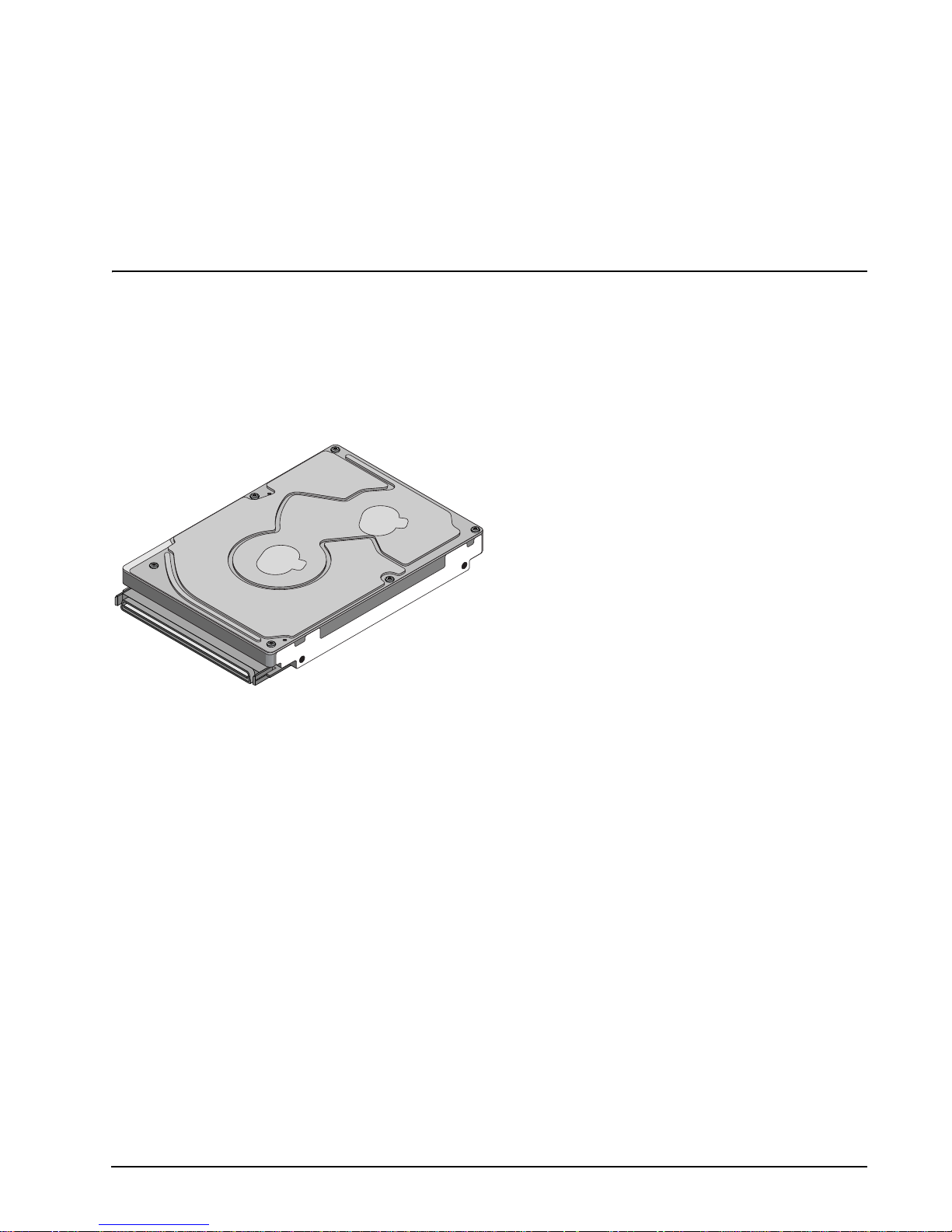
Figure 1. Savvio SCSI family drive . . . . . . . . . . . . . . . . . . . . . . . . . . . . . . . . . . . . . . . . . . . . . . . . . . . . . 1
Figure 2. Typical ST973401 drive +12 V current profile. . . . . . . . . . . . . . . . . . . . . . . . . . . . . . . . . . . . . 27
Figure 3. Typical ST973401 drive +5 V current profile. . . . . . . . . . . . . . . . . . . . . . . . . . . . . . . . . . . . . . 27
Figure 4. Typical ST936701 drive +12 V current profile. . . . . . . . . . . . . . . . . . . . . . . . . . . . . . . . . . . . . 28
Figure 5. Typical ST936701 drive +5 V current profile. . . . . . . . . . . . . . . . . . . . . . . . . . . . . . . . . . . . . . 28
Figure 6. ST973401 DC current and power vs. input/output operations per second (SE) . . . . . . . . . . 29
Figure 7. ST973401 DC current and power vs. input/output operations per second (LVD). . . . . . . . . . 29
Figure 8. ST936701 DC current and power vs. input/output operations per second (SE) . . . . . . . . . . 30
Figure 9. ST936701 DC current and power vs. input/output operations per second (LVD). . . . . . . . . . 30
Figure 10. Location of the HDA temperature check point . . . . . . . . . . . . . . . . . . . . . . . . . . . . . . . . . . . . 31
Figure 11. Recommended mounting . . . . . . . . . . . . . . . . . . . . . . . . . . . . . . . . . . . . . . . . . . . . . . . . . . . . 33
Figure 12. Mounting configuration dimensions . . . . . . . . . . . . . . . . . . . . . . . . . . . . . . . . . . . . . . . . . . . . 36
Figure 13. Air flow (suggested) . . . . . . . . . . . . . . . . . . . . . . . . . . . . . . . . . . . . . . . . . . . . . . . . . . . . . . . . 40
Figure 14. Physical interface (80-pin SCSI I/O connector) . . . . . . . . . . . . . . . . . . . . . . . . . . . . . . . . . . . 53
Figure 15. Nonshielded 80-pin SCSI “SCA-2” connector. . . . . . . . . . . . . . . . . . . . . . . . . . . . . . . . . . . . . 55
Figure 16. Typical SE-LVD alternative transmitter receiver circuits. . . . . . . . . . . . . . . . . . . . . . . . . . . . . 59
Savvio SCSI Product Manual, Rev. C iii

1.0 Scope
This manual describes Seagate® SavvioTM disc drives.
Savvio SCSI driv es s upp ort the small computer s y st em inte r fac e (S CSI) a s des c ribed i n the ANSI SCSI SP I- 3
interface specificati ons to the extent des cribed in this manual. The S CSI Interfac e Product Man ual (part num-
ber 75789509) describes general SCSI interface characteristics of this and other families of Seagate drives.
Figure 1. Savvio SCSI family drive
Savvio SCSI Product Manual, Rev. C 1

2 Savvio SCSI Product Manual, Rev. C

2.0 Applicable standards and reference documentation
The drive has been developed as a system peripheral to the highest standards of design and construction. The
drive depends upon its host equ ipment to provide adequate power and envi ronment in order to achi eve opti-
mum performance and co mpliance with applicable indus try and governmental regulations. Special attention
must be given in the areas of safety, power distribution, shielding, audible noise control, and temperature regu-
lation. In particula r, the drive must b e s ecur el y mou nted i n o rde r to gua ra nte e th e s pe ci fie d p er formance char-
acteristics. Mounting by bottom holes must meet the requirements of Section 8.3.
2.1 Standards
The Savvio SCSI fam ily compl ies with Seag ate standard s as noted in the app ropriate s ections of this Ma nual
and the Seagate SCSI Interface Product Manual, part number 75789509.
The Savvio SCSI disc dri ve is a UL re cogni zed co mponent per UL195 0, CSA ce rtifi ed to CSA C2 2.2 No. 950-
95, and VDE certified to VDE 0805 and EN60950.
2.1.1 Electromagnetic compatibility
The drive, as delivered , is designed for system integrati on and installation into a suitable encl osure prior to
use. As such the d rive is supplied as a subassembly and is not subject to Subpart B of Part 15 of the FCC
Rules and Regulation s nor the Radio Interference Reg ulations of the Canadian Departm ent of Communica-
tions.
The design characteristics of the drive serve to minimize radiation when installed in an enclosure that provides
reasonable shielding. As such, the drive is capable of meeting the Class B limits of the FCC Rules and Regula-
tions of the Canadian Department of Communications when properly packaged. However, it is the user’s
responsibility t o assure that the drive mee ts the appropriate EMI re quirements in their system. S hielded I/O
cables may be requir ed if the en closure do es not provi de adequate shieldi ng. If the I/O cab les are exte rnal to
the enclosure, shielded cables should be used, with the shields grounded to the enclosure and to the host con-
troller.
2.1.2 Electromagnetic susceptibility
As a component a ssembly, the drive is not requ ired to meet any susc eptibi lity perfor mance requ irements. It is
the responsibilit y of those integrating the driv e wit hin their systems to pe rfo rm those tests required a nd des ig n
their system to ensure th at equipment operating in the same sy stem as the drive or external to the syste m
does not adversely affect the per formance of the drive. See Section 5.1.1 and Table 2, DC power require-
ments.
Savvio SCSI Product Manual, Rev. C 3

2.2 Electromagnetic compliance
Seagate uses an indepe ndent laboratory to co nfirm compliance to the di rectives/standard(s) for CE Marking
and C-Tick Marking. The drive was tested in a representative system for typical applications. The selected system represents the most popular characteristics for test platforms. The system configurations include:
• Typical current use microprocessor
• 3.5-inch floppy disc drive
• Keyboard
• Monitor/display
• Printer
• External modem
•Mouse
Although the test system with this Seagate model complies to the directives/standard(s), we cannot guarantee
that all systems will comply. The computer manufacturer or system integrator shall confirm EMC compliance
and provide CE Marking and C-Tick Marking for their product.
Electromagnetic compliance for the European Union
If this model has the CE Marking it co mplies with the European Union requirements of the El ectromagnetic
Compatibility Directive 89 /336/EEC of 03 May 1989 as amend ed by Dir ective 92 /31/ EEC of 28 Apri l 1992 an d
Directive 93/68/EEC of 22 July 1993.
Australian C-Tick
If this model has th e C-Tick Marking it complies with the Austr alia/New Zeal and Standard AS/NZS3548 199 5
and meets the Electromagnet ic Compatibility (EMC) Framework requi rements of Australia’s Spectrum Management Agency (SMA).
Korean MIC
If this model has the Korean Ministry of Information and Communication (MIC) logo, it complies with paragraph
1 of Article 11 of the Electromagnetic Compatibility (EMC) Control Regulation and meets the Electroma gnetic
Compatibility Framework requirements of the Radio Research Laborator y (RRL) Ministry of Information and
Communication Republic of Korea.
Taiwanese BSMI
If this model has t wo Chine se words meani ng “E MC ce rtifica tion” follo wed by an eig ht digi t identifi catio n n umber, as a Marking, it complies with Chinese National Standard (CNS) 13438 and meets the Electromagnetic
Compatibility (EMC) Fra mework requ irements of the Taiwanese Bureau of Standards, Metrology, and Inspection (BSMI).
4 Savvio SCSI Product Manual, Rev. C

2.3 Reference documents
Savvio SCSI Installa ti on Guide Seagate P/N 100293076
Safety and Regulatory Agency Specifications Seagate P/N 75789512
SCSI Interface Product Manual Seagate P/N 75789509
Applicable ANSI small computer system interface (SCSI) document numbers:
T10/1143D Enhanced SCSI Parallel Interface (EPI)
T10/1416D Primary Commands-2 (SPC-3)
T10/1417D SCSI Block Commands (SBC-2)
T10/1157D SCSI Architectural Model-2 (SAM-2)
T10/1302D SPI-3 (SCSI Parallel Interface version 3)
T10/1365D SPI-4 (SCSI Parallel Interface version 4)
SFF-8451 Specification for SCA-2 Unshielded Connections
Package Test Specification Seagate P/N 30190-001 (under 100 lb.)
Package Test Specification Seagate P/N 30191-001 (over 100 lb.)
Specification, Acoustic T est Requirements, and Procedures Seagate P/N 30553-001
In case of conflict between this document and any referenced document, this document takes precedence.
Savvio SCSI Product Manual, Rev. C 5

6 Savvio SCSI Product Manual, Rev. C

3.0 General description
Savvio SCSI drives combine giant magnetoresistive (GMR) heads, partial response/maximum likelihood
(PRML) read chann el ele ct ronic s , em bed ded se r vo techno logy, and a wide Ultra320 SCSI interface to provide
high performance, h igh c apaci ty d ata s torage for a vari ety o f systems including en gin eer ing wor k statio ns , n et-
work servers, mainframes, and supercomputers.
Ultra320 SCSI uses negotiated transfer rates. These transfer rates will occur only if your host adapter supports
these data transfer rates and is compatible with the required hardware requirements of the I/O circuit type. This
drive also operates at S CSI-1 and SCSI- 2 data tran sfer rat es for backw ard compatib ility with non- Ultra/ Ultra2/
Ultra320 SCSI host adapters.
Table 1 lists the features that differentiate the Savvio SCSI models.
Table 1: Drive model number vs. differentiating features
Model number Number of heads Formatted Capacity
ST973401LC
ST936701LC
4
2
73.4 Gbytes
36.7 Gbytes
[1] See Section 9.6 for details and definitions.
The drive records and recovers data on approximately 2.5-inch (65 mm) non-removable discs.
The drive supports the Small Computer System Interface (SCSI) as described in the ANSI SCSI interface
specifications to th e e xte nt des cri bed i n th is m anu al , wh ic h d efi nes t he pr odu ct perfo rm anc e ch ar acter isti cs o f
the Savvio SCSI family of drives, and the SCSI Interface Product Manual, part number 75789509, which
describes the general interface characteristics of this and other families of Seagate SCSI drives.
The drive’s interface supports multiple initiators, disconnect/reconnect, self-configuring host software, and
automatic features that relieve the host from the necessity of knowing the physical characteristics of the targets
(logical block addressing is used).
The head and disc assembly (HDA) is sealed at the factory. Air circulates within the HDA through a non-
replaceable filter to maintain a contamination-free HDA environment.
Never disassemble the HDA a nd do not at tempt to service ite m s i n t he se aled enclosure ( hea ds, m edi a, ac tu-
ator, etc.) as this requires specia l facilities. The d rive contains no replac eable parts. Opening the HDA voids
your warranty.
Savvio SCSI drives use a dedicated landing zone at the innermost radius of the media to eliminate the possibil-
ity of destroying o r degrading data by landin g in the data zone. The drive automatically goes to the l anding
zone when power is removed.
An automatic shipping lock prevents potential damage to the heads and discs that results from movement dur-
ing shipping and handl in g. T he s hip pin g lo ck auto mat ic all y dis eng age s whe n powe r i s ap plied to the drive and
the head load process begins.
Savvio SCSI Product Manual, Rev. C 7

Savvio SCSI dr ives deco de track 0 loca tion data from the ser vo data embed ded on eac h surfa ce to eli minate
mechanical transducer adjustments and related reliability concerns.
A high-performance actuator assembly with a low-inertia, balanced, patented, straight-arm design provides
excellent performance with min im al powe r diss ipation .
3.1 Standard features
The Savvio SCSI family has the following standard features:
• Integrated Ultra320 SCSI controller
• Multimode SCSI drivers and receivers—single-ended (SE) and low voltage differential (LVD)
• 16 bit I/O data bus
• Asynchronous and synchronous data transfer protocol
• Firmware downloadable via SCSI interface
• Selectable even byte sector sizes from 512 to 528 bytes/sector
• Programmable sector reallocation scheme
• Flawed sector reallocation at format time
• Programmable auto write and read reallocation
• Reallocation of defects on command (post format)
• ECC maximum burst correction length of 320 bits
• No preventative maintenance or adjustment required
• Dedicated head landing zone
• Embedded servo design
• Self diagnostics performed when power is applied to the drive
• Zoned bit recording (ZBR)
• Vertical, horizontal, or top down mounting
• Dynamic spindle brake
• 8,192 kbytes data buffer
• Hot plug compatibility (Section 9.6.4.1 lists proper host connector needed)
• Drive Self Test (DST)
• BackGround Media Scan (BGMS)
• Data Integrity Check
•Power Save
• Supports SCSI bus fairness
3.2 Media characteristics
The media used on the drive has an alumi num sub st rat e co ated with a thin fi lm magn eti c mater ia l, over coate d
with a proprietary protective layer for improved durability and environmental protection.
3.3 Performance
• Supports industry standard Ultra320 SCSI interface
• Programmable multi-segmentable cache buffer (see Section 4.5)
• 10,000 RPM spindle. Average latency = 3.00 ms
• Command queuing of up to 64 commands
• Background processing of queue
• Supports start and stop commands (spindle stops spinning)
8 Savvio SCSI Product Manual, Rev. C

3.4 Reliability
• Mean time Between Failure (MTBF) of 1,400,000 hours
• LSI circuitry
• Balanced low mass rotary voice coil actuator
• Incorporates industry-standard Self-Monitoring, Analysis and Reporting Technology (S.M.A.R.T.)
• 5-year warranty
3.5 Formatted capacities
Standard OEM models are formatted to 512 bytes per block. The sector size is selectable at format time. Users
having the necessary equipm ent may mo dify the data block s ize before issuing a fo rmat comm and and obtain
different formatted capacities than those listed.
To provide a stable target capacity environment and at the same time provide users with flexibility if they
choose, Seagate recommends product planning in one of two modes:
1. Seagate designs specify capacity points at certain sector sizes that Seagate guarantees current and future
products will meet. We recommend custo mers use this capacity in their project pl anning, as it ensures a
stable operating point with bac kward and forwar d com patibility from gen eration to gener ation. The curren t
guaranteed operating points for this product are:
ST936701 ST973401
Sector Size
Decimal Hex Decimal Hex
512 71,687,372 445DCCC 143,374,744 88BB998
514 70,512,692 433F034 141,025,384 867E068
520 70,197,546 42F212A 140,395,092 85E4254
522 68,914,176 41B8C00 137,828,352 8371800
524 68,766,592 4194B80 137,577,184 83342E0
2. Seagate drives also may be used at the maximum available capacity at a given sector size, but the excess
capacity above the gua rantee d l ev el wi ll v ar y between other drive fami li es an d f ro m g ene ratio n to generation, depending on how eac h sector size actually forma ts out for zone frequencies and sp lits over servo
bursts. This added capaci ty potent ial may range from 0.1 to 1.3 percent above th e guarant eed capacities
listed above. Us ing th e dr ives in th is mann er gi ves the ab so lute m aximu m capacity poten tial, but the user
must determine if the extra ca pacity potential is useful, or whether their assurance of backward and forward compatibility takes precedenc e.
3.5.1 Programmable drive capacity
Using the Mode Select command, the drive can change its capacity to something less than maximum. See the
Mode Select Paramete r Lis t table in the SCS I Comman d Refer ence M anual. Re fer to t he Par ameter li st blo ck
descriptor number of blocks field. A value of zero in the number of blocks field indicates that the drive shall not
change the capacity it i s currently form atted to have. A number in t he number of bloc ks field that is less than
the maximum numbe r of LBAs changes the total driv e capacity t o the val ue in the block descripto r number o f
blocks field. A value greater than the maximum number of LBAs is rounded down to the maximum capacity.
3.6 Factory installed accessories
OEM Standard drives are shipped with the Savvio SCSI Installation Guide, part number 100293076, and the
Safety and Regulatory Agency Specifications, part number 75789512 (unless otherwise specified).
Savvio SCSI Product Manual, Rev. C 9

3.7 Options (factory installed)
All customer req uested options are inc orporated during produ ction or packaged at t he manufacturing facil ity
before shipping. Some of the options available are (not an exhaustive list of possible options):
• Other capacities can be ordered depending on sparing scheme and sector size requested.
• Single unit shipping pack. The drive is normall y shipped in bulk packagin g to provide maximum pro tection
against transit damage. Units shipped individually require additional protection as provided by the single unit
shipping pack. Users planning single unit distribution should specify this option.
• The Savvio SCSI Installation Guide , part number 100293076, i s usually include d with each standard O EM
drive shipped, but extra copies may be ordered.
• The Safety and Regulatory Agency Specifications, part nu mber 75789512, is usually included with each
standard OEM drive shipped, but extra copies may be ordered.
3.8 Accessories (user installed)
The following accessories are available. All accessories may be installed in the field.
• Single unit shipping pack.
10 Savvio SCSI Product Manual, Rev. C

4.0 Performance characteristic
4.1 Internal drive characteristics ( transparent to user)
ST973401 ST936701
Drive capacity 73.4 36.7 GBytes (formatted, rounded off values)
Read/write heads 4 2
Bytes/track 360,000 360,000 Kbytes (average, rounded off values)
Bytes/surface 18,387 18,387 Mbytes (formatted, rounded off values)
Tracks/surface (total) 51,052 51,052 Tracks (user accessible)
Tracks/inch 105 105 KTPI
Peak bits/inch 660 660 KBPI
Internal data rate 506-753 506-753 Mbits/sec (variable with zone)
Disc rotational speed 10,009 10,009 revolutions/min (RPM)
Average rotational latency 3.00 3.00 msec
4.2 SCSI performance characteristics (visible to user)
The values giv en in Section 4 .2.1 apply to a ll models of the S avvio SCSI fami ly unless otherwis e specified.
Refer to Section 9.9 and to the SCSI Interface Product Manual for additional timing details.
4.2.1 Access time [5]
Including controller overhead
(without disconnect) [1] [3]
Drive level Drive level
Not including controller overhead
(without disconnect) [1] [3]
Read Write Read Write
msec msec
Average—Typical [2] 4.70 5.10 4.50 4.90
Single Track—Typical [2] 0.65 0.95 0.45 0.75
Full Stroke—Typical [2] 8.70 9.10 8.50 8.90
4.2.2 Format command execution time (minutes)
ST973401 ST936701
[1]
Maximum (with verify) 52 26
Maximum (no verify) 26 13
Savvio SCSI Product Manual, Rev. C 11

4.2.3 Generalized performance characteristics
Minimum sector interleave 1 to 1
Data buffer transfer rate to/from disc media (one 512-byte sector):
Minimum
Maximum
[3]* 63 Mbytes/sec
[3] 94 Mbytes/sec
SCSI interface data transfer rate (asynchronous):
Maximum instantaneous one byte wide 5.0 Mbytes/sec [4]
Maximum instantaneous two bytes wide 10.0 Mbytes/sec [4]
Synchronous transfer rate Ultra320 SCSI
In low voltage differential (LVD) interface mode 5.0 to 320 Mbytes/sec
Sector Sizes:
Default 512 byte user data blocks
Variable 512 to 528 bytes per sector in even number of bytes per sector.
If n (number of bytes per sector) is odd, then n-1 will be used.
Read/write consecutive sectors on a track Yes
Flaw reallocation performance impact (for flaws reallocated at format time using
Negligible
the spare sectors per sparing zone reallocation scheme.)
Average rotational latency 3.00
msec
Notes for Section 4.2.
[1] Execution time measu red from receipt of the last by te of the Command Descriptor B lock (CDB) to the
request for a Status Byte Transfer to the Initiator (excluding connect/disconnect).
[2] Typical access times are measured u nder nom inal condi tions of te mpera ture, v oltage, and hor izontal or i-
entation as measured on a representative sample of drives.
[3] Assumes no errors and no sector has been relocated.
[4] Assumes system ability to support the rates listed and no cable loss.
[5] Access time = controller overhead + average seek time and applies to all data transfer commands.
Access to data = access time + latency time.
4.3 Start/stop time
After DC power at nomi nal vol tage has been appli ed, th e dr ive bec omes ready withi n 20 seco nds if the Mo tor
Start Option is disabled (i.e. the motor sta rts as soon as the power has be en applied). If a rec overable error
condition is detected during the start sequence, the drive executes a recovery procedure which may cause the
time to become ready to exceed 20 seco nds. During spin up to ready time the drive responds to s ome commands over the SCSI interface in less than 3 seconds after application of power. Stop time is 30 seconds from
removal of DC power.
If the Motor Start Option is enabled, the internal controller accepts the commands listed in the SCSI Command
Reference Manual less than 3 s ec ond s a fter DC power h as bee n ap pli ed . After the Moto r Start Command has
been received the dri ve becomes re ady for norma l operations withi n 20 second s typically (excluding a n error
recovery procedur e). The Motor Start Command can also be u sed to command t he drive to stop the spi ndle
(see the SCSI Command Reference Manual).
There is no power control switch on the drive.
12 Savvio SCSI Product Manual, Rev. C

4.4 Prefetch/multi-segmented cache control
The drive provides prefetch (read look-ahead) and multi-segmented cache control algorithms that in many
cases can enhance system performance. “Cache” as used herein refers to the drive buffer storage space when
it is used in cache operations. To select prefetch and cache features the host sends the Mode Select command
with the proper values in the applicable bytes in Mode Page 08h (see the SCSI Command Reference Manual).
Prefetch and cache ope ration are independent features from the standpoint that each is enabled and disabled
independently via the Mode Select command. However, in actual operation the prefetch feature overlaps
cache operation somewhat as is noted in Section 4.5.1 and 4.5.2.
All default cache and prefetch Mode paramete r values (Mode Page 08 h) for standard OEM versions of this
drive family are given in Tables 15.
4.5 Cache operation
In general, 7,100 kbytes of the physical buffer space in the drive can be used as storage space for cache operations. The buffer can be d ivided into logical segments (Mode Selec t Page 08h, byte 13) from which data is
read and to which data is written. The drive supports a maximum of 64 cache segments. The drive maintains a
table of logical block dis c medium a ddres ses of th e data stored i n eac h segm ent of the buffer. If cache operation is enabled (RCD bit = 0 in Mode P age 08h, byte 2, bit 0. See SCSI Command Referenc e Manual), data
requested by the hos t with a Read command is r etrie ved from the buffer ( if i t i s th er e) , b efo re an y di sc ac ce ss
is initiated. If c ache oper ation is no t enabl ed, the buffer (stil l se gmented with r equired num ber of s egments) is
still used, but only as circular buffer segments during disc medium read operations (disregarding Prefetch
operation for the momen t). That is, the drive does not check in the buffer segments for the requested read
data, but goes directly to the medium to retrieve it. The retrieved data merely passes through some buffer segment on the way to the h ost. On a ca che mis s, all data transfe rs to the hos t are in acc ordance wi th buffer-full
ratio rules. On a cach e hit the drive igno res the buffer-full r atio rules . See e xplanati ons assoc iated with Mode
page 02h (disconnect/reconnect control) in the SCSI Command Reference Manual.
The following is a simplified description of a read operation with cache operation enabled:
Case A - A Read command is received and the first logical block (LB) is already in cache:
1. Drive transfers to the initiator the first LB requested plus all subsequent contiguous LBs that are already in
the cache. This data may be in multiple segments.
2. When the requested LB is reached that is not in any cache segment, the drive fetches it and any remaining
requested LBs from th e disc and puts them in a segment of the cache. The dri ve transfers the re maining
requested LBs from the ca che to t he host in accorda nce with the disconn ect/r econn ect speci fication mentioned above.
3. If the prefetch feature is enabled, refer to Section 4.5.2 for operation from this point.
Case B - A Read command requests data, the first LB of which is not in any segment of the cache:
1. The drive fetches the requested LBs from the disc and transfers them into a segment, and from there to
the host in accordance with the disconnect/reconnect specification referred to in case A.
2. If the prefetch feature is enabled, refer to Section 4.5.2 for operation from this point.
Each buffer segment is act ually a self-containe d circular sto rage (wrap-arou nd occurs), the length of which is
an integer number of disc medium sectors. The wrap-around capability of the individual segments greatly
enhances the buffer’s overall performance as a cache storage, allowing a wide range of user selectable configurations, which includes their use in the prefetch operation (if enabled), even when cache operation is disabled
(see Section 4.5.2) . The number of segments is s et dynamically by t he drive and cannot be s et by the host.
The size in Kbytes of eac h segment is not reported by the Mode Sen se co mma nd page 08 h, by tes 14 and 15 .
The value 0XFFFF is always reported. If a size specification is sent by the host in a Mode Selec t command
(bytes 14 and 15) no new segment size is set up by the drive, and if the STRICT bit in Mode page 00h (byte 2,
bit 1) is set to one, the drive resp onds as it does for any attempt to chan ge unchangeable parameter s (see
SCSI Command Reference Manual).
Savvio SCSI Product Manual, Rev. C 13

4.5.1 Caching write data
Write caching is a write operation by the d rive th at makes u se of a dr ive b uffer s to rage ar ea wher e the da ta to
be written to the medium is stored in one or more segments while the drive performs the write command.
If read caching is enabled (RCD=0), then data written to the medium is retained in the cache to be made available for future read cache h its. The same buffer space an d segme ntation is use d as set up for read functions .
The buffer segmentation s cheme is set up or changed independently, having nothing to do with the state of
RCD. When a write command is issued, i f RCD=0, the cache is first checke d to see if any logical blocks tha t
are to be written are a lready stored in the cache f rom a previous read or write comman d. If there are, the
respective cache segments are cleared. The new data is cached for subsequent Read commands.
If the number of write data logi cal block s exceeds th e size of the s egment being wr itten into, whe n the end of
the segment is reached, the data is written into the beginning of the same cache segment, overwriting the data
that was written there at the beginning of the operation. However, the drive does not overwrite data that has not
yet been written to the medium.
If write caching is enabled (WCE=1), then the drive may return GOOD status on a write command after the
data has been transferred into the cache, but before the data has been written to the medium. If an error
occurs while writing the data to the medium, and GOOD status has already been returned, a deferred error will
be generated.
The Synchronize Cache command may be used to force the drive to write all cached write data to the medium.
Upon completion of a Synchronize Cache command, all data received from previous write commands will have
been written to the medium.
Tables 15 show Mode default settings for the drives.
4.5.2 Prefetch operation
If the Prefetch fea ture i s ena bl ed, data in co nti guo us lo gic al b lock s on t he d is c immediately beyond tha t whi c h
was requested by a Read command can be re trieved and stored in the buffer for i mmediate transfer from the
buffer to the host on subseque nt Read com mands that request t hose logica l block s (this is tr ue even if cache
operation is disabled). Though the prefetch operation uses the buffer as a cache, finding the requested data in
the buffer is a prefetch hit, not a cache operation hit. Prefetch is enabled using Mode Select page 08h, byte 12,
bit 5 (Disable Read Ahead - DRA bit). DRA bi t = 0 enables prefetch. S ince data that is prefetc hed replaces
data already in some buffer segment(s ), the hos t can lim it the amou nt of pr efet ch data to optimi z e syst em performance. The max prefetch field (bytes 8 a nd 9) limits the amount of pref etch. The drive does not use the
Prefetch Ceiling field (bytes 10 and 11).
During a prefetch operati on, the dri ve crosses a cylinde r boundary to fetch mor e data only if th e Discontinu ity
(DISC) bit is set to one in bit 4 of byte 2 of Mode parameters page 08h.
Whenever prefetch ( re ad loo k-ah ead) is enabled ( ena ble d b y DRA = 0), i t o per at es und er th e c on tro l of A RLA
(Adaptive Read Look-Ahead). If the host uses software interleave, ARLA enables prefetch of contiguous
blocks from the disc when it senses that a prefetch hit will likely occur, even if two consecutive read operations
were not for physically con tiguou s blocks of da ta (e.g., “software i nterleave”) . ARLA disab les prefetc h when it
decides that a prefetch hit will not likely occur. If the host is not using software interleave, and if two sequential
read operations are no t for c ontiguous bloc ks of data , ARLA d isables pr efetc h, but as long as seq uentia l read
operations request contiguous blocks of data, ARLA keeps prefetch enabled.
4.5.3 Optimizing cache performance for desktop and server applications
Desktop and server applications require different drive caching operations for optimal performance. This
means it is difficult to provide a single configuration that meets both of these needs. In a desktop environment,
you want to configure the ca che to respond quic kly to repetitive acc esses of multiple sm all segments of data
without taking the time to “look ahea d” to the next conti guous segmen ts of data. In a server environ ment, you
14 Savvio SCSI Product Manual, Rev. C

want to configure the cac he to provide large volumes of seque ntial data in a non-repetitive manner. In this
case, the ability of the cache to “look ahead” to the next contiguous segmen ts of sequential data is a good
thing.
The Performance Mode (PM) bit contr ols the way the drive switches the cache buffer into different modes o f
segmentation. In “server mode” (PM bit = 0), the drive can dynamically cha nge the number of cache buffer
segments as needed to opt imize the performa nce, based on the command st ream from the hos t. In “desktop
mode” (PM bit = 1), the number of segments is maintained at the value defined in Mode Page 8, Byte 13, at all
times (unless changed by using a Mode Select command). For additional information about the PM bit, refer to
the Unit Attention Param eters page (00h) of the Mode Sense command (1Ah) in the SCSI Interfac e Product
Manual, part number 75789509.
Savvio SCSI Product Manual, Rev. C 15

16 Savvio SCSI Product Manual, Rev. C

5.0 Reliability specifications
The following reliabi lity specifications assume cor rect host/drive operational interfa ce, including all interface
timings, power supply voltages, environmental requirements and drive mounting constraints (see Section 8.3).
Seek Errors
Less than 10 in 10
Read Error Rates [1]
Recovered Data Less than 10 errors in 10
Unrecovered Data Less than 1 sector in 10
Miscorrected Data Less than 1 sector in 10
MTBF 1,400,000 hours
Service Life 5 years
Preventive Maintenance None required
Note.
[1] Error rate specified with automatic retries and data correction with ECC enabled and all flaws reallocated.
5.1 Error rates
The error rates stated in this specification assume the following:
• The drive is operated per this specification using DC power as defined in this manual (see Section 6.2).
• The drive has been formatted with the SCSI FORMA T command.
• Errors caused by me dia defects or host sy s tem fai lure s are e xc lu ded from er r or r ate c omp utations. Refer t o
Section 3.2, “Media Characteristics.”
• Assume random data.
8
seeks
12
bits transferred (OEM default settings)
15
bits transferred (OEM default settings)
21
bits transferred
5.1.1 Environmental interference
When evaluating s ystems ope ration under cond itions o f Electro magnetic Interferen ce (EMI) , the per formance
of the drive within the system sh all be consid ered acce ptable if the drive do es not gener ate an unrec overable
condition.
An unrecoverable error, or unrecoverable condition, is defined as one that:
• Is not detected and corrected by the drive itself;
• Is not capable of being detected from the error or fault status provided through the drive or SCSI interface; or
• Is not capable of being recovered by normal drive or system recovery procedures without operator intervention.
Savvio SCSI Product Manual, Rev. C 17

5.1.2 Read errors
Before determination or measurement of read error rates:
• The data that is to be used for measurement of read error rates must be verified as being written correctly on
the media.
• All media defect induced errors must be excluded from error rate calculations.
5.1.3 Write errors
Write errors can occur as a result of media defects, envi ronmental interfe rence, or equipm ent malfunction.
Therefore, write errors are not predictable as a function of the number of bits passed.
If an unrecoverable write error occurs because of an equ ipm ent malfu nctio n in the drive , the error is classi fied
as a failure affecting MTBF. Unrecoverable write errors are those which cannot be corrected within two
attempts at writing the record with a read verify after each attempt (excluding media defects).
5.1.4 Seek errors
A seek error is de fine d a s a failu re of t he d ri ve to pos it ion the heads to the addressed tra ck. T h er e shal l be n o
more than ten recoverable seek errors in 10
8
physical seek operations. After detecting an initial seek error, the
drive automatical ly perfor ms an error recovery process. If the err or recovery process fai ls, a see k positionin g
error (15h) is rep orted with a Hard ware error (4h) rep orted in the Sens e Key. This is an unrecoverable seek
error. Unrecoverable seek errors are classified as fa ilures for MTBF calculati ons. Refer to the SCSI Interfac e
Product Manual, part number 75789509, for Request Sense information.
5.2 Reliability and service
You can enhance the reliability of Savvio SCSI disc drives by ensu ring that the drive rec eives adequat e cooling. Section 6 provid es temperature measurements an d other information that may be used t o enhance the
service life of the drive. Section 8.2 provides recommended air-flow information.
5.2.1 Mean time between failure
The production disc dri ve shall achieve an MTBF of 1 ,400,000 hours when operate d in an environment that
ensures the HDA case t emperatures specified in Section 6.4 are not ex ceeded. Short-term ex cursions up to
the specificatio n limits of the ope rating en vironm ent will no t affect MTBF pe rformance. Continua l or sustaine d
operation at case temperatures above the values shown in Section 6.4.1 may degrade product reliability.
The MTBF target is specified as device power-on hours (POH) for all drives in service per failure.
Estimated power-on operating hours in the period = MTBF per measurement period
Number of drive failures in the period
Estimated power-on operation hours means power-up hours per disc drive times the total number of disc
drives in service. Ea ch dis c drive shall h ave accu mulate d at le ast nine months of operatio n. Data sha ll be ca lculated on a rolling average base for a minimum period of six months.
MTBF is based on the following assumptions:
• 8,760 power-on hours per year.
• 250 average on/off cycles per year.
• Operations at nominal voltages.
• Systems will prov ide adequate coolin g to ensure the case temperatures specified in Sec tion 6.4.1 are not
exceeded.
Drive failure means any stoppage or substandard performance caused by drive malfunction.
18 Savvio SCSI Product Manual, Rev. C

A S.M.A.R.T. predictive failure indic ates that the dri ve is deterior ating to an immin ent failu re and is co nside red
an MTBF hit.
5.2.2 Preventive maintenance
No routine scheduled preventive maintenance shall be required.
5.2.3 Service life
The drive shall ha ve a us eful ser vice l ife of fi ve years. Depot r epair or re place ment of m ajor parts is permitte d
during the lifetime (see Section 5.2.4).
5.2.4 Service philosophy
Special equipment is required to repair the drive HDA. In order to achieve the abo ve service lif e, repairs must
be performed only a t a pro perly e quippe d and s taffed service and repair facility. Troubleshooting and repair of
PCBs in the field is not recomm ended, because of the extensiv e diagnostic equipment req uired for effective
servicing. Also, there are no spare parts available for this drive. Drive warranty is voided if the HDA is opened.
5.2.5 Service tools
No special tools are required for site installation or recommended for site maintenance. Refer to Section 5.2.4.
The depot repair philosophy of the drive precludes the necessity for special tools. Field repair of the drive is not
practical since there are no user purchasable parts in the drive.
5.2.6 Hot plugging Savvio SCSI disc drives
The ANSI SPI-3 (T10/13 02D) document defines the physical requir ements for removal and insertion of SCSI
devices on the SCSI bus. Four cases are addressed. The cases are differentiated by the state of the SCSI bus
when the removal or insertion occurs.
Case 1 - All bus devices powered off during removal or insertion
Case 2 - RST signal asserted continuously during removal or insertion
Case 3 - Current I/O processes not allowed during insertion or removal
Case 4 - Current I/O process allowed during insertion or removal, except on the device being changed
Seagate Savvio S CSI disc d rives supp ort all four hot pluggi ng cases. Provision sh all be mad e by the s ystem
such that a device being ins erted make s power and groun d connecti ons prior to the c onnectio n of any device
signal contact to the bus. A d evice bein g remov ed sha ll ma intain powe r and gr ound c onnec tions after the di sconnection of any dev ic e sig nal c ontact f ro m th e bu s ( see S F F-8 451 Specificatio n fo r SC A-2 Uns hi eld ed C onnections).
It is the responsibility of the systems integrator to assure that no hazards from temperature, energy, voltage, or
ESD potential are presented during the hot connect/disconnect operation.
All I/O processes for th e SCSI device bein g inserted or remov ed shall be quiesc ent. All SCSI devices on the
bus shall have receivers that conform to the SPI-3 standard.
If the device being hot plugged uses single-ended (SE) drivers and the bus is currently operating in low voltage
differential (LVD) mode, then all I/O processes fo r all dev ices on the bus must be compl eted, an d the bus quiesced, before attempting to hot plug. Following the insertion of the newly installed device, the SCSI host
adapter must issue a Bus Reset, fol lowed by a sy nchronous transfer ne gotiation . Failure to per form the SCSI
Bus Reset could result in erroneous bus operations.
The SCSI bus termination and termination power source shall be external to the device being inserted or
removed.
Savvio SCSI Product Manual, Rev. C 19

End users shoul d not mix devices with high vol tage differential (HVD) driv ers and r eceivers a nd devices with
SE, LVD, or multimode drivers and receivers on the same SCSI bu s since the comm on mode vo ltages in the
HVD environment may not be controlled to safe levels for SE and LVD devices (see ANSI SPI-3).
The disc drive s pindle must come to a complete s top prior to completely removing the drive from the cabine t
chassis. Use of th e Stop Spindle command or partial withdr awal of the drive, e nou gh to b e disco nnecte d fro m
the power source, prior to removal are methods for insuring that this requirement is met. During drive insertion,
care should be taken to avoid exceeding the limits stated in Section 6.4.4, "Shock and vibration" in this manual.
5.2.7 S.M.A.R.T.
S.M.A.R.T. is an acronym for Self-Mo nitoring Ana lysis and Re porting Technology. T his technol ogy is intende d
to recognize condi tions that i ndicate a dri ve fai lure an d is d esigned to p rovide sufficie nt warn ing of a f ailure t o
allow data back-up before an actual failure occurs.
Note. The firmwa re will monitor s pecific attribute s for degradation over time but canno t predict instanta-
neous drive failures.
Each attribute has been selected to mo nit o r a s pe ci fic set o f fa il ure c ond iti ons i n th e o perati ng performance of
the drive, and the thresholds are optimized to minimize “false” and “failed” predictions.
Controlling S.M.A.R.T.
The operating mode of S.M .A.R.T. is controlled by the DEX CPT bit and the PERF bit of the “ Informational
Exceptions Control Mo de Page” (1Ch) . The DEXCPT bit i s used to enable or di sable the S .M.A.R.T. process.
Setting the DEXCPT bit will disable all S.M.A.R.T . functions. When enabled, S.M.A.R.T. will collect on-line data
as the drive performs no rmal read/wri te oper ations. W hen th e PERF bi t is set , the dr ive is c onsidered to b e in
“On-line Mode Only” and will not perform off-line functions.
The process of measuring off-line attributes and saving data can be forced by the Rezero Unit command. Forcing S.M.A.R.T. will reset the timer so that the next scheduled interrupt will be two hours.
The drive can be interrogated by the host to determine the time remaining before the next scheduled measurement and data logging process will occu r. This is accomplished by a log sense command to log page 0x3E.
The purpose is to allow the customer to control when S.M.A.R.T. interruptions occur. As described above, forcing S.M.A.R.T by the Rezero Unit command will reset the timer.
Performance impact
S.M.A.R.T . attribute data will be saved to the disc for the purpose of recreating the events that caused a predictive failure. The driv e wi ll measure and save parameter s on ce ever y tw o hou rs subj ec t to an idl e p er iod on th e
SCSI bus. The process of measu ring off-line attribute data and saving data to the disc is uninterruptable and
the maximum delay is summarized below:
Maximum processing delay
On-line only delay Fully enabled delay
DEXCPT = 0, PERF = 1 DEXCPT = 0, PERF = 0
S.M.A.R.T. delay times 60 milliseconds 370 milliseconds
Reporting control
Reporting is contr olled in the Inform ational Exceptions Control Page (1Ch). Subject to the repo rting method,
the firmware will is sue a 01-5D00 sense code to th e h ost . T he erro r co de i s pr es erve d th ro ugh bus res ets an d
power cycles.
20 Savvio SCSI Product Manual, Rev. C

Determining rate
S.M.A.R.T. monitors the rate at which error s occur and signal s a predic tive fai lure if the rate of degra ded error
rate increases to an un acce ptab le le ve l. To determine rate, error events are logged and compar ed to the number of total operations for a given attribut e. The interval define s the number of operatio ns over which to measure the rate. The counter that kee ps track of the current number of oper ations is referred to as the Interval
Counter.
S.M.A.R.T. measures error rate, hen ce for each attribute the occurrence of a n error is recorded. A counter
keeps track of the number of errors for the current interval. This counter is referred to as the Failure Counter.
Error rate is simpl y the number of errors per operation. T he algorithm t hat S.M.A. R.T. uses to reco rd rates o f
error is to set thresholds for the number of errors and the interval. If the number of errors exceeds the threshold
before the interval expires , then the error rate i s considered to be un acceptable. If the num ber of errors does
not exceed the threshol d before the interval expires, then the error rate is cons idered to be acceptable. In
either case, the interval and failure counters are reset and the process starts over.
Predictive failures
S.M.A.R.T. signals predictive failures when the dri ve is perfor ming unacc eptably for a period of time. Th e firmware keeps a running count of the number of times the error rate for each attribute is unacceptable. To accomplish this, a counter is incre mented wheneve r the error rate is unacc eptable and decremen ted (not to exceed
zero) whenever the error rate is acceptable. Should the counter continually be incremented such that it
reaches the predi ctive th resh old, a pred ictive failure is s ignal ed. This cou nter is refe rred to as the Failu re Hi story Counter. There is a separate Failure History Counter for each attribute.
5.2.8 Thermal monitor
Savvio SCSI drives implement a temperature warning system which:
1. Signals the host if the temperature exceeds a value which would threaten the drive.
2. Signals the host if the temperature exceeds a user-specified value.
3. Saves a S.M.A.R.T. data frame on the drive which exceed the threatening temperature value.
A temperature sensor monito rs the drive temperature and is sues a warning over the inte rface when the tem-
perature exceeds a s et threshol d. The tem perature is measured at power-up an d then at ten-minute intervals
after power-up.
The thermal monitor syste m generates a wa rning code of 01- 0B01 when the temp erature exceed s the specified limit in compl iance with the SCSI standard. T he drive temperature is repo rted in the FRU code field o f
mode sense data. You can use this information to determine if the warning is due to the temperature exceeding
the drive threatening temperature or the user-specified temperature.
This feature is controlled by the Enable Warning (EWasc) bit, and the reporting mechanism is controlled by the
Method of Reporting Informational Exceptions field (MRIE) on the Informational Exceptions Control (IEC)
mode page (1Ch).
The current algorithm impl ements two temperature trip points. The first trip point is set at 68°C which is the
maximum temperatur e limit a ccordi ng to th e dri ve spec ific ation. T he secon d trip point is us er-se lectable using
the Log Select com mand. The reference tempe rature parameter in the tem perature log page (see Table 11)
Savvio SCSI Product Manual, Rev. C 21

can be used to set this trip point. The default value for this drive is 68°C, however, you can set it to any va lue in
the range of 0 to 68°C. If you s pec i fy a temp erature greater than 68°C in th is fie ld, the te mpe ratur e i s rou nde d
down to
68°C. A sense code is sent to the host to indicate the rounding of the parameter field.
Table 11: Temperature Log page (0Dh)
Parameter Code Description
0000h
0001h
Primary Temperature
Reference Temperature
When the first temperature trip point is exceeded, S.M.A.R.T. data is collected and a frame is saved to the disc.
5.2.9 Drive Self Test (DST)
Drive Self Test (DST) is a technolo gy designed to recognize drive fault conditions that qualify the drive as a
failed unit. DST validates the functionality of the drive at a system level.
There are two test coverage options implemented in DST:
1. Extended test
2. Short text
The most thorough option is the extended test that performs various tests on the drive and scans every logical
block address (LBA ) of the drive. The s hort test is time-res tricted and limited i n length—it does not s can the
entire media surface, but does some fundamental tests and scans portions of the media.
If DST encounters an err or during either of these tests, it r eports a fault condition. If the drive f ails the test,
remove it from service and return it to Seagate for service.
5.2.9.1 DST Failure Definition
The drive will presen t a “diagnostic failed” con dition through the self-te sts results value of the diagnos tic log
page if a functional failur e is enco untered du ring DST. The channel and servo parameters are not mod ified to
test the drive more strin gently, and the number of retries are not redu ced. All retries and recovery proce sses
are enabled during the test. If data is recoverable, no failure condition will be reported regardless of the number
of retries required to recover the data.
The following conditions are considered DST failure conditions:
• Seek error after retries are exhausted
• Track-follow error after retries are exhausted
• Read error after retries are exhausted
• Write error after retries are exhausted
Recovered errors will not be reported as diagnostic failures.
5.2.9.2 Implementation
This section provides all of the information necessary to implement the DST function on this drive.
5.2.9.2.1 State of the drive prior to testing
The drive must be in a ready state before issuing the Send Diagno stic command . There are multipl e reasons
why a drive may not be ready, some of which are valid conditions, and not errors. For example, a drive may be
in process of doing a format, or another DST . It is the responsibility of the host application to determine the “not
ready” cause.
22 Savvio SCSI Product Manual, Rev. C

While not technically part of DST, a Not Ready condition also qualifies the drive to be returned to Seagate as a
failed drive.
A Drive Not Ready condition is reported by the drive under the following conditions:
• Motor will not spin
• Motor will not lock to speed
• Servo will not lock on track
• Drive cannot read configuration tables from the disc
In these conditions, the drive responds to a Test Unit Ready command with an 02/04/00 or 02/04/03 code.
5.2.9.2.2 Invoking DST
To in voke DST, submit the Send Diagnostic comman d with the ap propriate F unction Code (001b for the shor t
test or 010b for the extended tes t) in bytes 1, bits 5, 6, and 7. Refer to the Seagate SCSI Interface Product
Manual, part number 75789509, for additional information about invoking DST.
5.2.9.2.3 Short and extended tests
DST has two testing options:
1. short
2. extended
These testing options are described in the following two subsections.
Each test consists of th ree s egm ents: a n el ec tric al test s egm ent, a servo test segment , and a r ea d/v erify s ca n
segment.
Short test (Function Code: 001b)
The purpose of the short test is to pr ov ide a ti me-l imi ted te st that tests as much o f th e dr iv e as po ss ib le wi thi n
120 seconds. The shor t test does not scan the entire me dia surface, but does some funda mental tests and
scans portions of the media. A complete read/verify scan is not performed and only factual failures will report a
fault condition. This option provides a quick confidence test of the drive.
Extended test (Function Code: 010b)
The objective of the extended test option is to empirically test critical drive components. For example, the seek
tests and on-track operations tes t the pos it ion ing mec han ism. T he read operation tests the read head elemen t
and the media surface. The write element is tested throu gh read/write/read operations. The inte grity of the
media is checked through a r ead/verif y scan of the med ia. Motor functio nality is tested by d efault as a part of
these tests.
The anticipated length of the Extended test is reported through the Control Mode page.
5.2.9.2.4 Log page entries
When the drive begi ns DST, it creates a new entry in the Self -te st Resul ts Log page . The new entr y is c reated
by inserting a new self-test parameter block at the beginning of the self-test results log parameter section of the
log page. Existing da ta will be moved to make room f or the new param eter b lock . T he driv e r ep or ts 20 par ameter blocks in the log page. If there are more than 20 parameter blocks, the least recent parameter block will be
deleted. The new parameter block will be initialized as follows:
1. The Function Code field is set to the same value as sent in the DST command
2. The Self-Test Results Value field is set to Fh
3. The drive will store the log page to non-volatile memory
Savvio SCSI Product Manual, Rev. C 23

After a self-test is complete or has been aborted, the dri ve upda tes the Sel f-Test Results Value field in its SelfTest Results Lo g pa ge in n on- v ola til e m emo ry. The host may use Log Sense to read the resul ts from up to th e
last 20 self-tests performed by the drive. The self-test results value is a 4-bit field that reports the results of the
test. If the field i s zero, the drive pas sed with no errors detected by the DST. If the field is not zero , the test
failed for the reason reported in the field.
The drive will report th e failure condition and LBA (if applicable) in the Self-t est Results Log parameter. The
Sense key, ASC, ASCQ, and FRU are used to report the failure condition.
5.2.9.2.5 Abort
There are several ways to abort a diagnostic. You can use a SCSI Bus Reset or a Bus Device Reset message
to abort the diagnostic.
You can abort a DST executing in backgrou nd mode by using the a bort code in t he DST Functio n Code field .
This will cause a 01 ( self-test aborted b y the application cl ient) code to appear i n the self-test results v alues
log. All other abort mechanisms will be reported as a 02 (self-test routine was interrupted by a reset condition).
5.2.10 Product warr anty
Beginning on the date of shipment to customer and continuing for a period of five years, Seagate warrants that
each product (including components and subassemblies) or spare part that fails to function properly under normal use due to defect in mate rials on workm anship or due to no nconfo rmance to the appl icable s pecif ications
will be repaired or rep laced, at Seagate’s optio n an d a t no ch ar ge to c ustomer, if returned by customer at cu stomer’s expens e to Seagate’s designated faci lity in accordance wit h Seagate’s warranty procedur e. Seagate
will pay for transporting the repair or replacement item to custom er. F or more detailed warranty informat ion
refer to the Standard terms and conditions of Purchase for Seagate products.
Shipping
When transporting or shipping a dr ive, a Seagate approved container mus t be used. Keep your original box.
They are easily identified by the Seagate-approved package label . Shipping a drive in a non-approved container voids the drive warranty.
Seagate repair center s may refuse rece ipt of co mpo nen ts imp ro per l y packa ged or o bv iou sly da mag ed in transit. Contact your Autho r iz ed Se agat e Di s tribu tor to pu rc ha se add iti on al box es . Se a gate re comm ends shipping
by an air-ride carrier experienced in handling computer equipment.
Product repair and return information
Seagate customer se rvice centers are th e only facilities au thorized to service Sea gate drives. Seagate d oes
not sanction any third- party repair facilities. Any unau thorized repair or tampering with the fact ory-seal voids
the warranty.
24 Savvio SCSI Product Manual, Rev. C

6.0 Physical/electrical spe cifications
This section provides information relating to the physical and electrical characteristics of the Savvio SCSI
drive.
6.1 AC power requirements
None.
6.2 DC power requirements
The voltage and current requirements for a single drive are shown in the following table. Values indicated apply
at the drive power connector. The table shows current values in Amperes.
Table 2: DC power requirements
Notes
Voltage +5V +12 V +5V +12 V +5V +12 V +5V +12 V
Regulation [5] +10%/
Average idle current DC X
Maximum starting current
(peak DC) DC 3σ
(peak AC) AC 3σ
Delayed motor start (max) DC 3σ [1][4] 0.49 0.05 0.48 0.05 0.49 0.05 0.49 0.05
Peak operating current
DC X
Maximum DC 3σ
Maximum (peak) DC 3σ
[1][7] 0.51 0.21 0.50 0.21 0.51 0.19 0.50 0.19
[3]
[3] 0.68
[1][6]
[1] 0.73
SE mode LVD mode SE mode LVD mode
-7.5%
1.01
0.75
1.12
ST973401 ST936701
+10%/
-7.5%[2]
1.68
2.70
0.40
0.46
1.50
+10%/
-7.5%
0.72
1.14
0.74
0.75
1.32
+10%/
-7.5%[2]
1.68
2.65
0.43
0.49
1.54
+10%/
-7.5%
0.70
1.00
0.74
0.76
1.14
+10%/
-7.5%[2]
1.58
2.68
0.46
0.49
1.48
+10%/
-7.5%
0.65
1.03
0.69
0.74
1.30
+10%/
-7.5%[2]
1.58
2.66
0.47
0.49
1.48
[1] Measured with avera ge re adi ng D C am mete r or equ iv alent s am pl ing sc op e. I nstan taneou s c urr ent pea ks
will exceed these value s. Power supply at nom inal voltage. Number of driv es tested = 6, 35
De grees C
ambient.
[2] For +12 V, a –10% tolerance is permissible during in itial start of spindle , and must return t o ±5% before
10,000 rpm is rea ched. The ±5% must b e main tained after the dri ve sign ifies th at its power-up se quence
has been completed and that the drive is able to accept selection by the host initiator.
[3] See +12 V current profile in Figure 2.
[4] This condition occu rs when the Motor Start Option is ena bled and the drive has not yet receiv ed a Start
Motor command.
[5] See Section 6.2.1 “Con ducted Noise Immunity.” Specified voltage tolerance is inclusive of r ipple, noise,
and transient response.
Savvio SCSI Product Manual, Rev. C 25

[6] Operating condition is defined as random 8 block reads at:
259
I/Os per second (ST973401LC)
259
I/Os per second (ST936701LC)
[7] During idle, the d rive heads are reloca ted every 60 seconds to a random location within the band from
three-quarters to maximum track.
General Notes from Table 2:
1. Minimum current l oading fo r each sup ply voltage is not les s than 1. 2% of the ma ximum o perating current
shown.
2. The +5 and +12 volt supplies shall employ separate ground returns.
3. Where power is provided to multiple drives from a common supply, careful consideration for individual
drive power requirem ents s hou ld b e no ted. Whe re mul ti ple uni ts are pow er ed o n s imu ltaneou sl y, the peak
starting current must be available to each device.
4. Parameters, other than spindle start, are measured after a 10-minute warm up.
5. No terminator power.
6.2.1 Conducted noise immunity
Noise is specified a s a periodic an d random distri bution of frequenc ies covering a band from DC to 10 MHz.
Maximum allowed noise values given below are peak to peak measurements and apply at the drive power connector.
+5 V = 250 mV pp from 100 hz to 20 Mhz.
+12 V = 800 mV pp from 100 hz to 8 Khz;
450 mV pp from 8 Khz to 20 Khz;
250 mV pp from 20 Khz to 5 Mhz.
6.2.2 Power sequencing
The drive does not require power sequenci ng. The drive prote cts against inadver tent writing dur ing power-up
and down. Daisy-chain oper ation requires that power be maintained on the SCSI bus termi nator to ensure
proper termination of the peripheral I/O cables. T o automatically delay motor start based on the target ID (SCSI
ID) enable the Delay Motor Start option and disable the E nable Motor Start option on the backplane. To delay
the motor until the dr ive rece ives a Start Unit command, en able the Enable Re mote Motor Start option on the
backplane.
6.2.3 12 V - Current profile
Figure 2 and 4 identify the drive +12 V curr ent pr ofiles and fi gures 3 and 5 iden tify the dr ive +5 V c urrent profiles. The current during the various times is as shown:
T0 - Power is applied to the drive.
T1 - Controller self tests are performed.
T2 - Spindle begins to accelerate under current limiting after performing drive internal
diagnostics. See Note 1 of Table 2.
T3 - The spindle is up to speed and the head-arm restraint is unlocked.
T4 - The adaptive servo calibration sequence is performed.
T5 - Calibration is complete and drive is ready for reading and writing.
Note. All times and currents are typical. See Table 2 for maximum current requirements.
26 Savvio SCSI Product Manual, Rev. C

Figure 2. Typical ST973401 drive +12 V current profile
Figure 3. Typical ST973401 drive +5 V current profile
Savvio SCSI Product Manual, Rev. C 27

Figure 4. Typical ST936701 drive +12 V current profile
Figure 5. Typical ST936701 drive +5 V current profile
28 Savvio SCSI Product Manual, Rev. C

6.3 Power dissipation
ST973401
For drives using single-ended interface circuits, typical power di ssipation under idle con ditions is 5.07 watts
(17.3 BTUs per hour).
For drives using low voltage differential interface circuits, typical power dissipation under idle conditions is 5.02
watts (17.1 BTUs per hour).
To ob tain operating power for typ ical random read oper ations, refer to the foll owing two I/O rate curv es (see
Figures 6 and 7). Loc ate th e typical I/O rate for a drive in your s yst em on the horizontal axis and r ea d th e cor responding +5 volt curr ent, +12 volt current, and to tal watts on the vertical axis. To calculate BTUs per hour,
multiply watts by 3.4123.
ST 973401L C DC CURRENT/POWE R vs THRO UGHPUT (Single Ended)
1.400
1.200
R an dom 8 Bl ock Reads
14 .0 0
12 .0 0
5Volt A
12 V o l t A
Watts
1.000
0.800
0.600
Amperes
0.400
0.200
0.000
0.0 50.0 100.0 150.0 200.0 250.0 300.0
10 .0 0
8.00
6.00
4.00
2.00
0.00
Power (watts)
I/Os per Second
Figure 6. ST973401 DC current and power vs. input/output operations per second (SE)
ST973401LC DC CURRENT/POWER vs THROUGHPUT (Low Voltage Differential)
1.4 0 0
1.2 0 0
1.0 0 0
0.800
Random 8 Block Reads
14. 0 0
12. 0 0
10. 0 0
8.00
Power (watts)
5Volt A
12 V o l t A
Watts
0.600
Amperes
0.400
0.200
0.000
0.0 50.0 100.0 150.0 200.0 250.0 300. 0
Figure 7.
ST973401 DC current and power vs. input/output operations per second (LVD)
Savvio SCSI Product Manual, Rev. C 29
6.00
4.00
2.00
0.00
I/Os per Second

ST936701
For drives using single-ended interface ci rcuits, typical power diss ipation under idle condi tions is 4.83 watts
(16.5 BTUs per hour).
For drives using low voltage differential interface circuits, typical power dissipation under idle conditions is
4.83
watts (16.5 BTUs per hour).
To ob tain operating power for typ ical random read o perations, refer to the f ollowing two I/O rate cur ves (see
Figures 6 and 7). Loc ate th e typical I/O rate f or a dr ive in your system on the ho ri zo ntal a xis and r ea d th e c orresponding +5 volt curr ent, +12 volt current, and to tal watts on the vertical axis. To calculate BTUs per hour,
multiply watts by 3.4123.
ST 93 6701LC DC CURRENT/POWER vs THROUGHPUT (Single Ended)
1.4 0 0
1.2 0 0
1.0 0 0
0.800
0.600
Amperes
0.400
0.200
0.000
0.0 50.0 100.0 150.0 200.0 250.0 300.0
R andom 8 Blo ck Reads
I/Os per Second
14 .0 0
12 .0 0
10 .0 0
8.00
6.00
4.00
2.00
0.00
5Volt A
12 Vo lt A
Watts
Power (watts)
Figure 8. ST936701 DC current and power vs. input/output operations per second (SE)
ST 936 701LC DC CURRENT/POWER vs THROUGHPUT (Low Voltage Differential)
1.4 0 0
1.2 0 0
1.0 0 0
0.800
0.600
Amperes
0.400
0.200
0.000
0.0 50.0 100.0 150.0 200.0 250.0 300.0
Figure 9.
ST936701 DC current and power vs. input/output operations per second (LVD)
R andom 8 Blo ck Reads
I/Os per Second
14 .0 0
12 .0 0
10 .0 0
8.00
6.00
4.00
2.00
0.00
Power (watts)
5Volt A
12 Vo lt A
Watts
30 Savvio SCSI Product Manual, Rev. C

6.4 Environmental limits
Tempe ratur e an d hum idi ty val ues ex per i enced by the drive mus t be suc h that c ond ens ation does not oc c ur on
any drive part. Altitude and atmospheric pressu re specifications are refer enced to a standard day at 58.7 °F
(14.8°C). Maximum wet bulb temperature is
6.4.1 Temperature
a. Operating
With cooling designe d to maintain the case temper atures, the dr ive meets all s pecificati ons over a 41° F to
131°F (5°C to 55°C) drive ambient temperature range with a maximum temperature gradient of 36°F (20°C)
per hour. The enclosure for the drive s hou ld b e de si gne d su ch that the temperatures are not ex c eede d. A ir
flow may be needed to achieve these temp erature values (see S ection 8.2). Operation at case temperatures above these values may adversely affect the drives ability to meet specifications.
The MTBF specification for the drive is based on operating in an environment that ens ures that the case
temperatures are not e xceeded. Occasio nal excursions to dr ive ambient tempe ratures of 122°F
41°F (5°C) may occur without impact to specified MTBF . Air flow may be needed to achieve these temperatures. Continual or su staine d op erati on at c as e t emp eratur es a bov e t hese v al ues m ay deg rade MT BF. The
maximum allowable continuous or sustained HDA case temperature for the rated MTBF is 122°F
To con firm that the required cooling for the electronics and HDA is pro vided, place the drive in its final
mechanical configurati on, perform random write/read oper ations . After the temp eratu re s stabiliz e, meas ur e
the HDA case temperature of the drive.
The maximum allowabl e HDA c ase temperature is 60°C. Op erati on of t he drive at the maximu m c as e t emperature is intended for short time periods only. Continuous operatio n at the elevated temperatures will
reduce product reliabili ty.
b. Non-operating
–40° to 158°F (–40° to 70°C) package ambient with a maxim um gradient of 36°F (20°C) per hour. This
specification assumes that the drive is packaged in the shipping container designed by Seagate for use with
drive.
82°F (28°C).
(50°C) or
(50°C)
HDA Temp.
Check Point
Figure 10. Location of the HDA temperature check point
Savvio SCSI Product Manual, Rev. C 31

6.4.2 Relative humidity
The values below assume that no condensation on the drive occurs.
a. Operating
5% to 95% non-condensing relative humidity with a maximum gradient of 20% per hour.
b. Non-operating
5% to 95% non-condensing relative humidity.
6.4.3 Effective altitude (sea level)
a. Operating
–1,000 to +10,000 feet (–305 to +3,048 meters)
b. Non-operating
–1,000 to +40,000 feet (–305 to +12,210 meters)
6.4.4 Shock and vibration
Shock and vibration lim its specifie d in this docum ent are measur ed directl y on the driv e chassis . If the drive is
installed in an e nclosure to which the stated shock and/or vib ration cr iteria is applied, res onances m ay occur
internally to the enclosure resulting in drive movement in excess of the stated limits. If this situation is apparent,
it may be necessary to modify the enclosure to minimize drive movement.
The limits of shock and vibr ation define d within this doc ument are spec ified with the d rive mounted by any of
the four methods s how n i n Figu re 11, and in accorda nce with the restrictions of Sec ti on 8.3 . O rie ntation of th e
side opposite the I/O connector may be up or down.
6.4.4.1 Shock
a. Operating—normal
The drive, as installed for normal operation, shall operate error free while subjected to intermittent shock not
exceeding 15 Gs at a maximum duration of 11 msec (half sinewave). The drive, as ins talled for normal
operation, shall operate error free while subjected to intermittent shock not exceeding 20 Gs at a maximum
duration of 2 msec (half sinewave). Shock may be applied in the X, Y, or Z axis.
b. Operating—abnormal
Equipment, as installed for norma l operation, does not incu r physical damage while subjected to intermittent shock not exce eding 40 Gs at a maximum duratio n of 11 msec (half sinewave). Shock oc curring at
abnormal levels may promote degraded operational performance during the abnormal shock period. Specified operational performance will continue when normal operating shock levels resume. Shock may be
applied in the X, Y, or Z axis. Shock is not to be repeated more than two times per second.
c. Non-operating
The limits of non-operating shock shall apply to all c onditions of handl ing and transpo rtation. This inc ludes
both isolated drives and integrated drives.
The drive subjected to nonrepetitive sh ock not exceeding 7 5 Gs at a maximu m duration of 11 msec (half
sinewave) shall n ot exh ibit dev ice d amage or pe rformanc e deg radation . Sh ock may be ap plied in the X, Y,
or Z axis.
The drive subjected to no nrepetitive shock not ex ceeding 275 Gs at a ma ximum duration of 2 msec ( half
sinewave) does not exhibi t device dam age or pe rforman ce degr adati on. Shock m ay be appl ied in th e X, Y,
or Z axis.
The drive subjected to non repetiti ve shock not excee ding 150 Gs at a ma ximu m duration of 0.5 mse c (half
sinewave) does not exhibi t device dam age or pe rforman ce degr adati on. Shock m ay be appl ied in th e X, Y,
or Z axis.
32 Savvio SCSI Product Manual, Rev. C

d. Packaged
Disc drives shipped as loose load (no t palletized) g eneral frei ght will b e packaged to w ithstand drops f rom
heights as defined in the table below. For additional details refer to Seagate specifications 30190-001
(under 100 lbs/45 kg) or 30191-001 (over 100 lbs/45 Kg).
Package size Packaged/product weight Drop height
<600 cu in (<9,800 cu cm) Any 60 in (1524 mm)
600-1800 cu in (9,800-19,700 cu cm) 0-20 lb (0 to 9.1 kg) 48 in (1219 mm)
>1800 cu in (>19,700 cu cm) 0-20 lb (0 to 9.1 kg) 42 in (1067 mm)
>600 cu in (>9,800 cu cm) 20-40 lb (9.1 to 18.1 kg) 36 in (914 mm)
Drives packaged in single or mul tipacks with a gross weight of 20 pounds (8.95 k g) or less by Se agate for
general freight ship ment shal l withstand a drop t est from 48 inches (1, 070 mm) aga inst a co ncrete floor or
equivalent.
Z
Y
X
Figure 11. Recommended mounting
X
Z
Y
Savvio SCSI Product Manual, Rev. C 33

6.4.4.2 Vibration
a. Operating - normal
The drive as installed for normal ope ration, shall comply with the complete specif ied performance while
subjected to continuous vibration not exceeding
5-500 Hz @ 1.0 G (zero to peak)
Vibration may be applied in the X, Y, or Z axis.
Operating normal translational random flat profile
10 - 500 Hz 0.5 gRMS (grams Root Mean Square)
b. Operating - abnormal
Equipment as installed for normal operation shall not in cur physical damage while subj ected to periodic
vibration not exceeding:
15 minutes of duration at major resonant frequency
5-500 Hz @ 1.5 G
(X, Y, or Z axis, zero to peak)
Vibration occurring at these levels may degrade operational performance during the abnormal vibration
period. Specified operational performance will continue when normal operating vibration levels are
resumed. This assumes system recovery routines are available.
Operating abnormal translational random flat profile
10 - 500 Hz 1.2 gRMS (grams Root Mean Square)
c. Non-operating
The limits of non-operating vibration shall apply to all conditions of handling and transportation. This
includes both isolated drives and integrated drives.
The drive shall not i ncur ph ysi cal damag e or d egrad ed perfor manc e as a result of con tinuous vibra tion no t
exceeding
5-500 Hz @ 3.00 G (zero to peak)
Vibration may be applied in the X, Y, or Z axis.
Non-operating translational random flat profile
10 - 500 Hz 1.2 gRMS (grams Root Mean Square)
6.4.5 Air cleanliness
The drive is designed to operate in a typical office environment with minimal environmental control.
6.4.6 Corrosive environment
Seagate electronic driv e components pass accelerated cor rosion testing equivalent to 10 years exposure to
light industrial envir onments containi ng sulfuro us gases, chlorine an d nitric oxide , classes G and H per ASTM
B845. However, this accelerated testing cannot duplicate every potential application environment.
Users should use caution ex posing any electr onic compo nents to uncontrolled chem ical pollutants and corr osive chemicals as electronic drive component reliability can be affected by the installation environment. The silver, copper, nickel and gold films us ed i n Seagate produc ts are especi ally sens itiv e to the presen ce of sul fide,
chloride, and nitrate contaminants. Sulfur is found to be the most damaging. In addition, electronic components
should never be ex pose d to c ondensin g water on the surfac e of th e pri nted cir cuit bo ard a ssembly (PCBA ) or
exposed to an ambient relative humidity greater than 95%. Materials used in cabinet fabrication, such as vulcanized rubber, that can outgas corrosive compo unds ss hould be minim ized or eli minate d. The usefu l life of any
electronic equipment may be extended by replacing materials near circuitry with sulfide-free alternatives.
34 Savvio SCSI Product Manual, Rev. C

6.4.7 Acoustics
Sound power during idle mode shall be 3.5
bels typical when measured to ISO 7779 specification.
There will not be any discrete tones more than 10 dB above the masking nois e on typical drives when measured according to Sea gate specificat ion 30553-001 . There will not be a ny tones more than 24 dB above the
masking noise on any drive.
6.4.8 Electromagnetic susceptibility
See Section 2.1.2.
6.5 Mechanical specifications
The following nominal di men sion s ar e exc lusiv e of the dec or at iv e front panel acces s ory. However, dimensions
of the front panel are shown in figure belo w. Refer to Figures 12 for detailed mou nting configuration dimensions. See Section 8.3, “Drive mounting.”
Height: 0.583 in 15 mm
Width: 2.76 in 70.1 mm
Depth: 4.40 in 111.7 mm
Weight: 0 .49 pounds 0.22 kilogra ms
Savvio SCSI Product Manual, Rev. C 35

2x M3 x 0.5-6H
.100 MIN
0
K Z X Y
2x J
Y
E
AA
AB
A
B
C
E
F
G
H
J
K
L
M
N
P
Q
R
S
T
U
V
X
Dimension Table
Inches
2.755 +/- 0.005
3.945 +/- 0.005
0.583 +/- 0.008
3.072 +/- 0.005
0.118 +/- 0.005
2.520
0.177
0.295
0.014
0.118
0.379
3.395
0.394 +/- 0.005
3.395
0.379
0.160
2.590
0.945 +/- 0.020
2.618 +/- 0.011
0.276 +/- 0.008
0.157 +/- 0.020
Z
100.20
H
Millimeters
69.98
14.81
78.03
3.00
64.01
4.50
7.49
0.36
3.00
9.63
86.23
10.01
86.23
9.63
4.06
65.79
24.00
66.50
7.00
3.99
G
XX
C
+/- 0.13
+/- 0.13
+/- 0.20
+/- 0.13
+/- 0.13
+/- 0.13
+/- 0.51
+/- 0.28
+/- 0.20
+/- 0.51
2x L
A
B
F
P
2x M
2x N
4x M3 x 0.5-6H
.100 MIN
0
K Z X Y
U
2x Q
4x M3 x 0.5-6H
.120 MIN
0
K Z X Y
2x R
2x T
2x S
V
AB
Z
AA
Figure 12. Mounting configuration dimensions
36 Savvio SCSI Product Manual, Rev. C

7.0 Defect and error management
The drive, as delivered, complies with this specification. The read error rate and specified storage capacity are
not dependent upon use of defect management routines by the host (initiator).
Defect and error mana gement in the SCSI system invol ves the drive internal defect/err or management and
SCSI systems error co nsiderations (errors in communications between Initiator and the drive). Tools for use in
designing a defect/error management plan are brie fly outl in ed in this s ect ion , with re ferenc es to oth er secti ons
where further details are given.
7.1 Drive internal defects
During the initial drive format operation at the factor y, media defects are identified, tagged as being unusable ,
and their locations rec orded on the drive prima ry defects list (referred to as the “ P” list and also as the ETF
defect list). At factory format time, these known defects are also reallocated, that is, reassigned to a new place
on the medium and the lo cation listed in the defects reallocat ion table. The “P” list is n ot altered after factory
formatting. Locations of defects found and reallocated duri ng error recovery p rocedures after drive shipment
are listed in the “G” list (d efects growth list) . The “P” and “G ” lists may be refe renced by the in itiator u sing the
Read Defect Data command (see the SCSI Command Reference Manual).
7.2 Drive error recovery procedures
Whenever an error occ urs during drive ope ration, the drive, if p rogrammed to do so , performs error re covery
procedures to att empt to recov er the data. T he error recovery procedures used depend o n the option s previously set up in the error recovery parameters mode page. Error recovery and defect management may involve
the use of several SCSI commands, the details of which are described in the SCSI Command Reference Man-
ual. The drive i mplements sel ectable error rec overy time limits such as ar e required i n video appl ications. F or
additional informati on on this, refer to the Err or Recove ry Page table in the SCSI Comm and Reference M an-
ual, which describes the Mode Select/Mode Sense Error Recovery parameters.
The error recovery scheme supported by the drive provides a means to control the total error recovery time for
the entire command in addition to controlling the recovery level for a single LBA. The total amount of time spent
in error recovery for a com mand can be limited via t he Recovery Time Limit bytes in the Er ror Rec ov ery Mod e
Page. The total amount of time s pent in error recovery for a single LBA ca n be limited via the Read Retry
Count or Write Retry Count bytes in the Error Recovery Mode Page.
The drive firmware error recovery algorithms consist of 11 levels for read recoveries and 5 levels for writes.
Table 3 equates the R ead and Write Re try Count with th e max imum pos sible r ecovery time f or read and wr ite
recovery of individual LBAs. The times given do not include time taken to perform reallocations, if reallocations
are performed. Reallocations are performed when the ARRE bit (for reads) or AWRE bit (for writes) is one, the
RC bit is zero, and the Recovery Time Limit for the command has not ye t been met. Time needed to perform
reallocation is not counted against the Recovery Time Limit.
The Read Continuous (RC) bit, when s et to one, requ ests the disc drive to tra nsfer the requested da ta length
without adding delay s (for retries or ECC correcti on) that may be required to in sure data integrity. The disc
drive may send erro neous data in order to maintain the c ontinuous flow of data. The RC bit shou ld only be
Savvio SCSI Product Manual, Rev. C 37

used when data integrity is not a concern and s peed is of utmost im portance. If the Recovery Time Limit or
retry count is reached duri ng error recovery, the state of the RC bit is examined. If the RC bit is set, the drive
will transfer the unreco vered data with n o error indicatio n and co ntinue to execu te the remai ning command . If
the RC bit is not set, the drive will st op data transfer with the last good LBA, and report a “Check Condition ,
Unrecovered Read Error.”
Table 3: Read and write retry count maximum recovery times [1]
Read retry
count [1]
0 77.7 0 35.9
1 89.7 1 53.8
2305 283.7
3353 3101.7
4401 4179.4
5 419 5 (default) 221.3
6466
7586
8676
9724
10 777
1 1 (def aul t) 1,591
Maximum recovery time per
LBA (cumulative, msec)
Write retry
count
Maximum recovery time per
LBA (cumulative, msec)
[1] These values are subject to change.
Setting these ret ry counts to a value be low the default se tting could result in an increased un recovered
error rate which may exceed the value g iven in thi s product man ual. A s etting of zero (0) wil l result in th e
drive not performing error recovery.
For example, suppose the Rea d/Write Recovery page has the R C bit set to 0, read retry c ount set to 4,
and the recovery ti me li mit fiel d (Mode Se nse page 01, bytes 10 a nd 11) set to FF FF hex (m aximu m). A
four LBA Read command is allowed to take up to 401 msec recovery time for each of the four LBAs in the
command. If the reco very ti me lim it is set to 0 0 C8 hex (200 m sec dec imal) a four LB A rea d comm and is
allowed to take up to 200 msec for all err or re co very with in tha t command. The use of the Recover y Time
Limit field allows f iner granularity on control of the time spent in error reco very. The recovery tim e limit
only starts counting when the dr ive is executi ng error recove ry and it resta rts on each command . Therefore, each command’s total re covery ti me is subjec t to the recov ery tim e lim it. Note : A reco very ti me li mit
of 0 will use the drive’s defa ult value of FF FF. Minimum recovery time limit is achieved by setti ng the
Recovery Time Limit field to 00 01.
7.3 SCSI systems errors
Information on the reporting of op erational errors or faults across the interface is given in the SCSI Inte rface
Product Manual. Message Pr otoc ol Sy s tem i s desc r ib ed in the S CSI Comm and Re fer en ce Manu al . Several of
the messages are used in the SCSI systems error management system. The Request Sense command
returns information to the host about numerous kinds of errors or faults. The Receive Diagnostic Results
reports the results of diagnostic operations performed by the drive.
Status returned by the drive to the Initiator is de scr ib ed in the SCSI Interface Product Man ual . Status reporting
plays a role in the SCSI s yste ms err or manage men t and i ts use in that re spect i s des cribed in sec tions wh ere
the various commands are discussed.
38 Savvio SCSI Product Manual, Rev. C

8.0 Installation
Note. These driv es are designed to be used only on single-ended (SE) or low voltage differen tial (LVD)
busses. Do not install these drives on a high voltage differential (HVD) bus.
The first thing to do when installing a drive is to set the drive SCSI ID and set up certain operating options. This
is done via the drive to host I/O signals.
Configure drive options
Drive default mode parameters are not normally needed for installation. Refer to Section 9.3.2 for default mode
parameters if they are needed.
• Ensure that the SCSI ID of the driv e is not the same as the host adapter. Most host adapters us e SCS I ID 7
because ID 7 is the highest priority on both 8 and 16 bit data buses.
• If multiple devices are on the bus set the drive SCSI ID to one that is not presently used by other devices on
the bus.
• If the drive is the only device on the bus, attach it to the end of the SCSI bus cable. The user, system integrator, or host equipment manufacturer must provide external terminators.
Note. For additional information about terminator requirements, refer to Sections 9.8 and 9.8.1.
• Installation instructions are provided by host system documentation or with any additionally purchased drive
installation software. If necessary see Section 10.0 for Seagate support services telephone numbers.
• Do not remove the manufa cturer’s installed labels from the drive and do not cover wi th addit ional l abels , as
the manufacturer labels contain information required when servicing the product.
Formatting
• It is not necessary to low le vel fo rmat th is dri ve. The d riv e is shi pped from the factory low le vel fo rmatte d in
512 byte sectors.
• Reformat the drive if a different spare sector allocation scheme is selected.
• High level formatting the drive involves assigning one or more partitions or logical drives to the drive volume.
Follow the instructions in the system manuals for the system into which the drive is to be installed.
8.1 Drive orientation
The balanc ed r otary arm ac t ua t or de si g n of th e drive allows i t t o be mou n t ed i n any orientati on . Al l drive performance characterization, however, has been done with the drive in horizontal (discs level) and vertical (drive on
its side) orientations, and these are the two preferred mounting orientations.
8.2 Cooling
The host enclosure must di ss ipate he at fr om the drive . You should confirm that the host enclo sure is designed
to ensure that the drive operates within the temperature measurement guidelines described in Section 6.4.1. In
some cases, forced airf low may be required to keep tem peratures at or below the tempe ratures specified in
Section 6.4.1.
Savvio SCSI Product Manual, Rev. C 39

If forced air is nece ssary, possible air-flow patterns are s hown in Figur e 13. The air -flow patterns are c reated
it
t
N
by fans either forcing or dra wing air as show n in the illustr ations. Conduction, c onvection, or other forced airflow patterns are acceptable as long as the temperature measurement guidelines of Section 6.4.1 are met.
Above un
ote. Air flows in the direction shown (back to front)
or in reverse direction (front to back)
Note. Air flows in the direction shown or
in reverse direction (side to side)
Figure 13. Air flow (suggested)
Under uni
Above unit
Under unit
8.3 Drive mounting
Use M3 x .5 metric screws to mount the drive using the side, bottom, or end mou nting holes. Select a screw
length that results in a minimum th read engagem ent of 0.12 in ches when u sing the si de-mounting holes or a
minimum thread enga gement of 0.10 inches when using the bottom or end mounting holes. Use a maximu m
torque of 4.5 +/- .45 in lbs. If the screws are torqued above the specified values, threads could be stripped.
Note. Before mounting the drive in any kind of adapter frame, verify that the drive can meet the shock and
vibration specifications while mounted in the adapter frame.
8.4 Grounding
Signal ground (PCB A) and HDA ground a re connected to gether in the driv e and cannot be separate d by the
user. The equipment in which the drive is mou nte d is co nnected directly to the HD A an d P CBA with no el ec trically isolating s hock mounts. If it is desired for the sy stem chassis to not be connected t o the HDA/PCBA
ground, the systems in tegrator or user must provide a nonconduc tive (elec trically is olating) m ethod of mou nting the drive in the host equipment.
Increased radiated em issions may res ult if you do not provid e the maximum surf ace area ground conn ection
between system ground and drive ground. This is the system designer’s and integrator’s responsibility.
40 Savvio SCSI Product Manual, Rev. C

9.0 Interface requirements
This section describes the drive-specific interface requirements as implemented on the drive.
9.1 General description
This section descr ibes in essential ly general terms the interface requ irements supported by the Savvio SCS I.
No attempt is made to de scrib e all o f the mi nute deta ils of co nditio ns and cons train ts that mus t be co nside red
by designers when designing a syste m in which this family of drives c an properly ope rate. Seagate decl ares
that the drives operate in accordance with the appropriate ANSI Standards referenced in various places herein,
with exceptions as noted herein or in the Seagate SCSI Interface Produc t Manual .
Savvio SCSI Product Manual, Rev. C 41

9.2 SCSI interface messages supported
Table 12 lists the messages supported by the SCSI-2 and SCSI-3 modes of the Savvio SCSI family drives.
Table 12: SCSI messages supported by Savvio SCSI family drives
Message name Message code Supported
Abort 06h Y
Abort-tag 0Dh Y
Bus device reset 0Ch Y
Clear ACA 16h N
Clear queue 0Eh Y
Command complete 00h Y
Continue I/O process 12h N
Disconnect 04h Y
Extended messages 01h[1] Y
Identify 80h-FFh Y
Ignore wide residue (two bytes) 23h Y
Initiate recovery 0Fh N
Initiator detected error 05h Y
Linked command complete 0Ah Y
Linked command complete with flag 0Bh Y
Message parity error 09h Y
Message reject 07h Y
Modify da ta pointer [1] N
No operation 08h Y
Parallel Protocol Request Y
Queue tag messages (two bytes)
ACA 24h N
Head of queue tag 21h Y
Ordered queue tag 22h Y
Simple queue tag 20h Y
Release recovery 10h N
Restore pointers 03h Y
Save data pointer 02h Y
Synchronous data transfer req. [1] Y
Target transfer disable 13h N
Termin ate I/O proces s 11h N
Wide data transfer request [1] Y
Notes.
[1] Extended messages (see the SCSI Command Reference Manual).
[2] Supports all options except qas_req and iu_req.
42 Savvio SCSI Product Manual, Rev. C

9.3 SCSI interface commands supported
Table 13 following lists the SCSI interface commands that are supported by the drive.
OEM standard drives are shipped set to operate in Ultra320 mode.
Table 13: Commands supported by Savvio SCSI family drive
Command name Command code Supported
Change Definition 40h N
Compare 39h N
Copy 18h N
Copy and Verify 3Ah N
Format Unit [1] 04h Y
DPRY bit supported N
DCRT bit supported Y
STPF bit supported Y
IP bit supported Y
DSP bit supported Y
IMMED bit supported Y
VS (vendor specific) N
Inquiry 12h Y
Date Code page (C1h) Y
Device Behavior page (C3h) Y
Firmware Numbers page (C0h) Y
Implemented Operating Def page (81h) Y
Jumper Settings page (C2h) Y
Supported Vital Product Data page (00h) Y
Unit Serial Number page (80h) Y
Lock-unlock cache 36h N
Log Select 4Ch Y
PCR bit Y
DU bit N
DS bit Y
TSD bit Y
ETC bit N
TMC bit N
LP bit N
Log Sense 4Dh Y
Application Client L og page (0Fh) Y
Buffer Over-run/Under-run page (01h) N
Cache Statistics page (37h) Y
Factory Log page (3Eh) Y
Last n Deferred Errors or Asynchronous Events page (0Bh) N
Savvio SCSI Product Manual, Rev. C 43

Table 13: Commands supported by Savvio SCSI family drive (Continued)
Command name Command code Supported
Last n Error Events page (07h) N
Non-medium Error page (06h) Y
Pages Supported list (00h) Y
Read Error Counter page (03h) Y
Read Reverse Error Counter page (04h) N
Self-test Results page (10h) Y
Start-stop Cycle Counter page (0Eh) Y
Temperature page (0Dh) Y
Verify Error Counter page (05h) Y
Write error counter page (02h) Y
Mode Select (same pages as Mode Sense 1Ah) 15h Y [2]
Mode Select (10) (same pages as Mode Sense 1Ah) 55h Y
Mode Sense 1Ah Y [2]
Caching Parameters page (08h) Y
Control Mode page (0Ah) Y
Disconnect/Reconnect (02h) Y
Error Recovery page (01h) Y
Format page (03h) Y
Information Exceptions Control page (1Ch) Y
Notch and Partition Page (0Ch) N
Port Control Page (19h) Y
Power Condition page (1Ah) Y
Rigid Disc Drive Geometry page (04h) Y
Unit Attention page (00h) Y
Verify Error Recovery page (07h) Y
Xor Control page (10h) N
Mode Sense (10) (same pages as Mode Sense 1Ah) 5Ah Y
Prefetch 34h N
Read 08h Y
Read Buffer (modes 0, 2, 3, Ah and Bh supported) 3Ch Y
Read Capacity 25h Y
Read Defect Data (10) 37h Y
Read Defect Data (12) B7h Y
Read Extended 28h Y
DPO bit supported Y
FUA bit supported Y
Read Long 3Eh Y
Reassign Blocks 07h Y
Receive Diagnostic Results 1Ch Y
44 Savvio SCSI Product Manual, Rev. C

Table 13: Commands supported by Savvio SCSI family drive (Continued)
Command name Command code Supported
Supported Diagnostics pages (00h) Y
Translate page (40h) Y
Release 17h Y
Release (10) 57h Y
Report LUNS A0h Y
Request Sense 03h Y
Actual Retry Count bytes Y
Extended Sense Y
Field Pointer bytes Y
Reserve 16h Y
3rd Party Rese r v e Y
Extent Reservation N
Reserve (10) 56h Y
3rd Party Reserve Y
Extent Reservation N
Rezero Unit 01h Y
Search Data Equal 31h N
Search Data High 30h N
Search Data Low 32h N
Seek 0Bh Y
Seek Extended 2Bh Y
Send Diagnostics 1Dh Y
Supported Diagnostics pages (00h) Y
Translate page (40h) Y
Set Limits 33h N
Start Unit/Stop Unit (spindle ceases rotating) 1Bh Y
Synchronize Cache 35h Y
Test Unit Ready 00h Y
Verify 2Fh Y
BYTCHK bit Y
Write 0Ah Y
Write and V erify 2Eh Y
DPO bit Y
Write Buffer (modes 0, 2, supported) 3Bh Y
Firmware Download option
Y
(modes 5, 7, Ah and Bh supported) [3]
Write Extended 2Ah Y
DPO bit Y
FUA bit Y
Savvio SCSI Product Manual, Rev. C 45

Table 13: Commands supported by Savvio SCSI family drive (Continued)
Command name Command code Supported
Write Long 3Fh Y
Write Same 41h Y
PBdata N
LBdata N
XDRead 52h N
XDWrite 50h N
XPWrite 51h N
[1] The drive can format to any even number of bytes per sector from 512 to 528.
[2] Tables 15 show how individual bits are set and which are changeable by the host.
[3] WARNING: A power loss during flash programm ing ca n re su lt i n fi rmwar e c orru pti on. This usually makes
the drive inoperable.
46 Savvio SCSI Product Manual, Rev. C

Table 14 lis ts the Standar d Inquiry command data that the drive should retur n to the initiator per the format
given in the SCSI Interface Product Manual, part number 75789509, Inquiry command section.
Table 14: Savvio SCSI family drive Standard Inquiry data
Bytes Data (HEX)
0-15 00 00 [03]1[12]28B 00 01 3E 53 45 41 47 41 54 45 20 VENDOR ID
3
16-31 53 54 [39] [37] [33] [34] [30] [31] [4C] [43]
32-47 R# R# R# R# S# S# S# S# S# S# S# S# 00 00 00 00
48-63 000000 00 0000000000 00 000000000000
64-79 00 00 00 00 00 00 00 00 00 00 00 00 00 00 00 00
80-95 000000 00 0000000000 00 000000000000
96-111 00 43 6F 70 79 72 69 67 68 74 20 28 63 29 20 [32] COPYRIGHT
112-127 [30] [30] [34]420 53 65 61 67 61 74 65 20 41 6C 6C 20 NOTICE
128-143 72 69 67 68 74 73 20 72 65 73 65 72 76 65 64 20
1
[]
03 means SCSI-3 (Ultra160) implemented.
[20] 20 20 20 20 20 PRODUCT ID
Note. Seaga te has chosen to set this bit to 03, S CSI-3 (Ultra160) implem ented, rather than 04, SCSI- 4
(Ultra320) impleme nted, due to compatib ility issues with some hos t bus adapters. T his setting will
not affect the Ultra320 functionality of the drive.
2
[]
The drive can be changed between these two configurations:
02 means response data in SCSI-2/SCSI-3 format.
12 means the drive uses the hierarchical addressing mode to assign LUNs to logical units (default is 12).
R# Four ASCII digits representi ng the la st four digits of the product F irmwa re Relea se num ber. This informa-
tion is also given in th e Vital Product Data page C0h, together w ith servo RAM and RO M release numbers.
S# Eight ASCII digits representing the eight digits of the product serial number.
3
[]
Bytes 18 through 26 reflect model of drive. The table above shows the hex values for Model
ST973401LC.
Refer to the values below for the values of bytes 18 through 26 of you particular model:
ST973401LC 39 37 33 34 30 31 4C 43 20
ST936701LC 39 33 36 37 30 31 4C 43 20
4
[]
Copyright Y ear - changes with actual year.
9.3.1 Inquiry Vital Product data
Instead of the standard Inquiry data shown in Table 14, the initiator can reque st several Vital Product Data
pages by setting t he Inqu ir y command EVPD bit to on e. T he SCS I Command Reference Ma nual li sts the Vital
Product Data pages and describes their formats. A separate Inquiry command must be sent to the dr ive for
each Vital Product Data page the initiator wants the drive to send back.
9.3.2 Mode Sense data
The Mode Sense c ommand provides a means for th e drive to repor t its operating parame ters to the initi ator.
The drive maintains four sets of Mode parameters, Default values, Saved values, Current values and Changeable values.
Default values are har d coded i n the drive fi rmware that i s stored in flash EPROM nonvolat ile memor y on the
drive PCBA. Default values can be changed only by downloading a complete set of new firmware into the flash
EPROM. An initiator can request and receive from the drive a list of default value s and use those in a Mode
Select command to set up new current and saved values, where the values are changeable.
Savvio SCSI Product Manual, Rev. C 47

Saved values are stored on the disc media using a Mode Sel ect command. Only parameter values that are
allowed to be changed c an be chang ed by this meth od. See “Ch angeable v alues” defi ned below. Parameters
in the saved values list that are not changeable by the Mode Select command get their values from the default
values storage.
Current values are volat ile values currently being used by the dri ve to control its operation. A Mode Select
command can be us ed to chan ge these val ues (only those tha t are change able). O riginall y, they are installed
from saved or default values after a power on reset, hard reset, or Bus Device Reset message.
Changeable values form a bit mask, stored in nonvolatile memory, that dictates which of the current values and
saved values ca n be ch anged b y a Mod e Sel ect comma nd. A “ one” allows a c hange to a co rres pondi ng bit; a
“zero” allows no change. For example, in Table 15 refer to Mode page 01, in the row entitled “CHG”. These are
hex numbers representing the changeable values for mode page 01. Note that bytes 04, 05, 06, and 07 are not
changeable, becaus e those fie lds ar e all zer os. If some c hangeab le cod e had a he x val ue EF, that equates to
the binary pattern 1110 1111. If there is a zero in any bit position in the field, it means that bit is not changeable.
Bits 7, 6, 5, 3, 2, 1, and 0 are changeable, because those bits are all ones. Bit 4 is not changeable.
Though the drive always reports non-zero values i n by tes 00 and 01, those particular bytes ar e ne ver c han geable.
The Changeable values list can only be changed by downloading new firmware into the flash EPROM.
On standard OEM drives the Saved values are taken from the default values list and stored into the saved val-
ues storage location on the media prior to shipping.
When a drive is powered up, it takes sav ed valu es from the medi a and store s them to th e cur rent va lues stor-
age in volatile memory. It is not possible to change the current values (or the saved values) with a Mode Select
command before the drive is up to speed and is “ready.” An attempt to do so results in a “Check Condition status being returned.
Note. Beca use th ere may be se vera l differen t versi ons o f drive contr ol firm ware i n the t otal popul ation o f
drives in the field, the Mode Sense values given in the following tables may not exactly match those
of some drives.
The following tables list the values of the data bytes returned by the drive in response to the Mode Sense command pages for SCSI Ultra160 implementation (see the SCSI Command Reference Manual).
Definitions:
DEF = Default value. Standard drives are shipped configured this way.
CHG= Changeable bits; indicates if current and saved values are changeable.
Note. Saved values for OEM drives are normally the same as the default values.
48 Savvio SCSI Product Manual, Rev. C

Table 15: ST973401 Mode sense data
Bytes 000102030405060708091011121314151617181920212223
Mode
Sense
Data
Mode
Page
01 DEF
01 CHG 81 0a f f f f 00 00 00 00 f f 0 0 f f f f
02 DEF 82 0e 80 80 00 0a 00 00 00 00 00 00 00 00 00 00
02 CHG 82 0e f f f f 00 00 00 00 00 00 00 00 87 00 00 00
03 DEF 83 16 28 ec 00 00 00 14 00 00 02 be 02 00 00 01 00 b4 00 6c 40 00 00 00
03 CHG
04 DEF 84 16 00 c7 bc 04 00 00 00 00 00 00 00 00 00 00 00 00 00 00 27 31 00 00
04 CHG
07 DEF 87 0a 00 0b f f 00 00 00 00 00 f f f f
07 CHG 87 0a 0f f f 00 00 00 00 00 00 f f f f
08 DEF 88 12 14 00 f f f f 00 00 f f f f f f f f 00 20 00 00 00 00 00 00
08 CHG 88 12 b5 00 00 00 f f f f f f f f 00 00 a0 f f 00 00 00 00 00 00
0A DEF 8a 0a 02 00 00 00 00 00 00 00 06 18
0A CHG 8a 0a 03 f1 00 00 00 00 00 00 00 00
00 ae 00 10 00 00 00 08 08 8b b9 98 00 00 02 00
<------------------------------Mode Page Headers and Parameter Data Bytes---------------------------->
81 0a c0 0b f f 00 00 00 05 00 f f f f
83 16 00 00 00 00 00 00 00 00 00 00 00 00 00 00 00 00 00 00 00 00 00 00
84 16 00 00 00 00 00 00 00 00 00 00 00 00 00 00 00 00 00 00 00 00 00 00
19 DEF 19 06 01 00 f f f f 00 00
19 CHG 19 06 00 00 f f f f 00 00
1A DEF 9a 0a 00 02 00 00 00 05 00 00 00 04
1A CHG 9a 0a 00 03 f f f f f f f f 00 00 00 00
1C DEF 9c 0a 10 00 00 00 00 00 00 00 00 01
1C CHG 9c 0a 9d 0f f f f f f f f f f f f f f f f f
00 DEF 80 06 00 00 0f 00 00 00
00 CHG 80 06 f7 40 0f 00 00 00
Read capacity data
08 8b b9 97 00 00 02 00
Savvio SCSI Product Manual, Rev. C 49

Table 16: ST936701 Mode sense data
Bytes 000102030405060708091011121314151617181920212223
Mode
Sense
Data
Mode
Page
01 DEF
01 CHG 81 0a f f f f 00 00 00 00 f f 00 f f f f
02 DEF 82 0e 80 80 00 0a 00 00 00 00 00 00 00 00 00 00
02 CHG 82 0e f f f f 00 00 00 00 00 00 00 00 87 00 00 00
03 DEF 83 16 14 76 00 00 00 0a 00 00 02 be 02 00 00 01 00 87 00 6c 40 00 00 00
03 CHG
04 DEF 84 16 00 c7 bc 02 00 00 00 00 00 00 00 00 00 00 00 00 00 00 27 31 00 00
04 CHG
07 DEF 87 0a 00 0b f f 00 00 00 00 00 f f f f
07 CHG 87 0a 0f f f 00 00 00 00 00 00 f f f f
08 DEF 88 12 14 00 f f f f 00 00 f f f f f f f f 00 20 00 00 00 00 00 00
08 CHG 88 12 b5 00 00 00 f f f f f f f f 00 00 a0 f f 00 00 00 00 00 00
0A DEF 8a 0a 02 00 00 00 00 00 00 00 03 19
0A CHG 8a 0a 03 f1 00 00 00 00 00 00 00 00
00 ae 00 10 00 00 00 08 04 45 dc cc 00 00 02 00
<------------------------------Mode Page Headers and Parameter Data Bytes---------------------------->
81 0a c0 0b f f 00 00 00 05 00 f f f f
83 16 00 00 00 00 00 00 00 00 00 00 00 00 00 00 00 00 00 00 00 00 00 00
84 16 00 00 00 00 00 00 00 00 00 00 00 00 00 00 00 00 00 00 00 00 00 00
19 DEF 19 06 01 00 f f f f 00 00
19 CHG 19 06 00 00 f f f f 00 00
1A DEF 9a 0a 00 02 00 00 00 05 00 00 00 04
1A CHG 9a 0a 00 03 f f f f f f f f 00 00 00 00
1C DEF 9c 0a 10 00 00 00 00 00 00 00 00 01
1C CHG 9c 0a 9d 0f f f f f f f f f f f f f f f f f
00 DEF 80 06 00 00 0f 00 00 00
00 CHG 80 06 f7 40 0f 00 00 00
Read capacity data
04 45 dc cb 00 00 02 00
50 Savvio SCSI Product Manual, Rev. C

9.4 SCSI bus conditions and miscellaneous features supported
Asynchronous SCSI bus cond itions supp orted by th e drive are li sted be low. These conditio ns ca use the SCSI
device to perform certain actions and can alter the SCS I bus phase sequenc e. Other mis cellan eous ope ratin g
features supported are also listed here. Refer to the SCSI Interface Product Manual for details.
Table 4: SCSI bus conditions and other miscellaneous features
SCSI-2/SCSI-3 Conditions or feature
Y Adaptive Caching
Y Arbitrating System
Y Asynchronous Data Transfer
N Asynchronous Event Notification
Y Attention Condition
N Auto Contingent Allegiance Condition
Y Contingent Allegiance Condition
Y Deferred Error Handling
Y Disconnect/Reconnect
N High voltage differential (HVD) interface available
Y Low voltage differential (LVD) interface available
Y Parameter Rounding (controlled by the Round bit in Mode Select page 0)
Y Queue tagging (up to 64 Queue tags supported)
Y Reporting actual retry count in Extended Sense bytes 15, 16 and 17.
Y Reset Condition
Y Segmented Caching
Y Synchronous Data Transfer
N Zero Latency Read
SCSI-2/SCSI-3 Status supported
Y Good
Y Check Condition
Y Condition Met/Good
YBusy
Y Intermediate/Good
Y Intermediate/Condition Met/Good
Y Reservation Conflict
Y Queue Full
N ACA Active
9.5 Synchronous data transfer
The data transfer period to be used by the drive and the initiator is established by an ex change of messa ges
during the Message P hase of operation. S ee the section on message protocol in the SCSI Interfac e Product
Manual, part number 75789509.
Savvio SCSI Product Manual, Rev. C 51

9.5.1 Synchronous data transfer periods supported
In the following tables, M is the synchronous period value (in the transfer rate negotiation message) that represents the associated transfer period and transfer rate values.
Table 17 lists the synchronous data transfer periods supported by the drive in DT DATA phase. DT DATA
phase is only allowed when using the LVD interface.
Table 17: Synchronous DT DATA transfer periods
M (decimal)
Transfe r period
(nanoseconds)
Tr ansfe r rate
(megatransfers/second)
Transfer rate
(Mbytes/second) on wide bus
8 6.25 160.0 320.0
9 12.5 80.0 160.0
10 25 40.0 80.0
12 50 20.0 40.0
25 100 10.0 20.0
Table 18 lists the synchronous data transfer periods supported by the drive in ST DATA phase. ST DATA phase
is allowed with either LVD or SE interface except as noted.
Table 18: Synchronous ST DATA transfer periods
M (decimal)
Transfe r period
(nanoseconds)
10 25 40.0
Tr ansfe r rate
(megatransfers/second)
1
12 50 20.0
25 100 10.0
50 200 5.0
1. This transfer rate is only allowed when using the LVD interface.
9.5.2 REQ/ACK offset
Savvio SCSI family drives support REQ/ACK offset values from
7 to 63 (3Fh). Offsets of 1 through 6 are nego-
tiated to 0 (asynchronous transfer).
9.6 Physical interface
This section describes the co nnectors, cables, signals, terminator s and bus timing of the DC and SCSI I/O
interface. See Section 9.8 and Section 9.8.1 for additional terminator information.
Figure 14 shows the location of the SCSI interface connector.
Details of the physi cal, electrical and logical cha racteristics are given in sectio ns following, while the SCSI
operational aspects of Seagate drive interfaces are given in the SCSI Interface Product Manual.
9.6.1 DC cable and connector
SFF.1 LC model drives receive power through the 80-pin I/O connector. See Tables 20 and 21.
52 Savvio SCSI Product Manual, Rev. C

Figure 14. Physical interface (80-pin SCSI I/O connector)
9.6.2 SCSI interface physical description
Savvio SCSI drives support the physical interface requirements of the Ultra320 SCSI Parallel Interface-4 (SPI-
4), and operate compatibly at the interfa ce with devices that support ear lier SCSI-2 and SCSI-3 standards. It
should be noted that t his i s o nly tr ue if the s y stems en gin eer i ng h as bee n c orre ct ly don e, and if earlier SCSI -2
and SCSI-3 devices respond in an acceptable manner (per applicable SCSI Standards) to reject newer
Ultra320 protocol extensions that they don’t support.
The drives documented in this manual support single-ended and low voltage differential physical interconnects
(hereafter referred to as SE and LVD, respectively) as described in the corresponding ANSI SPI document referenced in the precee ding paragraph. These drives implemen t driver and receiver circuits that can oper ate
either SE or LVD. However, they cannot switch dynamically between SE and LVD operation.
The drives typically operate on a daisy-chain interface in which other SCSI devices are also operating. Devices
on the daisy chain mu st all operate in the s ame mode, either SE or LVD, but not a mixture o f these. On the
interface daisy chain, all signals are common between all devices on the chain, or bus, as it is also called. This
daisy chain of SCSI de vices must be t erminated at bot h ends with the p roper impedance in order to operat e
correctly. Do not terminate intermediate SCSI devices. LC mo del drives do not have onboard ter mination circuits. Some type of external termination circuits must be provided for these drives by the end user or designers
of the equipment into which the drives will be integrated. See the ANSI T10 Standard referenced above for the
maximum number of devices that can successfully operate at various interface transfer rates on SE and LVD
daisy chains.
LC model drives plug in to PCBA or bul khead con nector s in th e host. The y may b e conne cted in a daisy chai n
by the host backplane wiring or PCB A circu it runs that hav e adequ ate DC curren t carry ing capacity to support
the number of drives plug ged into the PCBA or bulkhead connec tor s. A si ngl e 80 -p in I/O connector cable cannot support the DC current needs of sev eral dr ives , so no dai sy chain cables beyond the bulk hea d co nnec to rs
should be used. A single drive connected via a cable to a host 80-pin I/O connector is not recommended.
Savvio SCSI Product Manual, Rev. C 53

Table 19 shows the interface transfer rates supported by the various drive models defined in this manual.
Table 19: Interface transfer rates supported
Maximum transfer rate
Interface type/
drive models
SE
ST973401LC
Asynchronous Fast-5 Fast-10
yes yes yes yes no no no
Fast-20
(Ultra)
Fast-40
(Ultra2)
Fast-80
(Ultra160)
Fast-160
(Ultra320)
ST936701LC
LVD
ST973401LC
yes yes yes yes yes yes yes
ST936701LC
9.6.3 SCSI interface cable requirements
The characteristics of cables used to connect parallel interface drives are discussed in the ANSI standards referenced in this section.
9.6.3.1 Cable requirements
The 80-pin connector option pr ovided on LC models is intended for use on drives that plug directly into bac kplane connector in t he hos t equipmen t. In such installati ons, all backplane wi ring segm ents are sub ject to th e
electromagnetic conc epts presented in Standard T10/1365D, Rev. 3, Section 6. Installations with connectors
on cables are not recommended.
9.6.4 Mating connectors
Part numbers for the different type connectors that mate with the various Savvio SCSI I/O connectors are given
in the sections following.
9.6.4.1 Mating connectors
The nonshielded connector shall be an 80-conductor connector consisting of two rows of 40 contacts with adjacent contacts 50 (1.27 mm) mils apart (see Fi gure 15 ). I/O co nne cti on using a cable is not recommended . The
length and size of the host equ ipment DC power car rying conductors from the DC power source to th e host
equipment 80-pin disc drive interface connector(s) should be strictly designed according to proper power transmission design con cepts. No pos sibility f or the equi pment user t o attach an 8 0-pin cabl e/connector should be
allowed, since the l ength of the DC power carrying cond uctors could not be controlled an d therefore could
become too long for safe po wer transm ission to the dri ve. Daisy -chain 80-c onductor c ables sho uld esp ecially
not be allowed, since the p ower-carryi ng conductors on the 80-conducto r interface we re not intend ed to support a series of drives.
To in sure that both drive c onnector and ho st equ ipm ent mating co nnector m ate pr operly, both drive connector
and host equipment mating connector must meet the provisions of “SFF-8451 Specification for SCA-2
Unshielded Connections.” To obtain this specification, visit the following web site: www.sffcommittee.org
Recommended mating 80-position PCBA mount connectors:
Straight-in connector Hot plug version (with ground guide-pin)
Seagate P/N: 77678703
Amp US P/N:
or
Amp US P/N:
or
2-557103-1
94-0680-02-1
2-557103-2
94-0680-02-2
787311-1 with polarization
787311-2 without polarization
Amp Japan P/N: 5-175475-9
54 Savvio SCSI Product Manual, Rev. C

Right-angle to PCBA connectors
C
w
Seagate P/N: 77678559
Amp US P/N: 2-557101-1
Amp Japan P/N: 5-175474-9
For additional information call Amp FAX service at 1-800-522-6752.
7.00
(.276)
Pin 1
0.15
62.15
(2.447)
0.15
Housing
MYM
—Y—
– 0.15
(– .005)
MYM
57.87
(2.278)
Grounding
0
—0.15
+ .000
[
— .006
Pins
[
C
of Datum Y
L
12.70
(.500)
2.15–0.10
2 places
X
End View
Front View
Insert mating
I/O connector
Top View
ontact
0.50
(.020)
0.3
MYM
(.012)
Pin 1 Pin 40
Pin 41 Pin 80
Figure 15. Nonshielded 80-pin SCSI “SCA-2” connector
Savvio SCSI Product Manual, Rev. C 55
1.27
(.05)
Typ
C
of Datum Y
L
X
Grounding
Pins
Back Vie

Table 20: 80-pin single-ended (SE) I/O connector pin assignments [11]
Note. A minus sign preceding a signal name indicates that signal is active low.
Connector
Signal
name [1]
contact
number [3]
Signal
number [3]
Contact
name[1]
12 V CHARGE 1 41 12 V GND
12 V 2 42 12 V GND
12 V 3 43 12 V GND
12 V 4 44 MATED 1 [12]
NC [10] 5 45 NC [10]
NC [10] 6 46 DIFFSNS [8]
–DB11 7 47 GND
–DB10 8 48 GND
–DB9 9 49 GND
–DB8 10 50 GND
–I/O 11 51 GND
–REQ 12 52 GND
–C/D 13 53 GND
–SEL 14 54 GND
–MSG 15 55 GND
–RST 16 56 GND
–ACK 17 57 GND
–BSY 18 58 GND
–ATN 19 59 GND
–DBP 20 60 GND
–DB7 21 61 GND
–DB6 22 62 GND
–DB5 23 63 GND
–DB4 24 64 GND
–DB3 25 65 GND
–DB2 26 66 GND
–DB1 27 67 GND
–DB0 28 68 GND
–DP1 29 69 GND
–DB15 3070GND
–DB14 3171GND
–DB13 3272GND
–DB12 3373GND
+5 V 3474MATED 2
+5 V 35755 V GND
+5 V 36765 V GND
NC [10] 37 77 ACTIVE LED OUT [4] [9]
RMT-START [5] [9] [12] 38 78 DLYD-START [6] [9] [12]
SCSI ID (0) [7] [9] [12] 39 79 SCSI ID (1) [7] [9] [12]
SCSI ID (2) [7] [9] [12] 40 80 SCSI ID (3) [7] [9] [12]
Notes [ ]: See page following Table 21.
56 Savvio SCSI Product Manual, Rev. C

Table 21: 80-pin single-ended (LVD) I/O connector pin assignments [11]
Note. A minus sign preceding a signal name indicates that signal is active low.
Connector
Signal
name [1]
contact
number [3]
Signal
number [3]
Contact
name[1]
12 V CHARGE 1 41 12 V GND
12 V 2 42 12 V GND
12 V 3 43 12 V GND
12 V 4 44 MATED 1 [12]
NC [10] 5 45 NC [10]
NC [10] 6 46 DIFFSNS [8]
–DB11 7 47 +DB11
–DB10 8 48 +DB10
–DB9 9 49 +DB9
–DB8 10 50 +DB8
–I/O 11 51 +I/O
–REQ 12 52 +REQ
–C/D 13 53 +C/D
–SEL 14 54 +SEL
–MSG 15 55 +MSG
–RST 16 56 +RST
–ACK 17 57 +ACK
–BSY 18 58 +BSY
–ATN 19 59 +ATN
–DBP 20 60 +DBP0
–DB7 21 61 +DB7
–DB6 22 62 +DB6
–DB5 23 63 +DB5
–DB4 24 64 +DB4
–DB3 25 65 +DB3
–DB2 26 66 +DB2
–DB1 27 67 +DB1
–DB0 28 68 +DB0
–DBP1 2969+DP1
–DB15 3070+DB15
–DB14 3171+DB14
–DB13 3272+DB13
–DB12 3373+DB12
+5 V 3474MATED 2
+5 V 35755 V GND
+5 V CHARGE36765 V GND
NC [10] 37 77 ACTIVE LED OUT [4] [9]
RMT_START [5] [9] [12] 38 78 DLYD_START [6] [9] [12]
SCSI ID (0) [7] [9] [12] 39 79 SCSI ID (1) [7] [9] [12]
SCSI ID (2) [7] [9] [12] 40 80 SCSI ID (3) [7] [9] [12]
Notes [ ]: See page following this table.
Savvio SCSI Product Manual, Rev. C 57

Notes [ ] for Tables 20 and 21.
[1] See Section 9.6.4.1 for detailed electrical characteristics of these signals.
[2] The conductor numb er refers to t he conduc tor positi on when usi ng 0.025-in ch (0.63 5 mm) ce nterline fla t
ribbon cable. Other cables types may be used to implement equivalent contact assignments.
[3] Connector contacts are on 0.050 inch (1.27 mm) centers.
[4] Front panel LED signal; indicates drive activity for host front panel hard drive activity indicator.
[5] Asserted by host to enable Motor Start option (enables starting motor via SCSI bus command).
[6] Asserted by host to enable Delayed Motor Start option (motor starts at power on or after a delay of 12 sec-
onds times drive ID). This and [3] above are mutually exclusive options.
[7] Binary code on A3, A2, A1 and A0 asserted by host to set up SCSI bus ID in drive.
[8] GND provides a means for differential devices to detect the presence of a single ended device on the bus.
Drive will not operate I/O bus at Ultra2 or faster SCSI data rates if this is grounded.
[9] Signals [4] through [7] are used in place of ins talling jumpers an d cables on opti on select co nnector J6.
See Section 8.1.1 notes.
[10] “NC” means no connection.
[11] 8 bit devices which are connected to the 16 data bit LVD I/O shall leave the following signals open: –DB8,
–DB9, –DB10, –DB11, –DB12, –DB13, –DB14, –DB15, and –DBP1.
8 bit devices which are connected to the 16 data bit single-ended (SE) I/O shall have the following signals
open: DB8, –DB9, –DB10, –DB11, –DB12, –DB13, –DB14, –DB15, and –DBP1.
All other signals should be connected as shown.
[12] Pins 38, 39, 40 , 44, 78, 79, and 80 a re op tio n s el ect pi ns an d are tie d h igh by th e d rive c ircu itry. The pre-
ferred electrical connection at the backplane is either open or grounded (open for the ‘1’ setting, grounded
for the ‘0’ setting). Alternatively, these pins may be driven by a 3.3V logic device, pulled up to 3.3V
through a pull-up resistor (recommended size of 10K ohm), or grounded through some other means.
9.7 Electrical description
Savvio SCSI drives are mul timode devices. That is, thei r I/O c ircu its ca n ope ra te as eith er si ngl e- en ded o r lo w
voltage differential drivers/receivers (selectable using the I/O “DIFFSENS” line).
See ANSI Standard T10/1302D for detailed electrical specifications.
9.7.1 Multimode—SE and LVD alternatives
When the interface “D IFFSNS” line i s between -0.35 V and +0.5 V, the drive interface circuits operate singleended and up to and in cluding 20 M transfers /s (Fast-20 or Ultra SCS I). When “ DIFFSNS” is between +0.7 V
and +1.9 V, the drive interface circuits operate low voltage differential and up to and including 160 M
transfers/s (Fast-160 or U320 SCSI).
This multimode desi gn does not allo w dynami cally changi ng transm issi on mode s. Dri ves must operate only i n
the mode for which the installation an d interface cabling is designed. Multimo de I/O circuits used by these
drives do not operate at high voltage differential levels and should never be exposed to high voltage differential
environments unless the common mode vo ltages in the environment are controlled to s afe levels for si ngleended and low voltage differential devices (see ANSI SPI-4 specification T10/1365D).
LC model drives do not have onboard terminators. Termination of the I/O lines must be provided for by the Host
equipment designers or end users.
LVD output characteristics
Each differential sign al driven by LVD interface driv ers shall have the following outp ut characteristics when
measured at the disc drive connector:
Steady state Low level output differential voltage = 0.320 V = < |V
Steady state High level output differential voltage = 0.320 V = < |V
58 Savvio SCSI Product Manual, Rev. C
| = < 0.800 V (signal negation/logic 0)
s
| = < 0.800 V (signal assertion/logic 1)
s

L VD input characteristics
Each differential signal received by LVD interface receiver circuits shall have the following input characteristics
when measured at the disc drive connector:
Steady state Low level input differential voltage = 0.030 V = < V
Steady state High level input differential voltage = –3.6 V = < V
Differential voltage = +
0.030 V minimum with common-mode voltage range 0.845 V = < Vcm = < 1.655 V.
(T10/1302D revision 14, section A.3.2).
VCCA VCCB
Single
Ended
Circuitry
Single
Ended
Ground
Driver
Ground
Single Ended:
LVD:
GND
+Signal
Figure 16. Typical SE-LVD alternative transmitter receiver circuits
LVD Signal Drivers
LVD
Receiver
LVD Signal Drivers
= < 3.6 V (signal negation/logic 0)
in
= < –0.030 V (signal assertion/logic 1)
in
Single
Ended
Receiver
—Signal
—Signal
Single
Ended
Negation
Driver
Single
Ended
Assertion
Driver
9.7.1.1 General cable characteristics
The 80-pin connector option p rovided on LC models is inte nded for use on drives that plug directly into bac kplane connector in the hos t equipmen t. In such installati ons, all backpla ne wiring s egments are sub ject to th e
electromagnetic conc epts pr esented i n Standard T10/1365D, Rev. 3, Section 6. For LC m odel d rives , installations with cables are not recommended.
9.7.1.2 Single-ended drivers/receivers
Single-ended I/O pin a ssignments are shown in Table 20. The LC model drives do not require an I/O cable.
These models are designed to connect directly to a back panel connector.
9.8 Terminator requirements
These drives do not have onboard internal terminators. The user, systems integrator or host equipment manufacturer must provide a terminator ar rangement exter nal to the drive whe n termination is required. L C model
drives are designed to be plugged into a backpanel connector without cabling.
9.8.1 Terminator power
These drives cannot fu rnish te rmin ator power becau se no cond uctor s in th e 80-pin I/O co nnecto r are dev oted
to terminator power.
Savvio SCSI Product Manual, Rev. C 59

9.9 Disc drive SCSI timing
Table 22: Disc drive SCSI timing
These values are not current Savvio SCSI values, but are listed for information only.
Description
Waveform
symbol [1]
Waveform
table [1] Typical timing
Target Select Time (no Arbitration) T00 N/A <1 µs
Target Select Time (with Arbitration) T01 4.5-1,2 1.93 µs
Target Select to Command T02 4.5-1 3.77 µs
Target Select to MSG Out T03 4.5-2 1.57 µs
Identify MSG to Command T04 4.5-3 3.36 µs
Command to Status T05 4.5-5 Command Dependent
Command to Data (para. In) T06 4.5-9 Command Dependent
Command to Data (para. Out) T07 4.5-10 Command Dependent
Command to Data (Write to Data Buffer) T08 4.5-10 Command Dependent
Command to Disconnect MSG T09 4.5-6 Command Dependent
Disconnect MSG to Bus Free T10 4.5-6,14 0.52 µs
Disconnect to Arbitration (for Reselect)
T1 1 4.5-6 Command Dependent
This measures disconnected CMD over head
Target win Arbitration (for Reselect) T12 4.5-7 3.00 µs
Arbitration to Reselect T13 4.5-7 1.60 µs
Reselect to Identify MSG In T14 4.5-7 1.39 µs
Reselect Identify MSG to Status T15 4.5-8 Command Dependent
Reselect Identify MSG to Data (media) T16 4.5-11 Command Dependent
Data to Status T17 4.5-15 Command Dependent
Status to Command Complete MSG T18 4.5-5,8,15 0.98 µs
Command Complete MSG to Bus Free T19 4.5-5,8,15 0.51 µs
Data to Save Data Pointer MSG T20 4.5-14 4.00 µs
Save Data Pointer MSG to Disconnect MSG T21 4.5-14 0.79 µs
Command Byte Transfer T22 4.5-4 0.04 µs
Next Command Byte Access: 4.5-4
Next CDB Byte Access (Byte 2 of 6) T23.6.2 4.5-4 0.58 µs
Next CDB Byte Access (Byte 3 of 6) T23.6.3 4.5-4 0.12 µs
Next CDB Byte Access (Byte 4 of 6) T23.6.4 4.5-4 0.12 µs
Next CDB Byte Access (Byte 5 of 6) T23.6.5 4.5-4 0.12 µs
Next CDB Byte Access (Byte 6 of 6) T23.6.6 4.5-4 0.12 µs
Next CDB Byte Access (Byte 2 of 10) T23.10.2 4.5-4 0.59 µs
Next CDB Byte Access (Byte 3 of 10) T23.10.3 4.5-4 0.11 µs ±1 µs
Next CDB Byte Access (Byte 4 of 10) T23.10.4 4.5-4 0.12 µs ±1 µs
Next CDB Byte Access (Byte 5 of 10) T23.10.5 4.5-4 0.11 µs ±1 µs
Next CDB Byte Access (Byte 6 of 10) T23.10.6 4.5-4 0.11 µs ±1 µs
Next CDB Byte Access (Byte 7 of 10) T23.10.7 4.5-4 0.13 µs ±1 µs
60 Savvio SCSI Product Manual, Rev. C

Table 22: Disc drive SCSI timing (Continued)
These values are not current Savvio SCSI values, but are listed for information only.
Description
Waveform
symbol [1]
Waveform
table [1] Typical timing
Next CDB Byte Access (Byte 8 of 10) T23.10.8 4.5-4 0.12 µs ±1 µs
Next CDB Byte Access (Byte 9 of 10) T23.10.9 4.5-4 0.12 µs ±1 µs
Next CDB Byte Access (Byte 10 of 10) T23.10.10 4.5-4 0.12 µs ±1 µs
Data In Byte Transfer (parameter) T24 4.5-12 0.04 µs
Data Out Byte Transfer (parameter) T25 4.5-13 0.04 µs
Next Data In Byte Access (parameter) T26 4.5-12 0.12 µs
Next Data Out Byte Access (parameter) T27 4.5-13 0.12 µs
Data In Byte Transfer (media) [2] T28 4.5-12 0.04 µs
Data Out Byte Transfer (media) [2] T29 4.5-13 0.04 µs
Next Data In Byte access (media [2] T30 4.5-12 0.12 µs
Next Data Out Byte access (media [2] T31 4.5-13 0.12 µs
MSG IN Byte Transfer T32 4.5-5,7,8,14,15 0.04 µs
MSG OUT Byte Transfer T33 4.5-2 0.04 µs
ST ATUS Byte Transfer T34 4.5-5,8,15 0.04 µs
Synchronous Data Transfer Characteristics:
Request Signal Transfer Period [3] – – various (800 ns max)
Notes.
[1] See the Timing examples section of the SCSI Interface Product Manual.
[2] Maximum SCSI asynchronous interface transfer rate is given in Section 4.2.3 of this manual.
[3] Synchronous Transfer Period is determined by negotiations between an Initiator and a Drive. The Drive is
capable of setting periods as given in Section 9.5. See also the Synchronous data transfer section and the
Extended messages sect ion of the SCSI Command Referenc e Manual for a des cription of sync hronous
data transfer operation.
Savvio SCSI Product Manual, Rev. C 61

62 Savvio SCSI Product Manual, Rev. C

10.0 Seagate Technology support services
Online services
Internet
www.seagate.com for informatio n about Seagate products and servic es. Worldwide support is availab le 24
hours daily by e-mail for your questions.
Presales Support: www.sea
Technical Support: www.sea
gate.com/support/email/email_presales.html or Presales@Seagate.com
gate.com/support/email/email_disc_support.html or DiscSupport@Seagate.com
mySeagate
my.seagate.com is the industry’s first Web portal desi gned specifically fo r OEMs and distribu tors. It provides
self-service a ccess to cr itical app lications, personaliz ed content and the tool s that allo w our partner s to manage their Seagate account fun ctions. Submit prici ng requests, order s and returns through a singl e, passwordprotected Web interface—anytime, anywhere in the world.
reseller.seagate.com
reseller.seagate.com supports Seag ate resellers with produc t information, program benefi ts and sales tools.
You may register for custom ized communications that are n ot available on the web. These c ommunications
contain product la unch, EOL, pr icing, prom otions and oth er channel- related inf ormation. To learn more about
the benefits or to register, go to reseller.sea
gate.com, any time, from anywhere in the world.
Automated phone services
SeaFONE® (1-800-SEAGATE) is the Seagate toll-free number (1-800-732-4283) to access our automated
directory assistance for Seagate Service Center support options. International callers can reach this service by
dialing +1-405-324-477 0.
Seagate Service Centers
Presales Support
Our Presales Suppo rt staff can help you deter mine which Seagate products are best suited for your specific
application or computer system, as well as drive availability and compatibility.
Technical Support
If you need help installing your dr ive, consult your system's doc ume ntation or contact the deal er's s upp or t services department for assista nce specific to your sy stem. Seagate techn ical support is also av ailable to assist
you online at support.sea
tion and your drive’s “ST” model number available.
SeaTDD™ (+1-405-324-3655) is a telecommuni catio ns de vice fo r the d eaf (TDD). You can send questions or
comments 24 hours d aily and e xcha nge m essag es wi th a technic al s upport speci alist during nor mal b usine ss
hours for the call center in your region.
Savvio SCSI Product Manual, Rev. C 63
gate.com or through one of our call centers. Have your system configuration informa-

Customer Service Operations
Warranty Service
Seagate offers worldwide customer supp ort for Seagate drives. Seagate dis tributors, OEMs and other direct
customers should contact their Seagate Customer Service Operations (CSO) representative for warrantyrelated issues. Resell ers or end users of drive products should contact their plac e of purchase or one of th e
Seagate CSO warranty center s for ass istance. Have your drive’s “ST” mod el numbe r and serial nu mber av ailable.
Data Recovery Services
Seagate offers data recovery services for all formats and all brands of storage media. Our Data Recovery Services labs are currently located in North America. To get a free quick quote or speak with a case manage men t
representative, call 1-800-475-0143. Additional information, including an online request form and data loss prevention resources, is available at www.datarecovery.sea
gate.com.
Authorized Service Centers
In some locations outside the US, you can contact an Authorized Service Center for service.
USA/Canada/Latin America support services
Seagate Service Centers
Presales Support
Call center To ll-free Direct dial FAX
Americas 1-877-271-3285
1
+1-405-324-4730
1
+1-405-324-4704
Technical Support
Call center To ll-free Direct dial FAX
Americas 1-800-SEAGATE
2
+1-405-324-4700
2
+1-405-324-3339
Customer Service Operations
Warranty Service
Call center Toll-free Direct dial FAX / E-mail
USA, Canada, Mexico and 1-800-468-3472
Latin America
Brazil
Jabil Industrial Do Brasil — +55-11-4191-4761 +55-11-4191-5084
4
LTDA
Data Recovery Services
Call center To ll-free Direct dial FAX
USA, Canada, 1-800-475-01435 +1-905-474-2162 1-800-475-0158
and Mexico +1-905-474-2459
1
Hours of operation are 8:00 A.M. to 11:45 A.M. and 1:00 P.M. to 6:00 P.M., Monday through Friday (Central time).
2
Hours of operation are 8:00 A.M. to 8:00 P.M., Monday through Friday (Central time).
3
Hours of operation are 8:00 A.M. to 5:00 P.M., Monday through Friday (Central time).
4
Authorized Service Center
5
Hours of operation are 8:00 A.M. to 8:00 P.M., Monday through Friday, and 9:00 A.M. to 5:00 P.M., Saturday (Eastern time).
3
— +1-956-664-4725
SeagateRMA.br@jabil.com
64 Savvio SCSI Product Manual, Rev. C

European support services
For presales and technic al support in Europe , dial the Seagate Serv ice Center toll-free nu mber for your specific location. If yo ur location is not listed h ere, dial our presales and tech nical support call cen ter at +1-405324-4714 from 8:00
A.M. to 11:45 A.M. and 1:00 P.M. to 5:00 P.M. (Central Europe time) Monday through Friday.
The presales and technical support call center is located in Oklahoma City, USA.
For European warranty service , dial the tol l-free numb er for you r specific locatio n. If your l ocation is not liste d
here, dial our Euro pean CS O warr an ty ce nter at +31-20-316-7222 from 8:30
A.M. to 5:00 P.M. (Central Europ e
time) Monday through Friday. The CSO warranty center is located in Amsterdam, The Netherlands.
Seagate Service Centers
Toll-free support numbers
Call center Presales and Technical Support Warranty Service
Austria — 00 800-47324289
Belgium 00 800-47324283 (00 800-4SEAGATE) 00 800-47324289
Denmark 00 800-47324283 00 800-47324289
France 00 800-47324283 00 800-47324289
Germany 00 800-47324283 00 800-47324289
Ireland 00 800-47324283 00 800-47324289
Italy 00 800-47324283 00 800-47324289
Netherlands 00 800-47324283 00 800-47324289
Norway 00 800-47324283 00 800-47324289
Poland 00 800-311 12 38 00 800-311 12 38
Spain 00 800-47324283 00 800-47324289
Sweden 00 800-47324283 00 800-47324289
Switzerland 00 800-47324283 00 800-47324289
Turkey 00 800-31 92 91 40 00 800-31 92 91 40
United Kingdom 00 800-47324283 00 800-47324289
FAX services—All Europe (toll call)
Technical Support +1-405-324-3339
Warranty Service +31-20-653-3513
Africa/Middle East support services
For presales and tec hnical suppo rt in Africa and the Midd le East, dia l our presal es and technic al support c all
center at +1-405-32 4-471 4 from 8:00
day through Friday. The presales and technical support call center is located in Oklahoma City, USA.
For warranty service in Africa and the Middle East, dial our Euro pean CSO warranty center at +31-20-3167222 from 8:30
A.M. to 5:00 P.M. (Centr al Euro pe time ) Mond ay throu gh Frid ay, or send a FAX to +31-20-653-
3513. The CSO warranty center is located in Amsterdam, The Netherlands.
A.M. to 11:45 A.M. and 1:00 P.M. to 5:00 P.M. (Central Europe time) Mon-
Savvio SCSI Product Manual, Rev. C 65

Asia/Pacific support services
For Asia/Pacific pr esales and technical s upport, dial the toll-fre e number for your specific location. The Asia /
Pacific toll-free numbers are available from 6:00
ern time) Monday through Friday, except as noted. If your location is not listed here, direct dial one of our technical support locations.
A.M. to 10:45 A.M. and 12:00 P.M. to 6:00 P.M. (Australian East-
Warranty service is availabl e from 9:00
A.M. to 6:00 P.M. April throu gh October, and 10:00 A.M. to 7:00 P.M.
November through March (Australian Eastern time) Monday through Friday.
Seagate Service Centers
Call center Toll-free Direct dial FAX
Australia 1800-14-7201 — —
China (Mandarin)
Hong Kong 800-90-0474 — —
Hong Kong (Cantonese)
2, 4
India
1, 4
800-810-9668 +86-10-6225-5336 —
1, 4
001-800-0830-1730 — —
1-600-180-1104 — —
Indonesia 001-803-1-003-2165 — —
3, 4
Japan
Korea
3, 4
0034 800 400 554 — —
007 98 8521 7635 — —
Malaysia 1-800-80-2335 — —
New Zealand 0800-443988 — —
Singapore 800-1101-150 — +65-6488-7525
Taiwan (Mandarin)
1, 4
00-800-0830-1730 — —
Thailand 001-800-1 1-0032165 — —
Customer Service Operations
Warranty Service
Call center Toll-free Direct dial FAX
Asia/Pacific — +65-6485-3595 +65-6485-4860
Australia 1800-12-9277 — —
4
India
— +91-44-821-6164 +91-44-827-2461
1
Hours of operation are 8:30 A.M. to 5:30 P.M., Monday through Friday (Australian Western time).
2
Hours of operation are 9:00 A.M. to 6:00 P.M., Monday through Saturday.
3
Hours of operation are 9:30 A.M. to 6:30 P.M., Monday through Friday.
4
Authorized Service Center
66 Savvio SCSI Product Manual, Rev. C

Publication feedback surv ey
We are interested in your comm ents and su ggesti ons rega rding this pu blic ation. P lease take a few minu tes to
participate in our survey at the following URL:
http://survey.seagate.com/survey/techpubs.nsf
Thank you for your time and comments.
Savvio SCSI Product Manual, Rev. C 67

68 Savvio SCSI Product Manual, Rev. C

Index
Symbols
+5 and +12 volt supplies 26
Numerics
80 conductor connector 54
80 conductor interface
80-pin connector option
80-pin I/O connector
A
AC power 25
access time
accessories
acoustics
activity indicator
actuator
actuator assembly
address
air cleanliness
air flow
suggested
altitude
altitude and atmospheric pressure
ambient
ambient temperature
ANSI SCSI documents
asynchronous interface transfer rate
audible noise
Australia/New Zealand Standard
automatic retry
automatic shipping lock
average idle current
average latency
average rotational latency
11
9, 10
35
9, 39
13
34
31
40
32
31
3
17
B
background processing 8
backward compatibility
bits/inch
buffer
buffer segment
buffer-full
buffer-full ratio
bulkhead connector
bus device reset message
bytes per sector
bytes/surface
bytes/track
11
13, 14
13, 14
13
13
11
11
54
54, 59
56, 57
58
8
31
31
5
4
7
25
8
11, 12
7
53
48
46
61
C
cable 52
cache
13, 14
cache buffer
cache miss
cache mode
cache operation
cache operation hit
cache segment
caching write data
Canadian Department of Communications
capacities
capacity, drive, programmable
case temperature
CE Marking
changeable bit
changeable value
check condition
circuits
class B limit
command
command descriptor block (CDB)
command queuing
condensation
conducted noise immunity
connect/disconnect
connector contact
consecutive read operation
contiguous blocks of data
continuous vibration
controller
controller overhead
controller self test
cooling
C-Tick Marking
current
current limiting
current profile
current requirements
current value
cylinder boundary
8
13
13
13
14
13
14
10
9
31
4
48
47, 48
48
59
3
12, 43
12
8
31, 32
25, 26
12
58
14
14
34
12
11
26
39
4
26
26
26, 27, 28
25
47, 48
14
D
daisy-chain 26, 53
80 conductor
data block size
modifing the
data correction
data transfer period
data transfer protocol
data transfer rate
DC cable and connector
DC current
DC power
12, 17
54
9
17
51
8
12
52
53
3
Savvio SCSI Product Manual, Rev. C 69

DC power carrying conductor 54
DC power requirements
DC power source
dedicated landing zone
default mode parameter
default value
defect/error management
delayed motor start option
depot repair
depot repair philosophy
diagnostics
differentiating features
dimensions
disable read ahead
disc access
disc media
disc rotational speed
disconnect/reconnect
control
specification
discontinuity (DISC) bit
DRA bit
drive
34
drive activity
drive capacity
programmable
drive default mode parameter
drive failure
drive firmware
drive ID
drive interface connector
drive internal
drive internal defects and errors
drive malfunction
drive mounting
constraints
drive orientation
drive primary defects list
drive SCSI timing
drive transfer
drive volume
drive warranty
dynamic spindle brake
47, 48
19
26
35
13
12
13
13
14
58
11
18
47
39
26
35, 40
17
39
13
39
19
25
54
7
39
37
25, 58
19
7
14
11
13
14
9
39
54
37
18
37
60
8
E
ECC 17
ECC correction capability
electrical charact eris tic s
electromagnetic compatibility
electromagnetic interference (EMI)
electromagnetic susceptibility
embedded servo
EMC compliance
EMI requirements
environmental control
8
4
3
8
52, 58
3
35
34
17
environmental interference
environmental limits
environmental requirements
EPROM
equipment malfunction
error
error management system
error rate
error rate calculation
error recovery
ETF defect list
European Union requirements
EVPD bit
execution time
extended messages
47, 48
17
17
37
37
47
12
17, 18
31
17
18
38
18
42
F
fault status 17
FCC rules and regulations
field repair
firmware
flat ribbon cable
flaw reallocation
format
format command
format time
formatting
front panel
front panel LED
19
47, 48
58
12
46
11
12
39
35
58
3
G
GMR heads 7
gradient
ground return
grounding
31, 32
26
40
H
hard reset 48
hardware error
HDA
7, 19, 40
high level format
host
14, 37, 46, 53
host adapter
host backplane wiring
host equipment
DC power
host I/O signal
host system
host system malfunction
host/drive operational interface
hot plug
humidity
18
39
39
53
40, 54, 59
54
39
39
17
8, 19
31, 32
4
17
70 Savvio SCSI Product Manual, Rev. C

I
I/O connector 53
identified defect
idle condition
Input characteristics
inquiry command
inquiry vital product data
installation
installation guide
installation instructions
instantaneous current peak
interface data
interface requirements
interface timing
internal data rate
37
29, 30
59
47
47
39
5, 9, 10
39
12
41
17
11
25
mode sense command
mode sense command page 08h
mode sense data
mode sense value
model number table
motor start command
motor start delay option
motor start option
mounting configuration
mounting configuration dim ens ions
mounting constraints
MTBF
9, 17, 18, 31
multimode drivers and receivers
multiple segment
multi-segmented ca ch e control
47, 48
13
47
48
7
12
58
12, 25, 58
35
17, 40
8
13
13
36
J
jumper 58
L
landing zone 8
LB
13
logical
13
logical block
logical characteristics
logical segment (mode select page 08h)
low level format
low voltage differential (LVD) drivers and receivers
LVD
58
LVD interface receiver circuits
13, 14
52
13
39
59
M
magnetoresistive heads 7
mating connector
maximum current requirements
maximum operating current
maximum starting current
mean time between failure. See MTBF
media
8, 48
media defect
media defect induced error
medium error
message protocol
message protocol system
messages
SCSI interface
miscellaneous feat ures
mode page 01
mode page 08h
mode parameter
page 08h
mode select command
mode select page 08h
54
26
26
25
17, 18
18
18
51
38
42
51
48
13
47
14
13, 47, 48
14
N
noise 26
audible
non-operating
temperature
non-operating vibration
3
32, 34
31
O
office environment 34
operating
operating environment
operating option
8
operating parameter
operator interventi on
options
orientation
Output characteristics
32, 34
39
47
17
10
12, 32, 39
P
package size 33
package test specification
packaged
partition or logical drive
PCB
PCBA
PCBA circuit run
peak bits/inch
peak starting current
performance charact eris tic s
performance degradation
peripheral I/O cable
physical buffer space
physical characteristics
physical damage
physical interface
physically contiguous blocks of data
power
power connector
33
19
40, 47, 53, 54
53
11
26
26
13
34
52
26
25, 26
34
18
58
5
39
11
32
52
14
Savvio SCSI Product Manual, Rev. C 71

power control switch 12
power dissipation
power distribution
power sequencing
power supply voltage
power-carrying condu cto r
power-on
power-on operating hours
power-on reset
power-up
power-up hours
prefetch
prefetch (read look-ahead)
prefetch ceiling field
prefetch data
prefetch field
prefetch hit
prefetch mode
prefetch of contiguous blocks
prefetch operation
prefetch segmented cache control
preventive maintenance
PRML read channel electronics
product data page
programmable drive capacity
58
26
13, 14
29, 30
3
26
17
54
18
48
18
13, 14
14
14
14
14
13
14
13, 14
17, 19
7
47
9
R
radio interference regulations 3
read
13
read command
read data
read error
read error rate
read operation
read retry count
read/write head
ready
48
receive diagnostic results
receiver circuits
recommended mounting
recoverable seek error
reference documents
regulation
relative humidity
reliability
reliability and service
reliability specifications
repair facility
repair information
REQ/ACK offset
request sense command
request sense information
resonance
retrieved data
13, 14
13
18
17, 18, 37
13
37
11
38
59
33
18
5
25
32
9
18
17
19
24
52
38
18
32
13
13
S
S.M.A.R.T. 9, 20
safe power transmission
safety
3
saved value
Savvio SCSI Installation Guide
SCSI
commands
format commands
interface data transfer rate
messages
SCSI bus cable
SCSI bus condition
SCSI bus ID
SCSI bus phase sequence
SCSI command
SCSI ID
SCSI interface
SCSI interface cable
SCSI interface commands supported
SCSI interface connector
SCSI interface data
SCSI Interface Product Manual
SCSI systems error
SCSI systems error consideration
SCSI systems error management
Seagate support service
sector
sector interleave
sector sizes
seek error
seek positioning error
segment
self-contained
Self-Monitoring Analysis and Reporting Technology.
SE-LVD alternative
sense key
sequential read operations
service
life
philosophy
tools
servo data
shielding
shipping
shipping container
shock
and vibration
shock mount
signal ground
single unit shipping pack
single-ended (SE) dr iver s and rece iv er s
single-ended interface circuit
site installation
47, 48
43
42
39
58
37
39
12, 17, 53
13
12
12
17, 18
13
13
See S.M.A.R.T.
18
17, 19
19
19
8
3
24
32
32
40
40
19
54
5
17
12
51
51
54
43
52
12
3, 5, 7
38
37
38
39
18
59
14
31
10
8
29, 30
72 Savvio SCSI Product Manual, Rev. C

software interleave 14
spare part
spindle
standard day
standards
start motor command
start/stop time
status
stop spindle
stop time
storage capacity
straight-in connector
strict bit in Mode page 00h
supply voltage
support services
synchronous data transfer
synchronous data transfer operation
synchronous data transfer period
synchronous transfer period
system chassis
system recovery procedures
19
26
31
3
25
12
38
12
12
37
54
13
26
63
51
52
61
40
17
T
technical support serv ic es 63
temperature
ambient
case
gradient
non-operating
regulation
See also cooling
temperature sensor
termination
terminator power
terminator requirements
thermal monitor
tracks/inch
tracks/surface, total
transfer period
transmitter receiver circuits
typical access time
12, 21, 31
31
31
31
31
3
21
26
59
39, 59
21
11
11
52
59
12
61
V
vibration 32, 34
vital product data
volatile memory
voltage
12, 25
47
48
W
warranty 9, 24
wet bulb temperature
wide Ultra320 SCSI interface
wrap-around
write caching
write error
unrecoverable
write operation
write retry count
13
14
18
31
18
14
37
Z
zoned bit recording (ZBR) 8
7
U
Ultra160 48
Ultra160 mode
Ultra320 SCSI controller
Ultra320 SCSI interface
unformatted
unrecoverable condition
unrecoverable error
unrecoverable seek error
Unrecoverable write error
Savvio SCSI Product Manual, Rev. C 73
43
8
7
9
17
17
18
18


Seagate Technology LLC
920 Disc Drive, Scotts Valley, California 95066-4544, USA
Publication Number: 100293075, Rev. C, Printed in USA
 Loading...