

Seagate SAVVIO 10K.2 SAS ST973402SS,ST9146802SS,Savvio 15K SAS,Savvio 10K.2 Product Manual

Savvio 10K.2 SAS
ST9146802SS
ST973402SS


Savvio 10K.2 SAS
ST9146802SS
ST973402SS

©2006, Seagate Technology LLC All rights reserved.
Publication number: 100384760, Rev. B
October 2006
Seagate Technology and the Wave logo are registered trademarks of Seagate Technology LLC in the
United States and/or other countries. Savvio is a registered trademark of Sea gate Technology LLC or one
of its affiliated companies in the Uni ted States and/or other countries. All other tradema rks or registered
trademarks are the property of their respective owners. One gigabyte, or GB, equals one billion bytes when
referring to hard dri ve capacity. Accessible capacity may v ary depending on operating env ironment and
formatting. Quantitative us age exa mpl es for v ariou s app li ca tio ns are for il lus tr ativ e pur pos es. Ac tua l qua n
tities will vary based on various factors, including file size, file format, features and application software.
Seagate reserves the right to change, without notice, product offerings or specifications.
-

Revision status summary sheet
Revision Date Notes
Rev. A 06/23/06 Initial release.
Rev. B 10/23/06 None.


Contents
1.0 Scope. . . . . . . . . . . . . . . . . . . . . . . . . . . . . . . . . . . . . . . . . . . . . . . . . . . . . . . . . . . . . . . . . . . . . . . . 1
2.0 Applicable standards and reference documentation . . . . . . . . . . . . . . . . . . . . . . . . . . . . . . . . . 3
2.1 Standards . . . . . . . . . . . . . . . . . . . . . . . . . . . . . . . . . . . . . . . . . . . . . . . . . . . . . . . . . . . . . . 3
2.1.1 Electromagnetic compatibility. . . . . . . . . . . . . . . . . . . . . . . . . . . . . . . . . . . . . . . . 3
2.1.2 Electromagnetic compliance . . . . . . . . . . . . . . . . . . . . . . . . . . . . . . . . . . . . . . . . 4
2.1.3 European Union Restriction of Hazardous Substances (RoHS) . . . . . . . . . . . . . 5
2.2 Reference documents . . . . . . . . . . . . . . . . . . . . . . . . . . . . . . . . . . . . . . . . . . . . . . . . . . . . . 5
3.0 General description . . . . . . . . . . . . . . . . . . . . . . . . . . . . . . . . . . . . . . . . . . . . . . . . . . . . . . . . . . . . 7
3.1 Standard features . . . . . . . . . . . . . . . . . . . . . . . . . . . . . . . . . . . . . . . . . . . . . . . . . . . . . . . . 8
3.2 Media description . . . . . . . . . . . . . . . . . . . . . . . . . . . . . . . . . . . . . . . . . . . . . . . . . . . . . . . . 8
3.3 Performance . . . . . . . . . . . . . . . . . . . . . . . . . . . . . . . . . . . . . . . . . . . . . . . . . . . . . . . . . . . . 8
3.4 Reliability . . . . . . . . . . . . . . . . . . . . . . . . . . . . . . . . . . . . . . . . . . . . . . . . . . . . . . . . . . . . . . . 9
3.5 Formatted capacities . . . . . . . . . . . . . . . . . . . . . . . . . . . . . . . . . . . . . . . . . . . . . . . . . . . . . . 9
3.6 Programmable drive capacity . . . . . . . . . . . . . . . . . . . . . . . . . . . . . . . . . . . . . . . . . . . . . . . 9
3.7 Factory-installed accessories . . . . . . . . . . . . . . . . . . . . . . . . . . . . . . . . . . . . . . . . . . . . . . . 9
3.8 Factory-installed options . . . . . . . . . . . . . . . . . . . . . . . . . . . . . . . . . . . . . . . . . . . . . . . . . . 10
4.0 Performance characteristics . . . . . . . . . . . . . . . . . . . . . . . . . . . . . . . . . . . . . . . . . . . . . . . . . . . . 11
4.1 Internal drive characteristics . . . . . . . . . . . . . . . . . . . . . . . . . . . . . . . . . . . . . . . . . . . . . . . 11
4.2 Seek performance characteristics . . . . . . . . . . . . . . . . . . . . . . . . . . . . . . . . . . . . . . . . . . . 11
4.2.1 Access time . . . . . . . . . . . . . . . . . . . . . . . . . . . . . . . . . . . . . . . . . . . . . . . . . . . . 11
4.2.2 Format command execution time for 512-byte sectors (minutes) . . . . . . . . . . . 12
4.2.3 General performance characteristics. . . . . . . . . . . . . . . . . . . . . . . . . . . . . . . . . 12
4.3 Start/stop time . . . . . . . . . . . . . . . . . . . . . . . . . . . . . . . . . . . . . . . . . . . . . . . . . . . . . . . . . . 13
4.4 Prefetch/multi-segmented cache control . . . . . . . . . . . . . . . . . . . . . . . . . . . . . . . . . . . . . . 13
4.5 Cache operation . . . . . . . . . . . . . . . . . . . . . . . . . . . . . . . . . . . . . . . . . . . . . . . . . . . . . . . . 13
4.5.1 Caching write data . . . . . . . . . . . . . . . . . . . . . . . . . . . . . . . . . . . . . . . . . . . . . . . 14
4.5.2 Prefetch operation . . . . . . . . . . . . . . . . . . . . . . . . . . . . . . . . . . . . . . . . . . . . . . . 14
5.0 Reliability specifications . . . . . . . . . . . . . . . . . . . . . . . . . . . . . . . . . . . . . . . . . . . . . . . . . . . . . . . 17
5.1 Error rates . . . . . . . . . . . . . . . . . . . . . . . . . . . . . . . . . . . . . . . . . . . . . . . . . . . . . . . . . . . . . 17
5.1.1 Recoverable Errors . . . . . . . . . . . . . . . . . . . . . . . . . . . . . . . . . . . . . . . . . . . . . . 17
5.1.2 Unrecoverable Errors. . . . . . . . . . . . . . . . . . . . . . . . . . . . . . . . . . . . . . . . . . . . . 17
5.1.3 Seek errors. . . . . . . . . . . . . . . . . . . . . . . . . . . . . . . . . . . . . . . . . . . . . . . . . . . . . 18
5.1.4 Interface errors. . . . . . . . . . . . . . . . . . . . . . . . . . . . . . . . . . . . . . . . . . . . . . . . . . 18
5.2 Reliability and service . . . . . . . . . . . . . . . . . . . . . . . . . . . . . . . . . . . . . . . . . . . . . . . . . . . . 18
5.2.1 Annualized Failure Rate (AFR) and Mean Time Between Failure (MTBF) . . . . 18
5.2.2 Preventive maintenance. . . . . . . . . . . . . . . . . . . . . . . . . . . . . . . . . . . . . . . . . . . 18
5.2.3 Hot plugging the drive . . . . . . . . . . . . . . . . . . . . . . . . . . . . . . . . . . . . . . . . . . . . 18
5.2.4 S.M.A.R.T. . . . . . . . . . . . . . . . . . . . . . . . . . . . . . . . . . . . . . . . . . . . . . . . . . . . . . 19
5.2.5 Thermal monitor. . . . . . . . . . . . . . . . . . . . . . . . . . . . . . . . . . . . . . . . . . . . . . . . . 20
5.2.6 Drive Self Test (DST). . . . . . . . . . . . . . . . . . . . . . . . . . . . . . . . . . . . . . . . . . . . . 21
5.2.7 Product warranty . . . . . . . . . . . . . . . . . . . . . . . . . . . . . . . . . . . . . . . . . . . . . . . . 23
6.0 Physical/electrical specifications . . . . . . . . . . . . . . . . . . . . . . . . . . . . . . . . . . . . . . . . . . . . . . . . 25
6.1 AC power requirements. . . . . . . . . . . . . . . . . . . . . . . . . . . . . . . . . . . . . . . . . . . . . . . . . . . 25
6.2 DC power requirements. . . . . . . . . . . . . . . . . . . . . . . . . . . . . . . . . . . . . . . . . . . . . . . . . . . 25
6.2.1 Conducted noise immunity. . . . . . . . . . . . . . . . . . . . . . . . . . . . . . . . . . . . . . . . . 27
6.2.2 Power sequencing . . . . . . . . . . . . . . . . . . . . . . . . . . . . . . . . . . . . . . . . . . . . . . . 27
6.2.3 Current profiles. . . . . . . . . . . . . . . . . . . . . . . . . . . . . . . . . . . . . . . . . . . . . . . . . . 27
6.3 Power dissipation . . . . . . . . . . . . . . . . . . . . . . . . . . . . . . . . . . . . . . . . . . . . . . . . . . . . . . . 29
6.4 Environmental limits . . . . . . . . . . . . . . . . . . . . . . . . . . . . . . . . . . . . . . . . . . . . . . . . . . . . . 30
6.4.1 Temperature. . . . . . . . . . . . . . . . . . . . . . . . . . . . . . . . . . . . . . . . . . . . . . . . . . . . 30
Savvio 10K.2 SAS Product Manual, Rev. B i

6.4.2 Relative humidity . . . . . . . . . . . . . . . . . . . . . . . . . . . . . . . . . . . . . . . . . . . . . . . . 31
6.4.3 Effective altitude (sea level) . . . . . . . . . . . . . . . . . . . . . . . . . . . . . . . . . . . . . . . . 31
6.4.4 Shock and vibration . . . . . . . . . . . . . . . . . . . . . . . . . . . . . . . . . . . . . . . . . . . . . . 31
6.4.5 Air cleanliness . . . . . . . . . . . . . . . . . . . . . . . . . . . . . . . . . . . . . . . . . . . . . . . . . . 33
6.4.6 Corrosive environment . . . . . . . . . . . . . . . . . . . . . . . . . . . . . . . . . . . . . . . . . . . . 33
6.4.7 Acoustics . . . . . . . . . . . . . . . . . . . . . . . . . . . . . . . . . . . . . . . . . . . . . . . . . . . . . . 34
6.4.8 Electromagnetic susceptibility . . . . . . . . . . . . . . . . . . . . . . . . . . . . . . . . . . . . . . 34
6.5 Mechanical specifications . . . . . . . . . . . . . . . . . . . . . . . . . . . . . . . . . . . . . . . . . . . . . . . . . 35
7.0 Defect and error management . . . . . . . . . . . . . . . . . . . . . . . . . . . . . . . . . . . . . . . . . . . . . . . . . . . 37
7.1 Drive internal defects/errors. . . . . . . . . . . . . . . . . . . . . . . . . . . . . . . . . . . . . . . . . . . . . . . . 37
7.2 Drive error recovery procedures . . . . . . . . . . . . . . . . . . . . . . . . . . . . . . . . . . . . . . . . . . . . 37
7.3 SAS system errors . . . . . . . . . . . . . . . . . . . . . . . . . . . . . . . . . . . . . . . . . . . . . . . . . . . . . . . 39
7.4 Background Media Scan . . . . . . . . . . . . . . . . . . . . . . . . . . . . . . . . . . . . . . . . . . . . . . . . . . 39
7.5 Media Pre-Scan . . . . . . . . . . . . . . . . . . . . . . . . . . . . . . . . . . . . . . . . . . . . . . . . . . . . . . . . . 40
7.6 Deferred Auto-Reallocation . . . . . . . . . . . . . . . . . . . . . . . . . . . . . . . . . . . . . . . . . . . . . . . . 40
7.7 Idle Read After Write . . . . . . . . . . . . . . . . . . . . . . . . . . . . . . . . . . . . . . . . . . . . . . . . . . . . . 40
8.0 Installation. . . . . . . . . . . . . . . . . . . . . . . . . . . . . . . . . . . . . . . . . . . . . . . . . . . . . . . . . . . . . . . . . . . 41
8.1 Drive orientation. . . . . . . . . . . . . . . . . . . . . . . . . . . . . . . . . . . . . . . . . . . . . . . . . . . . . . . . . 41
8.2 Cooling. . . . . . . . . . . . . . . . . . . . . . . . . . . . . . . . . . . . . . . . . . . . . . . . . . . . . . . . . . . . . . . . 42
8.3 Drive mounting. . . . . . . . . . . . . . . . . . . . . . . . . . . . . . . . . . . . . . . . . . . . . . . . . . . . . . . . . . 43
8.4 Grounding . . . . . . . . . . . . . . . . . . . . . . . . . . . . . . . . . . . . . . . . . . . . . . . . . . . . . . . . . . . . . 43
9.0 Interface requirements . . . . . . . . . . . . . . . . . . . . . . . . . . . . . . . . . . . . . . . . . . . . . . . . . . . . . . . . . 45
9.1 SAS features . . . . . . . . . . . . . . . . . . . . . . . . . . . . . . . . . . . . . . . . . . . . . . . . . . . . . . . . . . . 45
9.1.1 task management functions. . . . . . . . . . . . . . . . . . . . . . . . . . . . . . . . . . . . . . . . 45
9.1.2 task management responses . . . . . . . . . . . . . . . . . . . . . . . . . . . . . . . . . . . . . . 45
9.2 Dual port support . . . . . . . . . . . . . . . . . . . . . . . . . . . . . . . . . . . . . . . . . . . . . . . . . . . . . . . . 46
9.3 SCSI commands supported. . . . . . . . . . . . . . . . . . . . . . . . . . . . . . . . . . . . . . . . . . . . . . . . 47
9.3.1 Inquiry data. . . . . . . . . . . . . . . . . . . . . . . . . . . . . . . . . . . . . . . . . . . . . . . . . . . . . 51
9.3.2 Mode Sense data . . . . . . . . . . . . . . . . . . . . . . . . . . . . . . . . . . . . . . . . . . . . . . . . 51
9.4 Miscellaneous operating features and conditions . . . . . . . . . . . . . . . . . . . . . . . . . . . . . . . 55
9.4.1 SAS physical interface . . . . . . . . . . . . . . . . . . . . . . . . . . . . . . . . . . . . . . . . . . . . 56
9.4.2 Physical characteristics . . . . . . . . . . . . . . . . . . . . . . . . . . . . . . . . . . . . . . . . . . . 59
9.4.3 Connector requirements. . . . . . . . . . . . . . . . . . . . . . . . . . . . . . . . . . . . . . . . . . . 59
9.4.4 Electrical description. . . . . . . . . . . . . . . . . . . . . . . . . . . . . . . . . . . . . . . . . . . . . . 59
9.4.5 Pin descriptions . . . . . . . . . . . . . . . . . . . . . . . . . . . . . . . . . . . . . . . . . . . . . . . . . 59
9.4.6 SAS transmitters and receivers . . . . . . . . . . . . . . . . . . . . . . . . . . . . . . . . . . . . . 60
9.4.7 Power . . . . . . . . . . . . . . . . . . . . . . . . . . . . . . . . . . . . . . . . . . . . . . . . . . . . . . . . . 60
9.5 Signal characteristics . . . . . . . . . . . . . . . . . . . . . . . . . . . . . . . . . . . . . . . . . . . . . . . . . . . . . 60
9.5.1 Ready LED Out . . . . . . . . . . . . . . . . . . . . . . . . . . . . . . . . . . . . . . . . . . . . . . . . . 60
9.5.2 Differential signals . . . . . . . . . . . . . . . . . . . . . . . . . . . . . . . . . . . . . . . . . . . . . . . 61
10.0 Seagate Technology support services . . . . . . . . . . . . . . . . . . . . . . . . . . . . . . . . . . . . . . . . . . . . 71
ii Savvio 10K.2 SAS Product Manual, Rev. B

List of Figures
Figure 1. Savvio 10K.2 SAS disc drive . . . . . . . . . . . . . . . . . . . . . . . . . . . . . . . . . . . . . . . . . . . . . . . . . . 1
Figure 2. ST9146802SS current profile . . . . . . . . . . . . . . . . . . . . . . . . . . . . . . . . . . . . . . . . . . . . . . . . 27
Figure 3. ST973402SS current profile . . . . . . . . . . . . . . . . . . . . . . . . . . . . . . . . . . . . . . . . . . . . . . . . . . 28
Figure 4. ST9146802SS (3 Gbit) DC current and power vs. input/output operations per second . . . . . 29
Figure 5. ST973402SS (3 Gbit) DC current and power vs. input/output operations per second . . . . . . 29
Figure 6. Location of the HDA temperature check point . . . . . . . . . . . . . . . . . . . . . . . . . . . . . . . . . . . . 30
Figure 7. Recommended mounting . . . . . . . . . . . . . . . . . . . . . . . . . . . . . . . . . . . . . . . . . . . . . . . . . . . . 32
Figure 8. Mounting configuration dimensions . . . . . . . . . . . . . . . . . . . . . . . . . . . . . . . . . . . . . . . . . . . . 35
Figure 9. Physical interface . . . . . . . . . . . . . . . . . . . . . . . . . . . . . . . . . . . . . . . . . . . . . . . . . . . . . . . . . . 41
Figure 10. Air flow . . . . . . . . . . . . . . . . . . . . . . . . . . . . . . . . . . . . . . . . . . . . . . . . . . . . . . . . . . . . . . . . . . 42
Figure 11. Physical interface . . . . . . . . . . . . . . . . . . . . . . . . . . . . . . . . . . . . . . . . . . . . . . . . . . . . . . . . . 56
Figure 12. SAS device plug dimensions . . . . . . . . . . . . . . . . . . . . . . . . . . . . . . . . . . . . . . . . . . . . . . . . . 57
Figure 13. SAS device plug dimensions (detail) . . . . . . . . . . . . . . . . . . . . . . . . . . . . . . . . . . . . . . . . . . . 58
Figure 14. SAS transmitters and receivers . . . . . . . . . . . . . . . . . . . . . . . . . . . . . . . . . . . . . . . . . . . . . . . 60
Figure 15. Receive eye mask . . . . . . . . . . . . . . . . . . . . . . . . . . . . . . . . . . . . . . . . . . . . . . . . . . . . . . . . . 62
Figure 16. Reveive tolerance eye mask. . . . . . . . . . . . . . . . . . . . . . . . . . . . . . . . . . . . . . . . . . . . . . . . . . 62
Figure 17. Sinusoidal jitter mask . . . . . . . . . . . . . . . . . . . . . . . . . . . . . . . . . . . . . . . . . . . . . . . . . . . . . . . 63
Figure 18. Compliance interconnect test load . . . . . . . . . . . . . . . . . . . . . . . . . . . . . . . . . . . . . . . . . . . . . 69
Figure 19. Zero-length test load. . . . . . . . . . . . . . . . . . . . . . . . . . . . . . . . . . . . . . . . . . . . . . . . . . . . . . . . 69
Figure 20. ISI loss example at 3.0 Gbps . . . . . . . . . . . . . . . . . . . . . . . . . . . . . . . . . . . . . . . . . . . . . . . . . 69
Figure 21. ISI loss example at 1.5 Gbps . . . . . . . . . . . . . . . . . . . . . . . . . . . . . . . . . . . . . . . . . . . . . . . . . 70
Savvio 10K.2 SAS Product Manual, Rev. B iii

1.0 Scope
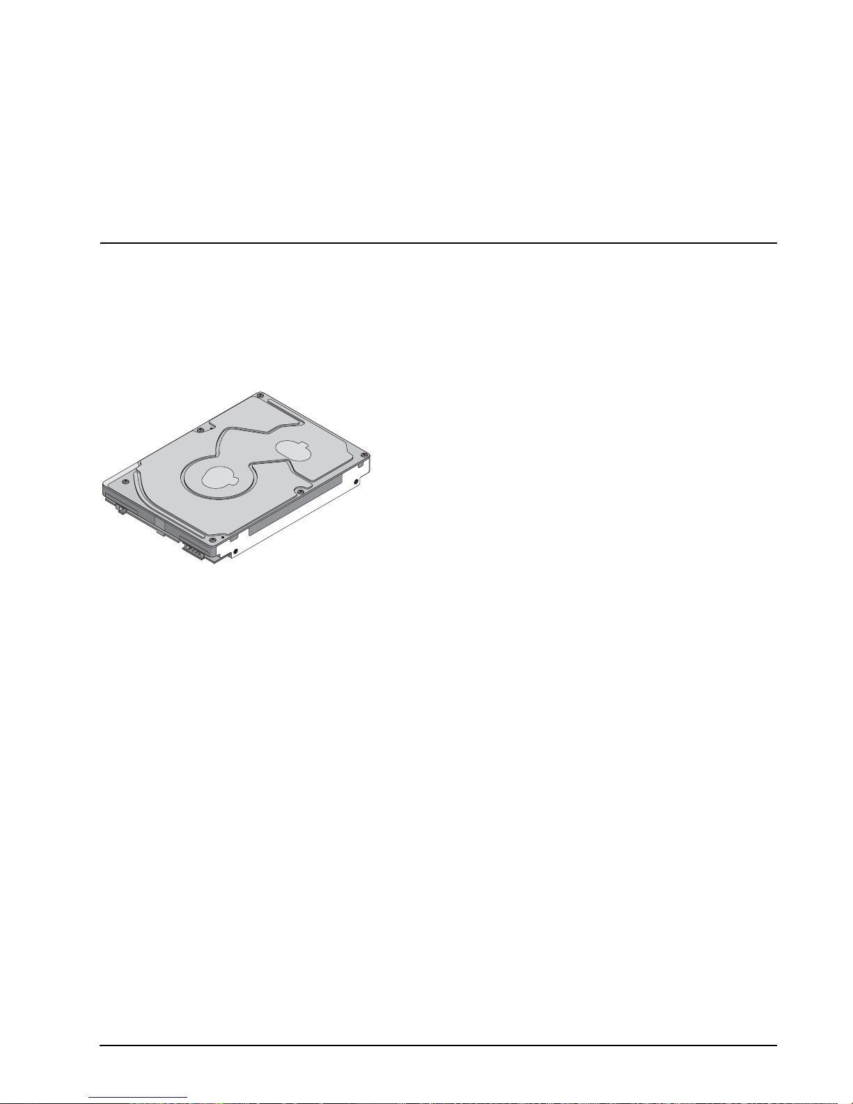
This manual describes Seagate Technology® LLC, Savvio® 10K.2 SAS (Serial Attached SCSI) disc drives.
Savvio drives sup port the SAS Protoc ol specifications to the extent describ ed in this manual. The SAS Inter-
face Manual (part number 100293071) describes t he general SAS characteri stics of this and other Se agate
SAS drives.
Figure 1. Savvio 10K.2 SAS disc drive
Savvio 10K.2 SAS Product Manual, Rev. B 1

2 Savvio 10K.2 SAS Product Manual, Rev. B

2.0 Applicable standards and reference documentation
The drive has been developed as a system peripheral to the highest standards of design and construction. The
drive depends on its host equip ment to provide adequate power and e nvironment for optimum performa nce
and compliance with appl icable i ndustry and g overnme ntal regulations. Special attention mu st be given in the
areas of safety, power distribution, s hielding, audible n oise control, and temperature regulat ion. In particular,
the drive must be securely mo unted to guar antee the spe cified pe rformance char acterist ics. Mountin g by bot
tom holes must meet the requirements of Section 8.3.
2.1 Standards
The Savvio family complies with Seagate standards as noted in the appropriate sections of this manual and the
Seagate SAS Interface Manual, part number 100293071.
The Savvio disc drive i s a UL recogni zed comp onent per UL1950 , CSA cert ified to CAN/ CSA C22.2 No. 95095, and VDE certified to VDE 0805 and EN60950.
2.1.1 Electromagnetic compatibility
The drive, as delivered , is designed for system integrati on and installation into a suitable encl osure prior to
use. The drive is supplied as a suba ssembly and is not subject to Sub part B of Part 15 of the FCC Rules and
Regulations nor the Radio Interference Regulations of the Canadian Department of Communications.
The design characteristics of the drive serve to minimize radiation when installed in an enclosure that provides
reasonable shielding. T he drive is ca pable of meeting the Cl ass B limits of the FCC Rules and Regulati ons of
the Canadian Department of C omm uni ca tio ns whe n p ro per ly pack ag ed; howe ve r, it is the user’s responsibil ity
to assure that the dri ve meets the approp riate EMI r equirements in thei r system. Sh ielded I/O c ables may be
required if the enclosure does not prov ide adequate shie lding. If the I/O cables are external to the enc losure,
shielded cables should be used, with the shields grounded to the enclosure and to the host controller.
-
2.1.1.1 Electromagnetic susceptibility
As a component a ssembly, the drive is not requ ired to meet any susc eptibi lity perfor mance requ irements. It is
the responsibilit y of those integrating the dr iv e wit hin the ir s y ste ms to perform those tests req uire d a nd des ig n
their system to ensure th at equipment operating in the same sy stem as the drive or external to the syste m
does not adversely affect the performance of the drive. See Tables
Savvio 10K.2 SAS Product Manual, Rev. B 3
12 and 13, DC power requirements.

2.1.2 Electromagnetic compliance
Seagate uses an inde pendent laborato ry to confirm comp liance with the directives/standa rds for CE Markin g
and C-Tick Marking. The drive was tested in a representative system for typical applications. The selected sys
tem represents the most popular characteristics for test platforms. The system configurations include:
• Typical current use microprocessor
• 3.5-inch floppy disc drive
• Keyboard
• Monitor/display
• Printer
• External modem
•Mouse
Although the test system with this Seagate model complies with the directives/standards, we cannot guarantee
that all systems will comply. The computer manufacturer or system integrator shall confirm EMC compliance
and provide the appropriate marking for their product.
Electromagnetic compliance for the European Union
If this model has the CE Marking it co mplies with the European Union requirements of the El ectromagnetic
Compatibility Directive 89 /336/EEC of 03 May 1989 as amend ed by Dir ective 92 /31/ EEC of 28 Apri l 1992 an d
Directive 93/68/EEC of 22 July 1993.
Australian C-Tick
-
If this model has th e C-Tick Marking it complies with the Austr alia/New Zeal and Standard AS/NZS3548 199 5
and meets the Electromagnet ic Compatibility (EMC) Framework requi rements of Australia’s Spectrum Man
agement Agency (SMA).
Korean MIC
If this model has the Korean Ministry of Information and Communication (MIC) logo, it complies with paragraph
1 of Article 11 of the Electromagnetic Compatibility (EMC) Control Regulation and meets the Electroma gnetic
Compatibility Framework requirements of the Radio Research Laborator y (RRL) Ministry of Information and
Communication Republic of Korea.
Taiwanese BSMI
If this model has t wo Chine se words meani ng “E MC ce rtifica tion” follo wed by an eig ht digi t identifi catio n n umber, as a Marking, it complies with Chinese National Standard (CNS) 13438 and meets the Electromagnetic
Compatibility (EMC) Fra mework requ irements of the Taiwanese Bureau of Standards, Metrology, and Inspec
tion (BSMI).
-
-
4 Savvio 10K.2 SAS Product Manual, Rev. B

2.1.3 European Union Restriction of Hazardous Substances (RoHS)
The European Union Restriction of Hazardous Substances (RoHS) Directive restricts the presence of chemical
substances, including Lead (Pb), in electronic products effective July 2006.
A number of parts and materials in Seagate products are procured from external suppliers. We rely on the representations of our suppl iers regarding the presence of RoHS substances in these parts and materials . Our
supplier contracts r equire compliance with our chem ical substance restrictions, a nd our suppliers document
their compliance with our requirements by providing material content declarations for all parts and materials for
the disc drives documented in this publication. Current supplier declarations include disclosure of the inclusion
of any RoHS-regulated substance in such parts or materials.
Seagate also has internal systems in place to ensure ongoing compliance with the RoHS Directive and all laws
and regulations which restrict chemical content in electronic products. These systems include standard operat
ing procedures that en sure that res tricted substa nces ar e not util ized in our m anufact uring ope ratio ns, la bora tory analytical validation testing, and an internal auditing process to ensure that all standard operating
procedures are complied with.
-
2.2 Reference documents
Savvio 10K.2 SAS Installation Guide
Seagate part number: 100384761
SAS Interface Manual
SCSI Commands Reference Manual
ANSI SAS Documents
ANSI Small Computer System Interface (SCSI) Documents
Specification for Acoustic Test Requirement and Procedures
Package Test Specification Seagate P/N 30190-001 (under 100 lb.)
Package Test Specification Seagate P/N 30191-001 (over 100 lb.)
In case of conflict between this document and any referenced document, this document takes precedence.
Seagate part number: 100293071
Seagate part number: 100293068
SFF-82232.5” Drive Form Factor with Serial Connector
SFF-8460HSS Backpla ne Design Gui deline s
SFF-8470Multi Lane Copper Connector
SFF-8482SAS Plug Connector
ANSI INCITS.xxx Serial Attached SCSI (SAS) Standard (T10/1562-D)
ISO/IEC 14776-xxxSCSI Architecure Model-3 (SAM-3) Standard (T10/1561-D)
ISO/IEC 14776-xxxSCSI Primary Commands-3 (SPC-3) Standard (T10/1416-D)
ISO/IEC 14776-xxxSCSI Block Commands-2 (SBC-2) Standard (T10/1417-D)
X3.270-1996(SCSI-3) Architecture Model
Seagate part number: 30553-001
Savvio 10K.2 SAS Product Manual, Rev. B 5

6 Savvio 10K.2 SAS Product Manual, Rev. B

3.0 General description
Savvio drives combine giant magnetoresistive (GMR) heads, partial response/maximum likelihood (PRML)
read channel electroni cs, e mbedded servo te chnol ogy, and a Serial Attached SCSI (SA S) inter face t o provid e
high performance, h igh c apaci ty d ata s tor age f or a v ari ety o f sy st ems inc l uding engineering workstatio ns , n et
work servers, mainframes, and supercomputers. The Serial Attached SCSI interface is designed to meet nextgeneration computing demands for performance, scalability, flexibility and high-density storage requirements.
Savvio drives are random acc ess storage d evices designe d to support the Serial Attached SCSI Protoc ol as
described in the ANSI spec ifications , this documen t, and the SAS Inte rface Manual ( part number 1002930 71)
which describes the general interface characteristics of this drive. Savv io drives are classified as intelligent
peripherals and provide level 2 confo rm ance ( hig hes t lev el) with the A NSI SC SI- 1 s tandard. Th e SA S connec
tors, cables and elec trical interface are com patible with Serial ATA (SATA), giving future us ers the choice of
populating their systems with either SAS or SATA hard disc drives. This allows you to continue to leverage your
existing investment in SCSI while gaining a 3Gb/s serial data transfer rate.
The head and disc assembly (HD A) is sealed at the factory. A ir recirculates within the HDA through a nonreplaceable filter to maintain a contamination-free HDA environment.
Note. Never disassemb le the HDA and do not attempt to se rvice items in the sealed enclosure (heads,
media, actuator, etc.) as this requires special facilities. The drive does not contain user-replaceable
parts. Opening the HDA for any reason voids your warranty.
Savvio drives use a de dica ted land ing zo ne at the inne rmost radi us of the media to elimi nate the possibi lity of
destroying or degrading data by landing in the data zone. The heads automatically go to the landing zone when
power is removed from the drive.
-
-
An automatic shipping lock prevents potential damage to the heads and discs that results from movement during shipping and h andling. The shipping lock disengages and th e head load process be gins when power is
applied to the drive.
Savvio drives decode track 0 location data from the servo data embedded on each surface to eliminate
mechanical transducer adjustments and related reliability concerns.
The drives also use a high-performance actuator assembly with a low-inertia, balanced, patented, straight arm
design that provides excellent performance with minimal power dissipation.
Savvio 10K.2 SAS Product Manual, Rev. B 7

3.1 Standard features
Savvio drives have the following standard features:
• Perpendicular recording technology
• 1.5 / 3 Gbit Serial Attached SCSI (SAS) in terface
• Integrated dual port SAS controller supporting the SCSI protocol
• Support for SAS expanders and fanout adapters
• Firmware downloadable using the SAS interface
• 128 - deep task set (queue)
• Supports up to 32 initiators
• Jumperless configuration.
• User-selectable logical block size (512 to 528 bytes per logical block) in any multiple of 4 bytes.
• Industry standard SFF 2.5-inch dimensions
• Programmable logical block reallocation scheme
• Flawed logical block reallocation at format time
• Programmable auto write and read reallocation
• Reallocation of defects on command (Post Format)
• ECC maximum burst correction length of 320 bits
• No preventive maintenance or adjustments required
• Dedicated head landing zone
• Embedded servo design
• Automatic shipping lock
• Self diagnostics performed when power is applied to the drive
• Zone bit recording (ZBR )
• Vertical, horizontal, or top down mounting
• Dynamic spindle brake
• 16 Mbyte data buffer (see Section 4.5).
• Drive Self Test (DST)
• Background Media Scan (BGMS)
• Idle Read After Write (IRAW)
•Power Save
3.2 Media description
The media used on the drive has an alumi num sub st rat e co ated with a thin fi lm magn eti c mater ia l, over coate d
with a proprietary protective layer for improved durability and environmental protection.
3.3 Performance
• Programmable multi-segmentable cache buffer
• 300 Mbytes/sec maximum instantaneous data transfers.
• 10k RPM spindle. Average latency = 3.0 msec
• Background processing of queue
• Supports start and stop commands (spindle stops spinning)
• Adaptive seek velocity; improved seek performance
8 Savvio 10K.2 SAS Product Manual, Rev. B
3.4 Reliability
• Annualized Failure Rate (AFR) or 0.55%
• Mean time between failures (MTBF) of 1,600,000 hours
• Balanced low mass rotary voice coil actuator
• Incorporates industry-standard Self-Monitoring Analysis and Reporting Technology (S.M.A.R.T.)
• 5-year warranty
3.5 Formatted capacities
Standard OEM models are formatted to 512 bytes per block. The block size is sele ctable at format time an d
must be a multiple of 4 by tes. Users having the necessary equi pment may modify the data block size before
issuing a format command and obtain different formatted capacities than those listed.
To provide a stable target capacity environment and at the same time provide users with flexibility if they
choose, Seagate recommends product planning in one of two modes:
1. Seagate designs spe ci fy c apacit y p oints at c ertain b loc k siz es that Seagate guarantee s curr ent and future
products will meet. We recommend custo mers use this capacity in their project pl anning, as it ensures a
stable operating point with backw ard and forward c ompatibi lity from gener ation to generati on. The curren t
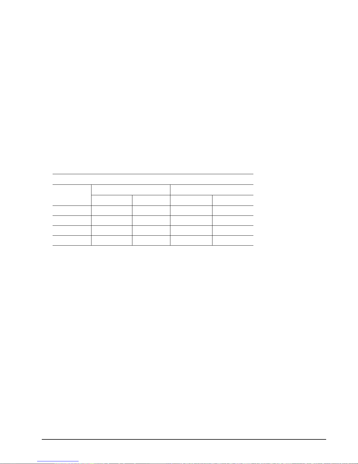
guaranteed operating points for this product are:
Capacity (Blocks)
ST9146802SS ST973402SS
Sector Size
Decimal Hex Decimal Hex
512 286749488 11177330h 143374744 88BB998h
520 280790192 10BC84B0h 140395096 85E4258h
524 275154368 106685C0h 137577184 83342E0h
528 272662936 10408198h 136331468 82040CCh
2. Seagate drives als o m ay be u se d at the max im um av ail ab le c apaci ty at a gi ve n bl ock si ze , but the excess
capacity above the gua rantee d l ev el wi ll v ar y between other drive fami lies an d f ro m g ene ra tio n to ge ner a
tion, depending on how eac h block size actually formats out for zo ne frequencies and splits over servo
bursts. This added capaci ty potent ial may range from 0.1 to 1.3 percent above th e guarant eed capacities
listed above. Us ing th e dr ives in th is mann er gi ves the ab so lute m aximu m capacity poten tial, but the user
must determine if the extra ca pacity potential is useful, or whether their assurance of backward and for
ward compatibility takes precedenc e.
3.6 Programmable drive capacity
Using the Mode Select command, the drive can change its capacity to something less than maximum. See the
Mode Select (6) parameter list table in the SAS Interface Manual, part numb er 100293 071. A valu e of zero in
the Number of Blocks field indicates that the drive will not change the capacity it is currently formatted to have.
A number other than z er o a nd less tha n t he maximum number of L BA s in the Num ber of B lo ck s fi eld c han ges
the tota l d rive capacity to the v al u e in t h e N umb er o f Bl o cks f ie l d. A v al u e gr ea t e r t h an t h e m ax im u m num be r of
LBAs is rounded down to the maximum capacity.
-
-
3.7 Factory-install ed accessories
OEM standard drives are shipped with the Savvio 10K.2 SAS Installation Guide (part number 100384761).
Savvio 10K.2 SAS Product Manual, Rev. B 9

3.8 Factory-install ed options
You may order the following items w hich are incorporated at th e manufacturing facility du ring production or
packaged before shipping. Some of the options available are (not an exhaustive list of possible options):
• Other capacities can be ordered depending on sparing scheme and sector size requested.
• Single-unit shipping pack. The drive is normally shipped in bulk packaging to provide maximum protec tion
against transit damage. Units shipped individually require additional protection as provided by the single unit
shipping pack. Users planning single unit distribution should specify this option.
• The Savvio 10K.2 SAS Installation Guide, part number 100384761, is us ually include d with each standar d
OEM drive shipped, but extra copies may be ordered.
• The Safety and Regulatory Agency Specifications, part number 75789512, is usually included with each
standard OEM drive shipped, but extra copies may be ordered.
10 Savvio 10K.2 SAS Product Manual, Rev. B

4.0 Performance characteristics
This section provides detailed information concerning performance-related characteristics and features of Savvio drives.
4.1 Internal drive characteri stics
ST9146802SS ST973402SS
Drive capacity 146.8 73.4 Gbytes (formatted, rounded off value)
Read/write data heads 4 2
Bytes per track 489,984 489,984 Bytes (average, rounded off values)
Bytes per surface 36,704 36,704 Mbytes (unformatted, rounded off value)
Tracks per surface (total) 75,373 75,373 Tracks (user accessible)
Tracks per inch 150,000 150,000 TPI (average)
Peak bits per inch 925,000 925,000 BPI
Areal density 135 135 Gbit/in
Internal data rate 660-1054 660-1054 Mbits/sec (variable with zone)
Disc rotation speed 10k 10k rpm
Avg rotational latency 3.0 3.0 msec
4.2 Seek performance characteristics
See Section 9.4.1, "SAS physical interface" on page 56 and the SAS Interface Manual (part number
100293071) for additional timing details.
2
4.2.1 Access time
Including controller overhead
(msec)
1, 2
Not including controller overhead
(msec)
Read Write Read Write
Average Typical
Single track Typical
Full stroke Typical
3,4
3,4
3,4
4.0 4.6 3.8 4.4
0.4 0.6 0.2 0.4
8.17 8.76 7.97 8.56
1. Execution time measured from receipt of the Command to the Response.
2. Assumes no errors and no sector has been relocated.
3. Typical access times are measured under nominal conditions of temperature, voltage, and horizontal orientation as
measured on a representative sample of driv es.
4. Access time = controller overhead + average seek time and applies to all data transfer commands.
Access to data = access time + latency time.
Data sheet data except full stroke which was Gen 2.0 data.
1,2
Savvio 10K.2 SAS Product Manual, Rev. B 11

4.2.2 Format command execution time for 512-byte sectors (minutes)
ST9146802SS ST973402SS
Maximum (with verify)
Maximum (without veri fy )
104 52
70 35
4.2.3 General performance characteristics
Minimum sect or interleave 1 to 1
Data buffer to/from disc media (one 512-byte logical block)* 82 to 132 MBytes/sec
Sustained transfer rate 55 to 89 Mbytes/sec
SAS Interface maximum instantaneous transfer rate 300 Mbytes/sec* per port
Logical block sizes Default is 512-byte data blocks
Variable 512 to 528 bytes per sector in evenly divisible by 4 number of bytes per
sector (512, 516, 520, 524, or 528). If n (number of bytes per sector is not divisi-
ble by 4, the next lowest number that is devisible by 4 will be used.
Read/write consecutiv e sectors on a track Yes
Flaw reallocation performance impact (for flaws reallocated at format time using the
spare sectors per sparing zone reallocation scheme.)
Average rotation al lat enc y 3.0 msec
*Assumes no errors and no relocated logical blocks. Rate measured from the start of the first logical block transfer to or
from the host.
(dual port = 600 Mbytes/sec*)
Negligible
12 Savvio 10K.2 SAS Product Manual, Rev. B

4.3 Start/stop time
The drive accepts the comma nds list ed in the SAS Inte rface Man ual less than 3 seconds after DC power has
been applied.
If the drive receives a NOTIFY (ENABLE SPINUP) primitive through either port and has not received a START
STOP UNIT command with the START bit equal to 0, the drive becomes ready for normal operations within 20
seconds (excluding the error recovery procedure).
If the drive receives a START STOP UNIT command with the START bit equal to 0 before receiving a NOTIFY
(ENABLE SPINUP) primitive, the drive waits for a START STOP UNIT command with the START bit equal to 1.
After receiving a START STOP UNIT command with the START bit equal to 1, the drive waits for a NOTI FY
(ENABLE SPINUP) primit ive. After receiving a NOTIFY (ENA BLE SPINUP) primitive throu gh either port, the
drive becomes ready for normal operations within 20 seconds (excluding the error recovery procedure).
If the drive receives a START STOP UNIT command with the START bit and IMMED bit equal to 1 and d oes
not receive a NOTIFY (ENABL E SPINUP) primitive within 5 seco nds, the drive fails the START STOP UNIT
command.
The START STOP UNIT command may be used to command the drive to stop the spindle. Stop time is 20 seconds (maximum) from re moval of DC power. SCSI stop time is 20 se conds. There is no power control swi tch
on the drive.
4.4 Prefetch/multi-segmented cache control
The drive provides a prefetch ( read look-ahead) and multi-se gmented cache control algori thms that in many
cases can enhan ce system performance. Cac he refers to the drive buffer stor age space when it is used in
cache operations . To select this feature, the host se nds the Mode Select com mand with the proper values in
the applicable bytes in page 08h. Prefetch and cache operations are independent features from the standpoint
that each is enabled and dis abled indepe ndently using the Mode Select c ommand; however, in actual opera
tion, the prefetch feature overlaps cache operation somewhat as described in sections 4.5.1 and 4.5.2.
-
All default cache and prefetch mode paramete r values (Mode Page 08 h) for standard OEM versions of this
drive family are given in Table
19.
4.5 Cache operation
Note. Refer to the SAS Interface Manual for more detail concerning the cache bits.
Of the 16 Mbytes physical buffer space in the drive, approximately 13,000 kbytes can be used as a cache. The
buffer is divided into logical segments from which data is read and to which data is written.
The drive keeps track of the logical block addresses of the data stor ed in each segment of the buffer. If the
cache is enabled (see RCD bit in the SAS Interface Manual
is retrieved from the buffer, if possible, before any disc access is initiated. If cache operation is not enabled, the
buffer is still used, but only as circular buffer segments during disc medium read operations (disregarding
Prefetch operation fo r the moment). That is, the dr iv e d oes not check in the buffer se gme nts for the requested
read data, but goes directly to the medium to retrieve it. The retrieved data merely passes through some buffer
segment on the way to the host. All data transfers to the host are in accordance with buffer-full ratio rules. See
the explanation provided with the information about Mode Page 02h (disconnect/reconnect control) in the SAS
Interface Manual.
The following is a simplified description of the prefetch/cache operation:
Case A—read command is received and all of the requested logical blocks are already in the cache:
1. Drive transfers the requested logical blocks to the initiator.
), data requested by the host with a read command
Savvio 10K.2 SAS Product Manual, Rev. B 13

Case B—A Read command r equests data, and at least one requested logical block is not in any segment of
the cache:
1. The drive fetches th e requested logical blocks f rom the dis c and trans fers them into a se gment, and then
from there to the host in accordance with the Mode Select Disconnect/Reconnect parameters, page 02h.
2. If the prefetch feature is enabled, refer to section 4.5.2 for operation from this point.
Each cache se gment is actually a s elf-contained circula r buffer whose length is an integer number of logical
blocks. The drive dynam ic ally cr ea tes and remo ves segments based on the workload. The wrap-around capa
bility of the individual segments greatly enhances the cache’s overall performance.
Note. The size of each s egment is not reported by Mode Sense command page 08h, bytes 14 and 15.
The value 0XFFFF is always reported regardless of the actual size of the segm ent . Se ndi ng a siz e
specification using the Mode Select command (byt es 14 and 15) does not set up a new segment
size. If the STRICT bit in Mode page 00h (byte 2, bit 1) is set to one , the driv e respon ds as it does
for any attempt to change an unchangeable parameter.
4.5.1 Caching write data
Write caching is a write operation by the drive th at mak es use of a drive buffer sto ra ge area where the data to
be written to the medium is stored while the drive performs the Write command.
If read caching is enabled (RCD=0), then data written to the medium is retained in the cache to be made available for future read cache hits. The s ame buffer space an d segme ntation is use d as set up for read func tions.
The buffer segmentation s cheme is set up or changed independently, having nothing to do with the state of
RCD. When a write command is issued, i f RCD=0, the cache is first checke d to see if any logical blocks tha t
are to be written are a lready stored in the cache f rom a previous read or write comman d. If there are, the
respective cache segments are cleared. The new data is cached for subsequent Read commands.
-
If the number of write data logical blocks exceed the size of the segment being written into, when the end of the
segment is reached, the data is written into the beginning of the same cache segment, overwriting the data that
was written there at the beginning of the operation; however, the drive does not overwrite data that has not yet
been written to the medium.
If write caching is enabled (WCE=1), then the drive may return Good status on a write command after the data
has been transferred into the cache, but befor e the data has been written to the medium. If an error oc curs
while writing the data to the medium, and Good status has already been returned, a deferred error will be gen
erated.
The Synchronize Cache command may be used to force the drive to write all cached write data to the medium.
Upon completion of a Synchronize Cache command, all data received from previous write commands will have
been written to the medium.
Table 19 shows the mode default settings for the drive.
4.5.2 Prefetch operation
If the Prefetch fea ture i s ena bl ed, data in co nti guo us lo gic al b lock s on t he d is c immediately beyond tha t whi ch
was requested by a Read c ommand are retrieved and stored in the buffer for immediate transfer from the
buffer to the host on subseque nt Read com mands that request t hose logica l block s (this is tr ue even if cache
operation is disabled). Though the prefetch operation uses the buffer as a cache, finding the requested data in
the buffer is a prefetch hit, not a cache operation hit.
To enable Prefet ch, use Mode Select page 08h , byte 12, bit 5 (Disable Read Ahead - DRA bit). DRA bit = 0
enables prefetch.
-
The drive does not use the Max Prefetch field (bytes 8 and 9) or the Prefetch Ceiling field (bytes 10 and 11).
14 Savvio 10K.2 SAS Product Manual, Rev. B

When prefetch (read look -ahead) is enabled ( enabled by DRA = 0), t he drive enables prefe tch of contiguous
blocks from the disc when it senses that a prefetch hit will likely occur. The drive disables prefetc h when it
decides that a prefetch hit is not likely to occur.
Savvio 10K.2 SAS Product Manual, Rev. B 15

16 Savvio 10K.2 SAS Product Manual, Rev. B

5.0 Reliability specifications
The following reli ability specifica tions assume co rrect host and drive operational interfa ce, including al l interface timings, power supply voltages, environmental requirements and drive mounting constraints.
Seek error rate: Less than 10 errors in 108 seeks
Read Error Rates
Recovered Data Less than 1 error in 1012 bits transferred (OEM default settings )
Unrecovered Data Less than 1 sector in 1016 bits transferred
Miscorrected Data Less than 1 sector in 1021 bits transferred
Interface error rate: Less than 1 error in 1012 bits transferred
Mean Time Between Failure (MTBF): 1,600,000 hours
Annualized Failure Rate (AFR): 0.55%
Preventive maintenance: None required
1. Error rate specified with automatic retries and data correction with ECC enabled and all flaws reallocated.
5.1 Error rates
The error rates stated in this manual assume the following:
• The drive is operated in accordance with this manual using DC p ower as defined in paragraph 6.2, "DC
power requirements."
• Errors caused by host system failures are excluded from error rate computations.
• Assume random data.
• Default OEM error recovery settin gs are applied. This includes AWRE, ARRE, full read retries, full write
retries and full retry time.
1
5.1.1 Recoverable Errors
Recovereable errors are those detected and corrected by the drive, and do not require user intervention.
Recoverable Data errors will use co rrection, although ECC on -the-fly is not c onsidered for purposes of recov-
ered error specifica tio ns.
Recovered Data error rate is determine d using read bits transfer red for recove rable errors occurring dur ing a
read, and using write bits transferred for recoverable errors occurring during a write.
5.1.2 Unrecoverable Erro rs
An unrecoverable data erro r is defined as a fail ure of the drive to rec over data from the me dia. These errors
occur due to head/medi a or write problems . Unrecoverable data errors are only detected du ring read opera
tions, but not caused by the r ead. If an unrec overable data erro r is detected, a ME DIUM ERROR (03 h) in the
Sense Key will be reported. Mul tipl e unrec ov erab le da ta errors resul tin g fro m the sa me c ause ar e tre ated as 1
error.
Savvio 10K.2 SAS Product Manual, Rev. B 17
-
 Loading...