

Seagate Nytro 5000 Product Manual
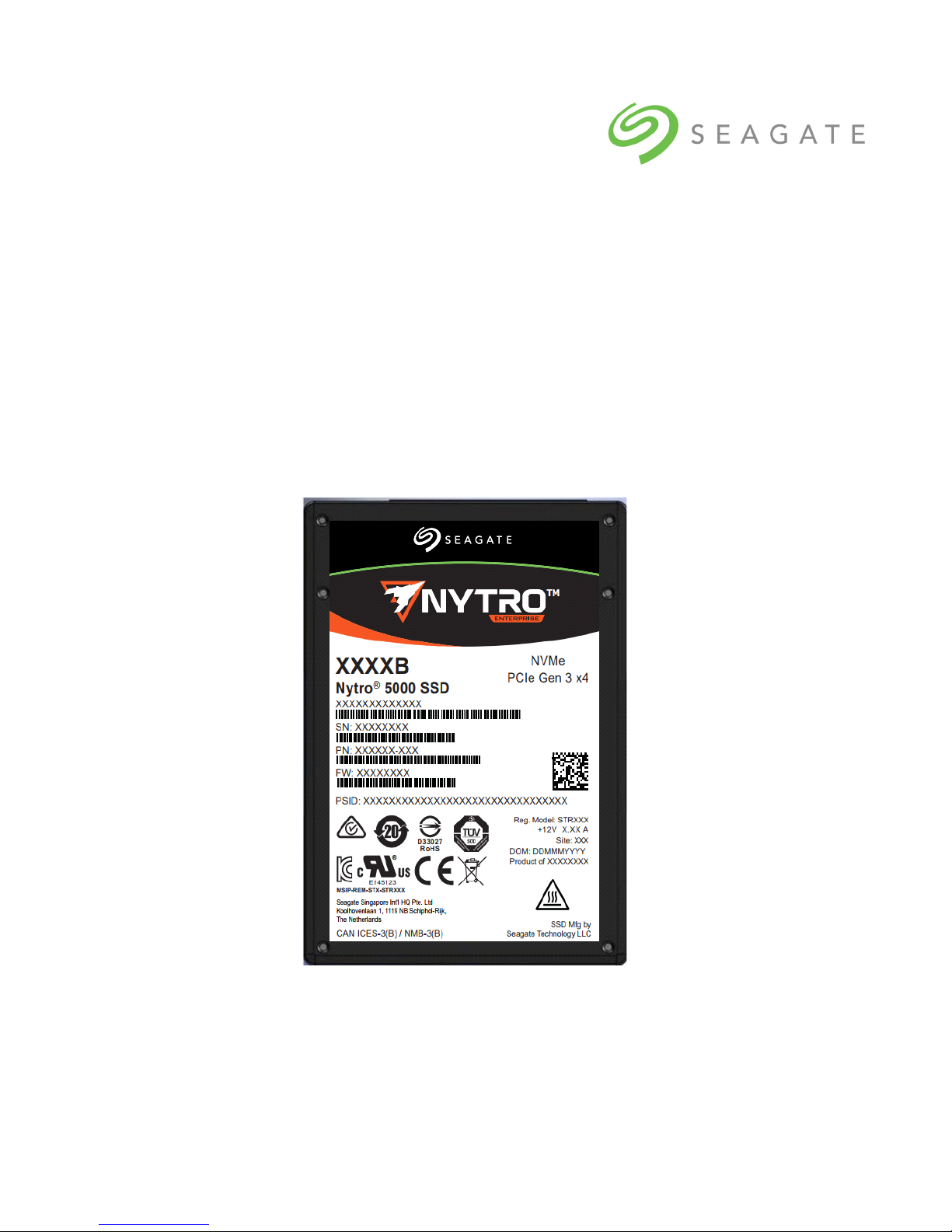
Seagate® Nytro® 5000
PCIe® Gen 3 x4 - NVMe 2.5” x 7mm
Product Manual
100810196, Rev.A
January 2018

Document Revision History
Revision Date Pages affected and description of change
Rev. A January 2018 Initial release.
© 2018 Seagate Technology LLC. All rights reserved.
Publication number:100810196, Rev. A, January 2018
Seagate, Seagate Technology and the Spiral logo are registered trademarks of Seagate Technology LLC in the
United States and/or other countries. Nytro and SeaTools are either trademarks or registered trademarks of Seagate
Technology LLC or one of its affiliated companies in the United States and/or other countries. The FIPS logo is a certification mark of NIST, which does not imply product endorsement by NIST, the U.S., or Canadian governments. All
other trademarks or registered trademarks are the property of their respective owners.
No part of this publication may be reproduced in any form without written permission of Seagate Technology LLC.
Call 877-PUB-TEK1 (877-782-8351) to request permission.
When referring to drive capacity, one gigabyte, or GB, equals one billion bytes and one terabyte, or TB, equals one
trillion bytes. Your computer’s operating system may use a different standard of measurement and report a lower
capacity. In addition, some of the listed capacity is used for formatting and other functions, and thus will not be
available for data storage. Actual quantities will vary based on various factors, including file size, file format, features and application software. Actual data rates may vary depending on operating environment and other factors.
The export or re-export of hardware or software containing encryption may be regulated by the U.S. Department of
Commerce, Bureau of Industry and Security (for more information, visit www.bis.doc.
import and use outside of the U.S. Seagate reserves the right to change, without notice, product offerings or specifications.
gov), and controlled for

Contents
1.0 Scope . . . . . . . . . . . . . . . . . . . . . . . . . . . . . . . . . . . . . . . . . . . . . . . . . . . . . . . . . . . . . . . . . . . . . . . . . . . . . . . . . . . . . . . 4
1.1 Models and Capacity . . . . . . . . . . . . . . . . . . . . . . . . . . . . . . . . . . . . . . . . . . . . . . . . . . . . . . . . . . . . . . . . . . . . . . . . . . 5
1.2 Performance . . . . . . . . . . . . . . . . . . . . . . . . . . . . . . . . . . . . . . . . . . . . . . . . . . . . . . . . . . . . . . . . . . . . . . . . . . . . . . . . . . 5
1.3 Power Consumption . . . . . . . . . . . . . . . . . . . . . . . . . . . . . . . . . . . . . . . . . . . . . . . . . . . . . . . . . . . . . . . . . . . . . . . . . . 5
1.4 Power Loss Data Protection. . . . . . . . . . . . . . . . . . . . . . . . . . . . . . . . . . . . . . . . . . . . . . . . . . . . . . . . . . . . . . . . . . . . 6
1.5 Out of Band Management (SMBus). . . . . . . . . . . . . . . . . . . . . . . . . . . . . . . . . . . . . . . . . . . . . . . . . . . . . . . . . . . . . 7
1.5.1 Vital Product Data (VPD) . . . . . . . . . . . . . . . . . . . . . . . . . . . . . . . . . . . . . . . . . . . . . . . . . . . . . . . . . . . .8
1.5.2 SMBus Electrical Parameters . . . . . . . . . . . . . . . . . . . . . . . . . . . . . . . . . . . . . . . . . . . . . . . . . . . . . . . . .9
1.6 Environmental Conditions . . . . . . . . . . . . . . . . . . . . . . . . . . . . . . . . . . . . . . . . . . . . . . . . . . . . . . . . . . . . . . . . . . . .9
1.6.1 Storage . . . . . . . . . . . . . . . . . . . . . . . . . . . . . . . . . . . . . . . . . . . . . . . . . . . . . . . . . . . . . . . . . . . . . . . . . . . .9
1.7 Reliability . . . . . . . . . . . . . . . . . . . . . . . . . . . . . . . . . . . . . . . . . . . . . . . . . . . . . . . . . . . . . . . . . . . . . . . . . . . . . . . . . . . .10
1.8 Endurance . . . . . . . . . . . . . . . . . . . . . . . . . . . . . . . . . . . . . . . . . . . . . . . . . . . . . . . . . . . . . . . . . . . . . . . . . . . . . . . . . . .11
2.0 Mechanical Information . . . . . . . . . . . . . . . . . . . . . . . . . . . . . . . . . . . . . . . . . . . . . . . . . . . . . . . . . . . . . . . . . . . . . 12
2.1 Mechanical Dimensions and Weight - 2.5” Models . . . . . . . . . . . . . . . . . . . . . . . . . . . . . . . . . . . . . . . . . . . . .12
2.2 Bottom Cover Stiffness/Deflection . . . . . . . . . . . . . . . . . . . . . . . . . . . . . . . . . . . . . . . . . . . . . . . . . . . . . . . . . . . .12
2.2.1 8639 Connector and Pin Descriptions. . . . . . . . . . . . . . . . . . . . . . . . . . . . . . . . . . . . . . . . . . . . . . .13
3.0 Interface requirements . . . . . . . . . . . . . . . . . . . . . . . . . . . . . . . . . . . . . . . . . . . . . . . . . . . . . . . . . . . . . . . . . . . . . . 16
3.1 PCIe features . . . . . . . . . . . . . . . . . . . . . . . . . . . . . . . . . . . . . . . . . . . . . . . . . . . . . . . . . . . . . . . . . . . . . . . . . . . . . . . . .16
3.2 Interface Commands Supported: . . . . . . . . . . . . . . . . . . . . . . . . . . . . . . . . . . . . . . . . . . . . . . . . . . . . . . . . . . . . .16
3.3 Log Page Support . . . . . . . . . . . . . . . . . . . . . . . . . . . . . . . . . . . . . . . . . . . . . . . . . . . . . . . . . . . . . . . . . . . . . . . . . . . .17
3.4 SMART Attributes . . . . . . . . . . . . . . . . . . . . . . . . . . . . . . . . . . . . . . . . . . . . . . . . . . . . . . . . . . . . . . . . . . . . . . . . . . . .18
4.0 Standards and Reference Documents. . . . . . . . . . . . . . . . . . . . . . . . . . . . . . . . . . . . . . . . . . . . . . . . . . . . . . . . . 20
4.1 Regulatory Model Numbers . . . . . . . . . . . . . . . . . . . . . . . . . . . . . . . . . . . . . . . . . . . . . . . . . . . . . . . . . . . . . . . . . .20
4.2 Standards . . . . . . . . . . . . . . . . . . . . . . . . . . . . . . . . . . . . . . . . . . . . . . . . . . . . . . . . . . . . . . . . . . . . . . . . . . . . . . . . . . . .20
4.3 Agency and Safety Certifications . . . . . . . . . . . . . . . . . . . . . . . . . . . . . . . . . . . . . . . . . . . . . . . . . . . . . . . . . . . . . .20
4.3.1 Safety Certification . . . . . . . . . . . . . . . . . . . . . . . . . . . . . . . . . . . . . . . . . . . . . . . . . . . . . . . . . . . . . . . . .20
4.3.2 Electromagnetic Compatibility . . . . . . . . . . . . . . . . . . . . . . . . . . . . . . . . . . . . . . . . . . . . . . . . . . . . .20
4.3.3 Electromagnetic susceptibility. . . . . . . . . . . . . . . . . . . . . . . . . . . . . . . . . . . . . . . . . . . . . . . . . . . . . .20
4.3.4 Electromagnetic compliance . . . . . . . . . . . . . . . . . . . . . . . . . . . . . . . . . . . . . . . . . . . . . . . . . . . . . . .20
4.3.5 European Union (EU) CE Marking Requirements. . . . . . . . . . . . . . . . . . . . . . . . . . . . . . . . . . . . .21
4.3.6 Australian RCM Compliance Mark . . . . . . . . . . . . . . . . . . . . . . . . . . . . . . . . . . . . . . . . . . . . . . . . . .21
4.3.7 Canada ICES-003 . . . . . . . . . . . . . . . . . . . . . . . . . . . . . . . . . . . . . . . . . . . . . . . . . . . . . . . . . . . . . . . . . . .21
4.3.8 South Korean Certification Mark . . . . . . . . . . . . . . . . . . . . . . . . . . . . . . . . . . . . . . . . . . . . . . . . . . . .21
4.3.9 Japan VCCI . . . . . . . . . . . . . . . . . . . . . . . . . . . . . . . . . . . . . . . . . . . . . . . . . . . . . . . . . . . . . . . . . . . . . . . .21
4.3.10 Morocco Commodity Mark . . . . . . . . . . . . . . . . . . . . . . . . . . . . . . . . . . . . . . . . . . . . . . . . . . . . . . . . .22
4.3.11 Taiwanese BSMI. . . . . . . . . . . . . . . . . . . . . . . . . . . . . . . . . . . . . . . . . . . . . . . . . . . . . . . . . . . . . . . . . . . .22
4.3.12 FCC verification . . . . . . . . . . . . . . . . . . . . . . . . . . . . . . . . . . . . . . . . . . . . . . . . . . . . . . . . . . . . . . . . . . . .22
4.4 Environmental protection . . . . . . . . . . . . . . . . . . . . . . . . . . . . . . . . . . . . . . . . . . . . . . . . . . . . . . . . . . . . . . . . . . . .23
4.4.1 European Union Restriction of Hazardous Substance Law . . . . . . . . . . . . . . . . . . . . . . . . . . .23
4.4.2 China Requirements —China RoHS 2 . . . . . . . . . . . . . . . . . . . . . . . . . . . . . . . . . . . . . . . . . . . . . . .24
4.4.3 Taiwan Requirements — Taiwan RoHS. . . . . . . . . . . . . . . . . . . . . . . . . . . . . . . . . . . . . . . . . . . . . .25
4.5 Reference Documents . . . . . . . . . . . . . . . . . . . . . . . . . . . . . . . . . . . . . . . . . . . . . . . . . . . . . . . . . . . . . . . . . . . . . . . .26
Seagate Nytro 5000 2.5” x 7mm SSD Product Manual, Rev. A 2

Seagate Technology Support Services
For Nytro Support, visit: http://www.seagate.com/support/by-product/ssd-and-pcie-flash/
For information regarding online support and services, visit: http://www.seagate.com/contacts/
Available services include:
Presales & Technical support
Global Support Services telephone numbers & business hours
Authorized Service Centers
For information regarding Warranty Support, visit: http://www.seagate.com/support/warranty-and-replacements/
For information regarding data recovery services, visit:
http://www.seagate.com/services-software/seagate-recovery-services/recover/
For Seagate OEM and Distribution partner and Seagate reseller portal, visit: http://www.seagate.com/partners
Seagate Nytro 5000 2.5” x 7mm SSD Product Manual, Rev. A 3

www.seagate.com
1.0 Scope
Seagate Nytro 5000 is a PCIe Gen 3 SSD, designed with the NVMe (Non-Volatile Memory Express) interface that delivers
leading performance, low latency, and world class reliability and endurance.
Scope
· Interface:
PCIe Gen 3 x4 NVMe SSD
Out of Band Management (SMBus)
management support
See Section 1.6 for details.
· Capacities:
800GB, 960GB, 1.6TB, 1.92TB.
See Section 1.2 for details.
· Components:
3D cMLC NAND Flash Memory
· Form Factor:
SFF 2.5 inch X 7mm
· Power
Lower power than current Enterprise class
products (12.5W)
Power Loss Data Protection (PLDP)
Hot Plug capable
Idle Power: 2.5 2.8W
Average Read/Write Power: 6.7W(without
Supercapacitor Learn cycle) 9.0W
See Section 1.4 and Section 1.5 for details.
·Shock
Operating/Non-Operating: 1500G @ 0.5ms
(Gs)
· Vibration
Operating: 3.08 G
(20-2000Hz)
· Certification
CE, BSMI, KCC, C-Tick,
FCC, IC, UL, TUV, CB
(7-800Hz), 16.3 G
RMS
RMS
·Reliability:
Mean Time Between Failure (MTBF):
2 million hours
Data Retention: 3 months @ 40°C
Sector Sizes: 4096 and 512 bytes
Non-recoverable Read Errors per bits read:
1 per 10E16
See Section 1.8 for details.
·Endurance
High Endurance models support up to 1.5
Drive Writes/day
Light Endurance models support up to 0.3
Drive Writes/day
See Section 1.9 for details.
· Temperature
Operating: 0 to 70°C
(as measured by SMART)
Non Operating: -40 to 85°C
See Section 1.7 for details.
·Airflow
See Section 1.7 for details.
·Performance
Varies by capacity and endurance. See
Section 1.3 for details.
·Security
Self encryptions available
·Warranty
5 years limited
·Product Compliance
RoHS
Seagate Nytro 2.5” x 7mm SSD Product Manual, Rev. A 4
www.seagate.com
1.1 Product Specifications
1.2 Models and Capacity
Table 1 Nytro 5000 2.5” 512 Sector Models and Capacities
Scope
Formatted
Capacity
Target Application: Read-Intensive Workloads
800GB XP800HE10002 XP800HE10012 1,562,824,368
1600GB XP1600HE10002 XP1600HE10012 3,125,627,568
Target Application: Mixed Workloads
960GB XP960LE10002 XP960LE10012 1,875,385,008
1920GB XP1920LE10002 XP1920LE10012 3,750,748,848
1.3 Performance
Table 2 Performance
Specification 800GB 1600GB 960GB 1.92TB
Sequential Read (MB/s)
Sustained
Sequential Write (MB/s)
Sustained, 128KB
Random Read (IOPS)
Sustained
Random Write (IOPS)
Sustained, 4KB QD64
Random 70/30 R/W (IOPS)
Sustained, 4KB QD64
, 128KB
, 4KB QD64
Standard
2.5” x 7 mm
Models
SED
2.5” x 7 mm
Models
2000 2000 2000 2000
1200 1200 1200 1200
245,000 245,000 245,000 245,000
60,000 67,000 25,000 28,000
130,000 150,000 75,000 100,000
512 bytes
LBA
Count
NOTE More information on Performance:
In certain performance metrics, performance of lower capacities are limited
based on the number of active dies.
IOMeter: Performance results are based on IOMeter. IOMeter is available at
http://sourceforge.net/projects/iometer/. IOMeter is licensed under the
Intel Open Source License and the GNU General Public License.
Response times: Typical response times are measured under nominal
conditions of temperature and voltage as measured on a representative
sample of drives.
Measurements: Measurements are performed on the drive after the
workload reaches steady state, including all background activities required
for normal operations.
1.4 Power Consumption
The 2.5" drive receives DC power (+12V) through the standard PCIe 8639 interface.
Seagate Nytro 2.5” x 7mm SSD Product Manual, Rev. A 5
www.seagate.com
Scope
NOTE
Table 3 DC Requirements
Supply Voltage 2.5”
Voltage Tolerances - nominal (%) 12V ± 10%
DC Ripple/Noise 450mV Max: 50-150KHz
Rise Time (Max*/Min)
*10% ~ 90% Nominal Voltage
Fall Time (Min) 100μs @ 1A max discharge
Minimum Off Time 150ms
Inrush Current (Max Peak) 2A for <2ms
Table 4 Power
Max Operating Power with Learn Cycle (W)
Power State 1 (W )
Power State 2 (W )
Power State 3 (W )
Here is more information on Power:
150mV Max: 10M-80M Hz
100ms* /0s (hot-pluggable)
Specification 2.5”
12.5
8.25
6.0
4.5
NVMe Autonomous Power States are not supported.
Typical power measurements are based on an average of drives tested
under nominal conditions.
Maximum power is defined as RMS over 100ms.
Reduced performance might be observed for power states below the Max
Operating Power.
1.5 Power Loss Data Protection
The drives implement an energy storage solution called Power Loss Data Protection. This circuit maintains power to the
NAND while the NAND is being programmed, even if power to the system is interrupted. Power loss data protection
ensures data integrity, and prevents loss of data and the resulting errors reporting back to the host.
Seagate Nytro 2.5” x 7mm SSD Product Manual, Rev. A 6

www.seagate.com
1.6 Out of Band Management (SMBus)
The provides sub-system management data to the host over the SMBus interface at 0x6A.
Table 5 Out of Band Management (SMBus) Protocol
Scope
Command
Code
0
Offset
(byte)
Length of Status: Indicates number of additional bytes to read before encountering PEC. This value should always
00
be 6 (06h) in implementations of this version of the spec.
Status Flags (SFLGS): This field indicates the status of the NVM subsystem.
SMBus Arbitration – Bit 7 is set ‘1’ after a SMBus block read is completed all the way to the stop bit without bus
contention and cleared to ‘0’ if a SMBus Send Byte FFh is received on this SMBus slave address.
Drive Not Ready – Bit 6 is set to ‘1’ when the subsystem cannot process NVMe management commands, and the rest of
the transmission may be invalid. If cleared to ‘0’, then the NVM subsystem is fully powered and ready to respond to management commands. This logic level intentionally identifies and prioritizes powered up and ready drives over their powered off neighbors on the same SMBus segment.
Drive Functional – Bit 5 is set to ‘1’ to indicate an NVM subsystem is functional. If cleared to ‘0’, then there is an
unrecoverable failure in the NVM subsystem and the rest of the transmission may be invalid.
01
Reset Not Required - Bit 4 is set to ‘1’ to indicate the NVM subsystem does not need a reset to resume normal
operation. If cleared to ‘0’ then the NVM subsystem has experienced an error that prevents continued normal
operation. A controller reset is required to resume normal operation.
Port 0 PCIe Link Active - Bit 3 is set to ‘1’ to indicate the first port’s PCIe link is up (i.e., the Data Link Control and
Management State Machine is in the DL_Active state). If cleared to ‘0’, then the PCIe link is down.
Port 1 PCIe Link Active - Bit 2 is set to ‘1’ to indicate the second port’s PCIe link is up. If cleared to ‘0’, then the second
port’s PCIe link is down or not present.
Bits 1-0 shall be set to ‘1’.
SMART Warnings: This field shall contain the Critical Warning field (byte 0) of the NVMe SMART / Health Information
log. Each bit in this field shall be inverted from the NVMe definition (i.e., the management interface shall indicate a
‘0’ value while the corresponding bit is ‘1’ in the log page). See the NVMe specification for bit definitions.
02
If there are multiple controllers in the NVM subsystem, the management endpoint shall combine the Critical Warning
field from every controller such that a bit in this field is:
Cleared to ‘0’ if any controller in the subsystem indicates a critical warning for that corresponding bit.
Set to ‘1’ if all controllers in the NVM subsystem do not indicate a critical warning for the corresponding bit.
Composite Temperature (CTemp): This field indicates the current temperature in degrees Celsius. If a temperature
value is reported, it should be the same temperature as the Composite Temperature from the SMART log of hottest controller in the NVM subsystem. The reported temperature range is vendor specific, and shall not exceed the
range -60 to +127°C. The 8 bit format of the data is shown below.
This field should not report a temperature when that is older than 5 seconds. If recent data is not available, the
NVMe management endpoint should indicate a value of 80h for this field.
Value Description
03
00h-7Eh Temperature is measured in degrees Celsius (0 to 126C)
7Fh 127C or higher
80h No temperature data or temperature data is more the 5 seconds old.
81h Temperature sensor failure
82h-C3h Reserved
C4 Temperature is -60C or lower
C5-FFh Temperature measured in degrees Celsius is represented in twos complement (-1 to -59C)
Percentage Drive Life Used (PDLU): Contains a vendor specific estimate of the percentage of NVM subsystem NVM life
used based on the actual usage and the manufacturer’s prediction of NVM life. If an NVM subsystem has multiple controllers the highest value is returned. A value of 100 indicates that the estimated endurance of the NVM in the NVM sub-
04
system has been consumed, but may not indicate an NVM subsystem failure. The value is allowed to exceed 100.
Percentages greater than 254 shall be represented as 255. This value should be updated once per power-on hour and
equal the Percentage Used value in the NVMe SMART Health Log Page.
06 : 05 Reserved: Shall be set to 0000h.
PEC: An 8 bit CRC calculated over the slave address, command code, second slave address and returned data.
07
Algorithm is in SMBus Specifications.
Description
Seagate Nytro 2.5” x 7mm SSD Product Manual, Rev. A 7
www.seagate.com
Table 5 Out of Band Management (SMBus) Protocol (continued)
Scope
Command
Code
8
32+ 255 : 32
Offset
(byte)
08
10 : 09
30 : 11
31
Length of identification: Indicates number of additional bytes to read before encountering PEC.
This value should always be 22 (16h) in implementations of this version of the spec.
Vendor ID: The 2 byte vendor ID, assigned by the PCI SIG. Should match VID in the Identify Controller command
response. MSB is transmitted first.
Serial Number: 20 characters that match the serial number in the NVMe Identify Controller command response.
First character is transmitted first.
PEC: An 8 bit CRC calculated over the slave address, command code, second slave address and returned data.
Algorithm is in SMBus Specifications.
Vendor Specific: This data structure shall not exceed the maximum read length of 255 specified in the SMBus
version 3 specification. Preferably length is not greater than 32 for compatibility with SMBus 2.0, additional blocks
shall be on 8 byte boundaries.
NOTE You can find a description of sub-system management data to the host over the
SMBus interface in the NVM Expresss Management Interface 1.0.
1.6.1 Vital Product Data (VPD)
The drives access a Vital Product Data (VPD) EEPROM page as listed below through address 0xA6.
This requires 3.3V Auxiliary voltage.
Table 6 VPD Structure
Address Function Typ e
Size
(B)
Description
Default
Size
Description
0 Class Code RO 3 Vendor Device type and programming interface
3
5 20 Vendor Serial Number (vendor unique)
25 40 Vendor Model Number (ASCII string)
65
66 Maximum Link Width
67
68 Maximum Link Width
69
70 0 Reserved
71 0 Reserved
72
73 0 Reserved
74 0 Reserved
75
PCIe Port 0 Capabilities RO 2 Vendor
PCIe Port 1 Capabilities RO 2 Vendor
Initial Power Requirements RO 3
Maximum Power Requirements RO 3
Capability List Pointer RO 2 Vendor
NOTE
ID RO
Initial and Maximum Power requirements are not supported.
2 Vendor PCI-SIG Vendor ID
Maximum Link Speed
Maximum Link Speed
Vendor 12V power rail initial power requirement (W)
Vendor 12V power rail initial power requirement (W)
16-bit address pointer to start of capability
list (zero means no capability list)
Seagate Nytro 2.5” x 7mm SSD Product Manual, Rev. A 8
 Loading...