

Page 1

2021
Lyve Rack R1 Installation
Guide
P/N: 1104167-01
Revision: J
January 2021
Page 2

Notices
© 2020 - 2021 Seagate Cloud Systems, Inc. All rights reserved. Seagate, Seagate Technology and the
Spiral logo are registered trademarks of Seagate Technology LLC in the United States and/or other
countries. All other trademarks or registered trademarks are the property of their respective owners.
When referring to drive capacity, one gigabyte, or GB, equals one billion bytes and one terabyte, or TB,
equals one trillion bytes. Your computer’s operating system may use a different standard of
measurement and report a lower capacity. In addition, some of the listed capacity is used for formatting
and other functions, and thus will not be available for data storage. Actual data rates may vary
depending on operating environment and other factors. The export or re-export of Seagate hardware or
software is regulated by the U.S. Department of Commerce, Bureau of Industry and Security (for more
information, visit www.bis.doc.gov), and may be controlled for export, import and use in other
countries. All coded instruction and program statements contained herein is, and remains copyrighted
works and confidential proprietary information of Seagate Technology LLC or its affiliates. Any use,
derivation, dissemination, reproduction, or any attempt to modify, reproduce, distribute, disclose
copyrighted material of Seagate Technology LLC, for any reason, in any manner, medium, or form, in
whole or in part, if not expressly authorized, is strictly prohibited. Seagate reserves the right to change,
without notice, product offerings or specifications.
Page 3

Table of Contents
1 | Welcome to Seagate Lyve Rack R1! ........................................................................................................ 3
2 | What’s in the box? .................................................................................................................................. 4
3 | Safety and compliance ............................................................................................................................ 7
3.1 | Safe handling .................................................................................................................................... 7
3.2 | Safety ................................................................................................................................................ 7
4 | Support .................................................................................................................................................... 9
Documentation ......................................................................................................................................... 9
Seagate documentation ............................................................................................................................ 9
Supermicro server documentation ........................................................................................................... 9
Seagate support ........................................................................................................................................ 9
5 | Hardware installation ............................................................................................................................ 10
5.1 | Hardware installation sequence .................................................................................................... 10
5.2 | Hardware installation overview ..................................................................................................... 10
5.3 | 5U84 storage enclosure installation .............................................................................................. 12
5.4 | Server installation .......................................................................................................................... 14
5.5 | Network switch and other components ........................................................................................ 15
6 | Cable connection ................................................................................................................................... 16
6.1 | Cables ............................................................................................................................................. 16
6.2 | Recommended cabling sequence .................................................................................................. 18
6.3 | Connecting power cables to storage enclosure and servers ......................................................... 23
7 | Pre-boarding Lyve Rack R1 .................................................................................................................... 25
7.1 | General requirements for network configuration ......................................................................... 25
7.1.1 | Data Network connectivity for Lyve Rack R1 .......................................................................... 30
7.2 | Management network ................................................................................................................... 31
7.3 | High-speed data network ............................................................................................................... 32
7.4 | Static virtual IPs .............................................................................................................................. 32
7.5 | Network address allocation and reservation summary ................................................................. 33
8 | Turn ON power ...................................................................................................................................... 34
8.1 | Switch ON storage enclosure ......................................................................................................... 34
8.2 | Switch ON server ............................................................................................................................ 35
9 | Cluster initialization ............................................................................................................................... 38
9.1 | Prerequisites .................................................................................................................................. 38
Page 4

Lyve Rack R1 Installation Guide
10 | Onboarding Lyve Rack R1 .................................................................................................................... 41
10.1 | Configuring admin user ................................................................................................................ 41
10.2 | Uploading SSL certificate .............................................................................................................. 42
10.3 | Configuring DNS resolver settings ................................................................................................ 42
10.4 | Configuring network time protocol .............................................................................................. 42
10.5 | Configuring notifications .............................................................................................................. 42
10.6 | Verifying onboarding configuration ............................................................................................. 43
Appendix ..................................................................................................................................................... 44
Page 5

List of Figures
Figure 1: Seagate Lyve Rack package ............................................................................................................ 4
Figure 2: Lyve Rack system ......................................................................................................................... 10
Figure 3: Mounting the system into a rack (only left rail is shown for clarity) ........................................... 11
Figure 4: Front view of the 5U84 storage enclosure .................................................................................. 12
Figure 5: Rear view of 5U84 storage enclosure .......................................................................................... 12
Figure 6: Front of 5U84 storage enclosure anti-tamper locks and drawer latches .................................... 13
Figure 7: Populated the top drawer ............................................................................................................ 14
Figure 8: Populated the bottom drawer ..................................................................................................... 14
Figure 9: 6019P Server cable connections (excluding power supply)......................................................... 19
Figure 10: 6019U Server cable connections (excluding power supply) ...................................................... 20
Figure 11: Storage enclosure power connections ...................................................................................... 23
Figure 12: 6019P Server power connections .............................................................................................. 24
Figure 13: 6019U Server power connections .............................................................................................. 24
Figure 14: 6019P Server networking subnet requirements ........................................................................ 26
Figure 15: 6019U Server networking subnet requirements ....................................................................... 27
Figure 16: 5U84 storage enclosure PSU. Power switch 'O' = OFF; 'I' = ON ................................................. 34
Figure 17: Ops panel - Only the Power ON LED should be lit. .................................................................... 35
Figure 18: Drawer LED panels ..................................................................................................................... 35
Figure 19: Different components of the server control panel present at the front ................................... 35
Figure 20: Server when switched ON .......................................................................................................... 37
Page 6

Lyve Rack R1 Installation Guide
1
List of Tables
Table 1: Documents for understanding detailed installation procedure ..................................................... 3
Table 2: Product package contents ............................................................................................................... 5
Table 3: Set of deliverables that are delivered to the customer .................................................................. 5
Table 4: Lyve Rack System cables ............................................................................................................... 16
Table 5: Cables supplied with 5U84 storage enclosure .............................................................................. 18
Table 6: Cables supplied with servers ......................................................................................................... 18
Table 7: Lyve Rack connection components ............................................................................................... 20
Table 8: List of Open ports .......................................................................................................................... 29
Table 9: Server control panel component description ............................................................................... 35
Table 10: Different status of information LED of the server....................................................................... 36
Table 11: Supported and unsupported email configurations ..................................................................... 43
Page 7

Lyve Rack R1 Installation Guide
2
Revision History
Revision History
Description
Release month and year
J
Release
January 2021
Page 8
Lyve Rack R1 Installation Guide
3
1 | Welcome to Seagate Lyve Rack
R1!
Welcome to Lyve Rack R1! This document provides high-level information on how to install Lyve Rack.
For more detailed information, refer to the documents in Table 1: Documents for understanding
detailed installation procedure. To access the documents, scan the QR code with your smartphone or
tablet.
Table 1: Documents for understanding detailed installation procedure
Guide
URL
Seagate
5005/4005/3005
Series Hardware
Installation and
Maintenance
Guide (For 5U84
storage enclosure
reference)
https://www.seagate.com/support/lyve-rack/maintenance-guide/
Supermicro
Server Hardware
Installation and
Maintenance
Guide
1. Go to https://www.supermicro.com/
2. Hover over Support, and then click Manuals.
3. In the Select Category dropdown list, select SuperServers.
4. In the Select Product Type dropdown list, select 1U.
5. Click Submit Request.
6. Locate and refer to the documents for 1U servers – SYS-6019P-WTR or SYS-
6019U-TRT.
Page 9
Lyve Rack R1 Installation Guide
4
2 | What’s in the box?
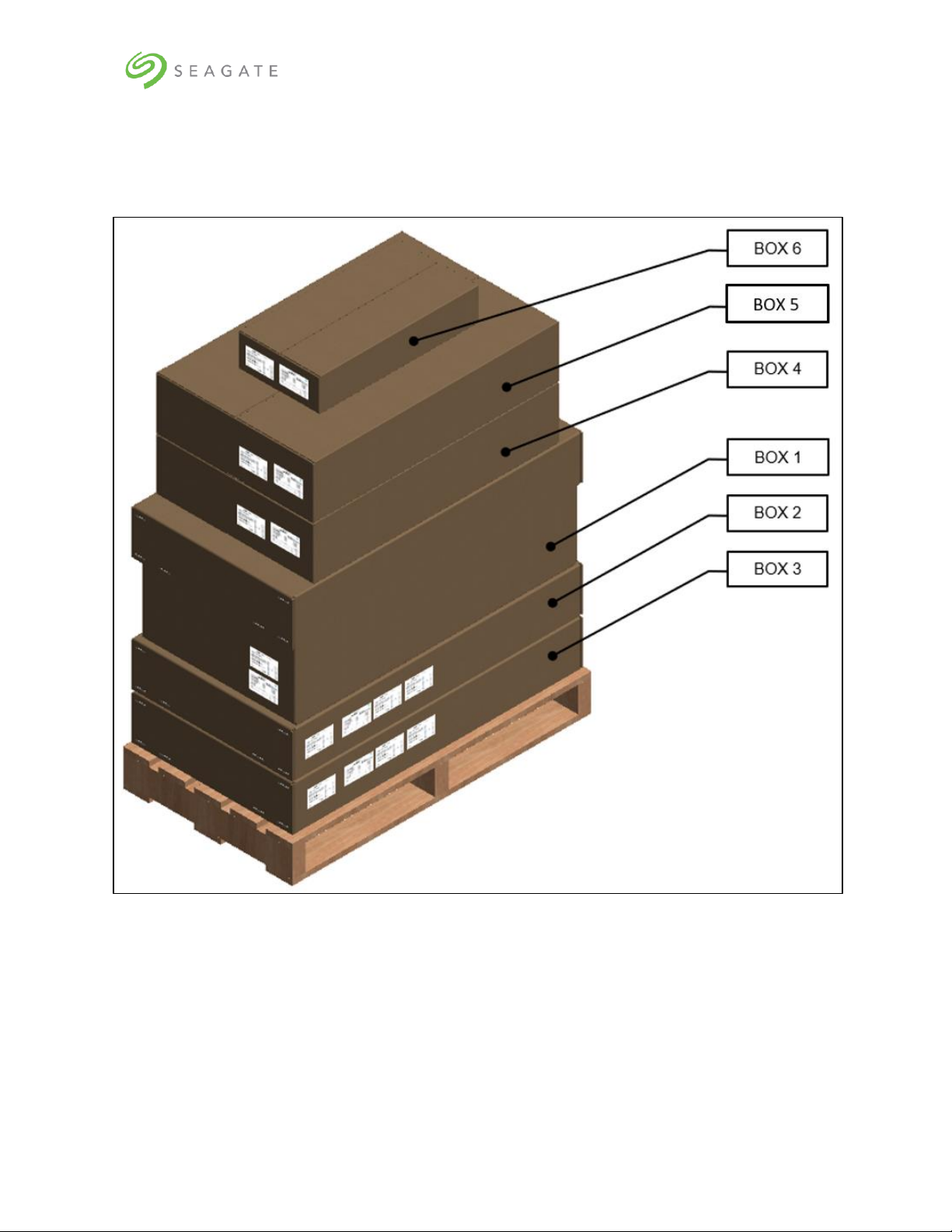
You will receive the Seagate Lyve Rack system as a collection of component elements packaged on a
single pallet.
Figure 1: Seagate Lyve Rack package
Each carton shows a bundle label associating it with a specific appliance component set.
Page 10
Lyve Rack R1 Installation Guide
5
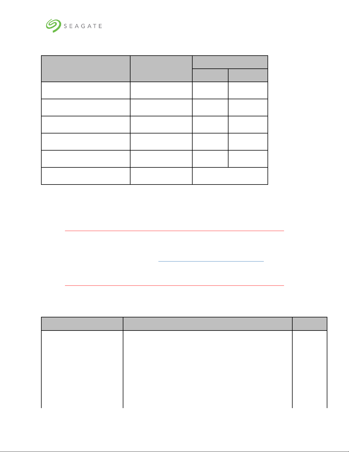
Table 2: Product package contents
Carton
Box number
Weight in kg/lb
Packaging
Gross
5U84 System Pack
Box 1 of 6
40/88.18
256/564.38
DDIC* 42-pack
Box 2 of 6
1.8/3.96
75.6/165.34
DDIC* 42-pack
Box 3 of 6
1.8/3.96
75.6/165.34
Server pack (Secondary server)
Box 4 of 6
11.8/26.01
18.6/41
Server pack (Primary server)
Box 5 of 6
11.8/26.01
18.6/41
Accessories Kit
Box 6 of 6
4.5/10
*DDIC is Disk Drive in Carrier.
Since the HDDs included with the appliance are pre-configured at the factory for use with the specific
5U84 storage enclosure with which they are shipped, it is important to ensure that the 42-pack
cartons (Box 2 and Box 3 as mentioned in Table 2) are not mixed up with any other 42-pack cartons
received at your location.
Important
It is also important that the drives are arranged in ascending order for the top and
bottom tray as described in section 5.3 | 5U84 storage enclosure installation. In any
future scenarios where multiple or all the drives are unplugged, this requirement
must also be followed.
Table 3: Set of deliverables that are delivered to the customer describes the set of deliverables that are
delivered to you making up the Lyve Rack system.
Table 3: Set of deliverables that are delivered to the customer
Item
Description
Qty
Accessories Kit
Contains cables and documentation
a) SFF-8644 SAS cable
a) 8
b) 100GbE to 100GbE (QSFP28 to QSFP28) Direct Attach
Passive Copper Cable Ethernet Black 30AWG CA-N
b) 1
c) C13-C14 power cord
c) 4
d) Documentation reference sheet
d) 1
Page 11

Lyve Rack R1 Installation Guide
6
Item
Description
Qty
e) Information Sheet
e) 1
f) Notice
f) 1
Supermicro SYS-6019P-WTR
OR
Supermicro SYS-6019U-TRT
1U Server
2
Seagate RSS RBOD product:
D5565X000000DA
5U84x HDD storage enclosure
1
Seagate HDDs:
PFRUKTXDXE013-42 - 14TB
PFRUKTXDXE022-42 - 16TB
1104413-01 - 18TB
Seagate 14TB, 16TB, or 18TB HDDs in carriers
84
Page 12

Lyve Rack R1 Installation Guide
7
3 | Safety and compliance
3.1 | Safe handling
• An unpopulated enclosure can weigh up to 46kg (101lb). Use appropriate lifting methods.
• A fully populated enclosure weighs 135kg (298lb). You must lift the enclosure when the
drawers are empty and latched closed. Do not attempt to lift the enclosure when populated
with drives.
• When closing the drawers, do so firmly, ensuring the latches are engaged.
• Please use belt straps to lift the enclosure out of the box.
• Do not try to lift the enclosure by yourself.
• Use appropriate lifting methods. Before lifting the enclosure:
o Remove DDICs drive carriers from drawers and verify the drawers are closed and firmly
locked.
o Use a minimum of three people to lift the enclosure using the lifting straps provided.
o Avoid lifting the enclosure using the handles on any of the CRUs because they are not
designed to take the weight. Lift from underneath the main enclosure.
• Observe the lifting hazard label affixed to the storage enclosure.
3.2 | Safety
• This equipment is for installation in a Restricted Access Location only.
A restricted access location is where:
o Access can only be gained by service persons or users who have been fully instructed on
the reasons for the restrictions applied to the location and on any precautions that must
be taken.
o Access is through the use of a tool or lock and key, or other means of security, and is
controlled by the authority responsible for the location.
Caution
If this equipment is used in a manner not specified by the manufacturer, the
manufacturer warranty provided by the equipment may be impaired.
• All drives and rear modules are part of the 5U84 storage enclosure and must only be removed
when a replacement can be immediately added. The system must not be run without all rear
modules in place.
• Permanently unplug the enclosure before you move it or if you think that it has become
damaged in any way.
• Always remove the drives, Power Supply Units (PSUs), controllers, and System fans to
minimize weight before you move the enclosure.
• A safe electrical ground connection must be provided to the power supply cords.
Important
The enclosure MUST be grounded before applying power.
Page 13

Lyve Rack R1 Installation Guide
8
• The plug on the power supply cord is used as the main disconnect device. Ensure that the
socket outlets are located near the equipment and are easily accessible.
• When powered by multiple AC sources, disconnect all power supplies for complete isolation.
• In order to comply with applicable safety, emission, and thermal requirements no covers
should be removed, and rear panel must be populated with plug-in modules.
• The power connection should always be disconnected prior to insertion or removal of a PSU
from the enclosure.
• Do not attempt to disassemble the rear sub-chassis from the enclosure.
• Provide a suitable power source with electrical overload protection to meet the requirements
laid down in the technical specification.
• If any component of the product fails, consult Seagate support.
• For North American use, each branch circuit must be rated for 20A.
• The equipment is suitable for connection to an IT power system (Norway), when mounted in a
Restricted Access Location where equipotential bonding has been applied by a service person.
Important
The optional RJ45 socket on the controller module is for Ethernet connection only
and must not be connected to a telecommunications network.
Caution
• Operating temperatures inside the enclosure drawers can reach up to 60°C. Be careful
while opening drawers and removing drive carriers.
• Double pole/neutral fusing in PSUs.
• Risk of explosion if the battery within the controller is replaced with an incorrect
type. Dispose used batteries according to the instructions. There are no user
serviceable parts within the controller.
• Due to product acoustics ear protection must be worn during prolonged exposure to
the product in operation.
• To prevent over-turning, drawer interlocks stop users from opening both drawers at
the same time. Do not attempt to force open a drawer when the other drawer is
already open.
Page 14

Lyve Rack R1 Installation Guide
9
4 | Support
Documentation
Seagate documentation
The following documents are available to explain how to install and use the Lyve Rack product.
• Lyve Rack R1 Notice: Read This First (refer to the Accessory kit)
• Lyve Rack R1 Documentation Reference Sheet (refer to the Accessory kit)
• Lyve Rack R1 Information Sheet (refer to the Accessory kit)
• Lyve Rack R1 Installation Checklist (visit www.seagate.com/support/lyve-rack)
• Lyve Rack R1 Installation Guide (visit www.seagate.com/support/lyve-rack)
• Lyve Rack R1 User Guide (visit www.seagate.com/support/lyve-rack)
• Lyve Rack R1 API Guide (visit www.seagate.com/support/lyve-rack)
• Lyve Rack R1 Troubleshooting Guide (visit www.seagate.com/support/lyve-rack)
• 5005/4005/3005 Series Hardware Installation & Maintenance Guide (visit
www.seagate.com/support/lyve-rack)
Supermicro server documentation
1. Go to https://www.supermicro.com/
2. Hover over Support, and then click Manuals.
3. In the Select Category dropdown list, select SuperServers.
4. In the Select Product Type dropdown list, select 1U.
5. Click Submit Request.
6. Locate and refer to the documents for 1U servers – SYS-6019P-WTR or SYS-6019U-TRT.
Seagate support
Visit Lyve Rack R1 support page at www.seagate.com/support/lyve-rack.
Page 15
Lyve Rack R1 Installation Guide
10
5 | Hardware installation
5.1 | Hardware installation sequence
You must first install the rail kits, and then the remaining hardware from bottom to top.
1. Install 5U84 storage enclosure rail kit, and server rail kits in the rack.
2. Install 5U84 storage enclosure in the rack.
3. Install the Supermicro server B in the 1U rack slot present above 5U84.
4. Install the Supermicro server A in the 1U rack slot present above server B.
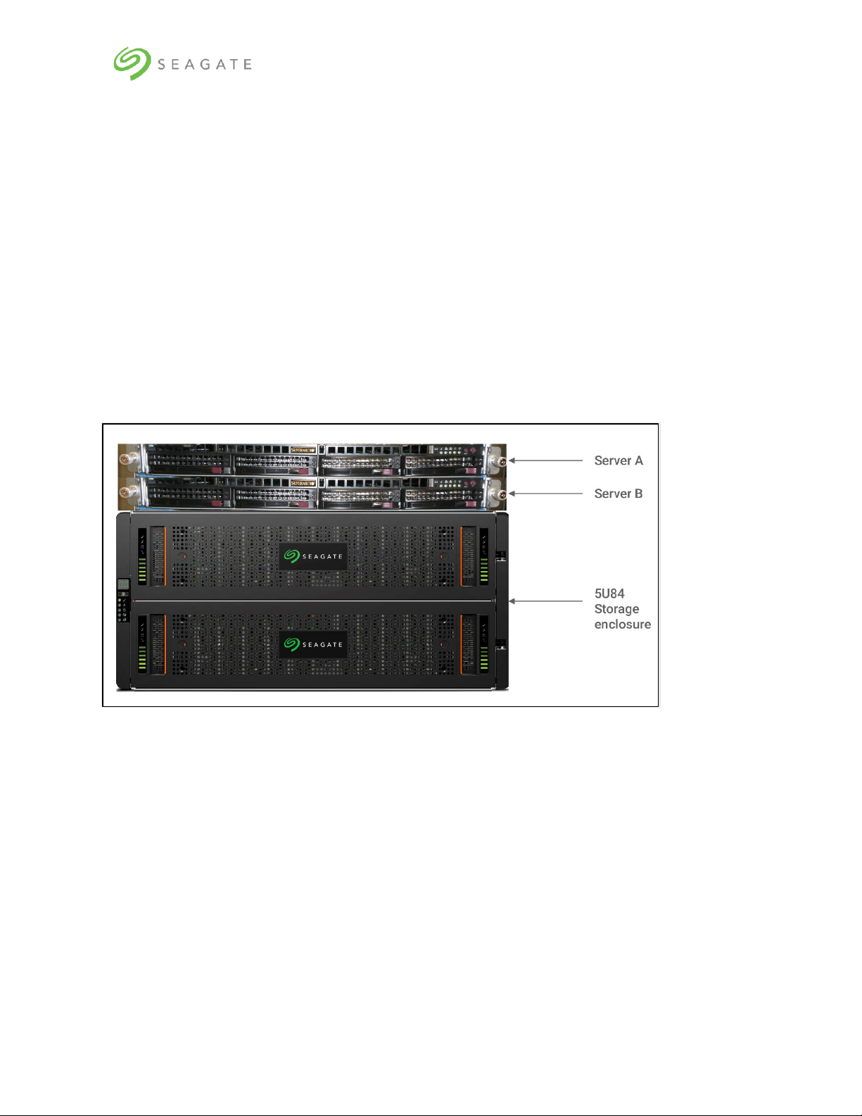
It is recommended to install Lyve Rack system in a rack such that the two 1U servers are located
directly above the 5U84 storage enclosure. The upper server is designated as server A and the server
closest to the 5U84 storage enclosure is designated as server B. Figure 2 shows the completed
installation of the Lyve Rack system.
Figure 2: Lyve Rack system
5.2 | Hardware installation overview
The Lyve Rack solution includes the 5U84 enclosure. This section briefly introduces some of the
elements.
Figure 3, Figure 4, and Figure 5 describe the rail kit, front view, and rear view of the 5U84 with all
modules installed.
Page 16
Lyve Rack R1 Installation Guide
11
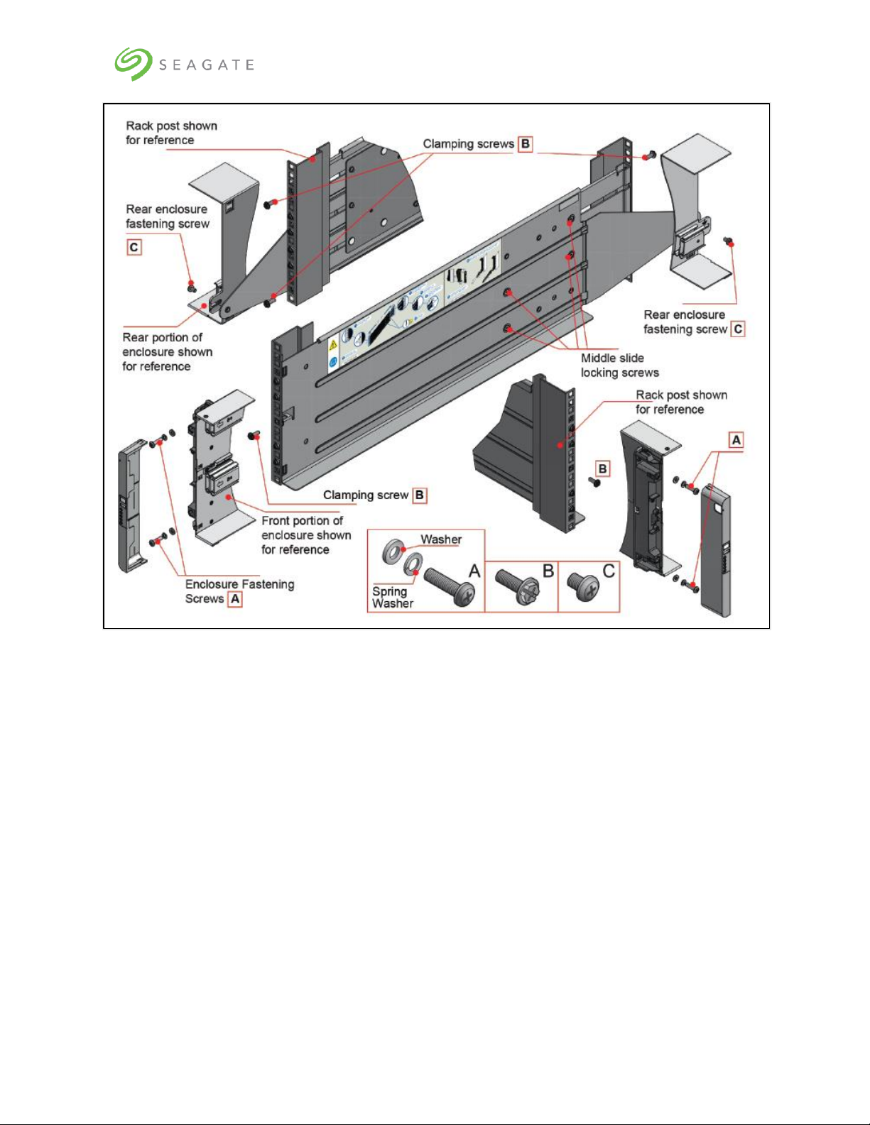
Figure 3: Mounting the system into a rack (only left rail is shown for clarity)
Figure 3 shows left rail kit placed in a rack in an alignment with its various fasteners, along with 5U84
enclosure and its front locking bracket. For clarity, we have not shown the entire 5U84 enclosure in
the figure.
Complete left rail kit can be seen at the center of this figure. Whereas, top left and bottom right
portion of the figure shows the front and rear of the central left rail illustration from a different angle.
Top left of the figure shows rear rack post along with partially visible left back rail and rear right
portion of the storage enclosure.
Bottom right of the figure shows front rack post along with partially visible left front rail and front left
potion of the storage enclosure along with the Locking bracket.
Two Clamping screws (B) at the back and one Clamping screw (B) at the front are used to fix the rail
kit with the rack post. Whereas, two Enclosure Fastening screws (A) at the front and one Rear
Enclosure Fastening screw (C) at the back are used to fix the 5U84 enclosure with the rail kit at the
front and the back, respectively.
Page 17
Lyve Rack R1 Installation Guide
12
Figure 4: Front view of the 5U84 storage enclosure
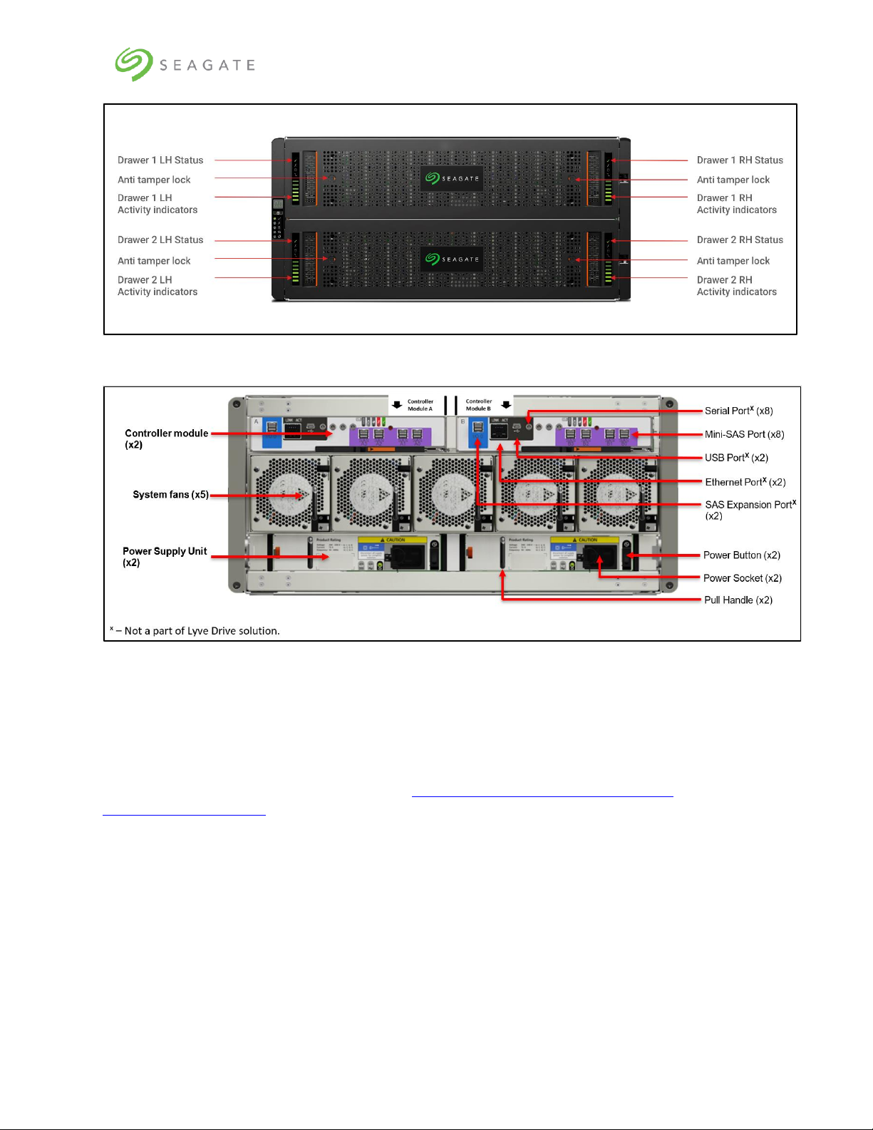
Figure 5: Rear view of 5U84 storage enclosure
5.3 | 5U84 storage enclosure installation
Follow instructions in the CHAPTER 3 INSTALLATION OF THE SEAGATE 5005/4005/3005 SERIES HARDWARE
INSTALLATION AND MAINTENANCE GUIDE available at https://www.seagate.com/support/lyve-
rack/maintenance-guide/
Refer to the following specific sections in the Hardware Installation and Maintenance guide that when
followed, shall complete the hardware installation of the 5U84.
• CHAPTER 3 INSTALLATION → UNPACKING THE ENCLOSURE
• CHAPTER 3 INSTALLATION → RACKMOUNT RAIL KIT
• CHAPTER 3 INSTALLATION → INSTALLING THE 5U ENCLOSURE
• CHAPTER 3 INSTALLATION → POWER CORD CONNECTION
• CHAPTER 3 INSTALLATION → GROUNDING CHECKS
• CHAPTER 5 TROUBLESHOOTING AND PROBLEM SOLVING → 5U ENCLOSURE LEDS
• CHAPTER 5 TROUBLESHOOTING AND PROBLEM SOLVING → DDIC LED
• CHAPTER 6 MODULE REMOVAL AND REPLACEMENT → CRU REPLACEMENT FOR 5U CHASSIS
Page 18

Lyve Rack R1 Installation Guide
13
• CHAPTER 6 MODULE REMOVAL AND REPLACEMENT → ACCESSING DRAWERS
• CHAPTER 6 MODULE REMOVAL AND REPLACEMENT → CRU REPLACEMENT FOR 5U CHASSIS
• CHAPTER 6 MODULE REMOVAL AND REPLACEMENT → REPLACING A DDIC → INSTALLING A DDIC
Figure 6: Front of 5U84 storage enclosure anti-tamper locks and drawer latches
To install the 5U84 storage enclosure:
1. Identify 7U of rack space preferably as low in the rack as possible to keep the center of gravity
low to avoid toppling. Identify the correct orientation of the enclosure. The front of the 5U84 must
have sufficient space to open the drawer outside. You must identify the front and rear side of the
rack.
2. Install the rail kits for 5U84 and both servers. Installing all rail kits first helps in confined spaces.
The server rail kits are in the server box and the 5U84 rail kits are in the 5U84 system pack box.
Ensure the front of the rail kit is installed in alignment of the front of the rack.
3. With assistance, lift the 5U84 out from the box using the lifting straps.
4. From the rear remove all the 5U84 rear modules to reduce the weight of the enclosure. Care
should be observed while handling these items to avoid static or mechanical damage. Do not touch
any exposed pins or circuit boards. Do not drop any rear modules.
5. Slide the 5U84 onto the 5U84 rail kit and secure 5U84 to the rail kit to ensure it does not move
when the further items are installed into it.
6. From the rear, insert the 5U84 rear modules. Insert all controllers, fan modules, and PSU
modules.
7. From the front, only the drives that came on the same pallet should be installed in this 5U84 as
these drives are pre-configured for this Lyve Rack. The drives must be inserted into the drive slot
where they were factory preconfigured for both the top and bottom drawer according to Figure 7
and Figure 8. Note the top drawer has drive 0 on the front left and each successive row has the
lowest number also on the left. Likewise, the bottom drawer has drive 42 on the front left and
each successive row has the lowest number also on the left. The term "front" and "left", is from
the perspective of the installer standing in front of an opened drawer.
Page 19

Lyve Rack R1 Installation Guide
14
a. Ensure anti-temper locks of the top drawer are unlocked using the supplied T20
screwdriver.
b. Using drawer latches, push both latches of the same drawer towards the center of the
drawer.
c. Slowly pull top drawer towards yourself.
d. Insert all DDICs starting from top drawer with drives at the front left of each row leaving
no empty drive slots paying attention to inserting drives in ascending order.
e. Repeat until all rows on the top drawer are full. Visually re-check that the DDIC sequence
numbers match the figure.
f. Close the drawer and lock it.
g. Repeat the steps a through f for the bottom drawer.
Figure 7: Populated the top drawer
Populate the top drawer first. Close and lock the
drawer.
Figure 8: Populated the bottom drawer
Populate the bottom drawer after filling and
closing the top drawer. Close and lock the
drawer.
8. The anti-tamper locks do not have to be used. If they are used to lock the drawer, store the T20
screwdriver safely afterwards. Now that all DDIC and rear modules are inserted, the rack
installation can progress to the next stage.
5.4 | Server installation
Depending upon your server configuration, follow instructions provided in the Server Installation
chapter of SUPERMICRO SUPERSERVER USER MANUAL 6019P-WTR OR SUPERMICRO SUPERSERVER USER MANUAL 6019U-TRT to
unpack and install the servers into the rack.
Refer to Figure 2 above. The servers are not configured identically. Hence, you must first identify
server B box and rack the server directly above the 5U84 storage enclosure. After racking server B,
identify server A box, and rack it directly above server B.
Page 20

Lyve Rack R1 Installation Guide
15
5.5 | Network switch and other components
If not already installed and operational, install other components needed for the Lyve Rack system
setup according to their respective installation instructions. Consult with your Solution Partner or
Seagate Systems Engineer for more details.
You must procure your own QSFP28 cables for the Public Data Interface connection to the high-speed
switch. Either you can use a QSFP28 Y cable or two QSFP28 100GbE to 100GbE cables.
If Y cable is used, the high-speed switch port needs to be made aware of this, by preconfiguring the
high-speed switch port as a Breakout Port before attaching the Y cable to it. For example, if the highspeed switch port is a 100G, it should be configured as 2x50G. For information on how this can be
done, refer to your high-speed switch user guide.
Page 21

Lyve Rack R1 Installation Guide
16
6 | Cable connection
6.1 | Cables
Table below shows different cables associated with the Lyve Rack. Some of the cables must be
procured by you. Cables that need to be procured by you, have “User provided” entry in its
description. Please verify that all listed cables are present in the appliance accessories kit, enclosure
kit, and server kits.
Table 4: Lyve Rack System cables
Description
Image
Quantity
Cables
provided by
Seagate in
the
Accessories
Kit
100GbE to 100GbE (QSFP28
to QSFP28) Direct Attach
Passive Copper Cable
Ethernet 0.75m Black 30AWG
CA-N
1
CABLE, SAS,12G SFF8644,1.5M
SFF-8644 connector at both
ends
8
C13-C14 power cords
4
Page 22

Lyve Rack R1 Installation Guide
17
Description
Image
Quantity
Cables that
need to be
procured
by you
100GbE to 2x50GbE (QSFP28
to 2xQSFP28) Direct Attach
Copper Splitter Cable
OR
2x 100GbE to 100GbE
(QSFP28 to QSFP28) Direct
Attach Passive Copper Cable
Y cable
1
OR
2
CABLE, CAT6a LAN,3.0M YELLOW
Management cables
2
CABLE, CAT6a,3.0M PURPLE
BMC interface cable
2
Page 23

Lyve Rack R1 Installation Guide
18
Table 5: Cables supplied with 5U84 storage enclosure
Description
Image
Quantity
Power cables mains C19C20 R/A
2
Note
Lyve Rack provides C13-C14 power cords.
Table 6: Cables supplied with servers
Description
Image
Quantity
Power cables mains C13NEMA 5-15.
Depending on regional
server accessories, the
power cords supplied may
be different than shown.
2 in each server kit for a total of
4
6.2 | Recommended cabling sequence
The following is the suggested cabling sequence. Make sure the cables are connected to the correct
port as shown in Figure 9.
1. Cable Server A SAS interface to Controller A using 11a and 11b.
2. Cable Server A SAS interface to Controller B using 11c and 11d.
3. Cable Server B SAS interface to Controller B using 12a and 12b.
4. Cable Server B SAS interface to Controller A using 12c and 12d.
5. Cable Server A Management Interface Cable to Management Switch using 4a.
6. Cable Server B Management Interface Cable to Management Switch using 4b.
7. Cable Server A BMC Interface Cable to Management Switch using 5a.
8. Cable Server B BMC Interface Cable to Management Switch using 5b.
9. Cable Private Data Interface Server A to Server B using 10.
10. Using a QSFP28 Y cable or two 100GbE to 100GbE QSFP28 cables:
Page 24

Lyve Rack R1 Installation Guide
19
a. Cable Server A Public Data Interface Cable to High Speed Switch using 9a.
b. Cable Server B Public Data Interface Cable to High Speed Switch using 9b.
c. If Y cable is used, cable the tail of the Y cable into High Speed Switch Port that has been
preconfigured as Breakout Port (bifurcated).
Figure 9: 6019P Server cable connections (excluding power supply)
Page 25

Lyve Rack R1 Installation Guide
20
Figure 10: 6019U Server cable connections (excluding power supply)
Table 7: Lyve Rack connection components
No.
Item
Image
Use
1
Management
console (Laptop)
(User provided)
NA
Allows the user to remotely
connect the Lyve Rack R1 using
CORTX Manager*.
2
GbE Ethernet cable
(User provided)
NA
Allows the Management Console
laptop to be connected to the
Management Ethernet switch.
3
Management
Ethernet Switch
(User provided)
NA
Allows the Management Console
laptop to be connected to
CORTX Manager* and also
allows both servers to monitor
the health and manage the
recovery of its partner.
Page 26

Lyve Rack R1 Installation Guide
21
No.
Item
Image
Use
4a,
4b
Management
interface cable
RJ45 connector at
both ends
(User provided)
Allows Lyve Rack R1 to be
remotely managed via the
CORTX Manager* running on
the Management VIP once the
Cluster is configured. Also
allows recovery of the partner
node to be initiated.
5a,
5b
BMC interface cable
RJ45 connector at
both ends
(User provided)
Allows each server to monitor
the health and manage the
recovery of its partner.
6
Data Source
(User provided)
NA
Data Source is data to/from an
external data store.
7
QSFP28 cable
(User provided)
NA
Transfer Object Store Data tofrom external Data Source to
Lyve Rack.
8
High Speed Data
Switch
(User provided)
NA
IEEE 802.3bg (QSFP28)
compatible switch 25GbE,
50GbE, 100GbE.
A QSFP28 high speed data
switch that allows the data
source and Lyve Rack to be on
the same network.
9a,
9b
Public Data
Connection cables
Black
QSFP28 connector
at both ends (Data
Interface cable)
(Cluster VIP)
(User provided)
OR
Two cabling choices are
supported:
• Option 1 Using Y cable -
Allows the Public Data
Interface from each Server
to be connected externally
to the Data Source via the
High-Speed Data Switch.
Each server has 1x 50GbE
interface that is connected
via this Y cable.
It is hence suggested that
the high-speed switch port
is a 100GbE port configured
as a breakout Port
(bifurcated) to allow the 1x
Page 27

Lyve Rack R1 Installation Guide
22
No.
Item
Image
Use
2x 100GbE to
100GbE (QSFP28 to
QSFP28) Direct
Attach Passive
Copper Cable
(User provided)
50GbE ports to be
connected from each server.
This means Lyve Rack with
two servers has 2x 50GbE =
100GbE connectivity. When
the cluster is configured,
the Data VIP uses this
cable.
• Option 2. Using two
direct cables – In this
configuration, two separate
cables are used instead of Y
cable. This allows the Public
Data Interface from each
server i.e. 2x 50GbE to be
connected.
10
Private Data
Connection cable
Black
QSFP28 connector
at both ends
Allows the Private Data
Interface of each server to be
connected to its partner so that
high speed communication,
50GbE, between the servers
can be performed. Also allows
each server to monitor the
health of its partner.
11a,
11b,
11c,
11d
&
12a,
12b,
12c,
12d
Mini-SAS HD 12G
SFF-8644 cables
Black
SFF-8644
connector at both
ends
Allows each server to store and
retrieve data via 12Gbit/s SAS
connections to the 5U84
storage enclosure.
* CORTX Manager is the name of the web interface that can be used to remotely manage Lyve Rack.
Page 28

Lyve Rack R1 Installation Guide
23
6.3 | Connecting power cables to storage
enclosure and servers
Connect the 5U84 storage enclosure using the C19-C20 R/A and the two servers using the C13-NEMA
5-15. Connecting to two Power Distribution Units (PDUs) each on separate power phases improves
power availability. For the 5U84 storage enclosure, connect PSU0 to PDU1 and PSU1 to PDU2. For
both servers, connect PWS1 to PDU1, PWS2 to PDU2.
Figure 11: Storage enclosure power connections
Page 29

Lyve Rack R1 Installation Guide
24
Figure 12: 6019P Server power connections
Figure 13: 6019U Server power connections
Page 30

Lyve Rack R1 Installation Guide
25
7 | Pre-boarding Lyve Rack R1
Pre-boarding Lyve Rack is a one-time process of reserving network IP addresses with the assistance of
the site network administrator. The network address administration and reservation process must be
completed before powering on Lyve Rack R1.
7.1 | General requirements for network
configuration
Note:
Refer to the Lyve Rack R1 Information Sheet for planning purposes.
Lyve Rack R1 requires three network domains to be configured by the customer:
• Management Network (3x IP addresses: 1 each per server and 1 floating IP address).
Both static virtual IP and DHCP IP addresses are supported.
• BMC Network (2x IP addresses: 1 each per BMC on each server).
• High Speed Public Data Network (3x IP addresses: 1 each per server and 1 floating IP
Address).
o 2x Public Data Interface used for Lyve Rack R1 Object Store Address
o 1x floating IP address
Lyve Rack R1 also uses a private network domain which does not require customer configuration:
• High Speed Private Data Network (2x static virtual IP addresses: 1 each per server).
o The network address for this private network is automatically setup by Lyve Rack R1
for its internal cluster communication.
A floating IP address, also known as a Virtual IP address (VIP), is an address that more than one
server listens to. High availability systems such as Lyve Rack R1, use this concept to perform load
balancing and improve availability to network clients.
Page 31

Lyve Rack R1 Installation Guide
26
Figure 14: 6019P Server networking subnet requirements
Page 32

Lyve Rack R1 Installation Guide
27
Figure 15: 6019U Server networking subnet requirements
Network Domain subnet administration requirements:
• All IP addresses related to the same network domain including its Virtual IP (VIP) address
must be configured for the same subnet.
• The Management Network and the Data Network must be on different subnets.
• The BMC Network may be on its own subnet or VLAN for security isolation requirements or
optionally on the same subnet as the Management Network.
• The Management Network subnet must be routable in both directions to the BMC Network
subnet and there must not be any IPMI firewall filtering between them if they are not on the
same subnet.
• Lyve Rack R1 on the High Speed Private Data interface uses the 192.168.0.nnn subnet. If the
customer site is already using this subnet, it will be necessary to reconfigure the Lyve Rack R1
Private Data subnet. Please contact Seagate Support.
Example Network Domain subnet administration settings:
• The example below shows a completed Lyve Rack R1 Information Sheet (provided in the
Accessories kit) showing the three network domains which all have been assigned a different
subnet as per RFC 5737.
• It may be noted in the fourth IP octet, that the numerically lowest address is the VIP followed
by two addresses for Server A and B respectively.
Page 33

Lyve Rack R1 Installation Guide
28
CORTX Virtual IPs
Virtual IPs
FQDN
(user provided)
Static IP
(user provided)
Cable no.
(Refer Figure 14 or Figure
15)
Management VIP
man-0.company.com
192.0.2.10/24
4a/4b
Data VIP
s3-0.company.com
203.0.113.10/24
9a/9b
Server A Serial Number & MAC Addresses
Associated Cable
no. (Refer Figure
14 or Figure 15)
Serial Number:
Q114223X9C04398
FQDN (user provided)
Assigned IP
(static or DHCP;
user provided)
Management
Interface MAC
00:00:6b:c8:8e:58
srvnode-a.company.com
192.0.2.11/24
4a
BMC Interface
MAC
00:00:6b:c8:8e:2e
N/A
198.51.100.11/24
5a
Public Data
Interface MAC
00:01:9b:6b:6c:70
N/A
203.0.113.11/24
9a
Server B Serial Number & MAC Addresses
Associated
Cable no(Refer
Figure 14 or
Figure 15)
Serial Number:
Q114223X9C04399
FQDN (user provided)
Assigned IP
(static or DHCP;
user provided)
Management
Interface MAC
00:00:6b:c8:92:10
srvnode-b.company.com
192.0.2.12/24
4b
BMC Interface
MAC
00:00:6b:cd:a0:25
N/A
198.51.100.12/24
5b
Public Data
Interface MAC
00:01:9b:6b:6c:58
N/A
203.0.113.12/24
9b
DHCP Server requirements (When DHCP Server is used):
A DHCP Server can automatically assign IP addresses from a pool or can manually assign static virtual
IP addresses based on a hardware MAC address.
• Lyve Rack R1 requires the DHCP Server to support DHCP Static Mapping (also known as static
DHCP lease) which is a feature that enables the assignment of static virtual IP and gateway
addresses as a response to observing a DHCP Client MAC address request.
• The DHCP server must be able to assign network addresses before Lyve Rack R1 is powered
on.
• Once the DHCP server has been configured and has started assigning IP addresses, the DHCP
server must not change the IP addresses.
• If any IP address needs to be changed, please contact Seagate Support.
• If either Server or either High Speed Data Network interface card is replaced, please contact
Seagate Support to obtain assistance with Cluster network configuration.
Page 34

Lyve Rack R1 Installation Guide
29
BMC credential requirements:
• On each server, the BMC administrator account and credential must not be changed. This
account and credential are used by Lyve Rack R1 for partner node management.
Firewall requirements:
If there is a firewall setup between DHCP, DNS, and/or NTP servers and the appliance, please ensure
that the following ports are open to allow flow of required data to the appliance:
Table 8: List of Open ports
Service
Service
Name
Direction
Protocol
Port
Network
Interface
Purpose
CORTX
Manager
Web
Server
Incoming &
Outgoing
HTTPS
28100
Public
Management
Network
CORTX
Manager GUI
webserver port
CORTX
Manager
SSH
Incoming &
Outgoing
TCP/UDP
22
Public
Management
Network
Execution of
CORTX CLI or
generating
Support
bundles
S3
HA proxy
Incoming &
Outgoing
HTTPS
443
Public Data
Network
External S3
Endpoint port
S3
HA proxy
Incoming &
Outgoing
HTTPS
9443
Public Data
Network
External IAM
Endpoint port
Lyve Pilot
UDS
Incoming &
Outgoing
TCP/UDP
5000
Public
Management
Network
Receive
Requests from
Lyve Pilot
DHCP Client
DHCPC
Outgoing
UDP
68
Public
Management
Network
Receives IP
from DHCP
server
Page 35

Lyve Rack R1 Installation Guide
30
7.1.1 | Data Network connectivity for Lyve Rack R1
Lyve Rack R1 is designed to be highly available when client I/O is directed to the Cluster IP over data
network. The implementation relies on multicast, which has some functional implications and may not
be allowed in all deployment environments. Without any special configuration of the public data switch
(customer-owned), data direct to the Cluster IP will be retransmitted on all network ports. A preferred
way to deploy would be to configure the public data switch to group the Lyve Rack R1 node ports into
the same VLAN. The results of this will be that the multicast data will be limited to those ports in the
VLAN. If multicast setup is entirely precluded, the Cluster IP can be disabled, and an external load
balancer used in its place to direct I/O to the nodes’ data IP’s directly.
Note
The load balancing approach should be made sufficiently robust so as to avoid
repeatedly sending I/O to a non-responsive node (e.g., by monitoring ping or
periodically confirming connections are accepted on port 443).
The following table summarizes the network deployment options:
Deployment Mode
Customer Configuration
Required
Notes
Without VLAN
None
• Storage traffic directed to the Cluster IP will
be broadcasted on all network ports.
• Storage traffic is automatically balanced
between nodes.
• Down node is automatically avoided.
With VLAN
Create VLAN as described
by customer switch
documentation; place two
Lyve Rack R1 nodes into
the VLAN
• Storage traffic directed to Cluster IP will be
multicast to ports within the VLAN.
• Storage traffic is automatically balanced
between nodes.
• Down node is automatically avoided.
Customer balanced
Installation of software or
hardware load balancer
recommended
• I/O directed to either node’s data IP will be
serviced.
• Load balancer (software or hardware, not
included) recommended to balance I/O
between two Lyve Rack nodes.
• Load balancer or application logic required
to avoid sending I/O to unavailable nodes
• Not compatible with Lyve Pilot. Lyve Pilot
requires use of Cluster IP.
• Load balancer may be configured to
terminate SSL connections. In such cases,
contact Seagate Support to enable HTTP
access on Lyve Rack.
Page 36

Lyve Rack R1 Installation Guide
31
7.2 | Management network
Management network can be configured using Static virtual IP addresses or DHCP-assigned IP
addresses.
Note
Lyve Rack R1 does not support mixed mode IP configuration, that is if you chose to
configure static virtual IP addresses for the management network you must
configure static virtual IP addresses for the public data as well. Configuring one
network using static virtual IP addresses and another as DHCP-assigned IP addresses
is not supported.
Refer to the Information sheet to know the MAC addresses.
Static virtual IP configuration:
User must be aware of IP addresses, subnet masks, and IP of the gateway.
DHCP configuration:
Configure DHCP server to assign the same (static) IP and hostname to each provided MAC addresses
instead of taking them from DHCP pool. These entries should be corresponding to:
a) Management network for the server - one IP address per server
b) BMC network for the server - one IP address per server
The total number of required IP addresses for management and BMC interfaces: four (4).
In addition to these the DHCP server should also be configured to provide optional info for:
• subnet mask
• name server
• domain name
• gateway
DNS server: Regardless of the IP configuration method, DNS server should have the mappings
for the above assigned hostnames and IP addresses - both A-record and reverse lookup record.
Page 37

Lyve Rack R1 Installation Guide
32
7.3 | High-speed data network
Just as for management network, Public Data network can be configured either using static virtual IP
addresses or DHCP-assigned IP addresses.
Static virtual IP configuration:
User must be aware of IP addresses and IP of the gateway.
DHCP configuration:
Configure DHCP server to assign same (static) IP and hostname to each provided MAC addresses
instead of taking them from DHCP pool. These entries should be corresponding to:
a) Public data network for the server - one IP address per server
The total number of required IP addresses for high-speed data interfaces: two.
In addition to these the DHCP server should also be configured to provide optional info for:
• subnet mask
• gateway
DNS server: Regardless of the IP configuration method, DNS server should have the mappings
for the above assigned hostnames and IP addresses - both A-record and reverse lookup record.
7.4 | Static virtual IPs
For each cluster, two static virtual IPs are required, which would be shared across both servers:
Note
Both Virtual IPs must be statically assigned regardless of the actual network
configuration method for the network interfaces (DHCP-assigned IPs or statically
assigned IPs).
Management VIP: A static virtual IP on management network that is reserved for a given setup. This
IP is not assigned to any specific node by DHCP. However, it must be mapped to a FQDN in the DNS
server entries. The Management VIP is the IP address that CORTX Manager web interface runs at.
https://<MANAGEMENT_VIP>:28100/
Data VIP: A Static virtual IP on data network that is reserved for a given setup. This IP is not
assigned to any specific node by DHCP. However, it must be mapped to a FQDN in the DNS server
entries. The Data VIP is the IP address that S3 clients must use for the S3 Endpoint address of the
Lyve Rack R1.
The total number of required IP addresses for VIP interfaces: two (2).
The total number of IP addresses required for the entire cluster: eight (8).
Page 38

Lyve Rack R1 Installation Guide
33
7.5 | Network address allocation and
reservation summary
In compliance with the above requirements, the steps to allocate network address and reservation:
1. From the Lyve Rack R1 accessories box, locate the "Lyve Rack R1 Information Sheet". This sheet
is important to the network configuration and should be kept safe.
2. With this sheet and working with the network administrator, configure the site DHCP (if chosen)
and DNS Server for the IP allocations described below. It is recommended that the allocated IP
addresses are written down in the spaces provided in the Information Sheet as these will be
referred to later. Refer to the sample Information sheet in section 7.1 | General requirements for
network configuration under Example Network Domain subnet administration settings.
a. If a DHCP server is used, statically allocate 3x IP addresses per server, that is, a total of 6 IP
addresses tied to the MAC addresses of the network interfaces shown on the Information
Sheet. So, for each server:
• 1x IP for Management Interface MAC.
• 1x IP for BMC Interface MAC.
• 1x IP for Public Data Interface MAC.
b. Reserve 2x IP addresses for the Lyve Rack R1 Cluster. So, for the cluster:
• 1x IP for Management VIP used for CORTX Manager
• 1x IP for Data VIP used for Lyve Rack R1 Object Store Address
c. On the DNS server, add fully qualified domain names (FQDN) entries for each of the two
allocated IP addresses for the Lyve Rack R1 Cluster. So, for the cluster:
• 1x FQDN for Management VIP used for CORTX Manager
• 1x FQDN for Data VIP used for Lyve Rack R1 Object Store Address
• 2x FQDN for Management Interface Addresses: 1 each per server. Please ensure these
host names are assigned via DHCP.
Page 39

Lyve Rack R1 Installation Guide
34
8 | Turn ON power
Note
Please ensure that all equipment is connected to the appropriate power sources
before starting the powering ON sequence.
8.1 | Switch ON storage enclosure
To switch ON the 5U84 storage enclosure:
• Switch ON the power on both PSUs using Power Switches (see Figure 16).
Note
It is not required to switch ON both PSUs simultaneously. However, it is
recommended to switch ON PSU 0 followed by PSU 1.
Figure 16: 5U84 storage enclosure PSU. Power switch 'O' = OFF; 'I' = ON
Wait for five minutes to complete initialization and self-test functions. Then verify that the 5U84
storage enclosure front panel LEDs are illuminated as shown in Figure 17 and Figure 18.
Page 40

Lyve Rack R1 Installation Guide
35
Figure 17: Ops panel - Only the Power ON LED should be lit.
Figure 18: Drawer LED panels
(two per drawer - left and right). Sideplane
OK/Power Good LED should be lit
8.2 | Switch ON server
After the 5U84 storage enclosure is switched ON and the LEDs show normal operation, switch on
server A and then server B.
Figure 19: Different components of the server control panel present at the front
Table 9: Server control panel component description
Item number
Name
Description
1
Power button
The main power switch applies or removes primary power
from the power supply to the server but maintains standby
power.
2
Reset button
Reboots the system. Do not use unless requested by
support.
3
Power LED
Indicates power is being supplied to the system power
supply units. This LED is illuminated when the system is
operating normally.
4
HDD
Indicates activity on the storage drive when flashing.
Page 41

Lyve Rack R1 Installation Guide
36
Item number
Name
Description
5
NIC LED
Indicates network activity on the LAN1 when flashing.
6
NIC LED
Indicates network activity on the LAN2 when flashing.
7
Information LED
Alerts operator to several states, as noted in the table
below.
8
UID button
Unit identifier button illuminates the Information LED with
status noted below.
Table 10: Different status of information LED of the server
Status
Description
Continuously on and red
An overheat condition has occurred.
(This may be caused by cable congestion.)
Blinking red (1Hz)
Fan failure. Check for an inoperative fan.
Blinking red (0.25Hz)
Power failure. Check for a non-operational power supply.
Solid blue
UID has been activated locally to locate the server in a rack
environment.
Blinking blue
UID has been activated using IPMI to locate the server in a
rack environment
To switch ON servers A and B:
1. Push the front panel power button to switch ON server A.
2. Push the front panel power button to switch ON server B.
3. Verify that both servers are switched ON correctly by referring to the following LED check
diagram.
Power LED is solid green.
HDD LED flashes green when accessing drives.
LAN2 LED flashes amber to show 1Gb/s network activity (flash green for 100 Mb/s).
Page 42

Lyve Rack R1 Installation Guide
37
Figure 20: Server when switched ON
You have successfully completed hardware installation and power ON sequence of the Seagate Lyve
Rack R1 system. For more information, refer to THE HARDWARE MAINTENANCE AND INSTALLATION GUIDE.
Page 43

Lyve Rack R1 Installation Guide
38
9 | Cluster initialization
The high availability feature of the Lyve Rack R1 has two servers which run services that implement
the nodes of the cluster.
Lyve Rack R1 cluster initialization is a one-time process of initiating cluster membership by setting up
Management VIP and Data VIP.
• Management VIP: is the floating IP address where the Management Interface is running.
• Data VIP: is the floating IP address where the Lyve Rack R1 object store is running. In both
cases, both services shall respond as long as one node of the cluster is functioning.
Note
This process is only required to be completed once.
9.1 | Prerequisites
1. Locate the Lyve Rack R1 Information Sheet which has the allocated IP addresses filled in.
2. Obtain a Cat-5/6 Ethernet cable.
3. Configure laptop for a static virtual IP address in 10.100.100.xxx range with subnet mask
255.255.255.0
Warning
Do not use IP address 10.100.100.100. This address is reserved.
Note
Upon unboxing the Lyve Rack R1 nodes with static virtual IP for management
network, the /etc/resolv.conf file is not updated with user provided values
for DNS server and search domain values.
Work-around:
Update the resolv.conf file manually on both nodes with appropriate values.
To initialize cluster:
Page 44

Lyve Rack R1 Installation Guide
39
1. Using Cat5/6 cable, connect laptop to the CORTX Manager configuration Port on the Server A.
Refer to the Figure 14 or Figure 15 for the port location.
2. On the Management Console Laptop, connect to server A using the SSH command and IP
address 10.100.100.100. Use the single-use password for the user cortxub from the Lyve
Rack R1 Information sheet. The user credentials work only on Server A.
ssh cortxub@10.100.100.100
3. Run the cluster initialization script. The cluster initialization script creates the cluster and
initializes the cluster by assigning IP addresses to it. Run the following command on server A.
You must wait for few minutes for the script to complete.
sudo sh/opt/seagate/cortx/provisioner/cli/factory_ops/unboxing/init -M
<MANAGEMENT_VIP> -C <DATA_VIP>
4. During the execution of the script you will be prompted to provide the following information:
• Type of IP address configuration (static or DHCP)
• IP addresses, subnet masks, and gateway information of each server (only for static
virtual IP configuration)
• Fully qualified domain names of each server.
Important
Refer to the Appendix to see an execution sequence example of the unboxing script.
5. The clusters are created after the process is complete. Run the following command to validate
if the cluster is functional:
sudo pcs status
The command must display all the cluster resources' status as started. The status must not
display failure.
Example exert
…
s3server-c2-7 (systemd:s3server@0x7200000000000001:0x7d): Started srvnode-2
s3server-c2-8 (systemd:s3server@0x7200000000000001:0x80): Started srvnode-2
s3server-c2-9 (systemd:s3server@0x7200000000000001:0x83): Started srvnode-2
s3server-c2-10 (systemd:s3server@0x7200000000000001:0x86): Started srvnode-2
s3server-c2-11 (systemd:s3server@0x7200000000000001:0x89): Started srvnode-2
mero-free-space-mon (systemd:mero-free-space-monitor): Started srvnode-1
Master/Slave Set: sspl-master [sspl]
Masters: [ srvnode-2 ]
Slaves: [ srvnode-1 ]
Resource Group: csm-kibana
kibana-vip (ocf::heartbeat:IPaddr2): Started srvnode-2
kibana (systemd:kibana): Started srvnode-2
Page 45

Lyve Rack R1 Installation Guide
40
csm-web (systemd:csm_web): Started srvnode-2
csm-agent (systemd:csm_agent): Started srvnode-2
uds (systemd:uds): Started srvnode-2
stonith-c1 (stonith:fence_ipmilan): Started srvnode-2
stonith-c2 (stonith:fence_ipmilan): Started srvnode-1
Daemon Status:
corosync: active/enabled
pacemaker: active/enabled
pcsd: active/enabled
[root@mfg-cortx-node1 boxing]#
6. If there are any failures, identify the resource that is shown as a failure. Use the following
command to perform a cluster resource cleanup.
pcs resource cleanup <resource_name>
If above procedure does not work, then check all the Lyve Rack R1 cables are plugged in
properly and link/activity LEDs are ON. Check if there are any fault LEDs. If you cannot find
the fault contact Seagate support with a copy of the Information sheet to hand.
7. A final Cluster verification step. Referring to the Lyve Rack R1 Information sheet, from the
Management Console laptop, open a command shell and ping the Cluster floating IP addresses
(Management VIP and Data VIP). These two addresses should now respond as the Cluster is
functional.
Page 46

Lyve Rack R1 Installation Guide
41
10 | Onboarding Lyve Rack R1
To start using the system, you need to complete the onboarding process to set up the system and
must configure the following:
Step
Title
Topic link
1
Create administrator account
10.1 | Configuring admin user
2
Upload SSL certificate
10.2 | Uploading SSL certificate
3
Configure DNS resolver settings
10.3 | Configuring DNS resolver settings
4
Configure network time protocol settings
10.4 | Configuring network time protocol
5
Configure notifications
10.5 | Configuring notifications
6
Verify configurations
10.6 | Verifying onboarding configuration
The CORTX Manager web interface allows the Appliance to be configured. To access the CORTX Manager
web interface using a web browser, go to https://<MANAGEMENT_VIP>:28100/#/preboarding/welcome
10.1 | Configuring admin user
This procedure creates following two users, but with same credentials.
1. CORTX Manager admin user
2. Linux user
You can create users mentioned above only once, while setting up the system. The CORTX Manager
admin user has all the permissions of the CORTX Manager. To log in to the system using SSH, you
must use the credentials of the Linux user.
Note
Username field in CORTX Manager is not case sensitive.
SSH login field is case sensitive.
Changing CORTX Manager admin user password will not have any impact on Linux
user credentials and vice versa.
To create an admin user:
1. In the Admin Username box, enter a username.
2. Enter Password and Confirm password, and then click Apply and continue.
You must log in with the admin user and password to continue onboarding configuration.
Page 47

Lyve Rack R1 Installation Guide
42
10.2 | Uploading SSL certificate
An SSL certificate is used on a HTTPS connection to encrypt the communication from an S3 Client or your
web browser to CORTX Manager. By default, CORTX Manager uses a CORTX Manager provided selfsigned certificate. Alternatively, you can upload a user-provided self-signed certificate or a user provided
certificate authority (CA) signed certificate. This step can be done during onboarding or afterwards.
To upload SSL certificate:
1. Click Choose File to browse and select the appropriate SSL certificate, and then click Upload
certificate.
2. Click Continue to open the Management network settings page.
10.3 | Configuring DNS resolver settings
Caution
Be careful while configuring DNS resolver settings. If you enter wrong information,
some functions may not work. You will not be able to update the information later.
To configure DNS resolver settings:
1. On the DNS resolver settings page, enter values for DNS Server and Search Domain.
2. Click Apply and Continue to open the Network time protocol (NTP) page.
10.4 | Configuring network time protocol
Lyve CORTX and any S3 Clients must be time synchronized via an NTP server. CORTX Manager allows the
setting of the NTP server address and a time zone. The time zone on CORTX Manager does not have to
match the S3 Client(s). Once the CORTX Manager setting is applied, the setting is then configured on
both servers in Lyve CORTX.
To configure network time protocol:
1. On the Network time protocol (NTP) page, enter NTP server address and select the time zone.
The selected time zone is used by the system.
2. Click Apply and Continue to open the Notifications settings tab.
10.5 | Configuring notifications
The system offers an option to configure notifications. It is strongly recommended that you configure at
least one email address to receive system notifications. You can configure the system to receive
notifications such as system updates, or alerts through email using the Simple Network Management
Protocol (SNMP).
Page 48

Lyve Rack R1 Installation Guide
43
Table 11: Supported and unsupported email configurations lists the supported and unsupported email
configurations.
Table 11: Supported and unsupported email configurations
Type
Supported/Unsupported
By encryption:
No encryption
Supported
SSL/TLS
Supported
STARTTLS
Supported
By authentication:
SMTP servers which
support/require authentication
Supported
SMTP servers which do not
support authentication
Not supported
To configure notifications:
1. On the Notifications page, select the Email check box, and then click Continue.
2. Enter values for SMTP server, Sender email, Protocol, SMTP port, Sender password, and
Confirm password.
3. In the Receiver email addresses, you can enter multiple email addresses separated by comma
(,).
4. Click Send test email to verify the email configuration. If you do not receive test email on the
configured email addresses, then check the email configuration.
5. Click Apply and Continue to open the Summary page.
10.6 | Verifying onboarding configuration
The Summary page displays all the onboarding configurations. You can verify the configurations and if
required, go back to a page to change the configurations. After verifying the configurations, the
system moves to the new IP address added during the configuration. You must use the new IP
address to access the system.
To verify the configurations:
• Review the configurations, and then click Continue.
The Confirmation pop-up displays the new IP address of the system. You must use the new
IP address to access the system.
The installation of Lyve Rack system is now complete. To start using the system, refer the Lyve Rack
R1 User Guide.
Page 49

Lyve Rack R1 Installation Guide
44
Appendix
Initial configuration of the Lyve Rack R1
Using DHCP configuration
sudo sh /opt/seagate/cortx/provisioner/cli/factory_ops/unboxing/init -C
172.16.8.3 -M 10.235.168.101
1. DHCP
2. Static
3. Quit
Choose a network configuration for management network: 1
1 selected. Proceeding with DHCP configuration for Management Network.
===============================================================
Setting Management Network to DHCP
===============================================================
You have selected to proceed with DHCP based configuration for management network interface.
Do you wish to proceed? (y/n): y
Preparing cluster pillar for setting management network configuration to DHCP.
===============================================================
Setting Public Data Network to DHCP
===============================================================
You have selected to proceed with DHCP based configuration for public data network interface.
Do you wish to proceed? (y/n): y
Preparing cluster pillar for setting public data network configuration to DHCP.
Page 50

Lyve Rack R1 Installation Guide
45
Using Static virtual IP configuration
sh /opt/seagate/cortx/provisioner/cli/factory_ops/unboxing/init -M
10.230.255.5 -C 172.16.8.5
1. DHCP
2. Static
3. Quit
Choose a network configuration for management network: 2
2 selected. Proceeding with Static IP configuration for Management Network.
===============================================================
Setting Management Network to Static
===============================================================
You have selected to proceed with static IP based configuration for management network interface.
Management IP for eno1 on Server-A: 10.230.244.178
Management IP for eno1 on Server-B: 10.230.244.160
Gateway IP for Management interfaces on both nodes: 10.230.240.1
DNS search domain for both nodes: colo.seagate.com
DNS server IP for both nodes: 10.230.240.51
Netmask for Management interfaces on both nodes [255.255.252.0]: 255.255.240.0
********************************************************************************
You have provided the following information:
Management IP for interface eno1 on Server-A: 10.230.244.178
Management IP for interface eno1 on Server-B: 10.230.244.160
Gateway IP for both servers: 10.230.240.1
Page 51

Lyve Rack R1 Installation Guide
46
Netamsk for both servers: 255.255.240.0
Search domain for both servers: colo.seagate.com
Netamsk for both servers: 255.255.240.0 [480/606]
Search domain for both servers: colo.seagate.com
DNS server IP for both servers: 10.230.240.51
********************************************************************************
Given the above information,
we shall now proceed to configure Management Network interface with static IP
and related configuration.
Do you wish to proceed? (y/n): y
Preparing cluster pillar for setting management network configuration to static on srvnode-1
===============================================================
Setting Public Data Network to Static IP based configuration
================================================================================
You have selected to proceed with static IP based configuration for public data network interface.
Public Data IP for enp175s0f0 on Server-A: 172.16.0.116
Public Data IP for enp175s0f0 on Server-B: 172.16.0.117
Gateway IP for Public Data interfaces on both nodes [Optional]:
Netmask for Public Data interfaces on both nodes [255.255.252.0]: 255.255.0.0
********************************************************************************
You have provided the following information:
Public Data IP for interface enp175s0f0 on Server-A: 172.16.0.116
You have provided the following information: [416/606]
Page 52

Lyve Rack R1 Installation Guide
47
Public Data IP for interface enp175s0f0 on Server-A: 172.16.0.116
Public Data IP for interface enp175s0f0 on Server-B: 172.16.0.117
Gateway IP for both servers:
Netmask for both servers: 255.255.0.0
********************************************************************************
Given the above information,
we shall now proceed to configure Public Data Network interface with static IP
and related configuration.
Do you wish to proceed? (y/n): y
Preparing cluster pillar for setting public data network configuration to Static IP.
===============================================================
Setting BMC Network Information for Static IP
===============================================================
BMC IP for Server-A: 10.230.244.191
BMC IP for Server-B: 10.230.250.15
Gateway IP for BMC interfaces on both nodes: 10.230.240.1
Netmask for BMC network on both servers [255.255.252.0]: 255.255.240.0
********************************************************************************
You have provided the following information:
BMC IP for Server-A: 10.230.244.191
BMC IP for Server-B: 10.230.250.15
Gateway IP for BMC interfaces on both nodes: 10.230.240.1
Netmask for BMC network on both servers: 255.255.240.0
Page 53

Lyve Rack R1 Installation Guide
48
********************************************************************************
Netmask for BMC network on both servers: 255.255.240.0
[352/606]
********************************************************************************
Given the above information,
the process shall proceed with Static IP based NW configuration for BMC interfaces
Do you wish to proceed? (y/n): y
********************************************************************************
BMC LAN settings on srvnode-A have been updated to:
********************************************************************************
Setting BMC Network Information for Static IP on 192.168.0.2
********************************************************************************
BMC LAN settings on srvnode-B have been updated to:
********************************************************************************
===============================================================
Do you wish to proceed? (y/n): y
*********************************************************
Unboxing the Cortx Lyve Drive Rack
*********************************************************
The hostname needs to be changed for Server A
The hostname needs to be changed for Server B
Page 54

Lyve Rack R1 Installation Guide
49
Enter new hostname for server A (press enter to keep default [cortx-node-a]):
smc1-m11.colo.seagate.com
Enter new hostname for server B (press enter to keep default [cortx-node-b]):
smc2-m11.colo.seagate.com
New hostnames provided by user for Server A: smc1-m11.colo.seagate.com
New hostnames provided by user for Server B: smc2-m11.colo.seagate.com
Do you want to proceed with these host names? (y/n): y
Proceeding to set the provided hostnames...
*****************************************************
*****************************************************
Server A [smc1-m11.colo.seagate.com] --> Server B [smc2-m11.colo.seagate.com]: Reachable
Server B [smc2-m11.colo.seagate.com] --> Server A [smc1-m11.colo.seagate.com]: Reachable
Ensure cluster is in healthy state
*****************************************************************
Performing HA cluster health-check.
*****************************************************************
Checking nodes online.
*****************************************************************
Configuring Cortx RAS services on server A..................................Ok.
Configuring Cortx RAS services on server B..................................Ok.
Configuring CSM services on Server B........................................Ok.
Configuring CSM services on Server A........................................Ok.
Page 55

Lyve Rack R1 Installation Guide
50
******************* Please Run next steps manually ************************
1. Check if all IP addresses are assigned as expected
$ sudo ip a
NOTE: run this on both servers.
2. Check if system has been assigned a hostname:
$ sudo salt '*' cmd.run hostname
NOTE: run this from Server A (Primary server)
3. Check if Cortx cluster is up and all services are Started, run:
$ sudo pcs status
$ sudo pcs status
NOTE: All the resources/services should be listed as started.
************************* SUCCESS!!! **************************************
Lyve Drive Rack Cortx cluster is successfully initialized!!
***************************************************************************
 Loading...