

Page 1

INVERTER
Plug-in option
FR-A7AY
INSTRUCTION MANUAL
Analog output function
Digital output function
PRE-OPERATION INSTRUCTIONS
1
INSTALLATION AND WIRING
2
PARAMETER LIST
EXTENSION ANALOG OUTPUT
DIGITAL OUTPUT
3
4
5
Page 2
Thank you for choosing this Mitsubishi Inverter plug-in option.
This instruction manual gives handling information and
precautions for use of this equ ipment. Incorr ect handling might
cause an une xpected fault. Before using the equipment, please
read this manual carefully to use the equipment to its optimum.
Please forward this manual to the end user.
This section is specifically about
safety matters
Do not attempt to install, operate, maintain or inspect this
product until you have read through this instruction manual and
appended documents carefully and can use the equipment
correctly. Do not use this product until you have a full
knowledge of the equipment, safety information and
instructions.
In this instruction manual, the safety instruction levels are
classified into "WARNING" and "CAUTION".
Assumes that incorrect handling may
WARNING
CAUTION
Note that even the level may lead to a se rious
consequence according to conditions. Please follow the
instructions of both levels because they are important to
personnel safety.
cause hazardous conditions, resulting
in death or severe injury.
Assumes that incorrect handling may
cause hazardous conditions, resulting
in medium or slight injury, or may
cause physic al damage only.
CAUTION
SAFETY INSTRUCTIONS
1. Electric Shock Prevention
WARNING
• While power is on or when the inverter is running, do not
open the front cover. You may get an electric shock.
• Do not run the inver ter with the front cover or wiring cover
removed. Otherwise, you may access the exposed highvoltage terminals and charging part and get an electric shock.
• If power is off, do not remove the front cover except for wiring
or periodic inspec tion. You may access the char ged inverter
circuits and get an electric shock.
• Before starting wiring or inspection, check to make sure that
the inverter power indicator lamp is off, wait for at least 10
minutes after the power supply has been switched off, and
check that there are no residual voltage using a tester or the
like. The capacitor is charged with high voltage for some time
after power off and it is dangerous.
• Any person who is involved in the wiring or inspection of this
equipment should be fully competent to do the work.
• Always install the plug-in option before wiring. Otherwise,
you may get an electric shock or be injured.
• Do not touch t he plug-in option with wet hands. Otherwise
you may get an electric shock.
• Do not subject the cables to scratches, excessive stress,
heavy loads or pin ching. Otherwise you m ay get an electric
shock.
A-1
Page 3
2. Injury Prevention
3) Usage
CAUTION
• Apply only the voltage specified in the instruction manual to
each terminal. Otherwise, burst, damage, etc. may occur.
• Ensure that the cables are connected to the correct terminals.
Otherwise, burst, damage, etc. may occur.
• Always make sure that pol arit y is correct to prevent dam age, etc.
Otherwise, burst, damage may occur.
• While power is on or for some time after power-off, do not touch
the inverter as it is hot and you may get burnt.
3. Additional Instructions
Also note the follo wing points to prevent an accidental fail ure,
injury, electric shock, etc.
1) Transportation and mounting
CAUTION
• Do not install or o pe ra te th e plug-in opti on if it is damaged or
has parts missing.
• Do not stand or rest heavy objects on the product.
• Check that the mounting orientation is correct.
• Prevent other cond uctive bodies such as screws and metal
fragments or other flammable substance such as oil from
entering the inverter.
2) Trial run
CAUTION
• Before starting operation, confirm and adjust the parameters.
A failure to do so may cause some machines to make
unexpected motions.
WARNING
• Do not modify the equipment.
• Do not perform parts removal whic h is not instruct ed in this
manual. Doing so may lead to fault or damage of the inverter.
CAUTION
• When parameter clear or all parameter clear is performed,
reset the required parameters before starting operations.
Each parame ter returns to the initial value.
• For prevention of damage due to static electricity, touch
nearby metal before touch ing this prod uct to elimin ate static
electricity from your bo dy.
4) Maintenance, inspection and parts replacement
CAUTION
• Do not test the equipment with a megger (measure insulation
resistance).
5) Disposal
CAUTION
• Treat as industrial waste.
6) General instruction
All illustrations given in this manual may have been drawn with
covers or safety guards removed to provide in-depth
description. Before starting operation of the product, always
return the covers and guards into original positions as specified
and operate the equipment in accordance with the manual.
A-2
Page 4

CONTENTS
1 PRE-OPERATION INSTRUCTIONS 1
1.1 Unpacking and Product Confirmation .............................................................................................1
1.1.1 Packing confirmation......................................................................................................................................1
1.1.2 Parts...............................................................................................................................................................2
1.1.3 Specifications.................................................................................................................................................3
2 INSTALLATION AND WIRING 5
2.1 Pre-Installation Instructions .............................................................................................................5
2.2 Installation Procedure.......................................................................................................................6
2.3 Wiring..................................................................................................................................................7
3 PARAMETER LIST 9
4 EXTENSION ANALOG OUTPUT 11
4.1 Wiring Example................................................................................................................................11
4.2 Internal Block Diagram....................................................................................................................12
4.3 Terminals..........................................................................................................................................13
4.4 Extension Analog Output Function Parameter List......................................................................14
4.5 Adjustment Procedure ....................................................................................................................15
4.5.1 Setting of analog output signal voltage/current switchover (Pr. 309) ...........................................................15
4.5.2 Calibration of meter......................................................................................................................................16
4.5.3 Output signal setting.....................................................................................................................................18
4.5.4 Analog signal adjustment [Pr. 307, Pr. 308, Pr. 311, Pr. 312]......................................................................19
4.6 Instructions ......................................................................................................................................20
I
Page 5

5 DIGITAL OUTPUT 21
5.1 Internal Block Diagram....................................................................................................................21
5.2 Terminals..........................................................................................................................................22
5.3 Digital Output Function Parameter List.........................................................................................23
5.4 Output Signal List............................................................................................................................24
II
Page 6
1 PRE-OPERATION INSTRUCTIONS
1.1 Unpacking and Pr oduct Confirmation
Take the plug-in option out of the package, check the unit name, and confirm that the product is as you
ordered and intact.
This product is a plug-in option dedicated for the FR-F
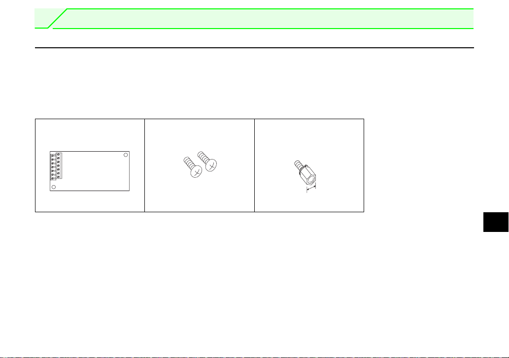
1.1.1 Packing confirmation
Check the enclosed items.
Plug-in option
.........................................1
Mounting screw (M3 × 6mm)
.............. 2 (Refer to p age 6.)
700 series.
Hex-head screw fo r o pt ion
mounting (5.5mm)
...............1 (R ef er to page 6.)
5.5mm
1
1
Page 7
PRE-OPERATION INST RUC TI ON S
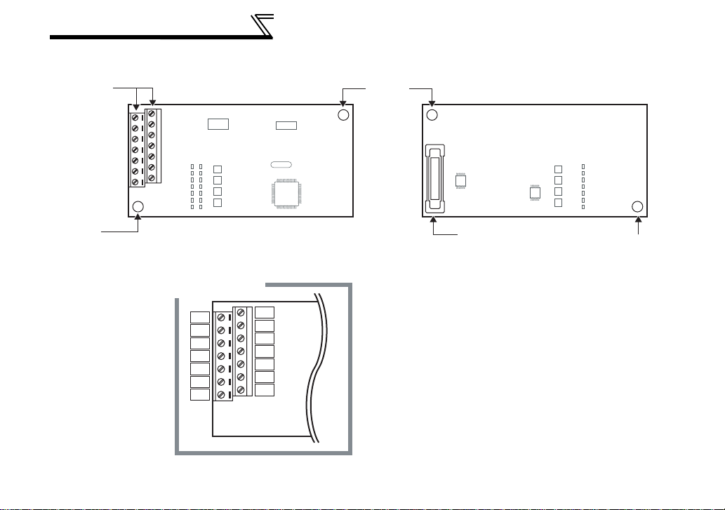
1.1.2 Parts
Terminal
block
Front view
Mounting
hole
Rear view
Mounting
hole
2
Terminal layout
AMC
NC
SE
Y3
Y4
Y5
Y6
AM0
AM1
NC
SE
Y0
Y1
Y2
Connector
Connect to the inverter
option slot
(Refer to page 6.)
Mounting hole
Page 8

1.1.3 Specifications
(1) Output signals
Voltage output (across terminals AM0-AMC) 0 to 10VMAXDC
Current output (across terminals AM1-AMC) 0 to 20mADC
(2) Output resolution
Voltage output 3mV
Current output 10
(3) Output accuracy (reference value)
±10% of the full-scale output value
Depends on the output signal type.
(4) Meters used
• Voltmeter
DC voltmeter Full-scale 10V (internal impedance 10kΩ or more)
• Ammeter
DC ammeter Full-scale 20mA (internal impedance 300Ω or less)
• Wiring length
Maximum 10m
µA
PRE-OPERATION INST RU CT ION S
1
3
Page 9

MEMO
4
Page 10
2 INSTALLATION AND WIRING
2.1 Pre-Installation Inst ructions
Make sure that the input power of the inverter is off.
CAUTION
With input power on, do not install or remove the plug-in opt ion. Otherwise, the inverter and
plug-in option may be damaged.
2
5
Page 11

INSTALLATION AND WIRING
2.2 Installation P rocedure
1) Remove the inverter front cover.
2) Mount the hex-head screw for option
1)
Screw hole for
option mounting
Inverter side
option
connector
3)
Screw hole for
option mounting
(on earth plate)
Hex-head screw
for option mounting
CAUTION
1. When the inverte r can not recognize that the option unit is mounted due to improper installation, etc.,
" " (option alarm) is displayed.
2. Note that a hex-head screw for opti on mounting or mountin g screw may drop duri ng mounting and remova l.
2)
4)
Mounting
screws
mounting into the inverter screw hole (on
earth plate). (size 5.5mm, tightening
torque 0.56N⋅m to 0.75N⋅m)
3) Securely fit the connector of the plug-in
option to the inverter connector along the
guides.
4) Securely fix the both right and left sides
of the plug-in option to the inverter with
the accessory mounting screws. If the
screw holes do not line-up, the connector
may not have been plugged snugly.
Check for loose plugging.
REMARKS
After removing two screws on the right and left
places, remove the plu g- in opt ion.
(The plug-in option is easi l y re m oved if the
control circuit terminal bl ock is re moved before .)
6
Page 12

INSTALLATION AND WIRING
2.3 Wiring
(1) Strip off the sheath of the cable to wire.
Strip off the sheath about the size below. If the length of the sheath pealed is too long, a short circuit
may occur among neighboring wires. If the length is too short, wires might come off.
Cable stripping size
5mm
REMARKS
Information on bar terminals
Introduced products (as of October, 2003): Phoenix Contact Co.,Ltd.
Terminal Screw
Size
M2 Al 0.5-6WH A 0.5-6 0.3 to 0.5
⋅ Bar term i nal cr i m pi ng t ool: CRIMPFOX ZA3 (Phoe ni x C o ntact C o. , Ltd.)
When using th e bar t ermi na l ( wit ho ut insu la ti on sl ee ve) ,
use care so that the twisted wires do not come out.
(2) Loosen the terminal screw and insert the cable into the terminal.
Screw Size Tightening Torque Cable Size Screwdriver
M2 0.22N⋅m to 0.25N⋅m
CAUTION
Undertightening can cause cable disconnection or malfunction. Overtightening can cause a short circuit or
malfunction due to damage to the screw or unit.
Wire the stripped cable after twisting it to prevent it from becoming loose.
In addition, do not solder it.
Use a bar type terminal as required.
Bar Terminal Model
(with insulation sleeve)
Bar Terminal Model
(without insulation sleeve)
0.3mm
2
to 0.75mm
2
(Tip thickness: 0.4mm/tip width: 2.5mm )
Wire Size (mm2)
Small flat-blade screwdriver
2
7
Page 13

INSTALLATION AND WIRING
C
(3) For wiring of the 30K(00620 (EC Version)) or less, route wires between the control circuit terminal block
and front cover. If cables can not be routed between the control circuit terminal block and front cover due
to the increased number of cables, remove a hook of the front cover and use a space become available.
For wiring of the 37K(00770 (EC Version)) or more, use the space on the left side of the control circuit
terminal block.
Wiring can be also performed using a cable
groove in the inverter side surface
Cut off
with a
nipper,
etc.
Cut off a hook on the inverter
front cover side surface.
(Cut off so that no portion is left.)
Control circuit
terminal block
30K or less 37K or more
REMARKS
When wires can no t b e co nn ect ed to th e ter mi nal block due t o p a ral le l c o nn ect i on o r w il l not f it i n t he w ir i ng s p ac e due
to large gauge or the incr eased number of cables, pe rfor m wiring by using a junction te rm inal block, etc.
AUTION
Do not use empty t erminals as junction terminals because t hey are used in the o ption unit. If
they are used as the junction terminals, the option unit may be damaged.
When installing the inverter front cover, the cables to the inverter's control circuit terminals and
option unit term ina ls s ho uld b e ro uted p rop erly in th e wiring space to pr even t them f rom b eing
caught between the inverter and its cover.
After wiring, wire offcuts must not be left in the inverter. They may cause a fault, failure or
malfunction.
8
Page 14

3 PARAMETER LIST
When the FR-A7AY is mounted on the inverter, the following parameters are extended.
Parameter
Number
306 Analog output signal selection
307 Setting for zero analog output 0 to100% 0.1 0%
308 Setting for m aximum analog output 0 to100% 0.1 100%
309
310
311
312
EXTENSION ANALOG OUTPUT
323 AM0 0V ad ju st m en t 900 to1100% 1 1000%
324 AM1 0mA adjustment 900 to 1100% 1 1000%
C0(900) FM(CA) terminal calibration
C1(901) AM terminal calibration
Analog output signal voltag e/ current
switchover
Analog meter voltage output
selection
Setting for zero analog meter
voltage output
Setting for maximum analog meter
voltage output
Name Setting Range
1 to 3, 5, 6, 8,(9),
10 to14,17, 21, 24, 50,
52, 53
0, 1, 10, 11 1 0
1 to 3, 5, 6, 8, (9),
10 to14, 17, 21, 24, 50,
52, 53
0 to100% 0.1 0%
0 to100% 0.1 100%
Minimum
Increments
12
12
Initial
Value
Refer to
Page
11 and
later
3
9
Page 15

PARAMETER LIST
Parameter
Number
313 DO0 output selection
314 DO1 output selection
315 DO2 output selection
316 DO3 output selection
317 DO4 output selection
318 DO5 output selection
DIGITAL OUTPUT
319 DO6 output selection
Name Setting Range
0 to 5, (7), 8, 10 to 19,
25, 26, 45 to 47, 64, 70,
(71 to 78), 86 to 96, 98,
99, 100 to 105, (107),
108, 110 to 116, 125,
126, 145 to 147, 164,
170, 186 to 196, 198,
199, 9999
Minimum
Increments
1 9999
Initial
Value
Refer to
Page
21 and
later
10
Page 16

4 EXTENSION ANALOG OUTPUT
4.1 Wiring Example
By setting the Pr. 306 to Pr. 312 values, analog signals such as the output frequency and output current can
be output from the voltage output terminal (AM0) and current output terminal (AM1).
Connect the voltmeter or ammeter as shown below:
Power
supply
(Voltmeter)
(Ammeter)
MCCB
0 to 10VDC
+
-
+
0 to 20 mADC
-
Inverter
FR-A7AY
AM0
AM1
AMC
Motor
IM
CAUTION
The wiring length between the FR-A7AY and the voltmeter/ammeter should be 10m maximum.
4
11
Page 17

EXTENSION ANALOG OUTPUT
4.2 Internal Block Diagram
The following is the internal block diagram about the FR-A7AY analog output function.
AM0
Voltage amplifier
Connector
Controller
Current amplifier
Common to
AM0/AM1
AM1
AMC
12
Page 18

4.3 Terminals
AMC
NC
SE
Y3
Y4
Y5
Y6
AM0
AM1
NC
SE
Y0
Y1
Y2
EXTENSION ANALOG OUTPUT
Terminal Symbol Terminal Name Description
AM0
AM1
AMC
Y0 to Y6
SE
NC (empty) Do not use.
Voltage output
terminal
Current ou t put
terminal
Common
terminal
Connect a DC voltmeter (10VDC).
Connect a DC ammeter (2 0m ADC).
Common to AM0 and AM1
Used for analog output function. (Refer to page 21 )
13
4
Page 19

EXTENSION ANALOG OUTPUT
4.4 Extension Analog Output Function Parameter List
Parameter
Number
306 Analog output signal selection
307 Setting for zer o analog output 0 to 100% 0.1 0%
308 Setting for m axi m um analog output 0 to 100% 0.1 100%
309
310 Analog meter voltage output
311
312
323 AM0 0V adjustment 900 to 1100% 1 1000%
324 AM1 0mA adj u st m ent 900 to 1100% 1 1000%
C0(900) FM terminal calibration
C1(901) AM terminal calibration
Analog output signal voltag e/ cur r ent
switchover
Setting for zero analog mete r
voltage output
Setting for maximum analog meter
voltage output
Name Setting Range
1 to 3, 5, 6, 8,
(9), 10 to 14, 17,
21, 24, 50, 52, 53
0, 1, 10, 11 1 0
1 to 3 , 5, 6, 8,
(9), 10 to 14, 17,
21, 24, 50, 52, 53
0 to 100% 0.1 0%
0 to 100% 0.1 100%
Minimum
Increments
12
12
Initial
Value
REMARKS
For Pr. 306 and Pr. 310, write is enabled even when "0" is set in Pr. 77.
14
Page 20

EXTENSION ANALOG OUTPUT
4.5 Adjustment Proc edure
4.5.1 Setting of analog output signal voltage/current switchover (Pr. 309)
Use Pr. 309 Analog output sign al voltage/current switcho ver to select whether to output the same signal or
different signals from terminal AM0 (voltage output) and terminal AM1(current output).
Pr. 309
Setting
0
(initial
value)
10
1
11
Description
Same select signals are output
from the voltage output terminal
(AM0) and current output
terminal (AM1). The signal set in
Pr. 306 Analog output signal
selection is made valid. (The
setting of Pr. 310 is made i nvalid.)
Different select signals are
output from voltage output
terminal (AM0) and current
output terminal (AM1).
Terminal
AM0
Pr. 306 : Select the output signal.
Pr. 307 : Output signal value for zero analog output
AM1
Pr. 308 : Output signal value for maximum analog output
Pr. 306 : Select the output signal.
AM0
Pr. 307 : Analog output value for zero output signal
AM1
Pr. 308 : Analog output value for maximum output signal
Pr. 310 : Select the output signal.
Pr. 311 : Output signal value for zero analog output
AM0
Pr. 312 : Output signal value for maximum analog output
Pr. 306 : Select the output signal.
AM1
Pr. 307 : Output signal value for zero analog output
Pr. 308 : Output signal value for maximum analog output
Pr. 310 : Select the output signal.
Pr. 311 : Analog output value for zero output signal
AM0
Pr. 312 : Analog output value for maximum output signal
Pr. 306 : Select the output signal.
Pr. 307 : Analog output value for zero output signal
AM1
Pr. 308 : Analog output value for maximum output signal
Parameters for Setting
Parameters
for
Adjustment
Pr. 323
Pr. 324
C1 (Pr. 901)
Pr. 323
C0 (Pr. 900)
Pr. 324
C1 (Pr. 901)
Pr. 323
C0 (Pr. 900)
Pr. 324
C1 (Pr. 901)
REMARKS
Analog output means voltage (0 to 10 V) and current (0 to 20m A) out put from terminal AM0 and AM1, and output
signal means t he monitor signal (refer to page 18) set in Pr. 306 and Pr. 310.
4
15
Page 21

EXTENSION ANALOG OUTPUT
4.5.2 Calibration of meter
(1) Outputting the same select signals from terminals AM0 and AM1 (Pr. 309 = 0 or 10)
START
Connect a DC voltmeter (or DC ammeter) across
terminals AM0 (or terminal AM1) and AMC.
Use Pr. 323 (Pr. 324) to calibrate the meter
when the voltage (current) input is 0.
Set "21" (reference voltage output) in Pr. 306.
Run the inverter
Use Pr. 901 to perform adjustment, then set.
END
In Pr. 306, set the types of the signals to be output.
(Refer to page 18.)
At this time, check that the polarity is correct
If the meter needle does not point to 0 when voltage or current input is 0,
use Pr. 323 AM0 0V adjustment or Pr. 324 AM1 0mA adjustment to
calibrate the meter
At this time, the following analog signal is actually output and deflects the meter.
<across terminals AM0-AMC>
Maximum output voltage set previously (factory setting: 10VDC)
<across terminals AM1-AMC>
Maximum output current set previously (factory setting: 20mADC)
press to set.
CAUTION
1. If calibration is made without "21" (reference voltage output) set in Pr. 306, Terminals FM/AM of the inve rt e r
is calibrated. To calibrate the extension analog output, always set "21" in Pr. 306.
2. When the plug-in opt ion used was remoun ted on other i nverter, use Pr. 323 and Pr. 324 to calibrate again.
16
Page 22

EXTENSION ANALOG OUTPUT
(2) Outputting different select signals from terminals AM0 and AM1 (Pr. 309 = 1 or 11)
START
Connect a DC voltmeter (or DC ammeter)
across terminals AM0 (or terminal AM1)
and AMC.
Use Pr. 323 (or Pr. 324) to calibrate the
meter when the voltage (current) input is 0.
Set "21" (reference voltage output) in Pr.
306 and Pr. 310.
Run the inverter
Terminal AM0 Terminal AM1
Use Pr. 900 to set
In Pr. 306 and Pr. 310, set the types of the signals to be output.
(Refer to page 18.)
Use Pr. 901 to set
END
At this time, check that the polarity is correct
If the meter needle does not point to 0 when voltage or current input is 0,
use Pr. 323 AM0 0V adjustment or Pr. 324 AM1 0mA adjustment to
calibrate the meter
At this time, the following analog signal is actually output and deflects the meter.
<across terminals AM0-AMC>
Maximum output voltage set previously (factory setting: 10VDC)
<across terminals AM1-AMC>
Maximum output current set previously (factory setting: 20mADC)
The inverter may be run in either the PU or external operation mode.
press to set.
CAUTION
1. If calibrat i on i s m ade wit hout "21" (reference voltage output ) se t in Pr. 306 or Pr. 310, terminals FM/AM of
the invert er is calibrated. To calibrate the exten sion analog ou t p ut, always set "21" in Pr. 306.
2. When the plug-in option used was remounted on other inverter, use Pr. 323 and Pr. 324 to calibrate again.
4
17
Page 23

EXTENSION ANALOG OUTPUT
4.5.3 Output signal setting
Set the output signals to be monitored. Set Pr. 306 to output the same signal from terminals AM0 and AM1
and Pr. 306 and Pr. 310 to output different signals. For details of signal definitions, refer to Pr. 54 and Pr. 158
of the inverter manual (applied).
Pr. 306/Pr. 310
Setting
1 Output frequency 0.01Hz Pr. 55
2 Output current 0.01A/0.1A *2 Pr. 56
3 Output voltage 0.1V 800V
5 Frequency setting 0.01Hz Pr. 55
6 Running speed 1(r/min) The val u e c on v ert e d w i th th e Pr. 37 value from Pr . 55 .
8 Converter output voltage 0.1V 800V
9 *1 Regenerative brake duty 0.1% Pr. 70
10
11 Output current peak value 0.01A/0.1A *2 Pr. 56
12
13 Input power 0.01kW/0.1kW *2 Rated inverter power × 2
14 Output power 0.01kW/0.1kW *2 Rated inverter power × 2
17 Load meter 0.1% Pr. 56
21 Reference voltage output
24 Motor load factor 0.1% 200%
50 Power saving effect
52 PID set point 0.1% 100%
53 PID process value 0.1% 100%
*1 Setting can be made only for the 7 5K( 01800-EC, S75K-CH) or more.
*2 The setting depends on capac ities . ( 55K (01160-EC, 55K-CH) or less/75K (01800-EC, S75K-C H ) o r mor e. )
Types of Monitor Increments Full-Scale Value
Electronic thermal relay
function load factor
Converter output voltage
peak value
Var iable according to parameters
0.1% Electronic thermal relay function operation level
0.1V 800V
Inverter capacity
18
Page 24

EXTENSION ANALOG OUTPUT
4.5.4 Analog signal adjustment [Pr. 307, Pr. 308, Pr. 311, Pr. 312]
Use Pr. 307 or Pr. 311 to set for zero analog output (meter points 0).
In addition, use Pr. 308 or Pr. 312 to set for maximum analog output (full-scale).
Use Pr. 307 to set the value for zero analog output and Pr. 308 for maximum analog output when outputting
the same signal from terminals AM0 and AM1.
Use Pr. 307(AM1) and Pr. 311(AM0) to set the value for zero analog output and Pr. 308(AM1) and Pr.
312(AM0) for maximum analog output when outputting different signals from terminals AM0 and AM1. (Refer
to page 15.)
When Pr. 309 = 0, 1 When Pr. 309 = 10, 11
Analog output
Voltage
Current
20mA
(AM1)
0
(AM0)
10V
Output signal value (Pr. 308 or
Pr. 312) for maximum analog output
Output signal
value
Output signal value (Pr. 307 or
Pr. 311) for zero analog output
REMARKS
When Pr. 307 ≥ Pr. 308, Pr. 311 ≥ Pr. 312, the output
values at terminals AM0 and AM1 are alway s zero.
Analog output
Voltage
Current
20mA
(AM1)
0
(AM0)
10V
Output signal value (Pr. 307 or
Pr. 311) for zero output signal
Analog output
value (Pr. 308 or
Pr. 312) for
maximum
output signal
Output signal
value
REMARKS
When Pr. 307 = Pr. 308, Pr. 311 = Pr. 312, the output
values at terminals AM0 and AM 1 are values set in
parameters always.
4
19
Page 25

EXTENSION ANALOG OUTPUT
C
4.6 Instructions
(1) A voltmeter having smaller internal impedance (or an ammeter having larger internal impedance) than
the value indicated in the Specifications may not deflect to full-scale and may not be calibrated.
(2) When calibrating a meter which has a small full-scale value, set the output of terminal AM0 (or AM1) to
the minimum without the meter connected. Then, connect the meter and make calibration.
AUTION
This option unit is factory-set to provide the full-scale output of 10VDC and 20mADC. Hence, a
voltmeter (7VDC or less) or an ammeter (14mADC or less) with a small full-scale value may be
damaged accidentally during calibration. This should be fully noted.
(3) Set
(4) When an option error occurs, all outputs are tuned off.
"0%" in Pr. 307 (Pr . 31 1) and "100%" in Pr. 308 ( Pr. 312) when calibrating Pr . 323, Pr. 324, C0 (Pr. 900),
C1 (Pr. 901) when Pr. 309 =
"10 or 11 " to prevent calibration value deviation.
20
Page 26

5 DIGITAL OUTPUT
5.1 Internal Block Diagram
The following is the internal block diagram about the FR-A7AY digital output function
Y0
Connector
Controller
Common to Y0-T6
Y6
SE
5
21
Page 27

DIGITAL OUTPUT
5.2 Terminals
By setting the Pr. 313 to Pr. 319 values, output signals available with an inverter as standard can be output
from the open collector terminals.
(1) Open collector output specifications: Permissible load 24V, 0.1ADC
(2) The circuit logic is the same as that of the inverter.
For details of changing the control logic, refer to the inverter manual (basic).
Terminal Symbol Terminal Name Description
AMC
NC
SE
Y3
Y4
Y5
Y6
AM0
AM1
NC
SE
Y0
Y1
Y2
Y0
Y1 Use Pr. 314 to assign functions.
Y2 Use Pr. 315 to assign functions.
Y3 Use Pr. 316 to assign functions.
Y4 Use Pr. 317 to assign functions.
Digital output
terminals
Y5 Use Pr. 318 to assign functions.
Y6 Use Pr. 319 to assign functions.
SE
Common
terminal
AM0
Used for analog output function. (Refer to page 11) AM1
AMC
NC (empty) Do not use.
Use Pr. 31 3 to assign functions.
This is a common terminal (for sink and
source).
22
Page 28

DIGITAL OUTPUT
5.3 Digital Output Function Parameter List
Parameter Number Name Initial Valu e Setting Range
313 DO0 output selection 9999
314 DO1 output selection 9999
315 DO2 output selection 9999
316 DO3 output selection 9999
317 DO4 output selection 9999
318 DO5 output selection 9999
319 DO6 output selection 9999
REMARKS
⋅ For Pr. 313 to Pr. 319, write is disabled dur i ng operatio n even when "2" is set in Pr. 77 Parameter write disable
selection. When changing the parameter setting, stop the operation.
⋅ With th is fu nct i on , ou tp ut si gnals can be set redundantly.
0 to 5, (7), 8, 10 to 19, 25, 26,
45 to 47, 64, 70, (71 to 78), 86
to 96, 98, 99,
100 to 105, (107), 108, 110 to
116, 125, 126, 145 to 147, 164,
170, 186 to 196, 198, 199,
9999
23
5
Page 29

DIGITAL OUTPUT
5.4 Output Signal List
For details of signal definitions, refer to Pr. 190 to Pr. 196 Output terminal functio n selection of the inverte r
manual (applied).
Setting
Positive
Logic
Negative
Logic
0 100 RUN Inverter running 15 115 FUP PID upper limit
1 101 SU Up to frequency 16 116 RL
2 102 IPF
3 103 OL Overload alarm 18 MC2
4 104 FU Output frequency detection 19 MC3
5 105 FU2
7 107 RBP Regenerative brake prealarm *1 26 126 F IN Heatsink overheat pre-alarm
8 108 THP
10 110 PU PU operation mode 46 146 Y46
11 111 RY Inverter operation ready 47 147 PID During PID control activated
12 112 Y12 Output current detection 64 164 Y64 During retry
13 113 Y13 Zero current detection 70 170
14 114 FDN PID lower limit 71 RO1
Signal
Name
Instantaneous power failure/
undervoltage
Second output frequency
detection
Electronic thermal relay function
prealarm
Function
Setting
Positive
Logic
Negative
Logic
17 MC1
25 125 FAN Fan fault output
45 145 RUN3
Signal
Name
PID forward/reverse rotation output
Commercial power-supply
switchover MC1
Commercial power-supply
switchover MC2
Commercial power-supply
switchover MC3
During inverter running and
start command is on
During deceleration due to
instantaneous power failure
(retained until release)
SLEEP
During PID output suspension
Commercial-power supply side
motor 1 connection RO1
Function
24
*2
Page 30

DIGITAL OUTPUT
Setting
Positive
Logic
Negative
Logic
72 RO2
73 RO3
74 RO4
75 RIO1
76 RIO2
77 RIO3
78 RIO4
Signal
Name
Function
Commercial-power supply side
motor 2 connection RO2
Commercial-power supply side
motor 3 connection RO3
Commercial-power supply side
motor 4 connection RO4
Inverter side motor 1
connection RIO1
Inverter side motor 2
connection RIO2
Inverter side motor 3
connection RIO3
Inverter side motor 4
connection RIO4
*2
*2
*2
*2
*2
*2
*2
Setting
Positive
Logic
Negative
Logic
Signal
Name
90 190 Y90 Life alarm
91 191 Y91 Input MC shut off signal
92 192 Y92
Energy saving average value
updated timing
93 193 Y93 Current average monitor signal
94 194 ALM2 Alarm output 2
95 195 Y95 Maintenance timer signal
96 196 REM Remote output
86 186 Y86 Control circuit capacitor life *3 98 198 LF Minor fault output
87 187 Y87 Main circuit capacitor life *3 99 199 ALM Alarm output
88 188 Y88 Cooling fan life *3 9999 No function
89 189 Y89 Inrush current limit circuit life *3
*1 Setting can be made only for the 75K (01800-EC, S75K-CH) or m or e.
*2 Setting can be made only for EC and CH version.
*3 Y86 to Y89 can not be set from the i nv erter.
REMARKS
When an option error occ ur s, all outputs are tuned off.
Function
25
5
Page 31

REVISIONS
*The manual numbe r i s given on the bottom left of the back cover.
Print Date *Manual Number Revision
May, 2004 IB(NA)-0600165ENG - A First edition
 Loading...