


Fireball lct08
fireball_lct08_jumper.pdf
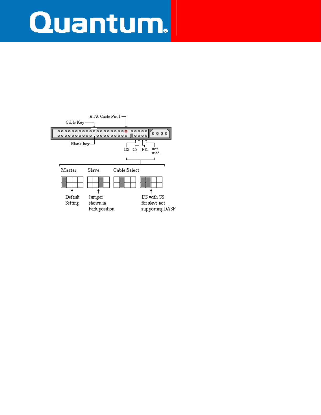
Jumper Settings
DS CS PK Rsvd
Stand Alone (Default) ON OFF X OFF
Master with Slave Present ON OFF X OFF
Slave to Master OFF OFF x OFF
Cable Select * OFF ON X OFF
X= PK is a Parking position. The presence or absence of this jumper has no effect on the drive. Labeling may
indicate to place this jumper when configuring as a slave. This is to provide for retention of the jumper in the event
that it is needed later.
*Note: Cable Select (CS) utilizes a special cable configuration where the drive setting (Master or Slave) is
determined by its position on the 40-pin ATA cable. In this type of configuration both drives will have their jumper
set to CS. Cable Select is utilized on some OEM systems and is typically required for systems utilizing Ultra ATA/66.
For Ultra ATA/66 compliant cables, the master drive is placed on the outside (end) cable connector and the slave
drive is placed on the intermediate cable connector.
1 of 1
Fireball lct08
fireball_lct08_jumper.pdf
Jumper Locations
The Maxtor® Fireball™ lct08 disk drive has only one location where user configurable jumpers are found. The
jumper block is incorporated into the ATA / IDE cable connector. Using the jumper pins you can establish the drive
Master/Slave configuration.
The Maxtor Fireball lct08 was developed by Quantum Corporation prior to its merger with Maxtor.
BIOS Settings
The following BIOS parameters are provided for customers needing to manually configure the Fireball lct08 disk
drive. Both base 2 and base 10 capacity values are displayed.
Logical Cylinders
Logical Heads
Logical Sectors/Track
Total Logical Sectors
Base 10 Capacity
Base 2 Capacity
*Note: ATA (IDE) drives with a physical capacity greater than 8.4GB have their default logical C/H/S values limited
to 16,383/16/63 as per the ATA-4 specification. Drives greater than 8.4GB in capacity require LBA support.
Capacity could be restricted to 8.4GB (or less) due to system BIOS limitations. Check with your system or
motherboard manufacturer to determine if your BIOS supports LBA mode for ATA hard drives greater than 8.4GB.
4.3 GB 8.4 GB 13.0 GB 17.3 GB 26.0 GB
8,912 16,383 * 16,383 * 16,383 * 16,383 *
15 16 16 16 16
63 63 63 63 63
8,421,840 16,514,064 25,429,824 33,906,432 50,859,648
4,311 MB 8,455 MB 13,020 MB 17,360 MB 26,040 MB
4,112 MB 8,063 MB 12,416 MB 16,555 MB 24,833 MB
2 of 2

Fireball lct08
fireball_lct08_jumper.pdf
Special Considerations
BIOS/Operating System Limitations
Hard drives greater than 2.1GB may need to be divided into multiple partitions / logical drives. MS-DOS versions
4.0 through 6.22 allow a maximum primary partition / logical drive size of 2.1GB and are limited to 8.4GB in
physical drive capacity. The file systems supported by Windows 95, Windows 98 and Windows NT are not restricted
to the 8.4GB physical drive limit, but LBA support in the system BIOS is required.
Hard drives greater than 8.4GB in capacity may be restricted to 8.4GB (or less) due to system BIOS limitations,
operating system limitations, or both. Check with your system manufacturer to determine if your BIOS supports
the correct LBA extensions for hard drives greater than 8.4GB.
Ultra ATA/66 Operation
In order to achieve the Ultra ATA/66 transfer speed, you must have a system and a BIOS that will support Ultra
ATA/66. The correct drivers must be loaded, and an Ultra ATA specific data cable must be used. The Ultra ATA
cables use the Cable Select (CS) method rather than the Drive Select (DS) master/slave scheme, so the drive must
be jumpered to enable Cable Select. Please review our application note entitled
further details.
Ultra ATA System Requirements
for
Drive Mounting/Handling Precautions
It is highly recommended that the hard drive be mounted on to the chassis of the system being used for general
operation as well as for test purposes. Failure to hard mount the drive can result in erroneous errors during testing
or normal operation. Please review our
Warning: Never allow objects to come into direct contact with the hard drive’s printed circuit board (PCB) during
operation. This could result in an electrical short and cause irreparable damage to the hard drive as well as loss of
all data. Please observe proper mounting guidelines and specifications as described above when power is applied to
the hard drive.
For Further Review:
ATA Configuration Card
for specifications on drive mounting.
• ATA Configuration Card (Includes Drive Mounting)
• ATA Installation Flowchart
• ATA Installation Guide for Windows NT
• ATA Installation Guide for Windows95/98
• BIOS Support for logical cylinder values > 4095
• DOS/Windows 95 logical drive limitations
• Knowledge Base
• Product Manuals
• Ultra ATA/66 Bus Interface
• Ultra ATA/66 Compatibility with Award BIOS
• Windows NT 4.0 Capacity Issue
3 of 3
 Loading...