

Page 1

Fibre Channel Interface
Page 2

Page 3

Fibre Channel Interface
Page 4

©1997–2004, Seagate Technology LLC All rights reserved
Publication number: 77767496, Rev. D
February 2004
Seagate and Seagate Technology are registered trademarks of Seagate Technology LLC.
SeaTools, SeaFONE, SeaBOARD, SeaTDD, and the Wave logo are either registered trademarks or trademarks of Seagate Technology LLC. Other product names are registered trademarks or trademarks of their owners.
Seagate reserves the right to change, without notice, product offerings or specifications. No
part of this publication may be reproduced in any form without written permission of Seagate
Technology LLC.
Page 5

Revision status summary sheet
Revision Date Sheets Affected
A 03/21/1997 L. Newman/J. Coomes and W. Whittington All
B 08/01/2000 L. Newman/J. Coomes All
C 01/03/2003 L. Newman No change except for new Seagate logo.
D 02/05/2004 K. Schweiss/J. Coomes and W. Paulsen All
Sheets Affected
Document migration/conversion only.
Page 6

Page 7

Contents
1.0 Publication overview . . . . . . . . . . . . . . . . . . . . . . . . . . . . . . . . . . . . . . . . . . . . . . . . . . . . . . . . . . . . . 1
1.1 Acknowledgements . . . . . . . . . . . . . . . . . . . . . . . . . . . . . . . . . . . . . . . . . . . . . . . . . . . . . . . . . 1
1.2 How to use this manual . . . . . . . . . . . . . . . . . . . . . . . . . . . . . . . . . . . . . . . . . . . . . . . . . . . . . . 1
1.3 General interface description. . . . . . . . . . . . . . . . . . . . . . . . . . . . . . . . . . . . . . . . . . . . . . . . . . 2
2.0 Introduction to Fibre Channel . . . . . . . . . . . . . . . . . . . . . . . . . . . . . . . . . . . . . . . . . . . . . . . . . . . . . . 3
2.1 General information . . . . . . . . . . . . . . . . . . . . . . . . . . . . . . . . . . . . . . . . . . . . . . . . . . . . . . . . . 3
2.2 Channels vs. networks . . . . . . . . . . . . . . . . . . . . . . . . . . . . . . . . . . . . . . . . . . . . . . . . . . . . . . 3
2.3 The advantages of Fibre Channel . . . . . . . . . . . . . . . . . . . . . . . . . . . . . . . . . . . . . . . . . . . . . . 4
3.0 Fibre Channel standards . . . . . . . . . . . . . . . . . . . . . . . . . . . . . . . . . . . . . . . . . . . . . . . . . . . . . . . . . . 5
3.1 General information . . . . . . . . . . . . . . . . . . . . . . . . . . . . . . . . . . . . . . . . . . . . . . . . . . . . . . . . . 6
3.1.1 Description of Fibre Channel levels . . . . . . . . . . . . . . . . . . . . . . . . . . . . . . . . . . . . . 6
3.1.1.1 FC-0 . . . . . . . . . . . . . . . . . . . . . . . . . . . . . . . . . . . . . . . . . . . . . . . . . . . . 6
3.1.1.2 FC-1 . . . . . . . . . . . . . . . . . . . . . . . . . . . . . . . . . . . . . . . . . . . . . . . . . . . . 6
3.1.1.3 FC-1.5 . . . . . . . . . . . . . . . . . . . . . . . . . . . . . . . . . . . . . . . . . . . . . . . . . . 6
3.1.1.4 FC-2 . . . . . . . . . . . . . . . . . . . . . . . . . . . . . . . . . . . . . . . . . . . . . . . . . . . . 6
3.1.1.5 FC-3 . . . . . . . . . . . . . . . . . . . . . . . . . . . . . . . . . . . . . . . . . . . . . . . . . . . . 6
3.1.1.6 FC-4 . . . . . . . . . . . . . . . . . . . . . . . . . . . . . . . . . . . . . . . . . . . . . . . . . . . . 7
3.1.2 Relationship between the levels. . . . . . . . . . . . . . . . . . . . . . . . . . . . . . . . . . . . . . . . 7
3.1.3 Topology standards . . . . . . . . . . . . . . . . . . . . . . . . . . . . . . . . . . . . . . . . . . . . . . . . . 7
3.1.4 FC Implementation Guide (FC-IG) . . . . . . . . . . . . . . . . . . . . . . . . . . . . . . . . . . . . . . 7
4.0 Introduction to topologies . . . . . . . . . . . . . . . . . . . . . . . . . . . . . . . . . . . . . . . . . . . . . . . . . . . . . . . . . 9
4.1 Nodes . . . . . . . . . . . . . . . . . . . . . . . . . . . . . . . . . . . . . . . . . . . . . . . . . . . . . . . . . . . . . . . . . . . 9
4.2 Ports . . . . . . . . . . . . . . . . . . . . . . . . . . . . . . . . . . . . . . . . . . . . . . . . . . . . . . . . . . . . . . . . . . . . 9
4.3 Links . . . . . . . . . . . . . . . . . . . . . . . . . . . . . . . . . . . . . . . . . . . . . . . . . . . . . . . . . . . . . . . . . . . 10
4.4 Arbitrated loop topology. . . . . . . . . . . . . . . . . . . . . . . . . . . . . . . . . . . . . . . . . . . . . . . . . . . . . 10
4.5 Topology and port login . . . . . . . . . . . . . . . . . . . . . . . . . . . . . . . . . . . . . . . . . . . . . . . . . . . . . 11
4.6 Port bypass circuits . . . . . . . . . . . . . . . . . . . . . . . . . . . . . . . . . . . . . . . . . . . . . . . . . . . . . . . . 11
5.0 Data encoding (FC-1) . . . . . . . . . . . . . . . . . . . . . . . . . . . . . . . . . . . . . . . . . . . . . . . . . . . . . . . . . . . . 13
5.1 Encoding and decoding . . . . . . . . . . . . . . . . . . . . . . . . . . . . . . . . . . . . . . . . . . . . . . . . . . . . . 13
5.2 Buffer-to-buffer data transfers . . . . . . . . . . . . . . . . . . . . . . . . . . . . . . . . . . . . . . . . . . . . . . . . 14
5.3 Data hierarchy . . . . . . . . . . . . . . . . . . . . . . . . . . . . . . . . . . . . . . . . . . . . . . . . . . . . . . . . . . . . 15
5.3.1 Transmission words . . . . . . . . . . . . . . . . . . . . . . . . . . . . . . . . . . . . . . . . . . . . . . . . 15
5.3.1.1 Data characters . . . . . . . . . . . . . . . . . . . . . . . . . . . . . . . . . . . . . . . . . . 15
5.3.1.2 Special characters . . . . . . . . . . . . . . . . . . . . . . . . . . . . . . . . . . . . . . . . 15
5.4 Ordered sets . . . . . . . . . . . . . . . . . . . . . . . . . . . . . . . . . . . . . . . . . . . . . . . . . . . . . . . . . . . . . 15
5.4.1 Primitive signals . . . . . . . . . . . . . . . . . . . . . . . . . . . . . . . . . . . . . . . . . . . . . . . . . . . 15
5.4.1.1 Primitive signals used as frame delimiters. . . . . . . . . . . . . . . . . . . . . . 16
5.4.1.2 Primitive signals custom made for arbitrated loop topologies . . . . . . . 18
5.4.2 Primitive sequences . . . . . . . . . . . . . . . . . . . . . . . . . . . . . . . . . . . . . . . . . . . . . . . . 19
5.4.2.1 Primitive sequences custom made for Arbitrated Loop topologies . . . 20
6.0 Framing protocol (FC-2). . . . . . . . . . . . . . . . . . . . . . . . . . . . . . . . . . . . . . . . . . . . . . . . . . . . . . . . . . 23
6.1 Frames . . . . . . . . . . . . . . . . . . . . . . . . . . . . . . . . . . . . . . . . . . . . . . . . . . . . . . . . . . . . . . . . . 23
6.1.1 Frame structure . . . . . . . . . . . . . . . . . . . . . . . . . . . . . . . . . . . . . . . . . . . . . . . . . . . 23
6.1.1.1 Start-of-frame (SOF) delimiter . . . . . . . . . . . . . . . . . . . . . . . . . . . . . . . 24
6.1.1.2 Frame header . . . . . . . . . . . . . . . . . . . . . . . . . . . . . . . . . . . . . . . . . . . 24
6.1.1.3 Data field (payload) . . . . . . . . . . . . . . . . . . . . . . . . . . . . . . . . . . . . . . . 28
6.1.1.4 CRC field . . . . . . . . . . . . . . . . . . . . . . . . . . . . . . . . . . . . . . . . . . . . . . . 28
6.1.1.5 End-of-frame (EOF) delimiter. . . . . . . . . . . . . . . . . . . . . . . . . . . . . . . . 28
6.2 Frame sequences . . . . . . . . . . . . . . . . . . . . . . . . . . . . . . . . . . . . . . . . . . . . . . . . . . . . . . . . . 28
Fibre Channel Interface Manual, Rev. D v
Page 8

6.3 Exchanges . . . . . . . . . . . . . . . . . . . . . . . . . . . . . . . . . . . . . . . . . . . . . . . . . . . . . . . . . . . . . . . 28
6.4 Credit . . . . . . . . . . . . . . . . . . . . . . . . . . . . . . . . . . . . . . . . . . . . . . . . . . . . . . . . . . . . . . . . . . . 29
7.0 Classes of service (FC-2) . . . . . . . . . . . . . . . . . . . . . . . . . . . . . . . . . . . . . . . . . . . . . . . . . . . . . . . . . 31
7.1 Class 1 . . . . . . . . . . . . . . . . . . . . . . . . . . . . . . . . . . . . . . . . . . . . . . . . . . . . . . . . . . . . . . . . . . 31
7.2 Class 2 . . . . . . . . . . . . . . . . . . . . . . . . . . . . . . . . . . . . . . . . . . . . . . . . . . . . . . . . . . . . . . . . . . 31
7.3 Class 3 . . . . . . . . . . . . . . . . . . . . . . . . . . . . . . . . . . . . . . . . . . . . . . . . . . . . . . . . . . . . . . . . . . 31
7.3.1 Class 3 flow control . . . . . . . . . . . . . . . . . . . . . . . . . . . . . . . . . . . . . . . . . . . . . . . . 32
7.4 Classes 4 and 5 . . . . . . . . . . . . . . . . . . . . . . . . . . . . . . . . . . . . . . . . . . . . . . . . . . . . . . . . . . . 32
8.0 FC Arbitrated Loop concepts. . . . . . . . . . . . . . . . . . . . . . . . . . . . . . . . . . . . . . . . . . . . . . . . . . . . . . 33
8.1 Arbitrated Loop physical address (AL_PA) . . . . . . . . . . . . . . . . . . . . . . . . . . . . . . . . . . . . . . 33
8.2 Loop initialization . . . . . . . . . . . . . . . . . . . . . . . . . . . . . . . . . . . . . . . . . . . . . . . . . . . . . . . . . . 35
8.2.1 Loop initialization state machine . . . . . . . . . . . . . . . . . . . . . . . . . . . . . . . . . . . . . . 45
8.2.2 Loop reinitialization . . . . . . . . . . . . . . . . . . . . . . . . . . . . . . . . . . . . . . . . . . . . . . . . . 46
8.3 Accessing another L_Port . . . . . . . . . . . . . . . . . . . . . . . . . . . . . . . . . . . . . . . . . . . . . . . . . . . 46
8.3.1 Access fairness . . . . . . . . . . . . . . . . . . . . . . . . . . . . . . . . . . . . . . . . . . . . . . . . . . . 47
8.3.2 Access unfairness . . . . . . . . . . . . . . . . . . . . . . . . . . . . . . . . . . . . . . . . . . . . . . . . . 48
8.3.3 Clock skew management . . . . . . . . . . . . . . . . . . . . . . . . . . . . . . . . . . . . . . . . . . . . 48
8.4 Loop ports . . . . . . . . . . . . . . . . . . . . . . . . . . . . . . . . . . . . . . . . . . . . . . . . . . . . . . . . . . . . . . . 48
8.4.1 Maximum number of NL_Ports. . . . . . . . . . . . . . . . . . . . . . . . . . . . . . . . . . . . . . . . 48
8.4.2 Blocking switch emulation . . . . . . . . . . . . . . . . . . . . . . . . . . . . . . . . . . . . . . . . . . . 49
8.4.3 Non-meshed environment . . . . . . . . . . . . . . . . . . . . . . . . . . . . . . . . . . . . . . . . . . . 49
8.4.4 Assigned AL_PA values . . . . . . . . . . . . . . . . . . . . . . . . . . . . . . . . . . . . . . . . . . . . . 50
9.0 Fibre Channel link services . . . . . . . . . . . . . . . . . . . . . . . . . . . . . . . . . . . . . . . . . . . . . . . . . . . . . . . 51
9.1 Basic link services . . . . . . . . . . . . . . . . . . . . . . . . . . . . . . . . . . . . . . . . . . . . . . . . . . . . . . . . . 52
9.1.1 Abort Sequence (ABTS) . . . . . . . . . . . . . . . . . . . . . . . . . . . . . . . . . . . . . . . . . . . . . 53
9.1.2 Basic Accept (BA_ACC) . . . . . . . . . . . . . . . . . . . . . . . . . . . . . . . . . . . . . . . . . . . . . 54
9.1.3 Basic Reject (BA_RJT) . . . . . . . . . . . . . . . . . . . . . . . . . . . . . . . . . . . . . . . . . . . . . . 55
9.2 Extended link services . . . . . . . . . . . . . . . . . . . . . . . . . . . . . . . . . . . . . . . . . . . . . . . . . . . . . . 56
9.2.1 Port Login (PLOGI) (02x) . . . . . . . . . . . . . . . . . . . . . . . . . . . . . . . . . . . . . . . . . . . . 58
9.2.2 Port Logout (PLOGO) (03x) . . . . . . . . . . . . . . . . . . . . . . . . . . . . . . . . . . . . . . . . . . 66
9.2.3 Fabric Login (FLOGI) (04) . . . . . . . . . . . . . . . . . . . . . . . . . . . . . . . . . . . . . . . . . . . 67
9.2.4 Process Login (PRLI) . . . . . . . . . . . . . . . . . . . . . . . . . . . . . . . . . . . . . . . . . . . . . . . 72
9.2.5 Process Logout (PRLO) . . . . . . . . . . . . . . . . . . . . . . . . . . . . . . . . . . . . . . . . . . . . . 77
9.2.6 Third Party Process Logout (TPRLO). . . . . . . . . . . . . . . . . . . . . . . . . . . . . . . . . . . 81
9.2.7 Read Link Error Status Block (RLS) . . . . . . . . . . . . . . . . . . . . . . . . . . . . . . . . . . . . 85
9.2.8 Reinstate Recovery Qualifier (RRQ) . . . . . . . . . . . . . . . . . . . . . . . . . . . . . . . . . . . 88
9.2.9 Port Discovery (PDISC) . . . . . . . . . . . . . . . . . . . . . . . . . . . . . . . . . . . . . . . . . . . . . 90
9.2.10 Discover Address (ADISC) . . . . . . . . . . . . . . . . . . . . . . . . . . . . . . . . . . . . . . . . . . . 91
9.2.11 Report Node Capabilities (RNC) . . . . . . . . . . . . . . . . . . . . . . . . . . . . . . . . . . . . . . 94
9.2.12 Link Service Reject (LS_RJT) . . . . . . . . . . . . . . . . . . . . . . . . . . . . . . . . . . . . . . . . 96
9.3 FC common transport . . . . . . . . . . . . . . . . . . . . . . . . . . . . . . . . . . . . . . . . . . . . . . . . . . . . . . 97
9.3.1 Register FC-4 Types Name Service (RFT_ID). . . . . . . . . . . . . . . . . . . . . . . . . . . . 99
10.0 Enclosure services interface (ESI) . . . . . . . . . . . . . . . . . . . . . . . . . . . . . . . . . . . . . . . . . . . . . . . . 101
10.1 Discovery process . . . . . . . . . . . . . . . . . . . . . . . . . . . . . . . . . . . . . . . . . . . . . . . . . . . . . . . . 101
10.2 8045 mode . . . . . . . . . . . . . . . . . . . . . . . . . . . . . . . . . . . . . . . . . . . . . . . . . . . . . . . . . . . . . . 102
10.2.1 8045 ESI pinouts . . . . . . . . . . . . . . . . . . . . . . . . . . . . . . . . . . . . . . . . . . . . . . . . . 103
10.3 8067 mode . . . . . . . . . . . . . . . . . . . . . . . . . . . . . . . . . . . . . . . . . . . . . . . . . . . . . . . . . . . . . . 104
10.3.1 8067 ESI command . . . . . . . . . . . . . . . . . . . . . . . . . . . . . . . . . . . . . . . . . . . . . . . 104
10.3.2 8067 ESI interface pinouts . . . . . . . . . . . . . . . . . . . . . . . . . . . . . . . . . . . . . . . . . . 105
10.3.3 8067 information format . . . . . . . . . . . . . . . . . . . . . . . . . . . . . . . . . . . . . . . . . . . . 105
10.4 ESI command transfer . . . . . . . . . . . . . . . . . . . . . . . . . . . . . . . . . . . . . . . . . . . . . . . . . . . . . 106
10.4.1 ESI read transfer . . . . . . . . . . . . . . . . . . . . . . . . . . . . . . . . . . . . . . . . . . . . . . . . . 106
vi Fibre Channel Interface Manual, Rev. D
Page 9

10.4.2 ESI write transfer . . . . . . . . . . . . . . . . . . . . . . . . . . . . . . . . . . . . . . . . . . . . . . . . . 106
10.5 Enclosure-initiated ESI transfer . . . . . . . . . . . . . . . . . . . . . . . . . . . . . . . . . . . . . . . . . . . . . . 107
10.5.1 EIE Discovery. . . . . . . . . . . . . . . . . . . . . . . . . . . . . . . . . . . . . . . . . . . . . . . . . . . . 107
10.5.2 EIE operations . . . . . . . . . . . . . . . . . . . . . . . . . . . . . . . . . . . . . . . . . . . . . . . . . . . 109
10.5.3 Enclosure requested information . . . . . . . . . . . . . . . . . . . . . . . . . . . . . . . . . . . . . 110
10.5.3.1 Device Standard Inquiry Data page . . . . . . . . . . . . . . . . . . . . . . . . . 113
10.5.3.2 Device Address page. . . . . . . . . . . . . . . . . . . . . . . . . . . . . . . . . . . . . 114
10.5.3.3 Loop Position Map page . . . . . . . . . . . . . . . . . . . . . . . . . . . . . . . . . . 116
10.5.3.4 Device Identification page . . . . . . . . . . . . . . . . . . . . . . . . . . . . . . . . . 117
10.5.3.5 Device Temperature page . . . . . . . . . . . . . . . . . . . . . . . . . . . . . . . . . 118
10.5.3.6 Port Parameters page . . . . . . . . . . . . . . . . . . . . . . . . . . . . . . . . . . . . 119
10.5.3.7 Link Status page . . . . . . . . . . . . . . . . . . . . . . . . . . . . . . . . . . . . . . . . 120
10.5.3.8 Spin-Down Control Action Specific Bits . . . . . . . . . . . . . . . . . . . . . . 123
10.5.3.9 ESI data validation . . . . . . . . . . . . . . . . . . . . . . . . . . . . . . . . . . . . . . . 124
11.0 SCSI operations . . . . . . . . . . . . . . . . . . . . . . . . . . . . . . . . . . . . . . . . . . . . . . . . . . . . . . . . . . . . . . . 125
11.1 SCSI-FCP . . . . . . . . . . . . . . . . . . . . . . . . . . . . . . . . . . . . . . . . . . . . . . . . . . . . . . . . . . . . . . 125
11.1.1 FC-4 mapping layer . . . . . . . . . . . . . . . . . . . . . . . . . . . . . . . . . . . . . . . . . . . . . . . 125
11.2 FCP CMND . . . . . . . . . . . . . . . . . . . . . . . . . . . . . . . . . . . . . . . . . . . . . . . . . . . . . . . . . . . . . 126
11.2.1 Command Descriptor Block (CDB) . . . . . . . . . . . . . . . . . . . . . . . . . . . . . . . . . . . 130
11.2.1.1 Operation Code . . . . . . . . . . . . . . . . . . . . . . . . . . . . . . . . . . . . . . . . . 130
11.2.1.2 Logical block address . . . . . . . . . . . . . . . . . . . . . . . . . . . . . . . . . . . . 132
11.2.1.3 Operation code . . . . . . . . . . . . . . . . . . . . . . . . . . . . . . . . . . . . . . . . . 132
11.2.1.4 Relative address bit . . . . . . . . . . . . . . . . . . . . . . . . . . . . . . . . . . . . . . 132
11.2.1.5 Transfer length. . . . . . . . . . . . . . . . . . . . . . . . . . . . . . . . . . . . . . . . . . 132
11.2.1.6 Control byte . . . . . . . . . . . . . . . . . . . . . . . . . . . . . . . . . . . . . . . . . . . . 133
11.3 FCP XFER RDY . . . . . . . . . . . . . . . . . . . . . . . . . . . . . . . . . . . . . . . . . . . . . . . . . . . . . . . . . 134
11.4 FCP DATA. . . . . . . . . . . . . . . . . . . . . . . . . . . . . . . . . . . . . . . . . . . . . . . . . . . . . . . . . . . . . . 137
11.5 FCP RSP . . . . . . . . . . . . . . . . . . . . . . . . . . . . . . . . . . . . . . . . . . . . . . . . . . . . . . . . . . . . . . . 140
11.5.1 Extended Sense Data format . . . . . . . . . . . . . . . . . . . . . . . . . . . . . . . . . . . . . . . . 145
11.5.1.1 Sense Key Specific Valid (SKSV) and Sense Key Specific . . . . . . . . 147
11.5.1.2 Current and deferred errors . . . . . . . . . . . . . . . . . . . . . . . . . . . . . . . . 153
11.6 Parameter rounding . . . . . . . . . . . . . . . . . . . . . . . . . . . . . . . . . . . . . . . . . . . . . . . . . . . . . . . 154
12.0 Commands . . . . . . . . . . . . . . . . . . . . . . . . . . . . . . . . . . . . . . . . . . . . . . . . . . . . . . . . . . . . . . . . . . . 155
12.1 Change Definition command . . . . . . . . . . . . . . . . . . . . . . . . . . . . . . . . . . . . . . . . . . . . . . . 160
12.2 Compare command . . . . . . . . . . . . . . . . . . . . . . . . . . . . . . . . . . . . . . . . . . . . . . . . . . . . . . 160
12.3 Copy command . . . . . . . . . . . . . . . . . . . . . . . . . . . . . . . . . . . . . . . . . . . . . . . . . . . . . . . . . 160
12.4 Copy and Verify command . . . . . . . . . . . . . . . . . . . . . . . . . . . . . . . . . . . . . . . . . . . . . . . . . 160
12.5 Format Unit command . . . . . . . . . . . . . . . . . . . . . . . . . . . . . . . . . . . . . . . . . . . . . . . . . . . . 161
12.5.1 Format Unit parameter list . . . . . . . . . . . . . . . . . . . . . . . . . . . . . . . . . . . . . . . . . . 164
12.5.1.1 Defect List header . . . . . . . . . . . . . . . . . . . . . . . . . . . . . . . . . . . . . . . 164
12.5.1.2 Initialization Pattern descriptor . . . . . . . . . . . . . . . . . . . . . . . . . . . . . . 165
12.6 Inquiry command . . . . . . . . . . . . . . . . . . . . . . . . . . . . . . . . . . . . . . . . . . . . . . . . . . . . . . . . 168
12.6.1 Vital product data pages . . . . . . . . . . . . . . . . . . . . . . . . . . . . . . . . . . . . . . . . . . . 173
12.6.2 Unit Serial Number page (80h) . . . . . . . . . . . . . . . . . . . . . . . . . . . . . . . . . . . . . . 174
12.6.3 Implemented Operating Definition page (81h) . . . . . . . . . . . . . . . . . . . . . . . . . . . 175
12.6.4 Device Identification page (83h). . . . . . . . . . . . . . . . . . . . . . . . . . . . . . . . . . . . . . 176
12.6.5 Firmware Numbers page (C0h) . . . . . . . . . . . . . . . . . . . . . . . . . . . . . . . . . . . . . . 179
12.6.6 Date Code page (C1h) . . . . . . . . . . . . . . . . . . . . . . . . . . . . . . . . . . . . . . . . . . . . . 180
12.6.7 Jumper Settings page (C2h) . . . . . . . . . . . . . . . . . . . . . . . . . . . . . . . . . . . . . . . . 181
12.6.8 Device Behavior page (C3h) . . . . . . . . . . . . . . . . . . . . . . . . . . . . . . . . . . . . . . . . 183
12.7 Lock-Unlock Cache (10) command . . . . . . . . . . . . . . . . . . . . . . . . . . . . . . . . . . . . . . . . . . 184
12.8 Lock-Unlock Cache (16) command . . . . . . . . . . . . . . . . . . . . . . . . . . . . . . . . . . . . . . . . . . 185
12.9 Log Select command . . . . . . . . . . . . . . . . . . . . . . . . . . . . . . . . . . . . . . . . . . . . . . . . . . . . . 187
12.10 Log Sense command . . . . . . . . . . . . . . . . . . . . . . . . . . . . . . . . . . . . . . . . . . . . . . . . . . . . . 190
Fibre Channel Interface Manual, Rev. D vii
Page 10

12.10.1 Error Counter pages, Write, Read, Read Reverse, and Verify (code 02, 03, 04, and
05h) 196
12.10.2 Non-Medium Error page (code 06h). . . . . . . . . . . . . . . . . . . . . . . . . . . . . . . . . . . 197
12.10.3 Temperature page (code 0Dh) . . . . . . . . . . . . . . . . . . . . . . . . . . . . . . . . . . . . . . . 198
12.10.4 Device Self-Test Results Log page (code 10h) . . . . . . . . . . . . . . . . . . . . . . . . . . 201
12.10.5 Cache Statistics page (code 37h). . . . . . . . . . . . . . . . . . . . . . . . . . . . . . . . . . . . . 204
12.10.6 Factory Log page (code 3Eh) . . . . . . . . . . . . . . . . . . . . . . . . . . . . . . . . . . . . . . . . 205
12.11 Mode Select (6) command . . . . . . . . . . . . . . . . . . . . . . . . . . . . . . . . . . . . . . . . . . . . . . . . . 206
12.12 Mode Select (10) command . . . . . . . . . . . . . . . . . . . . . . . . . . . . . . . . . . . . . . . . . . . . . . . . 210
12.13 Mode Sense (6) command . . . . . . . . . . . . . . . . . . . . . . . . . . . . . . . . . . . . . . . . . . . . . . . . . 211
12.13.1 Unit Attention page (00h) . . . . . . . . . . . . . . . . . . . . . . . . . . . . . . . . . . . . . . . . . . . 216
12.13.2 Error Recovery page (01h) . . . . . . . . . . . . . . . . . . . . . . . . . . . . . . . . . . . . . . . . . . 218
12.13.3 Disconnect/Reconnect Control page (02h). . . . . . . . . . . . . . . . . . . . . . . . . . . . . . 221
12.13.4 Format Parameters page (03h) . . . . . . . . . . . . . . . . . . . . . . . . . . . . . . . . . . . . . . 223
12.13.5 Rigid Disc Drive Geometry Parameters page (04h) . . . . . . . . . . . . . . . . . . . . . . . 226
12.13.6 Verify Error Recovery page (07h). . . . . . . . . . . . . . . . . . . . . . . . . . . . . . . . . . . . . 228
12.13.7 Caching Parameters page (08h) for Mode Sense/Mode Select . . . . . . . . . . . . . . 230
12.13.8 Mode Sense/Mode Select Control Mode page (0Ah) . . . . . . . . . . . . . . . . . . . . . . 233
12.13.9 Notch page (0Ch) . . . . . . . . . . . . . . . . . . . . . . . . . . . . . . . . . . . . . . . . . . . . . . . . . 235
12.13.10 XOR Control Mode page (10h) . . . . . . . . . . . . . . . . . . . . . . . . . . . . . . . . . . . . . . . 237
12.13.11 Fibre Channel Interface Control page (19h) . . . . . . . . . . . . . . . . . . . . . . . . . . . . . 239
12.13.12 Power Condition page (1Ah) . . . . . . . . . . . . . . . . . . . . . . . . . . . . . . . . . . . . . . . . 241
12.13.13 Informational Exceptions Control page (1Ch). . . . . . . . . . . . . . . . . . . . . . . . . . . . 243
12.14 Mode Sense (10) command . . . . . . . . . . . . . . . . . . . . . . . . . . . . . . . . . . . . . . . . . . . . . . . . 246
12.15 Move Medium command . . . . . . . . . . . . . . . . . . . . . . . . . . . . . . . . . . . . . . . . . . . . . . . . . . . 248
12.16 Persistent Reserve In command . . . . . . . . . . . . . . . . . . . . . . . . . . . . . . . . . . . . . . . . . . . . . 249
12.16.1 Persistent Reserve In parameter data for read keys . . . . . . . . . . . . . . . . . . . . . . 250
12.16.2 Persistent Reserve In parameter data for read reservation . . . . . . . . . . . . . . . . . 251
12.17 Persistent Reserve Out command . . . . . . . . . . . . . . . . . . . . . . . . . . . . . . . . . . . . . . . . . . . 254
12.17.1 Persistent Reserve Out parameter list . . . . . . . . . . . . . . . . . . . . . . . . . . . . . . . . . 256
12.18 Prefetch (10) command . . . . . . . . . . . . . . . . . . . . . . . . . . . . . . . . . . . . . . . . . . . . . . . . . . . . 258
12.19 Prefetch (16) command . . . . . . . . . . . . . . . . . . . . . . . . . . . . . . . . . . . . . . . . . . . . . . . . . . . . 259
12.20 Prevent/Allow Medium Removal command . . . . . . . . . . . . . . . . . . . . . . . . . . . . . . . . . . . . 261
12.21 Read (6) command . . . . . . . . . . . . . . . . . . . . . . . . . . . . . . . . . . . . . . . . . . . . . . . . . . . . . . . 262
12.22 Read (10) command . . . . . . . . . . . . . . . . . . . . . . . . . . . . . . . . . . . . . . . . . . . . . . . . . . . . . . 264
12.23 Read (12) command . . . . . . . . . . . . . . . . . . . . . . . . . . . . . . . . . . . . . . . . . . . . . . . . . . . . . . 266
12.24 Read (16) command (88h) . . . . . . . . . . . . . . . . . . . . . . . . . . . . . . . . . . . . . . . . . . . . . . . . . . 268
12.25 Read Buffer command . . . . . . . . . . . . . . . . . . . . . . . . . . . . . . . . . . . . . . . . . . . . . . . . . . . . 270
12.25.1 Read Combined Descriptor Header and Data mode (000b) . . . . . . . . . . . . . . . . 271
12.25.2 Read Data mode (010b) . . . . . . . . . . . . . . . . . . . . . . . . . . . . . . . . . . . . . . . . . . . . 271
12.25.3 Read Buffer descriptor mode (011b) . . . . . . . . . . . . . . . . . . . . . . . . . . . . . . . . . . 271
12.26 Read Capacity (10) command . . . . . . . . . . . . . . . . . . . . . . . . . . . . . . . . . . . . . . . . . . . . . . 273
12.27 Read Capacity (16) command . . . . . . . . . . . . . . . . . . . . . . . . . . . . . . . . . . . . . . . . . . . . . . 275
12.28 Read Defect Data (10) command . . . . . . . . . . . . . . . . . . . . . . . . . . . . . . . . . . . . . . . . . . . . 277
12.29 Read Defect Data (12) command . . . . . . . . . . . . . . . . . . . . . . . . . . . . . . . . . . . . . . . . . . . . 280
12.30 Read Element Status command . . . . . . . . . . . . . . . . . . . . . . . . . . . . . . . . . . . . . . . . . . . . . 283
12.31 Read Long command . . . . . . . . . . . . . . . . . . . . . . . . . . . . . . . . . . . . . . . . . . . . . . . . . . . . . 284
12.32 Reassign Blocks command . . . . . . . . . . . . . . . . . . . . . . . . . . . . . . . . . . . . . . . . . . . . . . . . . 285
12.33 Receive Diagnostic Results command . . . . . . . . . . . . . . . . . . . . . . . . . . . . . . . . . . . . . . . . 287
12.34 Release (6) command . . . . . . . . . . . . . . . . . . . . . . . . . . . . . . . . . . . . . . . . . . . . . . . . . . . . . 293
12.35 Release (10) command . . . . . . . . . . . . . . . . . . . . . . . . . . . . . . . . . . . . . . . . . . . . . . . . . . . . 293
12.36 Report Device Identifier command . . . . . . . . . . . . . . . . . . . . . . . . . . . . . . . . . . . . . . . . . . . 294
12.37 Report LUNs command . . . . . . . . . . . . . . . . . . . . . . . . . . . . . . . . . . . . . . . . . . . . . . . . . . . . 296
12.38 Request Sense command . . . . . . . . . . . . . . . . . . . . . . . . . . . . . . . . . . . . . . . . . . . . . . . . . . 298
12.39 Reserve (6) command . . . . . . . . . . . . . . . . . . . . . . . . . . . . . . . . . . . . . . . . . . . . . . . . . . . . . 299
viii Fibre Channel Interface Manual, Rev. D
Page 11

12.40 Reserve (10) command . . . . . . . . . . . . . . . . . . . . . . . . . . . . . . . . . . . . . . . . . . . . . . . . . . . 299
12.40.1 Logical unit reservation . . . . . . . . . . . . . . . . . . . . . . . . . . . . . . . . . . . . . . . . . . . . 300
12.40.2 Third-party reservation . . . . . . . . . . . . . . . . . . . . . . . . . . . . . . . . . . . . . . . . . . . . . 300
12.40.3 Superseding reservations . . . . . . . . . . . . . . . . . . . . . . . . . . . . . . . . . . . . . . . . . . 300
12.40.4 Parameter list format for third-party addressing. . . . . . . . . . . . . . . . . . . . . . . . . . 301
12.41 Rezero Unit command . . . . . . . . . . . . . . . . . . . . . . . . . . . . . . . . . . . . . . . . . . . . . . . . . . . . 302
12.42 Search Data Equal command . . . . . . . . . . . . . . . . . . . . . . . . . . . . . . . . . . . . . . . . . . . . . . . 302
12.43 Search Data High command . . . . . . . . . . . . . . . . . . . . . . . . . . . . . . . . . . . . . . . . . . . . . . . 302
12.44 Search Data Low command . . . . . . . . . . . . . . . . . . . . . . . . . . . . . . . . . . . . . . . . . . . . . . . . 302
12.45 Seek (6) command . . . . . . . . . . . . . . . . . . . . . . . . . . . . . . . . . . . . . . . . . . . . . . . . . . . . . . . 302
12.46 Seek (10) command . . . . . . . . . . . . . . . . . . . . . . . . . . . . . . . . . . . . . . . . . . . . . . . . . . . . . . 303
12.47 Send Diagnostic command . . . . . . . . . . . . . . . . . . . . . . . . . . . . . . . . . . . . . . . . . . . . . . . . . 304
12.47.1 Supported Diagnostic page–Send Diagnostic . . . . . . . . . . . . . . . . . . . . . . . . . . . 307
12.47.2 Translate Address page–Send Diagnostic. . . . . . . . . . . . . . . . . . . . . . . . . . . . . . 308
12.47.3 Diagnostic page–Send Diagnostic . . . . . . . . . . . . . . . . . . . . . . . . . . . . . . . . . . . . 309
12.48 Set Device Identifier command . . . . . . . . . . . . . . . . . . . . . . . . . . . . . . . . . . . . . . . . . . . . . . 310
12.49 Set Limits command . . . . . . . . . . . . . . . . . . . . . . . . . . . . . . . . . . . . . . . . . . . . . . . . . . . . . . 312
12.50 Start/Stop Unit command . . . . . . . . . . . . . . . . . . . . . . . . . . . . . . . . . . . . . . . . . . . . . . . . . . 313
12.51 Synchronize Cache (10) command . . . . . . . . . . . . . . . . . . . . . . . . . . . . . . . . . . . . . . . . . . 314
12.52 Synchronize Cache (16) command . . . . . . . . . . . . . . . . . . . . . . . . . . . . . . . . . . . . . . . . . . 315
12.53 Test Unit Ready command . . . . . . . . . . . . . . . . . . . . . . . . . . . . . . . . . . . . . . . . . . . . . . . . . 316
12.54 Verify (10) command . . . . . . . . . . . . . . . . . . . . . . . . . . . . . . . . . . . . . . . . . . . . . . . . . . . . . 317
12.55 Verify (12) command . . . . . . . . . . . . . . . . . . . . . . . . . . . . . . . . . . . . . . . . . . . . . . . . . . . . . 318
12.56 Verify (16) command . . . . . . . . . . . . . . . . . . . . . . . . . . . . . . . . . . . . . . . . . . . . . . . . . . . . . 320
12.57 Write (6) command . . . . . . . . . . . . . . . . . . . . . . . . . . . . . . . . . . . . . . . . . . . . . . . . . . . . . . . 322
12.58 Write (10) command . . . . . . . . . . . . . . . . . . . . . . . . . . . . . . . . . . . . . . . . . . . . . . . . . . . . . . 324
12.59 Write (12) command . . . . . . . . . . . . . . . . . . . . . . . . . . . . . . . . . . . . . . . . . . . . . . . . . . . . . . 326
12.60 Write (16) command . . . . . . . . . . . . . . . . . . . . . . . . . . . . . . . . . . . . . . . . . . . . . . . . . . . . . . 328
12.61 Write and Verify (10) command . . . . . . . . . . . . . . . . . . . . . . . . . . . . . . . . . . . . . . . . . . . . . 330
12.62 Write and Verify (12) command . . . . . . . . . . . . . . . . . . . . . . . . . . . . . . . . . . . . . . . . . . . . . 331
12.63 Write and Verify (16) command . . . . . . . . . . . . . . . . . . . . . . . . . . . . . . . . . . . . . . . . . . . . . 333
12.64 Write Buffer command . . . . . . . . . . . . . . . . . . . . . . . . . . . . . . . . . . . . . . . . . . . . . . . . . . . . 335
12.64.1 Combined Header and Data mode (000b) . . . . . . . . . . . . . . . . . . . . . . . . . . . . . . 337
12.64.2 Write Data Only mode (010b) . . . . . . . . . . . . . . . . . . . . . . . . . . . . . . . . . . . . . . . 337
12.64.3 Download Microcode and Save mode (101b) . . . . . . . . . . . . . . . . . . . . . . . . . . . 337
12.64.4 Download Microcode with Offsets and Save mode (111b) . . . . . . . . . . . . . . . . . 338
12.65 Write Long command . . . . . . . . . . . . . . . . . . . . . . . . . . . . . . . . . . . . . . . . . . . . . . . . . . . . . 339
12.66 Write Same (10) command . . . . . . . . . . . . . . . . . . . . . . . . . . . . . . . . . . . . . . . . . . . . . . . . . 340
12.67 Write Same (16) command . . . . . . . . . . . . . . . . . . . . . . . . . . . . . . . . . . . . . . . . . . . . . . . . . 341
12.68 XDRead (10) command . . . . . . . . . . . . . . . . . . . . . . . . . . . . . . . . . . . . . . . . . . . . . . . . . . . 342
12.69 XDRead (32) command . . . . . . . . . . . . . . . . . . . . . . . . . . . . . . . . . . . . . . . . . . . . . . . . . . . 343
12.70 XDWrite (10) command . . . . . . . . . . . . . . . . . . . . . . . . . . . . . . . . . . . . . . . . . . . . . . . . . . . 345
12.71 XDWrite (32) command . . . . . . . . . . . . . . . . . . . . . . . . . . . . . . . . . . . . . . . . . . . . . . . . . . . 347
12.72 XDWriteRead (10) command . . . . . . . . . . . . . . . . . . . . . . . . . . . . . . . . . . . . . . . . . . . . . . . 349
12.73 XDWriteRead (32) command . . . . . . . . . . . . . . . . . . . . . . . . . . . . . . . . . . . . . . . . . . . . . . . 350
12.74 XPWrite (10) command . . . . . . . . . . . . . . . . . . . . . . . . . . . . . . . . . . . . . . . . . . . . . . . . . . . 352
12.75 XPWrite (32) command . . . . . . . . . . . . . . . . . . . . . . . . . . . . . . . . . . . . . . . . . . . . . . . . . . . 353
13.0 Drive features . . . . . . . . . . . . . . . . . . . . . . . . . . . . . . . . . . . . . . . . . . . . . . . . . . . . . . . . . . . . . . . . . 355
13.1 Self-Monitoring Analysis and Reporting Technology . . . . . . . . . . . . . . . . . . . . . . . . . . . . . . 355
13.2 Self-test operations . . . . . . . . . . . . . . . . . . . . . . . . . . . . . . . . . . . . . . . . . . . . . . . . . . . . . . . 355
13.2.1 Default self-test . . . . . . . . . . . . . . . . . . . . . . . . . . . . . . . . . . . . . . . . . . . . . . . . . . 355
13.2.2 Short and extended device self-tests . . . . . . . . . . . . . . . . . . . . . . . . . . . . . . . . . . 355
13.2.3 Device self-test modes. . . . . . . . . . . . . . . . . . . . . . . . . . . . . . . . . . . . . . . . . . . . . 356
13.2.3.1 Foreground mode . . . . . . . . . . . . . . . . . . . . . . . . . . . . . . . . . . . . . . . 356
Fibre Channel Interface Manual, Rev. D ix
Page 12

13.2.3.2 Background mode . . . . . . . . . . . . . . . . . . . . . . . . . . . . . . . . . . . . . . . 356
13.2.3.3 Elements common to foreground and background self-test modes. . 357
14.0 Seagate Technology support services . . . . . . . . . . . . . . . . . . . . . . . . . . . . . . . . . . . . . . . . . . . . . 359
Glossary . . . . . . . . . . . . . . . . . . . . . . . . . . . . . . . . . . . . . . . . . . . . . . . . . . . . . . . . . . . . . . . . . . . . . . . . . . . . 363
x Fibre Channel Interface Manual, Rev. D
Page 13

List of Figures
Figure 1. Fibre Channel standards . . . . . . . . . . . . . . . . . . . . . . . . . . . . . . . . . . . . . . . . . . . . . . . . . . . . . 5
Figure 2. Arbitrated loop topology (dual port private loop) . . . . . . . . . . . . . . . . . . . . . . . . . . . . . . . . . . 11
Figure 3. Port bypass circuit physical interconnect. . . . . . . . . . . . . . . . . . . . . . . . . . . . . . . . . . . . . . . . 12
Figure 4. Decimal value translation . . . . . . . . . . . . . . . . . . . . . . . . . . . . . . . . . . . . . . . . . . . . . . . . . . . 13
Figure 5. Serialization process . . . . . . . . . . . . . . . . . . . . . . . . . . . . . . . . . . . . . . . . . . . . . . . . . . . . . . . 14
Figure 6. FC data hierarchy . . . . . . . . . . . . . . . . . . . . . . . . . . . . . . . . . . . . . . . . . . . . . . . . . . . . . . . . . 15
Figure 7. Relationship between frames, sequences, and exchanges. . . . . . . . . . . . . . . . . . . . . . . . . . 23
Figure 8. Frame structure . . . . . . . . . . . . . . . . . . . . . . . . . . . . . . . . . . . . . . . . . . . . . . . . . . . . . . . . . . . 24
Figure 9. FC–SCSI exchanges, command and response transfers . . . . . . . . . . . . . . . . . . . . . . . . . . . 29
Figure 10. Loop initialization sequences. . . . . . . . . . . . . . . . . . . . . . . . . . . . . . . . . . . . . . . . . . . . . . . . . 36
Figure 11. Loop initialization state machine . . . . . . . . . . . . . . . . . . . . . . . . . . . . . . . . . . . . . . . . . . . . . . 45
Figure 12. Loop state machine (simplified) . . . . . . . . . . . . . . . . . . . . . . . . . . . . . . . . . . . . . . . . . . . . . . . 46
Figure 13. Discovery process flow diagram . . . . . . . . . . . . . . . . . . . . . . . . . . . . . . . . . . . . . . . . . . . . . 102
Figure 14. ESI transfer phases . . . . . . . . . . . . . . . . . . . . . . . . . . . . . . . . . . . . . . . . . . . . . . . . . . . . . . . 104
Figure 15. ESI command transfers . . . . . . . . . . . . . . . . . . . . . . . . . . . . . . . . . . . . . . . . . . . . . . . . . . . . 106
Figure 16. ESI reads . . . . . . . . . . . . . . . . . . . . . . . . . . . . . . . . . . . . . . . . . . . . . . . . . . . . . . . . . . . . . . . 106
Figure 17. ESI writes . . . . . . . . . . . . . . . . . . . . . . . . . . . . . . . . . . . . . . . . . . . . . . . . . . . . . . . . . . . . . . 107
Figure 18. Enclosure Initiated ESI Request . . . . . . . . . . . . . . . . . . . . . . . . . . . . . . . . . . . . . . . . . . . . . 108
Figure 19. Prepare for Removal . . . . . . . . . . . . . . . . . . . . . . . . . . . . . . . . . . . . . . . . . . . . . . . . . . . . . . 109
Figure 20. EIE Operation Phases . . . . . . . . . . . . . . . . . . . . . . . . . . . . . . . . . . . . . . . . . . . . . . . . . . . . . 110
Fibre Channel Interface Manual, Rev. D xi
Page 14

xii Fibre Channel Interface Manual, Rev. D
Page 15

1.0 Publication overview
This publication provides some general information about Fibre Channel as well as detailed information about
how Seagate disc drives implement Fibre Channel Arbitrated Loop technology.
This publication will continue to be revised as Fibre Channel technology advances and as Seagate Fibre
Channel drives change to meet data storage needs.
You will observe that many references are made to SCSI throughout this publication. This is because Fibre
Channel transports the SCSI command set. This concept is discussed in more detail throughout this publication beginning in Chapter 2.
1.1 Acknowledgements
The information contained in this publication was gathered from many sources. Portions of the text used to
explain general Fibre Channel concepts were adapted in various forms, with permission, from Ancot Corporation’s Fibre Channel, Volume 1: The Basics written by Gary R. Stephens and Jan V. Dedek. Additional information was contributed by Canadian Valley Vocational-Technical instructor Chuck Chalupa.
1.2 How to use this manual
This publication provides a universal detailed description of the Fibre Channel interface for Seagate disc
drives. You may read it from front-to-back, or turn directly to the sections that interest you the most. A glossary
is provided in the back (see Appendix A) which you may find useful as you read this manual.
Note. Volume 1 Product Manuals have tables that specify which SCSI features are implemented in each
specific drive model, what the default parameters are for the various features they implement, and
which parameters are changeable and which are not.
No method exists at present to inform an initiator if a target supports SCSI-3 features as opposed to only SCSI2 features. A few SCSI-3 features are supported by Seagate drives, but no attempt has been made herein to
differentiate between SCSI-2 and SCSI-3 features. Therefore, when an Inquiry command reports what the
ANSI-approved version of the drive is, it reports SCSI-2, where SCSI-2 means SCSI-2 features plus some
SCSI-3 features.
No attempt is made in this universal specification to specify which descriptions or tables apply to SCSI-2 or
SCSI-3. The combination of this general specification with the details in the individual drive’s Product Manual,
Volume 1, provides a description of the individual drive implementation of the SCSI interface.
This interface manual is not intended to be a stand-alone publication about Fibre Channel’s features. You
should reference the individual drive’s Product Manual to determine the specific features supported by each
drive model.
This specification is Volume 2 of a set of manuals that is made up of a separate drive Product Manual, Volume
1, and this manual. This Volume 2 manual is referenced by the Volume 1 Product Manual for Seagate Fibre
Channel disc drives.
Fibre Channel Interface Manual, Rev. D 1
Page 16

1.3 General interface description
This manual describes the Seagate Technology LLC Fibre Channel/SCSI (Small Computer Systems Interface)
as implemented on Seagate Fibre Channel (FC) disc drives.
The disc drives covered by this manual are classified as intelligent peripherals.
The interface supports multiple initiators, self-configuring host software, automatic features that relieve the
host from the necessity of knowing the physical architecture of the target (logical block addressing is used),
and some other miscellaneous features.
The physical interface uses differential drivers and receivers for the Fibre Channel serial connections. The single channel transfer rate is 106 MB/second (commonly called 1 gigabit/sec) or 212 MB/second (commonly
called 2 gigabit/sec). See the Volume 1 Product Manual for a definition of the electrical characteristics of the
interface.
2 Fibre Channel Interface Manual, Rev. D
Page 17

2.0 Introduction to Fibre Channel
Fibre Channel is an American National Standards Institute (ANSI) interface that acts as a general transport
vehicle to simultaneously deliver the command sets of several existing interface protocols including SCSI-3,
IPI-3, HIPPI-FP, IP, and ATM/AAL5. Proprietary and other command sets may also use and share the Fibre
Channel, but these are not yet defined as part of the Fibre Channel standard.
Fibre Channel Arbitrated Loop (FC-AL) is one topology used to connect two or more devices within the guidelines set by the ANSI standards. This topology is discussed in detail throughout this manual. Other topologies
do exist and are discussed briefly in this manual to give you some idea of how these topologies can coexist
and interact.
2.1 General information
Fibre Channel supports both large and small data transfers. This makes it effective in transferring a wide variety of data and can be used in systems ranging from supercomputers to individual workstations. Fibre Channel
peripherals can include devices such as, but not limited to, disc drives, tape units, high-bandwidth graphics terminals, and laser printers.
To accommodate all of these device types with various command sets, Fibre Channel separates the physical I/
O interface from the I/O operations. This makes it possible to use the multiple command sets simultaneously.
This also allows new speeds and new functions to be added without making all previous investment in existing
components obsolete.
Another benefit of Fibre Channel is that it supports both channel and network peripheral protocols for device
communication. This means that channel and network protocols can share the same physical medium.
Fibre Channel does not have its own native I/O command set protocol. It simply lets other protocols superimpose their command sets onto itself and then transports this information. Fibre Channel has a command set
that it uses to manage the links between the various participating devices using Fibre Channel. Fibre Channel
calls these link level functions “link services.”
Since multiple command sets may use Fibre Channel, it identifies the information by command set type. This
allows the receiving port to distinguish among the protocols and make processing decisions. Each Fibre Channel frame has a field in the frame header to identify the protocol associated with that frame. Additional information about frames is available in Section 6.0 beginning on page 23.
2.2 Channels vs. networks
As mentioned above, Fibre Channel supports both channel and network communications.
Channels
Traditional disc drive communications occur in a channel environment where the host controls the devices
attached to it. The primary requirement for channel environments is to provide error-free delivery, with transfer
delays being a secondary consideration.
Fibre Channel Interface Manual, Rev. D 3
Page 18

Networks
Networks allow many devices to communicate with each other at will. This is usually accompanied by software
support to route transactions to the correct provider and to verify access permission. Networks are used for
transferring data with “error-free delivery” and voice and video where “delivery on time” is the primary requirement with error-free delivery being a secondary consideration. For example, when transferring video, it is more
important to provide on-time delivery of data to prevent loss of video frames than to lose one or two pixels in a
video frame.
2.3 The advantages of Fibre Channel
In addition to the channel/network support, Fibre Channel:
• Supports multiple physical interface types.
• Provides a means to interconnect physical interface types.
• Provides high-speed data transfer rates much faster than parallel SCSI.
• Separates the logical protocol being transported from the physical interface—this allows multiple protocols
to be transported over a common physical interface.
• Allows increased cable lengths. You can have 30 meters between each device when using twisted pair copper media. Note that this 30 meters is between each device, not the total length (multiply the number of
devices by 30m to obtain total allowable length). Fiber optic media extended this even further by allowing
distances of 10km between each device.
• Increases the potential number of devices connected. Just one private arbitrated loop can have up to 125
devices attached. Even more can be attached in non-participating mode. Also, multiple loops can be
attached to fabrics to significantly increase the number of devices attached.
• Uses asynchronous transmission to fully utilize the available bandwidth.
• Allows flexibility in transfer rates, distances, media types, and protocols.
4 Fibre Channel Interface Manual, Rev. D
Page 19
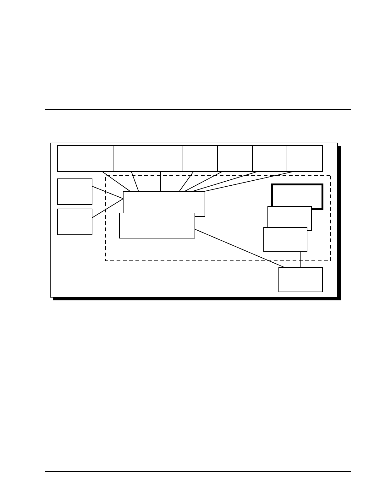
3.0 Fibre Channel standards
Figure 1 shows the various documents involved in the ANSI set of standards relating to Fibre Channel. This
model is not static—it is growing as others areas of interest are developed.
FC-SB
Mapping of Single-Byte
Command Code Sets
FC-ATM
Mapping of
ATM
FC-AE
Avionics
Environment
FC-FP
Mapping of
HIPPI-FP
Fibre Channel Enhanced Physical
Fibre Channel Physical Interface
FC-IG
Fibre Channel Implementation Guide
FC-LE
Link
Encapsulation
FC-PH-n
FC-PH
X3.230-1994
SCSI-FCP
SCSI-FC
Protocol
SCSI-GPP
Generic
Packetized
Protocol
FC-I3
Revision to
IPI-3 Disk std
Arbitrated Loop
Switch Fabric
FC-FG
General Fabric
Requirements
FC-I3
Revision to
IPI-3 Tape std
FC-AL-n
FC-SW
FC-GS
Generic Services
Figure 1. Fibre Channel standards
The interface is compatible with a subset of the ANSI standards listed below:
• SCSI-2 Standard and the Common Command Set (CCS) document, Revision 4.B
• SCSI Parallel Interface-3 (SPI-3)
• SCSI Enclosure Services (SES) Command Set, X3T10 NCITS, 305-199x
• Fibre Channel Physical and Signaling, Revision 4.3 (FC-PH)
• Fibre Channel Physical and Signaling, Revision 7.4 (FC-PH-2)
• Fibre Channel Physical and Signaling, Revision 9.4 (FC-PH-3)
• SCSI Fibre Channel Protocol, Revision 12 (SCSI-FCP)
• Fibre Channel Arbitrated Loop, Revision 4.5 (FC-AL)
• Fibre Channel Arbitrated Loop Direct Attach SCSI Technical Report
• Fibre Channel Fabric Loop Attach Technical Report
Fibre Channel Interface Manual, Rev. D 5
Page 20

Copies of ANSI documents relating to Fibre Channel can be purchased from:
Global Engineering
15 Inverness Way East
Englewood, CO 80112-5704
(800) 854-7179 or
(303) 792-2181
Fax: (303) 792-2192
3.1 General information
The FC-PH standard is the foundation upon which all others are based. Each topology, command set, and protocol has its own standard. These are all separate to allow future growth and to allow designers to more easily
use only those parts that affect their products. It is important for system designers to consider the requirements
of the set of protocols to be supported because different protocols require different subsets of the functions
permitted in a Fibre Channel port.
3.1.1 Description of Fibre Channel levels
The Fibre Channel levels are listed below:
• Physical (FC-0)
• 8B/10B encoding/decoding (FC-1)
• FC-AL (FC-1.5)
• Framing protocol (FC-2)
• Common services (FC-3)
• Interface mapping (FC-4)
3.1.1.1 FC-0
FC-0 defines the physical portions of the Fibre Channel. This includes the fibre, connectors, and optical and
electrical parameters for a variety of data rates and physical media. Coax, twinax, and twisted pair versions are
defined for limited distance applications. FC-0 also provides the point-to-point physical portion of the Fibre
Channel.
3.1.1.2 FC-1
FC-1 defines the transmission protocol which includes the serial encoding, decoding, and error control.
3.1.1.3 FC-1.5
FC-1.5 defines the topology involved with Fibre Channel Arbitrated Loop (FC-AL) configurations.
3.1.1.4 FC-2
FC-2 defines the signaling protocol which includes the frame structure and byte sequences.
3.1.1.5 FC-3
FC-3 defines a set of services which are common across multiple ports of a node.
6 Fibre Channel Interface Manual, Rev. D
Page 21

3.1.1.6 FC-4
FC-4 defines the interface mapping between the lower levels of the Fibre Channel and the various command
sets. These various command sets are known as upper layer protocols (ULPs). Examples of upper layer protocols include SCSI, IPI, HIPPI, and IP.
3.1.2 Relationship between the levels
FC-0, FC-1, and FC-2 are integrated into the FC-PH document. The other documents are separate so that
each implementation may use the technology best suited to the environment in which it will be used.
3.1.3 Topology standards
Each topology has its own standard. This is done so that designers can concentrate on documents that apply
to the technology suited to their specific area of interest.
The following topology standards are available:
• FC-FG (Fibre Channel Fabric Generic)
• FC-SW (Fibre Channel Cross-point switch)
• FC-AL (Fibre Channel Arbitrated Loop)
The FC-FG and FC-AL documents are of the most interest for Seagate disc drive interconnection.
3.1.4 FC Implementation Guide (FC-IG)
FC-IG provides some implementation guidance for all Fibre Channel systems.
Fibre Channel Interface Manual, Rev. D 7
Page 22

8 Fibre Channel Interface Manual, Rev. D
Page 23

4.0 Introduction to topologies
Topologies include all the elements necessary to successfully connect two or more nodes (also known as
devices). See Section 4.1. There are several topologies available with Fibre Channel, but all of them have certain common components: nodes, ports, and links. These components are discussed in this section.
The ANSI Fibre Channel standard defines three topologies:
1. Arbitrated loop (Fibre Channel Arbitrated Loop, FC-AL)
2. Fabric
3. Point-to-point
Seagate supports arbitrated loop and fabric as the primary topologies for disc drive connections.
Note. Some brief discussions about items not directly associated with arbitrated loop and fabric topolo-
gies are included to make you aware that other topologies exist within the constructs of the ANSI
Fibre Channel standard.
The fabric topology permits dynamic interconnections between nodes through ports connected to a fabric. This
fabric is similar to a switch or router and is often compared to a telephone system because of its redundant
rerouting capabilities. The fabric topology also allows multiple connections simultaneously, unlike FC-AL which
results in a single circuit being established between only two ports at any one particular time. Fabric and arbitrated loop topologies may be combined in one system to provide a wide variety of services and performance
levels to the nodes.
Point-to-point topologies are used only to connect two ports without any routing capabilities.
4.1 Nodes
Fibre Channel devices are called nodes. This is a generic term describing any device (workstation, printer, disc
drive, scanner, etc.) connected to a Fibre Channel topology. Each node has at least one port, called an N_Port
to provide access to other nodes. The “N” in N_Port stands for node. As you will see later, ports used in a Fibre
Channel Arbitrated Loop topology are called NL_Ports where the “NL” stands for node loop.
The components that connect two or more node ports together are what are collectively called a topology.
Nodes work within the provided topology to communicate with all other nodes.
4.2 Ports
Ports are the link to the outside world for a Fibre Channel node. See Figure 2. As stated above, each node has
at least one port to provide access to other nodes. Each Seagate Fibre Channel drive has two ports.
Each port uses a pair of fibers—one to carry information into the port and one to carry information out of the
port. This pair of fibers (actually copper wire) is called a “link” and is part of each topology. The Fibre Channel
ANSI specification also supports fibers made of optical strands as a medium for data transfer.
Fibre Channel Interface Manual, Rev. D 9
Page 24

As stated above, ports used in a FC-AL topology are called node loop ports (NL_Ports). Other port types exist
as documented in the following table.
Table 1: Fibre Channel port types
Port type Location Associated topology
N_Port Node Point-to-point or Fabric
NL_Port Node in N_Port mode—Point-to-point or Fabric
F_Port Fabric Fabric
FL_Port Fabric in F_Port mode—Fabric
E_Port Fabric Internal Fabric Expansion
G_Port Fabric in F_Port mode—Fabric
GL_Port Fabric in F_Port mode—Fabric
NL_Ports and FL_Ports discover their mode of operation dynamically during the initialization procedure.
Note. You may hear the term “L_Port” when discussing Fibre Channel. This term is often used as a
“catch-all” term meaning NL_Port or FL_Port when it is not important to specifically distinguish
between the two. Therefore, when you read the term L_Port, you should think of NL_Port when the
discussion is about Arbitrated Loop or Point-to-Point topologies, and you should think of FL_Port
when the discussion is about the Fabric topology.
in NL_Port mode—Arbitrated Loop
in FL_Port mode—Arbitrated Loop
in E_Port mode—Internal fabric expansion
in FL_Port mode—Arbitrated Loop
in E_Port mode—Internal fabric expansion
An L_Port discovers its environment and works properly, without outside intervention, with an F_Port, N_Port,
or with other L_Ports.
Arbitrated loops can have up to 126 active NL_Ports, but only one active FL_Port attached to the same arbitrated loop. The NL_Ports discover whether there is a fabric present by discovering whether there is an
FL_Port present. If there isn’t an FL_Port present, the loop is called a private loop. If there is an FL_Port
present, the loop is called a public loop and the FL_Port is considered the manager of the loop.
The most commonly used ports are the NL_Port and FL_Port. With these two types, you can easily migrate
nodes from one topology to another.
Each NL_Port is attached to one link. Information flows in one direction only.
4.3 Links
Each port is comprised of two fibers, one carries information into the port and is called a receiver. The other
carries information out of the port and is appropriately called a transmitter. Fibre Channel supports two types of
fibers—electrical wires (most commonly copper) and optical strands. This pair of wires is called a link. See Figure 2.
Links carry the data frames between nodes. Each link can handle multiple frame types; therefore, frame multiplexing is possible. For example, a frame containing SCSI information may be followed by a frame containing
TCP/IP followed by a frame containing yet another protocol’s information.
4.4 Arbitrated loop topology
Fibre Channel Arbitrated Loops (FC-AL) attach multiple nodes in a loop without hubs and switches. The node
ports use arbitration to establish a point-to-point circuit. FC-AL is a distributed topology where each L_Port
includes the minimum necessary function to establish the circuit.
10 Fibre Channel Interface Manual, Rev. D
Page 25
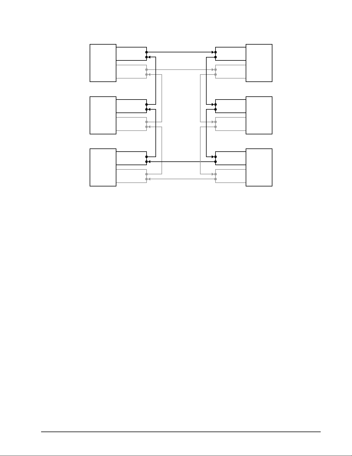
The arbitrated loop topology is used to connect from two to 126 node ports. See Figure 2.
NL_Port 6
(Fibre A)
Node A
NL_Port 6
(Fibre B)
NL_Port 5
(Fibre A)
Node F
NL_Port 5
(Fibre B)
NL_Port 4
(Fibre A)
Node E
NL_Port 4
(Fibre B)
Figure 2. Arbitrated loop topology (dual port private loop)
NL_Port 1
(Fibre A)
Node B
NL_Port 1
(Fibre B)
NL_Port 2
(Fibre A)
Node C
NL_Port 2
(Fibre B)
NL_Port 3
(Fibre A)
Node D
NL_Port 3
(Fibre B)
The ports in an arbitrated loop topology are called NL_Ports (Node Loop Ports). Each of the NL_Ports has an
input and output connection. Seagate Fibre Channel drives support dual ports (specified with a “1” in byte 6, bit
4 of the disc drive inquiry data). The actual ports are located on the host’s backpanel, not on the disc drive.
Dual ports are provided for redundancy so that if one loop fails, the other one can fulfill the loop duties. Each
drive has one FC SCA (single connector attachment) connector.
The arbitrated loop protocol is a token acquisition protocol. This means each port on the same arbitrated loop
sees all messages, but passes all messages that are addressed to other ports.
4.5 Topology and port login
Each NL_Port must sign in with the other ports on the loop. Each port first attempts to locate an FL_Port. If it
finds an FL_Port, it knows it is a part of a public loop connected to a fabric. If the port does not locate an
FL_Port, it knows it is a part of a private loop with other NL_Ports only.
There can be up to 126 active NL_Ports and up to one active FL_Port attached to the same arbitrated loop. If
an NL_Port does not attempt to discover an FL_Port and there is an FL_Port present, the NL_Port is only
allowed to access other NL_Ports on the same loop.
4.6 Port bypass circuits
So far, we’ve discussed links, ports, nodes, and topology logins. All’s fine with this model as long as the loop is
intact. What happens, then, if a device is disconnected from the loop. Doesn’t this break the loop? The answer
is no. Fibre Channel provides port bypass circuitry which bypasses the drive if it is removed, incapable of providing loop services, unable to obtain a valid address, or otherwise incapable of providing loop services. These
port bypass circuits (PBCs) are located external to the drive or other FC-AL device. Figure 3 shows the relationship between the PBC and drive.
Fibre Channel Interface Manual, Rev. D 11
Page 26
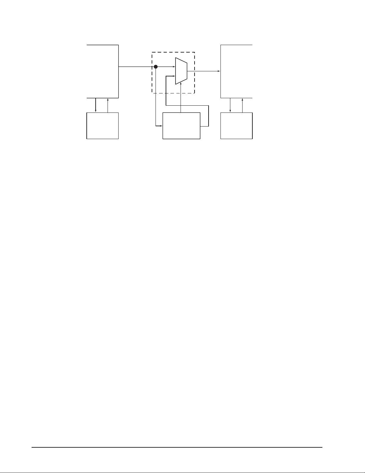
Port Bypass
From Previous
Drive
Port Bypass
Circuit N–1
Drive N–1
Figure 3. Port bypass circuit physical interconnect
Circuit
MUX
Select
SerialInSerial
Out
Drive N
To Next
Drive
Port Bypass
Circuit N+1
Drive N+1
12 Fibre Channel Interface Manual, Rev. D
Page 27
5.0 Data encoding (FC-1)
Fibre Channel devices don’t transmit 8-bit bytes. If this were to occur, the receiving node would not understand
the transmitter’s intentions. To fix this situation, the data is encoded prior to transmission. Encoding allows the
creation of special transmission code characters with unique bit patterns for data management and word alignment so the receiving node will know what to do with the bytes. Encoding also improves the transmission characteristics across a fibre and increases the likelihood of detecting errors.
5.1 Encoding and decoding
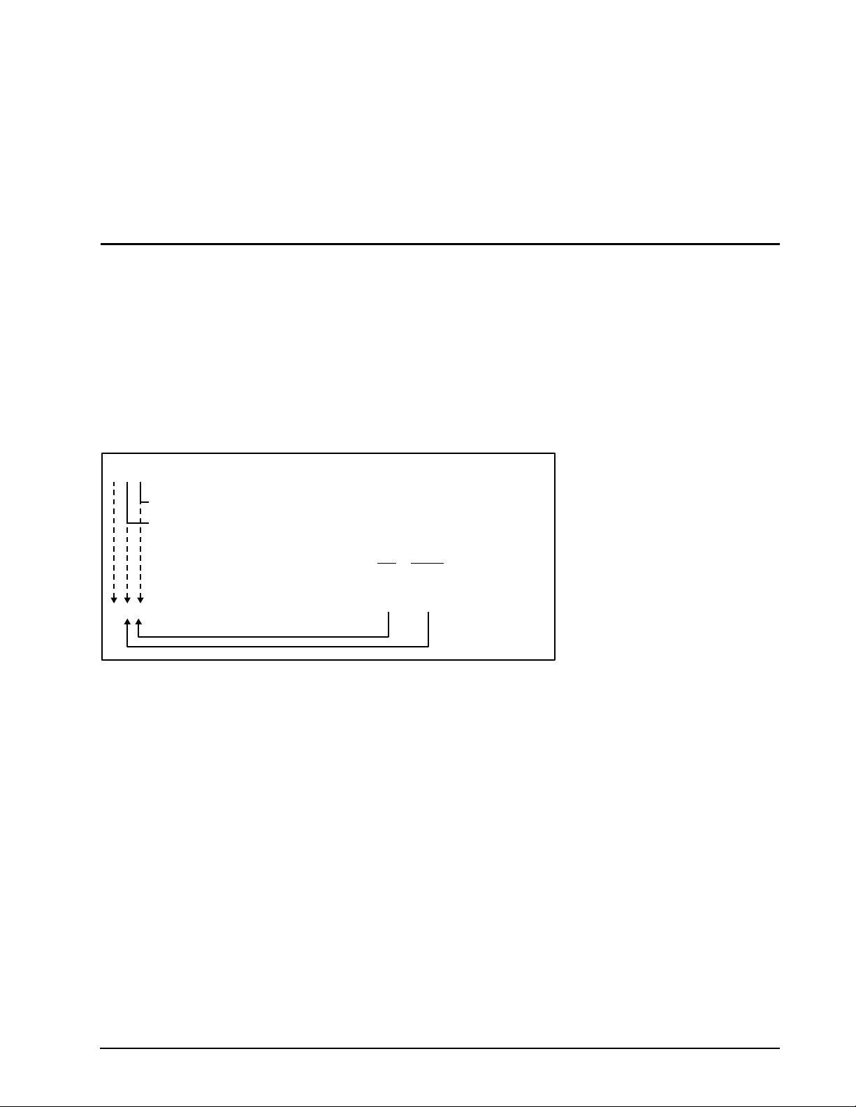
An unencoded data byte is represented in FC-1 as HGFEDCBA where H is the most significant bit. The hex to
FC-1 decimal value translation is accomplished as shown below:
Kxx.y
y = the decimal value of the most significant 3 bits (HGF)
xx = the decimal value of the least significant 5 bits (EDCBA)
y xx
Example: BCh = 10111100 (binary) = 101 11100 (binary grouped)
=
=
K28.5
Figure 4. Decimal value translation
A decimal value is assigned to each bit combination with the range of 0 to 31 for xx and 0 to 7 for y. This means
the range of valid data characters using the FC-1 naming convention is D00.0 through D31.7.
FC serial transmission delivers 10-bit characters which represent encoded data. Of the 1,024 characters possible with the 10-bit space, 256 8-bit byte data characters are mapped, along with 1 control character. This mapping process is called 8B/10B encoding. This encoding method involves selecting encoded 10-bit characters to
maintain a run-length-limited serial stream of bits. To prevent too many ones or zeros on the serial interface
from causing a DC electrical shift of the serial media, the encoder monitors the number of ones in the encoded
character and selects the option of the 10-bit encode character that will shift to balance the total number of
zeros and ones. This balancing is called running disparity.
A 10-bit character is actually made up of 6- and 4-bit sub-blocks. The 6-bit sub-block shifts out first followed by
the 4-bit sub-block. Running disparity is set positive at the end of the sub-block as follows:
• If the number of ones in a sub-block is greater that the number of zeros, the 6-bit sub-block is 000111b, or
the 4-bit sub-block is 0011b. Running disparity is set positive at the end of the sub-block.
• If the number of zeros in a sub-block is greater than the number of ones, the 6-bit sub-block is 111000b, or
the 4-bit sub-block is 1100b. Running disparity is set negative at the end of the sub-block.
5 28 (decimal values)
Fibre Channel Interface Manual, Rev. D 13
Page 28
• If the number of ones and zeros in a sub-block are equal, running disparity is neutral and the value of running disparity at the end of the sub-block remains the same as the preceding character even if it is separated
by neutral characters.
Note. The rules of running disparity prohibit consecutive positive or consecutive negative characters even
if they are separated by neutral disparity characters. In other words, the negative and positive disparity characters must alternate, even if separated by a neutral disparity character. See Table 2.
Table 2: Running disparity examples
Sub-blocks
Val id?12345
+N–+– Yes
+N+ No
++ No
–– No
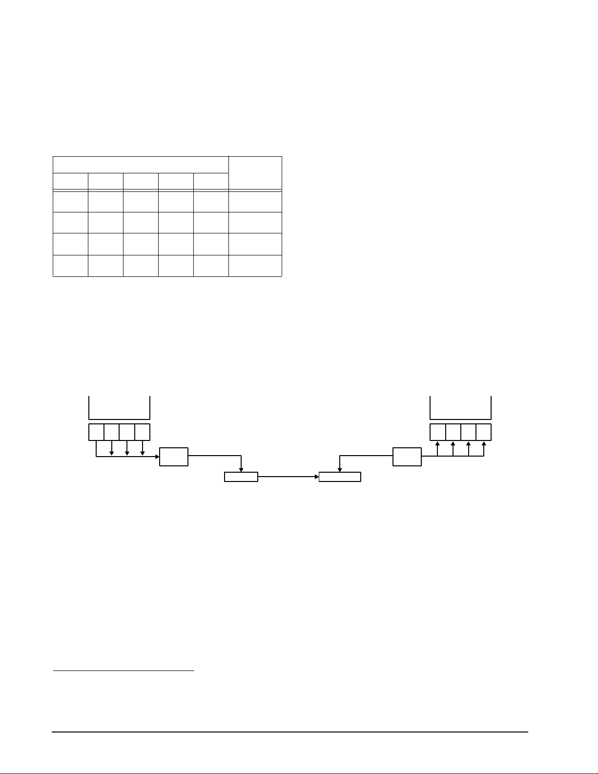
5.2 Buffer-to-buffer data transfers
Fibre Channel devices transfer information from an output buffer in the transmitting node to an input buffer of
the receiving node. This is called a buffer-to-buffer transfer. Each node may have from 1 to n buffers. The number of buffers in each node does not have to be equal. Each buffer is the size a frame may transfer in its payload. The Fibre Channel standard does not define the actual length of the buffer or the method used to store
the bytes in the buffer. Figure 5 shows how data is sent from the transmit buffer and received by the receive
buffer.
Transmit
Buffer
8-bit
8-bit
8-bit
byte
byte
8-bit character 10-bit character
byte
8-bit
byte
8B/10B
Encoder
Serializer
Serial transfer
10-bit character
Deserializer
8B/10B
Decoder
Receive
Buffer
8-bit
8-bit
byte
byte
8-bit character
8-bit
byte
8-bit
byte
Figure 5. Serialization process
The bytes being transmitted are sent in increasing displacement.1
The basic unit of transfer for the contents of a buffer-to-buffer data transfer is the frame.
1
This means that if byte 0 is sent first, bytes 1, 2, 3, and 4 are then transmitted in that order. If byte 100 is sent first, bytes
101, 102, 103, and 104 are then transmitted in that order.
14 Fibre Channel Interface Manual, Rev. D
Page 29

5.3 Data hierarchy
A hierarchy of data types is presented in Figure 6.
Transmission word (40 bits — 4 10-bit encoded bytes)
8B/10B encoded byte 1 (10 bits)
Byte (8 bits)
Bit Bit Bit Bit Bit
Figure 6. FC data hierarchy
• • •
Bit Bit Bit Bit Bit Bit Bit Bit Bit Bit
8B/10B encoded byte 4 (10 bits)
Byte (8 bits)
Bit Bit Bit Bit Bit
5.3.1 Transmission words
Transmission words are the lowest level of control on Fibre Channel other than the control character used to
provide character synchronization.
A transmission word is defined as four contiguous 8B/10B encoded transmission characters (10 bits each)
treated as a unit. This unit is 40 bits in length (4 characters x 10 bits each) and is the smallest unit of transmission in Fibre Channel.
5.3.1.1 Data characters
A data character is a 8B/10B encoded transmission character with a data byte equated by the transmission
code as one of the 256 possible data characters.
5.3.1.2 Special characters
The 8B/10B encoding scheme allows for all 256 data byte values, plus several others that can be used for special signaling. These other values are called special characters. Special characters include any transmission
character considered valid by the transmission code but not equated to a valid data byte.
5.4 Ordered sets
An ordered set is a four-character combination of data and special transmissions characters. There are three
primary categories of ordered sets:
• Primitive signals
• Primitive sequences
• Frame delimiters
The K28.5 special character is the first character of all ordered sets.
5.4.1 Primitive signals
Primitive signals are ordered sets that perform a control function. Primitive signals are recognized when one
ordered set is detected. Table 3 lists the defined primitive signals. There must be a minimum of six primitive
signals (Idles and R_RDYs) at the N_Port transmitter between frames to properly maintain clock skew.
Fibre Channel Interface Manual, Rev. D 15
Page 30

Table 3: Primitive signals
Beginning
running
Primitive signal Signal
Idle IDLE Negative K28.5 D21.4 D21.5 D21.5 BC 95 B5 B5
Receiver_Ready R_RDY Negative K28.5 D21.4 D10.2 D10.2 BC 95 4A 4A
disparity Ordered set (FC-1) Ordered set (hex)
Idle (IDLE)
An Idle is transmitted on the loop to indicate the node is operational and ready for frame transmission and
reception. Idles are transmitted when frames, R_RDY, or primitive sequences are not being transmitted. This
maintains word synchronization and minimum spacing between frames.
Receiver ready (R_RDY)
R_RDY indicates that a frame was received and that the interface buffer that received the frame is ready for
another frame. R_RDY is preceded and followed by a minimum of two Idles. R_RDY establishes buffer-tobuffer credit during data transmissions between an initiator and target.
5.4.1.1 Primitive signals used as frame delimiters
Primitive signals can also be frame delimiters. A frame is an indivisible information unit that may contain data to
record on disc or control information such as a SCSI command.
Note. All ordered sets (except for the End-of-frame delimiter, EOF) require the running disparity from the
previous word to be negative. The second character of an ordered set (except EOF) will be positive
and the third and fourth characters are neutral.
Frame delimiters mark the beginning and end of frames. There are several frame delimiters available in Fibre
Channel. There are nine Start-of-frame (SOF) delimiters and six End-of-frame (EOF) delimiters as listed in
Table 4.
Start-of-frame (SOF) delimiters:
• mark the beginning of a frame,
• indicate whether this is the first frame of the sequence, and
• indicate the class of service for the frame.
End-of-frame (EOF) delimiters:
• mark the end of a frame, and
• indicate whether this frame is the last frame of the sequence.
The second character of EOF delimiters differentiates between normal and invalid frames. The EOF delimiter
also ensures that negative running disparity results after processing the set by assigning the appropriate second character.
The third and fourth characters of the delimiter functions (SOF and EOF) are repeated to ensure that an error
affecting a single character will not result in the recognition of an ordered set other than the one transmitted.
See Table 4 below.
16 Fibre Channel Interface Manual, Rev. D
Page 31

Seagate disc drives use only those listed in bold type (Seagate Fibre Channel disc drives are Class 3 devices
and use only Class 3 delimiters).
Table 4: Frame delimiters
Beginning
running
Delimiter function Delimiter
SOF Connect Class 1 SOFc1 Negative K28.5 D21.5 D23.0 D23.0 BC B5 17 17
SOF Initiate Class 1 SOFi1 Negative K28.5 D21.5 D23.2 D23.2 BC B5 57 57
SOF Normal Class 1 SOFn1 Negative K28.5 D21.5 D23.1 D23.1 BC B5 37 37
SOF Initiate Class 2 SOFi2 Negative K28.5 D21.5 D21.2 D21.2 BC B5 55 55
SOF Normal Class 2 SOFn2 Negative K28.5 D21.5 D21.1 D21.1 BC B5 35 35
SOF Initiate Class 3 SOFi3 Negative K28.5 D21.5 D22.2 D22.2 BC B5 56 56
SOF Normal Class 3 SOFn3 Negative K28.5 D21.5 D22.1 D22.1 BC B5 36 36
SOF Initialize Loop SOFil Negative K28.5 D21.5 D22.2 D22.2 BC B5 56 56
SOF Activate Class 4 SOFc4 Negative K28.5 D21.5 D25.0 D25.0 BC B5 19 19
SOF Initiate Class 4 SOFi4 Negative K28.5 D21.5 D25.2 D25.2 BC B5 59 59
SOF Normal Class 4 SOFn4 Negative K28.5 D21.5 D25.1 D25.1 BC B5 39 39
disparity Ordered set (FC-1) Ordered set (hex)
SOF Fabric SOFf Negative K28.5 D21.5 D24.2 D24.2 BC B5 58 58
EOF Terminate EOFt Negative
Positive
EOF DisconnectTe r m in a t e
EOF Abort EOFa Negative
EOF Normal EOFn Negative
EOF DisconnectTerminate-Invalid
EOF Normal-Invalid EOFni Negative
EOFdt Negative
Positive
Positive
Positive
EOFdti Negative
Positive
Positive
K28.5 D21.4 D21.3 D21.3
K28.5 D21.5 D21.3 D21.3
K28.5 D21.4 D21.4 D21.4
K28.5 D21.5 D21.4 D21.4
K28.5 D21.4 D21.7 D21.7
K28.5 D21.5 D21.7 D21.7
K28.5 D21.4 D21.6 D21.6
K28.5 D21.5 D21.6 D21.6
K28.5 D10.4 D21.4 D21.4
K28.5 D10.5 D21.4 D21.4
K28.5 D10.4 D21.6 D21.6
K28.5 D10.5 D21.6 D21.6
BC 95 75 75
BC B5 75 75
BC 95 95 95
BC B5 95 95
BC 95 F5 F5
BC B5 F5 F5
BC 95 D5 D5
BC B5 D5 D5
BC 8A 95 95
BC AA 95 95
BC 8A D5 D5
BC AA D5 D5
Notes.
1. EOF primitives come in two forms—one is used when the beginning running disparity is positive and the
other is used if the beginning running disparity is negative. Regardless of which form is used, each EOF
delimiter is defined so that negative current running disparity results after processing the final (rightmost)
character of the ordered set.
2. Ordered sets associated with SOF delimiters, primitive signals, and primitive sequences are always transmitted with negative beginning running disparity. As a result, primitive signals, primitive sequences, and
SOF delimiters are only defined for the negative beginning running disparity case.
3. Frames that end with any other EOF type are discarded by the drive.
Fibre Channel Interface Manual, Rev. D 17
Page 32

Start-of-frame Initiate Class 3 (SOFi3)
SOFi3 indicates the beginning of the first frame of a sequence of frames (an exchange). (This includes all single frame sequences, commands, link services, transfer readys, and response frames.) SOFi3 is also used in
the first data frame of a sequence.
Start-of-frame Normal Class 3 (SOFn3)
SOFn3 indicates the beginning of any frame other than the first frame of an exchange (see SOFi3 above).
Start-of-frame Initialize Loop (SOFil)
SOFil is the same as SOFi3, but is renamed for use in Loop Initialization to remove the class of service distinction from the initialization process.
End-of-frame Normal (EOFn)
EOFn indicates the end of any frame other than the last frame of an exchange or sequence.
End-of-frame Terminate (EOFt)
EOFt marks the end of the last frame of all sequences. It can also indicate the end of the last frame of an
exchange. For example, the single frame sequences, commands, link services, transfer readys, and response
frames.
5.4.1.2 Primitive signals custom made for arbitrated loop topologies
There are eight primitive signals used exclusively within arbitrated loop (FC-AL) topologies. These primitives
are listed in Table 5 and defined in text following the table.
Table 5: FC-AL primitive signals
Beginning
running
FC-AL primitive signal Signal
Arbitrate ARBx Negative K28.5 D20.4 AL_PA AL_PA BC 94 AL_PA AL_PA
Arbitrate (F0) ARB(F0) Negative K28.5 D20.4 D16.7 D16.7 BC 94 F0 F0
Open full-duplex OPNyx Negative K28.5 D17.4 AL_PD AL_PS BC 91 AL_PD AL_PS
Open half-duplex OPNyy Negative K28.5 D17.4 AL_PD AL_PD BC 91 AL_PD AL_PD
Open broadcast replicate OPNfr Negative K28.5 D17.4 D31.7 D31.7 BC 91 FF FF
Open selective replicate OPNyr Negative K28.5 D17.4 AL_PD D31.7 BC 91 AL_PD FF
Close CLS Negative K28.5 D5.4 D21.5 D21.5 BC 85 B5 B5
Dynamic Half Duplex DHD Negative K28.5 D10.4 D21.5 D21.5 BC 8A B5 B5
Mark MRKtx Negative K28.5 D31.2 MK_TP AL_PS BC 5F MK_TP AL_PS
disparity Ordered set (FC-1) Ordered set (hex)
Arbitrate (ARBx)
ARBx is transmitted to request access to the loop. Each ARBx contains the Physical (port) Address (AL_PA) of
the requestor.
Arbitrate (ARB(F0))
ARB(F0) is transmitted to manage access fairness (see Section 8.3.1 on page 47). It is also used to assign a
loop master during initialization.
18 Fibre Channel Interface Manual, Rev. D
Page 33

Open full-duplex (OPNyx)
After successful arbitration, the transmitting port (x) opens the receiving port (y) for control and data frame
transmission and reception. Any FC port can transmit or receive an OPN.
Open half-duplex (OPNyy)
After successful arbitration, the initiator opens the target (y) for control and data frame transmission and reception of control frames. Data frame transmission from the target is not allowed.
Open broadcast replicate (OPNfr)—Not supported by Seagate drives
OPNfr is used by the open port to communicate with all ports in the loop. When received by the targets (the
opened ports), they are not allowed to generate any transmission words (except fill words). They must replicate
and retransmit all received words until a CLS is detected. Both ‘ f ’ and ‘ r ’ are FFh (D31.7 in FC-1 transmission code).
Open selective replicate (OPNyr)—Not supported by Seagate drives
Similar to OPNfr (see definition above), with the exception that the initiator can communicate with a subset of
the targets on the loop. The target at AL_PA ‘ y ’ is a member of the subset.
Close (CLS)
Close indicates that the CLS originator is prepared to or has ended the current loop circuit.
Dynamic Half Duplex (DHD)
DHD indicates the open L_Port is relinquishing control of when the current loop circuit is closed. Support of
DHD is discovered during Port Login.
Mark (MRKtx)—Not supported by Seagate drives
Mark may be used for synchronization within the loop (for example, spindle sync in a RAID application). The
third character of the ordered set ‘ t ’ (MK_TP) is a vendor-unique sync code. Seagate drives pass through this
primitive signal without responding to it.
5.4.2 Primitive sequences
Primitive sequences are ordered sets that perform control functions. These primitive sequences are listed in
Table 6. Primitive sequences differ from primitive signals in the requirement for detection. Primitive sequences
must have at least three consecutive ordered sets to be detected. Primitive sequences are transmitted repeatedly.
All of these primitive sequences are defined in Fibre Channel, but are not recognized by the drive. The Loop
Initialization Primitive (LIP) sequence is used in arbitrated loop configurations to reset all attached ports to a
known state. Refer to Section 8.2 on page 35 for additional information about LIPs.
Fibre Channel Interface Manual, Rev. D 19
Page 34

Table 6: Primitive sequences
Beginning
running
Primitive sequences Sequence
Offline OLS Negative K28.5 D21.1 D10.4 D21.2 BC 35 8A 55
Not_Operational NOS Negative K28.5 D21.2 D31.5 D5.2 BC 55 BF 45
Link_Reset LR Negative K28.5 D9.2 D31.5 D9.2 BC 49 BF 49
Link_Reset_Response LRR Negative K28.5 D21.1 D31.5 D9.2 BC 35 BF 49
disparity Ordered set (FC-1) Ordered set (hex)
Offline (OLS)
Offline is transmitted to indicate that the port is initiating the initialization protocol prior to going offline. The
sequence will be transmitted for a minimum of 5 msec before further action is taken.
Not_Operational (NOS)
Not_Operational is transmitted to indicate that the port has detected a loop failure or is offline.
Link_Reset (LR)
Link_Reset is transmitted by a port to initiate the Link Reset protocol following a Link Timeout. This brings the
port back to a stable synchronized state.
Link_Reset_Response (LRR)
Link_Reset_Response is transmitted to indicate that the port is receiving and recognizes the Link_Reset (LR)
primitive sequence.
5.4.2.1 Primitive sequences custom made for Arbitrated Loop topologies
There are eight primitive sequences used exclusively within arbitrated loop (FC-AL) topologies. These primitives are listed in Table 7 and defined in text following the table.
Table 7: FC-AL primitive sequences
Beginning
running
FC-AL primitive sequence Sequence
Loop initialization,
no valid AL_PA
Loop initialization,
loop failure, no valid AL_PA
Loop initialization,
valid AL_PA
Loop initialization,
loop failure, valid AL_PA
Loop initialization reset LIP Negative K28.5 D21.0 AL_PD AL_PS BC 15 AL_PD AL_PS
Loop initialization reset all LIP Negative K28.5 D21.0 D31.7 AL_PS BC 15 FF AL_PS
Loop port enable LPEyx Negative K28.5 D5.0 AL_PD AL_PS BC 05 AL_PD AL_PS
Loop port enable all LPEfx Negative K28.5 D5.0 D31.7 AL_PS BC 05 FF AL_PS
Loop port bypass LPByx Negative K28.5 D9.0 AL_PD AL_PS BC 09 AL_PD AL_PS
Loop port bypass all LPBfx Negative K28.5 D9.0 D31.7 AL_PS BC 09 FF AL_PS
LIP Negative K28.5 D21.0 D23.7 D23.7 BC 15 F7 F7
LIP Negative K28.5 D21.0 D24.7 D23.7 BC 15 F8 F7
LIP Negative K28.5 D21.0 D23.7 AL_PS BC 15 F7 AL_PS
LIP Negative K28.5 D21.0 D24.7 AL_PS BC 15 F8 AL_PS
disparity
Ordered set (FC-1)
Ordered set (hex)
20 Fibre Channel Interface Manual, Rev. D
Page 35

Note. There are six sequences that invoke loop initialization. There is no operational difference between
them except that bytes 3 and 4 identify the reason for the loop initialization.
Loop initialization, no valid AL_PA (LIP)
The L_Port is attempting to acquire an AL_PA.
Loop initialization, loop failure, no valid AL_PA (LIP)
The transmitting L_Port detects a loop failure at its receiver. Since it has not completed initialization, it uses ‘F7’
(D23.7) rather than a valid AL_PA.
Loop initialization, valid AL_PA (LIP)
The L_Port is attempting to reinitialize the loop to a known state after recognizing a problem (performance degradation).
Loop initialization, loop failure, valid AL_PA (LIP)
The transmitting L_Port detects a loop failure at its receiver.
Loop initialization reset (LIP)
If the rightmost two bytes consist of a valid destination and source address, the source is requesting the target
to perform a device reset.
Loop initialization reset all (LIP)
If byte 3 is FFh and byte 4 is a valid source address, the source is requesting all receiving targets to perform a
device reset.
Loop port enable (LPEyx)
LPEyx resets the bypass circuit and enables a previously-bypassed L_Port.
Loop port enable all (LPEfx)
LPEfx resets the bypass circuits on all L_Ports on the loop.
Loop port bypass (LPByx)
LPByx activates the port bypass circuit and prevents the L_Port from actively participating on the loop.
Loop port bypass all (LPBfx)
LPBfx activates the port bypass circuit for all L_Ports on the loop with bypass circuits except for the source of
the LPBfx.
Fibre Channel Interface Manual, Rev. D 21
Page 36

22 Fibre Channel Interface Manual, Rev. D
Page 37

6.0 Framing protocol (FC-2)
The entire responsibility of moving frames between N_Ports is assigned to the Fibre Channel layer called the
framing protocol (FC-2). This protocol is primarily concerned with constructing and managing frames,
sequences, and exchanges.
Navigation assistance
The field descriptions that are provided for most tables have sidebar labels
which identify the table they are associated with. This helps orient you when
nested tables occur within a section.
Sidebar example
Tab le
6.1 Frames
Field definitions (listed alphabetically)
number
1
Field name
The sidebar (black background with reversed text) identifies this field as being associated with Table 1.
Frames transfer all information between nodes. The frames are normally constructed by the transmitting
node’s N_Port. A frame is the smallest unit of information transfer across a link. A sequence is one or more
frames. An exchange is one or more sequences. See Figure 7 below.
It is possible, but not common, for a sequence to have only one frame and for an exchange to have only one
sequence. Again, this isn’t common, but possible. Most sequences have more than one frame, and most
exchanges have more than one sequence.
Frame 1 Frame 2
Figure 7. Relationship between frames, sequences, and exchanges
Frame... Frame n Frame 1 Frame 2
Sequence 1
Frame... Frame n Frame 1 Frame 2
Sequence 2
Exchange 1 Exchange 2...
Frame... Frame n
Sequence n
6.1.1 Frame structure
A frame is a string of transmission words containing data bytes. Every frame is prefixed by a start-of-field
(SOF) delimiter and suffixed by an end-of-field (EOF) delimiter. There are never any primitive signals or primitive sequences in a frame.
Fibre Channel Interface Manual, Rev. D 23
Page 38

All frames also have a header and a Cyclic Redundancy Check (CRC) field. The payload data field is optional
(but normally present) with the size and contents determined by the type of frame.
Bytes
Words
Transmission
Words
Fill
4 24 0 to 2112 4 4 24
Frame Header Payload Data Field CRCFill Bytes EOF
SOF
1 6 0 to 528 1 1 6
Fill
Words
Figure 8. Frame structure
6.1.1.1 Start-of-frame (SOF) delimiter
Start-of-frame (SOF) delimiters signal the beginning of a frame. See “Frame delimiters” on page 17. This referenced page contains a list of the various types of SOF delimiters.
6.1.1.2 Frame header
The frame header is 24 bytes long and is present in all frames. It is used to control link operation, control
device protocol transfers, and to detect missing frames or frames that are out of order.
Table 8: Frame header format
Byte
Word
0R_CTL D_ID
1 Reserved S_ID
2Type F_CTL
3 SEQ_ID DF_CTL SEQ_CNT
0
(bits 31 - 24)
1
(bits 23 - 16)
2
(bits 15 - 08)
3
(bits 07 - 00)
4 OX_ID RX_ID
5
Tab le
Field definitions (listed alphabetically)
number
8
DF_CTL (Data Field Control)
Offset
Specifies the presence of optional headers in the payload of the frame. The drive does not support optional headers.
00h The drive sets this field to 00h for all frames it originates (sends), and should also be 00h for all frames sent to the
drive.
8
D_ID (Destination Identifier)
The 3-byte N_Port address to which the frame is being sent.
24 Fibre Channel Interface Manual, Rev. D
Page 39

F_CTL (Frame Control)
8
This 3-byte (24-bit) field contains control information relating to the frame content as defined below.
Table 9: Frame Control (F_CTL) bit definitions
Bit Definition Description
Exchange context 0 = Frame is from the exchange originator.
23
Sequence context 0 = Initiator
22
First sequence 0 = Not the first sequence of the exchange.
21
Last sequence 0 = Not the last sequence of the exchange.
20
End of sequence 0 = Not the last frame of the sequence.
19
End connection
18
Chained sequence
17
Sequence initiative 0 = Hold sequence initiative.
16
X_ID reassigned
15
Invalid X_ID
14
Reserved
13
12
11
10
Retransmitted
9
sequence
Unidirectional
8
transmit
Continue sequence
7
condition
6
Abort sequence
5
condition
4
Relative offset
3
present
Reserved
2
Fill data bytes End of data field fill bytes
1
0
1 = Frame is from the exchange responder.
1 = Recipient
1 = First sequence of the exchange.
1 = Last sequence of the exchange.
1 = Last frame of the sequence.
Not supported.
Not supported.
1 = Transfer sequence initiative.
Not supported.
Not supported.
Not supported.
Not supported.
Not supported.
Not supported.
0 = Parameter field not meaningful.
1 = Parameter field equals relative offset.
00 = 0 bytes of fill.
01 = 1 byte of fill (last byte of data field).
02 = 2 bytes of fill (last 2 bytes of data field).
03 = 3 bytes of fill (last 3 bytes of data field).
8
Offset
This 4-byte field is used in data frames to define the relative offset (displacement) of the first byte of the payload from the
base address of the command. When the relative offset is present, bit 3 of F_CTL is set to indicate that relative offset is
valid.
The drive uses the SEQ_CNT value to verify that frames are being received in order. The drive does not use relative offset
in frames it receives. The drive sends relative offset information in data frames it originates.
Fibre Channel Interface Manual, Rev. D 25
Page 40

OX_ID (Originator Exchange Identifier)
8
This 2-byte field is assigned by the originator of an exchange. For SCSI FCP frames, this value is analogous to the Queue
Tag used in Parallel SCSI and must be unique for an initiator/drive pair.
8
R_CTL (Routing Control)
This one-byte field provides routing bits and information bits to categorize the frame function.
The high order bits (bits 31-28) indicate the frame type as indicated below:
0000 = FC-4 Device_Data frame
0010 = Extended Link_Data frame
0011 = FC-4 Link_Data frame
0100 = Video_Data frame
1000 = Basic Link_Data frame
1100 = Link_Control frame
Others = Reserved
The low order bits (bits 27-24) contain the Information field values. This is dependent on the value of the high order bits (31-
28). If the high order bit value = 1000, the Information field contains a basic link service. For all other high order bit values,
the Information field specifies the Common Information Categories specified in the table below.
Table 10: Routing Control values
High order bits Low order bits Use
Type 08h, SCSI FCP, Device Data frames
0000 Uncategorized Not supported
0001 Solicited Data Read and write data
0010 Unsolicited Control Not supported
0011 Solicited control Not supported
0000
0100 Unsolicited data Not supported
0101 Data descriptor Transfer ready
0110 Unsolicited command Command
0111 Command status Response
Type 01h, Extended link service
0000 Uncategorized Not supported
0001 Solicited data Not supported
0010 Unsolicited control Request
0011 Solicited control Reply
0010
0100 Unsolicited data Not supported
0101 Data descriptor Not supported
0110 Unsolicited command Not supported
0111 Command status Not supported
Type 00h, Basic link service
26 Fibre Channel Interface Manual, Rev. D
Page 41
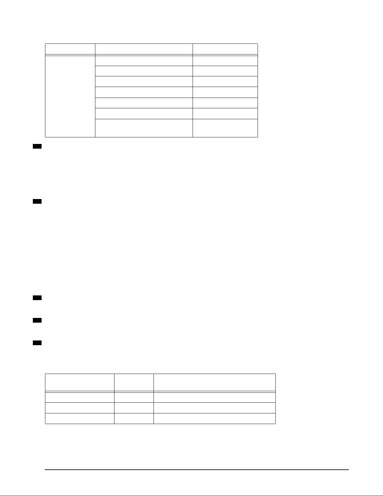
Table 10: Routing Control values (Continued)
High order bits Low order bits Use
0000 No operation Not supported
0001 Abort sequence (ABTS) Request
0010 Remove connection Not supported
1000
0011 Reserved Not supported
0100 Basic_Accept (BA_ACC) Reply
0101 Basic_Reject (BA_RJT) Reply
01100111
8
RX_ID (Responder Exchange Identifier)
Reserved Not supported
This 2-byte identifier is a unique identifier generated by the responder for an exchange established by an originator and
identified by an OX_ID.
With Class 3 devices such as this drive, the responder of the exchange assigns a unique value for RX_ID other than FFFFh
if RX_ID is being used in an ACK to a data frame in the first sequence transmitted as a sequence initiator.
The drive returns FFFFh in this field to indicate the RX_ID is not being used.
8
SEQ_CNT (Sequence Count)
This 2-byte field identifies the sequential order of frames within a sequence or multiple sequences of the same exchange.
The SEQ_CNT value for each frame of a sequence has to be unique. The field range limits the number of frames per
sequence to a maximum of 65,536.
For SCSI FCP write data transfers that require more than one sequence to transfer the data, the first frame of each
sequence starts with a SEQ_CNT of 0000h. The transfer of sequence initiative between write data sequences and the
XFR_RDY sent by the drive give the sequence originator (the SCSI Initiator) verification that the previous sequence is
closed.
For SCSI FCP read data transfers that require more than one sequence to transfer the data, the SEQ_CNT does not reset
to 0000h for each new sequence. The SEQ_CNT increments sequentially across the sequence boundaries. The
SEQ_CNT is still allowed to increment through all 65,536 possible values for each sequence. This is required as there is no
verification in Class 3 that all the frames of previous sequences have been delivered.
8
SEQ_ID (Sequence Identifier)
This field uniquely identifies frames in a non-streamed sequence or when only one sequence is open.
8
S_ID (Source Identifier)
The 3-byte address of the N_Port or F_Port originating the frame.
8
Type (Data Structure Type)
This 1-byte field identifies the protocol of the frame contents as described below:
Table 11: Data type codes
R_CTL
(4 highest order bits)
1000 00 Basic Link Service
0010 01 Extended Link Service
0000 08 SCSI FCP
Type code Description
Fibre Channel Interface Manual, Rev. D 27
Page 42

6.1.1.3 Data field (payload)
The data field, also known as the payload, is aligned on word boundaries. The payload length must be an integer multiple of four bytes and is limited to 2,112 bytes. If the data field is not an integer multiple of four bytes,
valid fill bytes are inserted to meet the requirement. F_CTL bits 0 and 1 indicate how many fill bytes are used.
Fill bytes are only permitted in the last frame of a sequence. These fill bytes can be any valid byte value.
The contents of the frame payload is specified by the type of frame. Refer to Section 9.0 for link service information.
6.1.1.4 CRC field
The Cyclic Redundancy Check (CRC) is a 4-byte field that follows the payload field. The CRC is used to verify
the integrity of the frame header and payload fields. This helps detect errors in a frame. The SOF and EOF
frame delimiters are not included in the CRC calculation.
The algorithm used to calculate the CRC field value is the same as that used in the Fiber Distributed Data
Interface (FDDI) standard. The polynomial for the CRC is:
32
x
+ x26 + x23 + x22 + x16 + x12 + x11 + x10 + x8 + x7 + x5 + x4 + x2 + x + 1
6.1.1.5 End-of-frame (EOF) delimiter
End-of-frame (EOF) delimiters signal the end of a frame. See “Frame delimiters” on page 17. This page contains a list of the various types of EOF delimiters.
6.2 Frame sequences
Since the data field has a maximum length of 2,112 bytes (528 transmission words), larger amounts of data
must be split into several frames.
Frame sequences always contain at least one frame. The frame header subfields in the F_CTL field are used
to identify the beginning, middle, and end of a frame sequence. The SEQ_ID and SEQ_CNT fields are used to
identify the order of the frames for reassembly in the event they arrive out of order at the destination when participating in a fabric topology.
The OX_ID and RX_ID fields identify the larger context (the exchange) of which this frame sequence is a part.
The frame sequence itself may be part of an exchange and is identified by the SEQ_ID field in the frame
header. The R_CTL field of the frame header identifies the category of information in all the frames of the
sequence. All of the frames within the same sequence are required to have the same category.
6.3 Exchanges
Exchanges are an additional layer that controls operations across Fibre Channel. An exchange provides a control environment for the transfer of information between two N_Ports. You can think of exchanges as an operating system that controls communications between nodes when two or more sequences are required to transmit
data or commands. Exchanges even keep track of operations that occur in opposite directions (sender to
receiver and receiver to sender). Here’s a short explanation of how this occurs:
One of the N_Ports establishes an exchange by sending a sequence to the other N_Port with at least one
frame in it. The originator names its resources using the OX_ID field in the frame header of each frame of the
exchange.
The responder of the exchange also allocates resources after it receives the first frame of the first sequence. It
names its resources using the RX_ID field.
28 Fibre Channel Interface Manual, Rev. D
Page 43

These two independent fields (OX_ID and RX_ID) allow each N_Port to identify the resources needed to manage a frame or sequence as it arrives. Each N_Port involved with the exchange can use a link service request
to view the contents of the control information in the other port in the exchange; however, no other N_Ports are
allowed to request information for the exchange since they are not involved with that particular exchange.
Command
Write Data
Exchange
Write Data
SCSI Write
Initiator
Command Transfer
Initiator
Target
Arb
Transfer Ready
Optional
Transfer
Ready’s
Response
Target
Command
Exchange
Response Transfer
Initiator
Initiator
Arb
SCSI Read
Target
Read
Data
Optional
Read
Data
Response
Target
OPN
RDY/s
Command
CLS
Figure 9. FC–SCSI exchanges, command and response transfers
OPN
RDY/s
Response
CLS
6.4 Credit
The framing protocol must be concerned about how many frames one source N_Port can send to another without overflowing the buffers in the receiving N_Port. To address this problem, there are two types of credit:
1. Buffer-to-buffer credit (BB_Credit). This type of credit is associated only with the immediate fiber exiting the
transmitter to the next receiver (F_Port or N_Port). This credit is managed by the R_RDY primitive signal
on a link.
2. End-to-end credit (EE_Credit). This type of credit is negotiated between a source N_Port and a destination
N_Port. This credit is managed using an acknowledgment (ACK) frame sent from the destination back to
Fibre Channel Interface Manual, Rev. D 29
Page 44

the source N_Port. This type of credit is not used in Class 3 therefore it is not applicable to Seagate drives.
30 Fibre Channel Interface Manual, Rev. D
Page 45

7.0 Classes of service (FC-2)
There are five classes of service currently available or being defined. Classes of service are simply different
communication methods used between nodes. Seagate drives use only Class 3; however, brief explanations of
the other classes are provided as well.
7.1 Class 1
Class 1 is like a direct face-to-face meeting with no interruptions or delays. It is a dedicated full-bandwidth connection between two nodes.
Other Class 1 attributes
• Guaranteed delivery
• Frames are received in the order they are transmitted
• Usually uses the least overall bandwidth
• Very little software interaction
7.2 Class 2
Class 2 is like an electronic mail transaction where each message has an acknowledgment message sent from
the receiver to signal that the message was received successfully. This class of service allows one N_Port to
transmit consecutive frames to multiple destinations without establishing a dedicated connection with any specific N_Port and also allows one N_Port to receive consecutive frames from one or more N_Ports without having established dedicated connections with any of them.
Other Class 2 attributes
• Confirmed delivery (the receiver sends an acknowledgment on receipt)
• Frames are not always guaranteed to be received in the order they are transmitted
• Can potentially use more bandwidth than Class 1 and latency may increase by waiting for acknowledgments
7.3 Class 3
Class 3 service multiplexes frames at frame boundaries to or from one or more N_Ports without acknowledgment of receipt.
Seagate drives use Class 3 exclusively. Class 3 reduces the complexity of the ports and provides better performance for disc applications.
Other Class 3 attributes
• Full duplex transfers may be used between two ports using Class 3; however, Class 3 operation does not
require half duplex operation.
• Acknowledge (ACK) buffer not required (no waiting for ACKs)
Fibre Channel Interface Manual, Rev. D 31
Page 46

• EE_Credit not required
• Busy and Reject not needed due to alternate credit model
• Errors are recovered at the exchange level
7.3.1 Class 3 flow control
Class 3 flow control is a simple model which does not require EE_Credits. With Class 3, there is only buffer-tobuffer flow control in one direction and there are no link level responses to Class 3 frames.
7.4 Classes 4 and 5
Classes 4 and 5 are being defined by Fibre Channel committees to aid audio and video applications.
Class 4 is similar to Class 1 in that a dedicated connection is established; however, with Class 4, the full bandwidth is not available. Connections for other nodes connected may be assigned portions of the bandwidth.
Class 5 provides isochronous service through a fabric. A Class 5 node is guaranteed access through a fabric
at established time intervals.
32 Fibre Channel Interface Manual, Rev. D
Page 47

8.0 FC Arbitrated Loop concepts
This section describes some basic Fibre Channel Arbitrated Loop (FC-AL) concepts. Seagate disc drives support FC-AL as the topology for connectivity in Fibre Channel environments.
Fibre Channel is a serial data channel that provides logical point-to-point service to two communicating
devices. With FC-AL, you can have a maximum of one point-to-point circuit at any one time. When this circuit
is active, only two L_Ports are communicating, but up to 127 devices may be attached to and participating on
the same loop. All of the L_Ports that are on the loop but that are not one of the two communicating L_Ports
“see” all data transferred across the loop and retransmit this information so that the data reaches its intended
destination.
8.1 Arbitrated Loop physical address (AL_PA)
Each device communicating on an arbitrated loop must have an Arbitrated Loop Physical Address (AL_PA).
The AL_PA is an 8-bit (1-byte) 8B/10B encoded value that is a valid data character. This 8-bit character, when
encoded to 10 bits, must have an equal number of 1’s and 0’s in the address to maintain neutral running disparity. Neutral running disparity is required so that the AL_PA data character does not change the current running disparity of the current transmission word. There are 134 characters that result in neutral disparity. See
Table 12. Seven of the 134 neutral disparity characters are reserved (see Table 13 on page 35). This leaves
127 valid addresses.
Table 12: 8B/10B characters with neutral disparity
D xx.y y
xx 01234567
* * * 00, 80, E0
00
* * * 01, 81, E1
01
* * * 02, 82, E2
02
03
04
05
06
07
08
09
* * * * * 23, 43, 63, A3, C3
* * * 04, 84, E4
* * * * * 25, 45, 65, A5, C5
* * * * * 26, 46, 66, A6, C6
* * * * * 27, 47, 67, A7, C7
* * * 08, 88, E8
* * * * * 29, 49, 69, A9, C9
Hex value
Fibre Channel Interface Manual, Rev. D 33
Page 48

Table 12: 8B/10B characters with neutral disparity
D xx.y y
xx 01234567
10
11
12
13
14
15
16
17
18
19
20
21
22
23
24
* * * * * 2A, 4A, 6A, AA, CA
* * * * * 2B, 4B, 6B, AB, CB
* * * * * 2C, 4C, 6C, AC, CC
* * * * * 2E, 4E, 6E, AE, CE
* * * * * 2E, 4E, 6E, AE, CE
* * * 0F, 8F, EF
* * * 10, 90, F0
* * * * * 31, 51, 71, B1, D1
* * * * * 32, 52, 72, B2, D2
* * * * * 33, 53, 73, B3, D3
* * * * * 34, 54, 74, B4, D4
* * * * * 35, 55, 75, B5, D5
* * * * * 36, 56, 76, B6, D6
* * * 17, 97, F7
* * * 18, 98, F8
Hex value
R
R
R
25
26
27
28
29
30
31
To t al
* * * * * 39, 59, 79, B9, D9
* * * * * 3A, 5A, 7A, BA, DA
* * * 1B, 9B, FB
R
* * * * * 3C, 5C, 7C, BC, DC
***1D, 9D, FD
* * * 1E, 9E, FE
* * * 1F, 9F, FF
R
R
R
13 19 19 19 13 19 19 13
134
* character with neutral disparity.
R
Reserved (see Table 13 on page 35).
Of the 134 neutral disparity characters, seven are reserved. This leaves 127 valid non-reserved addresses.
126 of these addresses may be used by NL_Ports and one (00) may be used by a FL_Port (if present).
34 Fibre Channel Interface Manual, Rev. D
Page 49

Table 13: AL_PA addressing
Values (hex) Use
00 Reserved for the FL_Port (if present)
01-EF Contains 127 valid addresses
F0 Reserved for fairness
F1-F6 These values do not have neutral running disparity
F7-F8 Reserved for loop initialization
FB, FD, and FE Reserved for future use
FF Reserved to address all ports in broadcast mode
In the parallel SCSI world, the higher the bus address, the higher the priority the device has. The opposite is
true with FC-AL. See Table 14.
Table 14: AL_PA value priorities
AL_PA value Priority
00 Highest priority (assigned to the FL_Port if present)
01 Highest priority NL_Port (on a public loop)
EF Lowest priority NL_Port address
F0 Used only by the fairness algorithm and has no priority
During loop initialization, each NL_Port interested in participating on the loop is assigned one of the 126 AL_PA
values. If an NL_Port is offline because its node is powered off, the port is considered a non-participating
NL_Port.
One more reason exists for an L_Port being in non-participating mode; you can place more than 127 L_Ports
on a loop, and, if this occurs, loop initialization permits only the first 126 NL_Ports and the first FL_Port to
acquire a valid AL_PA. The remaining L_Ports must wait for a position to open up to obtain a valid AL_PA.
An L_Port can get a valid AL_PA in four ways:
1. Assigned by the fabric (if present)
2. Use the previously-assigned address
3. Hard assigned by the backpanel
4. Soft assigned and acquired through the loop initialization process
The most common method that disc drives use is to have the backpanel provide a hard assigned address. This
is similar to setting a SCSI ID on a drive, but with Fibre Channel, the ID is set on the backpanel rather than the
drive. If, for some reason, a duplicate address is encountered when hard-assigned addresses are processed,
the drive will revert to acquiring a soft-assigned AL_PA during initialization. This insures that every node gets a
unique AL_PA.
A more detailed explanation of loop initialization is provided in the following section.
8.2 Loop initialization
Loop initialization is the process used to obtain or verify AL_PAs. Loop initialization occurs at power-up, when
a new node is inserted in the loop, or for error recovery.
During loop initialization, each NL_Port discovers that it is connected in an arbitrated loop topology and that
there may be multiple NL_Ports on the arbitrated loop. The procedure used for this discovery is called the loop
port state machine (LPSM). The FC-2 protocol is also used.
Fibre Channel Interface Manual, Rev. D 35
Page 50

A buffer on the drive receives each of the following loop initialization frames: LISM, LIFA, LIPA, LIHA, LISA,
LIRP, and LILP. All other frames may be discarded if the L_Port’s buffer is full.
If the NL_Ports finds that there are not any more NL_Ports attached, but that there is only an F_Port or N_Port
attached, the NL_Port configures itself to operate as an N_Port by going into N_Port mode.
An L_Port begins the loop initialization procedure in the initializing state at the request of the node. In most
cases, the backpanel will be set to provide a hard assigned physical address which will not be changed by the
initialization process, unless duplicate hard assigned physical addresses are found. The AL_PA of the one
FL_Port (if present) is always 00h. All other AL_PA values will range from 01h - EFh.
Start_of_Frame delimiter (4 bytes)
SOFil
Frame_Header (24 bytes)
22xxxxxx
where ‘xxxxxx’ is hex ‘000000’ for an FL_Port and hex ‘0000EF’ for an NL_Port.
Payload (12, 20, or 132 bytes)
Loop
Initialization
Identifier*
*The loop initialization identifier is one of the following:
11010000h = LISM — Select master based on 8-byte Port_Name (12-byte payload with an 8-byte Port_Name)
11020000h = LIFA — Fabric Assigned AL_PA bit map (20-byte payload with a 16-byte AL_PA bit map)
11030000h = LIPA — Previously-acquired AL_PA bit map (20-byte payload with a 16-byte AL_PA bit map)
11040000h = LIHA — Hard Assigned AL_PA bit map (20-byte payload with a 16-byte AL_PA bit map)
11050000h = LISA — Soft Assigned AL_PA bit map (20-byte payload with a 16-byte AL_PA bit map)**
11060000h = LIRP — Report AL_PA position map (132-byte payload with a 128-byte AL_PA position map)
11070000h = LILP — Loop AL_PA position map (132-byte payload with a 128-byte AL_PA position map)
00xxxxxx 01380000
8-byte Port_Name
16-byte AL_PA bit map
128-byte AL_PA position map (1-byte offset followed by up to 127 AL_PAs)
LIFA is used to gather all fabric-assigned AL_PAs.
LIPA is used to gather all previously-acquired AL_PAs.
LIHA is used to gather all hard assigned AL_PAs (usually set with configuration jumpers
on the host backpanel).
LISA is used to assign any remaining AL_PA bits.
LIRP is used to record the relative positions of all L_Ports on the loop.
LILP is used to inform all L_Ports of their relative positions on the loop
from the perspective of the loop master.
00000000 FFFFFFFF 00000000
**LISA contains the AL_PA mapping field in byte 2 (01h) to indicate that all L_Ports are able to enter
their position into the LIRP AL_PA position map. The 01h value in byte 2 may be changed to 00h
to bypass the LIRP and LILP sequences.
Cyclic Redundancy Check (4 bytes)
CRC
End_of_Frame delimiter (4 bytes)
EOFt
Figure 10. Loop initialization sequences
36 Fibre Channel Interface Manual, Rev. D
Page 51

The loop initialization process begins when any NL_Port forces the loop into the INITIALIZING state. See Figure 11. This initializing port begins transmitting loop initialization primitive sequences (LIPs). Any NL_Port can
cause this by sending any of the LIPS listed in Table 15. All LIPs cause the 4-step initialization process to
occur. A loss of signal will also force the loop to initialize.
There are five Loop Initialization Primitive (LIP) sequences:
Table 15: Loop Initialization Primitive (LIP) sequences
LIP Reason Code Use Description
F7, F7 Initializing LIP Used when an L_Port wants to acquire an AL_PA.
F8, AL_PS Loop failure The originating L_Port has detected an input failure. The
AL_PS is the AL_PA of the L_Port.
F8, F7 Loop failure The originating L_Port has detected an input failure but the
L_Port does not have an AL_PA.
F7, AL_PS Performance degradation The originating L_Port has detected poor loop performance.
Example: The L_Port is unable to win arbitration.
AL_PD, AL_PS Selective reset The source L_Port (AL_PS) wants to reset the destination
port (AL_PD). All L_Ports complete loop initialization. The
selected L_Port performs a reset after loop initialization.
FF, AL_PS Reset all The source L_Port (AL_PS) wants to reset all other L_Ports
supporting LIP reset on the loop. All L_Ports complete initialization. The L_Ports supporting LIP reset all (generally only
the targets in a storage implementation) perform a reset after
loop initialization.
The next L_Port in the loop receives the LIPs and transitions to the OPEN_INIT state and transmits LIPs to the
next L_Port on the loop. This cycle continues until the port that started the initialization process receives the
LIPs. It then also transitions to the OPEN_INIT state. This means all L_Ports on the loop are in the OPEN_INIT
state at this point.
Each port transmits a minimum of 12 LIPs and then transmits Idles for the AL_TIME (15 msecs). The L_Port
then transmit Loop Initialization Select Master (LISM) frames to select a loop master who will then control the
initialization process.
Loop initialization steps
There are four primary steps involved in initializing the loop.
1. Select a loop master based on the 8-byte port name (Loop Initialization Select Master—LISM).
2. Assign each port an arbitrated loop physical address (AL_PA). There are four ways a port can acquire an
AL_PA. These are listed below.
• Fabric assigned (Loop Initialization Fabric Assigned—LIFA)
• Previously acquired (Loop Initialization Previously Acquired—LIPA)
• Hard assigned (Loop Initialization Hardware Assigned—LIHA)
• Soft assigned (Loop Initialization Soft Assigned—LISA)
3. Generate AL_PA position map (Loop Initialization Report Position—LIRP).
4. Transmit completed AL_PA position map around the loop (Loop Initialization Loop Position—LILP).
Fibre Channel Interface Manual, Rev. D 37
Page 52

Loop Initialization Select Master (LISM)
12-byte payload
11010000 8-byte port name
The loop master is determined as follows:
• Each NL_Port selects an initial AL_PA of ‘EF’. The FL_Port (if present) selects an AL_PA of ‘0’.
• Each port transmits LISM with the D_ID and S_ID fields of the header set to its AL_PA. The payload is set to
the port name which includes the world wide name (WWN).
• Each port examines the payload in the inbound LISM. If it is greater than its own, the port transmits a new
LISM with its own port name in the payload. If it is less than its own, the port retransmits the received LISM.
If it is the same as its own, it becomes the loop master.
• The loop master sends ARB(F0) to purge the loop and to inform all other ports that a master has been
selected. When the master receives ARB(F0) on the inbound fibre, initialization proceeds to LIFA.
Loop Initialization Fabric Assigned (LIFA)
20-byte payload
11020000 16-byte bit map of AL_PAs
The loop master primes the bit map with zeroes (0) then sends the bit map around the loop in the LIFA payload.
Example
The loop master places zeroes in the bit map corresponding to
each bit position.
Bit position
AL_PA positions -- 00 01 02 04 08 0F 10 17 ... EF
Switch address -- 7E 7D 7C 7B 7A 79 78 77 ... 00
Bit map content
012345678...128
L00000000...0
Any port which has an AL_PA assigned by the fabric will set a ‘1’ in the bit map at the position corresponding to
its AL_PA. If a ‘1’ already exists, no map entry is made.
38 Fibre Channel Interface Manual, Rev. D
Page 53

Loop Initialization Previously Assigned (LIPA)
20-byte payload
11030000 16-byte bit map of AL_PAs
The loop master transmits the bit map resulting from the LIFA.
The L_Port checks to see if the bit that corresponds to its previously acquired AL_PA is set. If not, the L_Port
sets it to ‘1’. If the L_Port’s bit has already been set by another port, it will attempt to assume a soft-assigned
AL_PA (LISA).
Example
The L_Port had a previously assigned AL_PA of 4 which was
not already set by another port, so it set the bit at position 4 to
‘1’.
Bit position
AL_PA positions -- 00 01 02 04 08 0F 10 17 ... EF
Switch address -- 7E 7D 7C 7B 7A 79 78 77 ... 00
Bit map content
012345678...128
L00010000...0
The L_Port at AL_PA 4 claims its’
previously assigned address.
The L_Port then retransmits the LIPA frame.
Loop Initialization Hard Assigned (LIHA)
20-byte payload
11040000 16-byte bit map of AL_PAs
The loop master transmits the bit map resulting from the LIPA.
The L_Port checks to see if the bit that corresponds to its hard address is set (usually using switches or jumpers). If not, the L_Port sets it to ‘1’. If the L_Port’s bit has already been set by another port, it will attempt to
assume a soft-assigned AL_PA (LISA).
Example
The L_Port had a hard address set by switch or jumper at
AL_PA 8 which was not already set by another port, so it set the
bit at position 8 to ‘1’.
Bit position
AL_PA positions -- 00 01 02 04 08 0F 10 17 ... EF
Switch address -- 7E 7D 7C 7B 7A 79 78 77 ... 00
Bit map content
012345678...128
L00010001...0
The L_Port at AL_PA 8 claims its’
preferred (hard-assigned) address.
The L_Port then retransmits the LIHA frame.
Fibre Channel Interface Manual, Rev. D 39
Page 54

Loop Initialization Soft Assigned (LISA)
20-byte payload
11050100 16-byte bit map of AL_PAs
The loop master transmits the bit map resulting from the LIHA.
The L_Port checks to see if there are any free addresses left in the bit map by checking for the first available
‘0’. The L_Port sets it to ‘1’. If there are no zeroes in the bit map, all 126 NL_Port addresses have been taken
and the port is not allowed to actively participate in the loop.
Example
The L_Port saw that the first ‘0’ occurred in bit position 1, so it
changed that bit to a ‘1’ to effectively select ‘1’ as it’s AL_PA.
Bit position
AL_PA positions -- 00 01 02 04 08 0F 10 17 ... EF
Switch address -- 7E 7D 7C 7B 7A 79 78 77 ... 00
Bit map content
012345678...128
L10010001...0
First available ‘0’
changed to ‘1’.
The L_Port then retransmits the LISA frame.
Loop Initialization Report Position (LIRP)
132-byte payload
11060000 128-byte map of AL_PA physical positions
The LIRP and LILP sequences build a mapping between AL_PA values and participating L_Port positions. This
allows all L_Ports to know where all of the other AL_PA addresses are physically located on the loop.
To build this address map, the loop master primes the 128-byte position map with ‘FF’ in each position. The
loop master then sets byte 0 (the “counter” byte) of the position map to ‘01’ and places its own AL_PA in byte 1
and then sends the position map around the loop.
Each port increments the position counter (byte 0) by one and places its AL_PA at the map position indicated
by the counter. For example, the second device on the loop (with the loop master counted as the first device)
increments byte 0 by one to make byte 0 have a value of ‘2’ and then places its AL_PA in position 2 of the position map.
Each port retransmits the LIPA frame until the map completes its journey to each of the devices on the loop
and gets back to the loop master. At this point, the LIRP process results in a position map containing the physical location and AL_PA of every device on the loop.
Example
This example position map shows that there are 6 ports on
the loop. The loop master has AL_PA ‘E8’. The first port after
the master on the outbound fibre has AL_PA ‘D6’ and the last
port on the loop before getting back to the master has AL_PA
‘08’.
Byte map content
06 E8 D6 E2 6A 5F 08 FF ... FF
40 Fibre Channel Interface Manual, Rev. D
Page 55

Loop Initialization Loop Position (LILP)
132-byte payload
11070000 128-byte map of AL_PA physical positions
When the loop master gets the LIRP frame back from the loop, it contains the AL_PAs and physical location of
each participating port on the loop. The loop master retransmits the completed position map (now called the
LILP) to the next port on the loop. This informs all ports of the loop’s physical make-up and also makes it possible for each port to make a copy of the map before retransmitting it to the next port.
When the loop master gets the LILP back from the loop, it sends a CLS followed by Idles. All of the other ports
retransmit the CLS and transition to the Monitoring state. When the loop master gets the CLS back from the
loop, it removes it and then transitions to the Monitoring state. This signals the end of the initialization process.
Example
This example LILP map shows that there are 6 ports on the
loop. The hex values of the AL_PAs are in the appropriate
positions indicating the physical order of the ports on the
loop.
Byte map content
06 E8 D6 E2 6A 5F 08 FF ... FF
Detailed loop initialization explanation
1. Select initial AL_PA
Each FL_Port selects an AL_PA hex value of ‘00’.
Each NL_Port selects an AL_PA hex value of ‘EF’.
2. Select the loop master
Each L_Port continuously
1
transmits a LISM loop initialization sequence with the D_ID and S_ID fields set
to hex ‘0000xx’ (where ‘xx’ is its initial AL_PA) and its Port_Name in the payload.
Each L_Port monitors its receiver and proceeds as follows:
a. If the L_Port receives a LISM loop initialization sequence that is the same as the one it transmits, it
becomes the loop master and continues at step 3.
b. If the L_Port received a LISM loop initialization sequence that is not the same as the one it transmits,
the L_Ports checks the D_ID and payload as follows:
i. If the L_Port is an FL_Port and the received D_ID = hex ‘000000’, the loop initialization sequence
is from another FL_Port. If its Port_Name is algebraically:
- lower than the Port_Name in the payload, the FL_Port transmits a LISM loop initialization
sequence with the payload containing its own Port_Name.
- higher than the Port_name in the payload, the FL_Port retransmits the same LISM that it
received and goes to the MONITORING state in nonparticipating mode (another FL_Port won
the role of loop master).
ii. If the L_Port is an FL_Port and the received D_ID is not equal to hex ‘000000’, the FL_Port dis-
cards the received sequence. This allows an FL_Port to become the loop master.
iii. If the L_Port is a NL_Port and the received D_ID equals hex ‘000000’, the NL_Port retransmits the
received Loop Initialization Sequence. This allows an FL_Port to become the loop master.
iv. If the L_Port is an NL_Port and the received D_ID is not equal to hex ‘000000’, the Loop Initializa-
tion Sequence is from another NL_Port. If its Port_Name is algebraically:
1
Frames are sent continuously because they may be discarded by any L_Port that does not have a receive buffer available
(flow control is not used during initialization).
Fibre Channel Interface Manual, Rev. D 41
Page 56

- lower than the Port_Name in the payload, the NL_Port transmits a LISM loop initialization
sequence with the payload containing its Port_Name.
- higher than the Port_name in the payload, the NL_Port retransmits the received Loop Initialization Sequence.
Each L_Port continues with steps 2a through 2d.
c. If the L_Port receives an ARB(F0), it continues at step 4.
d. If it receives anything else, the value is discarded and the port continues with steps 2a to 2d.
3. Loop master — transmit remaining Loop Initialization Sequences
a. The loop master continuously transmits ARB(F0)s until its receives its own ARBx (ARB(F0)).
b. The L_Port transmits the LIFA, LIPA, LIHA, and LISA loop initialization sequences. These sequences
contain a 16-byte AL_PA bit map in the payload. Each bit represents one AL_PA. See figure 10 and
tables 12 and 16.
Table 16: Loop initialization sequence AL_PA bit map
Bits
Word
3322
1098
0
L000 0000 0000 0000 0000 0000 0000 0000
1
0000 0000 0000 0000 0000 0000 0000 0000
2
0000 0000 0000 0000 0000 0000 0000 0000
3
0000 0000 0000 0000 0000 0000 0000 0000
2222
7654
2222
3210
1111
9876
1111
5432111098 7654 3210
Except for the L_bit, each bit in table Table 16 represents a valid AL_PA. The L_bit is set by the
FL_Port or F/NL_Port to indicate that the configuration has changed. Setting the L_bit implicitly logs
out all NL_Ports. Private NL_Ports are implicitly logged out since the public NL_Ports with which they
may have been communicating, may have a new AL_PA.
The loop master transmits the four loop initialization sequences that contain the 16-byte AL_PA bit
maps as follows:
LIFA
The L_Port primes the AL_PA bit map with binary zero (0) and sets the bit that corresponds to its Fabric Assigned AL_PA to one (1). If the L_Port is an FL_Port, it sets the bit associated with AL_PA 00h.
The L_bit is set if this is the first initialization attempt of an FL_Port or of an NL_Port that has assumed
the role of an F/NL_Port.
LIPA
The L_Port primes the AL_PA bit map with the AL_PA bit map of the previous LIFA loop initialization
sequence. The L_Port checks to see if the bit that corresponds to its previously acquired AL_PA is set.
If it is not set to 1, the L_Port sets the bit (unless a bit was set in LIFA); if the bit is already set to 1, the
L_Port assumes a soft assigned AL_PA.
LIHA
The L_Port primes the AL_PA bit map with the AL_PA bit map of the previous LIPA loop initialization
sequence. The L_Port checks to see if the bit that corresponds to its hard assigned AL_PA is set. If it is
not set to 1, the L_Port sets the bit (unless a bit was set in LIFA or LIPA); if the bit is already set to 1,
the L_Port assumes a soft assigned AL_PA.
If ESI activity is underway when the request for the hard address is received, the drive shall use the
last known value of the hard address before the current ESI activity started. For more information on
ESI, refer to Section 10.5.
42 Fibre Channel Interface Manual, Rev. D
Page 57

LISA
The L_Port primes the AL_PA bit map with the AL_PA bit map of the previous LIHA loop initialization
sequence. The L_Port sets the first available bit to 1 (unless a bit was set in LIFA, LIPA, or LIHA) which
corresponds to its soft assigned AL_PA. If a bit was available, the L_Port adjusts its AL_PA according
to which bit it set. If no bits are available, the L_Port remains in the nonparticipating mode; the L_Port
may attempt to re-initialize at the request of the node. If the L_Port does not support the AL_PA position mapping loop initialization sequences, it sets byte 2 of the loop initialization identifier to 00h.
c. When the loop master receives the LISA sequence, it checks the loop initialization identifier value. If
the value is 11050100h, the loop master transmits two additional loop initialization sequences as follows:
LIRP
The L_Port sets the AL_PA position map to all hex ‘FF’, enters an offset of 01h followed by its AL_PA.
For example, if AL_PA = 05h, the AL_PA position map contains 0105FFFFFF...FFh.
LILP
The L_Port transmits the AL_PA position map of the previous LIRP loop initialization sequence.
d. When the last loop initialization sequence (identifier = LISA or LILP) is returned, the loop master trans-
mits CLS to place all L_Ports into Monitoring state. When the loop master received CLS, the L_Port
makes the transition to the Monitoring state and relinquishes its loop master role. At this time, all possible AL_PA values have been assigned for the number of L_Ports and every L_Port that has a valid
AL_PA is in participating mode.
If any frame is received that is not formatted according to figure 10, the frame is discarded and the loop master
restarts initialization at step 3b.
The loop master uses the E_D_TOV timer to wait for each of the above loop initialization sequences and the
CLS. If the timer expires before each transmitted loop initialization sequence of CLS is received, the L_Port
goes to the Initializing state.
The L_Port continues at step 5.
4. Non loop master L_Port—select unique AL_PA
A non loop master L_Port retransmits any received ARB(F0)s and prepares to receive (e.g. empties its
receive buffers) and retransmits the following LIFA, LIPA, LIHA, LISA, LIRP, and LILP loop initialization
sequences followed by CLS. The loop initialization sequences contain a 16-byte AL_PA bit map in the payload. Each bit represents one AL_PA (see figure 10 and tables 16 and 13).
LIFA
The L_Port checks to see if the bit that corresponds to its fabric-assigned AL_PA is set. If it is not set to 1,
the L_Port sets the bit; if the bit is already set to 1, the L_Port assumes a soft-assigned AL_PA. The L_Port
retransmits the loop initialization sequence.
LIPA
The L_Port checks to see if the bit that corresponds to its previously-acquired AL_PA is set. If it is not set to
1, the L_Port sets the bit; if the bit is already set to 1, the L_Port assumes a soft-assigned AL_PA. The
L_Port retransmits the loop initialization sequence.
LIHA
The L_Port checks to see if the bit that corresponds to its hard-assigned AL_PA is set. If it is not set to 1,
the L_Port sets the bit (unless a bit was set in LIFA or LIPA); if the bit is already set to 1, the L_Port
assumes a soft-assigned AL_PA. The L_Port retransmits the loop initialization sequence.
To get the hard address, the drive must abort all Enclosure Services Interface (ESI) activity that may be in
process. Both ESI initiated by a receive or send diagnostic command and Enclosure Initiated ESI will be
aborted. Refer to Section 10.0 for more information on ESI.
LISA
The L_Port sets the first available bit to 1 (unless a bit was set in LIFA, LIPA, or LIHA above) that corresponds to its soft-assigned AL_PA. If a bit was available, the L_Port adjusts its AL_PA according to which
bit was set. If no bits are available, the L_Port remains in nonparticipating mode; the L_Port may attempt to
Fibre Channel Interface Manual, Rev. D 43
Page 58

reinitialize at 10.3 at the request of the node. If the L_Port does not support the AL_PA position mapping
loop initialization sequences, it sets byte 2 of the loop initialization identifier to 00h. The L_Port retransmits
the loop initialization sequence.
LIRP
If LIRP is received, the L_Port reads the left-most byte (offset), increment it by one, store the offset, and
store its AL_PA into the offset position. The L_Port retransmits the loop initialization sequence.
LILP
If LILP is received, the L_Port may use the AL_PA position map to save the relative positions of all L_Ports
on the loop. This information may be useful for error recovery. The L_Port retransmits the loop initialization
sequence.
If any frame is received that is not formatted according to figure 10 and as specified in step 3 on page 42,
the frame is discarded. If a LIRP or LILP frame is received by an L_Port which does not support the AL_PA
position map, the frame is discarded.
Each L_Port uses the E_D_TOV timer to wait for each of the above loop initialization sequences and the
CLS. If the timer expires before each loop initialization sequence of CLS is received, the L_Port goes to the
Initializing state. One possible reason for this is that the loop master was removed from the loop.
When CLS is received, the L_Port retransmits CLS and goes to the Monitoring state in participating mode
(if it acquired a valid AL_PA).
The L_Port continues at step 5.
5. Select final AL_PA and exit initialization
a. If an FL_Port is in participating mode, it has completed initialization with an AL_PA of 00h and exits the
loop initialization.
b. If a private NL_Port is in participating mode, the NL_Port has completed initialization with an AL_PA in
the range of 01h - EFh and exits loop initialization. If during initialization, the NL_Port detected that the
L_bit (Login required) was set to 1, it implicitly logs out with all other NL_Ports.
c. If a public NL_Port is in participating mode, the NL_Port has discovered an AL_PA in the range of 01h
- EFh. If one of the following occurred, the NL_Ports implicitly logout with all ports and attempt a fabric
login to the address FFFFFEh - AL_PA 00h:
• the NL_Port detected that the L_bit (login required) was set to 1 in a LIFA, LIPA, LIHA, or LISA
loop initialization sequence;
• the NL_Port was unable to set to 1 its fabric-assigned AL_PA bit or its previously-acquired AL_PA
bit in the LIFA or LIPA loop initialization sequence (i.e., another NL_Port is using the AL_PA);
• the NL_Port has not previously executed a fabric login.
Normal responses to a fabric login request are:
• the transmitted OPN(00,AL_PS) and login extended link service sequence are returned to the
NL_Port. No L_Port on the loop has accepted this request. The NL_Port sets its native address identifier to 0000xxh (where xx is its AL_PA).
If the NL_Port is capable of providing fabric services in the absence of an FL_Port (i.e., it recognizes the
well-known alias address FFFFFEh as well as its own native address identifier), this NL_Port (also known
as an F/NL_Port) recognizes OPN(00,x) in addition to its own AL_PA. If this is the first time that the
NL_Port is assuming the responsibility of an F/NL_Port, to ensure that all previous login requests are
reset, the F/NL_Port goes to the Initializing state (REQ(initialize)) and sets the L_bit (login required) to 1 in
the LIFA loop initialization sequence.
Note. To prevent another L_Port from winning arbitration, this F/NL_Port should not relinquish control of
the loop until it is prepared to receive OPN(00,AL_PS).
If the NL_Port is not capable of becoming an F/NL_Port, the NL_Port exits loop initialization.
• the NL_Port receives an Accept (ACC) link service sequence. The NL_Port uses the D_ID in the ACC
sequence as its native address identifier and bits 7 - 0 of the D_ID as its fabric-assigned AL_PA. The
NL_Port compares the fabric-assigned AL_PA in the ACC sequence with the AL_PA acquired prior to
step 5. If they are equal, the NL_Port exits loop initialization. If they are not equal, the NL_Port goes to
the Initializing state (REQ(initialize)) to re-initialize and acquire the fabric-assigned AL_PA value.
44 Fibre Channel Interface Manual, Rev. D
Page 59

8.2.1 Loop initialization state machine
Start
* Exit
OLD-PORT
State
LISM rcvd =
LISM xmit
LIP or LP_TOV
timeout
occurred
between
events
Notes:
* Not supported by drives
covered by this manual.
** The L_Port must set
the appropriate AL_PA bit
before transmitting the
Loop Initialization Sequences.
< > implies that these are
optional.
Initializing
Send LIPs
LIP Received
OPEN-INIT: Transmit received LIPs
Step (1)
Select
Initial AL_PA
LISM rcvd >
LISM xmit
Select Loop Master
Transmit LISM
Receive LISM/ARB
Compare LISMs
Loop Master
Transmit ARB(F0)
Receive ARB(F0)
Step (3)
**Transmit LIFA
Receive LIFA
**Transmit LIPA
Receive LIPA
**Transmit LIHA
Receive LIHA
**Transmit LISA
Recive LISA
<Transmit LIRP>
<Receive LIRP>
<Transmit LILP>
<Receive LILP>
Transmit CLS
Receive CLS
CLS received CLS transmitted
AL_PA no AL_PA
Step (5)
EXIT
NL_Port:
Login if required
Step (2)
LIP received
after AL_TIME
LISM rcvd <
LISM xmit
Wait Master
Retransmit all
received frames
Step (4)
Receive LIFA
**Transmit LIFA
Receive LIPA
**Transmit LIPA
Receive LIHA
**Transmit LIHA
Receive LISA
**Transmit LISA
<Receive LIRP>
<Transmit LIRP>
<Receive LILP>
<Transmit LILP>
Receive CLS
Transmit CLS
No AL_PA was
available.
WAIT and retry
Retry
LIP or LP_TOV
timeout
occurred
before ARB(F0)
rcvd
LIP or LP_TOV
timeout
occurred
between
events
Figure 11. Loop initialization state machine
The loop initialization process is used whenever any unusual event occurs on the loop. One such event would
be inserting a new NL_Port into the loop. Invoking the loop initialization process permits the new NL_Port to
acquire an AL_PA so it can begin operations.
Fibre Channel Interface Manual, Rev. D 45
Page 60

8.2.2 Loop reinitialization
Loop reinitialization occurs when an L_Port is added to the loop, removed from the loop, or for error recovery.
ENTER HERE
REQ(initialize)
REQ(arbritrate as x)
ARBITRATING
Rcvd my ARBx
ARBITRATION
WON
Transmit OPNy|OPNr
Received CLS
MONITORING
ARB_PEN = 1
Transmit CLS
REQ(old-port)
TRANSFER
OLD-PORTINITIALIZATION
REQ(bypass L_Port)
REQ(monitor)
(when allowed)
XMITTED
CLOSE
Transmit
CLS
OPEN OPENED
Rcvd CLS
ARB_PEND = 1
RECEIVED
CLOSE
Received CLS
Received OPNy
Figure 12. Loop state machine (simplified)
8.3 Accessing another L_Port
Each port has its own private arbitration primitive (ARBx) signal. Each port uses this ARBx signal to arbitrate
for and win access rights to the loop. This must be done before communicating with another port.
When an L_Port is not communicating with another port, it is in a monitoring state to see if some other L_Port
is trying to communicate with it. The L_Port is also retransmitting the stream of transmission words it is receiving. If a port needs to communicate, it sends out its arbitration primitive signal by replacing the fill words
between frames. If the arbitration primitive signal (ARBx) travels completely around the loop without being
1
Fill words may be Idles, ARBx’s, or ARB(F0)’s. Fill words are transmitted between frames and may be deleted for clock
skew management purposes.
1
46 Fibre Channel Interface Manual, Rev. D
Page 61

replaced, that port has won arbitration of the loop and is free to open the loop between its receiver and transmitter and is also free to stop retransmitting received transmission words. This means the NL_Port is no longer
in repeat mode and all words transmitted on its outbound fiber are generated by the NL_Port.
When operating in full duplex mode, the port that wins arbitration sends out a special primitive signal called
OPNyx to select a destination port on the loop and to identify the port sending the OPNyx primitive signal. The
“y” value of OPNyx is the arbitrated loop physical address of the destination device (AL_PD). If a port receives
an OPNyx and recognizes its AL_PD, the L_Port opens the loop at its L_Port. This L_Port and the one that
sent the OPNyx begin normal FC-2 protocols.
When the port that won arbitration and sent the OPNyx to initiate communication between itself and another
L_Port wants to close communication with the port, it uses another primitive signal called close (CLS) to signal
the other port of its intent to close the loop. The receiving L_Port finishes its work and then transmits a CLS
back to the originating L_Port. At this point, the two ports return to the monitoring state, and other L_Ports can
start communicating.
When operating in half duplex mode, OPNyy only identifies the destination port; therefore, the sending port
cannot be determined.
8.3.1 Access fairness
So what happens when two or more ports happen to request access to the loop at exactly the same time? Or
what happens when one port has already won access to the loop and others then want to arbitrate to win
access? The answers lie in the access fairness algorithm that most NL_Ports on a loop use. This access fairness algorithm ensures that all participating NL_Ports will have equal access to the loop. NL_Ports that use the
access fairness algorithm are called “fair” NL_Ports. Seagate Fibre Channel drives fully implement the access
fairness algorithm.
Remember that each L_Port can continuously arbitrate to access the loop. Each L_Port has a priority assigned
to it based on its’ Arbitrated Loop Physical Address (AL_PA). AL_PA “01” has the highest priority for an
NL_Port and AL_PA “EF” has the lowest priority (except for the special arbitration primitive signal ARB(F0) discussed below). See section 8.1 for additional information about AL_PAs. The access fairness algorithm creates an access window in which all L_Ports are given an opportunity to arbitrate and win access to the loop
regardless of its’ assigned priority. After all L_Ports have had an opportunity to win access to the loop, a new
access window is started; however, all L_Ports don’t have to actually choose to win access, they just have to
be given the opportunity to win access in each access window.
When a fair L_Port has arbitrated for and won access to the loop, that L_Port will not arbitrate again until it
receives at least one Idle. The time between the first L_Port to win arbitration and transmitting an Idle is an
access window. A special arbitration Primitive Signal (ARB(F0)) prevents the access window from being reset
too early.
When a fair NL_Port has arbitrated for and won access to the loop and does not detect that another L_Port is
arbitrating, it may keep the existing circuit open indefinitely or close the circuit and retain control of the loop
(without rearbitrating) to open another L_Port on the loop.
How does the open NL_Port know when another port is arbitrating? The open NL_Port transmits ARB(F0)
primitive sequences and monitors to see if its ARB(F0) is replaced by a higher priority address. Since xF0 is
the lowest-priority address, any other NL_Port that is arbitrating will replace the ARB(F0) with its’ own ARBx
(which will always be higher-priority than ARB(F0)) and the highest priority arbitrating L_Port will win arbitration. If the OPEN L_port receives the ARB(F0) back it knows that no other NL_Port is arbitrating for the loop.
Once an L_Port has won access to the loop, it may retain control of the loop indefinitely; however, if access is
denied longer than the Error Detect Timeout Value (E_D_TOV), the offended L_Port can reset the access window to force arbitration. When a Seagate drive is operating as a target, it closes the loop when it has transmitted all of the frames it needed to send. Seagate drives do not hold the loop open to monitor the input stream for
ARBs.
Fibre Channel Interface Manual, Rev. D 47
Page 62

When a fair NL_Port has arbitrated for and won access to the loop and does detect that another L_Port is arbitrating, the NL_Port closes the loop at the earliest possible time and arbitrates again in the next access window
before opening a different L_Port.
8.3.2 Access unfairness
Some loops may require that certain NL_Ports have more access to the loop than just one access per access
window. Examples of this situation include an NL_Port for a subsystem controller or file server. Any NL_Port
can be initialized to not use the fairness algorithm. If this occurs, the NL_Port is called an “unfair” NL_Port. An
NL_Port can also be configured to be temporarily unfair.
When an unfair L_Port has arbitrated for and won access to the loop and does not detect that another L_Port
is arbitrating, that L_Port may keep the existing circuit open indefinitely or close that circuit and retain ownership of the loop without re-arbitrating to open another L_Port on the loop.
When an unfair NL_Port controls the loops and detects that another L_Port is arbitrating, the unfair NL_Port
may close the loop at the earliest possible time.
If you have a public loop connected to a fabric, the participating FL_Port is always the highest priority L_Port
on the loop based on its AL_PA value of 00h (see Section 8.1).
Note. There can be only one participating FL_Port on any one loop. Additional FL_Ports can be present,
but they will be in nonparticipating mode.
The FL_Port doesn’t use the access fairness algorithm because it must control communications with the
attached fabric. This means the FL_Port will always win arbitration.
8.3.3 Clock skew management
Each loop port receives an input stream from the port upstream that is based on the clock frequency of that
upstream device. The clock frequency of the upstream device may be slightly faster or slower than the frequency the loop port is using to transmit data. Each loop port captures data using the receive clock frequency
and retimes it to its own transmit clock before forwarding the data. Over time, if the receive clock frequency is
faster than the transmit frequency, data will start backing up in the port. If the receive clock frequency is slower
than the transmit frequency, the port may run out of data.
To compensate for this difference in clock frequencies, each loop port contains an Elasticity (smooting) FIFO
(First In, First Out) buffer that allows words to be inserted or deleted as necessary to account for this difference
in clock frequencies. Only fill words such as Idles or ARB’s may be inserted or deleted during times when
frames or R_RDYs are not being transmitted. Each port originating frames is required to transmit at least six fill
words between frames. This gives all monitoring loop ports an opportunity to insert or delete the fill words. A
minimum of two fill words must be left between frames when it arrives at its destination.
8.4 Loop ports
A loop port (L_Port) is a port designed specifically to operate in a Fibre Channel Arbitrated Loop topology.
NL_Ports have special additional functions which permit them to operate in the arbitrated loop topology as well
as in the point-to-point physical topology when attached to an N_Port or an F_Port. N_Ports are designed for
point-to-point physical topologies, and F_Ports are designed for fabric topologies.
8.4.1 Maximum number of NL_Ports
Up to 126 NL_Ports may be participating on a single arbitrated loop. There can be more than 126 NL_Ports
attached to the loop, but only 126 will be able to obtain a valid arbitrated loop physical address (AL_PA). Only
one (rare) or two NL_Ports communicate at any one time, except during loop initialization. Only one NL_Port
can send frames but several NL_Ports may copy that frame into their buffer.
48 Fibre Channel Interface Manual, Rev. D
Page 63

8.4.2 Blocking switch emulation
When two NL_Ports open communication with each other (see the OPNyx discussion in Section 8.3), communication between other devices is effectively blocked (other than to retransmit frames or insert fill words). This
is known as a blocking environment since the two communicating ports block operation between any other
L_Ports.
8.4.3 Non-meshed environment
FC-AL is called a non-meshed environment due to the fact that there is only one route to any other port. A
meshed environment (like a fabric) is like a telephone system in which there are many routes possible between
two communicating entities.
Fibre Channel Interface Manual, Rev. D 49
Page 64

8.4.4 Assigned AL_PA values
All AL_PAs that are used in the loop protocol are listed in table 12. The AL_PAs are assigned to the 16-byte
AL_PA bit maps of table 16 as shown in table 17.
Table 17: AL_PA mapped to bit maps
AL_PA
(hex)
-- 031 3C 131 73 231 B3 331
00 0 30 43 1 30 74 2 30 B4 3 30
01 0 29 45 1 29 75 2 29 B5 3 29
02 0 28 46 1 28 76 2 28 B6 3 28
04 0 27 47 1 27 79 2 27 B9 3 27
08 0 26 49 1 26 7A 2 26 BA 3 26
0F 0 25 4A 1 25 7C 2 25 BC 3 25
10 0 24 4B 1 24 80 2 24 C3 3 24
17 0 23 4C 1 23 81 2 23 C5 3 23
18 0 22 4D 1 22 82 2 22 C6 3 22
1B 0 21 4E 1 21 84 2 21 C7 3 21
1D 0 20 51 1 20 88 2 20 C9 3 20
1E 0 19 52 1 19 8F 2 19 CA 3 19
1F 0 18 53 1 18 90 2 18 CB 3 18
23 0 17 54 1 17 97 2 17 CC 3 17
25 0 16 55 1 16 98 2 16 CD 3 16
26 0 15 56 1 15 9B 2 15 CE 3 15
27 0 14 59 1 14 9D 2 14 D1 3 14
29 0 13 5A 1 13 9E 2 13 D2 3 13
2A 0 12 5C 1 12 9F 2 12 D3 3 12
2B 011 63 111 A3 211 D4 311
2C 010 65 110 A5 210 D5 310
2D 09 66 19 A6 29 D6 39
2E 08 67 18 A7 28 D9 38
31 07 69 17 A9 27 DA 37
32 06 6A 16 AA 26 DC 36
33 05 6B 15 AB 25 E0 35
34 04 6C 14 AC 24 E1 34
35 03 6D 13 AD 23 E2 33
36 02 6E 12 AE 22 E4 32
39 01 71 11 B1 21 E8 31
3A 00 72 10 B2 20 EF 30
Notes: ‘--’ is reserved for the L-bit (login required)
AL_PA = ‘00’ is reserved for the FL_Port.
Bit map
Word Bit
AL_PA
(hex)
Bit map
Word Bit
AL_PA
(hex)
Bit map
Word Bit
AL_PA
(hex)
Bit map
Word Bit
50 Fibre Channel Interface Manual, Rev. D
Page 65

9.0 Fibre Channel link services
Link service frames are used to perform functions at the Fibre Channel layer. They are used to establish the
operating parameters, perform channel level error recovery, and check the status of the physical link between
two devices. Link service frames are divided into two groups, Basic and Extended.
Navigation assistance
The field descriptions that are provided for most tables have sidebar labels
which identify the table they are associated with. This helps orient you when
nested tables occur within a section.
Sidebar example
Tab le
Field definitions (listed alphabetically)
number
1
Field name
The sidebar (black background with reversed text) identifies this field as being associated with Table 1.
Fibre Channel Interface Manual, Rev. D 51
Page 66

9.1 Basic link services
The drive supports the Abort Sequence (ABTS) and two basic services replies, Basic Accept (BA_ACC) and
Basic Reject (BA_RJT). All other basic link services are discarded by the drive. Basic link service functions are
identified by the R_CTL field of the header.
Table 18: Basic link services header
Bit
76543210
Byte
R_CTL
0
1 (MSB)
D_ID2
3 (LSB)
400000000
Reserved
5 (MSB)
S_ID6
7 (LSB)
800000000
Ty pe
9 (MSB)
F_CTL10
11 (LSB)
12
SEQ_ID
1300000000
DF_CTL
14 (MSB)
SEQ_CNT
15 (LSB)
16 (MSB)
OX_ ID
17 (LSB)
1811111111
1911111111
RX_ID
20 (MSB)
21
Parameter
22
23 (LSB)
Tab le
Field definitions (listed alphabetically)
number
18
D_ID (Destination Identifier)
The address of the drive for ABTS. This value must match the current address of the drive. For the basic link service
replies, the D_ID is the address of the initiator.
52 Fibre Channel Interface Manual, Rev. D
Page 67

DF_CTL (Data Field Control)
18
Set to 00h to indicate no optional Fibre Channel headers are used.
18
F_CTL (Frame Control)
Set to 090000h for the ABTS. This indicates the ABTS is from the originator of the exchange, this is the last frame of the
sequence, and sequence initiative is transferred for the drive to send the reply back.
For the reply frames, the drive sets the F_CTL to 990000h. This indicates the frame is from the responder, this is the last
sequence, this is the last frame of the sequence, and sequence initiative is returned to the initiator.
18
OX_ID (Originator Exchange Identifier)
The OX_ID for the sequence being identified by the basic link service.
18
Parameter
Not used for basic link services.
18
R_CTL (Routing Control)
The basic link service frame. See the description of each basic link service below for the R_CTL value.
18
RX_ID (Responder Identifier)
Not used by the drive. The value of FFFFh indicates the RX_ID is not being used.
18
S_ID (Source Identifier)
The address of the initiator that sent the frame for ABTS. For the basic link service replies, the S_ID contains the address of
the drive.
18
SEQ_CNT (Sequence Count)
Set to 0000h to indicate this is the first frame of the Fibre Channel sequence.
18
SEQ_ID (Sequence Identifier)
Contains the last used SEQ_ID for the exchange for ABTS. The drive does not check the SEQ_ID as the entire exchange
(command) is aborted by the error recovery process. The drive returns the same SEQ_ID in the reply frame as received
from the initiator in the ABTS.
18
Type
00h Used for all basic link services frames.
9.1.1 Abort Sequence (ABTS)
The Abort Sequence (ABTS) is sent by the initiator to abort a single SCSI exchange (command) or FC
exchange (one of the link service operations). The ABTS frame does not have a payload. All the information is
included in the header.
The R_CTL is 81h.
Fibre Channel Interface Manual, Rev. D 53
Page 68

9.1.2 Basic Accept (BA_ACC)
BA_ACC is sent by the drive in response to all correctly structured ABTS. If the ABTS identifies an exchange in
execution or buffered for execution, the drive will discard the exchange.
The R_CTL is 84h.
Table 19: BA_ACC Payload
Bit
76543210
Byte
SEQ_ID Valid
0
Last SEQ_ID
1
2 (MSB)
3 (LSB)
4 (MSB)
5 (LSB)
6 (MSB)
7 (LSB)
8 (MSB)
9 (LSB)
10 (MSB)
11 (LSB)
Tab le
Field definitions (listed alphabetically)
number
19
Highest SEQ_CNT (Highest Sequence Count)
FFFFh.
Reserved
OX_ID Aborted
RX_ID Aborted
Lowest SEQ_CNT
Highest SEQ_CNT
19
Last SEQ_ID (Last Sequence Identifier)
Not used.
19
Lowest SEQ_CNT (Lowest Sequence Count)
0.
19
OX_ID Aborted (Originator Exchange Identifier Aborted)
The same value as received in the ABTS.
19
RX_ID Aborted (Responder Identifier Aborted)
FFFFh.
19
SEQ_ID Valid (Sequence Identifier Valid)
00h Marks the Last SEQ_ID field as invalid. The SEQ_ID is not used because the error recovery procedure requires the
entire exchange (command) to be aborted.
54 Fibre Channel Interface Manual, Rev. D
Page 69

9.1.3 Basic Reject (BA_RJT)
BA_RJT is sent by the drive in response to an ABTS with a RX_ID not set to FFFFh.
The R_CTL is 85h.
Table 20: BA_RJT Payload
Bit
76543210
Byte
0 Reserved
1 Reason Code
2 Reason Explanation
3 Vendor Unique
Tab le
Field definitions (listed alphabetically)
number
20
Reason Code
03h (Logical Error) is the only Reason code sent by the drive if the RX_ID sent with the ABTS is not FFFFh.
20
Reason Explanation
03h No Additional Explanation. This is the only Reason Explanation code sent by the drive.
20
Vendor Unique
Not supported by the drives described in this manual.
Fibre Channel Interface Manual, Rev. D 55
Page 70

9.2 Extended link services
The type of extended link service is identified by the LS Command Code in the first word of the payload. The
R_CTL field of the frame header identifies whether the extended link service is a request or a reply to a
request. The accept for extended link services varies with the function. A description of the accept for each
request is included with the description of the request.
Table 21: Extended link services header
Bit
Byte
00010001X
1 (MSB)
3 (LSB)
400000000
5 (MSB) S_ID
6
7 (LSB)
800000001
9 (MSB)
11 (LSB)
12
1300000000
76543210
R_CTL
D_ID2
Reserved
Ty pe
F_CTL10
SEQ_ID
DF_CTL
14 (MSB)
15 (LSB)
16 (MSB) OX_ID
17 (LSB)
1811111111
1911111111
20 (MSB)
21
22
23 (LSB)
SEQ_CNT
RX_ID
Parameter
56 Fibre Channel Interface Manual, Rev. D
Page 71

Field definitions (listed alphabetically)
Tab le
number
21
D_ID (Destination Identifier)
Frame destination address.
21
DF_CTL (Data Field Control)
Set to 00 to indicate no optional Fibre Channel headers are used.
21
F_CTL (Frame Control)
Set to 290000h for extended link service requests. This indicates the frame is from the originator of the exchange, this is
the last frame of the sequence, and sequence initiative is transferred for the responder to send the reply back.
For the reply frames, the F_CTL is set to 990000h. This indicates the frame is from the responder, this is the last sequence,
this is the last frame of the sequence, and sequence initiative is returned to the originator.
21
OX_ID (Originator Exchange Identifier)
The drive sends 0000 to the OX_ID field in extended link services requests it originates. For extended link services replies,
the drive uses the OX_ID value received from the initiator.
21
Parameter
Not used for extended link services.
21
R_CTL (Routing Control)
22h Extended link services and unsolicited control for extended link service request, PLOGI, PRLI, RLS, RRQ, and
PDISC.
23h Extended link services and solicited control for replies, ACC and LS_RJT.
21
RX_ID (Responder Identifier)
Not used by the drive. The value of FFFFh indicates the RX_ID is not being used.
21
S_ID (Source Identifier)
The address of the originator of the frame. This address is used by the destination to return any responses that may be
required by the operation.
21
SEQ_CNT (Sequence Count)
Not checked by the drive. For extended link services replies and requests sent by the drive, SEQ_CNT equals 0000.
21
SEQ_ID (Sequence Identifier)
Not checked by the drive. For extended link services replies, the drive uses the SEQ_ID value received from the initiator.
The drive sends SEQ_ID equal to FFh for extended link services requests it originates.
21
Type
01h All extended link services frames.
Fibre Channel Interface Manual, Rev. D 57
Page 72

9.2.1 Port Login (PLOGI) (02x)
Port Login (PLOGI) is sent by the initiator to a drive to establish the Fibre Channel operating parameters. The
PLOGI causes any open exchanges (commands) the initiator may have queued in the drive to be discarded.
Table 22: PLOGI Payload
Bit
76543210
Byte
000000011
100000000
200000000
300000000
LS Command Code
4-19
20-27
28-35
36-51
52-67
68-83
84-99
100-115
Tab le
Field definitions (listed alphabetically)
number
22
Class 1 and 2 Service Parameters
N_Port Common Service Parameters
Port Name
Node Name
Class 1 Service Parameters
Class 2 Service Parameters
Class 3 Service Parameters
Reserved
Vendor Version
May be present in the PLOGI frame. The drive checks only for class 3 service parameters.
22
Class 3 Service Parameters
Required by the drive. See Table 26 on page 62.
22
LS Command Code (Link Services Command Code)
03h PLOGI payload.
22
N_Port Common Service Parameters
See Table 24 on page 60.
22
Port Name and Node Name
Used to identify the device. The device may have multiple Fibre Channel ports with each having a unique Port Name. The
drive is a dual-ported device.
The Port and Node Names in the PLOGI identify the initiator. The drive saves the Port Name of the initiator with the login
parameters. If a change of the Port Name/AL_PA address association is detected during a Port Discovery (PDISC), an
implicit logout occurs (any queued commands for the previous Port Name/AL_PA are discarded, the previous login is
cleared) and a LS_RJT is returned to the initiator.
The Port and Node Names in the Port Login Accept (PLOGI ACC) identify the drive. The drive uses a format for the Port
and Node Names defined as the IEEE extended address. See Table 23.
58 Fibre Channel Interface Manual, Rev. D
Page 73

Table 23: Port/Node Name format
Bit
76543210
Byte
00010(MSB
Network Address ID N_Port Identifier
1 (LSB)
2 (MSB)
Company Identifier Assigned by IEEE3
4 (LSB)
5 (MSB)
Unique Drive Identifier Assigned by Seagate6
7 (LSB)
23
Company Identifier Assigned by IEEE
This Seagate-unique value is registered with the IEEE.
23
N_Port Identifier
Used by the drive to identify the name of a specific port or node.
000h Drive Node Name
100h Port A
200h Port B
23
Network Address ID
2h Defines the name as the IEEE extended format.
23
Unique Drive Identifier Assigned by Seagate
Assigned by Seagate. Uniquely assigned to each disc drive.
22
Vendor Version
Vendor-unique.
Fibre Channel Interface Manual, Rev. D 59
Page 74

Table 24: N_Port Common Service Parameters
Bit
76543210
Byte
Highest ANSI FC-PH Version
0
Lowest ANSI FC-PH Version
1
2 (MSB)
Buffer to Buffer Credit
3 (LSB)
4 Contin
Increasing
Offset
Random
Relative
Offset
Val id
Vendor
Version
F_Port Alternate
Credit
Model
E_D_TOV
Resolution0Reserved0Reserved
Common Features
500000Dynamic
Reserved
Half Duplex
Continuous
Increase
SEQ_CNT
60000(MSB)
Reserved Receive Data Field Size
7 (LSB)
Reserved
8
9 (MSB) Total Concurrent Sequences (LSB)
10 (MSB)
Relative Offset by Info Category
11 (LSB)
Payload
Length
12 (MSB)
13
E_D_TOV (Pt to Pt)
14
15 (LSB)
Tab le
Field definitions (listed alphabetically)
number
24
Buffer to Buffer Credit
Not checked by the drive. The drive requires the Alternate Credit Model and assumes a Buffer to Buffer Credit of zero.
When the drive opens a device on the loop, it waits until it receives a R_RDY or a Close. The drive returns 0000 in the
accept.
60 Fibre Channel Interface Manual, Rev. D
Page 75

Common Features
24
This is a bit significant field which requests options that are used in all classes of service by initiator login. Below is a list of
the features and the drive requirements. The drive returns an LS_RJT to PLOGI requests that do not satisfy the requirements.
Table 25: Common Features bits
Feature Drive requirement
Continuously Increasing Offset Must be a one (1).
Random Relative Offset Not checked. Port Login Accept returns a value of zero (0). Not supported.
Valid Vendor Version X
F_Port (Fabric Port) Must be a zero (0) to denote a N_Port.
Alternate Credit Model Must be a one (1).
E_D_TOV Resolution Not checked. Port Login ACC returns 0.
Dynamic Half Duplex Not checked. Port Login ACC returns 0.
Continuous Increase
SEQ_CNT
Not checked. Port Login ACC returns 0.
Payload Length Not checked. Port Login ACC returns 0.
24
E_D_TOV (Pt to Pt) (Error Detect Time Out Value)
This field is only for point-to-point connections and is not valid for loop operation.
24
Highest ANSI FC-PH Version and Lowest ANSI FC-PH Version
The highest and lowest version of the ANSI Fibre Channel Physical and Signaling standards supported by the drive.
A version level of 09h is defined for FC-PH, Rev. 4.3. A version level of 20h is defined for FC-PH-3, Rev. 9.4.
Earlier drives supported by this manual require 09h in the highest and lowest version fields. An LS_RJT will be returned in
response to any PLOGI that does not satisfy this requirement. Later drives do not check the version fields in PLOGI and
return 20h in the PLOGI ACC. The version fields are not considered an accurate indicator of functionality. Reference the
drive product manual for specific behavior.
24
Receive Data Field Size
In the common and class 3 service parameters. Current drives check this field for the range 256 < fs < 2112 and a multiple
of four bytes. For multiple frame sequences, all frames but the last frame of the sequence must be this size. The drive uses
the receive buffer field size in the class 3 parameters when it sends frames. The drive returns the receive buffer field size in
the class 3 parameters from the initiator in the PLOGI ACC.
24
Relative Offset by Info Category
Indicates on a bit position basis which categories (e.g., solicited control, data descriptor) support the relative offset in the
FC header. The drive does not require relative offset and does not check this field in the PLOGI. The drive sends Relative
Offset in FCP Data frames (it sets 02h, bit 1 set, in the accept to indicate Relative Offset is supported for solicited data, category 0001b).
24
Total Concurrent Sequences
Number of concurrent sequences across all classes of service. Sequences are concurrent if they are open and delivery
verification has not been received. It is the initiator’s responsibility to not issue commands to the drive that will exceed the
initiator’s capabilities for concurrent sequences.
The drive returns FFh in Concurrent Sequences field of the PLOGI ACC payload.
Fibre Channel Interface Manual, Rev. D 61
Page 76

Table 26: Class Service Parameters
Bit
76543210
Byte
0 Class
Val id
Intermix
Mode
Stacked Connect
Request
Sequence
Delivery0Reserved0Reserved0Reserved
Service Options
Reserved
1
2
X_ID Reassignment
Initial Process
Associator
ACK_0
Capable
ACK_N
Capable
0
Reserved0Reserved
Initiator Control
Reserved
3
4ACK_0
Capable
ACK_N
Capable
X_ID
Interlock
Error Policy
0
Reserved
Categories per Sequence
Recipient Control
Reserved
5
60000(MSB)
Reserved Receive Data Field Size
7 (LSB)
Reserved
8
9 (MSB) Concurrent Sequences (LSB)
10 0 (MSB)
11 (LSB)
12
Reserved
13 (MSB) Open Sequences per Exchange (LSB)
14
15
Tab le
Field definitions (listed alphabetically)
number
26
Concurrent Sequences
Reserved
Reserved
Must be greater than 0. The drive returns FFh in the PLOGI ACC.
N_Port End to End Credit
62 Fibre Channel Interface Manual, Rev. D
Page 77

Initiator Control
26
The transmit capabilities of the initiator in the PLOGI. The drive returns an LS_RJT to PLOGI requests that do not satisfy
the drive’s requirements. The Initiator Control bits in the PLOGI ACC indicate the capabilities of the drive. The drive returns
zero (0) for all bits that are not applicable for class 3 services and for all reserved bits.
Table 27: Initiator Control fields
Option Drive requirement
X_ID (Exchange Identifier) Reassignment Not applicable. Not valid for class 3.
00 Initial Process Associator not supported.
01 Initial Process Associator supported.
Initial Process Associator
ACK_0 (Acknowledge 0) Capable Not applicable. Not valid for class 3.
ACK_N (Acknowledge N) Capable Not applicable. Not valid for class 3.
26
N_Port End to End Credit
Not valid for class 3.
26
Open Sequences per Exchange
Must be greater than zero (0). The drive returns 01h in the PLOGI ACC.
The PLOGI ACC returns the drive’s parameters to the initiator. The PLOGI ACC Payload has the same definition as the
PLOGI Payload except the LS Command Code.
10 Reserved.
11 Initial Process Associator
Values of 10 or 11 cause the Login to be rejected. Other values are
accepted.
26
Receive Data Field Size
A class 3 service parameter. Current drives check this field for the range 256 < fs < 2112 and a multiple of four bytes. For
multiple frame sequences, all frames but the last frame of the sequence must be this size. The drive uses the receive buffer
field size in the class 3 parameters when it sends frames. The drive returns the receive buffer field size in the class 3
parameters from the initiator in the PLOGI ACC.
26
Recipient Control
Indicates the receive capabilities of the initiator in the PLOGI. The Recipient Control bits in the PLOGI ACC indicate the
capabilities of the drive. The drive returns zero (0) for all bits that are not applicable for class 3 services and for all reserved
bits.
Table 28: Recipient Control fields
Option Drive requirement
ACK_0 (Acknowledge 0) Capable Not applicable. Not valid for class 3.
ACK_N (Acknowledge N) Capable Not applicable. Not valid for class 3.
X_ID (Exchange Identifier) Interlock Not applicable. Not valid for class 3.
00 Only discard supported.
01 Reserved.
10 Discard and process supported.
Error Policy
11 Reserved.
The drive supports only the discard error policy. It does not check the Error Policy
bits in the PLOGI as all FC devices are required to support the discard policy. The
drive returns 00 in the PLOGI ACC.
Fibre Channel Interface Manual, Rev. D 63
Page 78

Table 28: Recipient Control fields
Option Drive requirement
The drive does not check the Categories per Sequence bits in the PLOGI. The
Categories per Sequence
drive originates only one category per sequence. The drive returns 00 in the
PLOGI ACC to indicate it only supports receiving one category per sequence.
26
Service Options
These bits are only checked for class 3 service parameters. The drive returns an LS_RJT to PLOGI requests that do not
satisfy the drive’s requirement.
Table 29: Service Option fields
Option Drive requirement
Class Valid Must be a one (1).
Intermix Mode Not applicable. Not valid for class 3.
Stacked Connect Request Not applicable. Not valid for class 3.
Sequence Delivery Not applicable. Valid only for Fabric login.
64 Fibre Channel Interface Manual, Rev. D
Page 79

Table 30: Port Login Accept Payload (PLOGI ACC)
Bit
76543210
Byte
000000010
100000000
200000000
300000000
LS Command Code
4-19
20-27
28-35
36-51
52-67
68-83
84-99
100-115
Tab le
Field definitions (listed alphabetically)
number
30
Class 1 and 2 Service Parameters
N_Port Common Service Parameters
Port Name
Node Name
Class 1 Service Parameters
Class 2 Service Parameters
Class 3 Service Parameters
Reserved
Vendor Version
May be present in the PLOGI frame. The drive returns only class 3 service parameters. Class parameters for all other
classes of service are set to all zeros.
30
Class 3 Service Parameters
Sent by the drive. See Table 26 for details.
30
LS Command Code (Link Services Command Code)
02h PLOGI ACC.
30
N_Port Common Service Parameters
See Table 24.
30
Port Name and Node Name
Used to identify the device. The device may have multiple Fibre Channel ports with each having a unique Port Name. The
drive is a dual-ported device.
The Port and Node Names in the PLOGI identify the initiator. The drive saves the Port Name of the initiator with the login
parameters. If a change of the Port Name/AL_PA address association is detected during a Port Discovery (PDISC), an
implicit logout occurs (any queued commands for the previous Port Name/AL_PA are discarded, the previous login is
cleared) and a LS_RJT is returned to the initiator.
The Port and Node Names in the PLOGI ACC identify the drive. The drive uses a format for the Port and Node Names
defined as the IEEE extended address. The format is in Table 23.
30
Vendor Version
Vendor-unique. Not supported.
Fibre Channel Interface Manual, Rev. D 65
Page 80

9.2.2 Port Logout (PLOGO) (03x)
Port Logout (PLOGO) is sent by the target in response to any frame from an initiator that has not completed
N_Port Login. PLOGO may also be sent by an initiator when it has no further need for a target.
Table 31: LOGO Payload
Bit
76543210
Byte
000000101
100000000
200000000
300000000
Reserved
4
5
N_Port Identifier
6
7
8
Port Name
:
15
Tab le
Field definitions (listed alphabetically)
number
31
LS Command Code (Link Services Command Code)
05h PLOGO Payload.
LS Command Code
31
N_Port Identifier
The three-byte address used in the D_ID and S_ID fields of the frame headers.
31
Port Name
The unique eight-byte address assigned to the port.
Table 32: PLOGO Accept
Bit
Byte
000000010
100000000
200000000
300000000
Tab le
Field definitions (listed alphabetically)
number
32
LS Command Code (Link Services Command Code)
02h PLOGO Accept.
76543210
LS Command Code
66 Fibre Channel Interface Manual, Rev. D
Page 81

9.2.3 Fabric Login (FLOGI) (04)
Fabric Login (FLOGI) is sent by the drive to the fabric to establish the Fibre Channel operating parameters in a
public loop environment. When the drive sends FLOGI, any open exchanges (commands) queued in the drive
are discarded.
Table 33: FLOGI Payload
Bit
76543210
Byte
000000100
100000000
200000000
300000000
LS Command Code
4-19
20-27
28-35
36-51
52-67
68-83
84-99
100-115
Tab le
Field definitions (listed alphabetically)
number
33
Class 1 and 2 Service Parameters
N_Port Common Service Parameters
Port Name
Node Name
Class 1 Service Parameters
Class 2 Service Parameters
Class 3 Service Parameters
Reserved
Vendor Version
The drive supports only class 3 service parameters. The drive sends all zeros for all other classes of service.
33
Class 3 Service Parameters
Sent by the drive. See Table 36 on page 70.
33
LS Command Code (Link Services Command Code)
04h FLOGI payload.
33
N_Port Common Service Parameters
See Table 34 on page 68.
33
Port Name and Node Name
Used to identify the device. The drive is a dual-ported device.
The Port and Node Names in the FLOGI uniquely identify the drive and the port sending the FLOGI.
The drive uses a format for the Port and Node Names defined as the IEEE extended address. See Table 23.
33
Vendor Version
Vendor-unique. Not supported.
Fibre Channel Interface Manual, Rev. D 67
Page 82

Table 34: F_Port Common Service Parameters
Bit
76543210
Byte
Highest ANSI FC-PH Version
0
Lowest ANSI FC-PH Version
1
2 (MSB)
Buffer to Buffer Credit
3 (LSB)
4 Contin
Increasing
Offset
Random
Relative
Offset
Val id
Vendor
Version
F_Port Alternate
Credit
Model
E_D_TOV
Resolution
Multicast Broadcast
Common Features
5 Hunt
Groups
Dedicated
Simplex
0 0 0 Dynamic
Reserved
Half Duplex
Continuous
Increase
SEQ_CNT
60000(MSB)
Reserved Receive Data Field Size
7 (LSB)
8 (MSB)
: Reserved
15 (LSB)
Payload
Length
Tab le
Field definitions (listed alphabetically)
number
34
Buffer to Buffer Credit
The drive sets the Alternate Credit Model and sets the Buffer to Buffer Credit to zero.
68 Fibre Channel Interface Manual, Rev. D
Page 83

Common Features
34
This is a bit significant field which indicates the options that are supported by the drive. Below is a list of the features. The
drive returns an LS_RJT to FLOGI ACC for requests that do not satisfy the drive’s requirements.
Table 35: Common Features bits
Feature
Drive
Support (FLOGI) Requirement (FLOGI ACC)
Continuously Increasing Offset 1 Must = 1
Random Relative Offset 0 Not checked
Valid Vendor Version 0 Not checked
F_Port (Fabric Port) 0 Must = 1
Alternate Credit Model 1 Must = 1
E_D_TOV Resolution 0 Not checked. Not valid for loop operation.
Multicast 0 Not checked
Broadcast 0 Not checked
Hunt Groups 0 Not checked
Dedicated Simplex 0 Not checked
Dynamic Half Duplex 0 Not checked
Payload Length 0 Not checked
34
Highest ANSI FC-PH Version and Lowest ANSI FC-PH Version
The highest and lowest version of the ANSI Fibre Channel Physical and Signaling standards supported by Public loop
drives is FC-PH-3 Rev. 9.4
A version level of 20h is defined for FC-PH-3 Rev. 9.4.
34
Receive Data Field Size
The drive sends a receive buffer size of 2112 bytes.
Fibre Channel Interface Manual, Rev. D 69
Page 84

Table 36: Class 3 Service Parameters
Bit
Byte
0 Class
1
2
3
4
5
6
7
8
9
10
11
12
13
76543210
Val id
Intermix
Mode
Stacked Connect
Request
Sequence
Delivery
Dedicated
Simplex
Camp-on Buffered
Class 1
Service Options
0000000
Priority
Reserved
Reserved
14
15
Tab le
Field definitions (listed alphabetically)
number
36
Service Options
The following class 3 service parameters are sent by the drive.
Table 37: Service Option Class 3 fields
Option
Class Valid 1 Must = 1
Intermix Mode 0, not applicable or valid for class 3. Not checked
Stacked Connect Request 00, not applicable or valid for class 3. Not checked
Sequence Delivery 1 Must = 1
Dedicated Simplex 0, Not applicable or valid for class 3 Not checked
Camp-on 0, not applicable or valid for class 3. Not checked
Buffered Class 1 0, not applicable or valid for class 3 Not checked
Priority 0, not applicable or valid for class 3 Not checked
Support (FLOGI) Requirement (FLOGI ACC)
Drive
70 Fibre Channel Interface Manual, Rev. D
Page 85

Table 38: Fabric Login Accept Payload (FLOGI ACC)
Bit
76543210
Byte
000000010
100000000
200000000
300000000
LS Command Code
4-19
20-27
28-35
36-51
52-67
68-83
84-99
100-115
Tab le
Field definitions (listed alphabetically)
number
38
Class 1 and 2 Service Parameters
F_Port Common Service Parameters
Port Name
Node Name
Class 1 Service Parameters
Class 2 Service Parameters
Class 3 Service Parameters
Reserved
Vendor Version
May be present in the FLOGI ACC frame. The drive returns only class 3 service parameters. Class parameters for all other
classes of service are set to all zeros.
38
Class 3 Service Parameters
Sent by the drive. See Table 37 for details.
38
F_Port Common Service Parameters
See Table 24.
38
LS Command Code (Link Services Command Code)
02h FLOGI ACC.
38
Port Name and Node Name
Used to identify the fabric. The device may have multiple Fibre Channel ports with each having a unique Port Name.
The Port and Node Names in the FLOGI ACC identify the fabric. The drive saves the Port Name of the fabric with the login
parameters. If a change of the Port Name is detected during loop initialization, an implicit logout occurs (any queued commands for the previous Port Name/AL_PA are discarded, the previous login is cleared).
38
Vendor Version
Vendor-unique. Not supported.
Fibre Channel Interface Manual, Rev. D 71
Page 86

9.2.4 Process Login (PRLI)
Process Login (PRLI) is sent by the initiator to a target to establish the SCSI FCP operating features.
Table 39: PRLI Payload
Bit
76543210
Byte
000100000
LS Command Code
100010000
Page Length
200000000
300010100
Payload Length
400001000
Type Code
500000000
Type Code Extension
60
Orig Proc
Assc Valid
Reserved
7
0
Resp Proc
Assc Valid
Est Image
Pair
000
Reserved
00
8 (MSB)
9
Originator Process Associator
10
11 (LSB)
12 (MSB)
13
Responder Process Associator
14
15 (LSB)
16
17
18
19 0
Reserved
Reserved
Reserved
Reserved
Data
Overlay
Allow
Initiator
Function
Ta rg e t
Function
Command/
Data
Mix
Data/
Response
Mix
RD XFR
RDY
Disable
Service Parameters
Tab le
Field definitions (listed alphabetically)
number
39
Command/Data Mixed Allowed
1 The initiator sends data in the same sequence as the command. The drive does not support Command/Data Mixed.
It will accept a PRLI with the Allow bit set, but will return a 0 in the accept to indicate the function cannot be used.
72 Fibre Channel Interface Manual, Rev. D
WR XFR
RDY
Disable
Page 87

Data Overlay Allow
39
Not supported by the drive. The Data Overlay Allowed bit is not checked.
39
Data/Response Mix Allowed
1 Allows the drive to send the FCP RSP in the same sequence as the data. The drive does not support the Data/
Response Mix. It will accept a PRLI with the Allow bit set, but will return zero (0) in the accept to indicate the function
cannot be used.
39
Establish Image Pair
1 The drive establishes a SCSI login for the initiator.
0 The PRLI is only an inquiry of the drive’s support of the process. The accept is still returned, but the login is not
retained.
39
Initiator Function
Must be set to one (1) for the drive to accept the login request.
39
LS Command Code (Link Services Command Code)
20h PRLI Payload.
39
Orig Proc Assc Valid (Originator Process Associator Valid)
Not supported by the drive. Not checked by the drive.
39
Page Length
Length of the service parameter page (in bytes). For a SCSI FCP service page, the length is 10h.
39
Payload Length
Length of PRLI payload (in bytes). The count includes the LS Command Code. The drive supports one service parameter
page per PRLI.
The Payload Length must be 14h (20 decimal).
39
RD XFR RDY Disable (Read Transfer Ready Disable)
1 FCP_XFR_RDY will not be sent before read data. The drive requires this bit to be set to one (1).
39
Resp Proc Assc Valid (Responder Process Associator Valid)
Not supported by the drive. Not checked by the drive.
39
Target Function
May be set in addition to the Initiator Function bit. The drive does not check this bit.
39
Type Code
08h SCSI FCP process as included in the frame header for FCP frames.
39
Type Code Extension
0 Not defined for SCSI FCP and must be set to zero (0).
39
WR XFR RDY Disable (Write Transfer Ready Disable)
0 The drive requires this bit to be set to zero (0). The drive also requires the use of the WR_XFR_RDY bit.
Fibre Channel Interface Manual, Rev. D 73
Page 88

The PRLI recipient returns a PRLI Accept or a LS_RJT to a PRLI request. The PRLI Accept may indicate success or failure of the process login request in the Response Code field. A LS_RJT is returned to a PRLI with a
basic format error, e.g. page length error, payload length, and type code.
Table 40: PRLI Accept Payload
Bit
76543210
Byte
000000010
LS Command Code
100010000
Page Length
200000000
300010100
Payload Length
400001000
Type Code
500000000
Type Code Extension
60
Orig Proc
Assc Valid
Reserved
7
0
Resp Proc
Assc Valid
Est Image
Pair
0
Reserved Response Code
8 (MSB)
9
Originator Process Associator
10
11 (LSB)
12 (MSB)
13
Responder Process Associator
14
15 (LSB)
16
17
18
19 0
Reserved
Reserved
Reserved
Reserved
Data
Overlay
Allow
Initiator
Function
Ta rg e t
Function
Command/
Data
Mix
Data/
Response
Mix
RD XFR
RDY
Disable
Service Parameters
Tab le
Field definitions (listed alphabetically)
number
40
Command/Data Mixed Allowed
1 The initiator sends data in the same sequence as the command. The drive does not support Command/Data Mixed.
It will accept a PRLI with the Allow bit set, but will return a 0 in the accept to indicate the function cannot be used.
WR XFR
RDY
Disable
74 Fibre Channel Interface Manual, Rev. D
Page 89

Data Overlay Allow
40
Not supported by the drive. The Data Overlay Allowed bit is not checked.
40
Data/Response Allowed
1 Allows the drive to send the FCP RSP in the same sequence as the data. The drive does not support the Data/
Response Mix. It will accept a PRLI with the Allow bit set, but will return a 0 in the accept to indicate the function
cannot be used.
40
Establish Image Pair
1 The drive establishes a SCSI login for the initiator.
0 The PRLI is only an inquiry of the drive’s support of the process. The accept is still returned, but the login is not
retained.
40
Initiator Function
Must be set to one (1) for the drive to accept the login request.
40
LS Command Code (Link Services Command Code)
02h PRLI Accept Payload.
40
Orig Proc Assc Valid (Originator Process Associator Valid)
Not supported by the drive. Not checked by the drive.
Must be set to zero (0).
40
Page Length
Length of the service parameter page (in bytes). For a SCSI FCP service page, the length is 10h.
40
Payload Length
Length of PRLI payload (in bytes). The count includes the LS Command Code. The drive supports one service parameter
page per PRLI.
The Payload length must be 14h (20 decimal).
40
Rd XFR RDY Disable (Read Transfer Ready Disable)
1 FCP_XFR_RDY will not be sent before read data. The drive requires this bit to be set to one (1).
40
Resp Proc Assc Valid (Responder Process Associator Valid)
Not supported by the drive. Not checked by the drive.
Must be set to zero (0).
40
Response Code
The result of the PRLI request.
Only codes 1 and 7 are supported by the drive.
0 Reserved.
1 Request executed.
2 The target has no resources available for establishing the login.
3 Initialization is not complete. The PRLI may be retried.
4 The Image Pair does not exist.
5 The Image Pair cannot be established due to a predefined configuration.
6 Request executed conditionally. Some of the parameters were not able to be set to their requested state.
7 The destination port is unable to process multiple page PRLI request. The PRLI request may be retried as a single
page request.
40
Target Function
May be set in addition to the Initiator Function bit. The drive does not check this bit.
Fibre Channel Interface Manual, Rev. D 75
Page 90

Type Code
40
08h SCSI FCP process as included in the frame header for FCP frames.
40
Type Code Extension
0 Not defined for SCSI FCP and must be set to zero (0).
40
Wr XFR RDY Disable (Write Transfer Ready Disable)
1 FCP_XFR_RDY will not be sent to request write data.
0 The drive requires this bit to be set to zero (0). The drive also requires the use of the WR_XFR_RDY bit.
76 Fibre Channel Interface Manual, Rev. D
Page 91

9.2.5 Process Logout (PRLO)
Process Logout (PRLO) is sent by the initiator to a target to remove an existing SCSI login. This frees target
resources for use by other initiators.
Table 41: PRLO Payload
Bit
76543210
Byte
000100001
LS Command Code
100010000
Page Length
200000000
300010100
Payload Length
400001000
Type Code
500000000
Type Code Extension
6Orig Proc
Assc Valid
Reserved
7
Resp Proc
Assc Valid
0 0 0 0
Reserved
00
8 (MSB)
9
Originator Process Associator
10
11 (LSB)
12 (MSB)
13
Responder Process Associator
14
15 (LSB)
16
17
Reserved
18
19
Tab le
Field definitions (listed alphabetically)
number
41
LS Command Code (Link Services Command Code)
21h PRLO Payload.
41
Page Length
Length of the service parameter page in bytes. For a SCSI FCP service page, the length is 10h.
Fibre Channel Interface Manual, Rev. D 77
Page 92

Payload Length
41
Length of PRLO payload (in bytes). The count includes the LS Command Code. The drive supports one service parameter
page per PRLO. The Payload Length must be 14h (20 decimal).
41
Process Associators
Not supported by the drive. The process associator fields are not checked by the drive.
41
Type Code
00h All FC-4 processes between the initiator and target are removed. The drive treats 08h and 00h the same.
08h The SCSI-FCP process will be removed.
41
Type Code Extension
Not defined for SCSI-FCP and must be zero (0).
78 Fibre Channel Interface Manual, Rev. D
Page 93

Table 42: PRLO Accept Payload
Bit
76543210
Byte
000000010
LS Command Code
100010000
Page Length
200000000
300010100
Payload Length
Reserved
4
Reserved
5
6Orig Proc
Assc Valid
Reserved
7
Resp Proc
Assc Valid0Reserved0Reserved
Response Code
8 (MSB)
9
Originator Process Associator
10
11 (LSB)
12 (MSB)
13
Responder Process Associator
14
15 (LSB)
16
17
Reserved
18
19
Tab le
Field definitions (listed alphabetically)
number
42
LS Command Code (Link Services Command Code)
02h PRLO Accept Payload.
42
Page Length
Length of the service parameter page in bytes. For a SCSI FCP service page, the length is 10h.
42
Payload Length
Length of PRLO payload (in bytes). The count includes the LS Command Code. The drive supports one service parameter
page per PRLO. The Payload Length must be 14h (20 decimal).
42
Process Associators
Not supported by the drive. The originator and responder process associator valid bits must be set to zero (0). The process
associator fields are not checked by the drive.
Fibre Channel Interface Manual, Rev. D 79
Page 94

Response Code
42
The result of the PRLO request.
Codes 1, 4, and 7 are supported by the drive.
0 Reserved.
1 Request executed.
2 Reserved.
3 Reserved.
4 The Image Pair does not exist.
5 Reserved.
6 Reserved
7 The destination port is unable to process a multiple page PRLO request. The PRLO request may be retried as a sin-
gle page request.
80 Fibre Channel Interface Manual, Rev. D
Page 95

9.2.6 Third Party Process Logout (TPRLO)
Third Party Process Logout (TPRLO) is sent by the initiator to a target to remove an existing SCSI login. This
frees target resources for use by other initiators.
Table 43: TPRLO Payload
Bit
76543210
Byte
000100100
LS Command Code
100010000
Page Length
200000000
300010100
Payload Length
400001000
Type Code
500000000
Type Code Extension
6Third Party
Orig Proc
Assc Valid
Reserved
7
Third Party
Resp Proc
Assc Valid
Third Party
Orig N_Port
ID Validity
Global
Process
Logout
0 0 0 0
Reserved
8 (MSB)
9
Third Party Originator Process Associator
10
11 (LSB)
12 (MSB)
13
Third Party Responder Process Associator
14
15 (LSB)
16 Reserved
17 (MSB
18 Third Party Originator N_Port ID
19 (LSB)
Tab le
Field definitions (listed alphabetically)
number
43
Global Process Logout
00h Only the process login for the port identified in the N_Port ID field and type code is removed.
01h All process logins for the specified type code are removed.
43
LS Command Code (Link Services Command Code)
24h TPRLO Payload.
Fibre Channel Interface Manual, Rev. D 81
Page 96

Page Length
43
The length must be in the range of 10h to 14h.
43
Payload Length
Length of TPRLO payload (in bytes). The count includes the LS Command Code. The drive supports one service parameter page per TPRLO. The Payload Length must be in the range of 14h to 18h.
43
Process Associators
Not supported by the drive. The originator and responder process associator valid bits must be set to zero (0). The process
associator fields are not checked by the drive.
43
Third Party Originator N_Port ID
This field specifies the N_Port address associated with the process login to be removed.
43
Third Party Originator N_Port ID Validity
00h Third Party Originator N_Port ID field is not valid.
01h Third Party Originator N_Port ID field is valid.
43
Type Code
00h All FC-4 processes between the initiator and target are removed. The drive treats 08h and 00h the same.
08h The SCSI-FCP process will be removed.
43
Type Code Extension
Not defined for SCSI-FCP and must be zero (0).
82 Fibre Channel Interface Manual, Rev. D
Page 97

Table 44: TPRLO Accept Payload
Bit
76543210
Byte
000000010
LS Command Code
100010000
Page Length
200000000
300010100
Payload Length
Reserved
4
Reserved
5
6Third Party
Orig Proc
Assc Valid
Reserved
7
Third Party
Resp Proc
Assc Valid
Third Party
Orig N_Port
ID Validity
Global
Process
Logout
Reserved
8 (MSB)
9
Third Party Originator Process Associator
10
11 (LSB)
12 (MSB)
13
Third Party Responder Process Associator
14
15 (LSB)
16 Reserved
17 (MSB)
18 Third Party Originator N_Port ID
19 (LSB)
Tab le
Field definitions (listed alphabetically)
number
44
Global Process Logout
00h Only the process login for the port identified in the N_Port ID field and type code is removed.
01h All process logins for the specified type code are removed.
44
LS Command Code (Link Services Command Code)
02h TPRLO Accept Payload.
44
Page Length
Length of the service parameter page in bytes. For a SCSI FCP service page, the length is 10h.
44
Payload Length
Length of TPRLO payload (in bytes). The count includes the LS Command Code. The drive supports one service parameter page per TPRLO. The Payload Length must be 14h (20 decimal).
Fibre Channel Interface Manual, Rev. D 83
Page 98

Process Associators
44
Not supported by the drive. The process associator fields are not checked by the drive.
44
Response Code
The result of the TPRLO request.
Codes 1, 4, and 7 are supported by the drive.
0 Reserved.
1 Request executed.
2 Reserved.
3 Reserved.
4 The Image Pair does not exist.
5 Reserved.
6 Reserved
7 The destination port is unable to process a multiple page TPRLO request. The TPRLO request may be retried as a
single page request.
44
Third Party Originator N_Port ID
This field specifies the N_Port address associated with the process login to be removed.
44
Third Party Originator N_Port ID Validity
00h Third Party Originator N_Port ID field is not valid.
01h Third Party Originator N_Port ID field is valid.
84 Fibre Channel Interface Manual, Rev. D
Page 99

9.2.7 Read Link Error Status Block (RLS)
Read Link Error Status Block (RLS) is sent by the initiator to request the drive to return the Fibre Channel link
error information. The error information is contained in the Link Error Status Block (LESB) that is returned in the
accept to the RLS. The drive maintains a separate LESB for each port.
Table 45: RLS Payload
Bit
76543210
Byte
000001111
100000000
200000000
300000000
LS Command Code
Reserved
4
5
Port Identifier6
7
Tab le
Field definitions (listed alphabetically)
number
45
LS Command Code (Link Services Command Code)
0Fh RLS Payload.
45
Port Identifier
This field is interpreted to determine whether to return the Link Error Status Block for port A or B.
0 Return the LESB for the port the RLS was received on.
1 Return the LESB for port A.
2 Return the LESB for port B.
Others LS_RJT is returned with Invalid N_Port Identifier.
Fibre Channel Interface Manual, Rev. D 85
Page 100

The RLS Accept includes the LS Command Code and the LESB. The LESB counts are not cleared by a reset.
There is no protocol for clearing the counts. The requester must compare the current values with those read
previously.
Table 46: RLS Accept Payload
Bit
76543210
Byte
000000010
100000000
200000000
300000000
LS Command Code
4 (MSB)
5
Link Failure Count
6
7 (LSB)
8 (MSB)
9
Loss of Synchronization Count
10
11 (LSB)
12 (MSB)
13
Loss of Signal Count
14
15 (LSB)
16 (MSB)
17
Primitive Sequence Protocol Error
18
19 (LSB)
20 (MSB)
21
Invalid Transmission Word
22
23 (LSB)
24 (MSB)
25
Invalid CRC Count
26
27 (LSB)
Tab le
Field definitions (listed alphabetically)
number
46
Invalid CRC Count
Number of frames discarded due to CRC errors while the drive is in an “open” state. Reference the specific drive product
manual to determine if this field is supported.
86 Fibre Channel Interface Manual, Rev. D
 Loading...