


Exos E 4U106 Hardware Installation
and Maintenance Guide
Abstract
This document describes initial hardware setup for Seagate Exos E 4U106 enclosures. It also describes removal
and installation of customer-replaceable units for these enclosures. The document is intended for use by storage
system administrators familiar with servers and computer networks, network administration, storage system
administration and configurations, storage area network management, and relevant protocols.
Firmware Version: GEM R2018.10.0
P/N 83-00007495-01-01, A
Revision A
October 2019

© 2017-2019 Seagate Cloud Systems, Inc. All rights reserved. Seagate, Seagate Technology and the Spiral logo are registered trademarks of Seagate Technology LLC in
the United States and/or other countries. All other trademarks or registered trademarks are the property of their respective owners. When referring to drive capacity, one
gigabyte, or GB, equals one billion bytes and one terabyte, or TB, equals one trillion bytes. Your computer’s operating system may use a different standard of
measurement and report a lower capacity. In addition, some of the listed capacity is used for formatting and other functions, and thus will not be available for data
storage. Actual data rates may vary depending on operating environment and other factors. The export or re-export of Seagate hardware or software is regulated by the
U.S. Department of Commerce, Bureau of Industry and Security (for more information, visit www.bis.doc.gov), and may be controlled for export, import and use in other
countries. All coded instruction and program statements contained herein is, and remains copyrighted works and confidential proprietary information of Seagate
Technology LLC or its affiliates. Any use, derivation, dissemination, reproduction, or any attempt to modify, reproduce, distribute, disclose copyrighted material of
Seagate Technology LLC, for any reason, in any manner, medium, or form, in whole or in part, if not expressly authorized, is strictly prohibited. Seagate reserves the
right to change, without notice, product offerings or specifications.

Contents
About this guide . . . . . . . . . . . . . . . . . . . . . . . . . . . . . . . . . . . . . . . . . . . . . . . . . . . . . . 10
Introduction . . . . . . . . . . . . . . . . . . . . . . . . . . . . . . . . . . . . . . . . . . . . . . . . . . . . . . . . . . . . . . . . . . . . . . . . . . . . 10
Intended audience . . . . . . . . . . . . . . . . . . . . . . . . . . . . . . . . . . . . . . . . . . . . . . . . . . . . . . . . . . . . . . . . . . . . . . . 10
Prerequisites . . . . . . . . . . . . . . . . . . . . . . . . . . . . . . . . . . . . . . . . . . . . . . . . . . . . . . . . . . . . . . . . . . . . . . . . . . . 10
Document conventions and symbols. . . . . . . . . . . . . . . . . . . . . . . . . . . . . . . . . . . . . . . . . . . . . . . . . . . . . . . . . 10
1 Safety guidelines . . . . . . . . . . . . . . . . . . . . . . . . . . . . . . . . . . . . . . . . . . . . . . . . . . . . . . 12
Safe handling. . . . . . . . . . . . . . . . . . . . . . . . . . . . . . . . . . . . . . . . . . . . . . . . . . . . . . . . . . . . . . . . . . . . . . . . . . . 12
Operation. . . . . . . . . . . . . . . . . . . . . . . . . . . . . . . . . . . . . . . . . . . . . . . . . . . . . . . . . . . . . . . . . . . . . . . . . . . . . . 12
Electrical safety. . . . . . . . . . . . . . . . . . . . . . . . . . . . . . . . . . . . . . . . . . . . . . . . . . . . . . . . . . . . . . . . . . . . . . . . . 13
Rack system safety precautions . . . . . . . . . . . . . . . . . . . . . . . . . . . . . . . . . . . . . . . . . . . . . . . . . . . . . . . . . . . . 13
Leveling an enclosure rack . . . . . . . . . . . . . . . . . . . . . . . . . . . . . . . . . . . . . . . . . . . . . . . . . . . . . . . . . . . . . 14
2 System overview . . . . . . . . . . . . . . . . . . . . . . . . . . . . . . . . . . . . . . . . . . . . . . . . . . . . . . 15
Enclosure configuration . . . . . . . . . . . . . . . . . . . . . . . . . . . . . . . . . . . . . . . . . . . . . . . . . . . . . . . . . . . . . . . . . . 15
Enclosure Configuration . . . . . . . . . . . . . . . . . . . . . . . . . . . . . . . . . . . . . . . . . . . . . . . . . . . . . . . . . . . . . . . . . . 17
Enclosure core product . . . . . . . . . . . . . . . . . . . . . . . . . . . . . . . . . . . . . . . . . . . . . . . . . . . . . . . . . . . . . . . . . . . 17
Enclosure front panel. . . . . . . . . . . . . . . . . . . . . . . . . . . . . . . . . . . . . . . . . . . . . . . . . . . . . . . . . . . . . . . . . . 18
Enclosure rear panel . . . . . . . . . . . . . . . . . . . . . . . . . . . . . . . . . . . . . . . . . . . . . . . . . . . . . . . . . . . . . . . . . . 18
Enclosure top panel . . . . . . . . . . . . . . . . . . . . . . . . . . . . . . . . . . . . . . . . . . . . . . . . . . . . . . . . . . . . . . . . . . . 21
Enclosure chassis . . . . . . . . . . . . . . . . . . . . . . . . . . . . . . . . . . . . . . . . . . . . . . . . . . . . . . . . . . . . . . . . . . . . . . . 24
Overview of front panel LEDs . . . . . . . . . . . . . . . . . . . . . . . . . . . . . . . . . . . . . . . . . . . . . . . . . . . . . . . . . . . . . 25
Front Panel LED Descriptions. . . . . . . . . . . . . . . . . . . . . . . . . . . . . . . . . . . . . . . . . . . . . . . . . . . . . . . . . . . 25
Overview of rear panel LEDs . . . . . . . . . . . . . . . . . . . . . . . . . . . . . . . . . . . . . . . . . . . . . . . . . . . . . . . . . . . . . . 26
Power supply unit . . . . . . . . . . . . . . . . . . . . . . . . . . . . . . . . . . . . . . . . . . . . . . . . . . . . . . . . . . . . . . . . . . . . 26
System fan module . . . . . . . . . . . . . . . . . . . . . . . . . . . . . . . . . . . . . . . . . . . . . . . . . . . . . . . . . . . . . . . . . . . 28
System airflow. . . . . . . . . . . . . . . . . . . . . . . . . . . . . . . . . . . . . . . . . . . . . . . . . . . . . . . . . . . . . . . . . . . . . . . 28
IOM module. . . . . . . . . . . . . . . . . . . . . . . . . . . . . . . . . . . . . . . . . . . . . . . . . . . . . . . . . . . . . . . . . . . . . . . . . 29
12Gb/s IOM LEDs. . . . . . . . . . . . . . . . . . . . . . . . . . . . . . . . . . . . . . . . . . . . . . . . . . . . . . . . . . . . . . . . . . . . 30
Overview of top panel LEDs. . . . . . . . . . . . . . . . . . . . . . . . . . . . . . . . . . . . . . . . . . . . . . . . . . . . . . . . . . . . . . . 30
Drive carrier module . . . . . . . . . . . . . . . . . . . . . . . . . . . . . . . . . . . . . . . . . . . . . . . . . . . . . . . . . . . . . . . . . . 30
Controller channel fan module . . . . . . . . . . . . . . . . . . . . . . . . . . . . . . . . . . . . . . . . . . . . . . . . . . . . . . . . . . 33
HS Expander module. . . . . . . . . . . . . . . . . . . . . . . . . . . . . . . . . . . . . . . . . . . . . . . . . . . . . . . . . . . . . . . . . . 34
Enclosure management . . . . . . . . . . . . . . . . . . . . . . . . . . . . . . . . . . . . . . . . . . . . . . . . . . . . . . . . . . . . . . . . . . . 34
Command-line interface . . . . . . . . . . . . . . . . . . . . . . . . . . . . . . . . . . . . . . . . . . . . . . . . . . . . . . . . . . . . . . . 34
3 Installation. . . . . . . . . . . . . . . . . . . . . . . . . . . . . . . . . . . . . . . . . . . . . . . . . . . . . . . . . . . 35
Installation checklist . . . . . . . . . . . . . . . . . . . . . . . . . . . . . . . . . . . . . . . . . . . . . . . . . . . . . . . . . . . . . . . . . . . . . 35
Planning for installation . . . . . . . . . . . . . . . . . . . . . . . . . . . . . . . . . . . . . . . . . . . . . . . . . . . . . . . . . . . . . . . . . . 35
Preparing for installation. . . . . . . . . . . . . . . . . . . . . . . . . . . . . . . . . . . . . . . . . . . . . . . . . . . . . . . . . . . . . . . . . . 36
Preparing the site and host server . . . . . . . . . . . . . . . . . . . . . . . . . . . . . . . . . . . . . . . . . . . . . . . . . . . . . . . . 36
Unpacking the enclosure . . . . . . . . . . . . . . . . . . . . . . . . . . . . . . . . . . . . . . . . . . . . . . . . . . . . . . . . . . . . . . . 37
Required tools . . . . . . . . . . . . . . . . . . . . . . . . . . . . . . . . . . . . . . . . . . . . . . . . . . . . . . . . . . . . . . . . . . . . . . . 42
Requirements for rackmount installation. . . . . . . . . . . . . . . . . . . . . . . . . . . . . . . . . . . . . . . . . . . . . . . . . . . 43
Rackmount rail kit. . . . . . . . . . . . . . . . . . . . . . . . . . . . . . . . . . . . . . . . . . . . . . . . . . . . . . . . . . . . . . . . . . . . . . . 43
Installing the 4U106 enclosure . . . . . . . . . . . . . . . . . . . . . . . . . . . . . . . . . . . . . . . . . . . . . . . . . . . . . . . . . . 43
Removing the inner rails from the rail kits . . . . . . . . . . . . . . . . . . . . . . . . . . . . . . . . . . . . . . . . . . . . . . . . . 45
Attaching the inner rack rails to the physical enclosure . . . . . . . . . . . . . . . . . . . . . . . . . . . . . . . . . . . . . . . 47
Contents 3

Installing the rack rails into the rack. . . . . . . . . . . . . . . . . . . . . . . . . . . . . . . . . . . . . . . . . . . . . . . . . . . . . . . 51
Installing chassis to the rack . . . . . . . . . . . . . . . . . . . . . . . . . . . . . . . . . . . . . . . . . . . . . . . . . . . . . . . . . . . . . 53
Routing cables using the CMA . . . . . . . . . . . . . . . . . . . . . . . . . . . . . . . . . . . . . . . . . . . . . . . . . . . . . . . . . . . . . 59
Cable requirements for expansion enclosures . . . . . . . . . . . . . . . . . . . . . . . . . . . . . . . . . . . . . . . . . . . . . . . . . . 61
SAS topology . . . . . . . . . . . . . . . . . . . . . . . . . . . . . . . . . . . . . . . . . . . . . . . . . . . . . . . . . . . . . . . . . . . . . . . . 61
Power cord connection . . . . . . . . . . . . . . . . . . . . . . . . . . . . . . . . . . . . . . . . . . . . . . . . . . . . . . . . . . . . . . . . . . . . 63
Testing enclosure connections . . . . . . . . . . . . . . . . . . . . . . . . . . . . . . . . . . . . . . . . . . . . . . . . . . . . . . . . . . . 64
Grounding checks. . . . . . . . . . . . . . . . . . . . . . . . . . . . . . . . . . . . . . . . . . . . . . . . . . . . . . . . . . . . . . . . . . . . . . . . 64
Updating the firmware . . . . . . . . . . . . . . . . . . . . . . . . . . . . . . . . . . . . . . . . . . . . . . . . . . . . . . . . . . . . . . . . . . . . 64
4 Operation. . . . . . . . . . . . . . . . . . . . . . . . . . . . . . . . . . . . . . . . . . . . . . . . . . . . . . . . . . . .65
Before you begin . . . . . . . . . . . . . . . . . . . . . . . . . . . . . . . . . . . . . . . . . . . . . . . . . . . . . . . . . . . . . . . . . . . . . . . . 65
Powering on/powering off . . . . . . . . . . . . . . . . . . . . . . . . . . . . . . . . . . . . . . . . . . . . . . . . . . . . . . . . . . . . . . . . . 65
Unit Identification Number . . . . . . . . . . . . . . . . . . . . . . . . . . . . . . . . . . . . . . . . . . . . . . . . . . . . . . . . . . . . . . . . 65
Software/SES . . . . . . . . . . . . . . . . . . . . . . . . . . . . . . . . . . . . . . . . . . . . . . . . . . . . . . . . . . . . . . . . . . . . . . . . 65
5 Troubleshooting and problem solving. . . . . . . . . . . . . . . . . . . . . . . . . . . . . . . . . . . . . .66
Overview . . . . . . . . . . . . . . . . . . . . . . . . . . . . . . . . . . . . . . . . . . . . . . . . . . . . . . . . . . . . . . . . . . . . . . . . . . . . . . 66
Initial start-up problems . . . . . . . . . . . . . . . . . . . . . . . . . . . . . . . . . . . . . . . . . . . . . . . . . . . . . . . . . . . . . . . . . . . 66
Faulty power cords . . . . . . . . . . . . . . . . . . . . . . . . . . . . . . . . . . . . . . . . . . . . . . . . . . . . . . . . . . . . . . . . . . . . 66
Computer does not recognize the enclosure system . . . . . . . . . . . . . . . . . . . . . . . . . . . . . . . . . . . . . . . . . . . 66
LEDs. . . . . . . . . . . . . . . . . . . . . . . . . . . . . . . . . . . . . . . . . . . . . . . . . . . . . . . . . . . . . . . . . . . . . . . . . . . . . . . . . . 66
Temperature sensors. . . . . . . . . . . . . . . . . . . . . . . . . . . . . . . . . . . . . . . . . . . . . . . . . . . . . . . . . . . . . . . . . . . . . . 68
Troubleshooting . . . . . . . . . . . . . . . . . . . . . . . . . . . . . . . . . . . . . . . . . . . . . . . . . . . . . . . . . . . . . . . . . . . . . . . . . 68
PSU and system fan faults . . . . . . . . . . . . . . . . . . . . . . . . . . . . . . . . . . . . . . . . . . . . . . . . . . . . . . . . . . . . . . . . . 68
Thermal monitoring and control . . . . . . . . . . . . . . . . . . . . . . . . . . . . . . . . . . . . . . . . . . . . . . . . . . . . . . . . . . 69
Thermal alarm. . . . . . . . . . . . . . . . . . . . . . . . . . . . . . . . . . . . . . . . . . . . . . . . . . . . . . . . . . . . . . . . . . . . . . . . 69
Fault isolation methodology. . . . . . . . . . . . . . . . . . . . . . . . . . . . . . . . . . . . . . . . . . . . . . . . . . . . . . . . . . . . . . . . 69
Basic steps. . . . . . . . . . . . . . . . . . . . . . . . . . . . . . . . . . . . . . . . . . . . . . . . . . . . . . . . . . . . . . . . . . . . . . . . . . . 69
If the enclosure does not initialize . . . . . . . . . . . . . . . . . . . . . . . . . . . . . . . . . . . . . . . . . . . . . . . . . . . . . . . . 70
Host I/O . . . . . . . . . . . . . . . . . . . . . . . . . . . . . . . . . . . . . . . . . . . . . . . . . . . . . . . . . . . . . . . . . . . . . . . . . . . . . . . 70
Dealing with hardware faults . . . . . . . . . . . . . . . . . . . . . . . . . . . . . . . . . . . . . . . . . . . . . . . . . . . . . . . . . . . . . . . 70
Continuous operation during replacement . . . . . . . . . . . . . . . . . . . . . . . . . . . . . . . . . . . . . . . . . . . . . . . . . . . . . 71
Customer-replaceable units (FRU). . . . . . . . . . . . . . . . . . . . . . . . . . . . . . . . . . . . . . . . . . . . . . . . . . . . . . . . . . . 71
FRUs addressing 4U106-drive chassis . . . . . . . . . . . . . . . . . . . . . . . . . . . . . . . . . . . . . . . . . . . . . . . . . . . . . 71
6 Module removal and replacement. . . . . . . . . . . . . . . . . . . . . . . . . . . . . . . . . . . . . . . . .73
Overview . . . . . . . . . . . . . . . . . . . . . . . . . . . . . . . . . . . . . . . . . . . . . . . . . . . . . . . . . . . . . . . . . . . . . . . . . . . . . . 73
ESD precautions . . . . . . . . . . . . . . . . . . . . . . . . . . . . . . . . . . . . . . . . . . . . . . . . . . . . . . . . . . . . . . . . . . . . . . . . . 73
Preventing electrostatic discharge. . . . . . . . . . . . . . . . . . . . . . . . . . . . . . . . . . . . . . . . . . . . . . . . . . . . . . . . . 73
Grounding methods to prevent electrostatic discharge. . . . . . . . . . . . . . . . . . . . . . . . . . . . . . . . . . . . . . . . . 73
System USM Firmware . . . . . . . . . . . . . . . . . . . . . . . . . . . . . . . . . . . . . . . . . . . . . . . . . . . . . . . . . . . . . . . . . . . 74
FRU replacement time limits . . . . . . . . . . . . . . . . . . . . . . . . . . . . . . . . . . . . . . . . . . . . . . . . . . . . . . . . . . . . . . . 74
Replacing a PSU module . . . . . . . . . . . . . . . . . . . . . . . . . . . . . . . . . . . . . . . . . . . . . . . . . . . . . . . . . . . . . . . . . . 74
Removing a PSU module . . . . . . . . . . . . . . . . . . . . . . . . . . . . . . . . . . . . . . . . . . . . . . . . . . . . . . . . . . . . . . . 75
Installing a PSU module . . . . . . . . . . . . . . . . . . . . . . . . . . . . . . . . . . . . . . . . . . . . . . . . . . . . . . . . . . . . . . . . 77
Replacing a system fan module . . . . . . . . . . . . . . . . . . . . . . . . . . . . . . . . . . . . . . . . . . . . . . . . . . . . . . . . . . . . . 77
Removing a system fan module . . . . . . . . . . . . . . . . . . . . . . . . . . . . . . . . . . . . . . . . . . . . . . . . . . . . . . . . . . 77
Installing a system fan module . . . . . . . . . . . . . . . . . . . . . . . . . . . . . . . . . . . . . . . . . . . . . . . . . . . . . . . . . . . 78
Replacing a controller fan module . . . . . . . . . . . . . . . . . . . . . . . . . . . . . . . . . . . . . . . . . . . . . . . . . . . . . . . . . . . 79
Removing a controller fan module . . . . . . . . . . . . . . . . . . . . . . . . . . . . . . . . . . . . . . . . . . . . . . . . . . . . . . . . 79
4 Contents

Installing a controller fan module . . . . . . . . . . . . . . . . . . . . . . . . . . . . . . . . . . . . . . . . . . . . . . . . . . . . . . . . 80
Replacing an HS Expander module . . . . . . . . . . . . . . . . . . . . . . . . . . . . . . . . . . . . . . . . . . . . . . . . . . . . . . . . . 80
Removing an HS Expander module . . . . . . . . . . . . . . . . . . . . . . . . . . . . . . . . . . . . . . . . . . . . . . . . . . . . . . 81
Installing an HS Expander module . . . . . . . . . . . . . . . . . . . . . . . . . . . . . . . . . . . . . . . . . . . . . . . . . . . . . . . 81
Replacing a drive carrier module . . . . . . . . . . . . . . . . . . . . . . . . . . . . . . . . . . . . . . . . . . . . . . . . . . . . . . . . . . . 82
Removing an LFF drive carrier module . . . . . . . . . . . . . . . . . . . . . . . . . . . . . . . . . . . . . . . . . . . . . . . . . . . 83
Installing an LFF drive carrier module . . . . . . . . . . . . . . . . . . . . . . . . . . . . . . . . . . . . . . . . . . . . . . . . . . . . 84
Replacing an IOM. . . . . . . . . . . . . . . . . . . . . . . . . . . . . . . . . . . . . . . . . . . . . . . . . . . . . . . . . . . . . . . . . . . . . . . 85
Before you begin . . . . . . . . . . . . . . . . . . . . . . . . . . . . . . . . . . . . . . . . . . . . . . . . . . . . . . . . . . . . . . . . . . . . . 85
Verifying component failure . . . . . . . . . . . . . . . . . . . . . . . . . . . . . . . . . . . . . . . . . . . . . . . . . . . . . . . . . . . . 86
Stopping I/O. . . . . . . . . . . . . . . . . . . . . . . . . . . . . . . . . . . . . . . . . . . . . . . . . . . . . . . . . . . . . . . . . . . . . . . . . 86
Removing an IOM . . . . . . . . . . . . . . . . . . . . . . . . . . . . . . . . . . . . . . . . . . . . . . . . . . . . . . . . . . . . . . . . . . . . 86
Installing an IOM. . . . . . . . . . . . . . . . . . . . . . . . . . . . . . . . . . . . . . . . . . . . . . . . . . . . . . . . . . . . . . . . . . . . . 87
Verifying component operation. . . . . . . . . . . . . . . . . . . . . . . . . . . . . . . . . . . . . . . . . . . . . . . . . . . . . . . . . . 88
A Technical specifications . . . . . . . . . . . . . . . . . . . . . . . . . . . . . . . . . . . . . . . . . . . . . . . . 89
Enclosure dimensions . . . . . . . . . . . . . . . . . . . . . . . . . . . . . . . . . . . . . . . . . . . . . . . . . . . . . . . . . . . . . . . . . . . . 89
Enclosure weights . . . . . . . . . . . . . . . . . . . . . . . . . . . . . . . . . . . . . . . . . . . . . . . . . . . . . . . . . . . . . . . . . . . . . . . 89
Environmental requirements . . . . . . . . . . . . . . . . . . . . . . . . . . . . . . . . . . . . . . . . . . . . . . . . . . . . . . . . . . . . . . . 90
Power supply unit specifications. . . . . . . . . . . . . . . . . . . . . . . . . . . . . . . . . . . . . . . . . . . . . . . . . . . . . . . . . . . . 90
B Standards and regulations . . . . . . . . . . . . . . . . . . . . . . . . . . . . . . . . . . . . . . . . . . . . . . . 92
International standards . . . . . . . . . . . . . . . . . . . . . . . . . . . . . . . . . . . . . . . . . . . . . . . . . . . . . . . . . . . . . . . . . . . 92
Potential for radio frequency interference. . . . . . . . . . . . . . . . . . . . . . . . . . . . . . . . . . . . . . . . . . . . . . . . . . . . . 92
European regulations. . . . . . . . . . . . . . . . . . . . . . . . . . . . . . . . . . . . . . . . . . . . . . . . . . . . . . . . . . . . . . . . . . . . . 92
Safety compliance . . . . . . . . . . . . . . . . . . . . . . . . . . . . . . . . . . . . . . . . . . . . . . . . . . . . . . . . . . . . . . . . . . . . . . . 92
EMC compliance. . . . . . . . . . . . . . . . . . . . . . . . . . . . . . . . . . . . . . . . . . . . . . . . . . . . . . . . . . . . . . . . . . . . . . . . 93
AC power cords/universal jumper cords. . . . . . . . . . . . . . . . . . . . . . . . . . . . . . . . . . . . . . . . . . . . . . . . . . . . . . 93
Environmental Standards . . . . . . . . . . . . . . . . . . . . . . . . . . . . . . . . . . . . . . . . . . . . . . . . . . . . . . . . . . . . . . . . . 93
Recycling of Waste Electrical and Electronic Equipment (WEEE) . . . . . . . . . . . . . . . . . . . . . . . . . . . . . . . . . 94
C Enclosure packaging . . . . . . . . . . . . . . . . . . . . . . . . . . . . . . . . . . . . . . . . . . . . . . . . . . . 95
Index . . . . . . . . . . . . . . . . . . . . . . . . . . . . . . . . . . . . . . . . . . . . . . . . . . . . . . . . . . . . . . . . . 98
Contents 5

6 Contents

Figures
1 4U106 enclosure system – dimetric front orientation . . . . . . . . . . . . . . . . . . . . . . . . . . . . . . . . . . . . . . . . . 15
2 4U106 enclosure system – dimetric rear orientation . . . . . . . . . . . . . . . . . . . . . . . . . . . . . . . . . . . . . . . . . . 16
3 4U106 enclosure system – front panel components. . . . . . . . . . . . . . . . . . . . . . . . . . . . . . . . . . . . . . . . . . . 18
4 4U106 enclosure system – rear panel components . . . . . . . . . . . . . . . . . . . . . . . . . . . . . . . . . . . . . . . . . . . 19
5 4U106 enclosure – rear panel module slot index diagram. . . . . . . . . . . . . . . . . . . . . . . . . . . . . . . . . . . . . . 19
6 IOM detail . . . . . . . . . . . . . . . . . . . . . . . . . . . . . . . . . . . . . . . . . . . . . . . . . . . . . . . . . . . . . . . . . . . . . . . . . . 20
7 Power supply unit (PSU) module detail. . . . . . . . . . . . . . . . . . . . . . . . . . . . . . . . . . . . . . . . . . . . . . . . . . . . 21
8 System fan module detail. . . . . . . . . . . . . . . . . . . . . . . . . . . . . . . . . . . . . . . . . . . . . . . . . . . . . . . . . . . . . . . 21
9 4U106 enclosure – top panel with covers installed . . . . . . . . . . . . . . . . . . . . . . . . . . . . . . . . . . . . . . . . . . . 22
10 4U106 enclosure – top panel with covers not shown. . . . . . . . . . . . . . . . . . . . . . . . . . . . . . . . . . . . . . . . . . 23
11 4U106 enclosure – top panel module slot index diagram . . . . . . . . . . . . . . . . . . . . . . . . . . . . . . . . . . . . . . 23
12 LEDs: 2,000W PSU – rear panel . . . . . . . . . . . . . . . . . . . . . . . . . . . . . . . . . . . . . . . . . . . . . . . . . . . . . . . . . 27
13 LEDs: System fan module – rear panel . . . . . . . . . . . . . . . . . . . . . . . . . . . . . . . . . . . . . . . . . . . . . . . . . . . . 28
14 IOM . . . . . . . . . . . . . . . . . . . . . . . . . . . . . . . . . . . . . . . . . . . . . . . . . . . . . . . . . . . . . . . . . . . . . . . . . . . . . . . 29
15 LEDs: IOM – rear panel. . . . . . . . . . . . . . . . . . . . . . . . . . . . . . . . . . . . . . . . . . . . . . . . . . . . . . . . . . . . . . . . 30
16 LEDs: Dual path LFF 3.5" drive carrier modules – top panel . . . . . . . . . . . . . . . . . . . . . . . . . . . . . . . . . . 31
17 LEDs: Dual path SFF 2.5" drive carrier modules – top panel . . . . . . . . . . . . . . . . . . . . . . . . . . . . . . . . . . . 32
18 LEDs: Controller channel fan module – top panel. . . . . . . . . . . . . . . . . . . . . . . . . . . . . . . . . . . . . . . . . . . . 33
19 LEDs: HS Expander module – top panel . . . . . . . . . . . . . . . . . . . . . . . . . . . . . . . . . . . . . . . . . . . . . . . . . . . 34
20 Unpacking the 4U106 enclosure using straps . . . . . . . . . . . . . . . . . . . . . . . . . . . . . . . . . . . . . . . . . . . . . . . 37
21 Lift handles and their slots present on the enclosure . . . . . . . . . . . . . . . . . . . . . . . . . . . . . . . . . . . . . . . . . . 39
22 Aligning front left lift handle to the enclosure slots . . . . . . . . . . . . . . . . . . . . . . . . . . . . . . . . . . . . . . . . . . 40
23 Sliding the front left lift handle upward. . . . . . . . . . . . . . . . . . . . . . . . . . . . . . . . . . . . . . . . . . . . . . . . . . . . 41
24 Unpacking the 4U106 using lift handles . . . . . . . . . . . . . . . . . . . . . . . . . . . . . . . . . . . . . . . . . . . . . . . . . . . 42
25 Removing a rail kit from the packaging box . . . . . . . . . . . . . . . . . . . . . . . . . . . . . . . . . . . . . . . . . . . . . . . . 45
26 Extending the inner rail . . . . . . . . . . . . . . . . . . . . . . . . . . . . . . . . . . . . . . . . . . . . . . . . . . . . . . . . . . . . . . . . 45
27 Pressing the safety lock . . . . . . . . . . . . . . . . . . . . . . . . . . . . . . . . . . . . . . . . . . . . . . . . . . . . . . . . . . . . . . . . 46
28 Locating the lever present on the Actuator switch. . . . . . . . . . . . . . . . . . . . . . . . . . . . . . . . . . . . . . . . . . . . 46
29 Rotating the lever on the actuator switch and sliding back the mid rail . . . . . . . . . . . . . . . . . . . . . . . . . . . 46
30 Separated an inner rail from the rail kit . . . . . . . . . . . . . . . . . . . . . . . . . . . . . . . . . . . . . . . . . . . . . . . . . . . . 47
31 Right and left inner rails. . . . . . . . . . . . . . . . . . . . . . . . . . . . . . . . . . . . . . . . . . . . . . . . . . . . . . . . . . . . . . . . 47
32 Attaching left inner rail to the left sidewall of the physical enclosure. . . . . . . . . . . . . . . . . . . . . . . . . . . . . 48
33 Locking inner rail over the T-pins . . . . . . . . . . . . . . . . . . . . . . . . . . . . . . . . . . . . . . . . . . . . . . . . . . . . . . . . 48
34 Unscrewing rear-mounting bracket screws . . . . . . . . . . . . . . . . . . . . . . . . . . . . . . . . . . . . . . . . . . . . . . . . . 50
35 Figure showing screws tightened at 25” . . . . . . . . . . . . . . . . . . . . . . . . . . . . . . . . . . . . . . . . . . . . . . . . . . . 50
36 Right rail after adjustment . . . . . . . . . . . . . . . . . . . . . . . . . . . . . . . . . . . . . . . . . . . . . . . . . . . . . . . . . . . . . . 50
37 Attachment holes . . . . . . . . . . . . . . . . . . . . . . . . . . . . . . . . . . . . . . . . . . . . . . . . . . . . . . . . . . . . . . . . . . . . . 50
38 Attaching CMA “B” bracket to the right rail. . . . . . . . . . . . . . . . . . . . . . . . . . . . . . . . . . . . . . . . . . . . . . . . 51
39 Installing rack rail into the rack . . . . . . . . . . . . . . . . . . . . . . . . . . . . . . . . . . . . . . . . . . . . . . . . . . . . . . . . . . 51
40 Attaching front mounting bracket to the rack . . . . . . . . . . . . . . . . . . . . . . . . . . . . . . . . . . . . . . . . . . . . . . . 52
41 Securing rails using panhead screws . . . . . . . . . . . . . . . . . . . . . . . . . . . . . . . . . . . . . . . . . . . . . . . . . . . . . . 52
42 Rack post square hole location detail. . . . . . . . . . . . . . . . . . . . . . . . . . . . . . . . . . . . . . . . . . . . . . . . . . . . . . 52
43 Adjusting middle slide ball bearing track . . . . . . . . . . . . . . . . . . . . . . . . . . . . . . . . . . . . . . . . . . . . . . . . . . 53
44 Rail slide alignment detail . . . . . . . . . . . . . . . . . . . . . . . . . . . . . . . . . . . . . . . . . . . . . . . . . . . . . . . . . . . . . . 54
45 Disengaging service protection lock of rails (Only left rail shown above) . . . . . . . . . . . . . . . . . . . . . . . . . 54
46 Attaching panhead screws to the rack . . . . . . . . . . . . . . . . . . . . . . . . . . . . . . . . . . . . . . . . . . . . . . . . . . . . . 55
47 Attaching CMA bracket to the chassis. . . . . . . . . . . . . . . . . . . . . . . . . . . . . . . . . . . . . . . . . . . . . . . . . . . . . 55
48 Attaching CMA “D” bracket to the CMA “B” bracket . . . . . . . . . . . . . . . . . . . . . . . . . . . . . . . . . . . . . . . . 56
Figures 7

49 Attaching CMA “C” bracket . . . . . . . . . . . . . . . . . . . . . . . . . . . . . . . . . . . . . . . . . . . . . . . . . . . . . . . . . . . . . 57
50 Rear view: CMA installed correctly . . . . . . . . . . . . . . . . . . . . . . . . . . . . . . . . . . . . . . . . . . . . . . . . . . . . . . . 58
51 Crossbar installed on the 4U106 enclosure between 2 rails . . . . . . . . . . . . . . . . . . . . . . . . . . . . . . . . . . . . . 58
52 Shipping screw installed . . . . . . . . . . . . . . . . . . . . . . . . . . . . . . . . . . . . . . . . . . . . . . . . . . . . . . . . . . . . . . . . 58
53 Routing data cables through the CMA brackets . . . . . . . . . . . . . . . . . . . . . . . . . . . . . . . . . . . . . . . . . . . . . . 59
54 Securing PSU Cables through CMA bracket . . . . . . . . . . . . . . . . . . . . . . . . . . . . . . . . . . . . . . . . . . . . . . . . 60
55 Enclosure Cables routed through CMA . . . . . . . . . . . . . . . . . . . . . . . . . . . . . . . . . . . . . . . . . . . . . . . . . . . . 61
56 Cabling the 4U106 enclosures to the storage system (1 of 2). . . . . . . . . . . . . . . . . . . . . . . . . . . . . . . . . . . . 62
57 Cabling the 4U106 enclosure to the storage system (2 of 2). . . . . . . . . . . . . . . . . . . . . . . . . . . . . . . . . . . . . 63
58 Typical AC power cord connection from PDU to PSU . . . . . . . . . . . . . . . . . . . . . . . . . . . . . . . . . . . . . . . . 63
59 LEDs: LFF/SFF Drive carrier LEDs. . . . . . . . . . . . . . . . . . . . . . . . . . . . . . . . . . . . . . . . . . . . . . . . . . . . . . . 67
60 Removing a PSU (1 of 2) . . . . . . . . . . . . . . . . . . . . . . . . . . . . . . . . . . . . . . . . . . . . . . . . . . . . . . . . . . . . . . . 76
61 Removing a PSU (2 of 2) . . . . . . . . . . . . . . . . . . . . . . . . . . . . . . . . . . . . . . . . . . . . . . . . . . . . . . . . . . . . . . . 76
62 Removing a system fan (1 of 2) . . . . . . . . . . . . . . . . . . . . . . . . . . . . . . . . . . . . . . . . . . . . . . . . . . . . . . . . . . 78
63 Removing a system fan (2 of 2) . . . . . . . . . . . . . . . . . . . . . . . . . . . . . . . . . . . . . . . . . . . . . . . . . . . . . . . . . . 78
64 Removing a controller fan (1 of 2) . . . . . . . . . . . . . . . . . . . . . . . . . . . . . . . . . . . . . . . . . . . . . . . . . . . . . . . . 79
65 Removing a controller fan (2 of 2) . . . . . . . . . . . . . . . . . . . . . . . . . . . . . . . . . . . . . . . . . . . . . . . . . . . . . . . . 80
66 Removing a HS Expander (1 of 2) . . . . . . . . . . . . . . . . . . . . . . . . . . . . . . . . . . . . . . . . . . . . . . . . . . . . . . . . 81
67 Removing a HS Expander (2 of 2) . . . . . . . . . . . . . . . . . . . . . . . . . . . . . . . . . . . . . . . . . . . . . . . . . . . . . . . . 81
68 Removing an LFF DISC drive module (1 of 2) . . . . . . . . . . . . . . . . . . . . . . . . . . . . . . . . . . . . . . . . . . . . . . 83
69 Removing an LFF DISC drive module (2 of 2) . . . . . . . . . . . . . . . . . . . . . . . . . . . . . . . . . . . . . . . . . . . . . . 83
70 LFF drive carrier module in open position . . . . . . . . . . . . . . . . . . . . . . . . . . . . . . . . . . . . . . . . . . . . . . . . . . 84
71 Installing an LFF drive carrier module (1 of 2). . . . . . . . . . . . . . . . . . . . . . . . . . . . . . . . . . . . . . . . . . . . . . . 84
72 Installing an LFF drive carrier module (2 of 2). . . . . . . . . . . . . . . . . . . . . . . . . . . . . . . . . . . . . . . . . . . . . . . 85
73 Removing an IOM (1 of 2) . . . . . . . . . . . . . . . . . . . . . . . . . . . . . . . . . . . . . . . . . . . . . . . . . . . . . . . . . . . . . . 87
74 Removing an IOM (2 of 2) . . . . . . . . . . . . . . . . . . . . . . . . . . . . . . . . . . . . . . . . . . . . . . . . . . . . . . . . . . . . . . 87
75 4U106 enclosure packed in 3-piece box . . . . . . . . . . . . . . . . . . . . . . . . . . . . . . . . . . . . . . . . . . . . . . . . . . . . 95
76 RSC box . . . . . . . . . . . . . . . . . . . . . . . . . . . . . . . . . . . . . . . . . . . . . . . . . . . . . . . . . . . . . . . . . . . . . . . . . . . . 95
77 Unpacking the enclosure: 3-piece box with packing. . . . . . . . . . . . . . . . . . . . . . . . . . . . . . . . . . . . . . . . . . . 96
78 Unpacking the enclosure: RSC box with packing. . . . . . . . . . . . . . . . . . . . . . . . . . . . . . . . . . . . . . . . . . . . . 97
8 Figures

Tables
1 Document conventions. . . . . . . . . . . . . . . . . . . . . . . . . . . . . . . . . . . . . . . . . . . . . . . . . . . . . . . . . . . . . . . . . . 10
2 4U106 enclosure configuration . . . . . . . . . . . . . . . . . . . . . . . . . . . . . . . . . . . . . . . . . . . . . . . . . . . . . . . . . . . 17
3 LEDs: 4U106 enclosure front panel. . . . . . . . . . . . . . . . . . . . . . . . . . . . . . . . . . . . . . . . . . . . . . . . . . . . . . . . 25
4 Installation checklist. . . . . . . . . . . . . . . . . . . . . . . . . . . . . . . . . . . . . . . . . . . . . . . . . . . . . . . . . . . . . . . . . . . . 35
5 Storage system configuration. . . . . . . . . . . . . . . . . . . . . . . . . . . . . . . . . . . . . . . . . . . . . . . . . . . . . . . . . . . . . 36
6 CMA kit package contents. . . . . . . . . . . . . . . . . . . . . . . . . . . . . . . . . . . . . . . . . . . . . . . . . . . . . . . . . . . . . . . 43
7 Outer rail kit package fasteners . . . . . . . . . . . . . . . . . . . . . . . . . . . . . . . . . . . . . . . . . . . . . . . . . . . . . . . . . . . 44
8 Inner rail kit package fasteners . . . . . . . . . . . . . . . . . . . . . . . . . . . . . . . . . . . . . . . . . . . . . . . . . . . . . . . . . . . 44
9 IOM LED states . . . . . . . . . . . . . . . . . . . . . . . . . . . . . . . . . . . . . . . . . . . . . . . . . . . . . . . . . . . . . . . . . . . . . . . 67
10 Alarm conditions . . . . . . . . . . . . . . . . . . . . . . . . . . . . . . . . . . . . . . . . . . . . . . . . . . . . . . . . . . . . . . . . . . . . . . 68
11 Exos E 4U106 product components for 4U106-drive chassis . . . . . . . . . . . . . . . . . . . . . . . . . . . . . . . . . . . . 71
12 FRU Time limits . . . . . . . . . . . . . . . . . . . . . . . . . . . . . . . . . . . . . . . . . . . . . . . . . . . . . . . . . . . . . . . . . . . . . . 74
13 4U enclosure dimensions . . . . . . . . . . . . . . . . . . . . . . . . . . . . . . . . . . . . . . . . . . . . . . . . . . . . . . . . . . . . . . . . 89
14 4U106 enclosure weights . . . . . . . . . . . . . . . . . . . . . . . . . . . . . . . . . . . . . . . . . . . . . . . . . . . . . . . . . . . . . . . . 89
15 Exos E 4U106 total weights. . . . . . . . . . . . . . . . . . . . . . . . . . . . . . . . . . . . . . . . . . . . . . . . . . . . . . . . . . . . . . 89
16 Ambient temperature and humidity . . . . . . . . . . . . . . . . . . . . . . . . . . . . . . . . . . . . . . . . . . . . . . . . . . . . . . . . 90
17 Power cooling module specifications. . . . . . . . . . . . . . . . . . . . . . . . . . . . . . . . . . . . . . . . . . . . . . . . . . . . . . . 90
18 Safety compliance specifications . . . . . . . . . . . . . . . . . . . . . . . . . . . . . . . . . . . . . . . . . . . . . . . . . . . . . . . . . . 92
19 EMC compliance specifications. . . . . . . . . . . . . . . . . . . . . . . . . . . . . . . . . . . . . . . . . . . . . . . . . . . . . . . . . . . 93
20 AC power cord and universal jumper cord specifications . . . . . . . . . . . . . . . . . . . . . . . . . . . . . . . . . . . . . . . 93
Tables 9
About this guide
Introduction
This guide provides information about initial hardware installation and setup, as well as removal and installation of
customer-replaceable units (FRUs) for the Seagate Exos E 4U106 enclosure. The Exos E 4U106 is a high-capacity
expansion enclosure designed for use in cloud and enterprise environments. The Exos E 4U106 measures 4 EAI
units of rack height (7") and fits a 1.2 m rack. It conforms to Common Form Factor (CFF) for canister bay support,
and it integrates with Seagate controller enclosures for storage management. The integral cable management arm
(CMA) allows the enclosure to be withdrawn from the rack for servicing, while remaining connected and powered
in this mode.
The Exos E 4U106 is designed for use as an expansion enclosure. This 4U106 enclosure can either be used as a
server-attached Just a Bunch of Disks (JBOD), or it can be cabled to an RBOD (RAID Bunch of Disks) as an
Expanded Bunch Of Disks (EBOD) for adding storage.
Intended audience
This guide is intended for system administrators and storage administrators.
Prerequisites
Prerequisites for using this product include knowledge of:
• Server system administration
• Linux and Microsoft Windows servers
• Storage system configuration
• Server-attached storage
• Serial Attached SCSI (SAS) protocol
Document conventions and symbols
Table 1 Document conventions
Convention Element
Green text Cross-reference links
Black, underlined
Colored, underlined
Bold text • Keys that are pressed
Italic text Text emphasis
Monospace text • File and directory names
Monospace, italic
Monospace, bold text Emphasis of file and directory names, system output, code, and text entered
text Email addresses
text Website addresses
• Text entered into a GUI element, such as a text box
• GUI elements that are clicked or selected, such as menu and list items,
buttons, and check boxes
• System output
• Code
• Commands, their arguments, and argument values
text • Code variables
• Command parameters
at the command line
10 About this guide
WARNING! Warning messages alert the reader to a specific procedure or practice which, if not followed
correctly, could cause personal injury or catastrophic loss of data or equipment.
CAUTION: Indicates that failure to follow directions could result in damage to equipment or data.
IMPORTANT: Provides clarifying information or specific instructions.
NOTE: Provides additional information.
TIP: Provides helpful hints and shortcuts.
Document conventions and symbols 11
1 Safety guidelines
Safe handling
CAUTION: Use this equipment in a manner specified by the manufacturer: failure to do this may cancel the
protection provided by the equipment.
• For new enclosures, prepare the site for installation per “Installation checklist” (page 35), and follow
safe-handling instructions provided in “Unpacking the enclosure” (page 37).
• Unplug the enclosure before you move it, or if you think that it has become damaged in any way.
• A safe lifting height without a mechanical lift is 20U (~35”).
• The 4U106 ships with all FRUs other than the discs installed; however, the DISCs must be installed as part of
the system setup, after the enclosure is securely mounted in the rack.
Before installing the enclosure into a rack, see the WARNING on page 44.
After installing the enclosure, and before installing the DISCs, see “ESD precautions” (page 73).
To install DISC drive modules into a rack-mounted enclosure, face the front panel, and pull the enclosure
outward on its rails. Remove the top cover(s) to provide access to the DISC module slots. See Figure 9
(page 22) for removable lids, and see Figure 10 (page 23) and Figure 11 (page 23) for DISC slots and FRU
module slot indexing. See also “Installing an LFF drive carrier module” (page 84).
• The belt straps and optional lift handles are designed to support the weight of the enclosure as shipped. Neither
safely supports a fully populated enclosure. See also “Unpacking the enclosure” (page 37).
CAUTION: Use a suitable mechanical lift for hoisting the enclosure for installation into the rack:
• Fully configured Exos E 4U106 enclosures can weigh up to ~131 kg (289 lb). Do not install DISCs until after
• When positioning the enclosure into its rack space, use the belt straps (quantity three) or the optional enclosure
• Observe the lifting hazard label affixed to the storage enclosure.
• Do not use vacuum lift because it can potentially damage the 4U106 enclosure.
Operation
IMPORTANT: It is essential that all FRU slots hold modules or module blanks to use the enclosure for more than
the allowed service times for a FRU module.
• Observe the caution label affixed to the module being replaced.
• Replace a defective FRU with a fully operational FRU as soon as possible. Do not remove a defective FRU
• Before removal/replacement of a PSU, disconnect supply power from the PSU to be replaced. Refer to
• Observe the hazardous voltage warning label affixed to power supply modules.
the enclosure is secured into the rack.
lift handles (two handles per side). See also “Requirements for rackmount installation” (page 43) for additional
information.
module unless you have a replacement model of the correct type ready for insertion.
“Replacing a PSU module” (page 74).
12 Safety guidelines
Electrical safety
• The enclosure must only be operated from a power supply input voltage range of 200–240 VAC, 50/60Hz.
• Provide a suitable power source with electrical overload protection to meet the requirements in the technical
specification.
• The power cord must have a safe electrical earth connection. Check the connection to earth of the enclosure
before you switch on the power supply.
• The system requires voltages within minimum fluctuation. The customer-supplied facilities’ voltage must
maintain a voltage with not more than ± 5 percent fluctuation. The customer facilities must also provide
suitable surge protection.
IMPORTANT: The enclosure must be grounded before applying power.
• The plug on the power supply cord is used as the main disconnect device. Ensure that the socket outlets are
located near the equipment and are easily accessible.
• 4U106 enclosures are intended to operate with two PSUs, four system fans accessed from the rear panel, and
two controller channel fan modules which can be accessed from the top of the enclosure.
• Observe the power-supply disconnection caution label affixed to PSU modules.
CAUTION: Do not remove covers from the PSU or any other FRU module. There is a danger of electric shock
inside. Return the plug-in module to your supplier for repair.
IMPORTANT: The RJ-45 socket on IOMs (Input Output module) is for the Ethernet connection only and must
not be connected to a telecommunications network.
• Exos E 4U106 storage enclosures are suitable for connection to intra-building or non-exposed wiring or cabling
only.
• Exos E 4U106 storage enclosures are suitable for installation in locations where the NEC (National Electrical
Code) applies. These enclosures are not suitable for Outside Plant (OSP) installations.
Rack system safety precautions
The following safety requirements must be considered before mounting the enclosure in a rack.
• Before installing a 4U106 enclosure into the rack, see the CAUTION on page 12 and the WARNING on
page 44.
• The rack construction must be capable of supporting the total weight of the installed enclosures. The design
should incorporate stabilizing features suitable to prevent the rack from tipping or being pushed over during
installation or in normal use.
• When loading a rack with enclosures, fill the rack from the bottom up. Empty the rack from the top down.
Heavier enclosures should be located beneath lighter enclosures for optimal stability.
• One person alone should not try to lift the enclosure.
Electrical safety 13
CAUTION: To avoid danger of the rack falling over, under no circumstances should more than one enclosure be
moved out of the cabinet at any one time.
• The system must be operated with low pressure rear exhaust installation. The back pressure created by rack
doors and obstacles is not to exceed 5 pascals (0.5 mm water gauge).
• The rack design should take into consideration the maximum operating ambient temperature for the enclosure,
which is 35ºC (95ºF) for JBODS/EBODs. Above an altitude of 900 meters, derating applies as per ASHRAE
Class A2.
• The rack should have a safe electrical distribution system. It must provide over-current protection for the
enclosure and must not be overloaded by the total number of enclosures installed in the rack. When addressing
these concerns, consideration should be given to the electrical power consumption rating shown on the
nameplate.
• The electrical distribution system must provide a reliable earth connection for each enclosure in the rack.
• Each power supply line cord will have an earth leakage current of 1mA. The design of the electrical distribution
system must take into consideration the total earth leakage current from all the PSUs in all the enclosures. The
rack will require labeling with “High Leakage Current. Earth connection essential before connecting supply.”
• The rack—when configured with the enclosures—must meet the safety requirements of UL2416, UL60950-1,
and IEC 60950-1.
Leveling an enclosure rack
The rack should be installed on a flat, leveled surface. It should not rest inclined under any circumstances as this
could cause uneven stress on the rack structure, and also on the ground. Enclosures placed in such uneven racks
resist smooth movement in the racks while pushing them in or pulling them out. This can eventually damage the
enclosure rails. For safe operation, follow the leveling instructions as prescribed by the rack manufacturer in the
rack documentation.
CAUTION: Do not install any enclosures into a rack until and unless racks are leveled.
14 Safety guidelines
2 System overview
Enclosure configuration
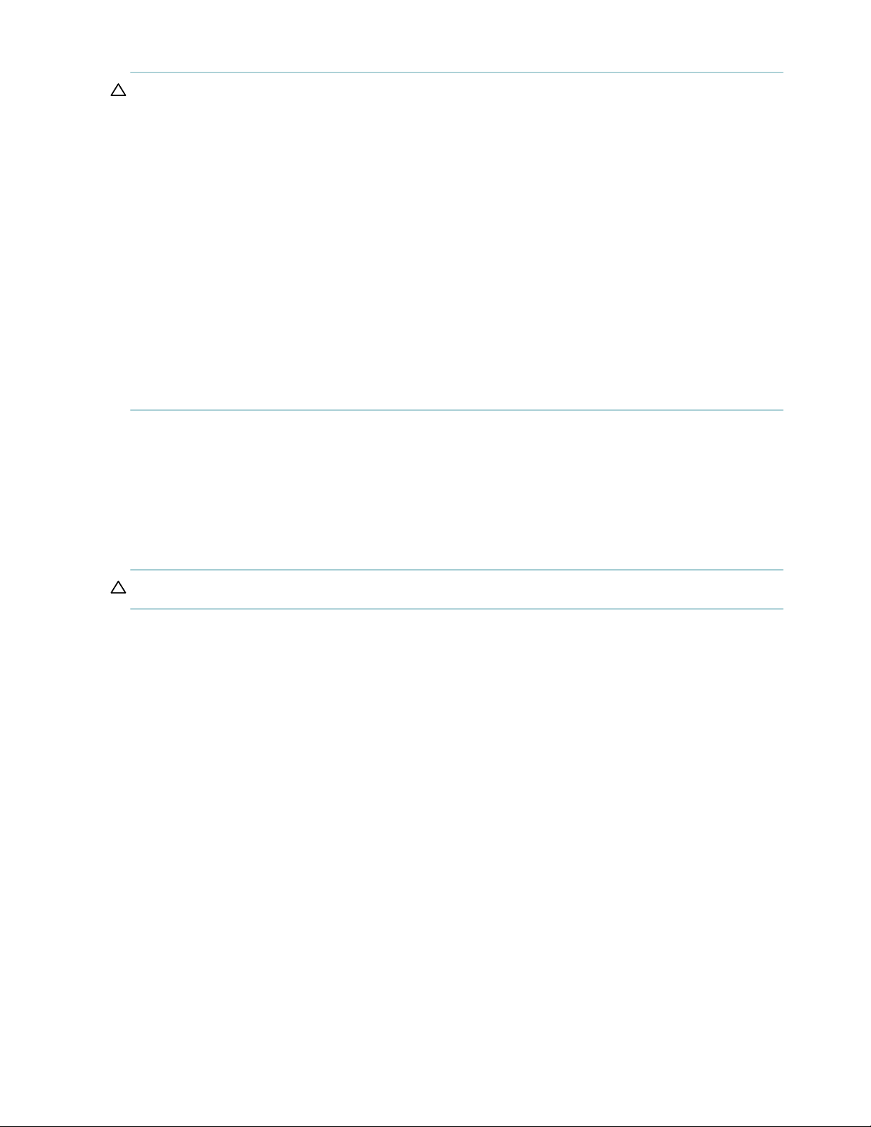
The Exos E 4U106 storage system fits within four rack space units. See Figure 1 and Figure 2. It holds up to 106
low profile (1-inch high) 3.5"
Alternatively, each drive slot can hold a low profile (5/8-inch high) 2.5" form factor drive with an adapter within
the large form factor carrier.
Each individual drive is hot pluggable and replaceable on site. Drive modules must be installed during system setup
after the enclosure is mounted on rails in the rack.
NOTE: Throughout this guide—and the management interface documents used with this guide—I/O module
(IOM) is a general term denoting an IOM (expansion canister).
The enclosure configurations—including chassis and FRUs—are described on the following pages. Refer to
“Enclosure Configuration” (page 17) for details about various enclosure options.
form factor drive modules vertically in 4U of rack space (hence, the term '4U106').
Figure 1 4U106 enclosure system – dimetric front orientation
Enclosure configuration 15
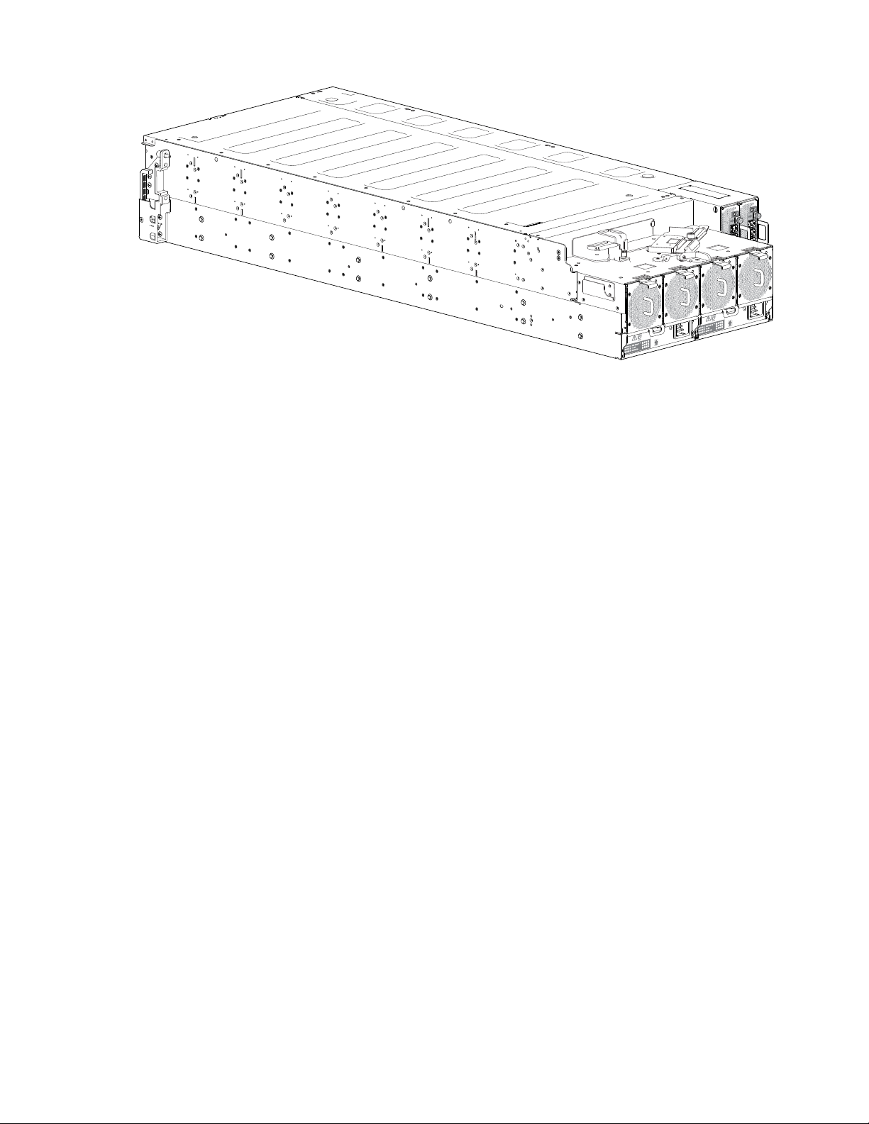
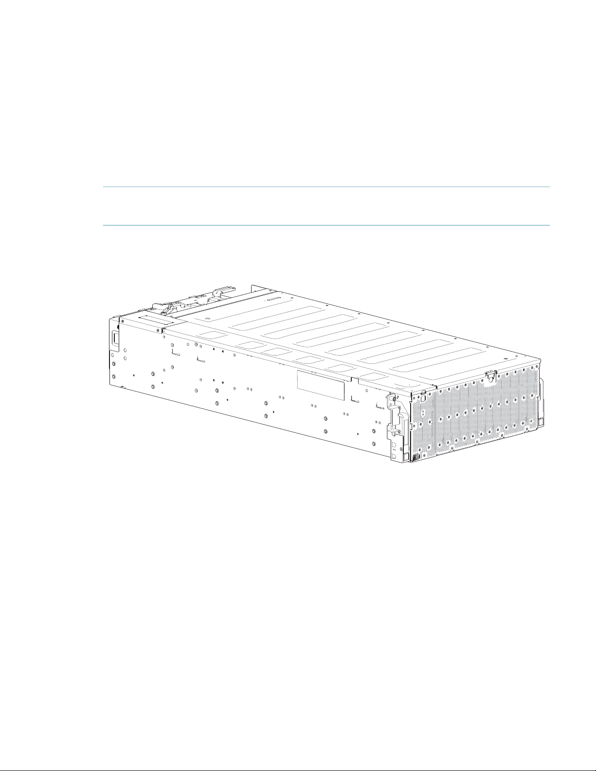
Figure 2 4U106 enclosure system – dimetric rear orientation
16 System overview

Enclosure Configuration
The 4U106 chassis is configured as an expansion enclosure, as shown in Table 2. The enclosure supports 106
qualified drive modules installed via the top panel.
• Hot-swappable (HS) expanders support 96 disc drives attached to four 24 HDD baseplanes (12 drives x 8
rows).
The 24 HDD baseplane continues to operate while the high-availability card is replaced when the enclosure:
Uses SAS drives
Does not use split-chassis shared-nothing firmware
Has a host connected to both IOMs
• The 10 HDD baseplane PCBA supports 10 drives (2 drives x 5 rows).
Table 2 4U106 enclosure configuration
Product Description of configuration PSUs
4U106 12Gb/s direct dock Large Form
Factor (LFF)
Enclosure location of FRU
Rear Rear Rear Top Top Top
variant
1-Redundant PSUs must be compatible modules of the same type (both AC).
2-For adequate cooling, four rear-panel system fans are required, and two IOM fans provide cooling for the IOMs (accessed via the top panel).
3-The IOM is used to connect the 4U106 to a host, or to connect to a host and additional storage enclosures.
4-LFF drives are supported using the 3.5" tool-less carrier; SFF drives are supported using the 2.5" tool-less carriers.
5-Hot-swappable expanders support 24 drive slots per drive row (8 rows total).
Enclosure core product
The design concept is based on an enclosure subsystem together with a set of plug-in Customer Replaceable Units
(FRUs). A typical enclosure System includes the following:
• An enclosure chassis equipped with several PCBAs, including a midplane, sideplane, and baseplane PCBAs,
and a cluster of enclosure status LED indicators located at the lower left area of the enclosure front panel
• Two PSU modules rated at 2,000W 200–240VAC
• Four rear fan modules for enclosure cooling
• One or two IOMs with four mini-SAS HD (SFF-8644) ports, a single serial port, and dual RJ-45 Ethernet
management ports (the Ethernet ports are not enabled). A single IOM must have IOM blank installed.
• Two fan controller modules for IOM cooling
• Up to 106 Disc Drive in Carriers (DDICs). 3.5” Large form factor (LFF) & 2.5” small form factor carrier are
available
• Eight removable hot-swappable expander cards, two per 24 HDD baseplane
• A rail kit for rack mounting.
• A cable management arm (CMA) for managing cables, and enabling in-rack servicing of the enclosure.
1
System fans2IOMs
3
IOM
2
fans
Drives
4
Expanders
HS
2 4 2 2 106 8
5
NOTE: About enclosure modules
• The drive modules are not installed when the enclosure ships. Do not insert drives into the enclosure until after
it has been secured in the rack. See also “Populating drive slots” (page 23).
• The following figures show component locations relative to the enclosure front, rear, and top panels.
• Refer to FRU Replacement Time Limit (Table 12) for maximum allowable time to replace FRUs.
Enclosure Configuration 17
Enclosure front panel
This enclosure front panel view intentionally omits the optional lift handles that attach to the enclosure sides and
that must be removed before pushing the enclosure mounted on the rails into the rack. It also does not show the
rails holding the enclosure when mounted in a rack because the rails are behind the pull handles.
Figure 3 4U106 enclosure system – front panel components
The enclosure front panel has seven system LEDs located in the lower left corner. See also Figure 3 (page 25). The
two enclosure pull handles used to slide the enclosure forward on its rails for in-rack servicing tasks are on the
right- and left-hand sides of the front panel.
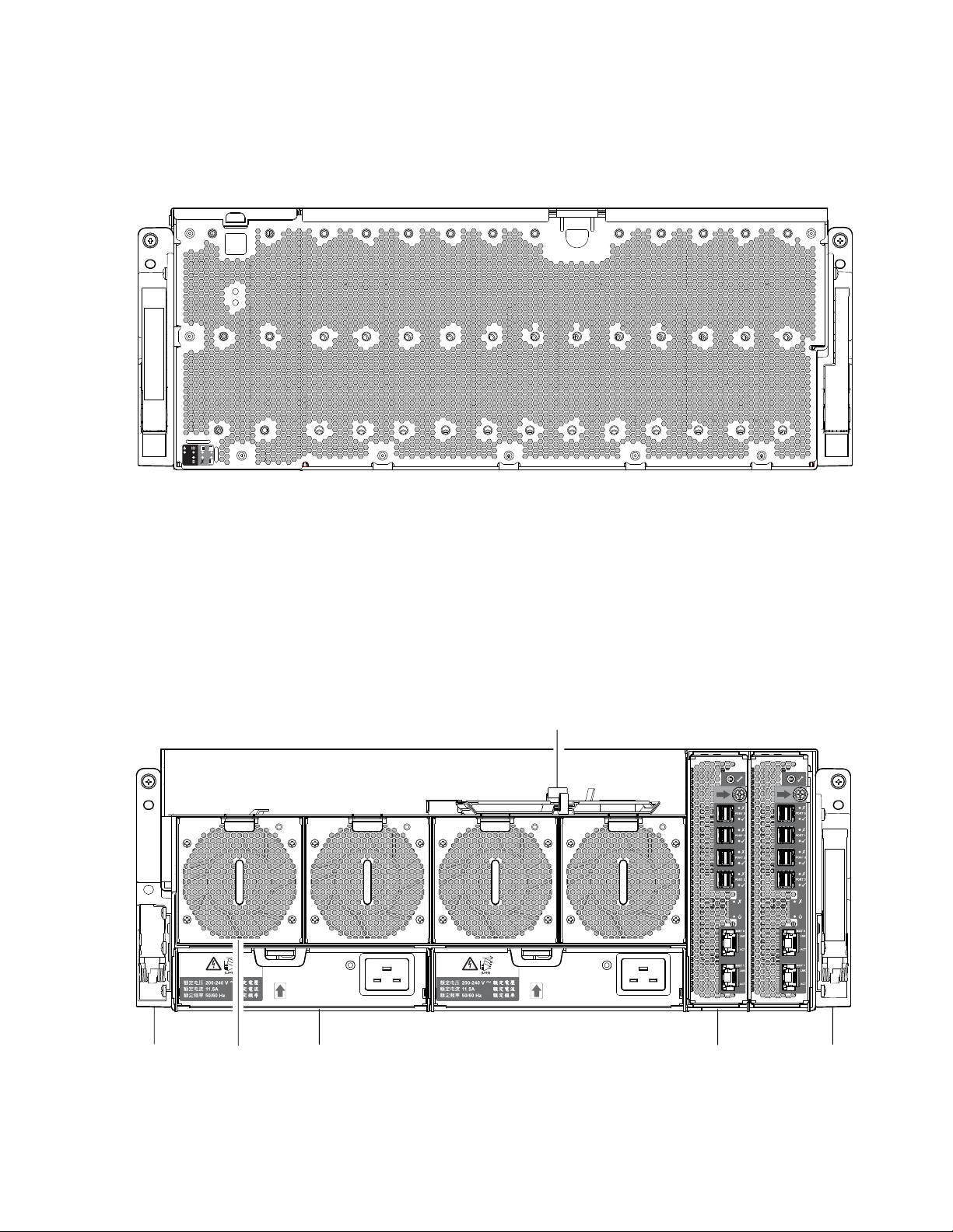
Enclosure rear panel
This enclosure rear panel view intentionally omits the optional lift handles that attach to the enclosure sides and
that must be removed before pushing the enclosure mounted on the rails into the rack. It also does not show the
rails holding the enclosure when mounted in a rack because the rails are behind the pull handles.
4
31 652
18 System overview
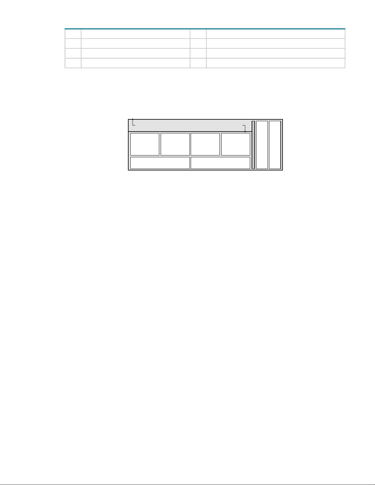
No. Description No. Description
System
Fan Module
Slot 0 Slot 1 Slot 2
Slot 3
PSU
Module Slot 0
PSU
Module Slot 1
Controller Slot 0
Controller Slot 1
System
Fan Module
System
Fan Module
System
Fan Module
Cable management recess and cable shelf
1 Right ear assembly (as viewed from back) 4 Cable shelf and CMA bracket for coiled cables
2 System fan module (quantity–4) 5 IOM (quantity–2)
3 Power supply unit (quantity–2) 6 Left ear assembly (as viewed from back)
Figure 4 4U106 enclosure system – rear panel components
See Figure 5 (page 19) for a conceptual diagram showing the numbering for each module bay that can be accessed
from the rear panel.
Rear panel components
Figure 5 4U106 enclosure – rear panel module slot index diagram
M
O
I
M
O
I
Enclosure core product 19
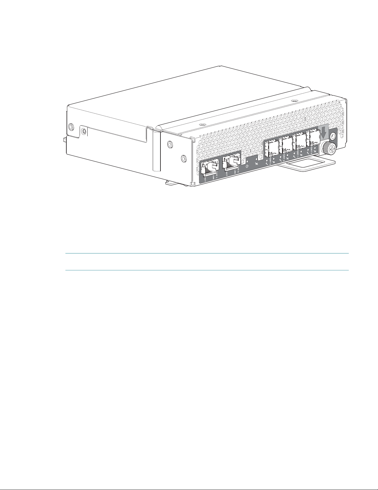
Expansion module
Figure 6 shows the IOM used in either IOM slot located on the enclosure rear panel. The module is shown resting
vertically in the install position.
Serial Port
Latch/lock
s
t
r
o
p
S
A
S
Figure 6 IOM detail
Ethernet Port
Ethernet Port
20 System overview
Power supply unit (PSU)
Figure 7 shows the PSU used in a 4U106 enclosure. The example shows a PSU oriented for use in either PSU slot
located on the enclosure rear panel.
Latch handle
Figure 7 Power supply unit (PSU) module detail
PSU status
AC power connect
System fan module
Figure 8 shows a system fan used in a 4U106 enclosure. The example shows a system fan module oriented for use
in any of the system fan slots located on the enclosure rear panel.
Latch/release tab
System fan status
Module handle
Figure 8 System fan module detail
Enclosure top panel
The enclosure top panel has two covers that can be removed for access to the internal components. The illustration
shows three parts of the top panel labeled as A, B, and C. See Figure 9 for more details.
• A: The removable main bay cover that provides access to the hot-swap expanders and 96 drive slots.
• B: The removable controller bay cover that provides access to 10 drive slots and the two internal fan modules.
• C: A fixed part of the enclosure chassis that cannot be removed.
Enclosure core product 21
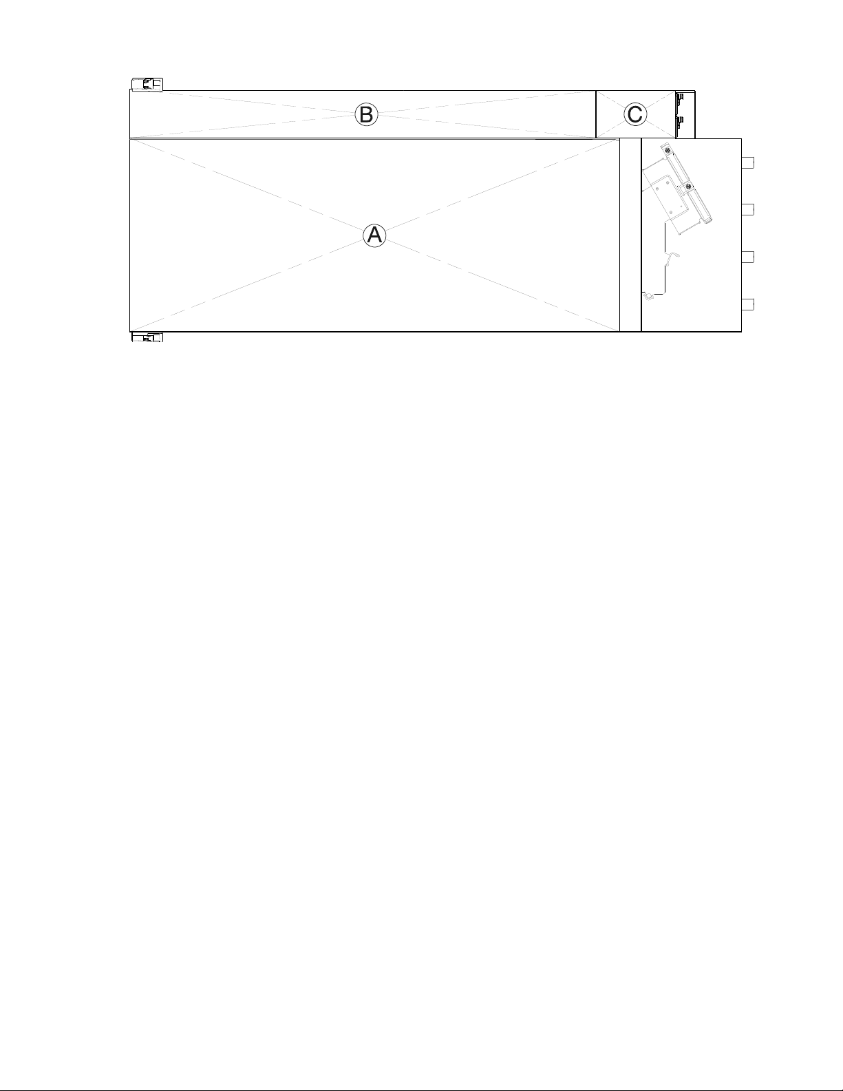
Figure 9 4U106 enclosure – top panel with covers installed
Figure 9 shows a top view of the enclosure with simplified covers. The illustration is oriented such that the front of
the enclosure is on left, and the rear of the enclosure is on the right. The rail kit and most of the cable management
arm geometry are omitted for clarity.
22 System overview
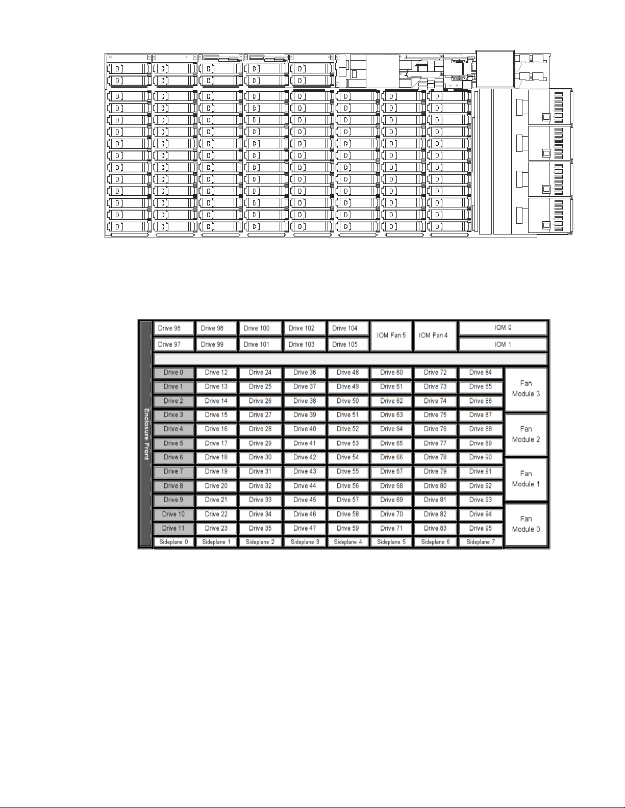
Figure 10 4U106 enclosure – top panel with covers not shown
Figure 11 provides a conceptual diagram of module slot-index numbering as viewed from the top of a 4U106
enclosure with all covers removed. To view the arrangement of PSU module slots—beneath the system fan
slots—see Figure 5 (page 19).
Figure 11 4U106 enclosure – top panel module slot index diagram
The 4U106 is designed for use with a full load of drives; however, it may also be partially populated. Gray-colored
drive slots above indicate minimum drive module placement for power and cooling reasons. These slots should be
populated in all cases.
Populating drive slots
The Exos E 4U106 does not ship with pre-installed drive modules. When installing drive modules, be mindful of
the slot numbering shown in Figure 11. The following rules apply when populating the 4U106 with drives
possessing 12 watts maximum drive operating power per slot.
• Populate the minimum drive slot arrangement indicated by gray-colored drive slots in Figure 11.
Enclosure core product 23

• Populate the remaining drive slots from enclosure from front to back – filling an entire lateral row (e.g., drives
0-11) - before populating the next row (e.g., drives 12-23, drives 24-34), and so on.
NOTE: A row can be skipped during loading, except the first row (Drive slot 0 to Drive slot 11). However, once
you start to fill a row ensure that you fill it completely.
• When rack-mounting a 4U106 enclosure, install the drives after the enclosure is installed in the rack.
• Populate drive slots 96–105 at any time during the sequence, as they are cooled separately within the enclosure.
Enclosure chassis
The 4U106 chassis consists of a sheet metal enclosure with integrated PCBAs. The enclosure is divided into a main
bay and a controller bay. Each bay has a removable cover to provide access to plug-in modules known as
field-replaceable units (FRUs). The metal surfaces are free from non-conductive coatings and paint
• The chassis has a 1.2 m rack mounting that enables it to be installed onto standard 1.2 m racks, and uses four
EIA units of rack space (7") for a 4U enclosure. Optional lift handles on the chassis side walls facilitate hoisting
and installation. See also Figure 24 (page 42).
• The cable management arm (CMA) routes cables from the controller channel and external connections and
secures them for in-rack servicing of the installed enclosure.
• The drive channel bus-bar distributes power from the power midplane to 24 HDD baseplanes.
• The four 24 HDD baseplane PCBAs support 96 drive connections in the drive channel.
• The 10 HDD baseplane PCBs supports 10 drive connections in the controller channel.
• The enclosure top panel provides access to 106 low profile 3.5" LFF or 2.5" SFF (with adapter) drives, held vertically.
Out of these 106 drives, 96 drives are present below cover A (main bay cover), and 10 drives (and two controller
channel fans) are present below the cover B (controller bay). See Figure 9 for more details. Each drive slot holds a
plug-in drive carrier module. The top panel also provides access to the HS expander and controller fan FRUs.
• Each 24 HDD base plane has a pair of hot-swappable expander cards (eight individual hot-swappable expander
cards). Each expander card plugs into a riser card that in turn connects to a baseplane.
• Within the controller bay, fans provide additional cooling for IOMs.
• In the rear, the chassis holds two PSUs, four system fans, two CFF-compliant IOMs and a cable management
arm to manage data & power cables.
• The main bay cover A, provides access to 96 low profile 3.5" LFF or 2.5" SFF with adapter drives, held
vertically. It also provides access to eight High Speed expander FRUs.
• The controller bay cover (cover B) provides access to 10 low profile 3.5" LFF or 2.5" SFF with adapter drives,
held vertically. It also provides access to two controller fan FRUs.
IMPORTANT: If the Exos E 4U106 enclosure is configured with a single IOM, it must be installed in IOM0 (as shown
in Figure 11). An IOM blank must be installed in the adjacent slot to ensure sufficient air flow through the enclosure
during operation.
24 System overview
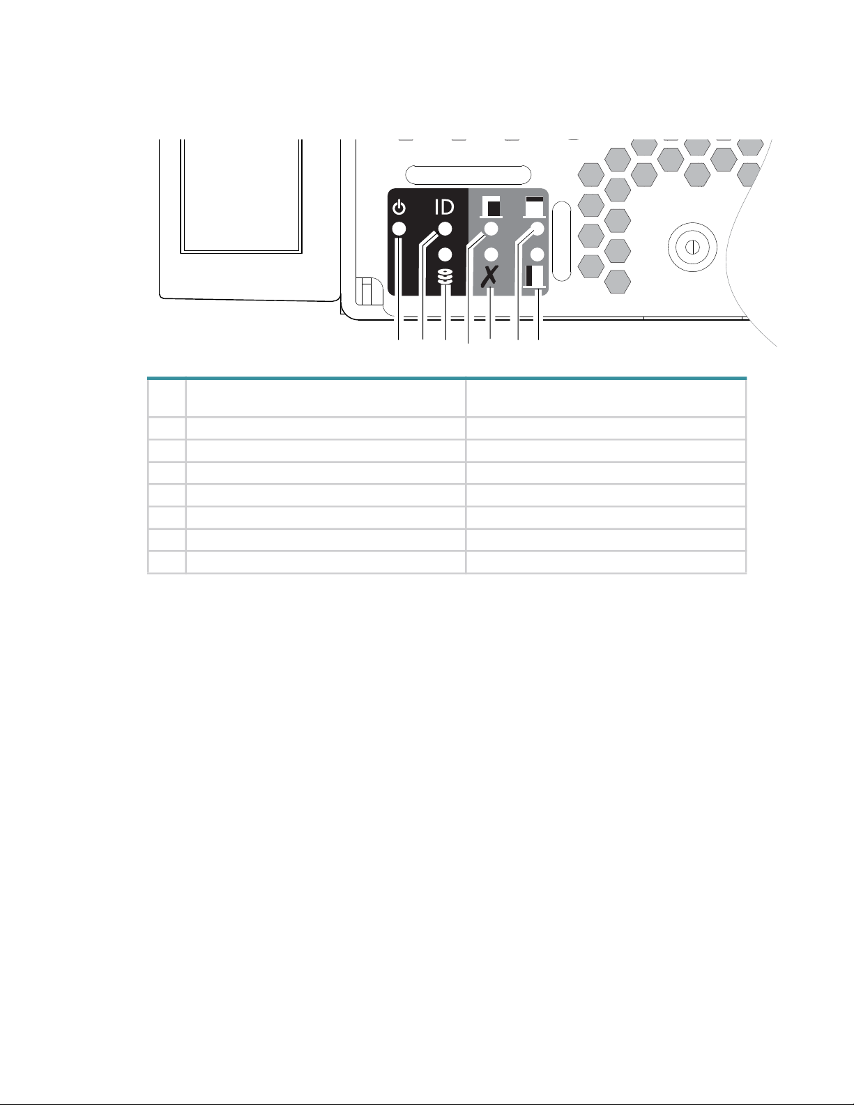
Overview of front panel LEDs
The enclosure front panel displays several LEDs. The front panel displays the functions shown in the illustration
below and listed in the table. See also Figure 3 (page 18).
Front panel – lower left corner (partial view)
LED Front panel functions (lower left corner of
panel)
1 System Power (green) Not reported
2 System ID (blue) Unit Identifier LED
3 Host Connectivity (green) Port Link Status Ops LED
4 Fault - Main Bay (amber) Module Fault LED
5 Fault - Application (amber) Logic Fault LED
6 Fault - Rear Module (amber) Module Fault Rear LED
7 Fault - Controller Bay (amber) Module Fault Side LED
Table 3 LEDs: 4U106 enclosure front panel
Front Panel LED Descriptions
• LED 1 System Power
This LED illuminates green when the system power is applied. If this LED is
off
or there is a power failure in the system. Troubleshoot to identify the cause.
• LED 2 System ID
This LED illuminates blue when activated and is used to identify the storage system among the other systems
installed in the rack. This LED is normally
by the application.
• LED 3 Host Connectivity
This LED illuminates green when a host port is linked up with either IOM.
• LED 4 Fault - Main Bay
This LED illuminates amber when experiencing a system hardware fault. The hardware fault can be initiated by
GEM for a component or FRU that is accessible through the main bay cover. This LED is normally
the chassis forward from its installed position within the rack, remove the main bay cover and look for amber
colored LED on any disc drives or HS expander modules. Replace the faulty component. If no LED is
illuminated in the Main Bay then contact Seagate support.
• LED 5 Fault - Application
This LED illuminates amber when experiencing a system fault that is initiated by the Application (Host). This
LED is normally
off
.
1 3 5
2
off
4
and illuminates only during the identification process initiated
6
7
LEDs as displayed in the output of the GEM
CLI command '
report_faults
off
, either the system is powered
'.
off
. Pull
Overview of front panel LEDs 25

• LED 6 Fault - Rear Module
This LED illuminates amber when experiencing a system hardware fault with an FRU accessible through the
rear of the enclosure (IOMs, PSUs, System Fans). This LED is normally
Rear Module then contact Seagate support.
• LED 7 Fault - Controller Bay
This LED illuminates amber when experiencing a system hardware fault initiated by GEM, for an FRU that is
accessible through the controller bay cover. This LED is normally
installed position within the rack, remove the controller bay cover and look for amber colored LED on disc
drives or controller fans. Replace the faulty component. If no LED is illuminated in the Main Bay then contact
Seagate support.
Overview of rear panel LEDs
Power supply unit
AC-DC power is provided by up to two auto-ranging power supply modules (PSUs). Cooling is provided by four
separate cooling fans and two controller module fans. The IOM provides power and LED control. Also see
“System airflow” (page 28) for optimal cooling within the enclosure(s).
off
. If no LED is illuminated in the
off
. Pull the chassis forward from its
26 System overview
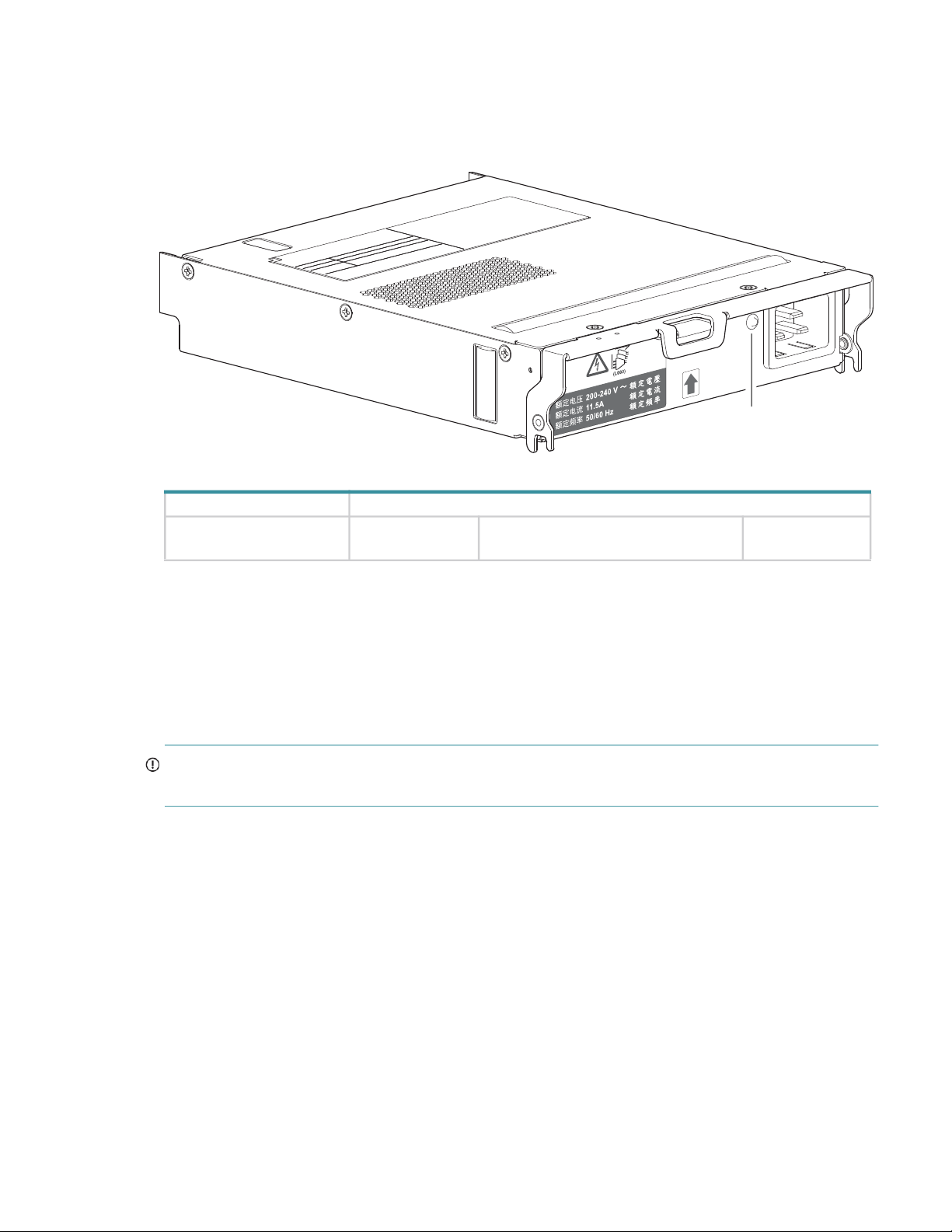
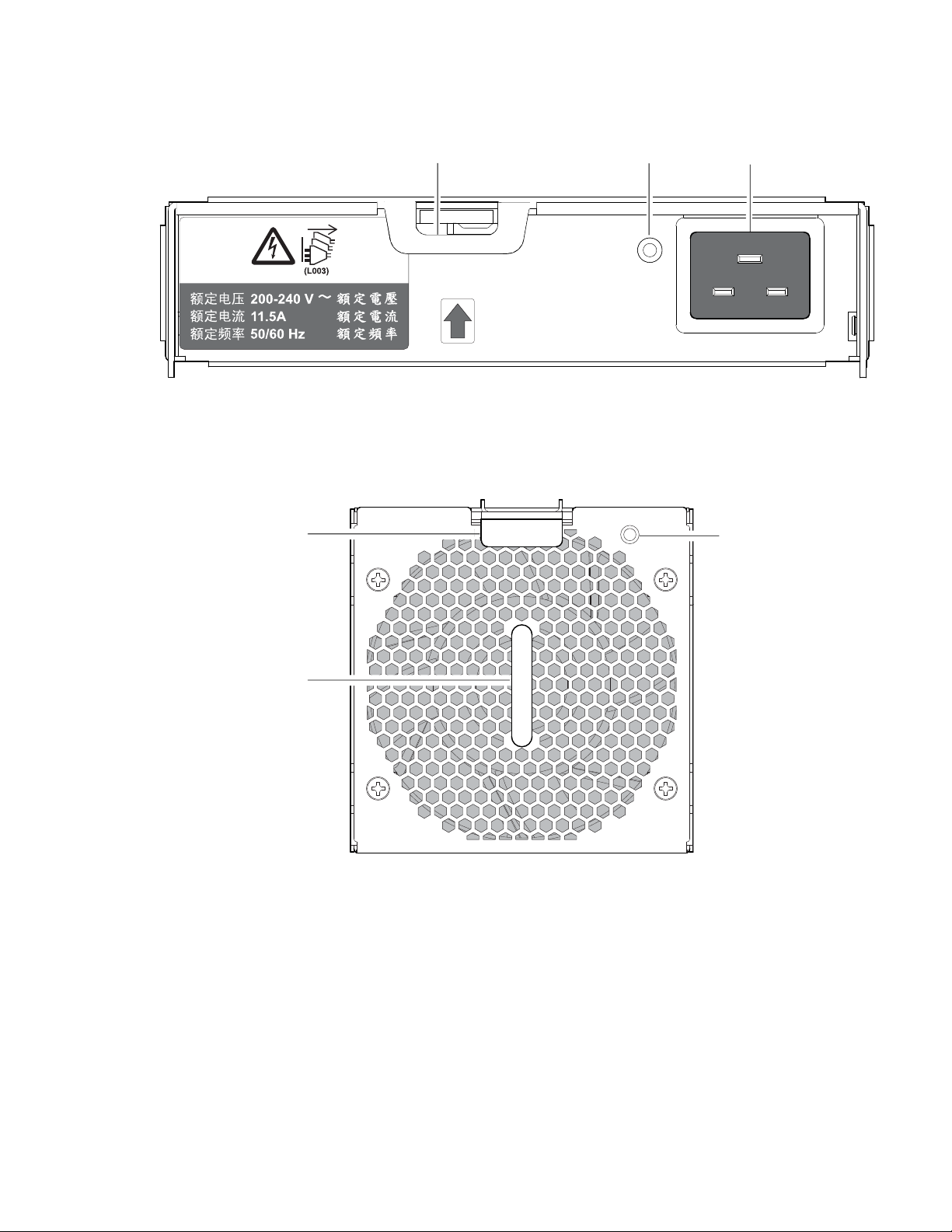
2,000W PSU
The 2,000W PSU voltage operating range is nominally 200V-240VAC, and the input frequency operating range is
50-60 Hz. The dimetric rear orientation in Figure 12 shows the PSU aligned for insertion into either PSU slot
located on the enclosure rear panel. Also remove the stabilizer bar before inserting or removing a PSU.
Module LED LED behavior states
PSU Status LED (bitonal): PSU OK (green) PSU fault/failure (amber/blinking
PSU Status LED
PSU oriented for use in rear panel slot
Power off (Off)
amber)
Figure 12 LEDs: 2,000W PSU – rear panel
Multiple power supply unit modules
The 4U storage system includes two hot-swappable PSUs that provide redundant power control for the system so
that if one module fails, the other maintains the power and enclosure operation is not affected while the faulty PSU
is being replaced. See FRU Replacement Time Limit (Table 12) for maximum allowable time to replace FRUs. See
section “Removing a PSU module” (page 75) for replacement instructions. Note the slide-rail crossbar needs to be
removed to get access to PSUs.
IMPORTANT: Operation of the enclosure with any modules missing will disrupt the airflow, and the drives will
not receive sufficient cooling. It is essential that all slots are fitted with PSUs prior to powering on the enclosure.
Overview of rear panel LEDs 27
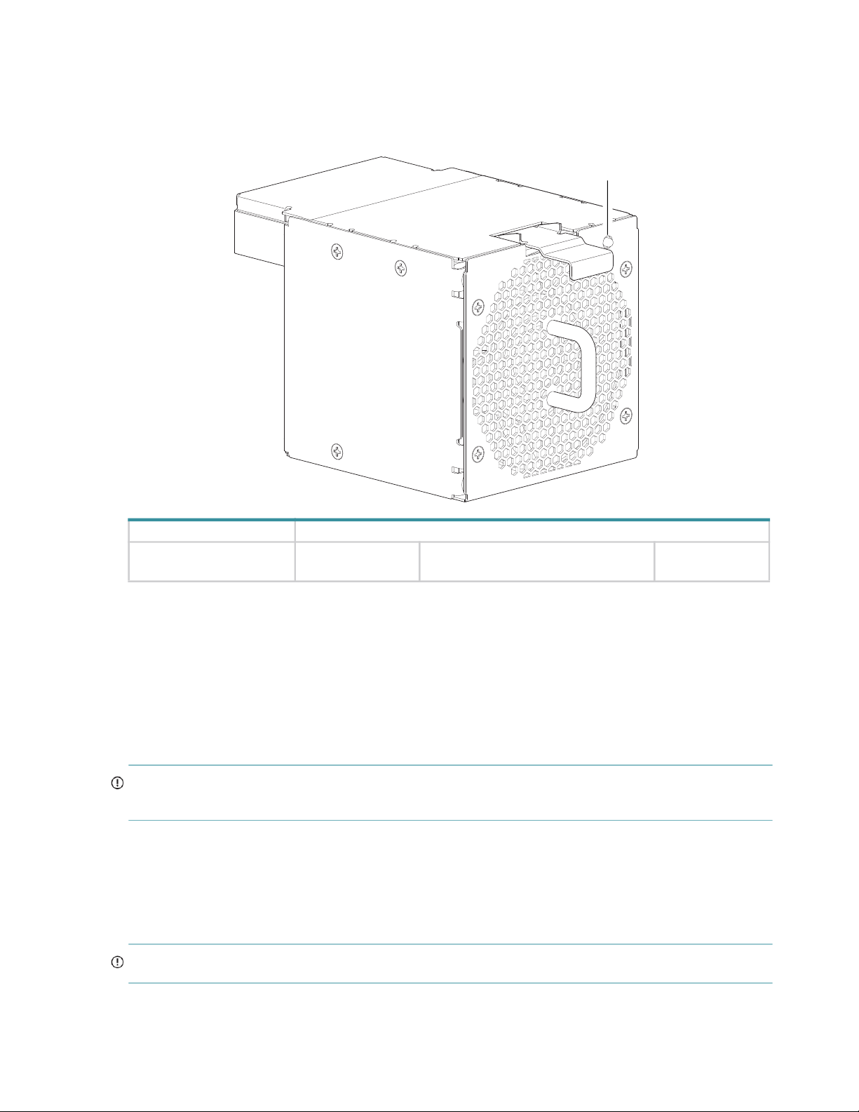
System fan module
Enclosure cooling is provided by four system fan modules used in combination with two controller channel fan
modules. The IOM provides fan and LED control. This section describes system fan modules. See also “Controller
channel fan module” (page 33).
System fan status LED
Module LED LED behavior states
System Fan Status LED: System Fan OK
Figure 13 LEDs: System fan module – rear panel
Multiple system fan modules
The 4U106 enclosure includes four system fan FRUs which provide redundant cooling for the system, so that if one
module fails, the others maintain airflow circulation, and enclosure operation is not affected while you replace the
faulty module. Within this FRU module, if one of the two internal rotors fails, then a fault occurs, indicating
module failure. A dual rotor failure is reported as a dual-fault. Refer to FRU Replacement Time Limit (Table 12)
for maximum allowable time to replace FRUs. See section “Replacing a system fan module” (page 77) and
“Replacing a controller fan module” (page 79) for replacement instructions.
IMPORTANT: Operation of the enclosure with any modules missing disrupts the airflow, and the drives do not
receive sufficient cooling. It is essential that all slots are fitted with system fans prior to powering on the enclosure.
System airflow
The system must be operated with low pressure rear exhaust installation. Back pressure created by rack doors and
obstacles is not to exceed 5 pascals (0.5mm water gauge). The cooling system provides sufficient capacity to
ensure that maximum temperatures are not exceeded.
System fan oriented for use in rear panel slot
Fan fault/ID (amber/blinking amber) Power off (Off)
(Off)
IMPORTANT: The environment in which the enclosure operates must be dust-free to ensure adequate airflow.
28 System overview
IOM module
This section describes the IOM used in Exos E 4U106 12Gb/s storage enclosures.
Figure 14 IOM
Each IOM maintains Vital Product Data (VPD) in EEPROM device and are interconnected by I2C buses on the
midplane creating an interlink between the two modules. An enclosure system fault occurs when incompatible
configurations are detected.
Refer to FRU Replacement Time Limit (Table 12) for maximum allowable time to replace FRUs. See section
“Replacing an IOM” (page 85) for replacement instructions.
NOTE: For a description of IOM LEDs, see “12Gb/s IOM LEDs” (page 30).
Overview of rear panel LEDs 29
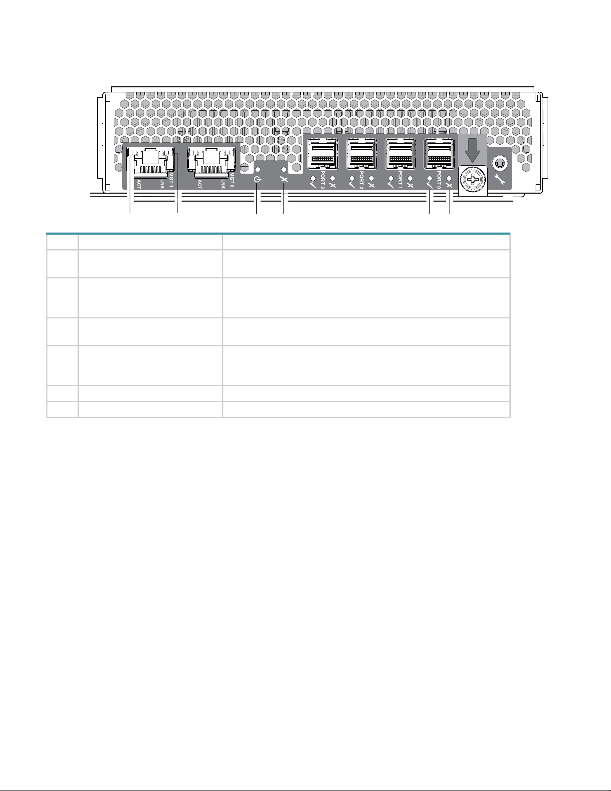
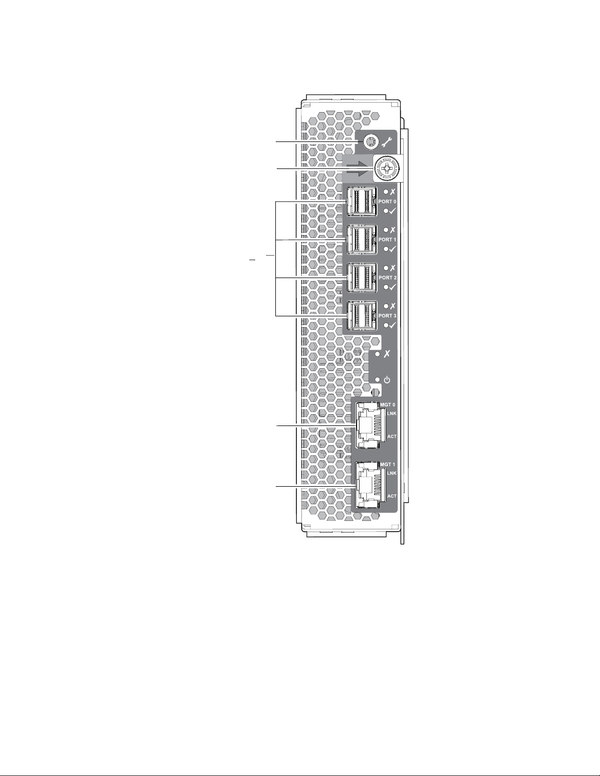
12Gb/s IOM LEDs
Insert IOM into a slot as shown in Figure 6 (page 20).
56 4 3
LED Description Definition
1 12Gb SAS Fault
1
Off — No fault detected.
Amber— A fault has been detected on the port.
2 12Gb SAS Link Status and
Activity
1
Off — No link detected.
Green — The port is connected and the link is up.
Blinking green — The link has I/O activity.
3 Fault Off — The IOM is operating normally.
Amber — A fault has been detected or a service action is required.
4 Power OK Green — The IOM is operating normally.
Blinking green — System is booting.
Off — The IOM is powered off.
5 Ethernet Port Link Speed
6 Ethernet Port Link/Active Status
1–This LED description applies to all 12Gb SAS ports (Port 0 through 3)
2–This LED description applies to both management ports (Port 0 and Port 1)
2
Not Applicable (Port Disabled).
2
Not Applicable (Port Disabled).
Figure 15 LEDs: IOM – rear panel
Overview of top panel LEDs
To view LEDs of components that are accessible from the Main Bay & Controller Bay covers, you must first
remove the lid for the compartment in which the component is installed. The enclosure top panel is shown in
Figure 9 (page 22).
2 1
Drive carrier module
The drive carrier module comprises a hard drive held by a carrier.
• Each 4U106 drive slot can hold a single low profile (1.0-inch) 3.5-inch form factor drive in its carrier.
• Each 4U106 drive slot can hold a single low profile (5/8-inch) 2.5-inch form factor drive with adapter in its
carrier.
• The drive modules are inserted into vertically aligned slots that are accessible from the top of the enclosure.
While facing the front of the enclosure, properly orient the drive module for insertion into the slot:
Hold the module so that the front is facing you (latch tab on left, and drive PCB facing up).
Revolve the module -90º about the horizontal axis (latch is facing up, module is standing on end)
Revolve the module 90º about the vertical axis (latch is facing up, drive PCB is facing left).
30 System overview
 Loading...