


DiamondMax™ 1750 UDMA
8
7000D8, 86480D8, 85250D6
84320D5, 83500D4, 83240D4
82560D3, 81750D2
Part #1381/A
All material contained herein Copyright © 1997 Maxtor Corporation.
CrystalMax™, CrystalMax™ 1080, DiamondMax™, DiamondMax™
1750 and MaxFax™ are trademarks of Maxtor Corporation. No Quibble
Service is a registered trademark of Maxtor Corporation. Other brands or
products are trademarks or registered trademarks of their respective holders.
Contents and specifications subject to change without notice. All rights
reserved. Printed in the U.S.A. 6/97
Corporate Headquarters
510 Cottonwood Drive
Milpitas, California 95035
Tel: 408-432-1700
Fax: 408-432-4510
Research and Development
Engineering Center
2190 Miller Drive
Longmont, Colorado 80501
Tel: 303-651-6000
Fax: 303-678-2165
®

Revisions Manual No. 1381
REV EC NO. SECTION DESCRIPTION DATE
A 78533 All Initial release 06/10/97

Before You Begin
Thank you for your interest in the Maxtor DiamondMax™ 1750 AT hard disk drives. This manual provides technical
information for OEM engineers and systems integrators regarding the installation and use of the 87000D8, 86480D8,
85250D6, 84320D5, 83500D4, 83240D4, 82560D3 and 81750D2.
Drive repair should be performed only at an authorized repair center. For repair information, contact the
Maxtor Customer Service Center at 800-2MAXTOR or 408-432-1700.
Before unpacking the hard drive, please review Sections 1 through 4.
CAUTION
Maxtor DiamondMax 1750 hard drives are precision products. Failure to
follow these precautions and guidelines outlined here may lead to
product failure, damage and invalidation of all warranties.
1
2
3
4
5
BEFORE unpacking or handling a drive, take all proper electro-static discharge (ESD)
precautions, including personnel and equipment grounding. Stand-alone drives are
sensitive to ESD damage.
BEFORE removing drives from their packing material, allow them to reach room
temperature.
During handling, NEVER drop, jar, or bump a drive.
Once a drive is removed from the Maxtor shipping container, IMMEDIATELY secure the
drive through its mounting holes within a chassis. Otherwise, store the drive on a padded,
grounded, antistatic surface.
NEVER switch DC power onto the drive by plugging an electrically live DC source cable
into the drive's connector. NEVER connect a live bus to the drive's interface connector.
Please do not remove or cover up Maxtor factory-installed drive labels.
They contain information required should the drive ever need repair.

DIAMONDMAX 1750 PRODUCT MANUAL
Contents
Section 1 — Introduction
Maxtor Corporation 1 - 1
Products 1 - 1
Support 1 - 1
Manual Organization 1 - 1
Abbreviations 1 - 1
Conventions 1 - 2
Key Words 1 - 2
Numbering 1 - 2
Signal Conventions 1 - 2
Section 2 — Product Description
The 87000D8, 86480D8, 85250D6, 84320D5, 83500D4, 2 - 1
83240D4, 82560D3 and 81750D2
Product Features 2 - 2
Functional/Interface 2 - 2
Zone Density Recording 2 - 2
Read/Write Multiple Mode 2 - 2
UltraDMA - Mode 2 2 - 2
Multi-word DMA (EISA Type B) - Mode 2 2 - 2
Sector Address Translation 2 - 2
Logical Block Addressing 2 - 3
Defect Management Zone 2 - 3
On-the-Fly Hardware Error Correction Code (ECC) 2 - 3
Software ECC Correction 2 - 3
Automatic Head Park and Lock Operation 2 - 3
Cache Management 2 - 4
Buffer Segmentation 2 - 4
Read-Ahead Mode 2 - 4
Automatic Write Reallocation (AWR) 2 - 4
Write Cache Stacking 2 - 4
Major HDA Components 2 - 5
Drive Mechanism 2 - 5
Rotary Actuator 2 - 5
Read/Write Electronics 2 - 5
Read/Write Heads and Media 2 - 5
Air Filtration System 2 - 5
Microprocessor 2 - 5
Subsystem Configuration 2 - 6
Dual Drive Support 2 - 6
Cable Select Option 2 - 6
Jumper Location/Configuration 2 - 6
4092 Cylinder Limitation 2 - 6
Section 3 — Product Specifications
Configuration 3 - 1
Performance 3 - 1
Physical Dimensions 3 - 2
Power Requirements 3 - 3
Power Mode Definitions 3 - 3
Environmental 3 - 3
Shock and Vibration 3 - 4
Reliability and Maintenance 3 - 4
iv

DIAMONDMAX 1750 PRODUCT MANUAL
Data Reliability 3 - 4
Acoustic Noise 3 - 4
EPA Energy Star Compliance 3 - 4
EMC/EMI 3 - 5
Standard Test Methods 3 - 5
Safety Regulatory Compliance 3 - 5
Section 4 — Handling and Installation
Pre-formatted Drive 4 - 1
Important Notice 4 - 1
Hard Drive Handling Precautions 4 - 1
Electro-Static Discharge (ESD) 4 - 1
Unpacking and Inspection 4 - 2
Repacking 4 - 3
Physical Installation 4 - 3
Drive Jumper Settings 4 - 4
Mounting Drive in System 4 - 4
Attaching IDE Interface and Power Cables 4 - 6
Attaching System Cables 4 - 7
System Setup 4 - 8
Hard Drive Preparation 4 - 10
Section 5 — AT Interface Description
Interface Connector 5 - 1
Pin Description Summary 5 - 1
Pin Description Table 5 - 2
PIO Timing 5 - 3
DMA Timing 5 - 4
Ultra DMA Timing Parameters 5 - 5
Section 6 — Host Software Interface
Task File Registers 6 - 1
Data Register 6 - 1
Error Register 6 - 1
Features Register 6 - 1
Sector Count Register 6 - 2
Sector Number Register 6 - 2
Cylinder Number Registers 6 - 2
Device/Head Register 6 - 2
Status Register 6 - 2
Command Register 6 - 3
Read Commands 6 - 3
Write Commands 6 - 3
Mode Set/Check Commands 6 - 3
Power Mode Commands 6 - 3
Initialization Commands 6 - 3
Seek, Format, and Diagnostic Commands 6 - 3
S.M.A.R.T. Commands 6 - 3
Summary 6 - 4
Control Diagnostic Registers 6 - 5
Alternate Status Register 6 - 5
Device Control Register 6 - 5
Digital Input Register 6 - 5
Reset and Interrupt Handling 6 - 6
v

DIAMONDMAX 1750 PRODUCT MANUAL
Section 7 — Interface Commands
Command Summary 7 - 1
Read Commands 7 - 2
Read Sector(s) 7 - 2
Read Verify Sector(s) 7 - 2
Read Sector Buffer 7 - 2
Read DMA 7 - 3
Read Multiple 7 - 3
Set Multiple 7 - 3
Write Commands 7 - 4
Write Sector(s) 7 - 4
Write Verify Sector(s) 7 - 4
Write Sector Buffer 7 - 4
Write DMA 7 - 5
Write Multiple 7 - 5
Ultra DMA 7 - 5
Set Feature Commands 7 - 5
Set Features Mode 7 - 5
Power Mode Commands 7 - 7
Standby Immediate 7 - 7
Idle Immediate 7 - 7
Standby 7 - 7
Idle 7 - 7
Check Power Mode 7 - 7
Set Sleep Mode 7 - 7
Default Power-on Condition 7 - 7
Initialization Commands 7 - 9
Identify Drive 7 - 9
Initialize Drive Parameters 7 - 12
Seek, Format, and Diagnostic Commands 7 - 13
S.M.A.R.T. Command Set 7 - 14
Section 8 — Service and Support
Service Policy 8 - 1
No Quibble Service 8 - 1
Support 8 - 1
Glossary
Glossary GL - 1
vi

DIAMONDMAX 1750 PRODUCT MANUAL
Figures
Figure Title Page
2 - 1 PCBA Jumper Locations and Configuration 2 - 6
3 - 1 Outline and Mounting Dimensions 3 - 2
4 - 1 Multi-pack Shipping Container 4 - 2
4 - 2 Single-pack Shipping Container (Option A) 4 - 3
4 - 3 Single-pack Shipping Container (Option B) 4 - 3
4 - 4 Master/Slave Jumper Detail 4 - 4
4 - 5 5.25-inch Mounting Brackets/Slider Rails 4 - 4
4 - 6 5.25-inch Installation 4 - 5
4 - 7 3.5-inch Installation 4 - 5
4 - 8 IDE Interface and Power Cabling Detail 4 - 6
4 - 9 System Interface Card Cabling 4 - 7
4 - 10 System Mother Board Cabling 4 - 7
4 - 11 J46 (4092 Cylinder Limitation) Detail 4 - 9
5 - 1 Data Connector 5 - 1
5 - 2 PIO Data Transfer to/from Device 5 - 3
5 - 3 Multi-word DMA Data Transfer 5 - 4
5 - 4 Initiating an Ultra DMA Data In Burst 5 - 5
5 - 5 Sustained Ultra DMA Data In Burst 5 - 6
5 - 6 Host Pausing an Ultra DMA Data In Burst 5 - 6
5 - 7 Device Terminating an Ultra DMA Data In Burst 5 - 7
5 - 8 Host Terminating an Ultra DMA Data In Burst 5 - 7
5 - 9 Initiating an Ultra DMA Data Out Burst 5 - 8
5 - 10 Sustained Ultra DMA Data Out Burst 5 - 8
5 - 11 Device Pausing an Ultra DMA Data Out Burst 5 - 9
5 - 12 Host Terminating an Ultra DMA Data Out Burst 5 - 9
5 - 13 Device Terminating an Ultra DMA Data Out Burst 5 - 10
vii
DIAMONDMAX 1750 – INTRODUCTION
SECTION 1
Introduction
Maxtor Corporation
Maxtor Corporation has been providing high-quality computer storage products since 1982. Along the way, we’ve seen many
changes in data storage needs. Not long ago, only a handful of specific users needed more than a couple hundred megabytes of
storage. Today, downloading from the Internet and CD-ROMs, multimedia, networking and advanced office applications are
driving storage needs even higher. Even home PC applications need capacities measured in gigabytes, not megabytes.
Products
Maxtor’s products meet those demanding storage capacity requirements with room to spare. They feature proven
compatibility and reliability. While DiamondMax™ 1750 UDMA is the latest addition to our family of high
performance desktop hard drives, the CrystalMax™ and CrystalMax™ 1080 series hard drives deliver industry-leading
capacity and value for most PC applications.
Support
No matter which capacity, all Maxtor hard drives are supported by our commitment to total customer satisfaction and our
No Quibble
you in touch with either technical support or customer service. We’ll provide you the information you need quickly,
accurately and in the form you prefer – a fax, a downloaded file or a conversation with a representative.
®
Service guarantee. One call – or a visit to our home page on the Internet (http://www.maxtor.com) – puts
Manual Organization
This hard disk drive reference manual is organized in the following method:
❏ Section 1 – Introduction
❏ Section 2 – Description
❏ Section 3 – Specifications
❏ Section 4 – Installation
❏ Section 5 – AT Interface
❏ Section 6 – Host Software Interface
❏ Section 7 – Interface Commands
❏ Section 8 – Service and Support
❏ Appendix – Glossary
Abbreviations
ABBRV DESCRIPTION ABBRV DESCRI PTION
ATA AT attachment MB megabyte
bpi bits per inch Mbits/sec megabits per second
CHS cylinder - head - sector MB/sec megabytes per second
db decibels MHz megahertz
dBA decibels, A weighted ms millisecond
DMA direct memor y access MSB most si gnificant bit
ECC error correction code mV millivolts
fci flux changes per inch ns nanoseconds
G acceleration PIO programmed input/output
GB gigabyte RPM revolutions per minute
Hz hertz tpi tr acks per inch
KB kilobyte µsec microsecond
LBA logical block address V volts
LSB lea st significant bit W watts
mA mil liamperes
1 – 8

DIAMONDMAX 1750 – INTRODUCTION
Conventions
If there is a conflict between text and tables, the table shall be accepted as being correct.
Key Words
The names of abbreviations, commands, fields and acronyms used as signal names are in all uppercase type (e.g.,
IDENTIFY DRIVE). Fields containing only one bit are usually referred to as the “name” bit instead of the “name” field.
Names of drive registers begin with a capital letter (e.g., Cylinder High register).
Numbering
Numbers that are not followed by a lowercase “b” or “h” are decimal values. Numbers that are followed by a lowercase
“b” (e.g., 01b) are binary values. Numbers that are followed by a lowercase “h” (e.g., 3Ah) are hexadecimal values.
Signal Conventions
Signal names are shown in all uppercase type.
All signals are either high active or low active signals. A dash character (-) at the end of a signal name indicates that the
signal is low active. A low active signal is true when it is below ViL and is false when it is above ViH. A signal without a
dash at the end indicates that the signal is high active. A high active signal is true when it is above ViH and is false when it
is below ViL.
When a signal is asserted, it means the signal is driven by an active circuit to its true state.
When a signal is negated, it means the signal is driven by an active circuit to its false state.
When a signal is released, it means the signal is not actively driven to any state. Some signals have bias circuitry that pull the
signal to either a true or false state when no signal driver is actively asserting or negating the signal. These instances are
noted under the description of the signal.
1 – 9

PRODUCT DESCRIPTION
SECTION 2
Product Description
Maxtor DiamondMax™ 1750 AT disk drives are 1-inch high, 3.5-inch diameter random access storage devices which
incorporate an on-board UltraDMA/ATA controller. High capacity is achieved by a balanced combination of high areal
recording density and the latest data encoding and servo techniques.
Maxtor's latest advancements in electronic packaging and integration methods have lowered the drive's power consumption and
increased its reliability. Advanced magneto-resistive read/write heads, an state-of-the-art head/disk assembly using an integrated
motor/spindle design allow up to four disks in a 3.5-inch package.
Exceptionally high data transfer rates and sub 10 ms access times make these performance series disk drives especially well-suited
to high speed desktop and server applications.
DiamondMax 1750 Key Features
ANSI ATA-4 compliant PIO Mode 4 interface (Enhanced IDE)
Supports UltraDMA Mode 2 for 33 MB/sec data transfers
256 KB buffer with multi-adaptive cache manager
< 10 ms seek time
Zone density and I.D.-less recording
High reliability with
Outstanding shock resistance at 200 Gs
High durability with 50K constant start/stop cycles
Advanced multi-burst on-the-fly Error Correction Code (ECC)
Extended data integrity with ECC protected data and fault tolerant servo synchronization fields
Supports EPA Energy Star Standards (Green PC Friendly) with ATA powering savings commands
Auto park and lock actuator mechanism
Low power consumption
S.M.A.R.T. Capability
Note: Maxtor defines one megabyte as 106 or one million bytes and one gigabyte as 109 or one billion bytes.
>
500,000 hour MTBF
2 – 10
PRODUCT DESCRIPTION
Product Features
Functional / Interface
Maxtor DiamondMax™ 1750 hard drives contain all necessary mechanical and electronic parts to interpret control signals and
commands from an AT-compatible host computer. See Section 3, Product Specifications, for complete drive specifications.
Zone Density Recording
The disk capacity is increased with bit density management – common with Zone Density Recording. Each disk surface is
divided into 16 circumferential zones. All tracks within a given zone contain a constant number of data sectors. The
number of data sectors per track varies in different zones; the outermost zone contains the largest number of data sectors
and the innermost contains the fewest.
Read/Write Multiple Mode
This mode is implemented per ANSI ATA/ATAPI-4 specification. Read/Write Multiple allows the host to transfer a set
number of sectors without an interrupt request between them, reducing transfer process overhead and improving host
performance.
UltraDMA - Mode 2
Maxtor DiamondMax 1750 hard drives fully comply with the new UltraDMA protocol, which greatly improves overall
AT interface performance by significantly improving burst and sustained data throughput.
Multi-word DMA (EISA Type B) - Mode 2
Supports multi-word Direct Memory Access (DMA) EISA Type B mode transfers.
Sector Address Translation
All DiamondMax 1750 drives feature a universal translate mode. In an AT/EISA-class system, the drive may be
configured to any specified combination of cylinders, heads and sectors (within the range of the drive's formatted capacity).
DiamondMax 1750 drives power-up in a translate mode:
MODEL CYLIN DER S HEADS SECTORS CAPACITY
87000D8 14,475 15 63 7,000 MB
86480D8 13,392 15 63 6,480 MB
85250D6 10,856 15 63 5,250 MB
84320D5 8,928 15 63 4,320 MB
83500D4 7,237 15 63 3,500 MB
83240D4 6,696 15 63 3,240 MB
82560D3 5,292 15 63 2,560 MB
81750D2 3,618 15 63 1,750 MB
2 – 11

PRODUCT DESCRIPTION
Logical Block Addressing
The Logical Block Address (LBA) mode can only be utilized in systems that support this form of translation. The cylinder,
head and sector geometry of the drive, as presented to the host, differs from the actual physical geometry.
The host AT computer may access a drive of set parameters: number of cylinders, heads and sectors per track, plus
cylinder, head and sector addresses. However, the drive can’t use these host parameters directly because of zoned recording
techniques. The drive translates the host parameters to a set of logical internal addresses for data access. The host drive
geometry parameters are mapped into an LBA based on this formula:
L BA = (HSCA - 1) + HHDA x HSPT + HNHD x HSPT x HCYA (1 )
where HSCA = Host Sector Address, HHDA = Host Head Address, HCYA = Host Cylinder Address, HNHD = Host Number of Heads
= (HSCA - 1) + HSPT x (HHDA + HNHD x HCYA) (2)
HSPT = Host Sectors per Track
The LBA is checked for violating the drive capacity. If it does not, the LBA is converted to physical drive cylinder, head
and sector values. The physical address is then used to access the data stored on the disk and other drive related operations.
Defect Management Zone (DMZ)
Each drive model has a fixed number of spare sectors per drive, all of which are located at the end of the drive. Upon
detection of a bad sector that has been reassigned, the next sequential sector is used.
For example, if sector 3 is flagged, data that would have been stored there is “pushed down” and recorded in sector 4.
Sector 4 then effectively becomes sector 3, as sequential sectors are “pushed down” across the entire drive. The first spare
sector makes up for the loss of sector 3, and so maintains the sequential order of data. This push down method assures
maximum performance.
On-the-Fly Hardware Error Correction Code (ECC)
10 bits, single burst, guaranteed
Software ECC Correction
64 bits, single burst, guaranteed; 28 bits, double bursts, guaranteed
Automatic Park and Lock Operation
Immediately following power down, dynamic braking of the spinning disks delays momentarily allowing the read/write
heads to move to an inner mechanical stop. A small fixed magnet holds the rotary actuator in place as the disk spins down.
The rotary actuator is released only when power is again applied.
2 – 12

PRODUCT DESCRIPTION
Cache Management
Buffer Segmentation
The data buffer is organized into two segments: the data buffer and the micro controller scratch pad. The data buffer is
dynamically allocated for read and write data depending on the commands received. A variable number
of read and write buffers may exist at the same time.
Read-Ahead Mode
Normally, this mode is active. Following a read request, disk read-ahead begins on the first sector and continues
sequentially until the allocated buffer is full. If a read request is received during the read-ahead operation, the buffer is
examined to determine if the request is in the cache. If a cache hit occurs, read-ahead mode continues without
interruption and the host transfer begins immediately.
Automatic Write Reallocation (AWR)
This feature is part of the write cache and reduces the risk of data loss during deferred write operations. If a disk error
occurs during the disk write process, the disk task stops and the suspect sector is reallocated to a pool of alternate sectors
located at the end of the drive. Following reallocation, the disk write task continues until it is complete.
Write Cache Stacking
Normally, this mode is active. Write cache mode accepts the host write data into the buffer until the buffer is full or the
host transfer is complete. A command complete interrupt is generated at the end of the transfer.
A disk write task begins to store the host data to disk. Host write commands continue to be accepted and data transferred to
the buffer until either the write command stack is full or the data buffer is full. The drive may reorder write commands to
optimize drive throughput.
2 – 13

PRODUCT DESCRIPTION
Major HDA Components
Drive Mechanism
A brush-less DC direct drive motor rotates the spindle at 5,200 RPM (±0.1%). The dynamically balanced motor/spindle
assembly ensures minimal mechanical run-out to the disks. A dynamic brake provides a fast stop to the spindle motor upon
power removal. The speed tolerance includes motor performance and motor circuit tolerances.
Rotary Actuator
All DiamondMax™ 1750 drives employ a rotary voice coil actuator which consists of a moving coil, an actuator arm
assembly and stationary magnets. The actuator moves on a low-mass, low-friction center shaft. The low friction contributes
to fast access times and low power consumption.
Read/Write Electronics
An integrated circuit mounted within the sealed head disk assembly (near the read/write heads) provides up to eight head
selection (depending on the model), read pre-amplification and write drive circuitry.
Read/Write Heads and Media
Low mass, low force magneto-resistive read/write heads record data on 3.5-inch diameter disks. Maxtor uses a sputtered
thin film medium on all disks for DiamondMax 1750 drives.
Air Filtration System
All DiamondMax 1750 drives are assembled in a Class 100 controlled environment. Over the life of the drive, a 0.1
micron filter and breather filter located within the sealed head disk assembly (HDA) maintain a clean environment to the
heads and disks. DiamondMax 1750 drives are designed to operate in a typical office setting with minimum environmental
control.
Microprocessor
The microprocessor controls the following functions for the drive electronics:
Command execution
Cache management
Data correction and error recovery
Diagnostic execution
Data sequencing
Head positioning (including error recovery)
Host interface
Index detection
Spin speed control
Seeks
Servo
2 – 14
PRODUCT DESCRIPTION
Subsystem Configuration
Dual Drive Support
Two drives may be accessed via a common interface cable, using the same range of I/O addresses. The drives are
jumpered as device 0 or 1 (Master/Slave), and are selected by the drive select bit in the Device/Head register of the task
file.
All Task File registers are written in parallel to both drives. The interface processor on each drive decides whether a
command written to it should be executed; this depends on the type of command and which drive is selected. Only the
drive selected executes the command and activates the data bus in response to host I/O reads; the drive not selected
remains inactive.
A master/slave relationship exists between the two drives: device 0 is the master and device 1 the slave. When J50 is closed
(factory default, figure 2-1), the drive assumes the role of master; when open, the drive acts as a slave. In single drive
configurations, J50 must be closed.
Cable Select Option
CSEL (cable select) is an optional feature per ANSI ATA specification. Drives configured in a multiple drive system are
identified by CSEL’s value:
– If CSEL is grounded, then the drive address is 0.
– If CSEL is open, then the drive address is 1.
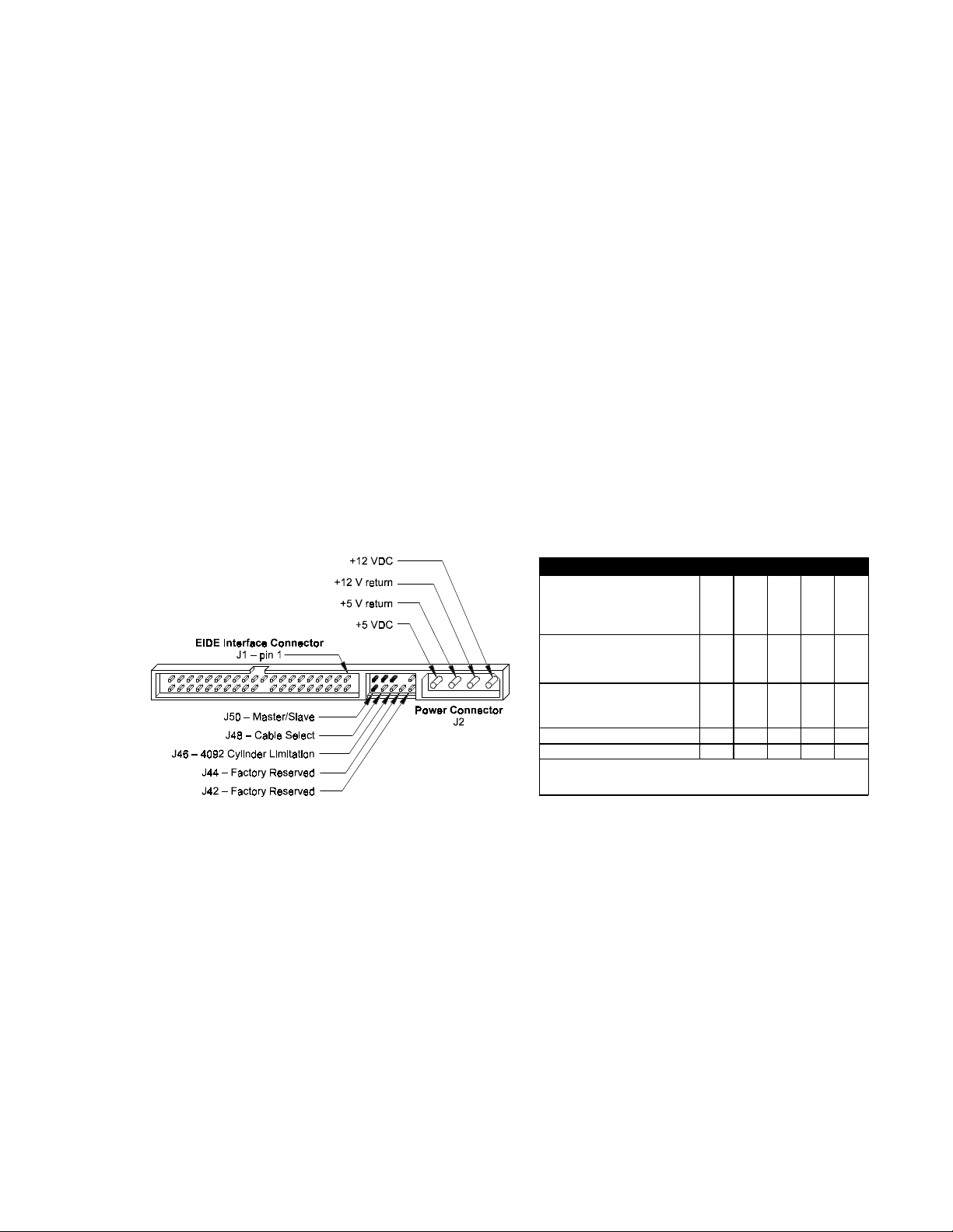
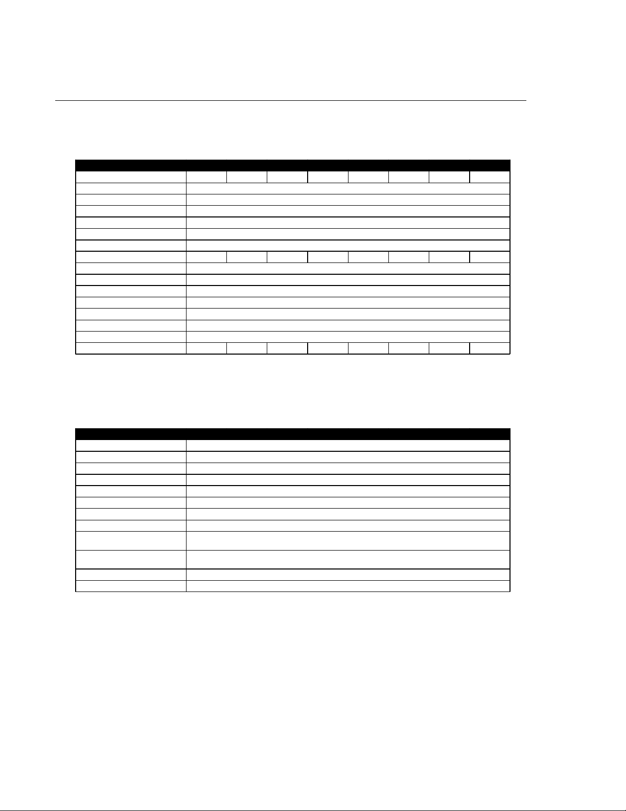
Jumper Location/Configuration
Darkened jumper pins indicate factory-installed (default) shunts.
JUMPER CONFIGURATION J50 J48 J46 J44 J42
Master/Slave
Only drive in single drive system*
Maste r in du al drive syst em*
Slave in d ual drive system
Cable Select
Disabled*
Enabled
4092 Cylinde r Limita tion
Disabled*
Enabled
Factory Reserved
Factory Reserved
Key
* = De f au l t J = Jumpered O = Op en
J
J
O
O
J
O
J
O
Figure 2-1
PCBA Jumper Location and Configuration
4092 Cylinder Limitation
On some older BIOS', primarily those that auto-configure the disk drive, a hang may occur when the drive cylinder value
exceeds 4096. The 4092 Cylinder Limitation jumper reduces the capacity in the Identify Drive to 4092 allowing large
capacity drives to work with older BIOS'. A software driver is required to access the full capacity of the drive.
O
2 – 15
PRODUCT SPECIFICATIONS
Product Specifications
Configuration
MODE L 87000D8 86480D8 85250D6 84320D5 83500D4 83240D4 82560D3 81750D2
Formatted Capacit y (LBA Mode) 7,000 MB 6,480 MB 5,250 MB 4,320 MB 3,500 MB 3,240 MB 2,560 MB 1,750 MB
Integrated Controller/Interface ATA-4/EIDE
Encoding Method RLL 8,9
Interleave 1:1
Servo System Embedded
Buffer Size/Type 256 KB/EDO DRAM
Data Zones per Surface 16
Data Surfaces/Heads 8 8 6 5 4 4 3 2
Aerial Density 1,200 Mb/in
Tracks per Surface (Cylinders) 7,825
Track Density 7,797 tpi
Flux Density 138-172 kfci
Recording Density 123-153 kbpi
Bytes per Sector/Block 512
Sectors per Track 156-249
Sectors per Drive 13,678,880 12,656,250 10,259,160 8,437,500 6,839,440 6,328,125 5,001,728 3,419,720
SECTION 3
2
Performance
MODE L 87000D8 86480D8 85250D6 84320D5 83500D4 83240D4 82560D3 81750D2
Seek Times (Typical)
Track to Track 1.2 ms
Average < 10.0 ms
Maximum 18 ms
Average Latency 5.77 ms
Rotational Speed (±0.1%) 5,200 RPM
Controller Command Overhead < 0.5 ms
Data Transfer Rate
To/from Interface
(UltraDMA - Mode 2)
To/from Interface
(PIO 4/Multi-word DMA - Mode 2)
To/from Media Up to 14.0 MB/sec
Start Time (0 to Drive Ready) 7.3 sec typical
33.0 MB/sec
16.7 MB/sec
3 – 16
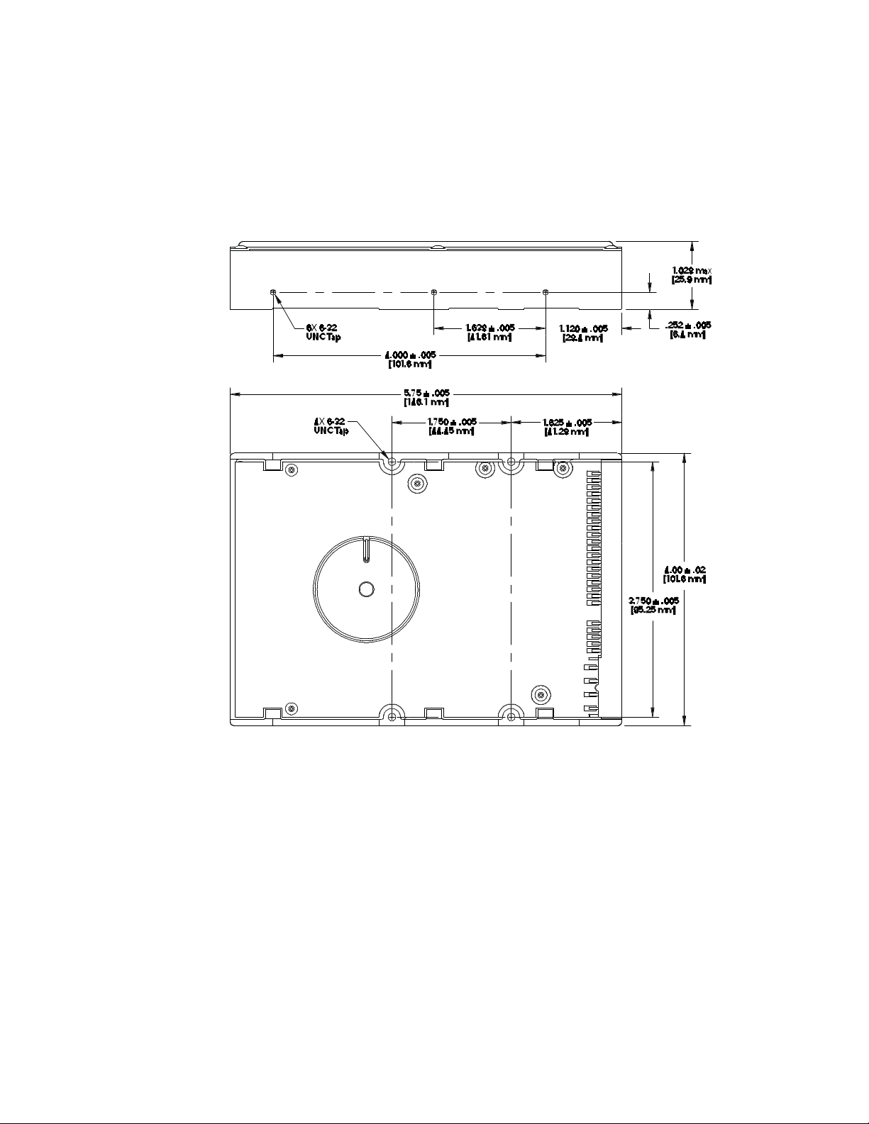
Physical Dimensions
Height 1.00 inches [25.4 mm]
Length 5.75 inches [146.1 mm]
Width 4.00 inches [101.6 mm]
Weight 1.2 pounds [0.5 kg]
PRODUCT SPECIFICATIONS
Outline and Mounting Dimensions
Figure 3 - 1
3 – 17
PRODUCT SPECIFICATIONS
Power Requirements (Average)
MODE 12V ± 8% 5V ± 5% POWER
Spin-up (peak) 1058 mA 260 mA 12.7 W
Active 234 mA 400 mA 4.8 W
Seek 530 mA 418 mA 8.5 W
Read/Write 237 mA 430 mA 5.0 W
Idle 232 mA 224 mA 3.9 W
Standby 2 mA 140 mA 0.7 W
Sleep 2 mA 80 mA 0.4 W
Power Mode Definitions
Active
The drive is spinning and most circuitry is powered on. The drive is capable of responding to read commands in the
shortest possible time. Read/Write heads are positioned over the data area.
Idle
The drive is spinning, the actuator is parked and powered off and all other circuitry is powered on. The drive is capable of
responding to read commands within 40 ms.
Read/Write
Data is being read from or written to the drive.
Spin-up
The drive is spinning up following initial application of power and has not yet reached full speed.
Sleep
This is the lowest power state. The interface becomes inactive. A software or hardware reset is required to return the drive
to Active.
Standby
The spin motor is not spinning. The drive will leave this mode upon receipt of a command that requires disk access. The
time-out value for this mode is programmable. The buffer is active to accept write data.
Seek
A random access operation by the disk drive.
Environmental
PARAMETER OPERATING NON-OPERATING/STORAGE
Temperature 5° C to 55° C Low temperature (-40° C) per MIL-STD-810E, Method 502.3.
High temperature (71° C) per MIL-STD-810E, Method 501.3,
Climatic Category; Hot-induced conditions.
Thermal Gradient (maximum) 25° C per hour 25° C per hour
Relative Humidity 5% to 95% (Non-condens ing)
Wet Bulb 27° C maximum
Altitude -200 to 10,000 feet (with any
naturally occurring temperature
and humidity within this range)
Per MIL-STD-810E, Method 500.3, Low pressure (altitude) Test
Procedure I. Storage; Test Condition 2, Transport aircraft cargo
compartment pressure.
3 – 18
PRODUCT SPECIFICATIONS
Shock and Vibration
PARAMETER OPERATING NON-OPERATING
Mechanical Shock 20 Gs, 2.0 ms, no errors 200 Gs, 2.0 ms, no damage
Random Vibration Per MIL-STD-810E, Method 514.4, Basic transportation,
Swept S ine Vibration
5 - 20 Hz
21 - 300 Hz
Vertical axis PSD profile.
10 Hz at 0.0125 G
40 Hz at 0.0125 G
500 Hz at 0.000125 G
0.049 inches double amplitude
1.0 G peak amplitude
2
/Hz
2
/Hz
2
/Hz
Per MIL-STD-810E, Method 514.4, Basic transportation,
Vertical axis PSD profile.
10 Hz at 0.015 G
40 Hz at 0.015 G
500 Hz at 0.00015 G
2
/Hz
2
/Hz
2
/Hz
Reliability and Maintenance
MTBF –
Maxtor does not differentiate between various usage profiles. (.e. power-on hours, power saving modes, non-operating
periods or operating temperatures within the published specification.)
Start/Stop Cycles – 50,000 (minimum)
This indicates the minimum cycles for reliable start/stop function at a ≥ 60% confidence level.
AFR – 1.7%
The annualized average failure rate (AFR) applies to the period prior to the expiration of component design life, and is
based on failures chargeable to Maxtor. Determination of the AFR takes into account: a.) in-warranty field failure returns
less quality acceptance-related failures and b.) an AFR equaling an exponentially weighted moving and average monthly
failure rate multiplied by 12.
>>
> 500,000 hours
>>
Component Design Life – 5 years (minimum)
Component design life is defined as a.) the time period before identified wear-out mechanisms impact the failure rate, or
b.) the time period up to the wear-out point at which useful component life expires.
Quality Acceptance Rate – 99.85% (<1,500 DPPM)
The quality acceptance rate indicates the percentage of Maxtor products successfully installed by our customers, and/or the
number of defective parts per million (DPPM) encountered during the entire installation process.
Preventative Maintenance – None
Data Reliability
Data Errors (non-recoverable)* – < 1 per 1013 bits read
Seek Errors – < 1 per 106 seeks
*Average data error rate allowed with all error recovery features activated.
Acoustic Noise
Recorded during Active/Idle mode. Average
Sound power (per ISO 7779, 10 microphone) 37 dBA
EPA Energy Star Compliance
Maxtor Corporation supports the goals of the U.S. Environmental Protection Agency’s Energy Star program to reduce the
electrical power consumption of computer equipment.
3 – 19
 Loading...