

Seagate CTD4004H-S, STD14000N, CTD8000H-S, STD18000N, STD124000N DAT Drive Installation Manual
...Page 1

Seagate DAT Drive Installation Manual
English
Page 2

Seagate DAT Drive Installation Manual
Page 3

Seagate DAT Drive Installation Manual
Contents
FCC notice
Introduction 1
Before you begin 1
SCSI cables and connectors 2
Installing an internal DAT drive 3
Configuring an internal DAT drive 3
Mounting an internal DAT drive 10
Connecting power and interface cables 10
Installing an external DAT drive 11
Configuring an external DAT drive 11
Connecting the SCSI interface cable 12
Connecting the power cord 13
Operating and maintaining a DAT drive 14
LED codes 14
Loading a cartridge 17
Unloading a cartridge 18
Initializing a blank DAT cartridge 18
DAT cartridge compatibility 19
Write-protecting a DAT cartridge 20
Cleaning the tape heads 20
Technical support 22
Page 4

Seagate DAT Drive Installation Manual
FCC notice
This equipment generates and uses radio frequency energy and, if not
installed and used in strict accordance with the manufacturer's
instructions, may cause interference to radio and television reception,
which could void the user's authority to operate the equipment. It has
been tested and found to comply with the limits for a Class B digital
device pursuant to Part 15 of FCC Rules, which are designed to provide
reasonable protection against such interference in a residential
installation. However, there is no guarantee that interference will not
occur in a particular installation. If interference does occur, try to
correct it by taking one or more of the following measures:
•
Reorient or relocate the receiving antenna.
•
Increase the separation between the computer and the receiver.
•
Connect the computer into an outlet on a circuit different from that
to which the receiver is connected.
•
Consult the dealer or an experienced radio/television technician for
help.
You may find the following booklet prepared by the Federal
Communications Commission helpful: How to Identify and Resolve
Radio–TV Interference Problems. This booklet (Stock No. 004-00000345-4) is available from the U.S. Government Printing Office,
Washington, DC 20402. Further, this equipment complies with the
limits for Class B digital apparatus in accordance with Canadian Radio
Interference Regulations.
Cet appareil numérique de la classe B est conforme au Règlement sur
brouillage radioélectrique, C. R. C., ch. 1374.
Seagate Publication 10002664-005, July 1997
Page 5
Seagate DAT Drive Installation Manual
Introduction
1
This installation manual contains information on how to
install and operate Seagate
digital audio tape (DAT)
drives. This manual covers DAT drives that support the
DDS (digital data storage), DDS-DC (digital data storage
data compression), DDS-2 and DDS-3 tape formats.
The following table identifies the Seagate DAT drive
models covered by this manual and the tape formats that
they support.
Format DDS DDS-DC DDS-2 DDS-3
Capacity
3.5-inch
internal
models
5.25-inch
internal
models
External
models
2 Gbytes 4* Gbytes 8* Gbytes 24* Gbytes
4320NT
CTD2004H-S
STD12000N
4320RT
CTD2004R-S
STD22000N
4350XT
CTD2004E-S
STD62000N
4324NP
CTD4004H-S
STD14000N
4324RP
CTD4004R-S
STD24000N
4324XP
CTD4004E-S
STD64000N
4326NP
CTD8000H-S
STD18000N
4326RP
CTD8000R-S
STD28000N
4326XP
CTD8000E-S
STD68000N
STD124000N
STD224000N
STD624000N
* Typical capacity, assuming 2:1 data compression. Native capacity is
one half these values.
Before you begin
!
Caution. To avoid data loss, you must clean the
drive heads using a DDS head-cleaning cartridge
after every 25 hours of read/write operation and
whenever the green, cartridge-status LED flashes
during operation.
Page 6

Seagate DAT Drive Installation Manual
!
Caution. Observe the following precautions to
avoid electrostatic damage to your internal tape
drive.
Do not remove the drive from the antistatic bag until
•
you are ready to install it.
Before you remove the drive from the antistatic bag,
•
touch a grounded metal surface to discharge any static
electricity buildup from your body.
Hold the drive only by its edges and avoid direct
•
contact with any electronic components.
If you need to put down the drive, lay it on top of the
•
antistatic bag or place it inside the bag.
SCSI cables and connectors
These DAT drives support connection to a standard,
single-ended SCSI or SCSI-2 interface. A 50-conductor flat
cable or a 25-signal twisted-pair cable may be used to
connect the drive to its SCSI host adapter. The cable
should not be longer than 6 meters (19.5 feet).
2
The internal DAT drive provides a 50-pin, right-angle,
dual-row single-ended SCSI connector attached to the
main PCB at the back of the drive.
The external DAT drive provides two 50-pin, shielded
connectors (ANSI Alternative 2) on the rear panel of the
drive. These connectors consist of two rows of ribbon
contacts spaced 2.16 mm (0.085 in) apart. Either
connector can be used as a SCSI IN or SCSI OUT
connection.
➤ Note: If the DAT drive is the last device in the chain
(or the only device), an external terminator must be
plugged into the unused SCSI connector. To order
terminators through Seagate Express, ask for Seagate
part number 38-9-74000000.
Page 7

Seagate DAT Drive Installation Manual
Installing an internal DAT drive
Internal drive installation involves three main steps:
1. Configuring the drive
2. Mounting the drive
3. Connecting power and interface cables
Internal DAT drives come in two configurations, for
mounting in 3.5-inch or 5.25-inch drive bays, respectively.
Except for mounting the drive, installation procedures are
the same for both types of drives.
Configuring an internal DAT drive
Before you install the tape drive in your computer, you
may need to configure the drive’s SCSI ID or other drive
features. Most features are set using a bank of dipswitches on the underside of the drive. To control SCSI
termination and terminator power or to configure the
drive for remote SCSI address selection, use the jumpers
on the back of the drive (beneath the interface and power
connectors).
3
Dip-switch settings
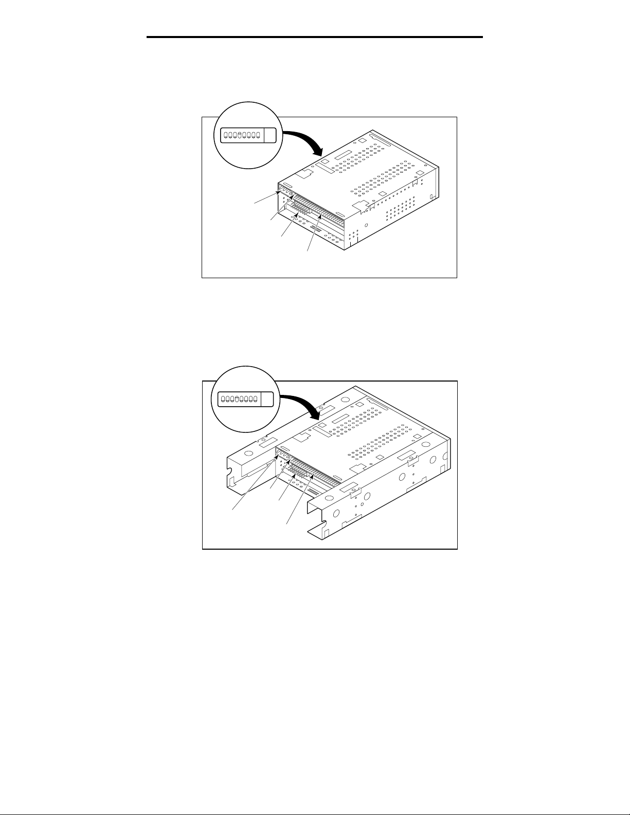
Figures 1 and 2 on page 4 show the location of dip
switches on the underside of 3.5-inch and 5.25-inch
internal drives, respectively. You can access the
switchbank through a rectangular cutout in the drive
shell.
➤ Note. DDS-3 drives have two additional reserved dip
switches on each switchbank. These reserved switches
are not shown in Figures 1 and 2.
Page 8
Seagate DAT Drive Installation Manual
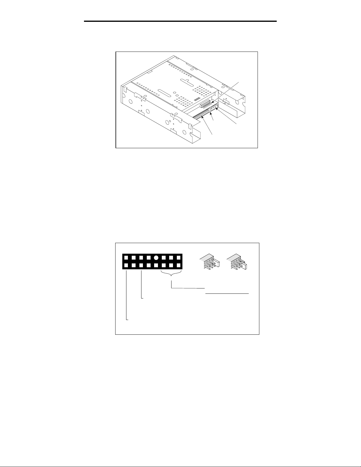
Figure 1
Location of switchbank—3.5-Inch DAT drive
(drive is upside down)
4
1234567
O
Connector
F
F
Power
8
Pin 1
Jumper
Block
SCSI
Connector
Figure 2
Location of switchbank—5.25-Inch DAT drive
(drive is upside down)
1234567
O
8
F
F
Power
Connector
Pin 1
Jumper
Block
Connector
SCSI
Page 9
Seagate DAT Drive Installation Manual
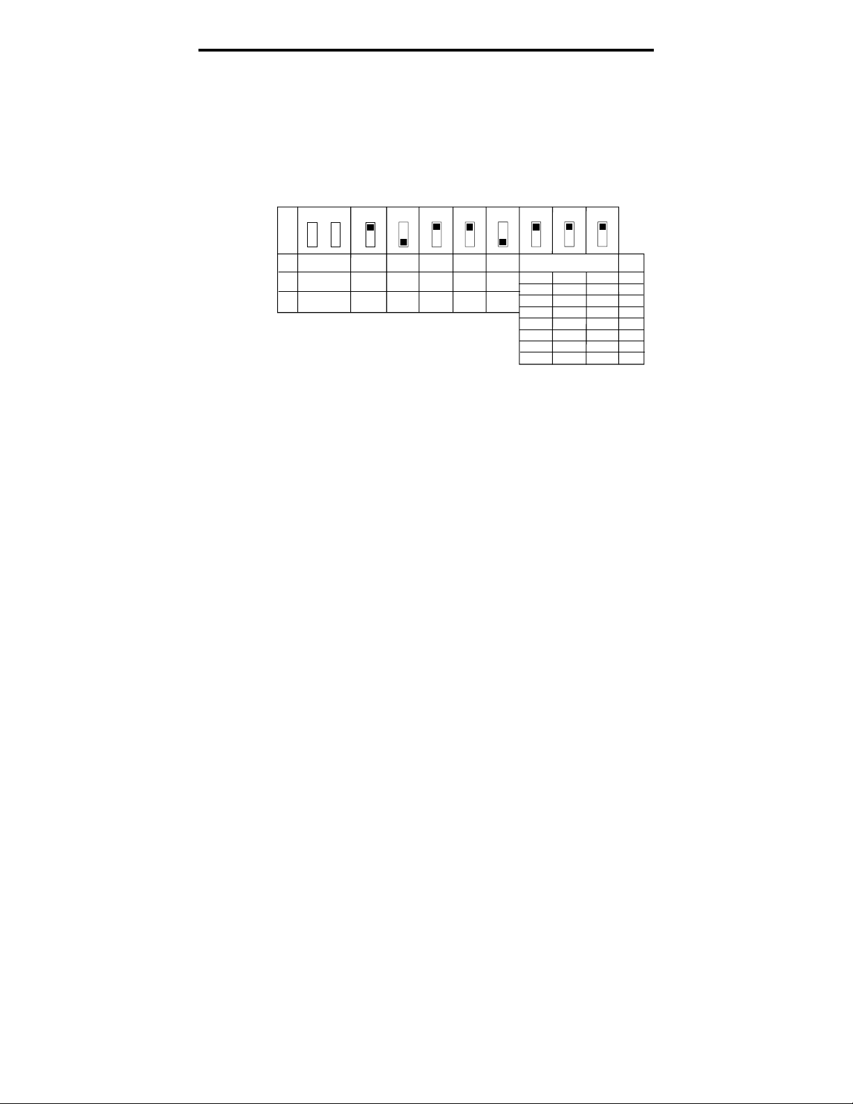
Factory-default settings for each switch are shown in
Figure 3 (only DDS-3 drives have switches S9 and S10).
These settings are described in detail on the following
pages.
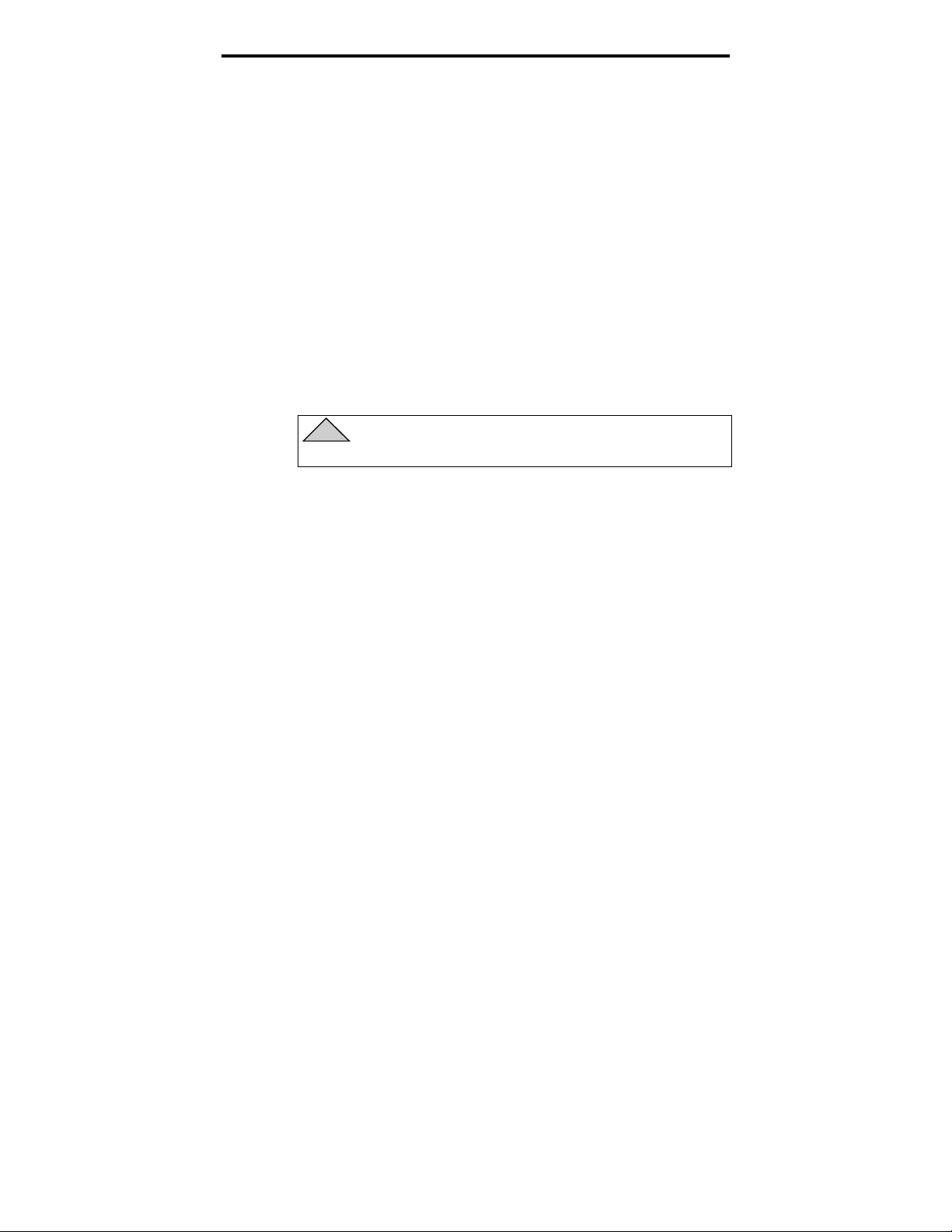
Figure 3
Default dip-switch settings
5
S10
OFF
ON
Reserved
(do not use)
OFF
ON
➤ Note.
S7
S8
S9
Inquiry
Self-test
Disable
Enable
The drive must be turned OFF then ON or a
Archive
Seagate
through
DDS-DC
DDS
DDS Pass-
String
Parity
Disable
Enable
MRS
Mode
MRS
All
SCSI ID Selection
OFF
OFF
OFF
OFF
ON
ON
ON
ON
S2S3S4S5S6
OFF
OFF
ON
ON
OFF
OFF
ON
ON
S1
OFF
ON
OFF
ON
OFF
ON
OFF
ON
SCSI Bus Reset must be received for switch settings to
take effect.
The default dip switch settings for this drive are listed
below:
SCSI ID 0
•
The drive reads or writes both MRS and non-MRS
•
4-mm media.
Parity checking is disabled.
•
DDS-DC data compression is enabled (applies only to
•
models that support data compression).
SCSI ID
0
1
2
3
4
5
6
7
Seagate inquiry string is enabled.
•
Power-on self-test diagnostics are disabled.
•
If these default settings are appropriate for your computer
system and you do not need to enable SCSI termination
for this drive, then turn to “Mounting an internal DAT
drive” on page 10.
Page 10

Seagate DAT Drive Installation Manual
SCSI ID switches (switches S1 through S3)
The three switches S1 through S3 correspond to the SCSI
device address identification bits 0 (LSB) through 2
(MSB), respectively.
➤ Note.
SCSI ID. The SCSI host controller generally uses
ID 7. In some systems, the boot drive uses ID 0.
Media-recognition system (switch S4)
The media-recognition system allows the drive to detect
DDS cartridges that support this feature. Use of non-DDS
media may appear to give satisfactory results, but the
inferior specifications of such media can cause dataintegrity problems.
The S4 switch enables or disables media-recognition
system (MRS) mode. If S4 is ON, the drive reads or writes
both MRS and non-MRS 4-mm media. If S4 is OFF, the
drive reads and writes to MRS media and reads from but
does not write to 4-mm media.
Each SCSI device on a bus must have a unique
6
Parity check enable/disable (switch S5)
The S5 switch enables or disables parity checking for the
SCSI bus. When parity checking is disabled, parity is still
generated by the drive.
If switch S5 is on, parity checking is enabled. The default
setting is parity checking disabled (S5 set to off).
DDS pass-through mode enable/disable (switch S6)
If switch S6 is on, DDS pass-through is enabled (data
compression is disabled).
➤ Note. The function of the S6 switch can be overridden
by the proper SCSI MODE SELECT command issued
from the host computer.
Inquiry string (switch S7)
The S7 switch is used to set the inquiry string used by the
drive. It should be left in its factory-default setting (ON).
Page 11
Seagate DAT Drive Installation Manual
Power-on self-test enable/disable (switch S8)
The S8 switch enables or disables execution of power-on
self-test diagnostics when the drive is powered on. If S8 is
ON, the drive responds to SCSI commands only after
successful completion of the self-test (about 5 seconds).
Switches 9 and 10
These switches are only present on DDS-3 drives. They
are reserved and should not be used.
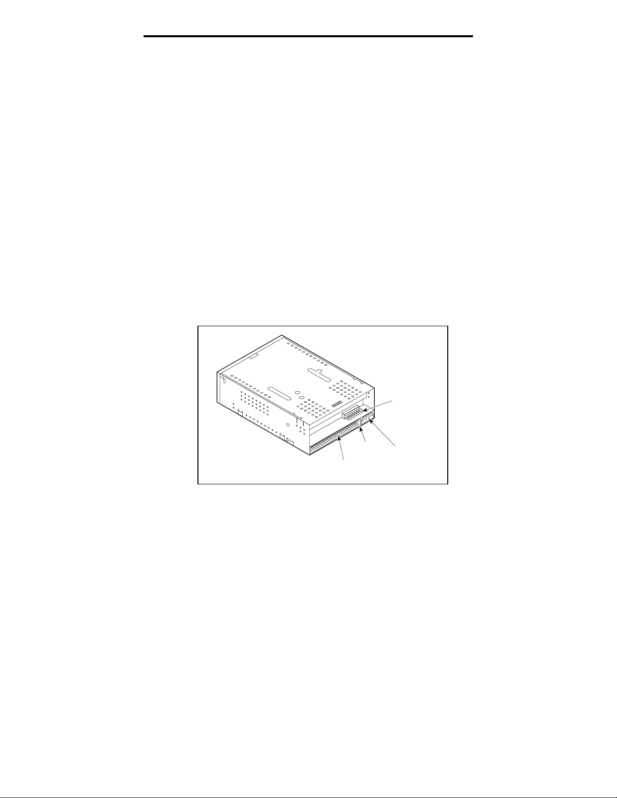
Jumper settings
The configuration jumpers are used to control SCSI bus
termination and terminator power. The jumpers can also
be used for remote SCSI address selection. Figures 4 and 5
show the locations of the jumper blocks for the 3.5-inch
and 5.25-inch internal DAT drives, respectively.
Figure 4
Location of jumper blocks on 3.5-Inch internal
drives
7
SCSI
Connector
Pin 1
Jumper
Block
Power
Connector
Page 12
Seagate DAT Drive Installation Manual
Figure 5
Location of jumpers for 5.25-inch drives
Jumper
Block
8
Pin 1
SCSI
Connector
Power
Connector
Settings for each jumper are shown in Figure 6 below.
These settings are described in detail on the following
page. The default settings are:
Terminator power is disabled.
•
Active termination is disabled.
•
Figure 6
Jumper configurations for internal DAT drives
15
Termination Power ON
(Jumper on pins 15-16)
9 7654321
8
10
1211141316
SCSI ID
ActiveTerminator
Enabled
(Jumper on pins 11-12)
Jumper ON
Pins
Pins
5-6
3-4
OFF OFF 0OFF
OFF OFF 1ON
OFF ON 2OFF
OFF ON 3ON
ON OFF 4OFF
ON OFF 5ON
ON ON 6OFF
ON ON 7ON
Jumper OFF
SCSI
Pins
1-2
ID
Page 13
Seagate DAT Drive Installation Manual
Enabling SCSI termination
Active SCSI termination is disabled as the factory default.
If you need to enable active termination on the drive,
place a jumper on pins 11 and 12.
➤ Note. You need to enable the active termination if the
drive is the only device on the SCSI bus or if it is the
last device on the bus.
Terminator power
You can enable terminator power if needed for
terminators or other SCSI devices through a jumper
placement. The factory default for internal drives is that
terminator power is disabled. To enable terminator power,
place a jumper firmly over pins 15 and 16, as shown in
Figure 6.
!
Caution. If the jumper is installed, be careful not
to short the TERMPWR signal to ground.
9
The drive contains a terminator power fuse to prevent
damage to drive components in case the terminator power
is shorted. If terminator power is enabled and the SCSI
cable is connected upside down for example, this fuse may
blow to prevent damage to the drive. If this occurs, the
drive will not longer supply terminator power to the bus.
To replace the fuse, you must return the drive to an
authorized repair facility.
Remote SCSI Address Selection
You can use pi ns 1 through 6 to rem o t e ly s e l ect the SCSI
address. To do so, install a remote SCSI ID switch and
connect it t o pi ns 1 t hro ugh 6 . Pi ns 1 a nd 2 conf i gure b i t 0 ;
pins 3 and 4 configure bit 1; and pins 5 and 6 configure bit 2.
➤ Note. If you use this method for ID selection, set
switches S1 through S3 to the OFF position (see
Figure 3 on page 5.)
Page 14

Seagate DAT Drive Installation Manual
Mounting an internal DAT drive
You can install your Seagate internal DAT drive
horizontally or on its side.
Mount the drive using two M3.0 metric screws on each
side of the drive. Do not use screws longer than 4 mm or
you may damage the drive. The 3.5-inch drive has four
screw holes on the bottom and five on each side. The 5.25inch drive has four screw holes on the bottom and six on
each side.
Connecting power and interface cables
Attach the power and SCSI interface cables to the
connectors on the back of the drive. Figure 4 on page 7
shows the locations of these connections for the 3.5-inch
drives, and Figure 5 on page 8 shows these connections for
the 5.25-inch drives.
10
➤ Note.
The recommended power mating connector for this drive
is an AMP 1-48024-0 housing with AMP 60617-1 pins or
equivalent.
Turn off all power before inserting connectors.
Pin 1 on the SCSI connector is to your right as you
look at the back of the drive (see Figure 4 or 5). Your
SCSI cable should have pin 1 highlighted by a colored
stripe. Be sure to align pin 1 on the cable with pin 1
on the drive, or the drive may not work.
Page 15

Seagate DAT Drive Installation Manual
Installing an external DAT drive
The Seagate external DAT drive is a compact external
unit that connects to the host computer as a turnkey
subsystem. External drive installation involves three
main steps:
1. Configuring the drive
2. Connecting the SCSI interface cable
3. Connecting the power cord
Configuring an external DAT drive
The following is the default configuration for Seagate
external DAT drives:
The drive reads or writes both MRS and non-MRS
•
4-mm media.
Parity checking is disabled.
•
DDS-DC data compression is enabled (applies only to
•
models that support data compression)
11
The power-on self-test diagnostics of the drive are
•
disabled.
Termination power is supplied to the SCSI bus.
•
➤ Note. Some configuration settings in the EEPROM
can be changed using the SCSI Mode Select command.
SCSI command information for these drives is
provided in the product description manual.
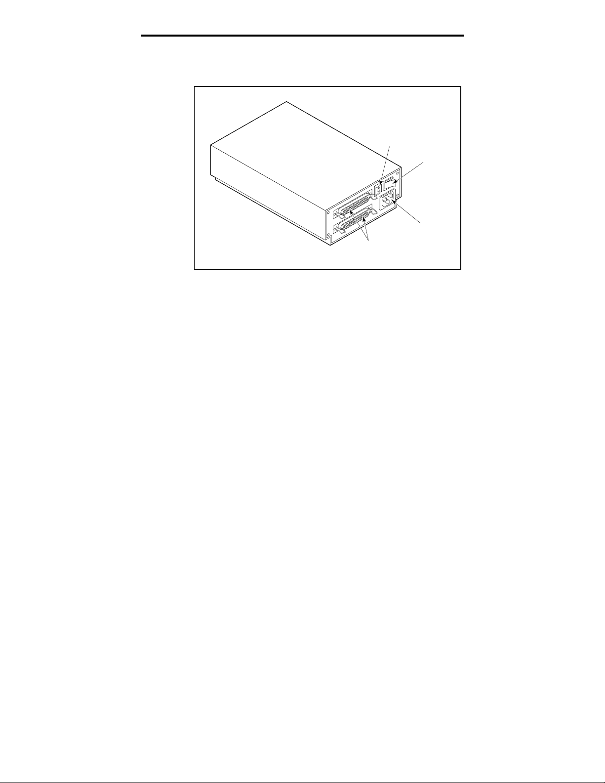
Setting the SCSI ID
Make sure that the drive is turned off; then set the SCSI
ID for the drive using the + and – push-button switch on
the back of the external drive. Figure 7 on page 12 shows
this switch, as well as the two SCSI interface connectors,
on/off switch, and the power-cord connector.
➤ Note. The drive must be restarted, or a bus reset
must occur for any change in SCSI ID to take effect.
Page 16
Seagate DAT Drive Installation Manual
Figure 7
Rear panel of external DAT drives
Connecting the SCSI interface cable
6
SCSI
Connectors
Push
Switch
ON/OFF
Switch
Power
Connector
12
Seagate’s external DAT drives have two SCSI connectors
to allow daisy chaining, as shown in Figure 7. You can use
either connector to attach the drive to a host computer or
to another SCSI device.
➤ Note. Turn off all power before connecting or
disconnecting cables or terminating plugs.
If the drive is the last drive or the only drive in a SCSI
chain, you must install a terminating plug on the unused
SCSI connector. See Figure 8 on the following page for an
explanation of SCSI termination. You can purchase a
terminating plug from Seagate Express (Seagate part
number 38-9-74000000).
Page 17
Seagate DAT Drive Installation Manual
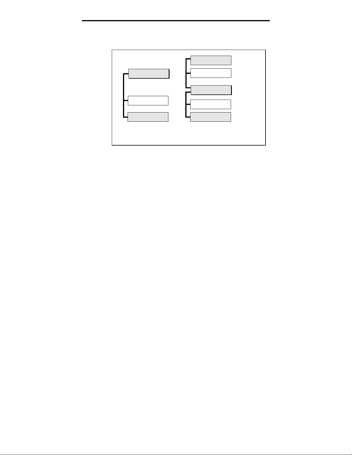
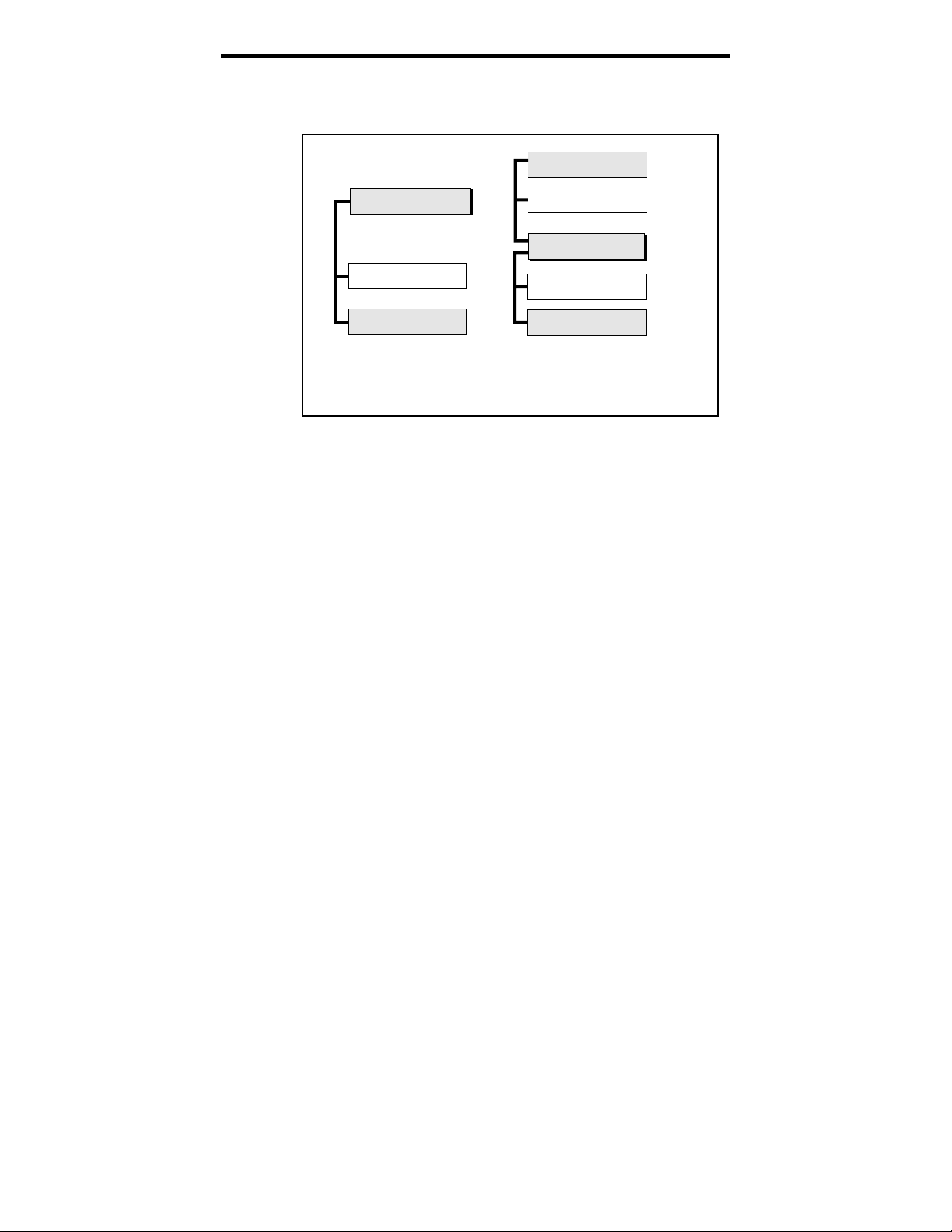
Figure 8
Diagram of SCSI chain with termination
External SCSI device
(termination enabled)
13
SCSI Controller
(termination enabled)
Internal SCSI device
Internal SCSI device
(termination enabled)
Example 1: SCSI termination
in a system that has only
internal SCSI devices.
Connecting the power cord
Attach the power cord securely to the power connector on
the back of the drive. The location of the power connector
is shown in Figure 7 (on the previous page).
External SCSI device
SCSI Controller
Internal SCSI device
Internal SCSI device
(termination enabled)
Example 2: SCSI termination
in a system that has both
internal and external SCSI devices.
Page 18
Seagate DAT Drive Installation Manual
Operating and maintaining a DAT drive
This section describes how to use your internal or external
Seagate DAT drive. It explains the meaning of the various
lights on the front of the drive. It also describes how to use
and care for DAT cartridges.
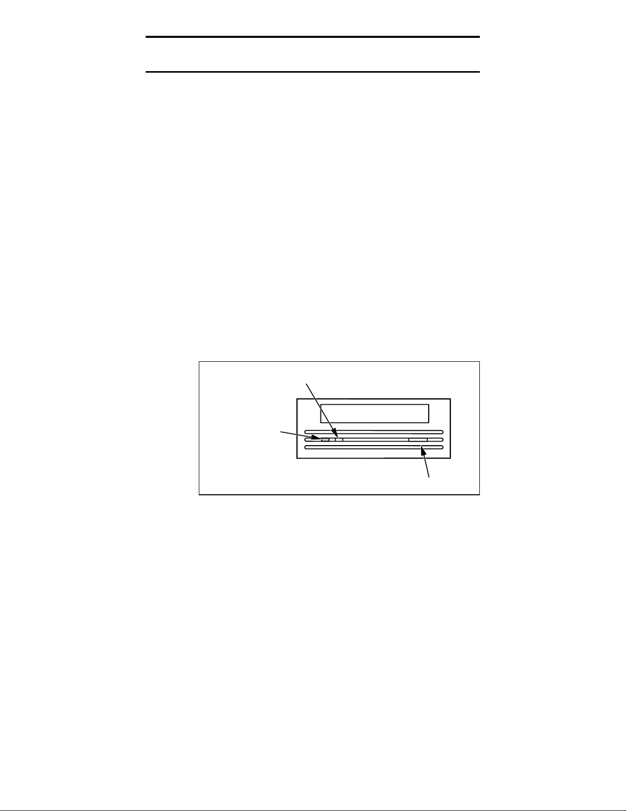
LED codes
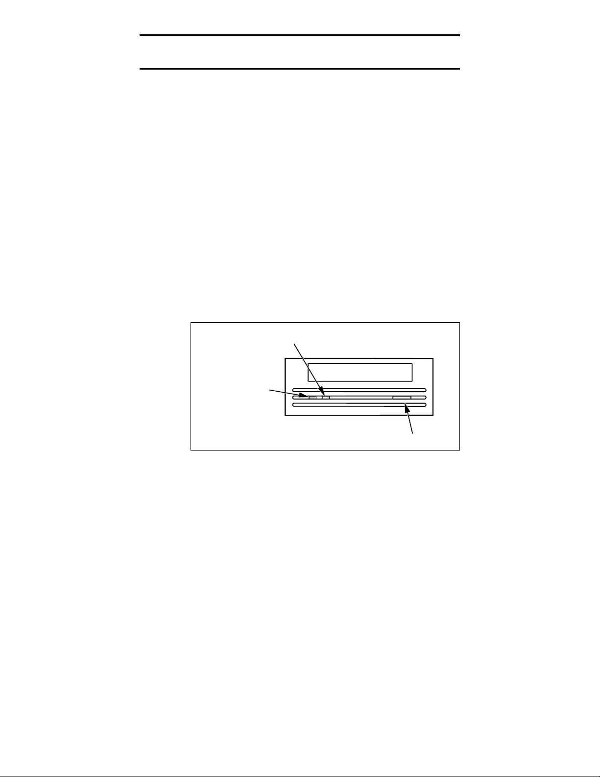
As shown in Figures 9 and 10, the front panel of Seagate
DAT drives contains two rectangular lights (LEDs). These
two indicators provide information about both normal and
error conditions. The yellow rectangular LED indicates
the condition of the tape drive. The green LED indicates
the condition of the tape cartridge.
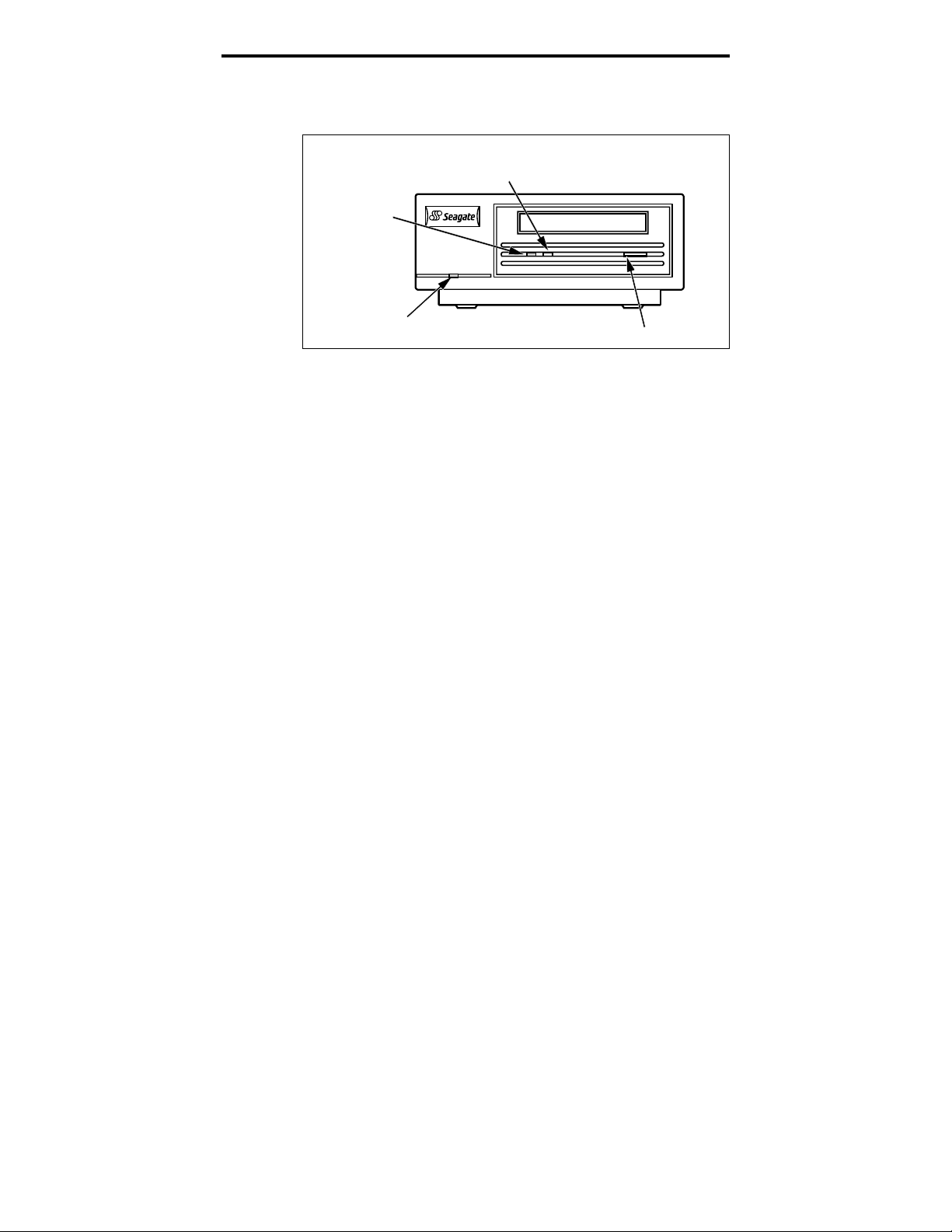
➤ Note. External DAT drives also contain a round,
green power-on LED on the front panel.
Figure 9
Front panel of internal DAT drive
14
Drive Status
(yellow)
Cartridge Status
(green)
Cassette Insertion Slot
Eject Button
Page 19
Seagate DAT Drive Installation Manual
Figure 10
Front panel of external DAT drive
Drive Status
(yellow)
Cartridge
Status
(green)
15
Cassette Insertion Slot
(green)
Drive status LED
The Drive Status LED is yellow and indicates the
following conditions:
If the Drive Status light is ON continuously, the
•
drive is reading or writing the tape (that is, SCSI or
DAT activity is present). If you push the eject button
while the Drive Status LED is ON, you may lose
data.
➤ Note. During a SCSI PREVENT MEDIA REMOVAL
command, the Drive Status LED is always ON.
If the drive status light is flashing rapidly, a
•
hardware fault has occurred. If this occurs
immediately after power-on and you have enabled the
power-on self-test (through a jumper setting), the
power-on self-test may have failed and the drive will
not operate.
Power
Eject Button
Page 20

Seagate DAT Drive Installation Manual
Cartridge status LED
The green, rectangular Cartridge Status LED indicates
the following conditions:
If the Cartridge Status LED is ON (lit) continuously, a
•
cartridge has been inserted and is operating normally.
If the Cartridge Status LED is flashing slowly, the
•
tape cartridge currently in the drive has generated a
significant number of data retries (beyond a
predefined DDS error threshold). This signal is a
warning only and does not indicate data loss.
If you see this signal, remove the tape and clean the
tape heads using an approved DDS DAT cleaning
cartridge (such as the Seagate Model 91301). If the
LED continues flashing or flashes when ejecting the
cartridge, use a new cartridge for future writes.
➤ Note. As routine maintenance, you should clean the
drive heads after every 25 hours of operation. See
subsequent information about maintenance.
16
If the Cartridge Status LED is flashing slowly in
•
conjunction with the yellow LED, a prerecorded audio
cartridge is inserted and is being played
automatically.
If the Cartridge Status LED is flashing rapidly, the
•
drive could not write the tape correctly (maximum
rewrite count exceeded) and the write operation failed.
First, clean the drive heads using an approved DDS
DAT cleaning cartridge, such as the Seagate Model
91301. If the LED continues flashing, use a new
cartridge for future writes.
Page 21

Seagate DAT Drive Installation Manual
LED Code summary
The following table summarizes LED flash codes for
Seagate DAT drives.
LED color Action Meaning
Yellow
Yellow
Green
Green
Green
Green
Round,
green LED
(external
drives only)
ON (lit) The drive is reading or writing the
tape.
Flashing Rapidly A hardware fault occurred.
ON (lit) A cartridge is inserted and does
generate excessive errors.
Flashing Slowly A cartridge is inserted but generates
excessive errors beyond a
predefined error threshold. (Warning
only)
to clean the heads.
Flashing Slowly (with
yellow LED flashing)
Flashing Rapidly The drive could not write the tape
ON (lit) The external drive is powered on.
A prerecorded audio cartridge is
inserted and is being played
automatically.
correctly. (Error)
cleaning cartridge to clean the
heads.
17
not
Use a DDS cleaning cartridge
Use a DDS DAT
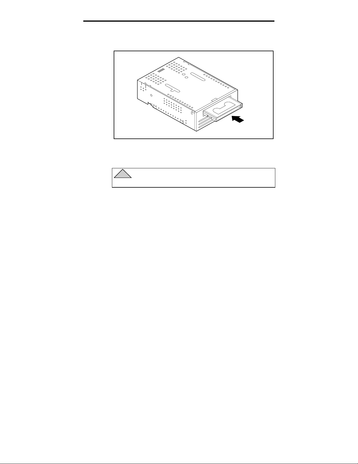
Loading a cartridge
Seagate DAT drives have a front-loading cartridge bay for
easy operation. The drive-bay door opens automatically
when a cartridge is inserted. Figure 11 on the following
page shows a cartridge being inserted into a 3.5-inch
internal drive. After you insert the cartridge, there will be
a brief delay while the drive identifies the cartridge type
and state and moves the tape to the data area.
Page 22
Seagate DAT Drive Installation Manual
Figure 11
Loading a DAT tape cartridge (3.5-inch drive)
Unloading a cartridge
!
Caution. Do not push the eject button while the
Drive Status LED is ON. You may lose data.
18
Make sure that the drive-status light is not lit. Then unload
the cartridge by pressing the eject button. For the location of
the eject button, see Figure 9 on page 14 or Figure 10 on page
15. After you press the eject button, the drive automatically
flushes the drive buffer to tape, updates the system log and
rewinds t he ca rt ri d ge before eje ct i ng i t .
➤ Note. Several seconds may elapse between the time
you press the eject button and the time the cartridge
is ejected. Do not power down the tape drive or the
host computer during this time.
Initializing a blank DAT cartridge
When you insert a blank cartridge into the drive for the
first time, the drive takes about 10 to 12 seconds to
determine that the tape is blank. The drive will
automatically initialize the tape the next time it receives a
write command from the host computer. Initializing a
Page 23

Seagate DAT Drive Installation Manual
blank tape takes about 30 seconds. Write operations are
completed during the initializing operation without delay
until all internal buffers are filled.
➤ Note.
complete causes the procedure to abort. The
initialization will restart from the beginning the next
time a WRITE command is received.
➤ Note. The data buffer of the drive is flushed to tape if
a REWIND command is issued, if the eject button is
pushed, or if a delay in SCSI activity occurs. By
default, the delay before the flush occurs is set to one
minute. However, this delay time can be modified by
the host application using a MODE SELECT
command.
Ejecting the cartridge before the initialization is
DAT cartridge compatibility
Seagate DAT drives are designed to use data-grade DDS
DAT cartridges, which comply with ANSI specifications
listed in the “3.81 mm Helical-Scan Digital Computer
Tape Cartridge for Information Interchange,” ANSI
X3B5/89-156 standard.
19
To ensure optimal data integrity and reliability, we
recommend using the following Seagate-qualified, DDS
DAT cartridges:
Model M31300 (60 meters)
•
Model M32000 (90 meters)
•
Model M34000 (120 meters)
•
Model M312000 (125 meters; DDS-3 only)
•
DDS-2 and DDS-3 DAT drives also recognize 120-meter
MP+ cartridges and other MRS cartridges when MRS is
enabled. MRS cartridges have a series of alternate opaque
and clear stripes at the beginning of the tape. These
stripes classify the media as data-grade, rather than
audio-grade. Four recognition holes allow the drive to
identify the type of tape, determine its magnetic
Page 24
Seagate DAT Drive Installation Manual
thickness, and to determine whether the tape is
prerecorded or unrecorded or is a cleaning cartridge.
Other cartridge features that allow the drive to optically
sense cartridge in are Beginning-of-tape and End-of-tape.
➤ Note. A slowly flashing green LED in conjunction
with the yellow LED indicates that a prerecorded
audio tape has been inserted in the drive.
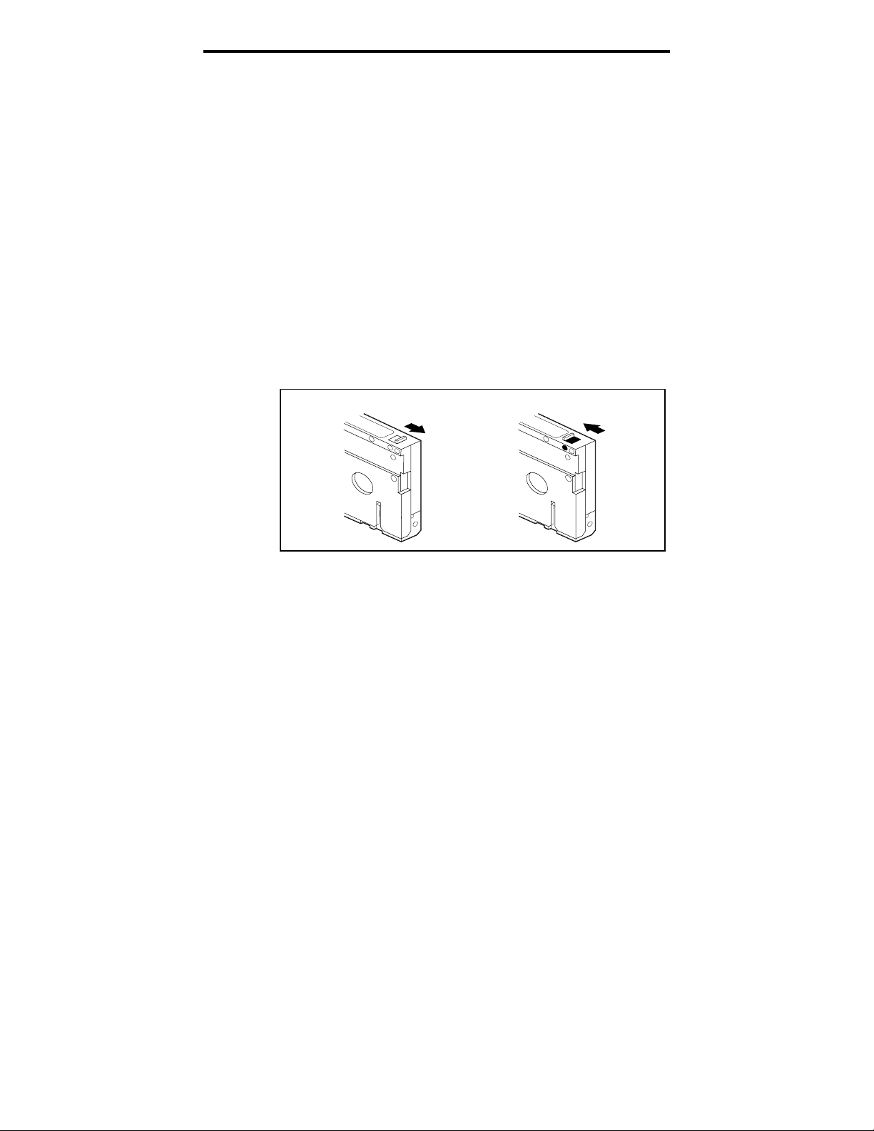
Write-protecting a DAT cartridge
Figure 12 shows how to write-protect or write-enable a DAT
tape using the sliding write-protect tab. You can only write
data to the tape when the tab is in the closed position.
Figure 12
Write-protect tab on the DAT cartridge
20
Cleaning the tape heads
If excessive magnetic dust or debris collects at one or more of
the tape heads, your drive may not be able to read from or
write to tape. To avoid this situation, you must clean the tape
heads on yo ur DA T dri ve i n t he f ol l o wi ng circum stances:
After the first four hours of tape movement of a new
•
cartridge
After every 25 hours of read/write operation
•
Whenever the rectangular, green cartridge-status
•
LED flashes during operation
Write
Enabled
Write
Protected
Page 25

Seagate DAT Drive Installation Manual
➤ Note.
a tape is damaged or is nearing the end of its life. If
cleaning the head does not correct the flashing LED
condition, replace the cartridge. The slowly flashing
LED does not indicate a loss of data, nor does it
indicate SCSI problems.
To clean the tape heads on your DAT drive, use only a
Seagate-qualified DDS DAT cleaning cartridge designed
for DAT drives. Seagate offers a cleaning cartridge, Model
91301 that you can order from Seagate Express (five per
package).
After you insert the cleaning cartridge, the drive detects
that the cartridge is a cleaning cartridge, then loads and
runs the cartridge for about 30 seconds. When cleaning is
complete, the drive ejects the cartridge.
A slowly flashing green LED may indicate that
21
➤ Note.
➤ Note. Do not use an audio DAT cleaning cartridge.
Each time the cleaning cartridge is loaded, a
new, unused portion of cleaning tape is advanced over
the entire tape path. The drive does not rewind a
cleaning cartridge. After about 30 cleaning cycles, the
entire tape is used, and you must purchase a new
cleaning cartridge.
If you insert a cleaning tape that has been used up,
the drive ejects the tape without completing a cleaning
operation. This process takes just under 25 seconds.
The drive cannot recognize it.
Page 26

Seagate DAT Drive Installation Manual
Technical support
If you experience problems installing or using your DAT drive,
contact one of the technical support services listed below.
22
SeaFONE
:
1-800-SEAGATE (1-800-732-4283)
International customers please call 408-456-4496.
SeaNET:
Seagate’s World Wide Web home page—
http://www.seagate.com
Seagate CompuServe Forum:
Online technical support for Seagate
products on CompuServe. Type
SeaBOARD:
Seagate’s automated computer bulletin board system,
available 24 hours daily. Set your modem to 9,600 baud, eight
data bits, no parity and one stop bit (8-N-1).
Australia 61-2-9756-2359 England 44-1628-478011
France 33 1-48 25 35 95 Germany 49-89-140-9331
Taiwan 886-2-719-6075 USA 408-456-4415
Thailand 662-531-8111
SeaFAX:
You can use a touch-tone telephone to access Seagate’s
automated FAX system to receive technical support information
by return FAX. This service is available 24 hours daily.
Australia 61-2-9756-5170 England 44-1628-894084
USA 1-800-SEAGATE or 408-456-4496
Seagate Technical Support FAX:
technical support specialists 24 hours daily. Responses are sent
during local business hours.
Australia 61-2-9725-4052 England 44-1628-890660
France 33 1-46 04 42 50 Germany 49-89-1430-5100
Hong Kong 852-2368 7173 Japan 81-3-5462-2979
Korea 82-2-556-7294/4251 Singapore 65-488-7528
Taiwan 886-2-715-2923 USA 408-944-9120
go Seagate
.
You can FAX questions or comments to
Seagate e-mail Technical Support:
comments to:
Seagate Technical Support:
tapesupport@seagate.com
For one-on-one help, you can talk to a
technical support specialist during local business hours.
Australia 61-2-9725-3366 England 44-1628-894083
France 33 1-41 86 10 86 Germany 49-89-140-9333
Hong Kong 852-2368 9918 Korea 82-2-556-8241
Singapore 65-488-7584 Taiwan 886-2-514-2237
USA 1-800-SEAGATE or 408-456-4496
SeaTDD:
Technical support for users of a telecommunications device for
the deaf (TDD): 408-944-9121
You can e-mail questions or
Page 27

Seagate DAT-Laufwerk Installationshandbuch
Deutsch
Page 28

Seagate DAT-Laufwerk Installationshandbuch
Page 29

Seagate DAT-Laufwerk Installationshandbuch
Inhalt
FCC Anmerkung
Einführung 1
Bevor Sie beginnen 1
SCSI-Anschlußkabel und -Steckplätze 2
Installation eines internen DAT-Laufwerks 3
Konfiguration eines internen DAT-Laufwerks 3
Einbau eines internen DAT-Laufwerks 10
Anschluß der Strom- und Schnittstellenkabel 10
Installation eines externen DAT-Laufwerks 11
Konfiguration eines externen DAT-Laufwerks 11
Anschluß des SCSI-Schnittstellenkabels 12
Anschluß des Stromkabels 13
Bedienung und Wartung eines DAT-Laufwerks 14
LED-Anzeigen 14
Laden einer Kassette 17
Entfernen einer Kassette 18
Initialisierung einer neuen DAT-Kassette 19
DAT-Kassetten-Kompatibilität 19
Schreibschutz einer DAT-Kassette 20
Reinigung der Magnetköpfe 21
Technischer Support 23
Page 30

Seagate DAT-Laufwerk Installationshandbuch
FCC Anmerkung
Dieses Gerät verwendet und verursacht hochfrequente Signale. Es muß in
Übereinstimmung mit den Herstellerangaben installiert und benutzt
werden. Unsachgemäße Verwendung kann beim Radio- und
Fernsehempfang Störungen verursachen, so daß dem Anwender das
Nutzungsrecht für das Gerät entzogen werden kann. Das Laufwerk
wurde getestet und erfüllt die Anforderungen für eine digitale Einheit der
Klasse B, nach Abschnitt 15 der FCC Norm. Diese Regeln wurden
aufgestellt, um bei einer lokalen Installation gegen Interferenzen
bestmöglich zu schützen. Es wird keine Garantie übernommen, wenn bei
anderen Installationen Funkstörstrahlungen erzeugt werden. Sollten
Interferenzen auftreten, können sie eventuell durch eine der folgenden
Maßnahmen beseitigt werden:
•
Veränderung der Ausrichtung und/oder Plazierung der Antenne
•
Vergrößerung des Abstandes zwischen Computer und Empfänger
•
Verbinden Sie den Computer mit einem Ausgang auf einem anderen
Schaltkreis, so daß Computer und Receiver nicht auf dem gleichen
Schaltkreis angeschlossen sind.
•
Wenden Sie sich für weitere Hilfe an den Fachhändler oder einen
autorisierten Radio/Fernseh-Techniker.
Die Broschüre ‘How to Identify and Resolve Radio-TV Interference
Problem’ des FCC gibt Ihnen weitere Hilfen. Diese Broschüre (Stock No.
004-000-00345-4) ist erhältlich beim U.S. Government Printing Office,
Washington, DC 20402. Dieses Gerät erfüllt auch die Richtlinien der
Klasse B für digitale Geräte in Übereinstimmung mit den Canadian Radio
Interference Regulations.
Cet appareil numérique de la classe B est conforme au Règlement sur
brouillage radioélectrique, C. R. C., ch. 1374.
Seagate Publication 10002664-005, Juli 1997
Page 31

Seagate DAT-Laufwerk Installationshandbuch
Einführung
1
Dieses Handbuch enthält Informationen zur Installation
und zum Einsatz von Seagate
digital audio tape (DAT)Laufwerken. Es schließt DAT-Laufwerke mit ein, die
folgende Formate unterstützen: DDS (digital data
storage), DDS-DC (digital data storage data compression),
DDS-2 und DDS-3.
Die Seagate DAT-Laufwerke und die unterstützten
Magnetbandformate, für die dieses Handbuch zu
verwenden ist, sind in der folgenden Tabelle aufgeführt.
Format DDS DDS-DC DDS-2 DDS-3
Kapazität
3.5-Zoll
interne
Laufwerke
5.25-Zoll
interne
Laufwerke
Externe
Laufwerke
2 Gbytes 4* Gbytes 8* Gbytes 24* Gbytes
4320NT
CTD2004H-S
STD12000N
4320RT
CTD2004R-S
STD22000N
4350XT
CTD2004E-S
STD62000N
4324NP
CTD4004H-S
STD14000N
4324RP
CTD4004R-S
STD24000N
4324XP
CTD4004E-S
STD64000N
4326NP
CTD8000H-S
STD18000N
4326RP
CTD8000R-S
STD28000N
4326XP
CTD8000E-S
STD68000N
STD124000N
STD224000N
STD624000N
* Kapazität bei einer Datenkompression von 2:1. Die normale
Kapazität entspricht der Hälfte dieser Angaben.
Bevor Sie beginnen
!
Achtung!
müssen die Magnetköpfe des Laufwerks mit einer
DDS-Reinigungskassette gesäubert werden. Die
Reinigung muß spätestens nach 25 Stunden
Schreib/Lese-Betrieb erfolgen oder immer dann,
wenn während des Betriebs die grüne ‘CartridgeStatus-LED’ aufleuchtet.
Um Datenverluste zu vermeiden,
Page 32

Seagate DAT-Laufwerk Installationshandbuch
!
Achtung! Statische Ladung kann die Elektronik
Ihres internen Laufwerks beschädigen.
Berücksichtigen Sie folgende Hinweise, um
Schäden an Ihrem Laufwerk zu vermeiden.
Entfernen Sie die antistatische Schutzhülle erst, wenn
•
Sie mit der Installation beginnen.
Berühren Sie eine geerdete Metalloberfläche, bevor Sie
•
das Gerät aus der antistatischen Schutzhülle nehmen.
Damit bauen Sie mögliche statische Ladung ab.
Halten Sie das Laufwerk nur an den Kanten, und
•
berühren Sie keine der elektronischen Komponenten.
Wenn Sie das Laufwerk ablegen, legen Sie es auf oder
•
in die antistatische Schutzhülle.
SCSI-Anschlußkabel und -Stecker
Die DAT-Laufwerke werden an einer normalen SCSIoder SCSI-2-Schnittstelle angeschlossen. Für die
Verbindung kann ein 50-poliges Flachbandkabel oder ein
25-phasiges Twisted-pair-Kabel verwendet werden. Das
Kabel sollte nicht länger als sechs Meter sein.
2
Das interne DAT-Laufwerk hat einen 50-poligen, rechtwinkligen, zweireihigen single-ended SCSI-Stecker auf
der Rückseite des Gerätes.
Das externe DAT-Laufwerk hat auf der Rückseite zwei
abgeschirmte 50-polige An schlüsse (ANSI - Alte rnative 2).
Diese Konnektoren bestehen aus einer zweireih ig en
Kontaktleiste in einem Abstand v o n 2,16 mm. Jede
Buchse kann als SCSI-IN- oder SCSI-OUT-Verbindung
benutzt werden.
➤ Anmerkung. Ist d as DA T-La ufwerk da s l etz te (o der
einzige) Gerät in der SCSI-Kette, muß ein externer
Terminator an der freien SCSI-Verbindung angeschlossen
werden. Termi nato ren können b ei S eaga te unt er der
Kennnummer P/N 38- 9-74000000 bestellt werden.
Page 33

Seagate DAT-Laufwerk Installationshandbuch
Installation eines internen DAT-Laufwerks
Die Installation eines internen Laufwerks erfolgt in drei
Hauptschritten:
1. Konfiguration des Laufwerks
2. Einbau des Laufwerks
3. Verbindung der Strom- und Schnittstellenkabel
Interne DAT-Laufwerke werden in zwei Konfigurationen
ausgeliefert: für den Einbau in 3.5-Zoll- oder 5.5-ZollSteckplätze. Beide Typen werden – außer beim Einbau –
auf die gleiche Weise installiert.
Konfiguration eines internen DAT-Laufwerks
Vor dem Einbau in den Computer müssen die SCSI-ID des
Laufwerks oder weitere Einstellungen angepaßt werden.
Die meisten Funktionen werden mit den Schaltern auf
der Unterseite des Gerätes eingestellt. Um die SCSITerminatoren und die Terminator-Stromversorgung
einzustellen oder um das Laufwerk für die automatische
Adreßzuweisung zu konfigurieren, verwenden Sie die
Jumper auf der Geräterückseite (in der Nähe der
Schnittstellen- und Stromkabel).
3
Dip-Schalter-Einstellungen
Abbildung 1 und 2 auf der folgenden Seite zeigen die Lage
der Dip-Schalter auf der Unterseite eines internen 3.5Zoll- beziehungsweise 5.25-Zoll-Laufwerks. Sie erreichen
die Schalter durch einen rechteckigen Ausschnitt im
Laufwerksgehäuse.
➤ Anmerkung. DDS-3-Laufwerke haben auf jeder
Schalterreihe zwei zusätzliche reservierte DipSchalter. Diese reservierten Schalter sind auf
Abbildung 1 und 2 nicht eingezeichnet.
Page 34

Seagate DAT-Laufwerk Installationshandbuch
Abbildung 1
Lage der Dip-Schalter – 3.5-Zoll-DAT-Laufwerk
(Laufwerk liegt mit der Oberseite nach unten)
4
1234567
O
Stromanschluß
8
F
F
Pin 1
Jumper-
Block
SCSI-
Anschluß
Abbildung 2
Lage der Dip-Schalter – 5.25-Zoll-DAT-Laufwerk
(Laufwerk liegt mit der Oberseite nach oben)
1234567
O
8
F
F
Pin 1
Jumper-
Stromanschluß
Block
SCSI-
Anschluß
Abbildung 3 zeigt die Voreinstellung der Schalter. (Nur
DDS-3-Laufwerke haben die Schalter S9 und S10.) Diese
Page 35

Seagate DAT-Laufwerk Installationshandbuch
Einstellungen werden auf den folgenden Seiten detailliert
beschrieben.
Abbildung 3
Standard Dip-Schalter-Einstellungen
5
S8
S9
S10
OFF
ON
(nicht verwenden)
OFF
ON
Reserviert
Selbst-test
Deaktiviert
Aktiviert
➤ Anmerkung.
S7
Inquiry
DDS Pass-
String
through
DDS-DC
Archiv
DDS
Seagate
Damit die Schalter-Einstellungen
Parität
Deaktiviert
Aktiviert
MRS-
Modus
MRS
Alle
SCSI-ID Auswahl
OFF
OFF
OFF
OFF
ON
ON
ON
ON
S2S3S4S5S6
OFF
OFF
ON
ON
OFF
OFF
ON
ON
wirksam werden, muß das Laufwerk AUS- und wieder
EINgeschaltet oder ein Reset des SCSI-Busses
vorgenommen werden.
Die Standard Dip-Schalter-Einstellungen für dieses
Laufwerk:
SCSI ID 0
•
Das Laufwerk liest oder schreibt sowohl auf MRS- als
•
auch auf Nicht-MRS-4-mm-Datenträger.
Paritätskontrolle ist deaktiviert.
•
DDS-DC-Datenkompression ist aktiviert (nur bei
•
Modellen, die Datenkompression unterstützen).
S1
OFF
ON
OFF
ON
OFF
ON
OFF
ON
SCSI-ID
0
1
2
3
4
5
6
7
Seagate Inquiry String ist aktiviert.
•
Die Selbsttest-Diagnose beim Einschalten des Geräts
•
ist deaktiviert.
Sind die vorgegebenen Einstellungen für ihren Computer
richtig, und Sie benötigen für dieses Laufwerk keinen
SCSI-Terminator, dann lesen Sie bei ‘Einbau des internen
DAT-Laufwerks’ auf Seite 10 weiter.
Page 36

Seagate DAT-Laufwerk Installationshandbuch
SCSI-ID-Schalter (Schalter S1 bis S3)
Die drei Schalter S1 bis S3 entsprechen den SCSI-GeräteAdreß-Bits 0 (LSB) bis 2 (MSB).
➤ Anmerkung.
benötigt eine eigene SCSI-ID. Der SCSI-HostController benutzt normalerweise ID 7. In einigen
Systemen verwendet das Boot-Laufwerk die ID 0.
Media Recognition-System (Schalter S4)
Mit dem Media Recognition-System kann das Laufwerk
DDS-Kassetten, die diese Funktion unterstützen,
erkennen. Die Verwendung von Nicht-DDS-Datenträgern
liefert scheinbar zufriedenstellende Ergebnisse, aber
wegen unzureichender Spezifikationen kann es bei diesen
Datenträgern zu Datenintegrationsfehlern kommen.
Der S4-Schalter aktiviert oder deaktiviert das Media
Recognition-System (MRS). Steht S4 auf ‘ON’, liest und
schreibt das Laufwerk MRS- und Nicht-MRS-4mmDatenträger. Steht der Schalter auf ‘OFF’, liest und
schreibt das Gerät auf MRS-Datenträger, aber 4-mmMagnetbänder werden nur gelesen.
Jedes SCSI-Gerät auf einem Bus
6
Paritätskontrolle (Schalter S5)
Mit dem Schalter S5 wird die Paritätskontrolle aktiviert
oder deaktiviert. Bei deaktivierter Paritätskontrolle wird
die Parität weiterhin vom Laufwerk generiert. Die
Voreinstellung ist ‘OFF’ – keine Paritätskontrolle.
DDS-Pass-Through-Modus (Schalter S6)
Steht der Schalter S6 auf ‘ON’, ist DDS-Pass-Through
aktiviert (keine Datenkompression).
➤ Anmerkung. Durch den entsprechenden SCSI
MODE SELECT-Befehl vom Host-Computer kann die
Funktion von S6 überschrieben werden.
Page 37

Seagate DAT-Laufwerk Installationshandbuch
Inquiry String (Schalter S7)
Mit S7 wird der vom Laufwerk genutzte Inquiry String
definiert. Ab Fabrik steht S7 auf ‘ON’.
Selbsttest beim Einschalten des Geräts (Schalter S8)
S8 aktiviert oder deaktiviert die Selbsttest-Diagnose,
wenn das Laufwerk eingeschaltet wird. Steht S8 auf ‘ON’,
antwortet das Laufwerk auf SCSI-Befehle nur nach einem
erfolgreichen Selbsttest (dauert in etwa fünf Sekunden).
Schalter S9 und S10
Diese Schalter gibt es nur bei DDS-3-Laufwerken. Sie
sind reserviert und sollten nicht benutzt werden.
Jumper-Einstellungen
Die Konfigurations-Jumper werden benutzt, um den SCSI
Bus-Terminator und die Terminator-Stromversorgung zu
kontrollieren. Die Jumper können auch für die RemoteZuweisung von SCSI-Adressen benutzt werden. Abbildung
4 und 5 zeigen die Lage der Jumperblöcke bei internen
3.5-Zoll- beziehungsweise 5.25-Zoll-Laufwerken.
7
Abbildung 4
Lage der Jumperblöcke bei internen 3.5-ZollLaufwerken
Jumper-
Block
Pin 1
Stromanschluß
SCSI-
Anschluß
Page 38

Seagate DAT-Laufwerk Installationshandbuch
Abbildung 5
Lage der Jumperblöcke bei internen 5.25-ZollLaufwerken
Die Stellung für jeden Jumper wird in Abbildung 6
gezeigt und auf den nächsten Seiten detailliert
beschrieben. Die Voreinstellungen sind:
Terminator-Stromversorgung ist deaktiviert.
•
Pin 1
SCSI-
Anschluß
Jumper-
Block
Stromanschluß
8
Aktive Termination ist deaktiviert.
•
Abbildung 6
Jumper-Einstellung bei internen DAT-Laufwerken
15
Terminator-stromversorgung
(Jumper 15 und 16 — ‘ON’)
9 7654321
8
10
1211141316
SCSI ID
Terminator aktiviert
(Jumper 11 und 12 — ‘ON’)
Jumper 'ON'
Stifte
Stifte
5-6
3-4
OFF OFF 0OFF
OFF OFF 1ON
OFF ON 2OFF
OFF ON 3ON
ON OFF 4OFF
ON OFF 5ON
ON ON 6OFF
ON ON 7ON
Jumper 'OFF'
SCSI
Stifte
ID
1-2
Page 39

Seagate DAT-Laufwerk Installationshandbuch
SCSI-Termination aktivieren
Bei der Voreinstellung ist SCSI-Termination deaktiviert.
Um das zu ändern, muß auf Pin 11 und 12 ein Jumper
gesetzt werden.
➤ Anmerkung. Die aktive Termination muß aktiviert
werden, wenn das Laufwerk das einzige oder das
letzte Gerät auf dem SCSI-Bus ist.
Terminator-Stromversorgung
Stromversorgung für den Terminator oder andere SCSIGeräte kann durch einen Jumper aktiviert werden. Interne Laufwerke haben voreingestellt, daß die TerminatorStromversorgung deaktiviert ist. Die TerminatorStromversorgung wird mit einem Jumper auf Pin 15 und
16 aktiviert.
!
Achtung! Wenn der Jumper installiert ist, darf
das TERMPWR-Signal nicht geerdet sein.
9
Das Laufwerk hat eine Sicherung für die TerminatorStromversorgung. Damit wird ein Schaden an den
Komponenten verhindert, falls ein Kurzschluß auftritt. Ist
die Terminator-Stromversorgung aktiviert und zum
Beispiel das SCSI-Kabel verkehrt herum installiert,
brennt die Sicherung durch. Damit wird ein Schaden am
Laufwerk verhindert. In diesem Fall liefert das Laufwerk
für den Bus keine Terminator-Stromversorgung mehr.
Die Sicherung kann nur durch eine autorisierte
Reparaturwerkstatt ausgewechselt werden.
Remote SCSI Address-Selection
Pin 1 bis 6 werden verwendet, um Remote SCSI AddressSelection einzustellen. Dazu installieren Sie einen
‘Remote SCSI ID-Schalter’ und verbinden ihn mit Pin 1
bis 6. Pin 1 bis 2 konfigurieren Bit 0, Pin 3 bis 4 Bit 1 und
Pin 5 bis 6 Bit 2.
Anmerkung. Wenn Sie für die ID-Auswahl diese
Methode verwenden, stellen Sie Switch S1 bis S3 auf
‘OFF’ (siehe Abbildung 3, Seite 5).
Page 40

Seagate DAT-Laufwerk Installationshandbuch
Einbau eines internen DAT-Laufwerks
Das Seagate DAT-Laufwerk kann horizontal oder vertikal
eingebaut werden.
Verwenden Sie zum Einbau zwei metrische M3.0Schrauben auf jeder Seite des Laufwerks. Nehmen Sie
keine Schrauben, die länger als 4 mm sind, denn damit
könnte das Gerät beschädigt werden. Das 3.5-ZollLaufwerk hat vier Schraubgewinde an der Unterseite und
fünf an jeder Seite, das 5.25-Zoll-Laufwerk hat vier
Gewinde an der Unterseite und sechs an jeder Seite.
Anschluß der Strom- und Schnittstellenkabel
Verbinden Sie die Strom- und SCSI-Schnittstellenkabel
mit den Anschlüssen an der Geräterückwand. Abbildung
4, Seite 7 zeigt die Lage der Anschlüsse für 3.5-ZollLaufwerke und Abbildung 5, Seite 8 für 5.25-ZollLaufwerke.
10
➤ Anmerkung.
die Stecker anschließen. Pin 1 auf dem SCSIKonnektor befindet sich von hinten betrachtet auf der
rechten Seite des Gerätes (siehe Abbildung 4 und 5).
Beim SCSI-Kabel müßte Pin 1 farbig gekennzeichnet
sein. Überprüfen Sie, ob Pin 1 des Kabels mit Pin 1
des Laufwerks verbunden ist, sonst funktioniert das
Gerät nicht.
Der empfohlene Stromanschlußstecker für dieses
Laufwerk ist ein AMP 1-48024-0-Stecker mit AMP 606171 oder äquivalenten Pins.
Schalten Sie den Strom ab, bevor Sie
Page 41

Seagate DAT-Laufwerk Installationshandbuch
Installation eines externen DAT-Laufwerks
Das externe Seagate DAT-Laufwerk wird mit dem HostRechner als schlüsselfertiges Subsystem verbunden. Die
externe Installation besteht aus drei Hauptschritten:
1. Konfiguration des Laufwerks
2. Anschluß des SCSI-Schnittstellenkabels
3. Anschluß der Stromkabel
Konfiguration eines externen DAT-Laufwerks
Die Voreinstellung für ext e rne S e a ga t e DA T -L a ufwe rke is t :
Das Laufwerk liest und schreibt auf MRS- und Nicht-
•
MRS-4-mm-Datenträger.
Paritätskontrolle ist deaktiviert.
•
DDS-DC-Datenkompression ist aktiviert (nur bei
•
Modellen, die Datenkompression unterstützen).
Die Selbsttest-Diagnose ist deaktiviert.
•
11
Die Terminator-Stromversorgung für den SCSI-Bus
•
ist aktiviert.
➤ Anmerkung.
im EEPROM können mit dem SCSI MODE SELECTBefehl geändert werden. Informationen zu SCSIBefehlen für diese Laufwerke finden Sie im
Produkthandbuch.
Einstellung der SCSI-ID
Schalten Sie das Laufwerk aus. Stellen Sie mit dem
+/-Druckschalter auf der Rückseite des Laufwerks die
SCSI-ID ein. Abbildung 7, Seite 12 zeigt den Schalter, die
beiden SCSI-Interface-Konnektoren, den on/off-Schalter
und den Stromanschluß.
➤ Anmerkung. Damit die Änderungen an der SCSI-ID
wirksam werden, muß ein Reset des Laufwerks oder
des SCSI-Busses durchgeführt werden.
Einige der Konfigurationseinstellungen
Page 42

Seagate DAT-Laufwerk Installationshandbuch
Abbildung 7
Rückansicht externer DAT-Laufwerke
Anschluß des SCSI-Schnittstellenkabels
Druckschalter
SCSI-
Anschluß
6
ON/OFF-
Schalter
Stromanschluß
12
Externe Seagate DAT-Laufwerke verfügen über zwei
SCSI-Verbindungen, um den Anschluß mehrerer
(externer) Laufwerke zu ermöglichen (siehe Abbildung 7,
Seite 12). Beide Konnektoren können für den Anschluß an
den Rechner oder eines anderen SCSI-Geräts verwendet
werden.
➤ Anmerkung. Schalten Sie den Strom aus, bevor Sie
Kabel oder Terminatoren anschließen oder entferrnen.
Ist das Laufwerk das einzige oder das letzte Gerät einer
SCSI-Kette, muß auf dem unbenutzten SCSI-Stecker ein
Terminator angebracht werden. Zur Beschreibung der
SCSI-Termination siehe Abbildung 8, Seite 13. Einen
Terminator erhalten Sie bei Seagate Express (Seagate
part number 38-9-74000000).
Page 43
Seagate DAT-Laufwerk Installationshandbuch
Abbildung 8
Diagramm einer SCSI-Kette mit Termination
Externes SCSI-Gerät
(Anschluß freigegeben)
13
SCSI-Regler
(Anschluß freigegeben)
Internes SCSI-Gerät
Internes SCSI-Gerät
(Anschluß freigegeben)
Beispiel 1: SCSI-Anschluß
bei einem System mit
ausschließlich internen SCSIGeräten.
Anschluß des Stromkabels
Verbinden Sie das Stromkabel mit dem Stromstecker an
der Geräterückwand. Die Lage des Stromsteckers sehen
Sie auf Abbildung 7, Seite 12.
Externes SCSI-Gerät
SCSI-Regler
Internes SCSI-Gerät
Internes SCSI-Gerät
(Anschluß freigegeben)
Beispiel 2: SCSI-Anschluß
bei einem System mit internen
und externen SCSI-Geräten.
Page 44
Seagate DAT-Laufwerk Installationshandbuch
Bedienung und Wartung eines DAT-Laufwerks
Dieser Abschnitt beschreibt, wie Sie Ihr internes oder
externes Seagate DAT-Laufwerk verwenden. Er erklärt
die Bedeutung der verschiedenen Anzeigen auf der
Vorderseite des Gerätes und wie DAT-Kassetten benutzt
und gepflegt werden.
LED-Anzeigen
Wie Abbildung 9 und 10 zeigen, sind auf der Vorderseite
der Seagate DAT-Laufwerke zwei rechteckige
Leuchtdioden (LEDs) angebracht. Diese beiden Anzeigen
informieren über die normalen Bedingungen und Fehler.
Die gelbe LED zeigt den Status des Laufwerks, die grüne
LED den Status der Kassette.
➤ Anmerkung. Externe Laufwerke haben an der
Vorderseite auch eine runde, grüne ‘Power-On’Anzeige.
14
Abbildung 9
Vorderansicht eines internen DAT-Laufwerks
Laufwerk-Status
(gelb)
Kassetten-Einschubfach
Cartridge-Status
(grün)
‘Eject’-Knopf
Page 45

Seagate DAT-Laufwerk Installationshandbuch
Abbildung 10
Vorderansicht eines externen DAT-Laufwerks
Laufwerk-Status
(gelb)
Cartridge-
Status
(grün)
Cassette Insertion Slot
15
‘Power ON’
(grün)
Status-LED für das Laufwerk
Die LED für den Status des Laufwerks ist gelb und zeigt
folgende Zustände an:
Leuchtet die LED kontinuierlich, liest oder schreibt
•
das Laufwerk auf das Band. Das heißt, daß eine
SCSI- oder DAT-Aktivität stattfindet. Wenn sie den
‘Eject’-Knopf drücken, während die LED ‘ON’
anzeigt, können Sie Daten verlieren.
➤ Anmerkung. Während eines SCSI Prevent Media
Removal-Befehls ist die Status-LED immer ‘ON’.
Blinkt die LED schnell, ist ein Hardware-Fehler
•
aufgetreten. Tritt der Fehler direkt nach dem
Einschalten auf, und Sie haben durch entsprechende
Jumper-Stellung den Selbsttest aktiviert, ist der Test
fehlgeschlagen, und das Laufwerk arbeitet nicht.
‘Eject’-Knopf
Page 46

Seagate DAT-Laufwerk Installationshandbuch
Cartridge-Status-LED
Die grüne Cartridge-Status-LED zeigt folgende Zustände an:
Leuchtet die LED permanent, wurde eine Kassette
•
eingelegt und arbeitet normal.
Blinkt die LED langsam, hat das aktuell eingelegte
•
Magnetband mehrere erfolglose Lese- oder
Schreibversuche (mehr als die vordefinierte DDSFehlerschwelle erlaubt) verursacht. Dieses Signal ist
nur zur Warnung und weist nicht auf einen
Datenverlust hin.
Wenn dieses Signal erscheint, entfernen Sie den
Datenträger, und reinigen Sie die Magnetköpfe mit
einer von Seagate empfohlenen DDS-DATReinigungskassette (zum Beispiel Seagate Model
91301). Blinkt die LED weiter oder bei Entfernung des
Bandes, verwenden Sie für die nächsten
Aufzeichnungsvorgänge eine neue Kassette.
16
➤ Anmerkung. Zur Pflege des Laufwerks sollten die
Magnetköpfe nach 25 Betriebsstunden gereinigt
werden. Weitere Informationen zur Wartung siehe
unten.
Wenn die grüne Cartridge-LED zusammen mit der
•
gelben Laufwerk-LED langsam blinkt, wurde eine
bereits bespielte Audiokassette eingelegt, die jetzt
automatisch abgespielt wird.
Blinkt die Cartridge-LED schnell, kann das Laufwerk
•
nicht korrekt auf das Band schreiben (die maximale
Anzahl der Schreibwiederholungen wurde
überschritten), und die Schreibaktion ist
fehlgeschlagen. Reinigen Sie in diesem Fall als erstes
die Magnetköpfe des Laufwerks mit einer
empfohlenen DDS-DAT-Reinigungskassette, zum
Beispiel Seagate Model 91301. Blinkt die LED immer
noch, verwenden Sie für weitere Aufzeichnungen eine
neue Kassette.
Page 47

Seagate DAT-Laufwerk Installationshandbuch
LED-Code Übersicht
Die folgende Tabelle listet alle LED-Codes für Seagate
DAT-Laufwerke auf.
LED Action Bedeutung
Gelb
Gelb
Grün
Grün
Grün
Grün
Runde,
grüne LED
(nur externe
Laufwerke)
ON (leuchtet) Das Laufwerk liest oder schreibt auf
dem Band.
schnelles Blinken Ein Hardware-Fehler ist aufgetreten.
ON (leuchtet) Eine Kassette wurde eingelegt und
verursacht KEINE Fehler.
langsames Blinken Eine Kassette wurde eingelegt und
verursacht mehr Fehler, als die
vordefinierte Fehlerschwelle vorsieht
(nur zur Warnung).
eine DDS-Reinigungskassette, um die
Magnetköpfe zu reinigen.
langsames Blinken
(mit Blinken der
gelben LED)
schnelles Blinken Das Laufwerk kann auf das Band nicht
ON (leuchtet) Das externe Laufwerk ist
Eine bereits bespielte Audiokassette
wurde eingelegt und wird automatisch
abgespielt.
korrekt aufzeichnen (Fehler).
Benutzen Sie zur Reinigung der
Magnetköpfe eine DDS-
Reinigungskassette.
eingeschaltet.
17
Verwenden Sie
Laden einer Kassette
Seagate DAT-Laufwerke haben zur einfachen Bedienung
einen Front-Einschub für den Datenträger. Die
Laufwerkstür öffnet sich automatisch, wenn eine Kassette
eingeschoben wird. Abbildung 11 zeigt den Einschub einer
Kassette in ein 3.5-Zoll-Laufwerk. Nach dem Einschub
der Kassette tritt eine kurze Verzögerung auf, da das
Laufwerk den Typ und den Status des Datenträgers
identifiziert und das Band in den Datenbereich bringt.
Page 48

Seagate DAT-Laufwerk Installationshandbuch
Abbildung 11
Laden einer DAT-Kassette (3.5-Zoll-Laufwerk)
Entfernen einer Kassette
!
Achtung! Drücken Sie nicht auf den ‘Eject’Knopf, wenn die LED-Anzeige für das Laufwerk
auf ‘ON’ steht. Dadurch können Sie Daten
verlieren.
18
Stellen Sie sicher, daß die Laufwerks-Anzeige nicht
leuchtet. Dann entnehmen Sie die Kassette, indem Sie auf
den Ausgabeknopf drücken. Die Lage des Knopfes sehen
Sie auf Abbildung 9, Seite 14 oder Abbildung 10, Seite 15.
Nachdem Sie den ‘Eject’-Knopf gedrückt haben, schreibt
das Laufwerk den Inhalt des Buffers automatisch auf die
Kassette, aktualisiert das Systemlog und spult die
Kassette zurück, bevor es sie ausgibt.
➤ Anmerkung. Zwischen dem Drücken des ‘Eject’-
Knopfes und dem Auswurf der Kassette können einige
Sekunden vergehen. Schalten Sie in dieser Zeit weder
das Laufwerk noch den Computer aus.
Page 49

Seagate DAT-Laufwerk Installationshandbuch
Initialisierung einer neuen DAT-Kassette
Wenn Sie eine leere Kassette das erste Mal in das Laufwerk
einschieb e n, b ra ucht da s L a ufwe rk z ehn b i s z wö lf S e kund en,
um festz us t e l le n, d a ß d i e Ka s s e t t e l e er i s t . Da s L a ufwe rk
wird den Datenträger automatisch initialisieren, wenn es das
nächste Ma l vom C o m put e r ei ne n S chrei b b e fe hl e rhä l t . Die
Initia li s i e rung ei ner unb e s chri eb e nen Ka ssette d a ue rt et wa
30 Sekunden. Während dieser Phase werden alle
Schreibo pe ra t i on en o hne V e rz öge rung du rchgef ührt , b i s a l l e
internen Puffer gefüllt sind.
19
➤ Anmerkung.
Ende der Initialisierung führt zu einem Abbruch der
Prozedur. Die Initialisierung startet erneut, wenn der
nächste Schreibbefehl empfangen wird.
➤ Anmerkung. Der Datenpuffer des Laufwerks wird
auf die Kassette geschrieben, wenn ein REWINDBefehl gegeben wurde, wenn der ‘Eject’-Knopf
gedrückt wurde oder wenn bei einer SCSI-Aktivität
eine Pause auftritt. Standardmäßig ist die Zeitspanne,
bevor der Puffer geleert wird, auf eine Minute gesetzt.
Diese Standardzeit kann softwaremäßig mit einer
Host-Anwendung per MODE SELECT-Befehl
verändert werden.
Die Ausgabe der Kassette vor dem
DAT-Kassetten-Kompatibilität
Seagate DAT-Laufwerke sind so gebaut, daß sie mit für
die Datenaufzeichnung geeigneten DDS-DAT-Kassetten
arbeiten. DDS-DAT-Kassetten erfüllen die ANSISpezifikationen, die im ANSI-X3B5/89-156-Standard „3.81
mm Helical-Scan Digital Computer Tape Cartridge for
Information Interchange“ definiert sind.
Um optimale Datenintegrität und -zuverlässigkeit zu
erhalten, empfehlen wir folgende von Seagate qualifizierte
DDS-DAT-Kassetten:
Modell M31300 (60 Meter)
•
Modell M32000 (90 Meter)
•
Page 50

Seagate DAT-Laufwerk Installationshandbuch
Modell M34000 (120 Meter)
•
Modell M312000 (125 Meter; nur DDS-3)
•
DDS-2- und DDS-3-DAT-Laufwerke erkennen auch 120Meter-MP+-Kassetten und andere MRS-Kassetten, wenn
MRS aktiviert wurde. MRS-Datenträger haben am
Anfang des Bandes abwechselnd undurchsichtige und
durchsichtige Streifen. Damit wird kenntlich gemacht,
daß der Datenträger für Daten- und nicht für
Audioaufnahmen geeignet ist. Durch vier
Erkennungslöcher kann das Laufwerk den Typ des
Magnetbands identifizieren, seine magnetische Dichte
bestimmen und erkennen, ob die Kassette bereits
beschrieben wurde, leer ist oder eine Reinigungskassette
ist. Durch weitere Merkmale der Magnetbänder kann das
Laufwerk optisch erkennen, ob eine Kassette eingelegt
und ob der Anfang oder das Ende des Bandes erreicht ist.
➤ Anmerkung. Eine grüne LED, die zusammen mit der
gelben LED langsam blinkt, weist darauf hin, daß
eine bereits beschriebene Audiokassette in das
Laufwerk eingelegt wurde.
20
Schreibschutz einer DAT-Kassette
Abbildung 12 zeigt, wie man bei einer DAT-Kassette mit
dem Schreibschutz-Schieber den Schreibschutz aktiviert
beziehungsweise deaktiviert. Ein Schreiben auf die Kassette ist nur möglich, wenn der Schieber geschlossen ist.
Abbildung 12
Schreibschutz-Schieber einer DAT-Kassette
kein Schreibschutz Schreibschutz
Page 51

Seagate DAT-Laufwerk Installationshandbuch
Reinigung der Magnetköpfe
Wenn sich auf einem oder mehreren Magnetköpfen
magnetische oder andere Partikel ablagern, kann das
Laufwerk weder vom Band lesen noch auf das Band
schreiben. Um das zu vermeiden, müssen Sie die
Magnetköpfe des DAT-Laufwerks reinigen, wenn eine
oder mehrere der folgenden Faktoren zutreffen:
Nach den ersten vier Betriebsstunden einer neuen
•
Kassette,
Nach 25 Stunden Betriebszeit mit
•
Schreib/Leseprozeduren und
Immer wenn die grüne LED während einer
•
Aufzeichnung blinkt.
➤ Anmerkung.
kann auf eine fehlerhafte Kassette oder auf das Ende
ihrer Betriebsdauer hinweisen. Wenn nach dem
Reinigen der Köpfe die LED weiterhin blinkt, muß die
Kassette gewechselt werden. Die langsam blinkende
grüne LED weist weder auf Datenverlust noch SCSIProbleme hin.
Eine langsam blinkende grüne LED
21
Verwenden Sie für die Reinigung der Magnetköpfe Ihres
DAT-Laufwerks nur von Seagate qualifizierte DDS-DATReinigungskassetten für DAT-Laufwerke. Seagates
Reinigungskassette Model 97301 kann über Seagate
Express – in Packungen zu je fünf Stück – bestellt
werden.
Das Laufwerk erkennt beim Einlegen die Reinigungskassette, lädt die Kassette und spielt sie ab. Das dauert
etwa 30 Sekunden. Nach der Reinigung wirft das
Laufwerk die Kassette aus.
➤ Anmerkung.
geladen wird, wird ein neuer, unbenutzter Abschnitt
des Reinigungsbandes verwendet. Das Laufwerk spult
eine Reinigungskassette nicht zurück. Nach ungefähr
30 Reinigungsvorgängen ist das ganze Band
aufgebraucht, und es muß eine neue Kassette
Jedesmal wenn die Reingungskassette
Page 52

Seagate DAT-Laufwerk Installationshandbuch
verwendet werden.
Wenn Sie eine Reinigungskassette einlegen, die
bereits verbraucht ist, wirft das Laufwerk die
Kassette aus, ohne daß die Reinigung abgeschlossen
ist. Dieser Vorgang dauert weniger als 25 Sekunden.
➤ Anmerkung. Benutzen Sie kein Audio-DAT-
Reinigungsband. Das Laufwerk erkennt den
Unterschied nicht.
22
Page 53

Seagate DAT-Laufwerk Installationshandbuch
Technischer Support
Sollten Sie Probleme bei der Installation oder
Verwendung ihres DAT-Laufwerks haben, wenden Sie
sich an einen der unten aufgeführten Support Services.
23
SeaFONE:
1-800-SEAGATE (1-800-732-4283)
International: 408-456-4496.
SeaNET:
Seagates Homepage im World Wide Web –
http://www.seagate.com
Seagate CompuServe Forum:
Technischer Online-Support für Seagate-
Produkte auf CompuServe. Wählen Sie GO Seagate.
SeaBOARD
: Seagates automatisches Computer Bulletin Board-System, 24
Stunden verfügbar. Setzen Sie Ihr Modem auf 9,600 Baud, 8
Data Bits, keine Parität und One-Stop-Bit (8-N-1).
Australien 61-2-9756-2359 England 44-1628-478011
Frankreich 33 1-48 25 35 95 Deutschland 49-89-140-9331
Taiwan 886-2-719-6075 Singapur 65-292-6973
Thailand 662-531-8111 USA 408-456-4415
SeaFAX:
Sie können ein Tonwahl-Telefon verwenden, um auf Seagates
automatisches Faxsystem zuzugreifen und technische
Informationen über Return-Fax zu erhalten. Dieser Service
steht täglich 24 Stunden zur Verfügung.
Australien 61-2-9756-5170 England 44-1628-894084
USA 1-800-SEAGATE oder 408-456-4496
Seagate Technical Support FAX:
und Kommentare an die Spezialisten für technischen Support
faxen. Antworten werden während der lokalen Bürostunden
gesendet.
Australien 61-2-9725-4052 England 44-1628-890660
Frankreich 33 1-46 04 42 50 Deutschland 49-89-1430-5100
Hong Kong 852-2368 7173 Japan 81-3-5462-2979
Korea 82-2-556-7294 Singapur 65-488-7528
Taiwan 886-2-715-2923 USA 408-944-9120
Sie können täglich 24 Stunden Fragen
Seagate e-mail Technical Support:
e-mail an:
Seagate Technical Support:
tapesupport@seagate.com
Für individuelle Unterstützung können Sie
während der lokalen Geschäftszeiten mit einem
Technikspezialisten sprechen:
Australien 61-2-9725-3366 England 44-1628-894083
Frankreich 33 1-41 86 10 86 Deutschland 49-89-140-9333
Hong Kong 852-2368 9918 Korea 82-2-556-8241
Anfragen oder Anmerkungen per
Page 54

Seagate DAT-Laufwerk Installationshandbuch
Singapur 65-488-7584 Taiwan 886-2-514-2237
USA 1-800-SEAGATE or 408-456-4496
SeaTDD:
Technischer Support für Nutzer eines Telekommunikations-
geräts für Taube (TDD): 408-944-9121
24
Page 55

Manuel d'installation de l'unité de bande DAT Seagate
Français
Page 56

Manuel d'installation de l'unité de bande DAT Seagate
Page 57

Manuel d'installation de l'unité de bande DAT Seagate
Table des matières
Avertissement FCC
Introduction 1
Avant-Propos 1
Câbles et connecteurs SCSI 2
Installation d'une unité DAT interne 3
Configuration d'une unité DAT interne 3
Montage d'une unité DAT interne 11
Branchement des câbles d'alimentation et
d'interface 11
Installation d'une unité DAT externe 12
Configuration d'une unité DAT externe 12
Branchement du câble d'interface SCSI 13
Branchement du cordon d'alimentation 14
Utilisation et maintenance d'une unité DAT 15
Codes LED 15
Mise en place d'une cartouche 18
Retrait d'une cartouche 19
Initialisation d'une cartouche DAT vierge 19
Compatibilité des cartouches DAT 20
Protection en écriture d'une cartouche DAT 21
Nettoyage des têtes 21
Support technique 23
Page 58

Manuel d'installation de l'unité de bande DAT Seagate
Avertissement FCC
Cet équipement génère et utilise de hautes fréquences et, s'il n'est pas
installé et employé conformément aux instructions du fabricant, peut
causer des interférences sur la réception radio et télévision pouvant
compromettre le droit d'utilisation de l'équipement. Il a été testé et s'est
avéré conforme aux limitations imposées aux dispositifs numériques de
classe B définies à l'alinéa 15 des Règles FCC, visant à fournir une
protection raisonnable contre de telles interférences dans une
installation résidentielle. Cependant, il n'est pas exclus que des
interférences se produisent dans une installation particulière. Dans ce
cas, essayez d'y remédier par les interventions suivantes:
•
Réorientez ou déplacez l'antenne réceptrice.
•
Eloignez l'ordinateur du récepteur.
•
Connectez l'ordinateur dans une prise incluse dans un circuit
d'alimentation différent de celui sur lequel le récepteur est
connecté.
•
Demandez l'assistance de votre revendeur ou d'un technicien
radio/télévision qualifié.
Le fascicule How to Identify and Resolve Radio–TV Interference
Problems (004-000-00345-4) préparé par la Commission Fédérale des
Télécommunications américaine vous sera éventuellement utile (U.S.
Government Printing Office, Washington, DC 20402). Cet équipement
est également conforme aux limites d'interférences pour un appareil
numérique de classe B, conformément aux règles canadiennes sur les
interférences radio.
Cet appareil numérique de la classe B est conforme au Règlement sur le
brouillage radioélectrique, C. R. C., ch. 1374.
Seagate Publication 10002664-005, Juillet 1997
Page 59

Manuel d'installation de l'unité de bande DAT Seagate 1
Introduction
Ce manuel d'installation contient les instructions
d'installation et d'utilisation des unités de bande audio
numériques (DAT) Seagate
prenant en charge les formats de bande DDS (digital data
storage), DDS-DC (digital data storage data compression),
DDS-2 et DDS-3.
Le tableau suivant indique les modèles d'unité DAT
Seagate présentés dans ce manuel et les formats de bande
qu'ils prennent en charge.
Format DDS DDS-DC DDS-2 DDS-3
Capacité
modèles
internes
3,5 pouces
2 Go 4* Go 8* Go 24* Go
4320NT
CTD2004H-S
STD12000N
4324NP
CTD4004H-S
STD14000N
. Il concerne les unités DAT
4326NP
CTD8000H-S
STD18000N
STD124000N
modèles
internes
5,25
pouces
modèles
externes
4320RT
CTD2004R-S
STD22000N
4350XT
CTD2004E-S
STD62000N
4324RP
CTD4004R-S
STD24000N
4324XP
CTD4004E-S
STD64000N
4326RP
CTD8000R-S
STD28000N
4326XP
CTD8000E-S
STD68000N
STD224000N
STD624000N
* Capacité typique, avec un taux de compression de données de 2:1.
La capacité native correspond à la moitié de ces valeurs.
Avant-Propos
!
nettoyer les têtes de l'unité avec une cartouche de
nettoyage DDS toutes les 25 heures de lecture/écriture et
lorsque le voyant d'état de cartouche vert clignote en cours
de fonctionnement.
Attention. Pour éviter des pertes de données,
Page 60

Manuel d'installation de l'unité de bande DAT Seagate 2
!
•
•
•
•
Attention: Observez les précautions suivantes
pour éviter qu'une décharge électrostatique
endommage sur votre unité de bande interne.
Ne retirez pas l'unité de sa pochette antistatique
avant de procéder à son installation.
Avant de retirer l'unité de sa pochette antistatique,
touchez une surface métallique mise à la terre pour
éliminer toute charge électrostatique.
Tenez l'unité uniquement par ses bords et évitez de
toucher les composants électroniques.
Si vous devez poser l'unité, posez-la sur sa pochette
antistatique ou à l'intérieur de celle-ci.
Câbles et connecteurs SCSI
Ces unités DAT peuvent être connectées à une interface
SCSI ou SCSI-2 standard à simple terminaison. Un câbleplat de 50 conducteurs ou un câble à paire torsadée 25
signaux peut être utilisé pour raccorder l'unité à son
adaptateur hôte SCSI. La longueur maximale du câble est
de 6 mètres.
L'unité DAT int e rne co m po rt e un co nnect e ur S C S I 5 0
broches, angle droit, double rangée et simple extrémité sur la
carte à ci rcui t i m p rim é p ri nci pa l e , à l 'a rri ère de l 'uni t é.
L'unité DAT externe comporte deux connecteurs blindés
50 broches (option ANSI 2) sur son panneau arrière. Ces
connecteurs sont composés de deux rangées de contacts
espacées de 2,16 mm. Ces deux connecteurs peuvent être
utilisés indifféremment comme connexion “ SCSI IN ” ou
“ SCSI OUT ”.
➤ Remarque. Si l'unité DAT est le dernier périphérique
de la chaîne (ou le seul périphérique), une terminaison
externe doit être installée sur le connecteur SCSI
inutilisé. Pour commander des terminaisons par
l'intermédiaire de Seagate Express, demandez la
référence Seagate 38-9-74000000.
Page 61

Manuel d'installation de l'unité de bande DAT Seagate 3
Installation d'une unité DAT interne
L'installation d'une unité DAT interne se fait en trois
temps:
1. Configuration de l'unité.
2. Montage de l'unité.
3. Branchement des câbles d'alimentation et d'interface.
Les unités DAT internes sont proposées en deux
configurations, pour un montage dans des compartiments
3,5 pouces ou 5,25 pouces. Mis à part le montage de
l'unité, les procédures d'installation sont identiques pour
les deux types d'unité.
Configuration d'une unité DAT interne
Avant d'installer l'unité de bande dans votre ordinateur,
vous devrez éventuellement la configurer (identification
SCSI ou autres fonctionnalités). La plupart des
fonctionnalités sont définies à l'aide d'un bloc de microinterrupteurs sous l'unité. Pour contrôler la terminaison
SCSI et l'alimentation de la terminaison, ou pour
configurer l'unité en vue d'une sélection d'adresses SCSI à
distance, utilisez les cavaliers à l'arrière de l'unité (sous
les connecteurs d'interface et d'alimentation).
Positionnement des micro-interrupteurs
Les figures 1 et 2 de la page suivante indiquent
l'emplacement des micro-interrupteurs sous les unités
internes 3,5 pouces et 5,25 pouces, respectivement. Une
découpe rectangulaire dans le boîtier de l'unité donne
accès au bloc de micro-interrupteurs.
➤ Remarque. Les unités DDS-3 comportent deux micro-
interrupteurs réservés supplémentaires sur chaque
bloc. Ces micro-interrupteurs réservés n'apparaissent
pas dans les figures 1 et 2.
Page 62

Manuel d'installation de l'unité de bande DAT Seagate 4
Figure 1
Emplacement du bloc de micro-interrupteurs —
unité DAT 3,5 pouces (l'unité est à l'envers)
1234567
O
Connecteur
d'alimentation
8
F
F
Broche 1
Bloc de
cavaliers
Connecteur
SCSI
Figure 2
Emplacement du bloc de micro-interrupteurs
— unité DAT 5,25 pouces (l'unité est à l'envers)
1234567
O
8
F
F
Broche 1
Bloc de
Connecteur
d'alimentation
cavaliers
Connecteur
SCSI
Les positionnements par défaut de chaque commutateur
sont présentés dans la figure 3 ci-dessous (seules les
Page 63

Manuel d'installation de l'unité de bande DAT Seagate 5
unités DDS-3 possèdent les commutateurs S9 et S10). Ces
réglages sont décrits de façon détaillée à la page suivante.
Figure 3
Positionnement par défaut des micro-interrupteurs
OFF
ON
OFF
ON
S9
S10
Réservé
(ne pas utiliser)
S8
Autotest
Désactiver
Activer
S7
Chaîne d'
interrogation
Archive
Seagate
DDS
direct
DDS-DC
DDS
Parité
Désactiver
Activer
Mode
MRS
MRS
Tout
Sélection ID SCSI
OFF
OFF
OFF
OFF
ON
ON
ON
ON
S2S3S4S5S6
OFF
OFF
ON
ON
OFF
OFF
ON
ON
S1
OFF
ON
OFF
ON
OFF
ON
OFF
ON
➤ Remarque. Les paramètres ne s'appliqueront
qu'après une brève mise hors tension de l'unité ou la
réinitialisation du bus SCSI.
Les positionnements des micro-interrupteurs par défaut
pour cette unité sont indiqués ci-dessous:
Identification SCSI 0
•
L'unité lit et écrit des supports MRS et non MRS
•
4 mm.
Le contrôle de parité est désactivé.
•
La compression de données DDS-DC est activée
•
(s'applique uniquement aux modèles prenant en
charge la compression de données).
ID SCSI
0
1
2
3
4
5
6
7
La chaîne de requêtes Seagate est activée.
•
Les diagnostics d'autotest à la mise sous tension sont
•
désactivés.
Si ces positionnements par défaut sont adaptés à votre
système et si vous ne devez pas activer la terminaison
SCSI pour cette unité, passez à la section “ Montage de
l'unité DAT interne ”, page 11.
Page 64

Manuel d'installation de l'unité de bande DAT Seagate 6
Micro-interrupteurs d'identification SCSI (microinterrupteurs S1 à S3)
Les trois micro-interrupteurs S1 à S3 correspondent aux
bits d'identification d'adresse de périphérique SCSI 0 (bit
de poids faible) à 2 (bit de poids fort), respectivement.
➤ Remarque. Chaque périphérique SCSI sur un bus
doit avoir une identification SCSI qui lui est propre.
Le contrôleur hôte SCSI utilise généralement ID 7.
Dans certains systèmes, l'unité d'amorçage utilise
ID 0.
Système de reconnaissance de support (microinterrupteur S4)
Le système de reconnaissance de support (MRS) permet à
l'unité de détecter des cartouches DDS prenant en charge
cette fonctionnalité. Bien que l'emploi de supports nonDDS puisse donner des résultats satisfaisants, les
spécifications inférieures d'un tel support peuvent
entraîner des problèmes d'intégrité des données.
Le micro-interrupteur S4 active ou désactive le mode MRS
(Media Recognition System). Si S4 est sur ON, l'unité lit
ou écrit sur des supports MRS et non MRS 4 mm. Si S4
est sur OFF, l'unité lit et écrit sur des supports MRS et lit
mais n'écrit pas sur un support 4 mm.
Activation/désactivation du contrôle de parité (microinterrupteur S5)
Le micro-interrupteur S5 active ou désactive le contrôle de
parité du bus SCSI. Lorsque le contrôle de parité est
désactivé, une parité est quand même générée par l'unité.
Si le micro-interrupteur S5 est sur ON, le contrôle de
parité est activé. Le positionnement par défaut désactive
le contrôle de parité (S5 est mis sur OFF).
Page 65

Manuel d'installation de l'unité de bande DAT Seagate 7
Activation/désactivation du mode DDS direct (microinterrupteur S6)
Si le micro-interrupteur S6 est sur ON, le mode DDS
direct (pass-through) est activé (la compression de
données est désactivée).
➤ Remarque. La fonction du micro-interrupteur S6
peut être outrepassée par une commande SCSI MODE
SELECT appropriée, émise sur l'ordinateur hôte.
Chaîne d'interrogation (micro-interrupteur S7)
Le micro-interrupteur S7 sert à définir la chaîne
d'interrogation utilisée par l'unité. Il doit être laissé à sa
position par défaut (ON).
Activation/désactivation de l'autotest à la mise sous
tension (micro-interrupteur S8)
Le micro-interrupteur S8 active ou désactive l'exécution
de diagnostics d'autotest à la mise sous tension de l'unité.
Si S8 est sur ON, l'unité répond aux commandes SCSI
uniquement après exécution de l'autotest (environ 5
secondes).
Micro-interrupteurs 9 et 10
Ces micro-interrupteurs sont présents uniquement sur les
unités DDS-3. Ils sont réservés et ne doivent pas être
employés.
Positionnement de cavaliers
Les cavaliers de configuration servent à contrôler la
terminaison du bus SCSI et l'alimentation de la
terminaison. Les cavaliers permettent également la
sélection d'adresses SCSI distantes. Les figures 4 et 5
indiquent les emplacements des blocs de cavaliers pour les
unités DAT internes 3,5 pouces et 5,25 pouces,
respectivement.
Page 66

Manuel d'installation de l'unité de bande DAT Seagate 8
Figure 4
Emplacement des blocs de cavaliers sur des unités
3,5 pouces internes
Bloc de
cavaliers
Broche 1
Connecteur
Connecteur
SCSI
d'alimentation
Figure 5
Emplacement des cavaliers sur des unités 5,25
pouces
Bloc de
cavaliers
Broche 1
Connecteur
SCSI
Connecteur
d'alimentation
Les posi t i onne m e nt s d es ca va l i e rs s o nt i ndi q ué s à l a f i gure 6 .
Ces positionnem e nt s s o nt d écri t s d e fa ço n dé t a i l l ée à l a p a ge
suivante . Le s po s i t i onne m ent s p a r dé fa ut sont les s ui va nt s :
Alimentation de terminaison désactivée.
•
Terminaison active désactivée.
•
Page 67

Manuel d'installation de l'unité de bande DAT Seagate 9
Figure 6
Configuration des cavaliers pour unités DAT
internes
15
Alimentation de terminaison active activée
(Cavalier 15-16 connecté)
9 7654321
8
10
1211141316
ID SCSI
Terminaison active activée
(Cavalier 11-12 connecté)
Cavalier connecté
Broches
Broches
5-6
3-4
OFF OFF 0OFF
OFF OFF 1ON
OFF ON 2OFF
OFF ON 3ON
ON OFF 4OFF
ON OFF 5ON
ON ON 6OFF
ON ON 7ON
Cavalier déconnecté
ID
Broches
SCSI
1-2
Activation de la terminaison SCSI
Une terminaison SCSI active est désactivée par défaut. Si
vous devez activer la terminaison active sur l'unité, placez
un cavalier sur les broches 11 et 12.
➤ Remarque. Vous devez activer la terminaison active
si l'unité est le seul périphérique sur le bus SCSI ou
s'il est le dernier périphérique du bus.
Alimentation de terminaison
Vous pouvez activer l'alimentation de terminaison si cela
est nécessaire pour les terminaisons ou autres dispositifs
SCSI par un positionnement de cavalier. Par défaut,
l'alimentation de la terminaison est désactivée sur les
unités internes. Pour activer l'alimentation de
terminaison, placez un cavalier sur les broches 15 et 16,
tel qu'indiqué à la figure 6.
!
Attention: Si le cavalier est installé, veillez à ne
pas court-circuiter le signal TERMPWR à la masse.
L'unité contient un fusible d'alimentation de terminaison
pour éviter d'endommager les composants de l'unité en cas
Page 68

Manuel d'installation de l'unité de bande DAT Seagate 10
de court-circuit d'alimentation de la terminaison. Par
exemple, si l'alimentation de la terminaison est activée et
si le câble SCSI est branché à l'envers, ce fusible peut
sauter pour éviter d'endommager l'unité. Dans ce cas,
l'unité ne fournira plus d'alimentation de terminaison sur
le bus. Pour remplacer le fusible, vous devez renvoyer
l'unité à un agent de maintenance agréé.
Sélection d'adresses SCSI à distance
Utilisez les broches 1 à 6 pour sélectionner à distance
l'adresse SCSI. Pour cela, installez un commutateur
d'identification SCSI distant et connectez-le aux broches 1
à 6. Les broches 1-2 configurent le bit 0 ; les broches 3-4 le
bit 1 et les broches 5-6 le bit 2.
➤ Remarque. Si vous utilisez cette méthode pour une
sélection d'identification, mettez les microinterrupteurs S1 à S3 sur la position OFF (voir la
figure 3 page 5).
Page 69

Manuel d'installation de l'unité de bande DAT Seagate 11
Montage d'une unité DAT interne
Vous pouvez installer votre unité DAT interne Seagate
horizontalement ou sur le côté.
Montez l'unité à l'aide de deux vis métriques M3.0 de
chaque côté de l'unité. N'utilisez pas de vis d'une longueur
supérieure à 4 mm pour ne pas endommager l'unité.
L'unité 3,5 pouces comporte quatre trous de vis dans la
partie inférieure et cinq sur chaque côté. L'unité 5,25
pouces comporte quatre trous de vis en dessous et six de
chaque côté.
Branchement des câbles d'alimentation et d'interface
Branchez les câbles d'alimentation et d'interface SCSI sur
les connecteurs à l'arrière de l'unité. La figure 4, page 8,
indique l'emplacement de ces connexions pour les unités
3,5 pouces, la figure 5, page 8, montre où se trouvent ces
connexions sur les unités 5,25 pouces.
➤ Remarque. Coupez l'alimentation avant d'introduire
les connecteurs. La broche 1 du connecteur SCSI se
trouve à votre droite lorsque vous faites face à l'arrière
de l'unité (voir figure 4 ou 5). La broche 1 du câble
SCSI doit être repérée par une bande de couleur.
Veuillez à aligner la broche 1 du câble sur la broche 1
de l'unité, sinon l'unité ne fonctionnera pas.
Le connecteur d'alimentation recommandé pour cette
unité est un boîtier AMP 1-48024-0 avec des broches AMP
60617-1 ou l'équivalent.
Page 70

Manuel d'installation de l'unité de bande DAT Seagate 12
Installation d'une unité DAT externe
L'unité DAT externe Seagate est une unité externe
compacte qui se connecte à l'ordinateur hôte comme un
sous-système prêt à l'emploi. L'installation de l'unité
externe s'effectue en trois temps:
1. Configuration de l'unité.
2. Branchement du câble d'interface SCSI.
3. Branchement du cordon d'alimentation.
Configuration d'une unité DAT externe
Les paragraphes suivants décrivent la configuration par
défaut des unités DAT externes Seagate:
L'unité lit ou écrit des supports MRS et non MRS
•
4 mm.
Le contrôle de parité est désactivé.
•
La compression de données DDS-DC est activée
•
(s'applique uniquement aux modèles prenant en
charge la compression de données).
Les diagnostics d'autotest à la mise sous tension de
•
l'unité sont désactivés.
L'alimentation de la terminaison est fournie sur le bus
•
SCSI.
➤ Remarque. Certains paramètres de configuration
dans l'EEPROM peuvent être modifiés à l'aide de la
commande SCSI Mode Select. Pour plus
d'informations sur les commandes SCSI pour ces
unités, reportez-vous au manuel de description du
produit.
Configuration de l'identification SCSI
Vérifiez que votre unité est mise hors tension, puis
configurez son identification SCSI avec le commutateur +
et – à l'arrière de l'unité externe. La figure 7 de la page 13
indique où se trouve ce commutateur, ainsi que les deux
Page 71
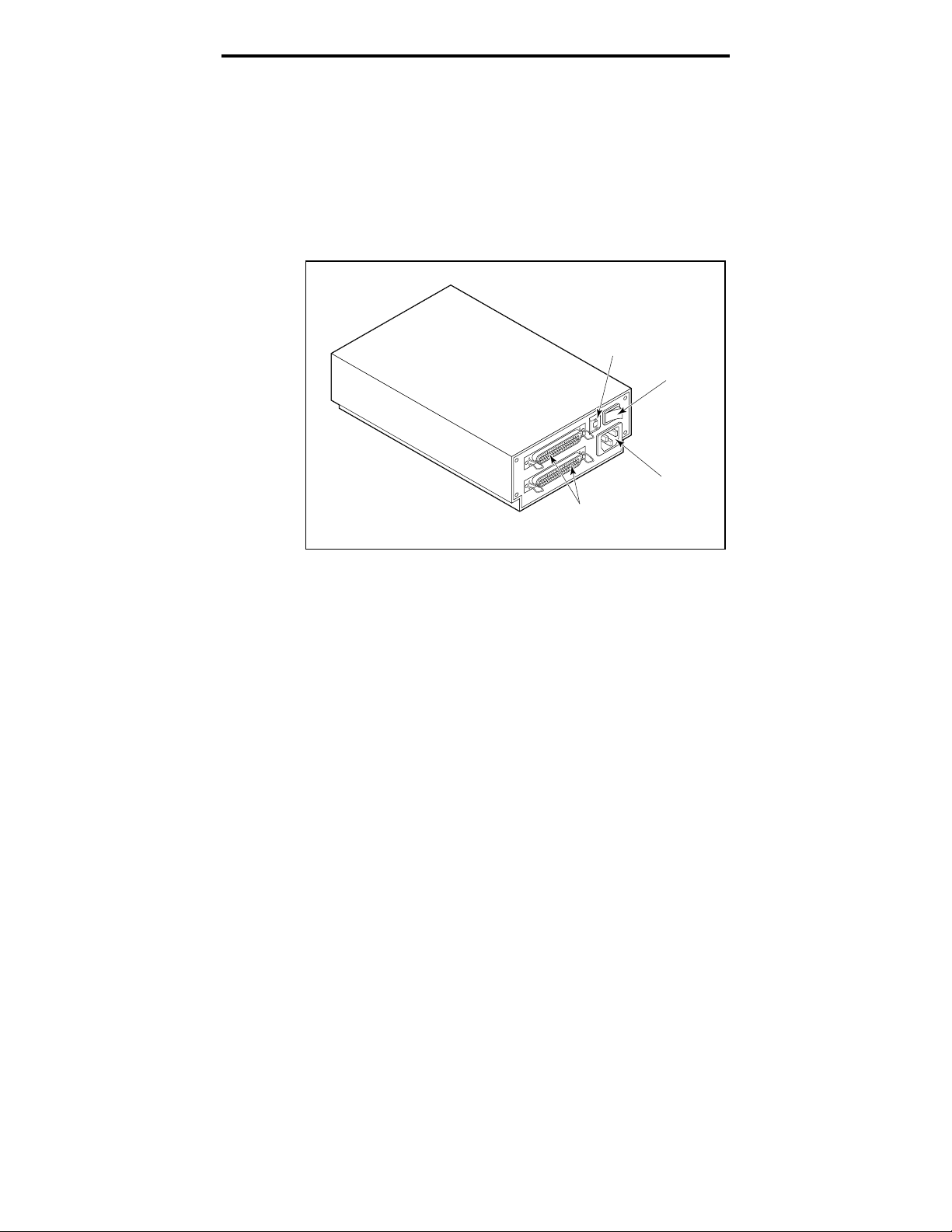
Manuel d'installation de l'unité de bande DAT Seagate 13
connecteurs d'interface SCSI, l'interrupteur et le
connecteur du cordon d'alimentation.
➤ Remarque. La nouvelle identification SCSI ne sera
reconnue qu'après redémarrage de l'unité ou
réinitialisation du bus.
Figure 7
Panneau arrière des unités DAT externes
Interrupteur
Commutateur + -
6
Connecteur
d'alimentation
Connecteurs
SCSI
Branchement du câble d'interface SCSI
Les unités DAT externes Seagate comportent deux
connecteurs SCSI autorisant une connexion en
concatenations, comme le montre la figure 7. Vous pouvez
utiliser chaque connecteur pour raccorder l'unité à un
ordinateur hôte ou à un autre périphérique SCSI.
➤ Remarque: Coupez l'alimentation avant de brancher ou
de débrancher des câbles ou des fiches de terminaison.
Si l'unité es t l a de rni ère uni t é o u la s e ul e uni t é da ns une
chaîne SC S I , vo us d eve z installe r une f i che d e t erm i na i s o n
sur le connecteur SCSI inutilisé (voir la figure 8 à la page
suivante ). V o us po uvez a che t er une fi che d e t e rm i na i s on
auprès de Seagate Express (référence Seagate 38-9-
74000000).
Page 72

Manuel d'installation de l'unité de bande DAT Seagate 14
Figure 8
Diagramme d'une chaîne SCSI avec terminaison
Périphérique
SCSI externe
(terminaison activée)
Contrôleur SCSI
(terminaison activée)
Périphérique
SCSI externe
Contrôleur SCSI
Périphérique
SCSI interne
Périphérique
SCSI interne
(terminaison activée)
Exemple 1: Terminaison
SCSI sur un système avec
périphériques SCSI internes
uniquement.
Périphérique
SCSI interne
Périphérique
SCSI interne
(terminaison activée)
Exemple 2: Terminaison
SCSI sur un système avec
périphériques SCSI internes
et externes.
Branchement du cordon d'alimentation
Branchez le cordon d'alimentation sur le connecteur
d'alimentation à l'arrière de l'unité. L'emplacement de ce
connecteur est indiqué à la figure 7 (page précédente).
Page 73

Manuel d'installation de l'unité de bande DAT Seagate 15
Utilisation et maintenance d'une unité DAT
Cette section décrit comment utiliser votre unité DAT
Seagate interne ou externe. Elle indique la signification
des divers voyants sur la face avant de l'unité. Elle précise
également comment utiliser correctement les cartouches
DAT.
Codes LED
Comme le montrent les figures 9 et 10, la face avant des
unités DAT Seagate contient deux voyants rectangulaires
(LED). Ces deux voyants fournissent des informations sur
les conditions normales et d'erreur. Le voyant jaune
rectangulaire indique la condition de l'unité de bande. Le
voyant vert indique la condition de la cartouche de bande.
➤ Remarque. Les unités DAT externes comportent
également un voyant d'alimentation vert rond sur la
face avant.
Figure 9
Face avant d'une unité DAT interne
Etat d'unité
(jaune)
Fente d'introduction de cartouche
Etat de cartouche
(vert)
Bouton d'éjection
Page 74

Manuel d'installation de l'unité de bande DAT Seagate 16
Figure 10
Face avant d'une unité DAT externe
Etat d'unité
(jaune)
Etat de
cartouche
(vert)
Cassette Insertion Slot
Alimentation
(vert)
Voyant d'état de l'unité
Le voyant d'état de l'unité est jaune et indique les
conditions suivantes:
Si le voyant d'état de l'unité est allumé en continu,
•
l'unité lit ou écrit sur la bande (ce qui signifie qu’une
activité SCSI ou DAT est en cours). Si vous appuyez
sur le bouton d'éjection alors que le voyant d'état de
l'unité est allumé, vous pouvez perdre des données.
➤ Remarque. Pendant une commande SCSI PREVENT
MEDIA REMOVAL, le voyant d'état de l'unité est
toujours allumé.
Si le voyant d'état de l'unité clignote rapidement, une
•
faute matérielle a été détectée. Si cela se produit
immédiatement après la mise sous tension et si vous
avez activé l'autotest à la mise sous tension (par un
positionnement du cavalier), l'autotest à la mise sous
tension peut échouer et l'unité ne fonctionnera pas.
Bouton d'éjection
Page 75

Manuel d'installation de l'unité de bande DAT Seagate 17
Voyant d'état de cartouche
Le voyant d'état de cartouche rectangulaire vert indique
les conditions suivantes:
Si le voyant d'état de cartouche est allumé en continu,
•
une cartouche a été introduite et fonctionne
normalement.
Si le voyant d'état de cartouche clignote lentement, la
•
cartouche de bande actuellement introduite dans
l'unité a généré un nombre significatif de reprises de
données (au-delà d'un seuil d'erreur DDS prédéfini).
Ce signal constitue uniquement un avertissement et
n'indique pas une perte de données.
Si vous voyez ce signal, retirez la bande et nettoyez les
têtes avec une cartouche de nettoyage DDS DAT
certifiée (telle que le modèle Seagate 91301). Si le
voyant continue à clignoter ou clignote lors de
l'éjection de la cartouche, utilisez une nouvelle
cartouche pour les futures opérations d’écriture.
➤ Remarque. A titre de maintenance systématique, les
têtes de l'unité doivent être nettoyées toutes les 25
heures de fonctionnement. Reportez-vous aux
informations suivantes sur la maintenance.
Si le voyant d'état de la cartouche clignote lentement
•
avec le voyant jaune, une cartouche audio préenregistrée est introduite et lue automatiquement.
Si le voyant d'état de cartouche clignote rapidement,
•
l'unité ne peut pas écrire la bande correctement (le
compte de réécritures maximal a été dépassé) et
l'opération de lecture a échoué. Nettoyez d'abord les
têtes de l'unité à l'aide d'une cartouche de nettoyage
DDS DAT agréée, telle que le modèle Seagate 91301.
Si le voyant continue à clignoter, utilisez une nouvelle
cartouche pour les futures opérations d’écriture.
Page 76

Manuel d'installation de l'unité de bande DAT Seagate 18
Récapitulatif des codes de voyant LED
Le tableau suivant récapitule les codes de clignotement de
voyant pour les unités DAT Seagate.
Voyant Action Signification
Jaune
Jaune
Vert
Vert
Vert
Vert
Voyant vert
rond (unités
externes
seulement)
Allumé L'unité lit ou écrit sur la bande.
Clignote rapidement Une faute matérielle s'est produite.
Allumé Une cartouche est introduite et ne
génère PAS un taux d'erreurs
excessif.
Clignote lentement Une cartouche est introduite mais
génère un taux d'erreurs excessif
au-delà d'un seuil d'erreur prédéfini
(avertissement seulement).
une cartouche de nettoyage DDS
pour nettoyer les têtes.
Clignote lentement
(avec le voyant jaune
clignotant)
Clignote rapidement L'unité n'a pas pu écrire la bande
Allumé L'unité externe est sous tension.
Une cartouche audio préenregistrée est introduite et lue
automatiquement.
correctement. (Erreur)
cartouche de nettoyage DDS DAT
pour nettoyer les têtes.
Utilisez
Utilisez une
Mise en place d'une cartouche
Les unités DAT Seagate comportent une baie de cartouche
à chargement frontal simplifiant leur utilisation. La porte
de l'unité s'ouvre automatiquement lors de l'introduction
d'une cartouche. La figure 11 de la page suivante montre
une cartouche introduite dans une unité interne 3,5
pouces. Une fois que vous avez introduit la cartouche, un
bref délai précède l'identification du type de cartouche et
de son état, et le positionnement de la bande dans la zone
de données.
Page 77

Manuel d'installation de l'unité de bande DAT Seagate 19
Figure 11
Chargement d'une cartouche de bande DAT (unité
3,5 pouces)
Retrait d'une cartouche
!
Attention: Ne poussez pas le bouton d'éjection
alors que le voyant d'état de l'unité est allumé.
Vous pourriez perdre des données.
Assurez-vous que le voyant d'état de l'unité n'est pas
allumé. Pour retirer la cartouche, appuyez ensuite sur le
bouton d'éjection. Pour l'emplacement du bouton
d'éjection, reportez-vous à la figure 9, page 15, ou à la
figure 10, page 16. Une fois que vous avez appuyé sur le
bouton d'éjection, l'unité vide automatiquement le tampon
de l'unité sur la bande, met à jour le journal du système et
rembobine la cartouche avant de l'éjecter.
➤ Remarque. Plusieurs secondes peuvent s'écouler
entre l'enfoncement du bouton d'éjection et l'éjection
de la cartouche. Ne mettez pas hors tension l'unité de
bande ou l'ordinateur hôte pendant cette période.
Initialisation d'une cartouche DAT vierge
Lorsque vous i nt ro dui s e z une cartouche vierge da ns l'unité l a
première fois, l'unité met de 10 à 12 secondes pour
Page 78

Manuel d'installation de l'unité de bande DAT Seagate 20
déterminer si la bande est vierge. L'unité initialise
automatiquement la bande à la réception d'une commande
d’écriture de pui s l 'o rdi na t eur hô t e. L 'i nit i a l i s a t i on d 'une
bande vierge met dure 30 secondes. Des opérations d'écriture
sont exécutées pendant l'opération d'initialisation sans
retard, jusqu'au remplissage de tous les tampons internes.
➤ Remarque. L'éjection de la cartouche avant la fin de
l'initialisation entraîne l'abandon de la procédure.
L'initialisation redémarrera à zéro dès réception de la
prochaine commande WRITE.
➤ Remarque. Le tampon de données de l'unité est vidé
sur la bande si une commande REWIND est émise, si
le bouton d'éjection est enfoncé, ou si un retard dans
l'activité SCSI se produit. Par défaut, le retard avant
le vidage a une valeur d'une minute. Cependant, ce
retard peut être modifié par l'application hôte à l'aide
d'une commande MODE SELECT.
Compatibilité des cartouches DAT
Les unités DAT Seagate ont été conçues pour utiliser des
cartouches de données DDS DAT conformes aux
spécifications ANSI indiquées dans le document “ 3.81 mm
Helical-Scan Digital Computer Tape Cartridge for
Information Interchange ”, norme ANSI X3B5/89-156.
Pour assurer une intégrité et une fiabilité optimales, nous
vous conseillons d'utiliser les cartouches DDS DAT
Seagate suivantes:
Modèle M31300 (60 mètres)
•
Modèle M32000 (90 mètres)
•
Modèle M34000 (120 mètres)
•
Modèle M312000 (125 mètres ; DDS-3 seulement)
•
Les unités DAT DDS-2 et DDS-3 reconnaissent également
les cartouches 120 mètres MP+ et les autres cartouches
MRS lorsque le mode MRS est activé. Les cartouches MRS
Page 79

Manuel d'installation de l'unité de bande DAT Seagate 21
comportent une série alternée de bandes claires-obscures
au début de la bande. Ces bandes catégorisent le support
au niveau données, et non au niveau audio. Quatre trous
de reconnaissance permettent à l'unité d'identifier le type
de bande, de déterminer son épaisseur magnétique, puis
de déterminer si la bande est pré-enregistrée, ou non
enregistrée, ou encore s'il s'agit d'une cartouche de
nettoyage. D'autres fonctionnalités permettent à la bande
de détecter de façon optique les états “ cartouche
introduite ”, début de bande et fin de bande.
➤ Remarque. Le voyant vert clignotant lentement avec
le voyant jaune indique qu'une bande audio préenregistrée a été introduite dans l'unité.
Protection en écriture d'une cartouche DAT
La figure 12 indique comment protéger en écriture ou
activer l'écriture d'une bande DAT à l'aide de l'onglet
curseur de protection en écriture. Vous pouvez
uniquement écrire des données sur la bande lorsque
l'onglet se trouve en position fermée.
Figure 12
Onglet de protection contre l'écriture sur la
cartouche DAT
Nettoyage des têtes
Si de la poussière magnétique ou des débris s'accumulent
sur l'une des têtes, votre unité peut ne plus être en
mesure de lire ou d'écrire sur la bande. Pour éviter cet
Écriture
autorisée
Écriture
interdite
Page 80

Manuel d'installation de l'unité de bande DAT Seagate 22
incident, il convient de nettoyer les têtes de l'unité DAT
dans les circonstances suivantes:
Après les quatre premières heures de déplacement
•
d'une nouvelle cartouche,
Toutes les 25 heures de lecture/écriture, et
•
Lorsque le voyant d'état de cartouche vert clignote en
•
cours de fonctionnement.
➤ Remarque. Un voyant vert clignotant lentement peut
indiquer qu'une bande est endommagée ou usagée. Si
le nettoyage de la tête n'arrête pas le clignotement du
voyant, remplacez la cartouche. Un clignotement lent
n'indique ni une perte de données, ni des problèmes
SCSI.
Pour nettoyer les têtes de l'unité DAT, utilisez
uniquement une cartouche de nettoyage DDS DAT
certifiée par Seagate et conçue exclusivement pour les
unités DAT. Seagate propose une cartouche de nettoyage,
modèle 91301, que vous pouvez commander à Seagate
Express (cinq par lot).
Une fois que vous avez introduit la cartouche de nettoyage,
l'unité reco nna î t ce t yp e de ca rt ou che, p ui s cha rge et e xécut e
la carto uche pe nd a nt envi ro n 3 0 s e cond es. Une fois l e
nettoya ge t e rm i né, l 'uni t é éjecte la cartouche.
➤ Remarque. A chaque cha rge m ent d e la cartouche de
nettoyage, une nouvelle partie inutilisée de la bande de
nettoya ge a va nce s ur t o ut e l a l o ngueur d u ci rcui t b a nd e.
L'unité ne rembobine p a s une ca rt o uche d e net t o ya ge.
Après environ 30 cycles de nettoyage, toute la bande a été
utilisée et vous devez en acheter une nouvelle.
Si vous introduisez une cartouche de nettoyage usée,
l'unité l'éjecte sans exécuter l'opération de nettoyage.
Ce processus s'effectue en moins de 25 secondes.
➤ Remarque. N'utilisez pas de cartouche de nettoyage
DAT audio. L'unité ne la reconnaîtra pas.
Page 81

Manuel d'installation de l'unité de bande DAT Seagate 23
Support technique
Si vous rencontrez des problèmes lors de l'installation ou de
l'emploi de l'unité DAT, contactez l'un des services de support
technique indiqués ci-dessous.
SeaFONE:
1-800-SEAGATE (1-800-732-4283)
Les clients internationaux doivent appeler le 408-456-4496.
SeaNET:
Forum CompuServe Seagate
Page d'accueil Web de Seagate—
: Support technique en ligne pour produits
Seagate sur CompuServe. Tapez
SeaBOARD:
Système BBS automatisé de Seagate, disponible 24 heures sur
24. Réglez votre modem sur 9 600 bauds, 8 bits de données, pas
de parité et un bit d'arrêt (8-N-1).
Australie 61-2-9756-2359 Angleterre 44-1628-478011
France 33 1-48 25 35 95 Allemagne 49-89-140-9331
Taïwan 886-2-719-6075 Singapour 65-292-6973
Thaïlande 662-531-8111 Etats-Unis 408-456-4415
SeaFAX:
Vous pouvez utiliser un téléphone à touches pour accéder au
système de télécopie automatisé de Seagate pour recevoir des
informations de support technique par retour de télécopie. Ce
service est disponible 24 heures sur 24.
Australie 61-2-9756-5170 Angleterre 44-1628-894084
Etats-Unis 1-800-SEAGATE ou 408-456-4496
Fax de support technique Seagate
ou des commentaires aux spécialistes du support technique 24
heures sur 24. Les réponses sont envoyées durant les heures
ouvrables.
Australie 61-2-9725-4052 Angleterre 44-1628-890660
France 33 1-46 04 42 50 Allemagne 49-89-1430-5100
Hong Kong 852-2368 7173 Japon 81-3-5462-2979
Corée 82-2-556-7294 Singapour 65-488-7528
Taïwan 886-2-715-2923 Etats-Unis 408-944-9120
http://www.seagate.com
go seagate
.
: Vous pouvez télécopier des questions
Support technique par e-mail Seagate:
des questions ou des commentaires à l'adresse suivante:
tapesupport@seagate.com
Support technique Seagate:
Pour une question technique isolée, vous
pouvez demander l'assistance d'un spécialiste du support
technique pendant les heures ouvrées.
Australie 61-2-9725-3366 Angleterre 44-1628-894083
France 33 1-41 86 10 86 Allemagne 49-89-140-9333
Hong Kong 852-2368 9918 Corée 82-2-556-8241
Vous pouvez envoyer par e-mail
Page 82

Manuel d'installation de l'unité de bande DAT Seagate 24
Singapour 65-488-7584 Taïwan 886-2-514-2237
Etats-Unis 1-800-SEAGATE or 408-456-4496
SeaTDD:
Support technique pour utilisateur d'un dispositif de
télécommunication pour les mal-entendants (TDD): 408-9449121
 Loading...