

Seagate Cheetah 73,ST173404LW,ST173404LC,ST173404LWV,ST173404LCV Installation Manual
Cheetah 73 Installation Guide
Model ST173404LW/LC/LW V/LCV, SCSI interface disc drive
Publi cation Number: 83329479, Rev. A, December 1999
Handling precautions/electrostatic discharge pr otection
• Disc drive s are fragi le. Do not dr op or jar the drive and handle the drive
only by the edges or frame.
• Drive electronics are extremely sensitive to static electricity. Keep the
drive in its antistatic container until you are ready to install it. Wear a wr ist
strap and cable connected to gr ound. Di scharge stati c from all items near
or that will contact the drive. Never use an ohmmeter on any circuit
boards.
• Turn off the power to the host system during installation.
• Always use forced-air ventilation when operating the drive.
• Use caution when troubleshooting a unit that has voltages present.
• Do not disassemble the drive; doing so voids the warranty.
• Return the entire drive for depot service if any part is defect ive.
• Do not apply pressure or attach labels to circuit board or drive top.
Electromagnetic compliance
See Safety and Regulatory Agency Specifications, p/n 75789512.
Driv e char ac teris tics
Formatted capa c ity .. .... .... ..........................73.4 Gbytes
Max. data blocks .......................................143,374,738 (088BB992h)
Cylinders and heads (user accessible) ......14,100 / 24 heads
Disc rotation...............................................10,033 rpm
Operating voltages .....................................+5V +12V
Typical operating current.........................0.87A 1.5A
What you need
• Phillips screwdriver and four 6-32 UNC drive mounting screws
• F orced-air ve ntilation to pr ovid e adequa te drive cooling
• An unused drive power connector (not appl icable to LC/LCV models)
To operate at LVD transfer rates, you may also need an LVD-capable SCSI
host ad apter, LVD I/O cable and active ne gation external terminator
Multimode interface
This drive can operate in single-ended (SE) or lo w voltage differential (LVD)
mode. Thi s multimod e capability pr ovides backw ards compat ibility so you
can use it with or without an LVD-capable host adapter. The primary benefits of LVD technology include faster transfer rates, reduced power consumption, increased allowable cable lengths, and improved device
connectivity.
You can configure the drive to switch between SE and LVD modes automatically or force it to operat e in SE mode only. To configure this option, see
Figure 2.
Note.
To operat e at the Ultra 2 ra te s in LVD mode, a ll devi ce s on the s a me
bus (cable) must be running in LVD mode. If you add any SE device
to the bus, all devices on that bus operate in SE mode.
Note.
Some LVD host adapte rs p r ov ide an LVD connector and an SE connector o n the same ho st adapter to allow you to run SE and LVD
drives concurrently at their maximum capabilities. Check your SCSI
host ad apter documenta tion. See Figure 3.
Caution.
Do not mix LVD drives on the same bus with high voltage differential (HVD) devices–d rive damage may o ccur.
Installation instructions
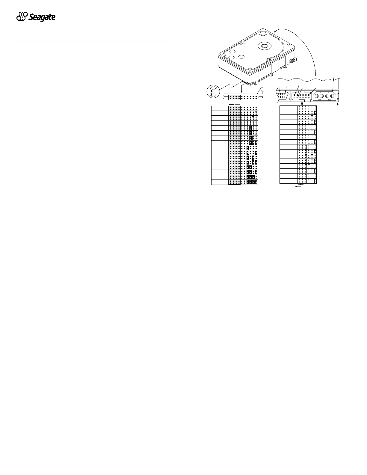
1. Set the SCSI ID
Determine which SCSI IDs are already being used in the system and then
assign this disc drive a SCSI ID that isn’t already being used. Use the J6
connector located on the front of the drive to set the SCSI ID (see Figure 1).
• Most ST173404 drives are factory set with the SCSI ID set at 0. If this is
the only SCSI d ri ve in your s yste m and the re ar e no ot her S CSI dev ices
on the daisychain, you can leave this drive’s SCSI ID set to 0 and proceed to the next step.
• The host system’s SCSI controller usually uses SCSI ID 7.
• If you have an L C or LCV mode l dr ive, t h e h os t no r m ally set s th e ID over
the I/O interface, so you don’t need to worry about this step.
• Some s ystems provid e a cable desi gned to con nect to the J5 jumpe r
block on the driv e to remotely set the ID. You can connect this cable to J5
and use the host-provided remote switch to set the SCSI ID.
Figure 1. Setting the SCSI ID
2. Configure termination
If you are installing the drive in a system that has other SCSI devices
installed, terminate only the end devices on the SCSI bus (cable). This drive
does not have internal terminators or any other way of adding internal termination on the drive. You must provide external termination when termination
is required. This is normally done by adding an inline terminator on the end
of the cable. See Figure 3 for an illustration showing a system configuration
that uses an extern a l ter m in ato r.
• Use active (ANSI SCSI-2 Alternative 2) single-ended terminators when
terminating a bus operating in single-ended mode.
• Use SPI- 2-c omp liant active low volt age di ffere nti al ter min at ors w hen te rminating a SCSI Ultra2 bus operating in LVD mode.
• The host adapter is normally on the end of the bus and internally terminated. You can configure your bus with another device on the end if you
remove termination from the host adap ter.
3. Configure t e rmina tor power
Ter minators have to get power from some source. The default configuration
results in the drive not supplying termination power to the bus. You should
normally leave this drive set at this default un less yo ur host system requires
the drive to sup ply ter minati on power to the bus. To config ure this drive to
supply termination power to the bus, place a jumper on J2 pins 1 and 2 as
shown in Figure 2.
• Host systems designed to use LC and LCV drives normally provide termination powe r fro m th e ho st adap ter or o the r so urce. For thi s reas on, L C
and LCV model drives cannot be configured to provide termination power
to the bus.
SCSI ID = 0 (default)
Jumper Plug
(enlarged to
show detail)
J6
Drive
Front
Pin 1
Reserved
A2A1A0A
L
E
D
R
E
S
3
SCSI ID = 1
SCSI ID = 2
SCSI ID = 3
SCSI ID = 4
SCSI ID = 5
SCSI ID = 6
SCSI ID = 7
SCSI ID = 8
SCSI ID = 9
SCSI ID = 10
SCSI ID = 11
SCSI ID = 12
SCSI ID = 13
SCSI ID = 14
SCSI ID = 15
J1
DC Power
J1
68 Pin
SCSI I/O
Connector
Drive HDA
Rear
SCSI ID = 8
SCSI ID = 9
SCSI ID = 10
SCSI ID = 11
SCSI ID = 12
SCSI ID = 13
SCSI ID = 14
SCSI ID = 15
A
not used
3A2A1
SCSI ID = 0
SCSI ID = 1
SCSI ID = 2
SCSI ID = 3
SCSI ID = 4
SCSI ID = 5
SCSI ID = 6
SCSI ID = 7
A
0
J5
Pin 1
4P 3P 2P 1P
PCBA
Pin 1
+5V
Ground
(default)
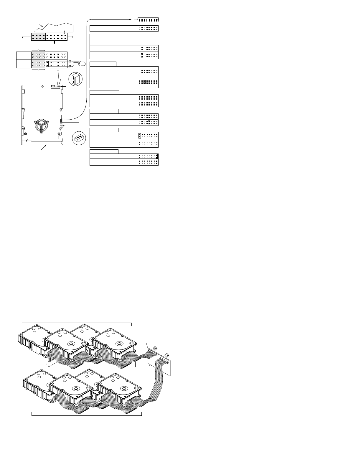
Figure 2. Option select jumpers
4. Connect the drive activity LED (optional)
Connect the Drive Activity LED cable to J6 pins 11 and 12 (see Figure 2), or
conne ct a drive ID and Dr ive Activit y LED cable to J5, de pending on host
system requirements.
5. Check the other available jumper settings
Select other options on J2 as illustrated in Figure 2. Do not change these
unless instructed to do so by the host system documentation.
6. Mount the drive in the host system and connect cables
Note.
LC and LCV drives are designed to be attached to a carrier or
tray and in ser ted into t he host system without I /O or pow er
cables.
a. Mount LW and LWV model drives to the host system’s chassis
using four 6-32 UNC screws. Two mounting holes are in each side
of the dr ive and t her e are fou r m ounti ng ho les in t he bo ttom of t he
drive. Do not over-tighte n or force th e screws. You can mount the
driv e in any orientation.
b. Connect th e SCSI I/O cable in to the drive’s SCSI connector. Take
care not to stretch or crimp this cable, and do not block the system’s
cooling air flow with the cable.
Note.
For Ultra2 and faster operation, special twisted pair LVD
cables are
required
.
c. Connect the DC power cable to the driv e. See Fi gure 3.
Figure 3. Cable connections and external termination
7. Format the drive
The drive has been
low level
formatt ed at the fact ory. You do not need to
perform another low level format on this drive unless you decide to perform
cert ai n diag nos tics thr ough the hos t adap te r. If you do dec ide to pe rfor m a
low level format, d o not abor t the format as thi s is likely to make the dr ive
inoperable. A low l evel format, with ver ify tur ned on, wi ll typical ly take four
hours.
Protect against power failure or other power interrup tions during the format.
a. Turn on DC power to the host system.
b. Boot t he system from a system flo ppy, CD, or from a previously
insta lled hard disc dri ve if there is one.
c. Format the drive.
Caution.
Formatt ing a dr ive eras es all user data. B e sure tha t you un derstand t his pr in ci ple before fo r ma t ti ng any ha rd d is c drive. It is not
necessary to format a drive that previously has been used to
store data, unless your intention is to erase all user data. Seagate
is not responsible for lost user data.
Cheetah disc drives are desi gned to operate with a variety of oper ating systems. Pl e as e refer to your sy st em or SC SI contro ller man ua l for info r m at i on
about formatting and setting up the drive. Some quick desktop system notes
are provided below.
•
Microsoft
TM
.
Set the drive typ e in CMOS to “
Zero,” “None,”
or “
No hard
drive installed
.” Use FDISK.EXE and FOR MAT.EX E. Sy stem s using Win-
dows 98 or later can create one single partition (drive letter) on the drive.
•
Macintosh
TM
.
Use a third-party drive utility (most revisions of Apple’s HD
Setup utility only work with drives having special Apple firmware).
Troubleshooting
•
Drive does not spin up.
Check cables and all jumper settings. Make
sure cable pin 1 (edge st ripe) matc hes PCB pin 1.
•
Drive spins, but no LED on/off activity.
Check SCSI ID setting. Set the
ID so that each device on the SCSI chain has its own unique ID. See also
the next item below. Host I/O controller is usually ID7.
•
Computer does not seem to recognize the drive.
Verify that the d rive
is enabled by the SCSI host adapter setup utility.
•
FDISK do es not det ect the dri ve.
Run the FDISK program located on
your Windows startup diskette. Type fdisk/status to verify that your hard
driv e is present.
Seagate support services
For online information about Seagate products, visit www.seagate.com or email your disc questions to DiscSupport@Seagate.com
If you nee d he lp insta lling yo ur dri ve, con sult your deal er firs t. If you need
additio nal help, ca ll a Seagat e technica l suppor t specia list. Befo re calling ,
note your system configuration and drive model number (
ST173404LW/
LWV or ST173404LC/LCV) .
Africa +31-20-316-7222 Poland 00 800-311 12 38
Australia +61-2-9725-3366 Spain 900-98 31 24
Aus tria 0 800-20 12 90 Sweden 0 207 90 073
Belgium 0 800-74 876 Switzerland 0 800-83 84 11
Denmark 80 88 12 66 Singapore +65-488-7584
France 0 800-90 90 52 Taiwan +886-2-2514-2237
Germany 0 800-182 6831 T urkey 00 800-31 92 91 40
Hong Kong +852-2368 9918 United Kingdom 0 800-783 5177
Ireland 1 800-55 21 22 USA/ Canada/ 1-800 SEAGATE or
Italy 800-790695 Latin America +1-405-936-1234
Middle East +31-20-316-7222 Other European
Nether lands0 800-732-42 83 countries +31-20-316- 7222
Norway 800-113 91
Warranty.
Contact your place of purchase or our web site (above).
Return Merchandise Authorization (RMA).
Before returning t he d r ive, verify th at i t
is defective. Seagate Worldwide customer service centers are the only facilities authorized to service Seagate drives. Contact nearest center for return procedures and trade
regulations.
Shipping the drive
Caution.
Back up the data before shipping. Seagate assumes no respons ibility for
data lost during s hipping or serv ice. Shipping dr ive in an una pproved container voids
the warranty. Pack the drive with ori ginal box and packing materials. Use no o ther
materials. This prevents electrical and physical damage in transit.
© 1999 Seagate Technology, Inc. All rights reserved
Publication number: 83329479, Rev. A, December 1999, Printed in U.S.A.
Seagate, Seagate Technology, the Seagate Logo, and Cheetah a re either regist ered
trademarks or tra demarks of Seagate Technology, Inc. All other trademarks are the
property of their respective owners.
Enable parity check of SCSI bus.
Disable parity check.
J2
Pin 1
Reserved Positions
Parity Check option
Single-ended I/O
Terminator Power
Write protect = Off (enables writing).
Write protect = On (disables writing).
Write Protect option
Disable the Delay Motor Start option.
Motor start delay equal to the
SCSI ID multiplied by 12 seconds.
Delay Motor Start option (valid
only if the Enable Motor Start
jumper is not connected)
Enable motor start. The drive waits for
the Start Unit command from the host
before starting the spindle motor.
Disable motor start (default). The
drive starts according to the Delay
Motor Start option.
Motor Start option
Pin 1
End
SCSI I/O
Connector
Drive with
HDA up, PCB
down, viewed
from front
Pin 1
DC Power
Connector
J2
Drive Front
J6
J1
Pin 1
HDA
J6
A2A3A1A
0
Reserved
Remote
LED
L
E
D
R
E
S
Reserved
Shipped with cover installed.
Do not remove.
Do not install jumpers
on these four positions.
J6 Jumper
CATH
11
12
J2 Jumper
(default)
(default)
(default)
(default)
A jumper here forces single-ended
I/O operation.
No jumper allows host to select either
single-ended or LVD operation.
Host adapter or other device provides
term. power to external terminator.
Term. Power to SCSI Bus
(default)
(default)
Pin 1
(check your
adapter for
Pin 1 location)
Host
Adapter
PCB
Twisted Pair
LVD Cable
Ultra160 or Ultra2 LVD bus segment
SPI-2 compliant
active LVD
external terminator
on the end of
the cable
SCSI LVD/SE
SCSI SE
Ultra SCSI SE bus segment
 Loading...