

Seagate Cheetah 36LP FC,ST336704FC,ST336704FCV,ST318304FC,ST318304FCV Installation Manual
Cheetah 36LP FC Installation Guide
Models ST336704FC/FCV and ST318304FC/FCV
Fibre Channel interface disc drive
Publi cation Number: 83329481, Rev. B, November 2000
Handling precautions/Electrostatic discharge protection
• Disc drive s are fragi le. Do not dr op or jar the drive and handle the drive
only by the edg es or frame.
• Drive electronics are extremely sensitive to static electricity. Keep the
drive in its antistatic container until you ar e ready t o install it. Wear a wrist
strap and cable connected to ground. Discharge static from all items near
or that will contact the drive. Never use an ohmmeter on any circuit
boards.
• Turn off the power to the host system during instal lation.
• Always use forced-air ventilation when operating the drive.
• Use caution when troubleshooting a unit that has voltages present.
• Do not disassemble the drive; doing so voids the warranty.
• Return the entire drive for depot service if any part is def ective.
• Do not apply pressure or attach labels to circuit board or drive top.
Electromagnetic compliance
See Safety and Regulatory Agency Specifications, p/n 75789512.
Driv e char ac teris tics
ST336704 ST318304
Formatted capacity 36.7 Gbytes 18.35 Gbytes
Max. data blocks 71,687,369 35,964,301
(0445DCC8h) (0224C58Ch)
Cylinders and heads (user accessible) 14,100/12 heads 14,100/6 heads
Disc rotation 10,033 rpm 10,033 rpm
Operating v oltages +5V +12V +5V +12V
Typical operating cu rrent 0.93A 1.14A 0.93A 0.91A
What you need
• Phillips screwdriver and four 6-32 UNC drive mounting screws
• F orced-air ventilation to provide adequate drive cooling
• Host system with Fibre Channel host adapter or backplane
Installation instructions
1. Mount the drive in the host system carrier or tray
Most Fibre Channel host systems (including enclosures) provide a way to
insert the drive using a carrier or tray which allows the drive to be hotplugge d into the sys tem’s Fibre Cha nnel 40-pin single connector attachment (FC-SCA).
Mount th e drive to the carrier or tr ay prov ided by th e ho st system usi ng four
6-32 UNC screws. Two mounting holes are in each side of the drive and
there are four mounting holes in the bottom of the drive. Do not over-tighten
or force the screws. You can mount the drive in any orientation. See Figure
Figure 1.
Note.
FC and FCV d rives are desi gned to be att ache d t o the h ost s yst em
without I/O or power cables.
Figure 1. Sample drive carrier
Note.
Figure 1 above shows a generic carrier. Most carriers will look dif ferent than the o ne shown. Many are actu ally sm all enc losur es rath er
than brackets as shown here.
2. Insert the drive
Slide th e ca rrier or tray in to th e approp riat e bay in yo ur ho st sys tem. T his
connects the drive directly to your system’s 40-pin Fibre Channel single
connector attachment (FC-SCA). The FC-SCA connector is normally
located on a Fibre Channel back panel.
Note.
There ar e no ju mpers o r t er m inators o n t h e d rive, and p ower is s up plied through the 40-pin connector.
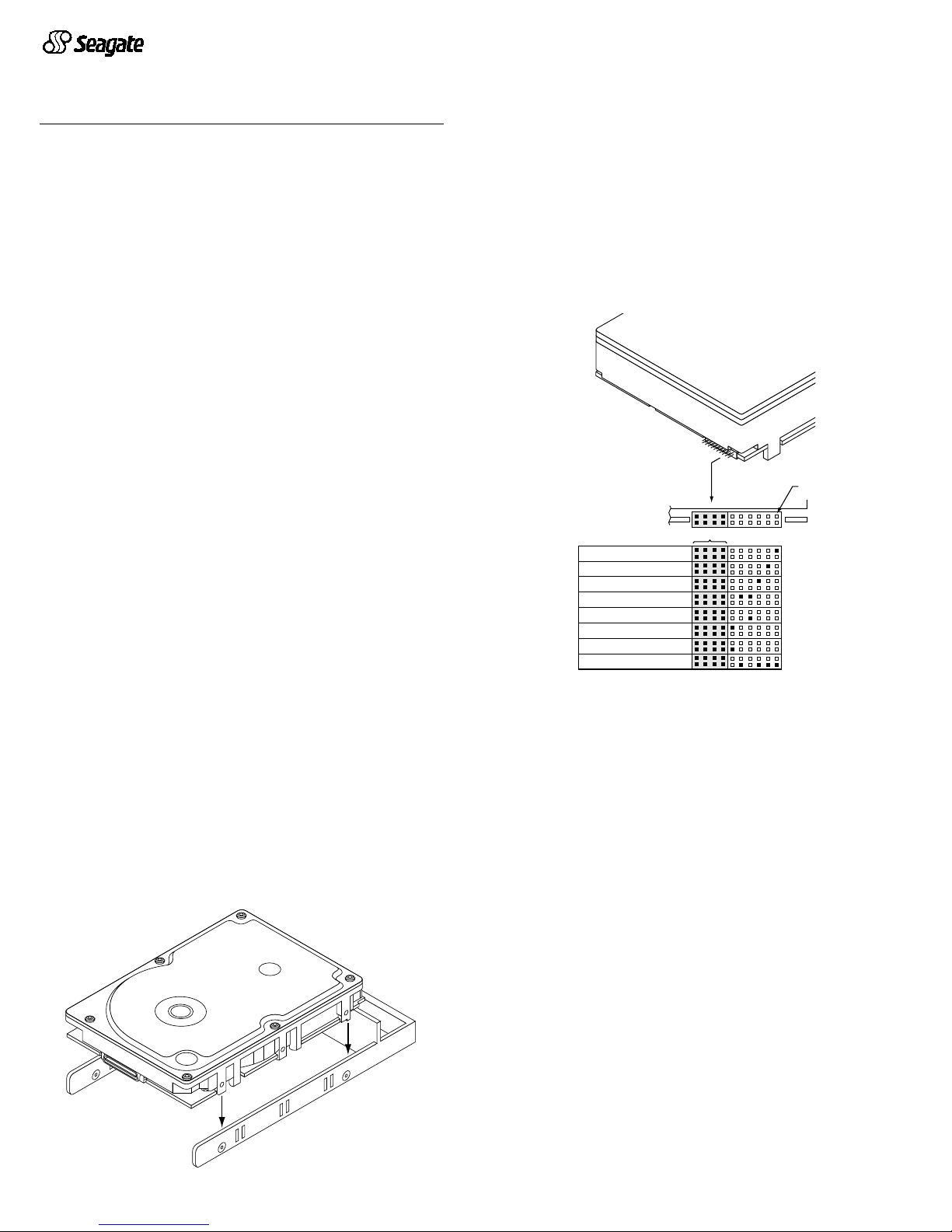
3. Connect LEDs (optional)
Note.
This is an opti onal step. T he dri ve will wor k fine without the LEDs
connected to the drive.
The drive supplies pins that you can use to connect fault and active LEDs.
This allows you to monitor drive fault conditions and activity. The actual
LED is external to the drive.
[1] The drive ha s a 2.2K oh m re si st or in series with this LED driver. Tie the
minus side of an external high-efficiency LED (i.e., 2ma) to this pin.
Connect the plu s side of the LED to +5 V.
[2] An external current-limiting resistor is required when connecting an
LED to th is pin. Th e m inu s s ide of th e resist or /LED combinat io n is c on nected to this pin. Connect the plus side to +5V.
[3] Jumper stora ge location (across pins 2 an d 4).
Figure 2. LED indicator connector
Fault LED Signal
The drive activates the fault LED Out signal when:
• the drive det ects failure of both ports
• the drive det ects an internal failure
• the drive receives the appropriate fault LE D command from the host
Active LED signal
The drive activates the active LED signal as indicated below.
Normal command activity LED status
Spun down and no activity ............. Slow blink (20% on and 80% off)
Spun down and activity .................. On
(comm an d execu tin g)
Spun up and no activity.................. On
Spun up and activity ....................... Off
(comm an d execu tin g)
Spinning up or down....................... Blinks steadily (50% on and 50% off)
Format in progre ss ........ .... ............. Toggles on/off
(each cy li nder chan ge )
J6
Drive
Front
Pin 1
Port A Bypass LED [1]
Reserved
Port B Bypass LED [1]
Fault LED [1]
Reserved
Active LED [2]
+5V
Active LED [1]
Ground [3]

4. Format the drive
The drive has been low level formatte d at the factor y. You do not n eed to
perform another low level format on this drive unless you decide to perform
cert ai n diag nos tics thr ough the hos t adap te r. If you do dec ide to pe rfor m a
low level format, d o not abo rt the format as thi s is likely to make the dr ive
inoperable. A low level format, with veri fy turn ed on, will typ ically ta ke two
hours.
Protect against power failure or other power interruptions during the format.
a. Turn on DC power to the host system.
b. Boot the system from a system floppy, CD, or from a previously
insta lled hard disc drive if there is one.
c. Format the dri ve.
Caution.
Formatt ing a dr ive eras es all us er data. B e sure tha t you un derstand this principle before formatting any hard disc drive. It is not
necessary to format a drive that previously has been used to
store data, unless your intention is to erase all user data. S eagate
is not responsible for lost user data.
Cheetah disc dr ives are design ed to oper ate with a variety of operating systems. Please refer to your system or Fibre Channel host adapter (controller)
manual for information about formatting and setting up the drive for use with
your particul ar op er a tin g sy s t em .
Hot plugging the drive
This drive features hot plugging capabilities which allows you to insert and
remove the drive without powering down the host system. Any time a drive
is inser te d or removed from a F ibre Chan nel lo op, a sho r t loop inter ru ption
occurs and the loop resynchronizes automatically to accommodate the
added (or rem oved ) dri ve.
Drive startup options
The drive’s motor will sta rt spin ni ng the dis cs ba se d on the st atus of t wo si gnals set by the host adapter. These two signals are called Start_1 and
Start_2 . There are four options as describ ed below.
Option Start_2 Start_1 Motor spin function
1........... Low .......Low ........ Motor spins up at DC power on.
2 . .......... High ...... Low . ....... Motor spi ns up when the host adapter sen ds
the SCSI Start command.
3 ........... Low ....... High........ Motor spins up after a delay of 12 seconds
times the physical address of the drive.
4........... High ...... High........The drive will not spin up.
Most systems that host only a couple of drives use option 1 to enable all of
the drives to st art up im mediat el y w h en pow er i s applied to the d r i ves. Sy s tems h osti ng la rge r nu mbe rs of dr ives may be con fig ured to start d rives at
various times to avoid overloading the capabilities of the host system’s
power supply.
If you want to change the startup option for the drive, please refer to the
docum enta tio n prov ided wit h yo ur Fib re C ha nnel host ad apte r or ho st sy stem.
Troubleshooting
•
Drive d oes not spi n up.
Remove and then reinsert the drive into the
drive bay on t h e h os t- s u pplied carrier or tr ay. Make sure t h e d r i ve m a kes
firm contact with the host’s FC backpanel connector. Also, check the
drive sta rt up opt ions for t he Star t_1 and S tar t_2 sig nals co ntrol led fr om
your host adapter. See “Drive Startup Options” above for the four possible startup options.
•
Computer does not seem to recognize the drive.
Verify that th e drive
is enabled b y the FC host adapter setup utility.
Seagate support services
For online inf ormation about Seagate products, visit www.seagate.com or email your disc questions to DiscSupport@Seagate.com
If you nee d he lp insta lling yo ur dri ve, con sult your deal er firs t. If you need
additio nal help, ca ll a Seagat e technica l suppor t specia list. Befo re calling ,
note your system configuration and drive model number (ST336704 or
ST318304).
Africa +31-20-316-7222 Norway 800-113 91
Australia 1800-14-7201 Poland 00 800-311 12 38
Austria 0 800-20 12 90 Spain 900-9 8 31 24
Belgium 0 800-74 876 Sweden 0 207 90 073
Denmark 80 88 12 6 6 Switzerland 0 800-83 84 11
France 0 800-90 90 52 Singapore 800-1101-150
Germany 0 800-182 6831 Taiwan +886-2-2514-2237
Hong Kong 800-90-0474 Thailand 001-800-11-0032165
Indone si a 001-80 3- 1 -003-21 65 Turkey 0 0 800-31 92 91 40
Ireland 1 800-55 21 22 United Kingdom 0 800-783 5177
Italy 800-790695 USA/Canada/ 1-800 SEAGATE or
Malaysia 1-800-80-2335 Latin America +1-405-936-1234
Middle East +31-20-316-7222 Other European
Netherlands 0 800-732-4283 countries +31-20-316-7222
New Zealand 0800-443988
Warranty.
Contact your place of purchase or our web site (above).
Return Merchandise Authorization (RMA).
Before returning t he d r ive, verify th at i t
is defective. Seagate Worldwide customer service centers are the only facilities authorized to service Seagate drives. Contact nearest center for return procedures and trade
regulations.
Shipping the drive
Caution.
Back up the data before shipping. Seagate assumes no respons ibility for
data lost during s hipping or serv ice. Shipping dr ive in an una pproved container voids
the warranty. Pack the drive with or iginal box and packing materials. Use no o ther
materials. This prevents electrical and physical damage in transit.
© 2000 Seagate Technology LLC. All rights reserved
Publication number: 83329481, Rev. B, November 2000, Printed in U.S.A.
Seagate, Seagate Technology, the Seagate Logo, and Che etah are either regist ered
trademarks or tr ademarks of S eagate Technology LLC. All other trade marks are th e
property of their respective owners.
 Loading...