

Seagate Cheetah 18XL,ST318404LW,ST318404LC,ST39204LW,ST39204LC Installation Manual
Cheetah 18XL Installation Guide
Model ST318404LW/LC and ST39204LW/LC SCSI i nterface disc dr ive
Publication Number:
75789507
, Rev. B, August 2000
Handling precautions/Electrostatic discharge pr otection
• Disc dr ives ar e frag ile. Do not drop o r jar the dr ive an d hand le the drive
only by the edg es or frame.
• Drive electronics are extremely sensitive to static electricity. Keep the drive
in its an tis tatic con t ai ne r un til you are read y to install it. Wear a wr is t s t rap
and cab le co nn ect e d to gr oun d. Disc ha rge st a ti c fro m al l i tems ne ar or t hat
will contact the drive. Never use an ohmmeter on any circuit boards.
• Turn off the power to the host system during installation.
• Always use forced-air ventilation when operating the drive.
• Use caution when troubleshooting a unit that has voltages present.
• Do not disassemble the drive; doing so voids the warranty.
• Return the entire drive for depot service if an y part is def ective.
• Do not apply pressure or attach labels to circuit board or drive top.
Electromagnetic compliance
See Safety and Regulatory Agency Specifications, p/n 75789512.
Driv e character istic s
ST318404 ST39204
Formatted capacity ...................................... 18.352 Gbytes 9.176 Gbytes
Max. data blocks .......................................... 35,843,670 17,921,835
(222EE56h) (111772Bh)
Cylinders/heads (user accessible)................ 14,100/6 14,100/3
Disc rotation.................................................. 10,000 rpm 10,000 rpm
Operating v oltages +5V +12V +5V +12V
Typical operating current............................ 1.00 0.95 0.80 0.75
What you need
• Phillips screwdriver and four 6-32 UNC drive mounting screws
• F orced-air ventilation to provide adequate drive c ooling
• An unused dri ve power connector (not applicable to LC models)
To operate at LVD transfer rates, you may also need an LVD-capable SCSI
host ad apter, LVD I/O cable and active negation exte rnal terminator.
Multimode interface
This dr ive can oper ate i n sing le- end ed (S E) or l ow volt age di ffere ntial (LVD)
mode. This multimode capability provides backwards compatibility so you
can use it with or without an LVD-capable host adapter. The primary benefits
of LVD technology include faster transfer rates, reduced po wer consumption,
increased allowable cable lengt hs, and improv ed device connectivity.
You can configure the drive to switch between SE and LVD modes automatically or force it to operate in SE mode only. To configure this option, see Figure 2.
Note.
To operate at the Ultra2 rates in LVD mode, all devices on the same
bus (cable) must be running in LVD mode. If you add any SE device to
the bus, all devices on that bus operate in SE mode.
Note.
Some LVD host adap te rs prov ide an LVD connect or and an SE con-
nector o n the same ho st adapter to al low you to run SE and LVD
drives c oncurre ntly at their ma ximum ca pabilitie s. Check you r SCSI
host ad apter documentation. See Figure 3.
Caution.
Do not mi x LVD drives on the same bus w ith high volt a ge di f ferential (HVD) de vices–drive damage may occur.
Installation instructions
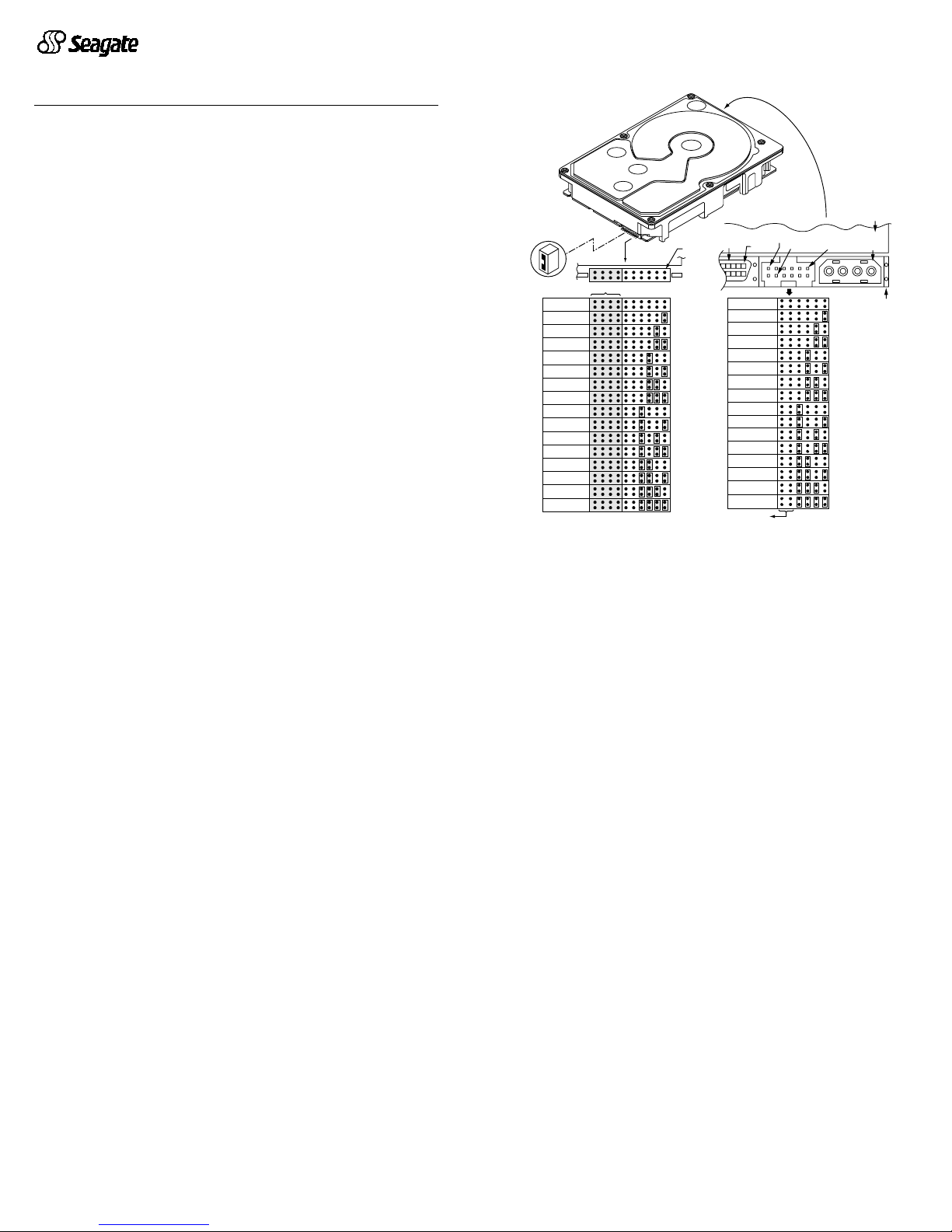
1. Set the SCSI ID
Deter mine which SCSI I Ds ar e alre ady be ing used i n the s ystem and t hen
assig n this di sc drive a SCSI ID that isn’t alr eady being use d. Use the J6
connector located on the front of the drive to set the SCSI ID (see Figure 1).
• Most ST318404 drives are factory set with the SCSI ID set at 0. If this is
the only S CS I drive in your syst em a nd the r e are no ot her SCSI devices on
the daisychain, you can leave this drive’s SCSI ID set to 0 and proceed to
the next step.
• The host system’s SCSI controller usuall y uses SCSI ID 7.
• If you have an S T318404LC model drive, t he host nor mally set s the ID
over the I/O interface, so you don’t need to worry about this step.
• Some systems provide a cable designed to connect to the J5 jumper block
on the drive to remotely set the ID. You can connect this cable to J5 and
use the host-provided remote switch to set the SCSI ID.
Figure 1. Setting the SCSI ID
2. Configure termination
If you are installing the drive in a system that has other SCSI devices
instal led , t e rminate only the end devi ces on the SCSI bus (ca ble ) . This dr i ve
does no t h ave intern al termin at ors or any o th er way of addin g in te rnal te rmination on the dr ive. You must provide exte r nal te r mina tion w hen ter min ation
is requ ired. Thi s is n orm al ly do ne by a ddin g an i nlin e te rm inato r on the e nd
of the ca ble. Se e Fig ure 3 for an ill us tratio n show ing a sys tem confi gu ration
that uses an extern a l ter m in ato r.
• Use active (ANSI SCSI-2 Alternative 2) single-ended terminators when
terminating a bus operating in single-ended mode.
• Use SPI-2 -complia nt active low volta ge different ial termin ators whe n terminating a SCSI Ultra2 bus operating in LVD mode.
• The host adapter is normally on the end of the bus and internally terminated. You can configure your bus with another device on the end if you
remove termination from the ho st adapter.
3. Configure te rminator power
Terminators have to get power from some source. The default configuration
results in the dri ve not supply ing ter mination p ower to the bus. You should
norm ally leave this dr ive se t at thi s defaul t unl ess your host sy stem req uires
the drive to supply term ination pow er to the bus. To configure this d rive to
supply termination power to the bus, place a jumper on J2 pins 1 and 2 as
shown in Figure 2.
• Host systems designed to use LC drives normally provide termination
power from the host adapter or other source. For this reason, LC model
drives cannot be configured to provide termination power to the bus.
SCSI ID = 0 (default)
Jumper Plug
(enlarged to
show detail)
J6
Drive
Front
Pin 1
Reserved
A2A1A0A
L
E
D
R
E
S
3
SCSI ID = 1
SCSI ID = 2
SCSI ID = 3
SCSI ID = 4
SCSI ID = 5
SCSI ID = 6
SCSI ID = 7
SCSI ID = 8
SCSI ID = 9
SCSI ID = 10
SCSI ID = 11
SCSI ID = 12
SCSI ID = 13
SCSI ID = 14
SCSI ID = 15
J1
DC Power
J1
68 Pin
SCSI I/O
Connector
Drive HDA
Rear
SCSI ID = 8
SCSI ID = 9
SCSI ID = 10
SCSI ID = 11
SCSI ID = 12
SCSI ID = 13
SCSI ID = 14
SCSI ID = 15
A
not used
3A2A1
SCSI ID = 0
SCSI ID = 1
SCSI ID = 2
SCSI ID = 3
SCSI ID = 4
SCSI ID = 5
SCSI ID = 6
SCSI ID = 7
A
0
J5
Pin 1
4P 3P 2P 1P
PCBA
Pin 1
+5V
Ground
(default)
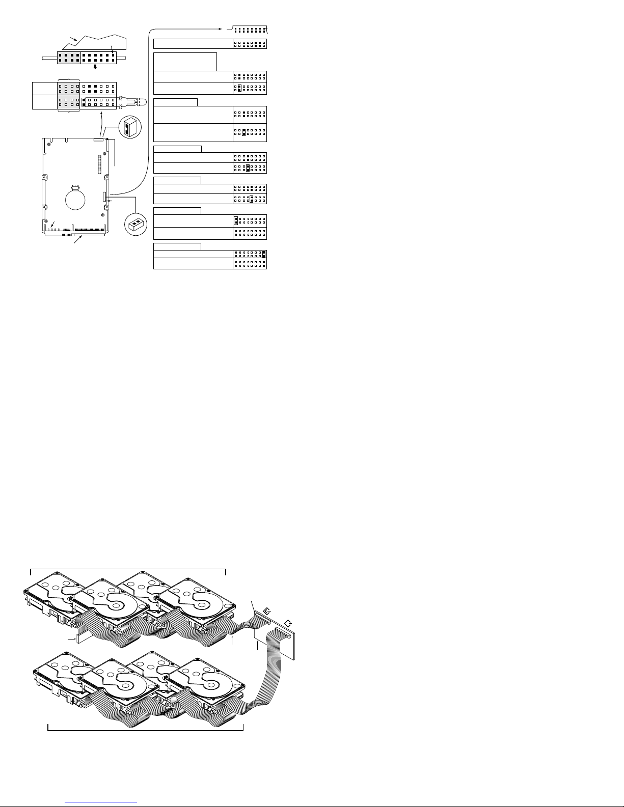
Figure 2. Option select jumpers.
4. Connect the drive activity LED (optional)
Connec t the D ri ve A c tiv it y L E D ca ble to J 6 pins 11 an d 12 (see Fig ur e 2), or
conne ct a drive ID and Dr ive Activity LED cable to J5, depen ding on host
system requirements.
5. Check the other available jumper settings
Select other options on J2 as illustrat ed in Figure 2. Do not change these
unless instructed to do so by the host system documentation.
6. Mount the drive in the host system and connect cables
Note.
LC drives are designed to be attached to a carrier or tray and inserted
into the host system without I/O or power cables.
Caution.
Some mounting kits may contain screws that are too long to be
fully tightened without causing damage to the drive. The maximum
length for screws to exte nd into the dr ive moun ting holes is 0.15
inch (3.82 mm), measured from the outer surface of the drive.
a. Mount LW m odel drives to the host syst em’s chassis using four 6-32
UNC screws. Two mounting holes are in each side of the drive and there
are four mounting holes in the bottom of the drive. Do not over-tighten or
force the screws. You can mount the drive in any orientation.
b. Connec t the SCSI I /O cable in to the dri ve’s SCSI connector. Take care
not to s tre tch o r cr imp this cable, and do no t blo ck th e syste m ’s cooling
air flow with the cable.
Note.
For Ultra2 a nd faster op eration, special twi sted pair LVD cables are
required
.
c. Connect the DC power cable to the drive. See Figure 3.
Figure 3. Cable connections and external termination
7. Format the drive
The drive has been
low le v el
formatted at the factory. You do not need to perform another low level format on this drive unless you decide to perform certain di agno st ics t hro ugh the ho st ada pter. If yo u do de cide to p erfor m a low
level f ormat, do n ot abort the format as this is likely to make the drive inoperable. A low level forma t, with verif y turned o n, will typi cally take u p to one
hour.
Protect against power failure or other power interruptions during the format.
a. Turn on DC power to the h ost system.
b. Boot t he system from a system floppy, CD, or from a previously installed
hard disc drive if there is one.
c. Format the drive.
Caution.
Formatt ing a dr ive erases a ll user d ata. Be s ure that yo u understand th is pri nciple before form attin g any hard di sc dr ive. It is not
necess ary to format a drive that previously has been used to store
data, unless your intention is to erase all user da ta. Seag ate is not
responsible for lost user data.
Cheetah disc drives are designed to operate with a variety of operating systems. Ple as e refe r to yo ur s yst em or S C SI con tro ller ma nual for infor m ation
about formatt ing an d s etting up t h e d r i ve. Som e quick desk top syste m notes
are provided below.
•
Microsoft
TM
.
Set the drive type in CMOS to “
Zero,” “None,”
or “
No hard
drive i nsta lled
.” Use FDISK.EXE an d FORMAT.EXE. Systems using Win -
dows 98 or later can create one single partition (drive letter) on the drive.
•
Macintosh
TM
.
Use a third-party drive utility (most revisions of Apple’s HD
Setup utility only work with drives having special Apple firmware).
Troubleshoot ing
•
Drive does not spin up.
Check cables and all jumper settings. Make sure
cable pin 1 (edge stripe) matches PCB pin 1.
•
Drive spins , but no LED on/off ac tivity.
Check SCSI ID setti ng. Set the
ID so th at ea ch device on the SCSI chai n h as its own un ique ID. See al so
the next item below. Host I/O controller is usually ID 7.
•
Computer does not seem to recognize the drive.
Verify that the drive is
enabled by the SCSI host adapter setup utility.
•
FDISK does not de tect the drive.
Run the FDISK program locat ed on
your Windows startup diskette. Type fdisk/status to verify that your hard
driv e is present.
Seagate support services
For online information about Seagate products, visit www.seagate.com or email your disc questions to DiscSupport@Seagate.com.
If you need help installing your drive, consult your dealer first. If you need
additio nal help, call a Seagate technical suppor t specialist . Before cal ling,
note your system configuration and drive model number (
ST318404LW,
ST318404LC, ST39204LW, or ST39204LC).
Africa +31-20-316-7222 Poland 00 800-311 12 38
Aus tralia +61-2-9725-3366 Spain 900-98 31 24
Austria 0 800-20 12 90 Sweden 0 207 90 073
Belgium 0 800-74 876 Switzerland 0 800-83 84 11
Denmark 80 88 12 66 Singapore +65-488-75 84
France 0 800-90 90 52 Taiwan +886-2-2514-2237
Germany 0 800-182 6831 T urkey 00 800-31 92 91 40
Hong Kong 800-90-0474 United Kingdom 0 800-783 5177
Ireland 1 800-55 21 22 USA/Canada/ 1-800 SEAGATE or
Italy 800-790695 Latin America +1-405-936-1234
Middl e East +31-20-316-7222 Othe r European
Nether lands 0 800-732-4 283 count ries +31-20-316-7222
Norway 800-113 91
Warranty.
Contact your place of purchase or our web site (above).
Return Merchandise Authorization (RMA).
Before returning the drive, verify that it is
defective. Seagate Worldwide customer service centers are the only facilities authorized
to service Seagate drives. Contact nearest center for return procedures and trade regulations.
Shipping the drive
Caution.
Back up the data before ship ping. Seagate assumes no responsibil ity for
data lost during shipping or service. Shipping drive in an unapproved container voids the
warranty. Pack the drive with original box and packing materials. Use no other materials.
This prevents electrical and physical damage in transit.
© 1999, 2000 Seagate Technology, LLC All rights reserved
Publication number: 75789507, Rev. B, August 2000, Printed in U.S.A.
Seagate, Seagate Technology, the Seagate logo, and Cheet ah are either regist ered
trademarks or tr ademarks of Seagate Technol ogy, L LC. All other trademarks are the
property of their respective owners.
Enable parity check of SCSI bus.
Disable parity check.
J2
Pin 1
Reserved Positions
Parity Check option
Single-ended I/O
Terminator Power
Write protect = Off (enables writing).
Write protect = On (disables writing).
Write Protect option
Disable the Delay Motor Start option.
Motor start delay equal to the
SCSI ID multiplied by 12 seconds.
Delay Motor Start option (valid
only if the Enable Motor Start
jumper is not connected)
Enable motor start. The drive waits for
the Start Unit command from the host
before starting the spindle motor.
Disable motor start (default). The
drive starts according to the Delay
Motor Start option.
Motor Start option
Pin 1
End
SCSI I/O
Connector
Drive with
HDA up, PCB
down, viewed
from front
Pin 1
DC Power
Connector
J2
Drive Front
J6
Pin 1
HDA
J6
A2A3A1A
0
Reserved
Remote
LED
L
E
D
R
E
S
Reserved
Shipped with cover installed.
Do not remove.
Do not install jumpers
on these four positions.
J6 Jumper
CATH
11
12
J2 Jumper
(default)
(default)
(default)
(default)
A jumper here forces single-ended
I/O operation.
No jumper allows host to select either
single-ended or LVD operation.
Host adapter or other device provides
term. power to external terminator.
Term. Power to SCSI Bus
(default)
(default)
Pin 1
(check your
adapter for
Pin 1 location)
Host
Adapter
PCB
Twisted Pair
LVD Cable
Ultra160 or Ultra2 LVD bus segment
SPI-2 compliant
active LVD
external terminator
on the end of
the cable
SCSI LVD/SE
SCSI SE
Ultra SCSI SE bus segment
 Loading...