


. . . . . . . . . . . . . . . . . . . . . . . . . . . . . . . . . . . . . . . . . . . . . . . . .
Cheetah 18LP FC Disc Drive
. . . . . . . . . . . . . . . . . . . . . . . . . . . . . . . . . . . . . . . . . . . . . . . . .
ST318203FC
. . . . . . . . . . . . . . . . . . . . . . . . . . . . . . . . . . . . . . . . . . . . . . . . .
ST39103FC
. . . . . . . . . . . . . . . . . . . . . . . . . . . . . . . . . . . . . . . . . . . . . . . . .
. . . . . . . . . . . . . . . . . . . . . . . . . . . . . . . . . . . . . . . . . . . . . . . . .
Product Manual, Volume 1
. . . . . . . . . . . . . . . . . . . . . . . . . . . . . . . . . . . . . . . . . . . . . . . . .


. . . . . . . . . . . . . . . . . . . . . . . . . . . . . . . . . . . . . . . . . . . . . . . . .
Cheetah 18LP FC Disc Drive
. . . . . . . . . . . . . . . . . . . . . . . . . . . . . . . . . . . . . . . . . . . . . . . . .
ST318203FC
. . . . . . . . . . . . . . . . . . . . . . . . . . . . . . . . . . . . . . . . . . . . . . . . .
ST39103FC
. . . . . . . . . . . . . . . . . . . . . . . . . . . . . . . . . . . . . . . . . . . . . . . . .
. . . . . . . . . . . . . . . . . . . . . . . . . . . . . . . . . . . . . . . . . . . . . . . . .
Product Manual, Volume 1
. . . . . . . . . . . . . . . . . . . . . . . . . . . . . . . . . . . . . . . . . . . . . . . . .

© 1998, 1999 Seagate Technology, Inc. All rights reserved
August 1999
Publication number: 83329420, Rev. D
Seagate, Seagate Technology, and the Seagate logo are registered trademarks of Seagate Technology, Inc. Cheetah, SeaFAX, SeaFONE, SeaBOARD, and SeaTDD are either trademarks or
registered trademarks of Seagate Technology, Inc. or one of its subsidiaries. All other trademarks
or registered trademarks are the property of their respective owners.
No part of this publication may be reproduced in any form without written permission from
Seagate Technology, Inc.
Printed in the United States of America

Revision status summary sheet
Revision Date Writer/Engineer Sheets Affected
A 03/29/99 L. Newman/P. Kassel Class A Release
B 05/20/99 L. Newman/D. Rusch ECR: DJD51090.
C 06/16/99 L. Newman/D. Rusch ECR: DJD51095.
D 07/30/99 L. Newman/D. Rusch ECR: DJD51099.


Cheetah 1 8LP FC P r od uc t Manual, Rev. D v
Contents
1.0 Scope . . . . . . . . . . . . . . . . . . . . . . . . . . . . . . . . . . . . . . . . . . . . . . . . . . . . . . . . . . . . . . . . . . . . . . . . . . 1
2.0 Applicable standards and reference documentation. . . . . . . . . . . . . . . . . . . . . . . . . . . . . . . . . . . . 3
2.1 Standards. . . . . . . . . . . . . . . . . . . . . . . . . . . . . . . . . . . . . . . . . . . . . . . . . . . . . . . . . . . . . . . . . 3
2.1.1 Electromagnetic compatibility . . . . . . . . . . . . . . . . . . . . . . . . . . . . . . . . . . . . . . . . . . 3
2.1.2 Electromagnetic compliance . . . . . . . . . . . . . . . . . . . . . . . . . . . . . . . . . . . . . . . . . . . 3
2.2 Reference documents . . . . . . . . . . . . . . . . . . . . . . . . . . . . . . . . . . . . . . . . . . . . . . . . . . . . . . . 4
3.0 General descr iption. . . . . . . . . . . . . . . . . . . . . . . . . . . . . . . . . . . . . . . . . . . . . . . . . . . . . . . . . . . . . . . 5
3.1 Standard features. . . . . . . . . . . . . . . . . . . . . . . . . . . . . . . . . . . . . . . . . . . . . . . . . . . . . . . . . . . 6
3.2 Media description. . . . . . . . . . . . . . . . . . . . . . . . . . . . . . . . . . . . . . . . . . . . . . . . . . . . . . . . . . . 6
3.3 Performance. . . . . . . . . . . . . . . . . . . . . . . . . . . . . . . . . . . . . . . . . . . . . . . . . . . . . . . . . . . . . . . 6
3.4 Reliability . . . . . . . . . . . . . . . . . . . . . . . . . . . . . . . . . . . . . . . . . . . . . . . . . . . . . . . . . . . . . . . . . 6
3.5 Unformatted and formatted capacities . . . . . . . . . . . . . . . . . . . . . . . . . . . . . . . . . . . . . . . . . . . 7
3.6 Programmable drive capacity. . . . . . . . . . . . . . . . . . . . . . . . . . . . . . . . . . . . . . . . . . . . . . . . . . 7
3.7 Factory-installed accessories. . . . . . . . . . . . . . . . . . . . . . . . . . . . . . . . . . . . . . . . . . . . . . . . . . 7
3.8 Factory-installed options . . . . . . . . . . . . . . . . . . . . . . . . . . . . . . . . . . . . . . . . . . . . . . . . . . . . . 7
3.9 User-installed accessories. . . . . . . . . . . . . . . . . . . . . . . . . . . . . . . . . . . . . . . . . . . . . . . . . . . . 7
4.0 Performance characteristics . . . . . . . . . . . . . . . . . . . . . . . . . . . . . . . . . . . . . . . . . . . . . . . . . . . . . . . 9
4.1 Internal drive characteristics. . . . . . . . . . . . . . . . . . . . . . . . . . . . . . . . . . . . . . . . . . . . . . . . . . . 9
4.2 Seek performance characteristics . . . . . . . . . . . . . . . . . . . . . . . . . . . . . . . . . . . . . . . . . . . . . . 9
4.2.1 Access time . . . . . . . . . . . . . . . . . . . . . . . . . . . . . . . . . . . . . . . . . . . . . . . . . . . . . . . 9
4.2.2 Format command execution time for ≥ 512-byte sectors . . . . . . . . . . . . . . . . . . . . . 9
4.2.3 General performance characteristics . . . . . . . . . . . . . . . . . . . . . . . . . . . . . . . . . . . 10
4.3 Start/stop time . . . . . . . . . . . . . . . . . . . . . . . . . . . . . . . . . . . . . . . . . . . . . . . . . . . . . . . . . . . . 10
4.4 Prefetch/multi-segmented cache control . . . . . . . . . . . . . . . . . . . . . . . . . . . . . . . . . . . . . . . . 10
4.5 Cache operation. . . . . . . . . . . . . . . . . . . . . . . . . . . . . . . . . . . . . . . . . . . . . . . . . . . . . . . . . . . 1 1
4.5.1 Caching write data . . . . . . . . . . . . . . . . . . . . . . . . . . . . . . . . . . . . . . . . . . . . . . . . . 11
4.5.2 Prefetch operation . . . . . . . . . . . . . . . . . . . . . . . . . . . . . . . . . . . . . . . . . . . . . . . . . 12
5.0 Reliability specifications . . . . . . . . . . . . . . . . . . . . . . . . . . . . . . . . . . . . . . . . . . . . . . . . . . . . . . . . . 13
5.1 Error rates . . . . . . . . . . . . . . . . . . . . . . . . . . . . . . . . . . . . . . . . . . . . . . . . . . . . . . . . . . . . . . . 13
5.1.1 Environmental interference. . . . . . . . . . . . . . . . . . . . . . . . . . . . . . . . . . . . . . . . . . . 13
5.1.2 Write errors. . . . . . . . . . . . . . . . . . . . . . . . . . . . . . . . . . . . . . . . . . . . . . . . . . . . . . . 13
5.1.3 Seek errors. . . . . . . . . . . . . . . . . . . . . . . . . . . . . . . . . . . . . . . . . . . . . . . . . . . . . . . 13
5.2 Reliability and service . . . . . . . . . . . . . . . . . . . . . . . . . . . . . . . . . . . . . . . . . . . . . . . . . . . . . . . 1 4
5.2.1 Mean time between failure (MTB F) . . . . . . . . . . . . . . . . . . . . . . . . . . . . . . . . . . . . 14
5.2.2 Field failure rate vs time . . . . . . . . . . . . . . . . . . . . . . . . . . . . . . . . . . . . . . . . . . . . . 14
5.2.3 Preve ntive maintenan ce . . . . . . . . . . . . . . . . . . . . . . . . . . . . . . . . . . . . . . . . . . . . . 15
5.2.4 Service life . . . . . . . . . . . . . . . . . . . . . . . . . . . . . . . . . . . . . . . . . . . . . . . . . . . . . . . 15
5.2.5 Service philosophy . . . . . . . . . . . . . . . . . . . . . . . . . . . . . . . . . . . . . . . . . . . . . . . . . 15
5.2.6 Service tools. . . . . . . . . . . . . . . . . . . . . . . . . . . . . . . . . . . . . . . . . . . . . . . . . . . . . . 15
5.2.7 Hot plugging the drive. . . . . . . . . . . . . . . . . . . . . . . . . . . . . . . . . . . . . . . . . . . . . . . 15
5.2.8 S.M.A.R.T. . . . . . . . . . . . . . . . . . . . . . . . . . . . . . . . . . . . . . . . . . . . . . . . . . . . . . . . 16
5.2.9 Product warranty. . . . . . . . . . . . . . . . . . . . . . . . . . . . . . . . . . . . . . . . . . . . . . . . . . . 17
6.0 Physical/electrical specifications . . . . . . . . . . . . . . . . . . . . . . . . . . . . . . . . . . . . . . . . . . . . . . . . . . 19
6.1 AC power requirements . . . . . . . . . . . . . . . . . . . . . . . . . . . . . . . . . . . . . . . . . . . . . . . . . . . . . 19
6.2 DC power requirements. . . . . . . . . . . . . . . . . . . . . . . . . . . . . . . . . . . . . . . . . . . . . . . . . . . . . 19
6.2.1 Conduct ed noise immu nity . . . . . . . . . . . . . . . . . . . . . . . . . . . . . . . . . . . . . . . . . . . 20
6.2.2 Power sequenc ing . . . . . . . . . . . . . . . . . . . . . . . . . . . . . . . . . . . . . . . . . . . . . . . . . 20
6.2.3 Current profiles. . . . . . . . . . . . . . . . . . . . . . . . . . . . . . . . . . . . . . . . . . . . . . . . . . . . 20
6.3 Power dissipation. . . . . . . . . . . . . . . . . . . . . . . . . . . . . . . . . . . . . . . . . . . . . . . . . . . . . . . . . . 23
6.4 Environmental limits. . . . . . . . . . . . . . . . . . . . . . . . . . . . . . . . . . . . . . . . . . . . . . . . . . . . . . . . 2 4
6.4.1 Temperature. . . . . . . . . . . . . . . . . . . . . . . . . . . . . . . . . . . . . . . . . . . . . . . . . . . . . . 24
6.4.2 Relative humidity . . . . . . . . . . . . . . . . . . . . . . . . . . . . . . . . . . . . . . . . . . . . . . . . . . 25

vi Cheetah 18LP FC Product Manual, Rev. D
6.4.3 Effective altitude (sea level). . . . . . . . . . . . . . . . . . . . . . . . . . . . . . . . . . . . . . . . . . .25
6.4.4 Shock and vibration. . . . . . . . . . . . . . . . . . . . . . . . . . . . . . . . . . . . . . . . . . . . . . . . .26
6.4.5 Air cleanliness . . . . . . . . . . . . . . . . . . . . . . . . . . . . . . . . . . . . . . . . . . . . . . . . . . . . .28
6.4.6 Acoustics . . . . . . . . . . . . . . . . . . . . . . . . . . . . . . . . . . . . . . . . . . . . . . . . . . . . . . . . .28
6.4.7 Electromagnetic susceptibility . . . . . . . . . . . . . . . . . . . . . . . . . . . . . . . . . . . . . . . . .28
6.5 Mechanical specifications . . . . . . . . . . . . . . . . . . . . . . . . . . . . . . . . . . . . . . . . . . . . . . . . . . . .29
7.0 Defect and error management . . . . . . . . . . . . . . . . . . . . . . . . . . . . . . . . . . . . . . . . . . . . . . . . . . . . .31
7.1 Drive internal defects/errors . . . . . . . . . . . . . . . . . . . . . . . . . . . . . . . . . . . . . . . . . . . . . . . . . .31
7.2 Drive error recovery procedures . . . . . . . . . . . . . . . . . . . . . . . . . . . . . . . . . . . . . . . . . . . . . . .31
7.3 FC-AL system errors. . . . . . . . . . . . . . . . . . . . . . . . . . . . . . . . . . . . . . . . . . . . . . . . . . . . . . . .32
8.0 Installation . . . . . . . . . . . . . . . . . . . . . . . . . . . . . . . . . . . . . . . . . . . . . . . . . . . . . . . . . . . . . . . . . . . . .33
8.1 Drive ID/option selection . . . . . . . . . . . . . . . . . . . . . . . . . . . . . . . . . . . . . . . . . . . . . . . . . . . . .33
8.2 LED connections. . . . . . . . . . . . . . . . . . . . . . . . . . . . . . . . . . . . . . . . . . . . . . . . . . . . . . . . . . .33
8.2.1 J6 connector requirements . . . . . . . . . . . . . . . . . . . . . . . . . . . . . . . . . . . . . . . . . . .34
8.3 Drive orientation . . . . . . . . . . . . . . . . . . . . . . . . . . . . . . . . . . . . . . . . . . . . . . . . . . . . . . . . . . .34
8.4 Cooling . . . . . . . . . . . . . . . . . . . . . . . . . . . . . . . . . . . . . . . . . . . . . . . . . . . . . . . . . . . . . . . . . .34
8.4.1 Air flow. . . . . . . . . . . . . . . . . . . . . . . . . . . . . . . . . . . . . . . . . . . . . . . . . . . . . . . . . . .35
8.5 Drive mounting . . . . . . . . . . . . . . . . . . . . . . . . . . . . . . . . . . . . . . . . . . . . . . . . . . . . . . . . . . . .35
8.6 Grounding . . . . . . . . . . . . . . . . . . . . . . . . . . . . . . . . . . . . . . . . . . . . . . . . . . . . . . . . . . . . . . . .36
9.0 Interface requiremen ts. . . . . . . . . . . . . . . . . . . . . . . . . . . . . . . . . . . . . . . . . . . . . . . . . . . . . . . . . . . .37
9.1 FC-AL features . . . . . . . . . . . . . . . . . . . . . . . . . . . . . . . . . . . . . . . . . . . . . . . . . . . . . . . . . . . .37
9.1.1 Fibre Channel link service frames . . . . . . . . . . . . . . . . . . . . . . . . . . . . . . . . . . . . . .37
9.1.2 Fibre Channel task managem ent functions . . . . . . . . . . . . . . . . . . . . . . . . . . . . . . .37
9.1.3 Fibre Channel task managem ent respons es . . . . . . . . . . . . . . . . . . . . . . . . . . . . . .37
9.1.4 Fibre Channel port login. . . . . . . . . . . . . . . . . . . . . . . . . . . . . . . . . . . . . . . . . . . . . .38
9.1.5 Fibre Channel port login accept. . . . . . . . . . . . . . . . . . . . . . . . . . . . . . . . . . . . . . . .39
9.1.6 Fibre Channel Proc ess Login. . . . . . . . . . . . . . . . . . . . . . . . . . . . . . . . . . . . . . . . . .39
9.1.7 Fibre Channel Proc ess Login Accept . . . . . . . . . . . . . . . . . . . . . . . . . . . . . . . . . . . .39
9.1.8 Fibre Channel fabric login . . . . . . . . . . . . . . . . . . . . . . . . . . . . . . . . . . . . . . . . . . . .40
9.1.9 Fibre Channel fabric accept login . . . . . . . . . . . . . . . . . . . . . . . . . . . . . . . . . . . . . .41
9.1.10 Fibre Channel Arbitrated Loop options . . . . . . . . . . . . . . . . . . . . . . . . . . . . . . . . . .42
9.2 Dual port support. . . . . . . . . . . . . . . . . . . . . . . . . . . . . . . . . . . . . . . . . . . . . . . . . . . . . . . . . . .42
9.3 SCSI commands supported . . . . . . . . . . . . . . . . . . . . . . . . . . . . . . . . . . . . . . . . . . . . . . . . . .43
9.3.1 Inquiry data . . . . . . . . . . . . . . . . . . . . . . . . . . . . . . . . . . . . . . . . . . . . . . . . . . . . . . .46
9.3.2 Mode Sense data. . . . . . . . . . . . . . . . . . . . . . . . . . . . . . . . . . . . . . . . . . . . . . . . . . .46
9.4 Miscellaneous operating features and con ditions . . . . . . . . . . . . . . . . . . . . . . . . . . . . . . . . . .50
9.5 FC-AL physical interface. . . . . . . . . . . . . . . . . . . . . . . . . . . . . . . . . . . . . . . . . . . . . . . . . . . . .51
9.5.1 Physical characteristics . . . . . . . . . . . . . . . . . . . . . . . . . . . . . . . . . . . . . . . . . . . . . .51
9.5.2 Connector requirem ent s . . . . . . . . . . . . . . . . . . . . . . . . . . . . . . . . . . . . . . . . . . . . .52
9.5.3 Electrical description . . . . . . . . . . . . . . . . . . . . . . . . . . . . . . . . . . . . . . . . . . . . . . . .53
9.5.4 Pin descriptions . . . . . . . . . . . . . . . . . . . . . . . . . . . . . . . . . . . . . . . . . . . . . . . . . . . .53
9.5.5 FC-AL transmitters and receivers . . . . . . . . . . . . . . . . . . . . . . . . . . . . . . . . . . . . . .54
9.5.6 Power. . . . . . . . . . . . . . . . . . . . . . . . . . . . . . . . . . . . . . . . . . . . . . . . . . . . . . . . . . . .54
9.5.7 Fault LED Out . . . . . . . . . . . . . . . . . . . . . . . . . . . . . . . . . . . . . . . . . . . . . . . . . . . . .54
9.5.8 Active LED Out . . . . . . . . . . . . . . . . . . . . . . . . . . . . . . . . . . . . . . . . . . . . . . . . . . . .54
9.5.9 Enable port bypass signal s . . . . . . . . . . . . . . . . . . . . . . . . . . . . . . . . . . . . . . . . . . .55
9.5.10 Motor start controls . . . . . . . . . . . . . . . . . . . . . . . . . . . . . . . . . . . . . . . . . . . . . . . . .55
9.5.11 SEL_6 through SEL_0 ID lines . . . . . . . . . . . . . . . . . . . . . . . . . . . . . . . . . . . . . . . .55
9.6 Signal characteristics . . . . . . . . . . . . . . . . . . . . . . . . . . . . . . . . . . . . . . . . . . . . . . . . . . . . . . .58
9.6.1 TTL input characteristics . . . . . . . . . . . . . . . . . . . . . . . . . . . . . . . . . . . . . . . . . . . . .58
9.6.2 LED driver signals . . . . . . . . . . . . . . . . . . . . . . . . . . . . . . . . . . . . . . . . . . . . . . . . . .58
9.6.3 Differential PECL output . . . . . . . . . . . . . . . . . . . . . . . . . . . . . . . . . . . . . . . . . . . . .58
9.6.4 Differential PECL input. . . . . . . . . . . . . . . . . . . . . . . . . . . . . . . . . . . . . . . . . . . . . . .59
10.0 Seagate Technology support services. . . . . . . . . . . . . . . . . . . . . . . . . . . . . . . . . . . . . . . . . . . . . . .61

Cheetah 1 8LP FC P r od uc t Manual, Rev. D vii
List of Figures
Figure 1. Cheetah 18LP FC family disc drive . . . . . . . . . . . . . . . . . . . . . . . . . . . . . . . . . . . . . . . . . . . . . 1
Figure 2. Cheetah 18LP FC disc drive . . . . . . . . . . . . . . . . . . . . . . . . . . . . . . . . . . . . . . . . . . . . . . . . . . 5
Figure 3. Typical ST318203FC drive +12V current profile . . . . . . . . . . . . . . . . . . . . . . . . . . . . . . . . . . 20
Figure 4. Typical ST39103FC drive +12V current profile . . . . . . . . . . . . . . . . . . . . . . . . . . . . . . . . . . . 21
Figure 5. Typical ST318203FC drive +5V current profile . . . . . . . . . . . . . . . . . . . . . . . . . . . . . . . . . . . 22
Figure 6. Typical ST39103FC drive +5V current profile . . . . . . . . . . . . . . . . . . . . . . . . . . . . . . . . . . . . 22
Figure 7. DC current and power vs. input/output operations per second . . . . . . . . . . . . . . . . . . . . . . . 23
Figure 8. DC current and power vs. input/output operations per second . . . . . . . . . . . . . . . . . . . . . . . 23
Figure 9. Locations of PCBA components listed in Table 2 . . . . . . . . . . . . . . . . . . . . . . . . . . . . . . . . . 25
Figure 10. Recommended mounting . . . . . . . . . . . . . . . . . . . . . . . . . . . . . . . . . . . . . . . . . . . . . . . . . . . 2 7
Figure 11. Mounting configuration dimensions . . . . . . . . . . . . . . . . . . . . . . . . . . . . . . . . . . . . . . . . . . . . 29
Figure 12. Physical interface . . . . . . . . . . . . . . . . . . . . . . . . . . . . . . . . . . . . . . . . . . . . . . . . . . . . . . . . . 33
Figure 13. LED indicator connector . . . . . . . . . . . . . . . . . . . . . . . . . . . . . . . . . . . . . . . . . . . . . . . . . . . . 34
Figure 14. Air flow . . . . . . . . . . . . . . . . . . . . . . . . . . . . . . . . . . . . . . . . . . . . . . . . . . . . . . . . . . . . . . . . . . 35
Figure 15. Physical interface . . . . . . . . . . . . . . . . . . . . . . . . . . . . . . . . . . . . . . . . . . . . . . . . . . . . . . . . . 51
Figure 16. Port bypass circuit physical interconnect . . . . . . . . . . . . . . . . . . . . . . . . . . . . . . . . . . . . . . . 51
Figure 17. FC-AL SCA device connector dimensions . . . . . . . . . . . . . . . . . . . . . . . . . . . . . . . . . . . . . . 52
Figure 18. J6 connector dimensions . . . . . . . . . . . . . . . . . . . . . . . . . . . . . . . . . . . . . . . . . . . . . . . . . . . . 52
Figure 19. FC-AL transmitters and receivers . . . . . . . . . . . . . . . . . . . . . . . . . . . . . . . . . . . . . . . . . . . . . 5 4
Figure 20. Transmit eye diagram . . . . . . . . . . . . . . . . . . . . . . . . . . . . . . . . . . . . . . . . . . . . . . . . . . . . . . 59
Figure 21. Receive eye diagram . . . . . . . . . . . . . . . . . . . . . . . . . . . . . . . . . . . . . . . . . . . . . . . . . . . . . . . 59

Cheetah 1 8LP FC P r od uc t Manual, Rev. D 1
1.0 Scope
This manual describes Seagate Technology®, Inc. Cheetah 18LP FC (Fibre Channel) disc drives.
Cheetah 18LP FC dr ives support the Fibre Chann el Ar bitrated Lo op and SCSI Fi bre Chann el Pr otoco l specifi-
cations to the extent described in this manual. The Fibre Channel Interface Manual (part number 77767496)
describes the general Fibre Channel Arbitrated Loop characteristics of this and other Seag ate Fibre Channel
drive s.
Figure 1.
Cheetah 18LP FC
family disc drive


Cheetah 1 8LP FC P r od uc t Manual, Rev. D 3
2.0 Applicable standards and reference documentation
The drive has been developed as a system peripheral to the highest standards of design and construction. The
drive depends upon its hos t equipment to provide adequat e power and environment in order to ac hieve optimum performance and c ompliance with applicable industry and g overnmental regu lations. Special attention
must be given in the areas of safety, power distribution, shielding, audible noise control, and temperature regulation. In part icular, the drive must be securely mounted in order to guarantee the specified pe rformance c haracteristics. Mounting by bottom holes must meet the requirements of Section 8.5.
2.1 Standards
The Cheetah 18LP FC family complies with S eagate standards as noted in the appropria te sections of this
manual and the Seagate Fibre Channel Interface Manual, part number 77767496.
The Cheetah 18LP FC disc drive is a UL recognized component per UL1950, CSA certified to CAN/CSA C22.2
No. 950-95, and VDE certified to VDE 0805 and EN60950.
2.1.1 Electromagnetic compatibility
The drive, as deliv e re d , is designed for system integra ti o n a n d installation in to a suitab le e nclosure prior to u se.
As such the drive is supplied as a subassembly and is not subject to Subp art B of Part 15 of the FCC Rules
and Regulations nor the Radio Interference Regulations of the Canadian Department of Communications.
The design characteristics of the drive serve to minimize radiation when installed in an enclosure that provides
reasonable shielding. As such, the drive is capable of meeting the Class B limits of the FCC Rules and Regulations of the Canadian Department of Communications when properly packaged. However, it is the user’s
responsibility to assure that the drive meets the appropriate EMI requirements in their system. Shielded I/O
cables may be required if the enclosure does not provide adequate shielding. If the I/O cables are external to
the enclosure, shielded cables should be used, with the shields grounded to the enclosure and to the host controller.
2.1.1.1 Electromagnetic susceptibility
As a component assembly, the drive is not required to meet any susceptibility performance requirements. It is
the responsibility of those integrating the dri ve within their s ystems to perform thos e tes ts req uired a nd des i gn
their system to ensure that equipment operating in the same system as the drive or external to the system
does not adversely affect the performance of the drive. See Section 5.1.1 and Table 1, DC power requirements.
2.1.2 Electromagnetic compliance
Seagate uses an independ ent laboratory to confir m compliance with the direct ives/standards for CE Marking
and C-Tick Marking. The drive was tested in a representative system for typical applications. The selected system represents the most popular characteristics for test platforms. The system configurations include:
• 486, Pentium, and PowerPC microproces sors
• 3.5-inch floppy disc drive
• Keyboard
• Monitor/display
• Printer
• External modem
• Mouse
Although the test system with this Seagate model complies with the directives/standards, we cannot guarantee
that all systems will comply. The computer manufacturer or system integrator shall confirm EMC compliance
and provide the appropriate marking for their product.
Electromagnetic compliance for the European Union
If this model has the CE Marking it complies with the European Union requirements of the Electromagnetic
Compatibility Directive 89/336/EEC of 03 May 1989 as amended by Directive 92/31/EEC of 28 April 1992 and
Directive 93/68/EEC of 22 July 1993.

4 Cheetah 18LP FC Product Manual, Rev . D
Australian C-Tick
If this model has the C-Tick Marking it complies with the Australia/New Zealand Standard AS/NZS3548 1995
and meets the Electromagnetic Compatibility (EMC) Framework requirements of Australia’s Spectrum Man-
agement Agency (SMA).
2.2 Reference documents
Cheetah 18LP FC Installation Guide
Seagate par t number: 83329430
Fibre Channel Interface Manual
Seagate par t number: 77767496
ANSI Fibre Channel Documents
X3.230-1994 FC Physical and Signaling Interface (FC-PH)
X3.297.1997 FC-PH-2 Fibre Channel Physical and Signaling Interface-2
X3.303.1998 FC-PH-3 Fibre Channel Physical and Signaling Interface-3
X3.272-1996 FC Arbitrated Loop (FC-AL)
X3.269-1996 Fibre Channel Protocol for SCSI (FCP)
NCITS TR-19 Private Loop SCSI Direct Attach (PLDA)
NCITS TR-20 Fabric Loop Attachment (FC-FLA)
SFF-8045 Specification for 40-pin SCA-2 Connector with Parallel Selection.
SFF-8067 Specification for 40-pin SCA-2 Connector with Bidirectional Enclosure Services
Interface.
ANSI Small Computer System Interface (SCSI) Documents
X3.131-1994 (SCSI-2)
X3.270-1996 (SCSI-3) Architecture Model
NCITS 305-199X (SCSI-3) Enclosure Services
30553-001 Specification for Acoustic Test Requirement and Procedures
In case of conflict between this document and any referenced document, this document takes precedence.

Cheetah 1 8LP FC P r od uc t Manual, Rev. D 5
3.0 General description
CheetahTM 18LP FC drives combine dual stripe m agneto re sistive (DSMR) heads, partial respons e/maximum
likelihood (PRML) read channel electronics, embedded servo technology, and a Fibre Channel interface to provide high performance, high capacity da ta storage for a variety of system s includin g engi neering workstations,
network servers, mainframes, and supercomputers.
Cheetah 18LP FC drives are random access storage devices designed to support the Fibre Channel Arbitrated
Loop (FC-AL) and SCSI Fi bre Channel Protocol as de scribed in the ANS I specifications, this document , and
the Fibre Channel Interface Manual (part number 77767496) which describes the general interface characteristics of this dri ve. Cheetah 18 LP FC drives are class ified as intelligent peripherals and pr ovide level 2 conformance (highest level) with the ANSI SCSI-1 standard.
The head and disc assem bly (HDA) is sealed at the factory. Air recircul ates within the HDA through a nonreplaceable filter to maintain a contamination-free HDA environment.
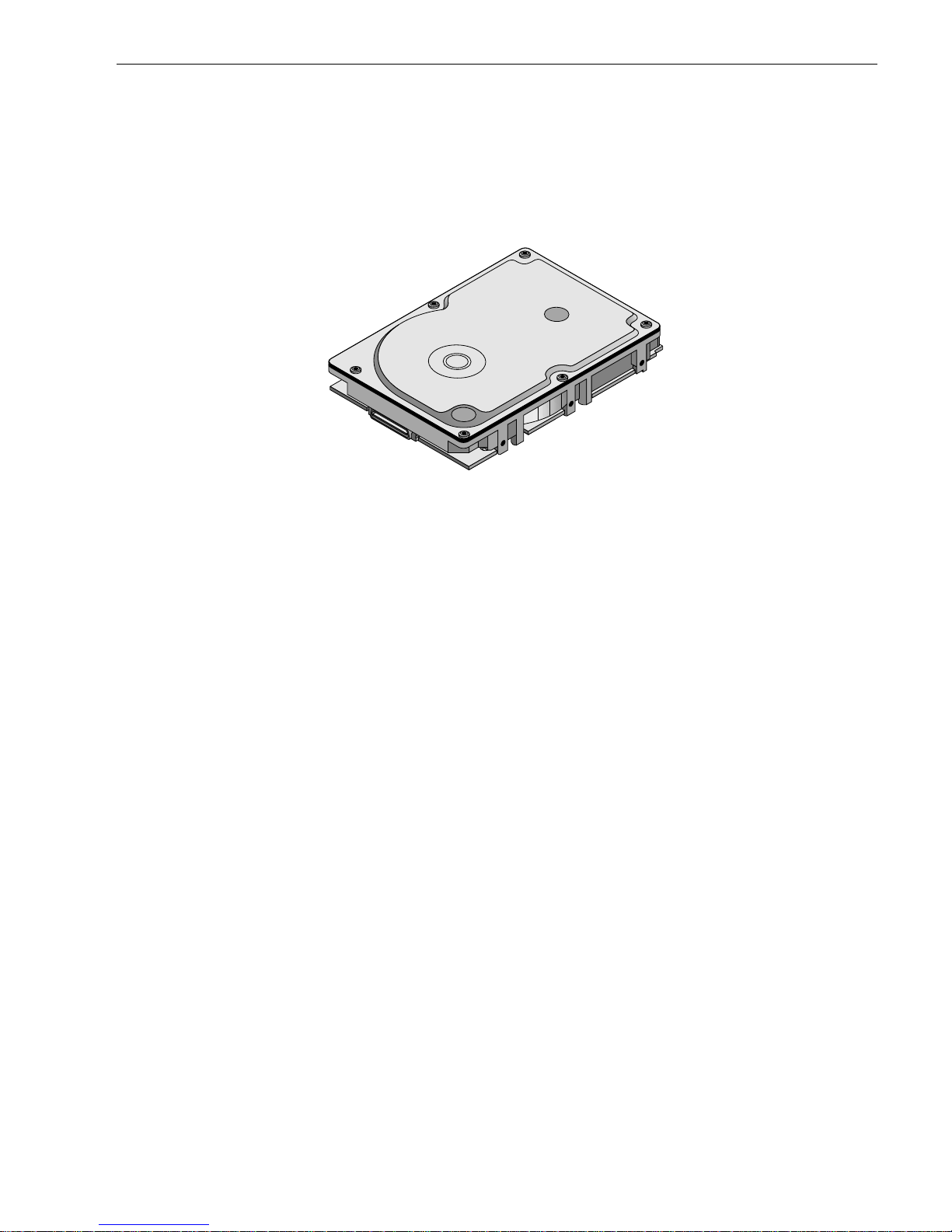
See Figure 2 for an exploded view of the drive. Never disassemble the HDA. This exploded view is for information only. Do not attempt to service items in the sealed enclosure (heads, media, actuator, etc.) as this requires
special facilities. The drive contains no parts replaceable by the user and opening the HDA for any reason
voids your warranty.
Figure 2. Cheetah 18LP FC disc drive
Cheetah 18LP FC dr ives use a dedicated landing zone at the innermos t radius of the media to el iminate the
possibility of destroying or degrading data by landing in the data zone. The heads automatically go to the landing zone when power is removed from the drive.
An automatic shipping lock prevents potential damage to the heads and discs that results from movement during shipping and handling. The shipping lock disengages and t he head load process begins when power is
applied to the drive.
Cheetah 18LP FC drives decode track 0 location data from the servo data embedded on each surface to eliminate mechanical transducer adjustments and related reliability concerns.
The drives also use a high-performance actuator assembly with a low-inertia, balanced, patented, straight arm
design that provides excellent performance with minimal power dissipation.

6 Cheetah 18LP FC Product Manual, Rev . D
3.1 S tandard fe atures
Cheetah 18LP FC drives have the following standard features:
• Integrated dual port FC-AL controller
• Concurrent dual port transfers
• Support for FC arbitrated loop, private and public attachment
• Differential copper FC drivers and receivers
• Downloadable firmware using the FC-AL interface
• Support s SCSI enclosure services via interface connector
• 128-deep task set (queue)
• Support s up to 32 initiators
• Drive selection ID and configuration options are set on the FC-AL backpanel or through interface com-
mands. Jumpers are not used on the drive.
• Supports SCSI Enclosure Services through the interface connector
• Fibre Channel worldwide name uniquely identifies the drive and each por t
• User-selectable logical block size (512 to 4,096 bytes per logical block)
• Selectable frame sizes from 128 to 2,112 bytes
• Industry standard 3.5-inch low profile form factor dimensions
• Programmable logical block reallocation scheme
• Flawed logical block reallocation at format time
• Programmable auto write and read reallocation
• Reed-Solomon error correction code
• Sealed head and disc assembly (HDA)
• No preventive maintenance or adjustments required
• Dedicated head landing zone
• Automatic ship ping lock
• Embedded Grey Code track address to eliminate seek errors
• Self-diagnostics performed at power on
• 1:1 interleave
• Zone bit recording (ZBR)
• Vertical, horizontal, or top down mounting
• Dynamic spindle brake
• 1,024 Kbyte data buffer. See Section 4.5
• Embedded servo design
• Reallocation of defects on command (Post Format)
• Fibre Channel interface transports SCSI protocol
3.2 Media description
The media used on the drive has a diameter of approximately 84 mm (approximately 3.3 inches). The aluminum substrate is coated with a thin film m agnetic material, overcoated with a proprietar y protective layer for
improved durability and environmental protection.
3.3 Performance
• Programmable multi-segmentable cache buffer
• 106 Mbytes/sec maximum instantaneous data transfers per port.
• 10,016 RPM spindle; average latency = 2.99 msec
• Command queuing of up to 128 commands
• Background processing of queue
• Supports start and stop commands
• Adaptive seek velocity; improved seek performance
3.4 Reliability
• 1,000,000 hour MTBF
• LSI circuitry

Cheetah 1 8LP FC P r od uc t Manual, Rev. D 7
• Balanced low mass rotary voice coil actuator
• Self-Monitoring Analysis and Reporting Te chnology (S.M.A.R.T.)
• Dithering
3.5 Unformatted and formatted capacities
Formatted capacity depends on the spare reallocation sectors scheme selected, the number of data tracks per
sparing zone, and the number of alternate sectors (LBAs) per sparing zone. The following table shows the
standard OEM model capacity:
Standard OEM models are formatted to 512 bytes per block. You can order other capacities by requesting a different sparing scheme and logical block size.
The sector size is selectable at format time. Users having the necessary equipment may modify the data block
size before issuing a format command and obtain different formatted capacities than those listed. ST318203FC
and ST39103FC dr ives use a zone sparing scheme. The dr ive is divided into frequency zones wi th a variable
number of spares in each zone.
3.6 Programmable drive capacity
Using the Mode Select command, the drive can change its capacity to something less than maximum. See the
Mode Select (6) parameter l ist table in the Fibre Channel Interface Manual, par t number 77 67496. A value of
zero in the Number of Blocks field indicates that the drive will not change the capacity it is currently formatted
to have. A number other than zero and less than the maximum number of LBAs in the Number of B locks field
changes the total drive capacity to the value in the Number of Blocks field. A value greater than the maximum
number of LBAs is rounded down to the maximum capacity.
3.7 Factory-installed accessories
OEM standard drives are shipped with the Cheetah 18LP FC Installation Guide (par t number 83329 430).
3.8 Factory-installed options
You may order the following items which are incorporated at the manufacturing facility during production or
packaged before shipping. Some of the options available are (not an exhaustive list of possible options):
• Other capacities can be ordered depending on sparing scheme and sector size requested.
• Single-unit shipping pack. The drive is nor mally shipped i n bulk packaging to provide max imum protection
against transit damage. Units shipped individually require additional protection as provided by the single unit
shipping pack. Users planning single unit distribution should specify this option.
• The Cheetah 18LP FC Installation Gui de, part number 83329 430, is usually included with each standard
OEM drive shipped, but extra copies may be ordered.
3.9 User-installed accessories
The following accessories are available. All kits may be installed in the field.
• Evaluation kit, part number 73473641.
This kit provides an adapter card (“T-card ”) to allow cable connections for two FC ports and DC power. Two
twin axial cables, 6 feet in length, are included for the input and output connections to the FC interface.
• Single-unit shipping pack.
Formatted Unformatted
ST318203FC 21EB390h (18.20) Gbytes 21.6 Gbytes
ST39103FC 10F59C8h (9.1) Gbytes 10.8 Gbytes


Cheetah 1 8LP FC P r od uc t Manual, Rev. D 9
4.0 Performance characteristics
This section provides detailed information concerning performance-related characteristics and features of
Cheetah 18LP FC drives.
4.1 Internal drive characteristics
ST318203FC ST39103FC
Drive capaci ty 18.2 ................ .. ........9.10........... ................... ..... Gbytes ( formatted, rounded of f value)
Read/write data heads 12 .............................6
Bytes per track 153,284 - 229,045.... 153,284 - 229,045.............Bytes (aver age, rounded of f values)
Bytes per surface 1,913 ................ .. ......1,913......... ............ .. ..........Mbytes (unf ormatted, rounded off v alue)
Tracks per surface (total) 9,801 ........................ 9,801......... ........................ Tracks (user accessible)
Tracks per inch 12,580 ...................... 12,580....... ........................ TPI
Peak bits per inch 252 .......... ............ .....252........ .... ............ .. ..........KBPI
Internal data rate 193-300................. .. .193-300..... ........................Mbits/sec (variable with zone)
Disc rotation speed 10,016 ...................... 10,016....... ........................ rpm (+
0.5%)
Avg r otat ional latency 2.99 ........... .. .......... .. .2.99.......... .........................msec
4.2 Seek performance characteristics
See Section 9.5, "FC-AL physical interface" on page 51 and the Fibre Channel Interface Manual (part number
77767496) for additional timing details.
4.2.1 Access time
4.2.2 Format command execution time for ≥ 512-byte sectors
Including cont roller overhead
(without disconnect)
1, 2
(msec)
1. Execut ion time measured from receipt of the FCP Command to the FCP Response.
2. Assumes no errors and no sector has been relocated.
Not including controller overhead
(without disconnect)
1,2
(msec)
Read Write Read Write
Average Typical
3,4
3. Typical access times are measured under nominal conditions of temperature, voltage, and horizontal orientation as
measured on a representative sample of drives.
4. Access time = controller overhead + average seek time.
Access to data = contr oller overhead + average seek time + latency time.
5.4 6.0 5.2 5.8
Single track Typical
3,4
0.7 0.9 0.5 0.7
Full s troke Typical
3,4
12.2 13.2 12.0 13.0
ST318203FC ST39103FC
Maximum (with verify) 60 minutes 60 minutes
Maximum (without verify) 30 minutes 30 minutes

10 Cheetah 18LP FC Product Manual, Rev. D
4.2.3 General performance characteristics
4.3 Start/stop time
If the Motor Start option is disabled, the drive becomes ready within 30 seconds after DC power is applied. If a
recoverable error condition is detected during the start sequence, the drive executes a recovery procedure and
the time to become ready may exceed 30 s econds. Stop time is less than 30 seconds (maximum) from removal
of DC power.
If the Motor Start opt ion is enabled, the internal controller accepts the comm ands listed in the Fibre Channel
Interface Manual less than 3 seconds after DC power has been applied. After the Motor Star t command has
been received, the drive becomes ready for normal operations within 30 seconds (excluding the error recovery
procedure). The Motor Start comma nd can also be used to command the dr ive to stop the spindle.
There is no power control switch on the drive.
4.4 Prefetch/multi-segmented cache control
The drive provides a prefetch (read look-ahead) and multi-segmented cache control algor ithms that in many
cases can enhance system performance. Cache refers to the drive buffer storage space when it is used in
cache operations. To sele ct this feature, the host sends the Mode Sele ct command with the proper values in
the applicable bytes in page 08h. Prefetch and cache operations are independent features from the standpoint
that each is enabled and disabled independently using the Mode Selec t command; however, in actual operation, the prefetch feature overlaps cache operation somewhat as described in sections 4.5.1 and 4.5.2.
All default cache and prefetch mode parameter values (Mode Page 08h) for standard OEM versions of this
drive family are given in Table 16.
Minimum sector interleave 1 to 1
Data buffer to/from disc media (one 512-byte logical block)*
Minimum 22.7 MBytes/sec
Average 29.5 MBytes/sec
Maximum 36.2 MBytes/sec
Fibre Channel Interface maximum instantaneous transfer rate 106 Mbytes/sec* per
port (dual port = 212
Mbytes/sec*)
Logical block sizes
Default is 512-byte data blocks
Variable 512 to 4, 096 bytes per sector in even number of bytes per
sector. If n (number of bytes per sector) is odd, then n-1 will be used.
Read/write consecutive sectors on a tr ack
Yes
Flaw reall ocation performance impact (for fla w s reallocated at format time
using the spare sect ors per sparing zone real location scheme.)
Negligible
Overhead time for head switch in sequential mode
0.8 msec
Overhead time for one track cylinder switch in sequential mode
1.2 msec (typical)
Average rotational latency
2.99 msec
*Assumes no error s and no reloca ted logi cal b loc k s. Rat e measur ed fro m the s tart of the first logi cal
block transf er to or from the host.

Cheetah 1 8LP FC P r od uc t Manual, Rev. D 11
4.5 Cache operation
Note.
Refer to the Fibre Channel Interface Manual for more detail concerning the cache bits.
Of the 1,024 kbytes physical buffer space in the drive, 840 kbytes can be used as a cache. The buffer can be
divided into logical segments (using Mode Select Page 08h, byte 13) from which data is read and to which data
is written.
The drive keeps track of the logical block addresses of the data stored in eac h segment of the buffer. If the
cache is enabled (see RCD bit in the Fibre Channel Int erface Manual), dat a requested by the host with a read
command is retrieved from the buffer, if possible, before any disc access is initiated. If cache operation is not
enabled, the buffer (still segmented with the required number of segments) is still used, but only as circular
buffer s egments during disc medium read operations (disregarding Prefetch operation f or t h e moment). That is,
the drive does not check in the buffer segments for the requested read data, but goes directly to the medium to
retrieve it. The retrieved data merely passes throu gh som e buffer segment on the way to the host. On a c ache
miss, all data transfers to the host are in accordance with buffer-full ratio rules. On a cache hit, the drive ignores
the buffer-full ratio rules. See the explanation provided with the information about Mode Page 02h (disconnect/
reconnect control) in the Fibre Channel Interface Manual.
The following is a simplified description of the prefetch/cache operation:
Case A
—read command is received and the first logical block is already in the cache:
1. Drive transfers to the initiator the first logical block requested plus all subsequent contiguous logical blocks
that are already in the cache. This data may be in multiple segments.
2. When a requested logical block is reached that is not in any cache segment, the drive fetches it and any
remaining requested logical block addresses from the disc and puts them in a segm ent of the cache. The
drive transfers the remaining requested logical blocks from the cache to the host in accordance with the
Mode Select Disconnect/Reconnect parameters, page 02h.
3. If the prefetch feature is enabled, refer to section 4.5.2 for operation from this point.
Case B
—A Read command requests data, and the first logical block is not in any segment of the cache:
1. The drive fetches the requested logical blocks from the disc and transfers them into a segment, and then
from there to the host in accordance with the Mode Select Disconnect/Reconnect parameters, page 02h.
2. If the prefetch feature is enabled, refer to section 4.5.2 for operation from this point.
During a prefetch, the drive crosses a c ylinde r boundary to fetch data only if t he Di sco ntinuity (DISC) bit is s et
to 1 in bit 4 of byte 2 of the Mode Select parameters page 08h. Default is zero for bit 4.
Each cache segment is actually a self-contained circular buffer whose length is an integer number of logical
blocks. The wrap-around capability of the individual segments greatly enhances the cache’s overall performance, allowing a wide range of user-se lectable configurations. The drive supports op eration of any integer
number of segments f rom 1 to 16. Divide t he 967. 5 K bytes i n the buffer by the number of segments to get the
segment size. Default is 3 segments.
Note.
The size of each segment is not reported by Mode Sense c ommand page 08h, bytes 14 and 15. The
value 0XFFFF is always reported regardl ess of the ac tual size of the se gme nt. Sendi ng a s ize spec ification using the Mode Select command (bytes 14 and 15) does not set up a new segment size. If the
STRICT bit in Mode page 00h (byte 2, bit 1) is set to one, the drive responds as it does for any attempt
to change an unchangeable parameter.
4.5.1 Caching write data
Write caching is a wri te operation by the drive that makes use of a drive buffer storage area where the dat a t o
be written to the medium is stored while the drive performs the Write command.
If read caching is enabled (RCD=0), then data written to the medium is retained in the cache to be made available for future read cache hits. T he s am e buffer space and segmentation is used as set u p for read func tions.
The buffer segmentation scheme is set up or changed independently, having nothing to do with the state of
RCD . When a write command is issued, if RCD=0, the cache is first checked to see if any logical blocks that are
to be written are already stored in the cache from a previous read or write command. If there are, the respective cache segments are cleared. The new data is cached for subsequent Read commands.

12 Cheetah 18LP FC Product Manual, Rev. D
If the number of write data logical blocks exceed the size of the segment being written into, when the end of the
segment is reached, the data is written into the beginning of the same cache segment, overwriting the data that
was written there at the beginning of the operation; however, the drive does not overwrite data that has not yet
been written to the medium.
If write caching is enabled (WCE=1), then the drive may return Good status on a write command after the data
has been transferred into the cache, but before the data has been written to the medium . If an error occurs
while writing the data to the medium, and Good status has already been returned, a deferred error will be generated.
The Synchronize Cache command may be used to force the drive to write all cached write data to the medium.
Upon completion of a Synchronize Cache command, all data received from previous write commands will have
been written to the medium.
Table 16 shows the mode default settings for the drive.
4.5.2 Prefetch operation
If the Prefetch feature is enabled, data in c ontiguous logical blocks on the disc immediately beyond that wh ich
was requested by a Read command are retrieved and stored in the buffer for immediate transf er from the buffer
to the host on subs equent Read com man ds t hat reques t t hos e logical blocks (this is tr ue even if cache operation is disabled). Though the prefetch operation uses the buffer as a cache, finding the requested data in the
buffer is a prefetch hit, not a cache operation hit.
To enable Prefetch, use Mode Select page 08h, byte 12, bit 5 (Disable Read Ahead - DRA bit). DRA bit = 0
enables prefetch.
Since data that is prefetched replaces data already in some buffer segments, the host can limit the amount of
prefetch data to optimize system performance. The Max Prefetch field (bytes 8 and 9) limits the amount of
prefetch. The drive does not use the Prefetch Ceiling field (bytes 10 and 11).
During a prefetch operation, the drive crosses a cylinder boundary to fetch more data only if Mode parameters
page 08h, byte 2, bit 4 is set to 1 (Discontinuity--DISC bit).
When prefetch (read look-ahead) is enabled (enabled by DRA = 0 ), it operates under the control of A RLA
(Adaptive Read Look-Ahead). If the host uses software interleave, ARLA enables pref etch of contiguous blocks
from the disc when it s enses that a p refetch hit will likely occur, even if two consecutive read operations were
not for physically contiguous blocks of data (e.g. “software interleave”). ARLA disables prefetch when it decides
that a prefetch hit will not likely occur. If the host is not using software interleave, and if two sequential read
operations are not for contiguous blocks of data, ARLA disables prefetch, but as long as sequential read operations request contiguous blocks of data, ARLA keeps prefetch enabled.

Cheetah 1 8LP FC P r od uc t Manual, Rev. D 13
5.0 Reliability specifications
The following reliability specifications assume correct host and drive operational interface, including all interface timings, power supply voltages, environmental requirements and drive mounting constraints
5.1 Error rates
The error rates stated in this manual assume the following:
• The drive is operated in accordance with this manual using DC power as defined in paragraph 6.2, "DC
power requirements."
• The drive has been formatted with the FC-AL Format command.
• Errors caused by media defects or host system failures are excluded from error rate computations.
• Assume random data.
5.1.0.1 Interface errors
An interface error is defined as a failure of the receiver on a port to recover the data as transmitted by the
device port connected to the receiver. The error may be detected as a running disparity error, illegal code, loss
of word sync, or CRC error. The total error rate for a loop of devices is the sum of the individual device error
rates.
5.1.1 Environmental interference
When evaluating systems operation under conditions of electromagnetic interference (EMI), the performance
of the drive within the s ystem is co nsidered acceptable if the drive does not g enerate an unrecoverable condition.
An unrecoverable error, or condition, is defined as one that:
• is not detected and corrected by the drive itself
• is not detected from the error or fault status provided through the drive or FC-AL interface
• is not recovered by normal drive or system recovery procedures without operator intervention
5.1.2 W rite err ors
Write errors can occur as a result of media defects, environmental interference, or equipment malfunction.
Therefore, write errors are not predictable as a function of the number of bits passed.
If an unrecoverable write error occurs because of an equipment malfunction in the drive, the error is classified
as a failure affecting MTBF. Unrecoverable write errors are those that cannot be c orrecte d wi thin two at tempts
at writing the record with a read verify after each attempt (excluding media defects).
5.1.3 Seek errors
A seek error is defined as a failure of the drive to position the heads to the address ed track. After detecting an
initial seek error, the drive automatically performs an error recovery process. If the error recovery process fails,
a seek positioning error (15h) is repo rted with a Medium error (3h) or Hardware error (4h) repo rted in the
See k error ra t e :
Less than 10 errors in 10
8
seeks
Read Error Rates
1
1. Error rate specified with automatic retries and data correction with ECC enabled and all flaws reallocated.
Recovered Data
Less than 10 errors in 10
12
bits transferred (OEM default settings)
Unrecovered Data
Less than 1 sector in 10
15
bits transferred
Miscorrected Data
Less than 1 sector in 10
21
bits transferred
Interface error rate:
Less than 1 error in 10
12
bits transferred with minimum receive eye.
Less than 1 error in 10
14
bits transferred with typical receive eye.
See Section 9.6.4, "Differential PECL input." on page 59
MTBF: 1,000,000 hours
Service life: 5 years
Preventive maintenance: None required

14 Cheetah 18LP FC Product Manual, Rev. D
Sense Key. This is an unrecoverable seek error. Unrecoverable seek errors are class ified a s failures for MTBF
calculations. Refer to the Fibre Channel Interface Manual, part number 77767496, for Request Sense informa-
tion.
5.2 Reliability and service
You can enhance the reliab ility of Cheetah 18L P FC disc drives by ensuring that the drive receives adequat e
cooling. Section 6.0 provides recommended air-flow information, temperature me asurements, and othe r information, which you can use to enhance the service life of the drive.
5.2.1 Mean time between failure (MTBF)
The production disc drive achieves an MTBF of 1,000,000 hours when operated in an environment that
ensures the case temperatures spec ified in Section 6.4.1 a re not exceeded. Shor t-term excursions up t o the
specification limits of the operating environment will not affect MTBF performanc e. Op erating the dr ive at case
temperatures above these values wil l adversely affect the drive’s ability to meet specifications. See Section 6.4,
"Environmental limits".
The MTBF target is specified as device power-on hours (POH) for all drives in service per failure.
The following expression defines MTBF:
Estimated power-on operating hours means power-on hours per disc drive times the total number of disc drives
in service. Each disc drive must have accumulated at least nine months of operation. Data is calculated on a
rolling average base for a minimum period of six months.
MTBF is based on the following assumptions:
• 8,760 power-on hours per year
• 250 average on/off cycles per year
• Read/seek/write operation during 20% of power-on hours
• Operating at nominal voltages
• System provides adequate cooling to ensure the case temperatures specified in Section 6.4.1 are not
exceeded.
Drive failure means any stoppage or failure to meet defined specifications caused by drive malfunction.
A S.M.A.R.T. predictive failure indicates that the drive is deteriorating to an imminent failure and is considered
an MTBF hit.
5.2.2 Field failure rate vs time
The expected field failure rate is liste d b elo w. Drive utiliz ation will var y. An estimate rang e of uti liz a t ion is :
• 720 power-on hours (POH) per month
• 250 on/off cycles per year
• Read/seek/write operation 20% of POH
• System provides adequate cooling to ensure the case temperatures specified in Section 6.4.1 are not
exceeded.
Month P arts per million (PPM)
1 2,364
2 1,422
3 1,403
4 1,391
5 1,317
6 1,255
7 1,162
8+ 1,025
MTBF per measurement period = Estimated power-on operating hours in the period
Number of drive failures in the period

Cheetah 1 8LP FC P r od uc t Manual, Rev. D 15
Failure rate is calcula t ed as follows:
• No system-induced failures counted
• PPM targets include 30% no defect found and handling failures
• Based on 1,000,000 MTBF and 720 POH per month
• Month 1’s rate includes a 300 PPM installation failure
5.2.3 Preventive maintenance
No routine scheduled preventive maintenance is required.
5.2.4 Service life
The drive has a useful service li fe of five years. Depot repair or replacement of major par ts is permitted during
the lifetime.
5.2.5 Service philosophy
Special equipment is required to repair the d rive HDA. To achieve the above service life, repairs must be performed only at a properly equi pped and staffed Seagate s erv ice and repa ir facility. Troubleshooting and rep air
of PCBs in the field is not recommended becaus e of the extensive diagnostic equipment required for effective
servicing. There are not spare par ts available for this drive. The drive warranty is voided if the HDA is opened.
5.2.6 Service tools
No special tools are required for site installation or recommended for site maintenance. Refer to Section 5.2.5.
The depot repair philosophy of the drive precludes the necessity for special tools. Field repair of the drive is not
practical because users cannot purchase individual par ts for the drive.
5.2.7 Hot plugging the driv e
Inserting and re moving the drive on the FC-AL will interrup t loop operation. The interruption occurs when the
receiver of the next device in the loop must synchronize to a dif ferent input signal. FC e rror detection mec hanisms, character sync, running disparity, word sync, and CRC are able to detect any error. Recov e ry is initiated
based on the type of error.
The disc drive defaults to the FC-AL Monitoring state, Pass-through state, when it is powered-on by switching
the power or hot plugged. The control line to an optional port bypass circuit (external to the dr ive), defaults to
the Enable Bypass state. If the bypass circuit is present, the next device in the loop will continue to receive the
output of the previous device to the newly inserted device. If the bypass circuit is not present, loop operation is
temporarily disrupted until the next device starts receiving the output from the newly inserted device and
regains synchronization to the new input.
The Pass-through state is disabled while the drive performs self test of the FC interface. The control line for an
external port bypass circuit remains in the Enable Bypass state while self test is running. If the bypass circuit is
present, loop operation may continue. If the bypass circuit is not present, loop operation will be halted while the
self test of the FC interface runs.
When the self test completes successfully, the control line to the bypass circuit is disabled and the drive enters
the FC-AL Initializing state. The receiver on the next device in the loop must synchronize to output of the newly
inserted drive.
If the self-test fails, the control line to the bypass circuit remains in the Enable Bypass state.
Note.
It is the responsibility of the systems integrator to assure that no temperature, energy, voltage hazard,
or ESD potential hazard is presented during the hot connect/disconnect operation. Discharge the static
electricity from the drive carrier prior to inserting it into the system.
Caution.
The drive motor must come to a complete stop prior to changing the plane of operation. This time is
required to insure data integrity.

16 Cheetah 18LP FC Product Manual, Rev. D
5.2.8 S.M.A.R.T.
S.M.A.R.T. is an a cronym for Self-Monitoring Analysis and Repor ting Technology. This technology is intended
to recognize conditions that in dicate imminent drive failure and is designed to provide sufficient warni ng of a
failure to allow you to back up the data before an actual failure occurs.
Note.
The dr ive’s firmware monitors specific attributes for degradation over time but can’t predict instantaneous drive failures.
Each monitored attribute has been selected to monitor a specific set of failure conditions in the operating performance of the drive and the thresholds are optimized to minimize “false” and “failed” prediction s.
Controll ing S.M.A.R.T.
The operating mode of S.M.A.R.T. is controlled by the DEXCPT and PERF bits on the Informational Exceptions
Control mode page (1Ch). Use the DEX CPT bit to enable or disable the S.M.A.R.T. feature. Setting the DEXCPT bit disables all S.M.A.R.T. functions. When enabled, S.M.A.R.T. collects on-line data as the drive performs
normal read and wr ite operations. When the PERF bit is set, the drive is considered to be in “O n-line Mode
Only” and will not perform off-line functions.
You can measure off-line attributes and force the drive to save the data by using the Rezero Unit command.
Forcing S.M.A.R.T. resets the timer so that the next scheduled interrupt is in two hours.
You can interrogate the drive through the host to determine the time remaining before the next scheduled measurement and data logging process occurs. To accomplish this, issue a Log Sense command to log page 0x3E.
This allows you to control when S.M.A.R.T. interruptions occu r. Forcing S.M.A.R.T. with the RTZ command
rese ts th e tim e r.
Performance impact
S.M.A.R.T. attribute data is saved to the disc so that the events that caused a predictive failure can be recreated. The drive measures and saves parameters once every two hours s ubje ct to an i dle period on the FC-AL
bus. The process of measuring off-line attribute data and saving data to the disc is uninterruptable. The maximum on-line only processing delay is summarized below:
Repor ti ng c o nt rol
Reporting is controlle d by the MRIE bits in the Informational Exce ptions Control mode page (1Ch). Subject to
the reporting method, the fir mware will is sue to the host an 01-5Dxx sen se code. The error code is prese rved
through bus resets and power cycles.
Determining rate
S.M.A.R.T. monitors the rate at which errors occur and signals a predictive failure if the rate of degraded errors
increases to an unacceptable level. To deter mine rate, error events are logged and compared to the number of
total operations for a given attribute. The interval defines the numb er of operations over which to measure the
rate. The counter that keeps track of the current number of operations is referred to as the Interval Counter.
S.M.A.R.T. measures error rates. All errors for each monitored attribute are recorded. A counter keeps track of
the number of errors for the current interval. This counter is referred to as the Failure Counter.
Error rate is the number of errors per operation. The algorithm that S.M.A.R.T. uses to record rates of error is to
set thresholds for the number of errors and their interval. If the number of errors exceeds the threshold before
the interval expires, the error rate is considered to be unacceptable. If the number of errors does not exceed
the threshold before the interval expires, the error rate is considered to be acceptable. In either case, the interval and failure counters are reset and the process starts over.
Maximum processing delay
On-line on ly d e lay
DEXCPT = 0, PERF = 1
Fully-en a bl ed de l ay
DEXCPT = 0, PERF = 0
S.M.A.R.T. delay times
50 milliseconds
300 milliseconds

Cheetah 1 8LP FC P r od uc t Manual, Rev. D 17
Predictive failures
S.M.A.R.T. signals predictive failures when the drive is performing unacceptably for a period of time. The firmware keeps a running count of the number of times the error rate for each attribute is unacceptable. To accomplish this, a counter is incremented each time the error rate is unacceptable and decremented (not to exceed
zero) whenever the error rate is acceptable. If the counter continually increments such that it reaches the predictive threshold, a predictive failure is signaled. This coun ter is referred to as the Failure History Counter.
There is a separate Failure History Counter for each attribute.
5.2.9 Product warranty
Beginning on the date of shipm ent to the cus tom er and c ontinuing for a period of five years, Seagate warrants
that each product (includi ng compone nts and sub assemblies) that fails to func tion properl y under norm al use
due to defect in materials or workmanship or due t o nonconformance to the applicable specifications will be
repaired or replaced, at Seaga te’s option and at no charge to the customer, if returned by customer at c ustomer’s expense to Seagate’s designated facility in accordance with Seag ate’s warranty procedure. Seagate
will pay for transporting the repair or replacement item to the customer. For more detailed warranty information,
refer to the standard terms and conditions of purchase for Seagate products on your purchase documentation.
The remaining warranty for a particular drive can be determined by calling Seagate Customer Service at
1-800-468-3472. You c an also determine rem aining warranty u sing t he Seagate web site (www.seagate.com).
The drive serial number is required to determine remaining warranty information.
Shipping
When transporting or shipping a drive, use only a Seagate-approved container. Keep your original box.
Seagate approved containers are easily identified by the Seagate Approved Package label. Shipping a drive in
a non-approved container voids the drive warranty.
Seagate repair centers may refuse recei pt of co mpo nents improperly packaged or obviously damage d in transit. Contact your authorized Seagate distributor to purchase additional boxes. Seagate recommends shipping
by an air-ride carrier experienced in handling computer equipment.
Product repair and return informat i on
Seagate customer ser vice cent ers are the on ly facilities authorized to ser vice Seag ate drives. Seagate does
not sanction any third-party repair facilities. Any unauthorized repair or tampering with the factory seal voids
the warranty.


Cheetah 1 8LP FC P r od uc t Manual, Rev. D 19
6.0 Physical/electrical specifications
This section provides information relating to the physical and electrical characteristics of the drive.
6.1 AC power requirements
None.
6.2 DC power requirements
The voltage and current requirements for a single dr ive are shown below. Values indicated apply at the dr ive
connector.
[1] Measured with average reading DC ammeter. Instantaneous +12V current peaks will exceed these val-
ues. Po wer supply at nominal voltage.
[2] For +12 V, a –10% tolerance is allowed during ini tial spin dle start but must return to ±5% before reaching
10,000 RPM. The ±5% must be maintained after the drive signifies that its power-up sequence has been
completed and that the drive is able to accept selection by the host initiator.
[3] See +12V current profile in Figure 3.
[4] This condition occurs when t he Motor Star t option is e nabled and the drive has not yet received a Star t
Motor co mm a n d.
[5] See paragraph 6.2.1, "Conducted noise immunity." Specified voltage tolerance includes ripple, noise, and
transient response.
[6] Operating condition is defined as random 8 block reads at 180 I/Os per second. Current and power speci-
fied at nominal voltages. Decreasing +5 volt supply by +5% increases 5 volt current by < 1.5%. Decreas-
ing +12 volt supply by 5% increases +12 volt current by 1.4%.
[7] During idle, the drive heads are relocated every 60 seconds to a random lo cation within the band from
track zero to one-fourth of maximum track.
General DC power requirement notes.
1. Minimum current loading for each supply voltage is not less than 2% of the maximum operating current
shown.
2. The +5V and +12V supplies should employ separate ground returns.
3. Where power is provided to multiple drives from a common supply, careful consideration f or i ndividual drive
power requirements should be noted. Where multiple units are powered on simultaneously, the peak starting current must be available to each device.
4. Parameters, other than spindle start, are measured after a 10-minute warm up.
Table 1: DC power requirements
ST318203FC ST39103FC
Notes (Amps) (Amps) (Amps) (Amps)
Voltage +5V +12V [2] +5V +12V [2]
Regulation [5] ±5% ±5% [2] ±5% ±5% [2]
Avg id le current DCX [1] [7] 1.03 0.58 1.03 0.39
Maximum starting current
(peak DC) DC [3] 1.12 1.5 1.2 1.4
(peak AC) AC [3] 1.3 2.5 1.3 1.7
Delayed motor start (max) DC [1] [4] 1.0 0.03 0.96 0.03
Peak operating current:
Typical DCX
[1] [6] 1.1 0.9 1.11 0.71
Maximum DC [1] 1.13 0.95 1.13 0.72
Maximum (peak) DC 1.39 2.6 1.4 2.4

20 Cheetah 18LP FC Product Manual, Rev. D
5. No terminator power.
6.2.1 Conducted noise immunity
Noise is specified as a per iodic and random distri bution of frequencies covering a band from DC to 10 MHz.
Maximum allowed noise values given below are peak-to-peak measurements and apply at the drive power connector.
6.2.2 Power sequencing
The drive does not requ ire power sequencing. The dr ive protects aga inst inadvert ent wr iting during p ower-up
and down.
6.2.3 Curre nt pro fil es
Figure 3 identifies the drive +12V current profile and Figure. The current during the various times is as shown:
T0 Power is appl ied to the drive.
T1 Controller self-tests are per formed.
T2 Spindle begins to accelerate under current limiti ng after performin g internal diagnostics.
T3 Spindle is up to speed and the Head-Arm restraint is unlocked.
Note:
All times and currents are typical. See Table 1 for maximum current requirements.
Figure 3. Typical ST318203FC drive +12V current profile
+5V +12V (with spindle motor not running)
0 to 100 kHz 150mV 150mV
100 kHz to 10 MHz 100mV 100mV
0 2 4 6 8 10121416
0.0
0.5
1.0
1.5
2.0
Seconds
Amps
Average value of waveform
Envelope of waveform
+12 Volt Current during spindle start – Typical Amperes
T0 T1 T2 T3

Cheetah 1 8LP FC P r od uc t Manual, Rev. D 21
Figure 4. Typical ST39103FC drive +12V current profile
0.0 2 4 6 8 10 12 14 16
0.0
0.5
1.0
1.5
2.0
Seconds
Amps
Average DC value of waveform
Peak AC envelope
+12 Volt Current during spindle start – Typical Amperes
T0 T1 T2 T3 T4

22 Cheetah 18LP FC Product Manual, Rev. D
Figure 5. Typical ST318203FC drive +5V current profile
Figure 6. Typical ST39103FC drive +5V current profile
0 4 8 121620242832
0.0
0.5
1.0
1.5
Seconds
Amps
Average value of waveform
Envelope of waveform
+5 Volt Current during spindle start – Typical Amperes
0 4 8 121620242832
0.0
0.5
1.0
1.5
Seconds
Amps
Average DC value of waveform
Envelope of waveform
+5 Volt Current during spindle start – Typical Amperes
T0 T1 T2 T3 T4 T5

Cheetah 1 8LP FC P r od uc t Manual, Rev. D 23
6.3 Power dissipation
ST318203FC
Typical power dissipation under idle conditions is 12.1 watts (41 BTUs per hour).
To obtain o perating power for typical random read operations, refer to the following I/O rate curve (see Figure
7). Locate the typical I/O rate for a drive in your system on the hor izontal axis and read the correspond ing +5
volt current, +12 volt current, and total watts on the vertical axis. To ca lculate BTUs per hour, multiply watts by
3.4123.
Figure 7. DC current and power vs. input/output operations per second
ST39103FC
Typical power dissipation under idle conditions is 9.8 watts (33.5 BTUs per hour).
To obtain o perating power for typical random read operations, refer to the following I/O rate curve (see Figure
8). Locate the typical I/O rate for a drive in your system on the hor izontal axis and read the correspond ing +5
volt current, +12 volt current, and total watts on the vertical axis. To ca lculate BTUs per hour, multiply watts by
3.4123.
Figure 8. DC current and power vs. input/output operations per second
0.4
0 50 100
I/Os per Second
Amperes
150 200
0.6
0.8
1.0
1.2
11
13
Watts
15
17
1.4
1.8
1.6
5V A
12V A
Watts
0.400
0.200
0 50 100
I/Os per Second
Amperes
150 250
0.600
0.800
1.000
1.200
11
9
13
Watts
15
7
1.400
1.600
200
5V A
12V A
Watts

24 Cheetah 18LP FC Product Manual, Rev. D
6.4 Environmental limit s
Temperature and hum idity values experienced by the drive must be such that condensa tion does not occur on
any drive part. Altitude and atmospheric pressure specifica tions are referenced to a standard day at 58.7°F
(14.8°C). Maximum wet bulb temperature is 82°F (28°C).
6.4.1 Temperature
a. Operating
With cooling designed to maintain the case temperatures of Table 2, the drive meets all specifications over
a 41°F to 122°F (5 °C to 50°C) drive ambient temperature range with a maximum temp erature gradient of
36°F (20°C) per hour. The enclosure for the drive should be designed such that the temperatures at the
locations specified in Ta ble 2 are not exceeded. Air flow may be needed to achieve these temperature values (see Section 8.4 and 8.4.1). Operation at case temperatures above these values may adversely affect
the drives ability to meet specifications.
The MTBF specification for the drive is based on operating in an environment that ensures that the case
temperatures specified in Table 2 are not exceeded. Occasional excursions to drive amb ient temperatures
of 122°F (50°C) or 41°F (5°C) may occur without impact to specified MTBF. Air flow may be needed to
achieve these temperatures (see Section 8.4.1). Co ntinual or sustained operation at case temperatures
above these values may degrade MTBF.
To confir m that the required cooling for the elec tronics and HDA is provided, place the drive in its fina l
mechanical configuration, perform random write/read operations. After the temperature s stabilize, measure
the case temperature of the components listed in Table 2 (see note [2]).
The maximum allowable HDA case temperature is 60°C. Operation of the drive at the maximum case temperature is intended for short time periods only. Continuous operation at the elevated temperatures will
reduce product reliability.
Table 2: PCBA and HDA temperatures
Notes.
[1] Section 8.3.1 de scribes the air-flow patterns used whe n generating the 1 million hours MTBF guide-
lines in column 2. Air flow was opposite that shown in Section 8.4. Local air velocity was 1.68 m/sec
(330 lfpm). Inlet air temperature to the dr ive was 77°F (25°C), plus 9°F (5°C) temperature rise in the
test enclosure (86°F/30°C ambient local to the drive).
[2] Measure HDA temp at point labeled “HDA” on Figure 9.
[3] PCB mounted integrated circuit case.
Items in
Figure 9
Maximum allo w able
case temperature (
°
C)
operating
Maximum allo w able
case [3] temperatures (°C)
to meet MTBF spec.
HDA [2] 60 45
1 (Processor) 63 43
2 (A/D Demod) 81 61
3 (FC Interface) 91 71
4 (Motor Driver) 66 46

Cheetah 1 8LP FC P r od uc t Manual, Rev. D 25
b. Non-operating
–40° to 158°F (–40° to 70°C) package ambient with a maximum gradient of 36°F (20°C) per hour. This
specification assumes that the drive is packaged in the shipping container designed by Seagate for use with
drive.
Figure 9. Locations of PCBA components listed in Table 2
6.4.2 Relative humidity
The values below assume that no condensation on the drive occurs.
a. Operating
5% to 95% non-condensing relative humidity with a maximum gradient of 10% per hour.
b. Non-operating
5% to 95% non-condensing relative humidity.
6.4.3 Effective altitude (sea level)
a. Operating
–1,000 to +10,000 feet (–305 to +3,048 meters)
b. Non-operating
–1,000 to +40,000 feet (–305 to +12,210 meters)
HDA Temp.
Check Point
.5"
3
2
14

26 Cheetah 18LP FC Product Manual, Rev. D
6.4.4 Shock and vibration
Shock and vibration limits specified in this document are me as ured di rectly on the drive chassis. If the dri ve is
installed in an enclosure to which the stated shock and/or vibration criteria is ap plied, resonances may occur
internally to the enclosure resulting in drive movement in excess of the stated limits. If this situation is apparent,
it may be necessary to modify the enclosure to minimize drive movement.
The limits of shock and vibration defined within this document are specified with the drive mounted by any of
the four methods shown in Figure 10, and in accorda nce with t he restr ict ions of S ecti on 8.5. Orientation of the
side nearest the LED may be up or down.
6.4.4.1 Shock
a. Operating—normal
The drive, as installed for normal operation, shall operate error free while subjected to intermittent shock not
exceeding 5.0 Gs at a maximum duration of 11 msec (half sinewave). Shock may be applied in the X, Y, or
Z axis.
b. Operating—abnormal
Equipment, as installed for nor mal operation, does not incur physical damage while subject ed to intermittent shock not exceeding 10 Gs at a maximum duration of 11 msec (half sinewave). Shock occurring at
abnormal levels may promote degraded operational performance dur ing the abnormal shock period. Specified operational performance will continue when normal operating shock levels resume. Shock may be
applied in the X, Y, or Z axis. Shock is not to be repeated more than two times per second.
c. Non-operating
The limits of non-operating shock shall apply to all conditions of handling and transportation . This includes
both isolated drives and integrated drives.
The drive subjected to nonrepetitive shock not exceeding 75 Gs at a maximum duration of 11 msec (half
sinewave) shall not exhibit device damage or performance degradation. Shock may be applied in the X, Y,
or Z axis.
The ST318203FC drive subjected to nonrepetitive shock not exceeding 200 Gs (230Gs for the ST39103FC)
at a maximum duration of 2 msec (half sinewave) does not exhibit device damage or performance degradation. Shock may be applied in the X, Y, or Z axis.
The drive subjected to nonrepet itve shock not exceeding 100 Gs at a maximum duration of 0. 5 msec (half
sinewave) does not exhibit device damage or performance degradation. Shock may be applied in the X, Y,
or Z axis.
d. Packaged
Disc drives shipped as loose load (not palletized) general freight will be packaged to withstand drops from
heights as defined in the table below. For additional details refer to Seagate specifications 30190-001
(under 100 lbs/45 kg) or 30191-001 (over 100 lbs/45 Kg).
Drives packaged in single or multipacks with a gross weight of 20 pounds (8.95 kg) or le ss by Seagate for
general freight shipment shall withstand a drop test from 48 in ches (1,070 mm ) against a concrete floor or
equivalent.
Pac kage size Pack aged/product weight Drop hei ght
<600 cu in (<9,800 cu cm) Any 60 in (1524 mm)
600-1800 cu in (9,800-19,700 cu cm) 0-20 lb (0 to 9.1 kg) 48 in (1219 mm)
>1800 cu in (>19,700 cu cm) 0-20 lb (0 to 9.1 kg) 42 in (1067 mm)
>600 cu in (>9,800 cu cm) 20-40 lb (9.1 to 18.1 kg) 36 in (914 mm)

Cheetah 1 8LP FC P r od uc t Manual, Rev. D 27
Figure 10. Recommended mounting
Z
Y
X
Z
Y
X

6.4.4.2 Vibration
a. Operating - nor mal
The drive as installed for normal operation, shall comply with the complete specified performance whil e
subjected to continuous vibration not exceeding
5-400 Hz @ 0.5 G
Vibration may be applied in the X, Y, or Z axis.
b. Operating - abnor m al
Equipment as install ed for normal operation shall not incur physical damage while subjected to periodic
vibration not exceeding:
15 minutes of duration at major resonant frequency
5-400 Hz @ 0.75 G (X, Y, or Z axis)
Vibration occurring at these levels may degrade operational performance during the abnormal vibration
period. Specified operational performance will continue when normal operating vibration levels are
resumed. This assumes system reco very routines are available.
c. Non-operating
The limits of non-operating vibration shall apply to all conditions of handling and transportation. This
includes both isolated drives and integrated drives.
The drive shall not incur physical damage or degraded performance as a result of continuous vibration not
exceeding
5-22 Hz @ 0.040 inches (1.02 mm) displacement
22-400 Hz @ 2.00 G
Vibration may be applied in the X, Y, or Z axis.
6.4.5 Air cleanliness
The drive is designed to operate in a typical office environment with minimal environmental control.
6.4.6 Acoustics
Sound power during idle mode shall be 4.3 bels typical when measured to ISO 7779 specification.
There will not be any discr ete tones more than 10 dB ab ove the masking noise on typical drives when mea-
sured according to Seagate specification 30553-001. There will not be any tones more than 24 dB above the
mas king noise on any drive.
6.4.7 Electromagnetic susceptibility
See Section 2.1.1.1.

Cheetah 1 8LP FC P r od uc t Manual, Rev. D 29
6.5 Mechanical specifications
The following nominal dimensions are exclusive of the de co rative front pa nel acc essory. However, dimensions
of the front panel are shown in figure below. Refer to Figure 11 for detailed mounting configuration dimensions.
See Section 8.5, “Drive mounting.”
Figure 11. Mounting configuration dimensions
Height: 1.000 in 25.4 mm
Width: 4.000 in 101.6 mm
Depth: 5.75 in 146.05 mm
Weight: 1.3 pounds (ST318203F C) 0.589 k ilograms
1.2 pounds (ST39103FC) 0.544 k ilograms
R
J
HL
B
S
K
[1]
-Z-T//
-Z-
F
[1]
DE
C
G
P
-X-
-X-
U
A
M
-Z-
-Z- -X-N
Mounting holes are 6-32 UNC 2B, three
on each side and four on the bottom.
Max screw penetration into side of drive
is 0.15 in. (3.81 mm). Max screw
tightening torque is 6.0 in-lb (3.32 nm)
with minimum full thread engagement of
0.12 in. (3.05 mm).
Notes:
[1]
Inches
A
B
C
D
E
F
G
H
J
K
L
M
P
R
S
T
U
26.10
147.00
101.60
92.25
3.18
44.45
41.28
28.50
101.60
6.35
41.60
4.60
41.28
41.10
7.00
0.38
0.38
1.028
5.787
4.000
3.750
0.125
1.750
1.625
1.122
4.000
0.250
1.638
0.181
1.625
1.618
0.276
.015
.015
max
max
± .010
± .010
± .010
± .010
± .020
± .020
± .010
± .010
± .010
± .020
± .020
± .003
± .040
max
max
max
max
± .25
± .25
± .25
± .25
± .50
± .50
± .25
± .25
± .25
± .50
± .50
± .08
± 1.02
max
max
Dimension Table
Millimeters


Cheetah 1 8LP FC P r od uc t Manual, Rev. D 31
7.0 Defect and error management
The drive, as delivered, complies with this prod uc t manual . The read error rates and specified s torage ca pacities are not dependent upon use of defect management routines by the host (initiator).
Defect and error management in the S CSI protocol involves the drive internal defect/error management and
FC-AL system error considerations (errors in communications between the initiator and the drive). Tools for use
in designing a defect/error management plan are briefly outlined in this section. References to other sections
are provided when necessary .
7.1 Drive internal defects/errors
During the initial drive format operation at the factory, media defects are identified, tagged as being unusable,
and their locations recorded on t he drive primar y defects list (referred to as the “P’ list and also as the ETF
defect list). At factory format time, these known defects are also reallocated, that is, reassigned to a new place
on the medium and the locat ion listed in the defects reallocation table. The “P” list is not altered after factory
formatting. Locations of defects found and reallocated during error recovery procedures after drive shipment
are listed in the “G” list (defects growth list). The “P” and “G” lists may be referenced by the initiator using the
Read Defect Data command.
Details of the SCSI comma nds suppor ted by the drive are d escribed i n the Fibre Chann el Interface Manual.
Also, more information on the drive Error Recovery philosophy is presented in the Fibre Channel Interface
Manual.
7.2 Drive error recovery procedures
When an error occurs during drive operation, the drive, if programmed to do so, performs error recovery procedures to attempt to recover the data. The error recovery procedures used depend on the options previously set
in the Error Recovery Parameters mode page. Error recovery and defect management may involve using several SCSI comma nds described i n the Fibre Channel I nterface Manual. The drive implements selectable error
recovery time limits required in video applications.
The error recovery scheme supported by the drive provides a wa y t o control the total error recovery time for the
entire command in addition to contr olling the recovery level for a single LBA. The t ot al am ount of time spent in
error recovery for a command can be limited using the Recovery Time Limit bytes in the Error Recovery mode
page. The total amount of time spent in e rror recovery for a single LBA can be limited using the Read Retr y
Count or Write Retry Count bytes in the Error Recovery mode page.
The drive firmware error recovery algorithms consist s of 12 levels for read recoveries and five levels for write.
Each level may consist of multiple steps, where a step is defined as a recovery function involving a single reread or re-write attempt. The m ax imum level used by the drive in LBA recovery is det ermined by the read and
write retry counts.
Table 3 equates the read and write retry count with the maximum possible recovery time for read and write
recovery of individual LBAs. The times given do not include time taken to perform reallocations. Reallocations
are performed when the ARRE bit (for reads) or AWRE bit (for writes) is one, the RC bit is zero, and the recovery time limit for the command has not yet been met. Tim e needed to perform reallocation is not counted
against the recovery time limit.

32 Cheetah 18LP FC Product Manual, Rev. D
When the RC bit is one, reallocations are disabled even if the ARRE or AWRE bits are one. The drive will still
perform data recovery actions within the limits defined by the Read Retry Count, Write Retry Count, and
Recovery Time Limit parameters. However, the drive does not report any unrecovered errors.
[1] Setting these retry count s to a value below the default setting could result in degradation of the unrec ov-
ered error rate. For example, suppose the read/write recovery page ha s the RC bit = 0, the read retry
count set to 4, and the recovery time limit set to 450. A 4-block read command can take up to 149.3 msec
recovery time for each bl oc k and a maximum of 450 msec recovery for all four blocks. If either of these limits is reached and a block has not yet been recovered, the command will end with Check Condition status
and an unrecoverable read error will be reported.
7.3 FC-AL system errors
Information on the repor ting of operational errors or faults across the interface is given in the Fibre Channel
Interface Manual. The FCP Response retur ns informa tion to the host about nume rous kinds of errors or faults.
The Receive Diagnostic Results reports the results of diagnostic operations performed by the drive.
Status returned by the drive to the initiator is described in the Fibre Channel Interface Manual. Status reporting
plays a rol e i n systems error management and its use in that respect is described in sections where the various
commands are discussed.
Table 3: Read and write retry count maximum recovery times
Read retry count
1
Maximum recovery time per
LBA (cumulative, msec)
Write retry count
1
Maximum recovery time per
LBA (cumulative, msec)
0 65.7 0 35.8
1 77.6 1 53.7
2 89.6 2 59.7
3 113.4 3 77.6
4 149.3 4 185.1
5 197.0 5 (default) 226.9
6 244.8
7 334.3
8 394.0
9 441.8
10 549.2
11 2,009.2
12 (default) 4,283.8

Cheetah 1 8LP FC P r od uc t Manual, Rev. D 33
8.0 Installation
Cheetah 18LP FC disc drive installation is a plug-and-play process. There are no jumpers, switches, or terminators on the drive. Simply plug the drive into the host’s 40-pin Fibre Channel backpanel connector (FCSCA)
—
no cables are required. See Section 9.5 for additional information about this connector.
Use the FC-AL interface to select drive ID and all option configurations for devices on the loop.
If multiple devices are on the same FC-AL and physical addresses are used, set the device selection IDs (SEL
IDs) on the backpanel so that no two devices have the same selection ID. This is called the hard assigned arbitrated loop physical address (AL_PA). There are 125 AL_PAs available (see Table 23). If you set the AL_PA on
the backpanel to any value other than 0, the device plugged into the backpanel’s SCA connector inher its this
AL_PA. In t he event you don’t successfully assign un ique ha rd addres ses (and therefore have duplicate selection IDs assigned to two or more devices), the FC-AL generates a message indicating this condition. If you set
the AL_PA on the backpanel to a value of 0, the system issues a unique soft-assigned physical address automatically.
Loop initialization is the process used to verify or obtain an addres s. The loop initialization process is performed when power is applied to the drive, when a device is added or removed from the Fibre Channel loop, or
when a device times out attempting to win arbitration.
• Set all option selections in the connector prior to applying power to the drive. If you change options after
applying power to the drive, recycle the drive power to activate the new settings.
• It is not necessary to low-level format this drive. The drive is shipped from the factory low-level formatted in
512-byte logical blocks. You need to reformat the drive only if you want to select a different logical block size.
8.1 Drive ID/option selection
All drive options are made through the interface connector (J1). Table provides the pin descr iption s for the 40pin Fibre Channel single connector (J1).
8.2 LED connections
A connector, J6, is provided on the printed circuit board assembly (PCBA) to provide port bypass, drive active,
and drive fault LED connections (see Figure 13). S ee Sections 9. 5.7, 9.5.8, and 9.5.9 for descriptions of LE D
functions.
Figure 12. Physical interface
J6

34 Cheetah 18LP FC Product Manual, Rev. D
[1] The drive has a 2.2K ohm resi stor in s eri es with t his LE D dr iver. Tie the minus side of an
external high-efficiency LED (i.e., 2ma) to this pin. Connect the plus side of the LED to
+5V.
[2] An external current-limiting resistor is required when connecting an LED to this pin. The
minus side of the resistor/LED combination is connected to this pin. Connect the plus side
to +5V.
[3] Jumper storage location (across pins 2 and 4).
Figure 13. LED indicator connector
8.2.1 J6 connector requirements
Recommended mating connector part number: Berg receptacle, 6-position, Berg part number 690-006.
8.3 Drive orientation
The drive may be mounted in any orientation. All drive performance characterizations, however, have been
done with the drive in horizontal (discs level) and vertical (drive on its side) orientations, which are the two preferred mounting orientations.
8.4 Cooling
Cabinet cooling must be designed by the customer so that the amb ient tem perature immediately s urrounding
the drive will not exceed temperature conditions specified in Section 6.4 .1, "Tem perature." Specific consideration should be given to make sure adequate air circulation is present around the printed circuit board (PCB) to
meet the requirements of Section 6.4.1, "Tem perature."
Drive
Front
Port A Bypass LED [1]
J6
Pin 1
Reserved
Port B Bypass LED [1]
Fault LED [1]
Reserved
Active LED [2]
Reserved
+5V
Active LED [1]
Ground [3]

Cheetah 1 8LP FC P r od uc t Manual, Rev. D 35
8.4.1 Air flow
The rack, cabinet, or drawer environment for the drive must provide heat removal from the electronics and head
and disc assembly (HDA). You should confir m that adequate heat removal is provided using the temperature
measurement guidelines descr ibed in Section 6.4.1.
Forced air flow may be required to keep temperatures at or below the specified case temperatures of T ab le 2, in
which case the drive should be ori ented, or air flow directed, so that the least amount of air flow resistance is
created while providing air flow to the electronics and HDA. Also, the shortest possible path between the air
inlet and exit should be chosen to minimize the travel length of air heated by the drive and other heat sources
within the rack, cabinet, or drawer environment.
If forced air is determined to b e neces sary, possible air-flow patterns are shown in Figure 14. T he a ir-flow patterns are created by one or more fans, either forcing or drawing air as shown in the illustrations. Conduction,
convection, or other forced air-flow patterns are acceptable as long as the temperature measurement guidelines of Section 6.4.1 are met.
Figure 14. Air flow
8.5 Drive mounting
Mount the drive using the bottom or side mounting holes. If you mount the drive using the bottom holes, ensure
that you do not physically distort the dr ive by attempting to mount it on a stiff, non-flat surface.
The allowable mounting surface stiffness is 80 lb/in (14.0 N/mm). The following equation and paragraph define
the allowable mounting surface stiffness:
where K is the mounting surface stiffness (units in lb/in or N/mm) and X is the out-of-plane surface distor tion
(units in inches or milli meters). The out-of- plane distor tion (X) is deter mined by defining a plane with three of
the four mounting points fixed and evaluating the out-of-plane deflection of the fourth mou nting point when a
known force (F) is applied to the fourth point.
Note.
Before mounting the drive in any kind of 3.5-inch to 5.25-inch adapter frame, verify with Seagate Tech-
Note. Air flows in the direction shown (front to back)
or in reverse direction (back to front)
Note. Air flows in the direction shown or
in reverse direction (side to side)
Above unit
Under unit
Above unit
Under unit
K x X = F < 15lb = 67N

36 Cheetah 18LP FC Product Manual, Rev. D
nology that the drive can meet t he shock and vibration specifications given herein while mounted in
such an adapter frame. Adapter frames that are available may not have a mechanical structure capable of mounting the drive so that i t can meet t he shoc k and v ibration specifications listed i n t his manual.
8.6 Grounding
Signal ground (PCBA) and HDA ground are connected together in th e drive and cannot be separated by the
user. The equipment in which the drive is mounted is connected directly to th e HDA and PCBA with no el ectr ically isolating shock mounts. If it is desired for the system chassis to not be connected to the HDA/PCBA
ground, the systems integrator or user must provide a nonconduc tive (electrically isolating) meth od of mounting the drive in the host equipment.
Increased radiated emissions may result if you do not provide the maximum s urface area ground connection
between syste m gr o und and drive ground. This is the system designer’s and integrator’s responsibility.

Cheetah 1 8LP FC P r od uc t Manual, Rev. D 37
9.0 Interface requirements
This section partially describes the interface requirements as implement ed on Cheetah 18 LP FC drives. Additional information is provided in the Fibre Channel Interface Manual (part number 77767496).
9.1 FC-AL features
This section lists the Fibre Channel-specific features supported by Cheetah 18LP FC drives.
9.1.1 Fibre Channel link service frames
Table 4 lists the link services supported by Cheetah 18LP FC drives.
9.1.2 Fibre Channel task management functions
Table 5 lists the Fibre C hannel SC SI F ibre Chan nel Pr otoc ol (FC SC SI FC P) task m anagem ent f unc tions s upported.
9.1.3 Fibre Channel task management response s
Table 6 lists the FC SCSI FCP response codes return ed for task management functions supported.
Table 4: Link services supported
T ype of frame Link service
Basic link service frames Abort Sequence (ABTS)
Basic link service reply frames Basic_Accept (BA_ACC)
Basic_Reject (BA_RJT)
Extended link service frames N_Port Login (PLOGI)
Fabric Logi n (FLOGI)
Logout (LOGO)
Process Login (PRLI)
Process Logout (PRLO)
Read Link Status (RLS)
Fabric Address Notification (F AN)
Port Di scovery (PDISC)
Address Discovery (ADISC)
Third-party Process Logout (TRPLO )
Extended link service reply fr am es Accept (ACC)
Link Service Reject (LS_RJT)
Fibre Channel Services Register FC-4 Types (RFT_ID)
Table 5: Fibre Channel SCSI FCP task management functions
T ask name Supported
Terminate task No
Clear ACA Yes
Target reset Yes
Clear task set Yes
Abort task set Yes
Table 6: FC SCSI FCP response codes
Function name Response code
Function complet e 00
Function not supported 04
Function reject 05

38 Cheetah 18LP FC Product Manual, Rev. D
9.1.4 Fibre Chan nel po rt lo g in
Table 7 identifies the required content of the N_Port Login (PLOGI) payload from an initiator.
Table 7: N_Port login ( PLOGI) payload
Bytes
0-15 03 00 00 00 09 09 BB BB CF XX FS FS XX XX XX XX Common
16-31 XX XX XX XX PN PN PN PN PN PN PN PN NN NN NN NN
32-35 NN NN NN NN
36-47 XX XX XX XX XX XX XX XX XX XX XX XX Class 1
48-51 XX XX XX XX
52-63 XX XX XX XX XX XX XX XX XX XX XX XX Class 2
64-67 XX XX XX XX
68-79 SO SO IC IC XX XX FS FS XX CS XX XX Class 3
80-83 OS OS XX XX
84-95 XX XX XX XX XX XX XX XX XX XX XX XX Reser ved
96-99 XX XX XX XX
100-111 XX XX XX XX XX XX XX XX XX XX XX XX Vendor
112-115 XX XX XX XX Version
X Indic ates a four-bit (hex) field is not check ed.
x Indicate s a single bit is not checked.
BB BB-Credit. This field is not checked. The FC -AL drive uses BB-Credit of zero (0).
CF Common feat ures. Th is binary field selects the common features requested by the init iator lo gin.
MSB Continuously increasing offset Must = 1
Random relati ve offse t Not checked. Port Logi n Acc e pt will return a 0—not supported.
Valid version level x
N_Port/F_Port Must = 0, N _Port
Alternate credit model Must = 1
Other bits reserved xxx XX
FS Receive buffer field size. The FS field in the common and Class 3 parameters is checked for the range 128 < FS < 2,112 and a
mult iple of four bytes. For m ultiple frame sequences, all frames but the last fr ame of the sequence must be this size. Only the
receive buffer field size in the Class 3 parameters is u sed.
PN Port name (initiator’s)—saved w ith t he log in par a mete r s . If a ch ang e of th e po rt name/ AL_PA address asso ci at ion is det ec t ed dur -
ing a Port DISCovery, and implicit logout occurs and the initiat or returns a LS_RJ T.
NN Node name. The node name is not checked or saved by the drive.
SO Service options Class 3 only.
MSB Class va lid Must = 1
Intermix x
Stacked connecti on re q. xx
Sequential delivery x
Other bits reserved xxx XX
IC Initiator control
MSB XID reassign xx
Proc Assc 10 or 11 causes the login t o be reject ed. Other values are ac cepted.
Other bits XXX
CS Concurrent sequences Must be a valu e greater than 0.
OS Open seq uences per exchange Must be a value greate r than 0.

Cheetah 1 8LP FC P r od uc t Manual, Rev. D 39
9.1.5 Fibre Channel port login accept
Table 8 identifies the N_Port Login access payload values.
Table 8: N_Port Login Accept (ACC) payload
9.1.6 Fibre Channel Process Login
Table 9 lists the process login payload data.
Table 9: Process Login (PLRI) payload
XX Indicates fields that are not used.
9.1.7 Fibre Channel Process Login Accept
Table 10 lists Cheetah 18LP FC process login accept payload data.
Table 10: Process Login Accept (ACC) pa yload
Bytes
0-15 02 00 00 00 09 09 00 00 88 00 FS FS 00 FF 00 01 Common
16-31 00 00 01 F4 20 PP 00 20 37 UI UI UI 20 00 00 20
32-35 37 UI UI UI
36- 47 00 00 00 00 00 00 00 00 00 00 00 00 Class 1
48-51 00 00 00 00
52- 63 00 00 00 00 00 00 00 00 00 00 00 00 Class 2
64-67 00 00 00 00
68- 79 80 00 00 00 00 00 FS FS 00 FF 00 00 Clas s 3
80-83 00 01 00 00
84-95 00 00 00 00 00 00 00 00 00 00 00 00 Reserved
96-99 00 00 00 00
100-111 00 00 00 00 00 00 00 00 00 00 00 00 Vendor 112-115 00 00 00 00 Version
FS Rec eive buf fer fiel d size. Th e drive returns and uses the receive buffer size from the N_Port Login Class 3 receive
buffer.
UI Unique identifier. This 24-bit fi eld is uniquely assigned to the drive. This same UI appears in the Port Name and
Node Name fields.
PP Port identifier field.
01 P_LOGI received on Port A.
02 P_LOGI received on Port B.
Bytes
0-15 20 10 00 14 08 00 20 00 XX XX XX XX XX XX XX XX
16-19 00 00 00 22
Bytes
0-15 02 10 00 14 08 00 21 00 00 00 00 00 00 00 00 00
16-31 00 00 00 12

40 Cheetah 18LP FC Product Manual, Rev. D
9.1.8 Fibre Chan nel fa bric lo g i n
Table 11 lists the fabric login payload from the drive.
Table 11: Fabric Login (FLOGI) payload
Bytes
0-15 04 00 00 00 09 09 00 00 08 00 08 40 00 00 00 00 Common
16-31 00 00 02 F4 20 PP 00 20 37 UI UI UI 02 00 00 20
32-35 37 UI UI UI
36-47 00 00 00 00 00 00 00 00 00 00 00 00 Class 1
48-51 00 00 00 00
52-63 00 00 00 00 00 00 00 00 00 00 00 00 Class 2
64-67 00 00 00 00
68-79 80 00 00 00 00 00 08 40 00 00 00 00 Class 3
80-83 00 00 00 00
84-95 00 00 00 00 00 00 00 00 00 00 00 00 Reserved
96-99 00 00 00 00
100-111 00 00 00 00 00 00 00 00 00 00 00 00 V endor 112-115 00 00 00 00 Version
UI Unique identif ier. This 24-bit field is uniquely assigned to the drive. This same UI ap pears in t he Port Name and Node Name
fields.
PP Port id en tif ie r field.
01 FLOGI originated on Port A.
02 FLOGI originated on Port B.

Cheetah 1 8LP FC P r od uc t Manual, Rev. D 41
9.1.9 Fibre Channel fabric accept login
Table 11 lists the required content of the Fabric Login Accept (ACC) payload from the fabric.
Table 12: Fabric Login Accept (ACC) payl oad
Bytes
0-15 02 00 00 00 09 09 BB BB CF XX FS FS R_ A_ T0 V_ Common
16-31 E_ D_ T0 V_ PN PN PN PN PN PN PN PN NN NN NN NN
32-35 NN NN NN NN
36-47 XX XX XX XX XX XX XX XX XX XX XX XX Class 1
48-51 XX XX XX XX
52-63 XX XX XX XX XX XX XX XX XX XX XX XX Class 2
64-67 XX XX XX XX
68-79 SO SO xx xx XX XX FS FS XX xx XX XX Class 3
80-83 OS OS XX XX
84-95 XX XX XX XX XX XX XX XX XX XX XX XX Reserved
96-99 XX XX XX XX
100-111 XX XX XX XX XX XX XX XX XX XX XX XX Vendor 112-115 XX XX XX XX Version
X Indicates a four-bit (hex) field is not checked.
x Indicates a single bit is not c hecked.
BB BB-Credit. This field is not checked. The FC- AL drive uses BB-Cr edit of zero (0).
CF Common features. This binary field selects the common features requested by the fabric login.
MSB Continuously increasing offset x
Random relative offset x
Valid version level x
N_Port/F_Port Must = 1, F_Port
Alternate credit model Must = 1
Other bits reserved xxx XX
FS Receive buffer field size. The FS field in the common and Class 3 parameters is checked for the range 128 < FS < 2,112 and a
mult iple of f our b y tes . T he rece ive bu ff e r fiel d si z e i n the C las s 3 pa r a meter s is u sed . The driv e use s t he low e r FS of Fabric Login
Accep t or N_Port Login when sending frames to an initiator.
PN Port Name. The fabric port name is saved with the login parameters. If a change of the port name is detected during a FAN, an
implicit logout occurs and a LS_RJT is returned to the fabric.
NN Node Name. The drive does not check or save the node name.
SO Service Options—Class 3 only.
MSB Class valid Must = 1
Intermix x
Stacked connecti on req. xx
Sequential delivery Must = 1
Other bits reserved xxx XX

42 Cheetah 18LP FC Product Manual, Rev. D
9.1.10 Fibre Channel Ar b itrated Loop options
Table 13 lists the FC-AL options supported by Cheetah 18LP FC drives.
9.2 Dual port suppor t
ST318203FC drives have two independent FC-AL port s. These por ts may be connected on independent loops
or on the same loop. Port A and Port B may be connected in any order or combination.
• If both ports are connected on independent loops and hard addressing is used, the drive interface address is
selected through the interface connector, both ports will seek the same loop address. If no conflict, both
ports will have the same loop address.
• If both ports are conne cted in the same loo p and hard addressing is used, at least one port will attempt taking a soft address to prevent an address conflict.
Note.
When a ST318203FC drive is connected in loops with previous Seagate FC drive products:
Barracuda 4LP FC (ST32171FC, ST34371FC, and ST34571FC)
Barracuda 9FC (ST19171FC)
Cheetah 4LP FC (ST34501FC)
Cheetah 9FC (ST19101FC)
the connection of Port A and B for these products must follow the requirements in their prod uct manuals.
Subject to buffer availability, the Cheetah 18LP FC drives support :
• Concurrent port transfers—The drive suppor ts receiving transfers on both por ts at the same time when the
ports are on independent loops.
• Full duplex—The drive suppor ts sending FCP_Data, FC P_RSP, FCP_XFR_R DY and E LS transfers while
receiving frames on both ports.
Table 13: FC-AL options supported
Option Supported
OPEN Half Duplex Accepted from another device.
OPEN Full Duplex Sent to open another device.
Accepted from another device.
Private Loop Yes
Public Loop Yes
Old Port State No
Loop Pos ition Yes
Loop Pos it ion Report Yes

Cheetah 1 8LP FC P r od uc t Manual, Rev. D 43
9.3 SCSI commands supported
Table 14 lists the SCSI commands sup ported by Cheetah 18LP FC drives.
Table 14: Supported commands
Command code Supported [4] Command name
00h Y Test unit ready
01h Y Rezero unit
03h Y Request sense
Y Extended sense
Y Field pointe r bytes
Y Actual retry count bytes
04h Y Format unit [1]
07h Y Reassign blocks
08h Y Read
0Ah Y Write
0Bh Y Seek
12h Y Inquiry
Y Vital product data page
Y Unit serial numbe r page
Y Implemented operating def. page
Y Firmware numbers page
Y Date code page
Y Jumper setti ngs page
15h Y Mode select (same pages as Mode Sense com ma nd shown below) [3]
16h Y Reserve
N 3rd party reserved
N Extent reservation
17h Y Release
18h N Copy
1Ah Y Mode sense
Y Unit attention page (00h)
Y Error recovery page (01h)
Y Disconnect/reconnect control (page 02h)
Y Format page (03h)
Y Rigid disc drive geometry page (04h)
Y Verify error recovery page (07h)
Y Caching parameters page (08h)
Y Control mode page (0Ah)
Y Power control page (1Ah)
Y Information exception s control page (1Ch)
1Bh Y Start unit/stop unit
1Ch Y Receive diagnosti c results
Y Supported diagnostics pages
Y Translate page
Y Enclosure services page
1Dh Y Send diagnostics page

44 Cheetah 18LP FC Product Manual, Rev. D
Y Supported diagnostics pages
Y Translate page
25h Y Read capacity
28h Y Read extended
Y Disable page out
Y Force unit access
N Relative address
2Ah Y Write extended
Y Disable page out
Y Force unit access
N Relative address
2Bh Y Seek extended
2Eh Y Write and verify
Y Disable page out
Y Byte chec k
N Relative address
2Fh Y Verify
Y Disable page out
Y Byte chec k
N Relative address
30h N Search data high
31h N Search data equal
32h N Search data low
33h N Set limits
34h N Prefetch
35h Y Synchronize cache
36h N Lock-unlock-cache
37h Y Read defect data
39h N Compare
3Ah N Copy and verify
3Bh Y Write buffer
Y Write combined header and data mode (0)
Y Write data mode (2)
N Download microcode mode (4)
Y Download mic rocode and save modes (5)
N Download microcode with offse ts mode (6)
Y Download microcode with offsets and save mode (7)
Y Firmware download option [2]
3Ch Y Read buffer
Y Read combined header and data mode (0)
Y Read data mode (2)
Y Read descriptor mode (3)
3Eh Y Read long
3Fh Y Write long
Table 14: Supported commands
(continued)
Command code Supported [4] Command name

Cheetah 1 8LP FC P r od uc t Manual, Rev. D 45
[1] Cheetah 18LP FC drives can format to any multiple of four bytes per logical block in the range 512 to
4,096 bytes.
[2]
Warning.
Power loss during flash programming can result in firmware corruption. This usually makes the
drive inoperable.
[3] Reference Mode Sense command 1Ah for mode pages supported.
[4] Y = Yes. Command is supported.
N = No. Command is not supported.
A = Support is available on special request.
40h N Change definition
41h Y Write same
N PBdata
NLBdata
42-4Bh N Not used
4Ch Y Log Select
4Dh Y Log Sense
4E-4Fh N Not used
50h A XD write
51h A XP write
52h A XD read
53-54h N Not used
55h Y Mode Select (10) [3]
56h Y Reserved (10)
Y 3rd party reserve
N Extent reservation
57h Y Released (10)
58-59h N Not used
5Ah Y Mode Sense (10) [3]
5B-5Dh N Not used
5E A Persistent reserve in
5F A Persistent reserve out
60-7Fh N Not used
80h A XD write extended
81h A Rebuild
82h A Regenerate
83-8Fh N Not used
C0-DFh N Not used
EO-FFh N Not used
Table 14: Supported commands
(continued)
Command code Supported [4] Command name

46 Cheetah 18LP FC Product Manual, Rev. D
9.3.1 Inquiry data
Table 15 lists the Inquir y comm and data that t he drive should retur n to the initiator pe r the format given in the
Fibre Channel Interface Manual.
Table 15:
Cheetah 18LP FC
inquiry data
* Copyright year (changes with actual year).
** 02 = SCSI-2 implemented with some SCSI-3 features (def ault).
PP 50 = Inquiry data fo r an Inq uiry command received on Port A.
70 = Inquiry data for an Inq uiry command received on Port B.
R# Four ASCII digits repr esenting the last four digits of the product firmware release number.
S# Eight ASCII digit s repr esenting the eight digits of the product serial n um ber.
[ ] Bytes 16 through 25 reflect drive model. ST318203FC values are shown in the table above.
For ST39103FC drives, bytes 16 through 22 are: 53 54 33 39 31 30 33.
9.3.2 Mode Sense d ata
The Mode Sense com ma nd prov ides a way for the drive to report its operating parameters to the initiator. The
drive maintains four sets of mode parameters:
1. Default values
Default values are hard-coded in the drive firmware stored in flash E-PROM (nonvolatile memory) on the
drive’s PCB. These default values can be changed only by downloading a complete set of new firmware
into the flash E-PROM. An initiator can request an d receive from the drive a list of default values and use
those in a Mode Sel ect command to set up new current and saved values, where the values are changeable.
2. Saved values
Saved values are stored on the drive’s media using a Mode Select comma nd. Only parameter values that
are allowed to be changed can be changed by this method. Parameters in the saved values list that are not
changeable by the Mode Select command get their values from default values storage.
When power is applied to the drive, it takes saved values from the media and stores them as current values
in volatile memory. It is not possible to change the current values (or the saved values) with a Mode Select
command before the drive achieves operating speed and is “ready.” An attempt to do so results in a “Check
Condition” status.
On drives requiring unique saved values, the required unique saved values are stored into the saved values storage location on the m edia pri or to shippin g the drive. Some drives may have unique firmware with
unique default values also.
On standard OEM drives, the saved values are taken from the default values list and stored into the saved
values storage location on the media prior to shipping.
Bytes Data (hex)
0-15 00 00 ** 32 8B 00 PP 0A 53 45 41 47 41 54 45 20 Vendor ID
16-31 [53 54 33 31 38 32 30 33 46 43] 20 20 20 20 20 20 Product ID
32-47 R# R# R# R# S# S# S# S# S# S# S# S# 00 00 00 00
48-63 00000000000000000000000000000000
64-79 00 00 00 00 00 00 00 00 00 00 00 00 00 00 00 00
80-95 00 00 00 00 00 00 00 00 00 00 00 00 00 00 00 00
96-111 00 43 6F 70 79 72 69 67 68 74 20 28 63 29 20 31* *Copyright
112-127 39* 39* 39* 20 53 65 61 67 61 74 65 20 41 6C 6C 20 notice
128-143 72 69 67 68 74 73 20 72 65 73 65 72 76 65 64 20

Cheetah 1 8LP FC P r od uc t Manual, Rev. D 47
3. Current values
Current values are volatile values being used by the drive to control its operation. A Mode Select command
can be used to change the values identified as changeable values. Originally, current values are installed
from saved or default values after a power on reset, hard reset, or Bus Device Reset message.
4. Changeable values
Changeable values form a bit mask, stored in nonvolatile memory , t hat dictates which of the current values
and saved values can be changed by a Mode Select command. A one (1) indicates the value can be
changed. A zero (0) indicates the value is not change able. For example, in Table 16, refer to Mode page
81, in the row entitled “CHG.” These are hex numbers representing the changeable values for Mode pa ge
81. Note in columns 5 and 6 (bytes 04 and 05), there is 00h which indicates that in bytes 04 and 05 none of
the bits are changeable. Note also that bytes 06, 07, 09, 10, and 11 are not changeable, because those
fields are all zeros. In byte 02, hex value FF equates to the binary pattern 11111111. If there is a zero in
any bit position in the field, it means that bit is not changeable. Since all of the bits in byte 02 are ones, al l
of these bits are changeable.
The changeable values list can only be changed by downloading new firmware into the flash E-PROM.
Note.
Because there are often several different versions of drive control firmware in the tota l population of
drives in the field, the Mode Sense values given in the following tables may not exactly match those of
some drives.
The following tables list the values of the data bytes returned by the drive in response to the Mode Sense command pages for SCSI implementation (see the Fibre Channel Interface Manual).
Definitions:
DEF = Default value. Standard OEM drives are shipped configured this way.
CHG = Changeable bits; indicates if default value is changeable.

48 Cheetah 18LP FC Product Manual, Rev. D
Table 16: Mode Sense data default and changeable values for ST318203FC drives
ST318203FC
Bytes
00 01 02 03 04 05 06 07 08 09 10 11 12 13 14 15 16 17 18 19 20 21 22 23
Mode
Sense
Header
A7 00 10 08 02 1E B3 90 00 00 02 00
<----------- -- -- ------- -- -- ------ -- --- ----------- Mo de se n s e pa ges data -- -- -------------------- -- -- ------ -- -- ---------->
DEF
81 0A C0 0B E8 00 00 00 05 00 FF FF
CHG 81 0A FF FF 00 00 00 00 FF 00 FF FF
DEF 82 0E 80 80 00 00 00 00 00 00 01 A3 00 00 00 00
CHG 82 0E FF FF 00 00 00 00 00 00 FF FF 00 00 00 00
DEF 83 16 02 A5 00 00 00 04 00 00 01 2F 02 00 00 01 00 2C 00 38 40 00 00 00
CHG
83 16 00 00 00 00 00 00 00 00 00 00 00 00 00 00 00 00 00 00 00 00 00 00
DEF 84 16 00 26 2C 0C 00 00 00 00 00 00 00 00 00 00 00 00 00 00 27 20 00 00
CHG
84 16 00 00 00 00 00 00 00 00 00 00 00 00 00 00 00 00 00 00 00 00 00 00
DEF 87 0A 00 0B E8 00 00 00 00 00 FF FF
CHG 87 0A 0F FF 00 00 00 00 00 00 FF FF
DEF 88 12 14 00 FF FF 00 00 FF FF FF FF 80 03 00 00 00 00 00 00
CHG 88 12 B5 00 00 00 FF FF FF FF 00 00 A0 FF 00 00 00 00 00 00
DEF 8A 0A 02 00 00 00 00 00 00 00 00 00
CHG 8A 0A 03 F1 08 00 00 00 00 00 00 00
DEF 99 06 00 00 00 00 00 00
CHG 99 06 00 7F 01 00 00 00
DEF 9A 0A 00 03 00 00 00 01 00 00 00 04
CHG 9A 0A 00 03 00 00 00 00 00 00 00 00
DEF 9C 0A 00 00 00 00 00 00 00 00 00 01
CHG 9C 0A 8D 0F FF FF FF FF FF FF FF FF
DEF 80 02 00 00
CHG 80 02 37 40
<--- Read capacity data --->
02 1E B3 8F 00 00 02 00

Cheetah 1 8LP FC P r od uc t Manual, Rev. D 49
Table 17: Mode Sense data default and changeable values for ST39103FC drives
ST39103FC
Bytes
00 01 02 03 04 05 06 07 08 09 10 11 12 13 14 15 16 17 18 19 20 21 22 23
Mode
Sense
Header
A7 00 10 08 01 0F 59 C8 00 00 02 00
<----------- -- -- ------- -- -- ------ -- --- ----------- Mo de se n s e pa ges data -- -- --- ------ -- -- ------- -- -- ------ -- -- ------- -- ->
DEF
81 0A C0 0B E8 00 00 00 05 00 FF FF
CHG 81 0A FF FF 00 00 00 00 FF 00 FF FF
DEF 82 0E 80 80 00 00 00 00 00 00 01 A3 00 00 00 00
CHG 82 0E FF FF 00 00 00 00 00 00 FF FF 00 00 00 00
DEF 83 16 0A EC 00 00 00 0D 00 00 01 30 02 00 00 01 00 2C 00 38 40 00 00 00
CHG
83 16 00 00 00 00 00 00 00 00 00 00 00 00 00 00 00 00 00 00 00 00 00 00
DEF 84 16 00 26 2C 06 00 00 00 00 00 00 00 00 00 00 00 00 00 00 27 20 00 00
CHG
84 16 00 00 00 00 00 00 00 00 00 00 00 00 00 00 00 00 00 00 00 00 00 00
DEF 87 0A 00 0B E8 00 00 00 00 00 FF FF
CHG 87 0A 0F FF 00 00 00 00 00 00 FF FF
DEF 88 12 14 00 FF FF 00 00 FF FF FF FF 80 03 00 00 00 00 00 00
CHG 88 12 B5 00 00 00 FF FF FF FF 00 00 A0 FF 00 00 00 00 00 00
DEF 8A 0A 02 00 00 00 00 00 00 00 00 00
CHG 8A 0A 03 F1 08 00 00 00 00 00 00 00
DEF 99 06 00 00 00 00 00 00
CHG 99 06 00 7F 01 00 00 00
DEF 9A 0A 00 03 00 00 00 01 00 00 00 04
CHG 9A 0A 00 03 00 00 00 00 00 00 00 00
DEF 9C 0A 00 00 00 00 00 00 00 00 00 01
CHG 9C 0A 8D 0F FF FF FF FF FF FF FF FF
DEF 80 02 00 00
CHG 80 02 37 40
<--- Read capacity data --->
01 0F 59 C7 00 00 02 00

50 Cheetah 18LP FC Product Manual, Rev. D
9.4 Miscellaneous operating features and conditions
Table 18 lists various features and conditions. A “Y” in the suppor t column indicates the feature or condition is
support ed. An “N” in the support column indicates the feature or condition is not supported.
Table 18: Miscellaneous features
Supported Feature or condition
Y FC-AL selective reset
Y Automatic contingent allegiance
N Asynchronous event notification
N Synchronized (locked) spindle operation
Y Segmented caching
N Zero latency read
Y Queue tagging (up to 128 queue tags supported)
Y Deferred error handl ing
Y Parameter rounding (controlled by Round bit in Mode Select page 0)
Y Reporting actual retry count in Extended Sense bytes 15, 16, and 17
N Adaptive caching
Y SMP = 1 in Mode Select command needed to save RPL and rotational offset bytes
Table 19: Miscellaneous status
Supported Status
Y Good
Y Check condition
Y Condition met/good
YBusy
Y Intermediate/good
Y Intermediate/condition met/good
Y Reservation conflict
Y T ask set full
YACA active
Y ACA active, faulted initiator

Cheetah 1 8LP FC P r od uc t Manual, Rev. D 51
9.5 FC-AL physical interface
Figure 15 shows the location of the J1 Fibre Channel si ngle conn ec tion attachm ent (FC-S CA) a nd the J 6 connector. Figure 17 provides the dimensions of the FC-SCA. Figure 18 provides the dimensions of the J6 connector.
Details of the physical, electrical, an d logical character istics are provided within this section. The op erational
aspects of Seagate’s Fibre Channel drives are provided in the Fibre Channel Interface Manual..
Figure 15. Physical interface
9.5.1 Physical characteristics
This section defines physical interface connector.
9.5.1.1 Physical description
FIbre Channel drives may be connected in a loop together or with other compatible FC-AL devices. A maximum of 127 devices may have addresses; however, one of the addresses is reserved for a fabric port switch
device. This means 126 addresses are available for FC-AL devices . More FC-AL compatible devices may physically reside on the loop, but they will not be functional because they would not be able to obtain valid
addresses.
Port bypass circuits (PBCs) allow devices to be insert ed into unpop ulated loc ations or removed from the loop
with loop operation recovery after a brief interrupt ion. These PBCs are located external to th e FC-AL device.
Figure 16 shows the relationship between the PBC and FC-AL device.
Figure 16. Port bypass circuit physical interconnect
J6
Port Bypass
Circuit N–1
Select
Drive N–1
Port Bypass
Circuit N+1
Drive N+1
Drive N
SerialInSerial
Out
From Previous
Drive
Port Bypass
Circuit
To Next
Drive
MUX

52 Cheetah 18LP FC Product Manual, Rev. D
9.5.2 Connector requirements
Recommended mating SCA part number:
The FC-AL SCA device connector is illu strated in Figur e 17. The J6 connect or is illustrate d in Figure 18.
Figure 17. FC-AL SCA device connector dimensions
Figure 18. J6 connector dimensions
Part description Positions Part number Features
AMP Vertical (SCA sequence) 40 787317-1
With polarization
Berg 40 71781
With polarization
Methode 40 512-220-91-101N
With polarization
Molex 40 717431040
With polarization
1.618 ± .003 in
(41.1 ± 0.08 mm)
0.197 ± .003 in
(5.00 ± .08 mm)
2 places
1.28 in
(32.47 mm)
.64 in
(16.24 mm)
Pin 40
Pin 20
Pin 21
Pin 1
1.618 ± .003 in
(41.10 ± 0.08 mm)
1.492 ± .009 in
(37.90 ± 0.24 mm)
(6.71+0.18 mm)
(–0.25 mm)
0.264+.007 in
–.010 in
typ.
.05 in
(1.27 mm)
min.
0.226 in
(6.50 mm)
min.
0.024 in
(0.60 mm)
min.
0.039 in
(0.75 mm)
2 places
0.051 ± .006 in
(1.30 ± 0.16 mm)
0.079 ± .010 in
(2.00 ± .25 mm)
Mating end Housing
Contact (typ.)
.025 in (0.635 mm)
0.106 ± .010 in
(2.70 ± 0.25 mm)
0.060 ± .010 in
(1.52 ± 0.25 mm)
(initial point
of contact)
0.394 ± .004 in
(10.0 ± 0.10 mm)
.787
(19.99 mm)
.079 (2 mm)
.079
(2 mm)
.708
(17.983 mm)
J6

Cheetah 1 8LP FC P r od uc t Manual, Rev. D 53
9.5.3 Electrical description
Fibre Channel drives use the FC-SCA connector for:
• DC power
• FC-AL interface
• Drive select (device identification)
• Option selection
• Enclosure Services interface
This 40-pin connector is designed to plug directly into a backpanel. External cables are not required.
9.5.4 Pin descriptions
This section provides a pin-out of the FC-SCA and a description of the functions provided by the pins.
Table 20: FC-SCA pin descriptions
*Short pins in mating backpanel connect or.
[1] This pin may be connected to external logic to detect the presence of the dr ive. The drive connects this
pin to the common ground.
Pin Signal name Signal type Pin Signal name Signal type
1* -EN bypass port A TTL output 21 12 Volts charge
2* 12 Volts 22 Ground
3* 12 Volts 23 Ground
4* 12 Volts 24* +Port A_in Diff. PECL input pair
5* -Parallel ESI 25* -Port A_in
6* Ground
[1]
26 Ground
7* Active LED out Open colle ctor ou t 27* +Port B_in Diff. PECL input pair
8* Reserved 28* -Port B_in
9* Star t_1 TTL input 29 Ground
10* Start_2 TTL input 30* +Port A_out Diff PECL output pair
11* -EN bypass port B T TL outp ut 31* -Port A_out
12* SEL_6 TTL input/output 32 Ground
13* SEL_5 TTL input/output 33* +Port B_out Diff PECL output pair
14* SEL_4 TTL input 34* -Port B_out
15* SEL_3 TTL input/output 35 Ground
16* Fault LED out Open collector out 36 SEL_2 TTL input/output
17* Reserved NC 37 SEL_1 TTL input/output
18* Reserved NC 38 SEL_0 TTL input/output
19* 5 Volts 39 Reserved NC
20* 5 Volts 40 5 Volts charge

54 Cheetah 18LP FC Product Manual, Rev. D
9.5.5 FC-AL transmitters and receivers
A typical FC-AL differential copper transmitter and receiver pair is shown in Figure 19. The receiver is required
to provide the AC coupling to eliminate ground shift noise.
Figure 19. FC-AL transmitters and receivers
9.5.6 Power
Power is supplied through the F C-SCA with suppor t for +5 volts and +12 volts. All of the voltage pins in the
drive connector are the same length.
Four 12 v olt pi ns provide +12 volt power to the drive . The current return for the +12 volt power supply is through
the common ground pins. The sup ply current and return current must be distributed as evenly as possible
among the pins. The maximum current typically occurs while the drive motor is starting.
Three 5 volt pins provide logic power to the drive. The current return for the +5 volt power supply is through the
common ground pins. Distribute supply and return current as evenly as possible am ong the v ol tage and g round
pins.
The mating connector pins use shorter contacts to achieve power surge reductions and to aid in “hot plugging”
the drives. There are longer voltage contacts in the connector to enable the drive filter capacitors to charge.
Current to the drive through the long charge pins is limited by the system in which the drive operates. Three of
the +12 volt pins are shorter to allow capacitive pre-charging through the longer +12 volt charge pin. Two of the
+5 volt pins are shorter to allow capacitive precharging through the longer +5 volt charge pin.
9.5.7 Fault LED Out
The Fault LED Out signal is driven by the drive when:
• the drive detects failure of both ports
• the drive detects an internal failure
• the drive receives the appropriate fault LED command from the host
The Fault LED Out signal is designed to pull down the cathode of an LED. The anode is attached to the proper
+5 volt supply through an appropr iate current-limiting resistor. The LED and the current-limiting resistor are
external to the drive.
9.5.8 Active LED Out
The Active LED Out signal is driven by the drive as indicated in Table 21.
Table 21: Active LED Out conditions
Normal command activity LED status
Spun down and no activity Slow blink (20% on and 80% off a 2 sec cycle)
Spun down and activity (command executing) On
Spun up and no activity On
Spun up and activity (comm and executing) Off
Spinning up or down Blinks steadily (50% on and 50% off)
Format in progre ss, each cylinder change Toggles on/off
TY
150
68
68
.01µf
150
Differential
Transfer Medium
.01µf
150
Transmitter
TX
RY
Receiver
RX

Cheetah 1 8LP FC P r od uc t Manual, Rev. D 55
The Active LED Out signal is designed to pull down the cathode of an LED. The anode is attached to the proper
+5 volt supply through an appropriate current limiting resistor. The LED and the current limiting resistor are
external to the drive.
9.5.9 Enable port bypass signals
The – Enable Bypass Port A (– EN BYP Port A) and – Enable Bypass Port B (– EN BYP Port B) signals control
the port bypass circuits (PBC) located external to the disc drive. The PBC allows a loop to remain functional in
the event of a drive failure or removal. When these signals are active, low, the PBC bypasses the drive on the
associated por t. When an Enable Bypass s ignal is active, the corresponding Port Bypass LED signal i n connector J1 is driven low by the disc drive. A pull down resistor, 1K, located with the PBC should be used t o
insure the bypass is enabled if the disc drive is not installed.
The Enable Bypass signal is active under failing conditions within the drive, on detection of the Loop Port
Bypass primitive sequence, or on removal of the drive. In the bypass state the drive continues to receive on the
inbound fibre. Enable Bypass may be deactivated by detection of a Loop Port Enable primitive sequence if the
drive has completed self-test and a hardware failure is not present.
Fail ure modes detected by the disc drive that will enable bypass include:
• Transmitter/receiver wrap test failure
• Loss of receive clock
• Loss of transmission clock
• Drive interface hardware error
9.5.10 Motor start controls
The dr ive’s motor is started according to the St art_1 and Star t_2 signals d escribed in Table 22. The state of
these signals can be wired into the backplane socket or driven by logic on the backplane.
9.5.11 SEL_6 through SEL_0 ID lines
The SEL_6 through SEL_0 ID line s deter mine dr ive address, and, optionally, for an Enclosure Ser vices Interface. When the Parall el ESI line is high, the enclosure backpanel must provide address information on the SEL
line. Refer to table 23 for a mapping of SEL to FC-A L physical addresses (AL_PA ). You can think of t he SEL
lines as the equivalent of a backpanel logic plug. The drives does not provide pull up resistors on these l ines.
The backpanel is required to provide high and low inputs to the SEL_ID line s per t he spec ifications i n t able 24
on page 58.
Note.
Table 23 gives AL_PA values for each SEL value. The first entry in the t able is SEL_ID 00. The last
entry is SEL_ID 7D . SEL_ID 7E is AL_PA 00 which is not valid for an NL_Port, so is not included in the
table. Also, SEL_ID 7Fh does map to a valid AL_PA; however, this value signals the drive that physical
addresses are not being assigned using the SEL lines and that a “soft” address will be determined by
FC-AL loop initialization.
When the Parallel ESI line is low, the enclosure backpanel logic switches to E SI mode if supported. There are
two modes of ESI, seven bits of enclosure statu s and a bidirectional mode. ESI suppo rt and the mode are
determined by the drive using a di scovery process. Refer to the Fibre Channel Interface Manual for a description of ESI operation.
Table 22: Motor start control signals
Case Start_2 Start_1 Motor spin function
1 Low Low Motor spins up at DC power on.
2 High Low Motor spins up only when SCSI St art command is rece ived.
3 Low High Motor spins up after a delay of 12 seconds times the modul o 8 value of
the numeric SEL ID of the drive fro m DC power on.
4 High High The drive will not spin up.

56 Cheetah 18LP FC Product Manual, Rev. D
9.5.11.1 Parallel Enclosure Services Interface (ESI)
The parallel ESI line is an output from the drive. This line provides the enclosure wi th an indication of the
present function of the SE L lines. A high level, the default state, indicates the dr ive requires address information on the SEL lines. A low level indicates the drive is attempting an ESI transfer. The enclosure may not support ESI on any or all drive locations. It may only support the address function. Support of ESI is discovered by
the drive. Refer to the Fibre Channel Interface Manual for a description of ESI operations.

Cheetah 1 8LP FC P r od uc t Manual, Rev. D 57
Table 23: Arbitrated lo op physical addre ss (AL_PA) values
AL_PA
(hex)
SEL ID
(hex)
Setting
(dec)
AL_PA
(hex)
SEL ID
(hex)
Setting
(dec)
AL_PA
(hex)
SEL ID
(hex)
Setting
(dec)
EF 00 00 A3 2B 43 4D 56 86
E8 01 01 9F 2C 44 4C 57 87
E4 02 02 9E 2D 45 4B 58 88
E2 03 03 9D 2E 46 4A 59 89
E1 04 04 9B 2F 47 49 5A 90
E0 05 05 98 30 48 47 5B 91
DC 06 06 97 31 49 46 5C 92
DA 07 07 90 32 50 45 5D 93
D9 08 08 8F 33 51 43 5E 94
D6 09 09 88 34 52 3c 5F 95
D5 0A 10 84 35 53 3A 60 96
D4 0B 11 82 36 54 39 61 97
D3 0C 12 81 37 55 36 62 98
D2 0D 13 80 38 56 35 63 99
D1 0E 14 7C 39 57 34 64 100
CE 0F 15 7A 3A 58 33 65 101
CD 10 16 79 3B 59 32 66 102
CC 11 17 76 3C 60 31 67 103
CB 12 18 75 3D 61 2E 68 104
CA 13 19 74 3E 62 2D 69 105
C9 14 20 73 3F 63 2C 6A 106
C7 15 21 72 40 64 2B 6B 107
C6 16 22 71 41 65 2A 6C 108
C5 17 23 6E 42 66 29 6D 109
C3 18 24 6D 43 67 27 6E 110
BC 19 25 6C 44 68 26 6F 111
BA 1A 26 6B 45 69 25 70 112
B9 1B 27 6A 46 70 23 71 113
B6 1C 28 69 47 71 1F 72 114
B5 1D 29 67 48 72 1E 73 115
B4 1E 30 66 49 73 1D 74 116
B3 1F 31 65 4A 74 1B 75 117
B2 20 32 63 4B 75 18 76 118
B1 21 33 5C 4C 76 17 77 119
AE 22 34 5A 4D 77 10 78 120
AD 23 35 59 4E 78 0F 79 121
AC 24 36 56 4F 79 08 7A 122
AB 25 37 55 50 80 04 7B 123
AA 26 38 54 51 81 02 7C 124
A9 27 39 53 52 82 01 7D 125
A7 28 40 52 53 83
A6 29 41 51 54 84
A5 2A 42 4E 55 85

58 Cheetah 18LP FC Product Manual, Rev. D
9.6 Signal characteristics
This section describ es the electr i cal signal characteristics of the drive’s input and output signals. See Table 20
on page 53 for signal type and signal name information.
9.6.1 TTL input characteristics
Table 24 provides the TTL characteristics.
9.6.2 LED driver signals
Fault and Active LED signals are located in the FC-SCA co nnector (J1) and through the indicator connector
(J6). See Table 25 for the output characteristics of the LED drive signals.
9.6.3 Differential PECL output
The serial PECL output signal voltage characteristics are provided in Table 26. The outputs are not AC coupled
in order to deliver maximum signal without rise and fall time degradation. You must AC couple the receiver to
isolate potentially different DC characteristics of the outputs and the receiver.
Table 24: TTL characte ristics
State Voltage Current
Input high 1.9 < V
IH
< 5.5V IIH = ±50 0n A max.
Input low -0.5V < V
IL
< 0.9V IOL = ±500nA max.
Output high (-EN Bypass A, B) 2.4 < V
OH
< 5.25V IOH < -3mA
Output low (-EN Bypass A, B) V
OL
< 0.5V IOL < 3mA
Output high (-Parallel ESI) 2.4 < V
OH
< 0.9 V
CC
VOH > 0.9V
CC
IOH < -2.4mA
I
OH
< -500µA
Output low (-Parallel ESI) 0 < V
OL
< .45V IOL < 2.4mA
Output high (all other outputs) 2.4 < V
OH
< 0.9 V
CC
VOH > 0.9V
CC
IOH < -1.6mA
I
OH
< -500µA
Output low (all oth er out puts) 0 < V
OL
< .45V IOL < 1.6mA
Table 25: LED drive signal
State Current drive a vailable Output voltage
LED off, hig h 0 < I
OH
< 100µA
LED on, low I
OL
< -30 mA 0 < VOL < 0.8V
Table 26: Different ial PECL output characteristics
Description Parameter Notes
Serial output vol tage swing 300 < V
out
< 650 mV Centered at 1.32V

Cheetah 1 8LP FC P r od uc t Manual, Rev. D 59
Figure 20 provides the data output valid eye diagram relative to the bit cell time.
Figure 20. Transmit eye diagram
9.6.4 Di f fe rential PECL inp ut
The serial PECL input signal voltage characteristics are provided in Table 27.
Figure 21 provides the data valid eye diagram for typical and minimum requirements to recover data at the
specified interface error rate. The inputs are AC coupled on the drive.
Figure 21. Receive eye diagram
Table 27: Different ial PECL input characteristics
Description Parameter Notes
Serial input vol tage swing 200 < V
in
< 1.300 mV AC coupled
941 ps
Vout (mv)
800 ps
941 ps
659 ps
Vin (mv)
Typical
Minimum
376 ps


Cheetah 1 8LP FC P r od uc t Manual, Rev. D 61
10.0 Seagate Technology support services
Online Services
Internet
For online inf ormation about Seagate products, visit www .seagate.com or e-mail your disc or tape questions to:
Presales Support:
Disc: http://www.seagate.com/support/email/email_presales.shtml or DiscPresales@Seagate.com
Tape: http://www.seagate.com/support/email/email_tape_presales.shtml or
Tape_Sales_Support@Seagate.com
Technical Support:
Disc: http://www.seagate.com/support/email/email_disc_support.shtml or DiscSuppor t@Seagate.com
Tape: http://www.seagate.com/support/ema il/ema il_tape_suppor t.shtml or TapeSuppor t@ Se agate.com
SeaBOARD
®
is a computer bulletin board system that contains information about Seagate disc and tape drive
products and is availabl e 24 hours daily. Set your communications software to eight data bits, no parity and one
stop bit (8-N-1). This service is available worldwide.
Automated Services
SeaFONE® (1-800-SEAGATE)
is Seagate's toll-free number (1-800-73 2-4283) to access our au tomated selfhelp services. Using a touch-tone phone, you can find answers to service phone numbers, commonly asked
questions, troubleshooting tips and specifications for disc drives and ta pe drives 24 hours daily. Internationa l
callers can reach this service by dialing +1-405-936-1234.
SeaFAX
®
is Seagate's automated FAX delivery system. Using a touch-tone phone, you can obtain technical
support information by return FAX 24 hours daily. This service is available worldwide.
Presales Support
Our Presales Suppo rt staff can help you deter mine which Seagate products a re best suited for your specific
application or computer system.
Seagate Express
You can purchase select tape produc ts and tape accessories through S eagate Express 24 hours daily by calling 1-800-531-0968 or by faxing your order to: +1-972-481-4812.
Technical Support
If you need help installing your drive, consult your dealer. Dealers are familiar with their unique system configurations and can help you with system conflicts and ot her technical issues. If you need a dditional hel p, you can
talk to a Sea gate technical supp ort spec ialist. Before calling, n ote your system configuration and dr ive model
number (ST####).
SeaTDD™(+1-405-936-1687)
is a telecommunications device for the deaf (TDD). You can send questions or
comments 24 hours dai ly and exchange messages with a te chnical support spe cialist from 8:00 A.M. to 12:15
P.M. and 1:30 P.M. to 6:00 P.M. (central time) Monday through Friday.
Customer Service (CSO)
Warranty Repair
Seagate offers worldwide customer support for Seagate drives. Seagate direct OEM, Distribution and System
Integrator customers should contact their Seagate service center representative for warranty information.
Other customers should contact their place of purchase.
Au thoriz ed Se rv i ce Centers
If you live outside the US, you can contact an Authorized Service Center for service or repair.

62 Cheetah 18LP FC Product Manual, Rev. D
USA/Canada/Latin America Support Services
Presales Support
Disc: 1-877-271-3285 or +1-405-936-1210 FAX: +1-405-936-1683
Tape: 1-800-626-6637 or +1-714-641-2500 FAX: +1-714-641-2410
Technical Support (SeaFONE)
1-800-SEAGATE or +1-405-936-1234 (for specific product phone number)
FAX: Disc: +1-405-936-1685; Tape: +1-405-936-1683
SeaFAX
1-800-SEAGATE
SeaTDD
+1-405-936-1687
SeaBOARD
Disc: +1-405-936-1600; Tape: +1-405-936-1630
Warranty Repair
USA 1-800-468-3472 FAX: +1-405-949-6740
Mexico and Latin America +1-405 -949-7758 FAX: +1-405-949-6738
Au thoriz ed Se rv i ce Centers
Brazil
MA Inf o rmatica +55-21-516-6649 FA X: +55-21-51 6-5280
Canada
Memofix
1
+1-905-660-4936 FA X: +1-905-66 0-4951
Adtech* +1-905-812-8099 or 1-800-624-9857 FAX: +1-905-812-7807
European Support Services
For European customer support, dial the toll-free number for your specific country for presales support, technical support, SeaF AX and warranty repair.
If your country is not listed here, dial our European call center at +31-20-316-7222 from 8:30
A.M
. to 5:00 P.M.
(European central time) Monday through Friday. The European cal l center is locat ed in Amst erdam , The Net herlands.
Call Center
Austria 0 800-20 12 90
Belgium 0 800-74 876
Denmark 80 88 12 66
France 0 800-90 90 52
Germany 0 800-182 6831
Ireland 1 800-55 21 22
Italy 1 677 90 695
Netherlands 0 800-732 4283
Norway 800-113 91
Poland 00 800-311 12 38
Spain 900-98 31 24
Sweden 0 207 90 073
Switzerland 0 800-83 84 11
Turkey 00 800-31 92 91 40
United Kingdom 0 800-783 5177
SeaBOARD
Germany +49-89-1409331
1.Authorized Service Centers

Cheetah 1 8LP FC P r od uc t Manual, Rev. D 63
Fax Services—All European Countries
Presales/Technical Support/Warranty Repair 31-20-653-3513
Africa/Middle East Support Services
For presales, technical support, warranty repair and FAX services in Afr ica and the M iddle East, dial our European call center at +31-20-316-7222 from 8:30 a. m. to 5:00 p.m. (European central time) Monday through Friday, or send a FAX to +31-20-653-3513. The European call center is located in Amsterdam, The Netherlands.
Asia/Pac ific Supp ort Services
Technical Support
Australia +61-2-9725-3366 FAX: +61-2-9725-4052
Hong Kong +852-2368 9918 FAX: +852-2368 7173
Japan — FAX: +81-3-5462-2979
Singapore +65-488-7584 FAX: +65-488-7528
Taiwan +886-2-2514-2237 FAX: +886-2-2715-2923
SeaFAX
Australia +61-2-9756-5170
Warranty Repair
Japan +81-3-5462-2904 FAX: +81-3-5462-2979
Asia/Pacific and Australia +65-485-359 5 FAX: +65-488-7503

64 Cheetah 18LP FC Product Manual, Rev. D

Cheetah 1 8LP FC P r od uc t Manual, Rev. D 65
Index
Numerics
12 volt
pins 54
3rd party reserve command 45
5 volt pins 54
A
Abort Sequence (ABTS) 37
abort task set function 37
AC coupling 54
AC power requirements 19
ACA active status 50
ACA active, faulted initiator status 50
Accept (ACC) 37
acoustics 28
active LED Out signal 54
Actual retry count bytes command 43
actuator 7
assembly design 5
adaptive caching 50
Address Discovery (ADISC) 37
addresses 51
air cleanliness 28
air flow 24, 35
illustrated 35
air inlet 35
Alternate credit model 38, 41
altitude 25
ambient 25
ambient temperature 24, 34
ANSI documents
fibre channel 4
SCSI 4
arbitrated loop physical address (AL_PA) 33
arbitration 33
asynchronous event notification 50
audible noise 3
auto write and read reallocation
programmable 6
automatic contingent allegiance 50
average idle current 19
average rotational latency 9
B
backpanel 53
backplane 55
basic link service frames 37
Basic_Accept (BA_ACC) 37
Basic_Reject (BA_ RJT ) 37
BB 38, 41
BB-Credit 38, 41
buffer
data 6
space 11
busy status 50
bypass circuit 15
Byte check command 44
bytes per surface 9
bytes per track 9
C
cache operation 11
cache segments 11
Caching parameters page (08h) command 43
caching write data 11
Canadian Department of Communications 3
capacity
formatted 7
unformatted 7, 9
case temperature 24
CF 38, 41
Change definition command 45
character sync 15
charge pins 54
check condition status 50
Class 3 parameters 38, 41
class B limit 3
Class valid 38, 41
clear AC A fun c ti on 37
clear ta sk se t fu nctio n 37
commands supported 43
Common features 38, 41
Compare command 44
Concurrent sequences 38
condensation 25
condition met/good status 50
connector
illustrated 52
requirements 52
continuous vibration 28
Continuously increasing offset 38, 41
Control mode page (0Ah) command 43
cooling 34
Copy and verify command 44
Copy command 43
CRC 15
error 13
CS 38
Current profiles 20
customer service 17
D
data block size
modifing the 7
data buffer to/from disc media 10
data heads
read/write 9
data rate
internal 9
data transfer rate 10

66 Cheetah 18LP FC Product Manual, Rev. D
data valid eye 59
Date code page command 43
DC power 53
requirements 19
defect and error management 31
deferred error handling 50
description 5
device selection IDs 33
devices 33
differential PECL input 59
dimensions 29
Disable page out command 44
disc rotation speed 9
Disconnect/reconnect control (page 02h) command
43
Download microcode and save modes (5) 44
Download microcode mode (4) 44
Download microcode with offsets and save mode (7)
44
Download microcode with offsets mode (6) 44
drive 28
drive active LED connection 33
drive characteristics 9
drive fault LED connection 33
drive ID 33
drive ID/option select headers 33
drive mounting 29, 35
drive orientation 34
drive select 53
driver signals 58
drivers and receivers 6
dual port support 42
E
electrical
description of connector 53
signal characteristics 58
specifications 19
electromagnetic compatibility 3
electromagnetic interference (EMI) 13
electromagnetic susceptibility 28
EMI 13
EMI requirements 3
enable bypass
port A 55
port B 55
signal 55
state 15
Enclosure Services interface 53
Enclosure services page command 43
environment 35
environmental
int erf erence 13
limits 24
requirements 13
environmental control 28
error
detection mechanisms, FC 15
management 31
rates 13
error correction code
96-bit Reed-Solomon 6
Error recovery page (01h) command 43
extended link service
frames 37
reply frames 37
Extended sense command 43
Extent reservation command 45
F
fabric 41
Fabric Address Notification (FAN) 37
Fabric Login (FLOGI) 37
FAN 41
fault LED out signal 54
FC-AL
document 4
int erf ace 33, 53
options supported 42
physical interface 51
SCA device connector, illustrated 52
selective reset 50
FCC rules and regulations 3
FCP
for SCSI, document 4
response codes 37
task management functions 37
FC-PH document 4
features 6
int erf ace 37
Fibre Channel documents 4
Fibre Channel Interface Manual 1, 4
Fibre Channel Services 37
Field pointer bytes command 43
firmware 6
corruption 45
Firmware download option command 44
Firmware numbers page command 43
flawed sector reallocation 6
FLOGI
received on Port A 40
received on Port B 40
Force unit access command 44
form fa ctor 6
format 33
Format command execution time 9
Format page (03h) command 43
Format unit command 43
front panel 29
FS 38, 39 , 41
function
complete, code 00 37
not supported, code 05 37
reject, code 04 37

Cheetah 1 8LP FC P r od uc t Manual, Rev. D 67
G
Good status 50
gradient 25
ground shift noise 54
grounding 36
H
hard assigned arbitrated loop physical address
(AL_PA) 33
HDA 24, 35, 36
temperature 24
head and disc assembly (HDA) 5
head and disc assembly. See HDA
heads
read/write data 9
heat removal 35
heat source 35
host equipment 36
hot plugging the drive 15
humidity 25
humidity limits 24
I
IC 38
ID and configuration options 6
Implemented operating def. page command 43
Information exceptions control page (1Ch) command
43
Initiator control 38
Inquiry command 43
inquiry data 46
installation 33
guide 4
interface 33
commands supported 43
description 51
error rate 13
errors 13
illustrated 51
physical 51
requirements 37
interleave 6
minimum 10
intermediate/condition met/good status 50
intermediate/good status 50
Intermix 38, 41
internal data rate 9
internal defects/errors 31
internal drive characteristics 9
J
J1 connector 33
J6 connector 33, 34
Jumper settings page command 43
jumpers 33
L
latency
average rotational 9, 10
LBdata 45
LED driver si gnal s 58
Link Service Reject (LS_RJT) 37
link services supported 37
Lock-unlock-cache command 44
Log select command 45
Log sense command 45
logic power 54
logical block address 11
logical block reallocation scheme 6
logical block si ze 6, 10
logical segments 11
Logout (LOGO) 37
loop 51, 55
disruption 15
initializ ati o n 33
loop position
FC-AL options 42
loop position report
FC-AL options 42
LS_RJT 38, 41
LSI circuitry 6
M
maintenance 13
maximum delayed motor start 19
maximum start current 19
mean time between failure (MTBF) 14
media description 6
minimum sector interleave 10
miscellaneous feature support
Adaptive caching 50
Asynchronous event notification 50
Automatic contingent allegiance 50
Deferred error handling 50
FC-AL selective reset 50
Parameter rounding 50
Queue tagging 50
Reporting actual retry count 50
Segmented caching 50
SMP = 1 in Mode Select command 50
Synchronized (locked) spindle operation 50
Zero latency read 50
miscellaneous status support
ACA active 50
ACA active, faulted initiator 50
Busy 50
Check condition 50
Condition met/good 50
Good 50
Intermediate/condition met/good 50
Intermediate/good 50
Reservation conflict 50

68 Cheetah 18LP FC Product Manual, Rev. D
Task set ful l 50
miscorrected media data 13
Mode select
(10) command 45
command 43
Mode sense
(10) command 45
command 43
data, table 46, 48, 49
monitoring state 15
motor star t
controls 55
option 10
mounting 35
holes 35
orientations 34
mounting configuration 29
mounting configuration dimensions 29
MTBF 13, 14, 24
defined 14
N
N_Port Login (PLOGI) 37
payload 38
payload values 39
NN 38, 41
Node Name 41
Node name 38
noise
audible 3
noise immunity 20
non-operating 25, 26, 28
temperature 25
non-operating vibration 28
O
office environment 28
old port state
FC-AL options 42
OPEN Full Duplex
FC-AL options 42
OPEN half duplex
FC-AL options 42
Open sequences per exchange 38
operating 25, 26, 28
option configurations 33
option selection 53
options 7, 42
orientation 26
OS 38
out-of-plane distortion 35
overhead time
for head switch 10
for one track cylinder switch 10
P
P_LOGI
received on Port A 39
received on Port B 39
package size 26
packaged 26
parameter rounding 50
pass-through state 15
PBC 51, 55
PBdata 45
PCB
tem peratur e 24
PCBA 36
peak bits per inch 9
peak operating current 19
peak-to-peak measurements 20
PECL input 59
performance characteristics
detailed 9
general 10
performance degradation 26
performance highlights 6
physical damage 28
physical interface 51
description 51
physical specifications 19
PI 39, 40
pin descriptions 53
PN 38, 41
port bypass circuit 15, 51, 55
port bypass LED connection 33
Port DISCovery 38
Port Discovery (PDISC) 37
port identifier field 39, 40
port login 38
accept 39
Port Name 41
Port name (initiator’s) 38
power 54
dissipation 23
requirements, AC 19
requirements, DC 19
sequencing 20
Power control page (1Ah) command 43
power distribution 3
Prefetch command 44
prefetch/multi-segmented cache control 10
preventive maintenance 13
printed circuit board (PCB)
cooling 34
private loop
FC-AL options 42
Proc Assc 38
Process Accept (ACC) 39
Process Login (PRLI) 37, 39
Process Login Accept (ACC) payload 39
process login payload data 39

Cheetah 1 8LP FC P r od uc t Manual, Rev. D 69
Process Logout (PRLO) 37
public loop
FC-AL options 42
pull down resistor 55
Q
queue tagging 50
R
radio interference regulations 3
Random relative offset 38, 41
RCD bit 11
Read buffer command 44
Read capacity command 44
Read combined header and data mode (0) 44
Read command 43
Read data mode (2) 44
Read defect data command 44
Read descriptor mode (3) 44
read error rates 13
Read extended command 44
Read Link Status (RLS) 37
Read long command 44
read/write data heads 9
Reassign blocks command 43
Receive buffer field size 38, 41
receive buffer field size 39
Receive diagnostic results command 43
receive eye
diagram 59
receivers 54
recommended mounting 27
recovered media data 13
reference
documents 4
Regenerate command 45
Register FC-4 Types (RFT_ID) 37
Relative address command 44
relative h umidity 25
Release command 43
Released (10) command 45
reliability 6
and service 14
specifications 13
repair and return information 17
reporting actual retry count 50
Request sense command 43
reservation conflict status 50
Reserve command 43
Reserved (10) command 45
resonance 26
return information 17
Rezero unit command 43
Rigid disc drive geometry page
command 43
rotation speed 9
running disparity 15
S
safe ty 3
SCA part numbers 52
SCSI interface
commands supported 43
SCSI Interface Product Manual 3
Search data
equal command 44
high command 44
low command 44
Seek command 43
seek error
defined 13
rate 13
Seek extended command 44
seek performance characteristics 9
seek time
average typical 9
full st roke typica l 9
single track typical 9
segmented caching 50
SEL ID 33
lines 55
standard feature 6
Self-Monitoring Analysis and Reporting Technology
7, 16
Send diagnostics page command 43
Sequential delivery 38, 41
service
life 13, 15
philosophy 15
tools 15
Service Options 41
Servic e options 38
Set limits command 44
shieldin g 3
shipping 17
shipping container 25
shock 26
and vibration 26
shock mount 36
signal
characteristics 58
LED driver 58
single-unit shipping pack kit 7
SMART 7, 16
SMP = 1 in Mode Select command 50
SO 38, 41
spindle brake 6
Stacked connection req. 38, 41
standards 3
Start unit/stop unit command 43
start/stop time 10
support services 61
Supported diagnostics pages command 43, 44
surface stiffness
allowable for non-flat surface 35

70 Cheetah 18LP FC Product Manual, Rev. D
switches 33
Synchronize cache command 44
synchronized spindle
operation 50
system chassis 36
T
target reset function 37
task management functions 37
Abor t task s e t 37
Clear ACA 37
Clear task set 37
Target reset 37
termi n ate task 37
task management response codes 37
Function complete 00 37
Function not supported 05 37
Function reject 04 37
task set ful l st a tus 5 0
technical support services 61
temperature 24, 35
ambient 24
case 24
gradient 24
limits 24
non-operating 25
PCB and HDA 24
regulation 3
See also cooling
termi n ate ta sk fun c ti on 37
terminators 33
Test unit ready command 43
Third-party Process Logout (TRPLO) 37
tracks per inch 9
tracks per surface 9
Translate page command 43, 44
transmit eye diagram 59
tran smitters 54
transporting the drive 17
TTL input characteristics 58
U
UI 39, 40
unique identifier 39, 40
Unit attention page (00h) command 43
Unit serial number page command 43
unrecoverable
error 13
write error, defined 13
unrecovered media data 13
V
Valid version level 38, 41
Verify command 44
Verify error recovery page (07h) command 43
vibration 26, 28
Vital product data page command 43
W
warranty 17
word sync 15
Write and verify command 44
Write buffer command 44
Write combined header and data mode (0) 44
Write command 43
Write data mode (2) 44
write errors 13
Write extended command 44
Write long command 44
Write same command 45
X
XD read 45
XD write 45
XD write extended command 45
XID reassign 38
XP write 45
Z
zero latency read 50
zone bit recording (ZBR) 6


Seagate Technology, Inc.
920 Disc Drive, Scotts Valley, California 95066-4544, USA
Publication Number: 83329420, Rev. D, Printed in USA
 Loading...